
PC2550 - Security alarm DSC - Free user manual and instructions
Find the device manual for free PC2550 DSC in PDF.
| Product Type | Security Alarm |
| Brand | DSC |
| Model | PC2550 |
| Number of Zones | 8 zones |
| Power Supply | AC transformer + backup battery (replacement recommended every 3 years) |
| Master Code | Programmable 4-digit code |
| Additional User Codes | Up to 15 codes (1-8 and 9-16) |
| Arming | By access code or Quick-Arm ([] [0]) |
| Disarming | By access code within entry delay |
| Special Functions | Zone bypass, F key (Fire), A key (Auxiliary), P key (Panic) |
| Fault Display | Trouble light + zone code (battery, AC, phone line, etc.) |
| Weekly Test | Recommended: test sensors and siren ([] [6] [Master Code] [8]) |
| Maintenance | Clean keypad with slightly damp cloth; replace battery every 3 years |
| Compatibility | Smoke detectors, door/window contacts, motion detectors, glass break detectors |
| Load Number (LN) | 42 (for telephone compliance) |
| Warranty | 12 months (parts and labor) |
Frequently Asked Questions - PC2550 DSC
User questions about PC2550 DSC
0 question about this device. Answer the ones you know or ask your own.
Ask a new question about this device
Download the instructions for your Security alarm in PDF format for free! Find your manual PC2550 - DSC and take your electronic device back in hand. On this page are published all the documents necessary for the use of your device. PC2550 by DSC.
USER MANUAL PC2550 DSC
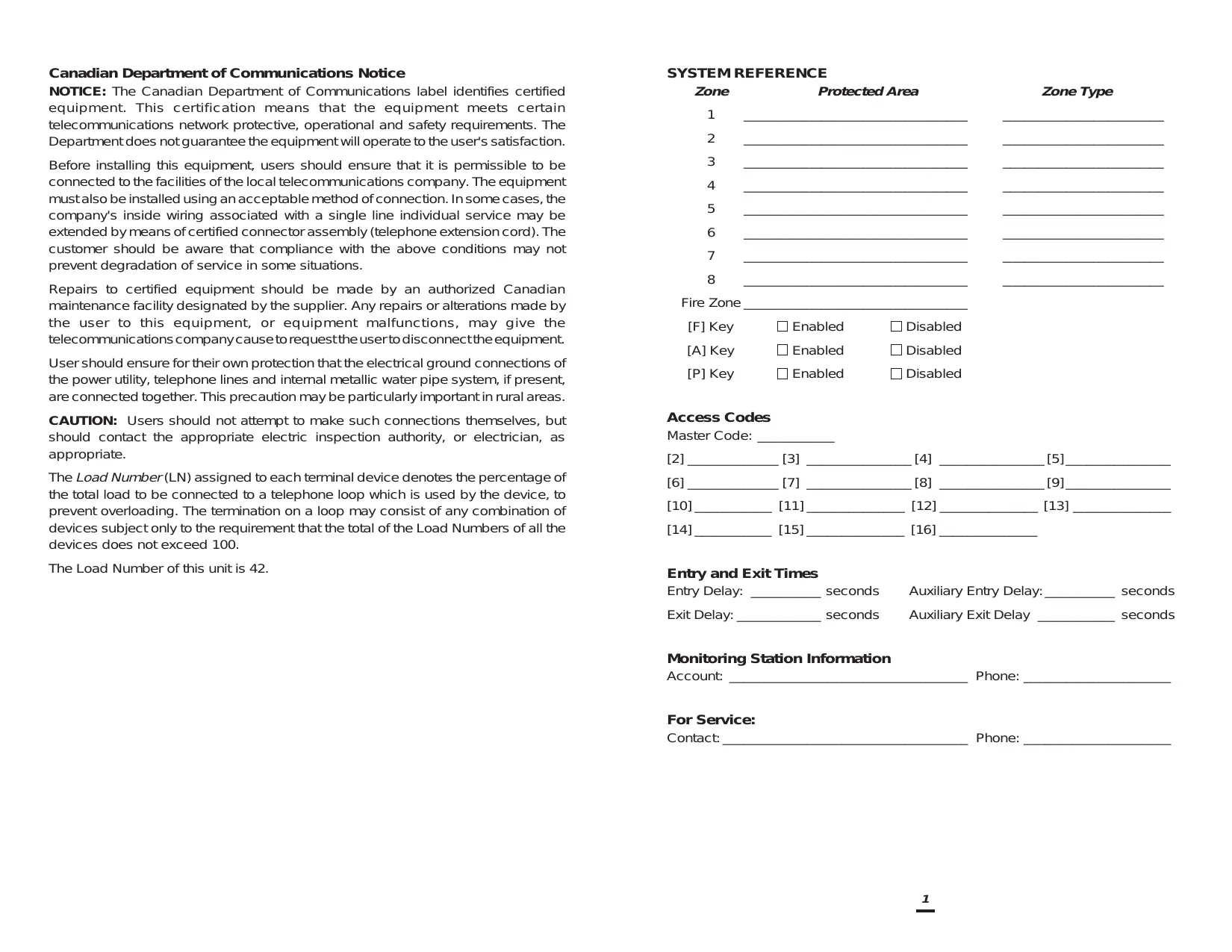
Canadian Department of Communications Notice
NOTICE: The Canadian Department of Communications label identifies certified equipment. This certification means that the equipment meets certain telecommunications network protective, operational and safety requirements. The Department does not guarantee the equipment will operate to the user's satisfaction.
Before installing this equipment, users should ensure that it is permissible to be connected to the facilities of the local telecommunications company. The equipment must also be installed using an acceptable method of connection. In some cases, the company's inside wiring associated with a single line individual service may be extended by means of certified connector assembly (telephone extension cord). The customer should be aware that compliance with the above conditions may not prevent degradation of service in some situations.
Repairs to certified equipment should be made by an authorized Canadian maintenance facility designated by the supplier. Any repairs or alterations made by the user to this equipment, or equipment malfunctions, may give the telecommunications company cause to request the user to disconnect the equipment.
User should ensure for their own protection that the electrical ground connections of the power utility, telephone lines and internal metallic water pipe system, if present, are connected together. This precaution may be particularly important in rural areas.
CAUTION: Users should not attempt to make such connections themselves, but should contact the appropriate electric inspection authority, or electrician, as appropriate.
The Load Number (LN) assigned to each terminal device denotes the percentage of the total load to be connected to a telephone loop which is used by the device, to prevent overloading. The termination on a loop may consist of any combination of devices subject only to the requirement that the total of the Load Numbers of all the devices does not exceed 100.
The Load Number of this unit is 42.
SYSTEM REFERENCE
| Zone | Protected Area | Zone Type |
| 1 | ||
| 2 | ||
| 3 | ||
| 4 | ||
| 5 | ||
| 6 | ||
| 7 | ||
| 8 |
Fire Zone
[F]Key □Enabled □Disabled
[A] Key □ Enabled □ Disabled
[P]Key □Enabled □Disabled
Access Codes
Master Code:
[2] [3] [4] [5]
[6] [7] [8] [9]
[10] [11] [12] [13]
[14] [15] [16]
Entry and Exit Times
Entry Delay: _ seconds Auxiliary Entry Delay: _ seconds
Exit Delay: _ seconds Auxiliary Exit Delay _ seconds
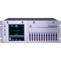
Monitoring Station Information
Account: Phone:
For Service:
Contact: Phone:
A WORD ABOUT YOUR SYSTEM
The PC2550 Security System has been designed to give you the greatest possible flexibility and convenience. Read this manual carefully and become familiar with the operation of your Security System. Your installer will tell you which commands listed in this manual apply to your system. Fill out the SYSTEM REFERENCE sheet in this manual and store it in a safe place for future reference. The label provided for the inside of the keypad door can be used to record which sensors are on each zone.
IMPORTANT NOTE
Remember that no security system can prevent emergencies. It is only intended to alert you in case of an emergency and should not take the place of prudent security practices or life and property insurance.
Notes for UL Installations
The PC2550 is suitable for the following UL installations:
Household Fire and Grade A Burglary
Grade A Local
- Grade B Central Station
- Grade A Police Station Connect with Basic Line Security
- Grade C Central Station
- Grade A Police Connection with Basic Line Security
It is important to test your system every week. To do this, first inform the monitoring station that you are testing your system. Then, with the system disarmed, activate all detection sensors one at a time and observe the zone light come on at the keypad as each sensor is activated. Perform a bell test by entering [][6][Master Code][8] with the system disarmed. The PC2550 can be programmed at the time of installation to automatically perform a test transmission to the monitoring station on a regular basis. If the system has not been programmed for this automatic test, call the monitoring station for instructions on how to perform a test transmission. Don't forget to inform the monitoring station when you have finished your test.
Check to see if the "Trouble" light is on when arming the system. See the Trouble Display section in this manual for a description of the different trouble conditions. Contact your installer for assistance if the trouble condition cannot be located and corrected.
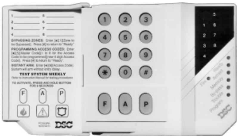
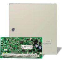
Your Security System is made up of a control panel, one or more keypads, and various detectors and sensors. The control panel will be mounted out of the way in a utility room or basement. The metal cabinet contains the system electronics, fuses and stand-by battery. There is normally no reason for anyone but the installer to have access to the control panel. The keypad(s) have an audible indicator, display lights and command entry keys. The keypad is used to send commands to the system and to display the current system status. Keypads are mounted in convenient areas close to the exit-entry doors. The security system has up to eight zones or areas of protection. Each zone used will have connected to it various sensors, such as door or window contacts, motion detectors, glassbreak detectors and vibration or shock sensors. When a sensor is in alarm, a keypad light will be on to indicate which zone is in alarm.
MASTER CODE
The 4 digit Master Code is used for arming and disarming the system, for programming additional access codes, and for changing other features. The Master Code will be supplied to you by your installer. All keypad entries are made by pressing one key at a time and may be changed by you at any time if the installer selects an option. For additional access codes, see Programming Additional Access Codes.
ARMING
Close all protected doors and windows and stop movement in areas covered by motion detectors. If the "Bypass" light is ON, be sure zones are being intentionally bypassed before arming the system (see Zone Bypassing).
Check to see that the "Ready" light is ON (all zones are closed). The system cannot be armed unless the "Ready" light is ON. Enter a [4 digit access code]. As each digit is entered, the keypad sounder will beep. Once the correct access code is entered, the "Armed" light will come ON and the keypad sounder will beep quickly. If the access code was entered incorrectly or the "Ready" light was not ON, the keypad sounder will beep steadily for 2 seconds.
When the correct code is entered and the system is armed, exit through the door indicated by your installer as the exit-entry door. The exit time may be changed by your installer (please refer to the Quick-Arm feature).
Arming and Commercial Installations
When an Access Code is entered to arm the system, the bell or siren will sound a short tone to indicate that the system is being armed. If your security system is programmed to report to a monitoring station, the keypad will also sound a tone to indicate that the monitoring station has been advised of the arming of the system.
If the system is being armed and the bell or siren fails to sound, or if the keypad does not sound a tone to acknowledge that the monitoring station has been advised of the arming, arrange for service for the system.
AUTO-BYPASS OPTION - HOME-AWAY ARMING
This feature, if selected by your installer, will allow you to arm your system with any valid access code and the system will automatically bypass the interior zones if those interior zones have been designated as home-away zones by the installer. When activated, the "Bypass" light will come ON. If you exit within the allowed exit time, the system will automatically reactivate the interior zones. This feature is designed to save the user from having to manually bypass interior zones each time they wish to arm the system and remain at home.
In residential applications where the system has been armed and the interior zones are automatically bypassed, the interior zones can be reactivated from a keypad outside the interior zones protection area (e.g. a bedroom). To reactivate the interior zones, press [] then [1] and the "Bypass" light will go out.
ENTRY DELAY OFF ARMING
If you wish to arm your system and eliminate the entry delay, enter [][9] before your access code. The "Armed" light will flash as a reminder that the system is armed and has no entry delay. An entry through any zone programmed as a delay zone will create an instant alarm.
e.g. To arm without entry delay.....Press [ 串 ][9][Access Code]
DISARMING
Enter the premises only through the door indicated by your installer as the entry/exit door. The keypad sounder will be ON. Go to the keypad and enter the [4 digit access code]. If an error is made entering the code, press the [#] key and enter the code again. The "Armed" light will go out and the keypad sounder will stop. A correct access code must be entered before the allowed entry time expires. The entry delay time may be changed by the installer.
If an alarm occurred while the panel was armed, the "Memory" light and the light for the zone which caused the alarm will start to flash and will continue flashing for 2 minutes. At the end of 2 minutes, the keypad lights will stop flashing and the keypad will return to the normal Ready condition.
If you return home and find an alarm has occurred while you were away, it is possible that an intruder may still be on the premises. Go to a neighbour's and if your system is monitored, call the monitoring station. They will advise what action has been taken as a result of the alarm and whether the premises are safe to enter. If your system is not monitored, call the local police to investigate.
ALARM MEMORY DISPLAY
If the "Memory" light is on, an alarm has occurred since the last time the panel was armed. The alarm memory will automatically be displayed when the system is disarmed (see Disarming).
Press the [水 ] then [3] keys to display which zone caused the alarm.
The alarm memory will be cleared when the panel is re-armed.
Press the [#] key to return to Ready.
ZONE BYPASSING
Bypassed zones do not cause an alarm. Use zone bypassing when access is needed to part of the protected area. Also, damaged wiring or contacts on a zone may be temporarily bypassed until repairs can be made so that the panel can be armed.
To bypass zones, enter [][1][Access Code] and the zone numbers to be bypassed. i.e. [1] for zone 1, [8] for zone 8. If the [0] key is pressed instead of a zone number, all zone bypasses will be removed. If the [9] key is pressed, the last group of zones which was bypassed will be recalled. Press [#] to return to Ready.
For security reasons, your installer may prevent the bypass command from operating on certain zones.
The "Bypass" light is ON as long as at least ONE zone is bypassed. Do not unintentionally bypass zones when arming. Zone bypasses are automatically cancelled each time the panel is disarmed and must be re-applied before the next arming.
TROUBLE DISPLAY
The PC2550 continuously monitors a number of possible trouble conditions. If one of these conditions occurs, the keypad sounder will beep quickly twice every 10 seconds and the keypad "Trouble" indicator will light. Pressing any key on the keypad will silence the beeper but the "Trouble" light will remain on until the trouble condition is cleared. If you cannot determine the cause of the trouble condition, call your installer for assistance. Press the [×] then [2] keys to display the type of trouble. The zone lights indicate the type of trouble condition.
ZONE LIGHT
TROUBLE
1 Defective Stand-by Battery
2 .AC Power Failure (see Note below)
3 .........Day Circuit Trouble
4 Telephone Line Problem
5 . . . . . . . . . . . . . . . . . . . . . . . . . . . . . . . . . . . . . . . . . . . . . . . . . . . . . . . . . . . . . . . . . . . . . . . . . . . . . . . . . . . . . . . . . . . . . . . . .
1 Unsuccessful Communication Attempt with Monitoring
Station
6 Bell Circuit Failure
7 ... ... ... Smoke Detector Circuit Trouble
8 Loss of Time on System Clock
Press the [#] key to return to Ready.
Note: The keypad buzzer will not sound for AC failure until there is also a low battery condition. The "Trouble" light will come ON as soon as AC fails and will remain on until AC restores.
SMOKE DETECTOR AND FIRE ALARM RESET
If the Fire Alarm sounds at night, do not investigate the alarm: follow your evacuation plan immediately. Go to a neighbor and call the fire department.
When a Fire Alarm is generated, the bell or siren will sound with a pulsing tone. Transmission of the fire alarm to your monitoring station is delayed for 30 seconds to allow you to cancel possible false alarms. To silence the alarm, press the [#] Key. When the [#] Key is pressed, the system will delay transmission of the fire alarm for an additional 90 seconds. The 90-second delay is intended to allow you to reset the smoke detectors after a false alarm.
If the smoke detector is reset and remains reset after the 90-second delay, a fire alarm will not be transmitted to the monitoring station.
If the smoke detector is reset but goes into alarm again after the 90-second delay, the fire alarm will sound again and the process described above will repeat. A fire alarm will be transmitted to your monitoring station after 30 seconds if it is not silenced by pressing the [#] Key.
Smoke detectors installed on your system may be reset after a false alarm using the [][4] command. To reset smoke detectors to normal, first clear all products of combustion from the detectors. Press [] then hold down the [4] key for several seconds. If the detectors are clear of smoke, they will return to normal. If the detectors still have smoke in them, the alarm will sound again. If the alarm sounds again, first ensure that there is no threat of fire; you may then silence the alarm and reset the smoke detectors.
An immediate fire alarm signal and transmission may be generated by holding down the [F] key for 2 seconds.
IMPORTANT
Test system weekly, have system trouble conditions corrected by installer.
PRESS [F] for 2 seconds to activate FIRE transmission.
PRESS [A] for 2 seconds to activate an AUXILIARY transmission.
PRESS [P] for 2 seconds to activate PANIC transmission.
THESE BUTTONS WILL NOT FUNCTION UNLESS PROGRAMMED BY INSTALLER. COLORED LABELS ON KEYPAD DOOR INDICATE WHICH KEYS ARE ACTIVE.
Press[#].....
- when an error is made in entering code, then enter code again.
to return to ready state after using [ ] commands.
Zone Lights, when ON in the normal operating mode, indicate an open zone. eg. open door, window, etc. Refer to zone chart on keypad door for zone information.
Fire light is ON when a detector on the fire loop is in alarm. Press any key within 30 seconds of first alarm to get 2 minutes to reset smoke detectors.
Ready light ON: system ready for arming.
Ready light OFF: open zone; must be closed or bypassed before arming.
Ready, Armed and Program lights flashing indicates user code 9-16 programming.
Armed light will come ON indicating system armed. Ensure "Ready" light is ON, enter [4 digit] access code to arm panel.
Armed, Ready and Program lights flashing indicates user code 9-16 programming.
Memory light ON means an alarm has occurred. To display zone that caused alarm, press [+] then [3]. Zone light will come on indicating which zone caused the alarm.
Bypass light comes ON when you bypass a zone. To bypass a zone, press [] , [1], [Access Code] and then the zone(s) you wish to Bypass. Enter 1 for zone 1....8 for zone 8. Press [#] to return to ready.
Trouble light ON means there is a fault on the system. Press any key to silence keyboard beeping. Press [+] then [2] to display type of trouble.
Zone Light Trouble
1.............. Battery
2 A.C. Power
3 Day loop
4 Telephone line
5 Communicator
6 Bell circuit
7 Smoke detector circuit
8 .........Clock needs resetting
Program light flashes when programming user codes 1 to 8. Press [][5] , then enter [Master Code]. Select a code by pressing a key from 1 to 8 and enter the [4 digit] code. Press [9] to enter codes 9 to 16. "Ready", "Armed" and "Program" lights will flash. Press [#] to return to ready mode.
PROGRAMMING ADDITIONAL ACCESS CODES
Up to 15 access codes in addition to the Master Code can be entered from the keypad.
Enter [][5][Master Code] . The "Program" light will flash and the zone lights will show which of codes 1 to 8 have already been programmed. To enter a new code or change an existing code, first press the code number (1 to 8) and then enter your [4 digit] code. To erase a code, press [] instead of a [4 digit] code. Note that the [] and [#] keys cannot be used in a code.
For codes 9 to 16, after entering [][5][Master Code] , press [9]. The "Ready", "Armed" and "Program" lights will flash and the zone lights 1 to 8 will indicate which of codes 9 to 16 have been entered. As above, to change or enter a code, select the code by pressing 1 to 8 and then enter your [4 digit] code. Entering [***] erases a code. Pressing [9] again will change back to codes 1 to 8.
Pressing [#] returns you to ready mode. Access Code 16 ([*][5][Master Code][9][8][4 digits]) can be set up by your installer to be used by a maid or other service personnel one time only. Each time you enter this code, it can be used to disarm your system but is erased when used to arm the system, ensuring just one-time access.
QUICK-ARM FEATURE
When the Quick-Arm feature is enabled, the panel may be armed simply by entering [][0] instead of a 4 digit code. The [][0] command will not disarm the panel.
Enter [][6][Master Code][4] to turn ON and OFF the Quick-Arm feature. When the command is entered, the keypad will beep 3 times if the feature is being enabled and will sound one long beep if the feature is being disabled.
Press [#] to return to Ready.
QUICK EXIT OPTION
This feature, if selected by your installer, allows one exit with the system armed without affecting its current armed status.
Pressing [][0] gives you 2 minutes to exit if you have already armed the system. This is useful if you want to exit while preserving the protection for someone left on the premises. Once you have exited, the system will be armed as before. If the zone is open after 2 minutes or there has been more than one exit, the prealert will sound.
DOOR CHIME FEATURE
The door chime feature is used, while the panel is disarmed, to provide a tone from the keypad each time a door or window is opened or closed. The doors and windows which will provide this indication are programmed by your installer.
Enter [][6][Master Code][6] to turn the door chime feature ON and OFF. When the command is entered, the keypad will beep 3 times if the feature is being enabled and will sound one long beep if the feature is being disabled.
ALARM TEST
Enter [*][6][Master Code][8] for a 2 second test of the keypad lights, keypad sounder and alarm bells.
ENTERING ACCESS CODES SUMMARY:
[*][5][Master Code]...
[1 to 8] [4 digits] Programs first group of 8 codes
[9] [1 to 8] [4 digits] Programs second group of 8 codes
[9] Returns to first group of 8 codes
[#] exits to the Ready mode
USER FUNCTIONS COMMAND SUMMARY:
[*][6][Master Code]...
[4] Quick-Arm Enable/Disable
[6] Door Chime Enable/Disable
[8] Bell Test Function
KEYPAD ZONES
There are three zones which can be activated from the keypad. These zones may or may not be active on your keypads depending on how your installer has programmed them.
[F] Key: Keypad FIRE zone. Pressing this key for 2 seconds will activate the keypad fire zone and the bell/siren output will pulse ON and OFF. This zone is annihilated by the "Fire" light on the keypad.
[A] Key: Keypad AUXILIARY zone. Pressing this key for 2 seconds will produce a series of beeps on the keypad along with the transmission. To confirm transmission, the keypad sounder will beep 6 times.
[P] Key: Keypad PANIC zone. Depending on how your installer programs the panel, pressing this key for 2 seconds may produce a completely silent alarm or an audible alarm along with the transmission. If programmed as audible, the alarm bell will ring.
MAINTENANCE
With normal use, the system requires minimum maintenance. The following should be observed:
- Do not wash the keypad with a wet cloth. Light dusting with a barely damp cloth should remove normal accumulations of dust.
- The battery/bell test is designed to determine battery condition, however it is recommended that the stand-by battery be replaced every three years.
- For other system devices such as smoke detectors, passive infrared, ultrasonic or microwave motion detectors or glassbreak detectors, consult the respective manufacturer's literature for testing and maintenance.
TESTING
IT IS RECOMMENDED THAT THE SYSTEM BE TESTED ON A WEEKLY BASIS
Note: Perform such activities in the off-peak hours, such as early morning or late evening.
- Inform the monitoring station that you are testing your system.
- Disarm the system ("Ready" light should be ON).
- Perform a battery/bell test by pressing [][6][Master Code][8] . The alarm will sound for about 2 seconds. If a trouble occurs after the test, press [][2] to view the trouble condition.
- Activate each sensor in turn. For example, open a door or window. Observe the zone light come ON as each sensor is activated. The zone light will go OFF as each sensor is restored to normal (door or window is closed).
- Press the [F] key. The signal will sound in a pulsed mode. Arm then disarm the panel to silence the signal. Repeat this test by pressing the [A] key and the [P] key in turn. Remember, the [A] key does not ring the bell and the [P] key may not be programmed for an audible signal.
- If the fire zone is used, activation will cause the signal to sound in a pulsed mode.
CAUTION: Do not use open flame or burning materials to test a smoke detector. Contact your installer for information on safe methods to activate a smoke detector.
- Should your system fail to operate properly, call your installer for service.
- When testing is complete, call and advise the monitoring station.
FIRE SAFETY IN THE HOME
Most fires occur in the home and to minimize this danger it is recommended that a household fire safety audit be conducted and a family escape plan be developed.
HOUSEHOLD FIRE SAFETY AUDIT
- Are all electrical appliances and outlets in a safe condition? Check for frayed cords, over-loaded lighting circuits, etc. If you are uncertain about the condition of your electrical appliances or household service, have a professional evaluation.
- Are all flammable liquids stored safely in closed containers in a well ventilated cool area? Cleaning with flammable liquids should be avoided.
- Are fire hazardous materials (matches) well out of reach of children?
- Are furnaces and wood burning appliances properly installed, clean and in good working order? Have a professional evaluation.
FAMILY ESCAPE PLANNING
There is often very little time between the detection of a fire and the time it becomes deadly. It is thus very important that a family escape plan be developed and rehearsed.
- Every family member should participate in developing the escape plan.
- Study the possible escape routes from each location within the house and since many fires occur at night, special attention should be given to the escape routes from sleeping quarters.
-
It is essential that escape from a bedroom be possible without opening the interior door. Consider the following when making your escape plans:
-
Make sure that doors and windows that open to the outside are easily opened. Ensure that they are not painted shut, and that their locking mechanisms operate smoothly.
- If opening the exit or using the exit is too difficult for children, the elderly or handicapped, plans for rescue should be developed. This includes making sure that those who are to perform the rescue can promptly hear the fire warning signal.
- If the exit is above the ground level, an approved fire ladder or rope should be provided as well as training in its use.
- Exits on the ground level should be kept clear. Be sure to remove snow from exterior patio doors in winter; outdoor furniture or equipment should not block exits.
- The family should have a predetermined assembly point where everyone can be accounted for; for example, across the street or at a neighbour's house.
- Once everyone is out of the house, call the Fire Department.
- A good plan emphasizes quick escape. Do not investigate first or attempt to fight the fire, and do not attempt to rescue belongings or pets as this takes up valuable time. Once outside, do not re-enter the house. Wait for the fire department.
- Write the plan down and rehearse frequently, so that should an emergency arise, everyone will know what they are to do. Revise the plan as conditions change; for example, when there are more or fewer family members in the home, or if there are changes to the house.
- Make sure your fire warning system is operational by conducting weekly tests as noted elsewhere in this manual. If you are unsure about system operation, contact your installing dealer.
- It is recommended that you contact your local fire department and request further information on home fire safety and escape planning. If available, have your local fire prevention officer conduct an in-house fire safety inspection.
LIMITED WARRANTY
Digital Security Controls Ltd. warrants that for a period of twelve months from the date of purchase, the product shall be free from defects in materials and workmanship under normal use and that in fulfilment of any breech of such warranty, Digital Security Controls Ltd. shall, at its option, repair or replace the defective equipment upon return of the equipment to its repair depot. This warranty applies only to defects in parts and workmanship and not to damage incurred in shipping or handling, or damage due to causes beyond the control of Digital Security Controls Ltd., such as lightning, excessive voltage, mechanical shock, water damage, or damage arising out of abuse, alteration or improper application of the equipment.
The foregoing warranty shall apply only to the original buyer, and is and shall be in lieu of any and all other warranties, whether expressed or implied and of all other obligations or liabilities on the part of Digital Security Controls Ltd. Digital Security Controls Ltd. neither assumes, nor authorizes any other person purporting to act on its behalf to modify or to change this warranty, nor to assume for it any other warranty or liability concerning this product.
WARNING:
Digital Security Controls Ltd. recommends that the entire system be completely tested on a regular basis. However, despite frequent testing, and due to but not limited to, criminal tampering or electrical disruption, it is possible for this product to fail to perform as expected.
- Canadian Department of Communications Notice
- SYSTEM REFERENCE
- Access Codes
- Entry and Exit Times
- Monitoring Station Information
- For Service:
- A WORD ABOUT YOUR SYSTEM
- IMPORTANT NOTE
- Notes for UL Installations
- MASTER CODE
- ARMING
- Arming and Commercial Installations
- AUTO-BYPASS OPTION - HOME-AWAY ARMING
- ENTRY DELAY OFF ARMING
- DISARMING
- ALARM MEMORY DISPLAY
- ZONE BYPASSING
- TROUBLE DISPLAY
- ZONE LIGHT
- TROUBLE
- SMOKE DETECTOR AND FIRE ALARM RESET
- IMPORTANT
- Press[#].....
- Zone Light Trouble
- PROGRAMMING ADDITIONAL ACCESS CODES
- QUICK-ARM FEATURE
- QUICK EXIT OPTION
- DOOR CHIME FEATURE
- ALARM TEST
- ENTERING ACCESS CODES SUMMARY:
- USER FUNCTIONS COMMAND SUMMARY:
- KEYPAD ZONES
- MAINTENANCE
- TESTING
- IT IS RECOMMENDED THAT THE SYSTEM BE TESTED ON A WEEKLY BASIS
- FIRE SAFETY IN THE HOME
- HOUSEHOLD FIRE SAFETY AUDIT
- FAMILY ESCAPE PLANNING
- LIMITED WARRANTY
- WARNING:
Brand : DSC
Model : PC2550
Category : Security alarm