USER MANUAL EC 250 GAS GAS
This manual was created by GAS GAS Motos, S.A. for the use of official GAS GAS services. It is principally directed at operators with a basic knowledge of the principles of mechanics and repair techniques. It contains precise instructions for making all the repairs, in addition to the necessary technical data to carry out the maintenance of the motorbikes.
There is also considerable information about the special GAS GAS tools and equipment that will be of great help in optimising repair processes.
In successive editions, we will keep you informed of all the updates and evolution of the motorbikes in this family.
Particularly important information in the manual is preceded by one of the following symbols.

Note: indicates points of particular interest for more efficient and convenient operation.

Warning: indicates special instructions or procedures which should be followed to the letter to avoid damaging the equipment.

Danger: indicates special instructions or procedures which must be followed to the letter to avoid physical injury to the operators.
GAS GAS Motos, S.A
CONTENTS
Sect. P.
IV GENERAL INFORMATION
VI TABLE OF TECHNICAL DATA
01 01 REMOVING THE ENGINE FROM THE CHASSIS
02 01 FITTING THE ENGINE ON THE CHASSIS
03 01 DISounting ENGINE
04 01 SERVICE AND REPAIR OF THE ENGINE COMPONENTS
05 01 ASSEMBLING THE ENGINE
06 01 ELECTRICAL SCHEMAS
Certain safety and maintenance norms should be remembered when carrying out repairs to the vehicles. Some of the more important norms are listed below:
Safety
- Do not smoke or cause sparks or naked flames in the work area. Petrol is highly inflammable and may be explosive in certain conditions.
- Use cleaning products appropriate to each task, ensuring that they have been approved.
- Always wear protective eye equipment when using electric tools such as drills, sanders or grinders.
- Apply a protective hand cream before commencing dismantling work. This protects the skin from infection and makes subsequent cleaning easier. Ensure that hands are not slippery.
- Remember that prolonged contact of the skin with engine oil can be damaging to health.
- Keep loose clothing away from moving parts.
- Do not wear rings, wristwatches, etc while working on the engine, especially the electrical system.
- Keep the work area tidy, it is easy to trip over elements left on the floor.
- Avoid leaving oils, grease or other fluids on the floor of the work area to avoid slipping on them.
- Use suitable tools for compressing or decompressing springs to prevent these from escaping suddenly.
- Take special care not to inhale dust from parts containing asbestos (for example: clutch discs), this product is extremely dangerous for your health.
- Avoid inhaling fumes from petrol or cleaning fluids, these can be highly toxic. Ensure that the work area is well-ventilated.
Maintenance
- Always use original GAS GAS spare parts and lubricants recommended by the manufacturer. Other spare parts may damage the engine.
- Only use the tools specified for this vehicle.
- Always replace all the gaskets, seals and O-rings during service and assembly.
- After dismounting, clean components with non-inflammable dissolvent.
- Lubricate all work surfaces before assembly, except the conical couplings.
- Oil all the paired parts and bearings when assembling.
- When removing, servicing and assembling parts, only use metric-sized tools. Metric screws, nuts and bolts are not interchangeable with parts with Imperial measurements.
- All the surfaces receiving gaskets, seals and O-rings must be carefully cleaned.
- Carefully examine all the circlips before assembly and replace any which are damaged. Always replace the piston pin circlip after each use.
- After assembly check all the components are correctly fitted and the mechanisms are working perfectly.
General tightening torques
The following table specifies tightening torques for nuts or bolts with ISO threads.
Tightening torques for components or special units are given in the relevant repair process described in this manual.
To avoid damage, tighten units with various nuts or bolts progressively and in diagonal or alternate pairs, until obtaining the specified torque.
To apply the tightening torques described below, clean, dry threads are necessary. Components should be at room temperature.
| *(A) NUT | *(B) BOLT | GENERAL TIGHTENING TORQUES |
| Nm | Kgf.m | Ft.lb |
| 10 mm | 6 mm | 6 | 0,6 | 4,3 |
| 12 mm | 8 mm | 15 | 1,5 | 11 |
| 14 mm | 10 mm | 30 | 3,0 | 22 |
| 17 mm | 12 mm | 55 | 5,5 | 40 |
| 19 mm | 14 mm | 85 | 8,5 | 61 |
| 22 mm | 26 mm | 130 | 13,0 | 94 |
^ A: Distance between the nut faces.
B: External diameter of screw thread.
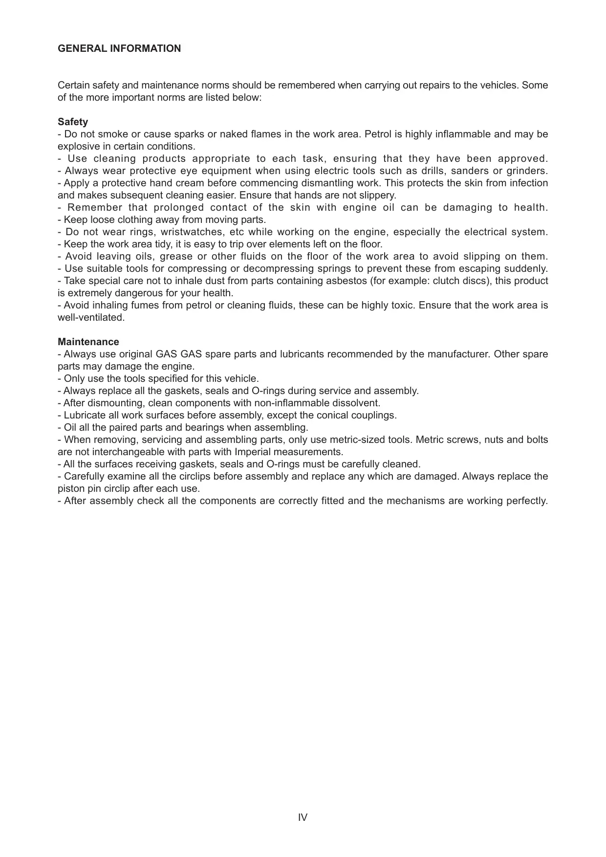
Engine serial number
The engine serial number is stamped on the lower part of the left crankcase.
Remember to quote the engine serial number each time you place an order for an original GAS GAS spare part for said engine.
| TABLE OF TECHNICAL DATA |
| Engine |
| Definition | Mono-cylindrical 2-stroke engine, liquid-cooled, intake to crankcase |
| Displacement in cubic centimetres | 200 Engine: 199.4cc |
| 250 Engine: 249.3cc |
| 300 Engine: 294.7cc |
| Fuel | RON / SUPER-LEAD-FREE 95-98 octane.Mixed with SYNTHETIC 2T oil |
| Mixture ratio | 100% synthetic oil: petrol 50: oil 1 (2%) |
| Petrol / oil | semi-synthetic oil: petrol 40: oil 1 (2.5 %) |
| Bore and stroke | 200 Engine: 62.5 x 65 mm |
| 250 Engine: 66.4 x 72 mm |
| 300 Engine: 72 x 72 mm |
| Spark plug | NGK BR8EG |
| Electrode separation | 0.7 - 0.8 mm |
| Ignition timing | 1 mm BTDC |
| Piston rings: quantity | 2 rings |
| Starter system | Kick-start pedal |
| System | Liquid-cooled, with impulse pump |
| Circuit capacity | 1.1 litres |
| Mix ratio | Distilled water: 50%Antifreeze: 50 % |
| System | Carburetion |
| Carburettor | KEIHIN PWK 38 |
| Fuel tank | 9 litres |
| Fuel supply | Gravity |
| Air filter | Dry air filter |
| Ignition system | CDI system |
| Voltage / Power | 12 V / 110 W |
| Transmission | 6-speed cascade |
| Clutch | Oil bath, multi-disk hydraulic action |
| Secondary transmission | By chain |
| Gear ratio | |
| 1st gear | 2.071 (29/14) |
| 2nd gear | 1.625 (26/16) |
| 3rd gear | 1.333 (24/18) |
| 4th gear | 1.100 (22/20) |
| 5th gear | 0.913 (21/23) |
| 6th gear | 0.791 (19/24) |
| Primary reduction ratio | 200 cc: 3.22 (58/18); 250 - 300 cc: 2.85 (57/20) |
| Final reduction ratio | 3.615 (47/13) |
| Overall drive ratio (6th gear) | 200 cc: 9.21; 250 - 300 cc: 8.149 |
| Oil type | 10W30 API SF or SG |
| Oil capacity | 900 cc |
| Engine | 200 cc / 250 cc / 300 cc | G |
| EC ENDUCROSS WORKSHOP MANUAL |
| Ed: 07/05 | REMOVING THE ENGINE FROM THE CHASSIS | 01-01 |

Note:
The cylinder head, the cylinder, the clutch and the ignition, can be removed without dismounting the engine from the chassis.
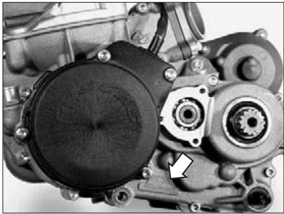
- Thoroughly clean the motorcycle before starting to dismantle the engine.
- Place the motorcycle on a support suitable for work.
- Remove the seat.
- Dismantle the plastic covers on both sides.
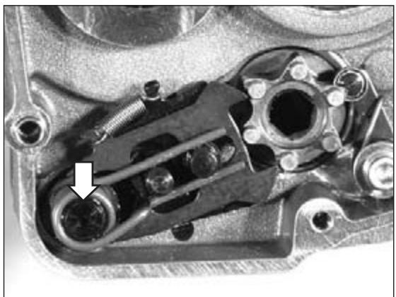
- Remove the fuel tank.
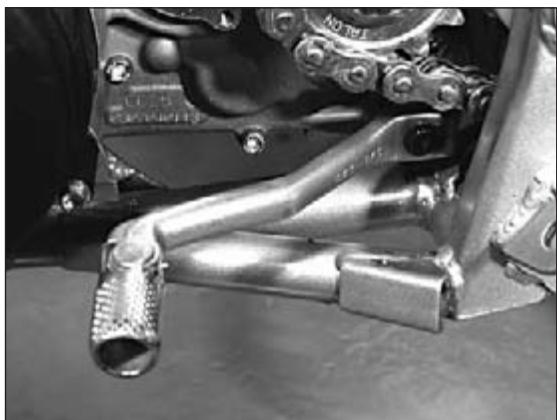
- Remove the lever from the kick-start pedal - arrow-.
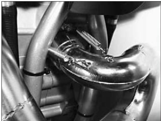
- Release the springs holding the exhaust pipe to the cylinder pipe.
| 01-02 | REMOVING THE ENGINE FROM THE CHASSIS | Ed: 07/05 |

- Remove the whole exhaust system.

Note: The oil must never be poured down the drain or into the environment.

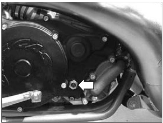
- Remove the drain plug -arrow- and drain the transmission oil.

Danger:
Make sure that the coolant fluid is not hot before opening the coolant circuit.

Note: Place the coolant in a clean container, it may be reused later.
- Remove the radiator cap.
- Unscrew the coolant drain plug in the water pump and allow the fluid to drain into the container.
- Clean any fluid which falls on the engine, chassis or wheels.
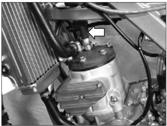
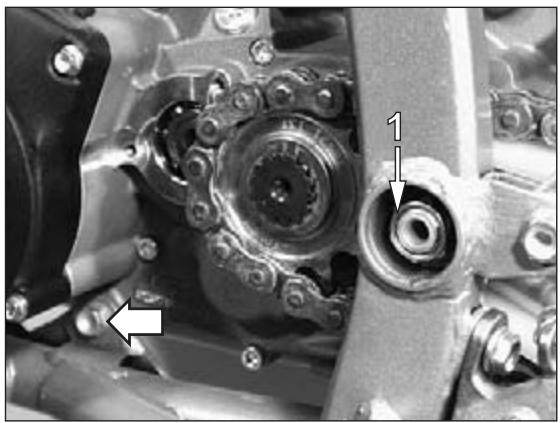
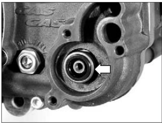
- Disconnect the spark plug connector -1- and disconnect the coolant pipes on both sides of the engine.
- Remove the back brake pedal and the back brake pump guard, setting them to one side.
Ed: 07/05
REMOVING THE ENGINE FROM THE CHASSIS
01-03

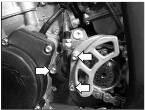
- Undo the screws -arrows-, remove the chain pinion and the hydraulic clutch calliper with the gasket.
- Loosen the chain.
- Extract the clutch rod -arrow- entirely.

Note:
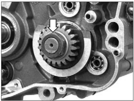
The position of the chain pinion before removing. It should be replaced in the same position to ensure the same direction of wear.
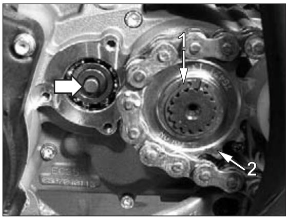
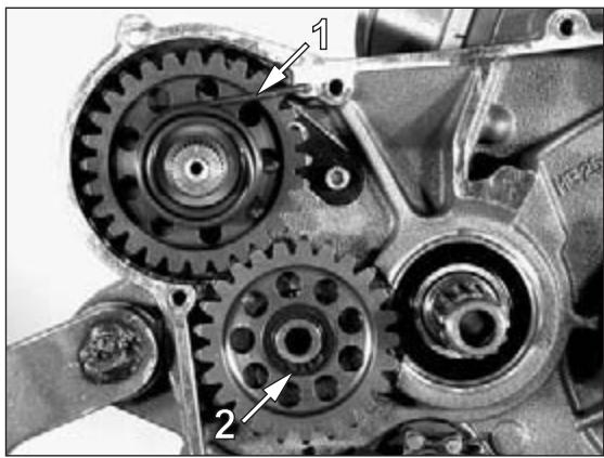
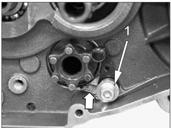
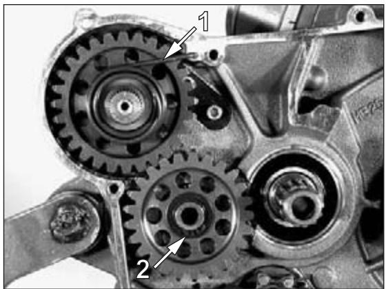
- Remove the circlip -1- of the chain pinion using circlip pliers.
- Remove the chain pinion -2- from the secondary shaft.

- Remove the gear lever.
- Release the magnetic flywheel wiring from its fastening on the chassis; disconnect the connector on the control unit (CDI) and the remaining wiring connectors.

01-04 REMOVING THE ENGINE FROM THE CHASSIS
Ed: 07/05
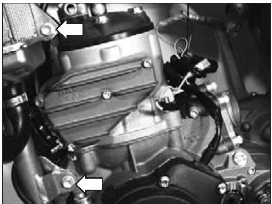
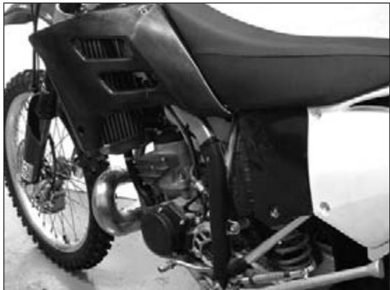
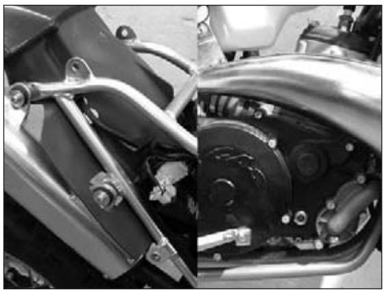
- Remove the screws -arrows- fastening the engine to the chassis.
- Loosen the screw fastening the cylinder head support to the chassis.
- Remove the screw -arrow- fastening the engine to the lower chassis.
- Remove the nut -1-, remove swing arm and move backwards.
- Position the engine ready for removal and then take off.
| Engine | 200 cc / 250 cc / 300 cc | G |
| EC ENDUCROSS WORKSHOP MANUAL |
| Ed: 07/05 | FITTING THE ENGINE ON THE CHASSIS | 02-01 |
- Fit the engine on the chassis and correctly position on the supports.
- Line up swing arm with the engine and chassis, grease swing arm and fit.
- Place engine fastening screws in supports.

Note: The self-locking fastening nuts of the engine must be replaced with new nuts.
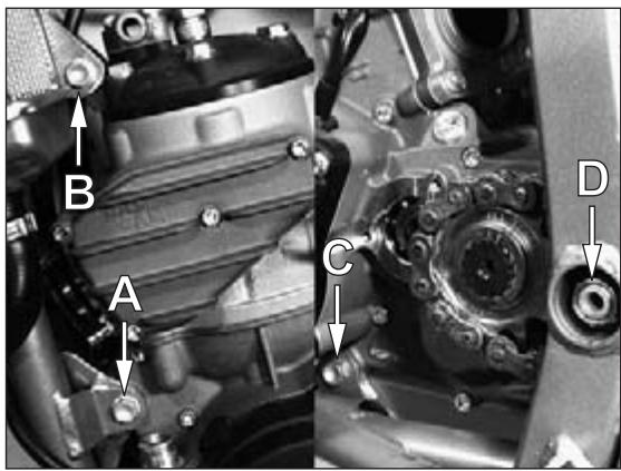
- Tighten all the nuts slightly and then to the specified torque:
| Nuts | Tightening torque |
| A | 38 to 48 Nm |
| B | 24 to 29 Nm |
| C | 38 to 48 Nm |
| D | 66 Nm |
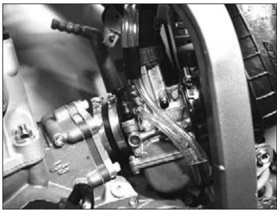
- Assemble the carburettor.
- Place the magnetic flywheel on the chassis and fasten correctly.
- Connect the control unit connector and the remaining wiring connectors.
Tightening torque: 15 Nm

Note:
The chain pinion must be fitted in the same position as when it was removed to ensure the same direction of wear.
02-02 FITTING THE ENGINE ON THE CHASSIS
Ed: 07/05
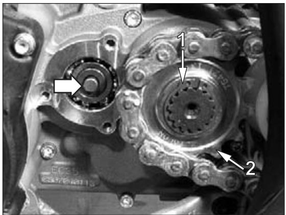
- Place the chain pinion -2- on the secondary shaft and fit the circlip -1-.
- Fit the clutch rod -arrow-.
Tightening torque: 29 Nm

Note:
Check that the coolant pipes are not cut or worn.
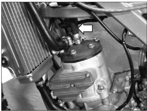
- Connect the spark plug connector -arrow- and connect the coolant pipes on both sides of the engine.

Note:
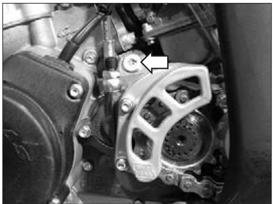
Ensure that the coolant drain plug in the water pump is screwed in tightly and has a new seal.
Tightening torque: 9 Nm
- Disconnect the coolant recirculation pipe.
- Fill the coolant system through the left radiator cap. Mixture of coolant and distilled water: 1:1 (antifreeze 50% , distilled water 50% ).
Capacity 1.1 litres.

Note:
Ensure that the transmission oil drain plug is tightened and has a new gasket.
Tightening torque: 20 Nm
Ed: 07/05
FITTING THE ENGINE ON THE CHASSIS
02-03
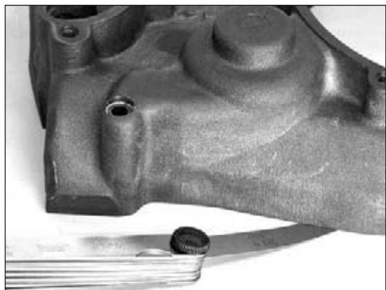
- Remove the oil filler cap -arrow- and fill with new transmission oil.
Viscosity: 10W30
Capacity 900 cc
- Fit the oil filler cap with a new gasket and tighten.
- Pump the starter pedal 3 or 4 times and check the oil level through the indicator -arrow-.
- Apply Nural 29 to the exhaust system unions.
- Fit the complete exhaust system and tighten screws slightly.

- Check the condition of the O-rings of the exhaust; if they are deteriorated, replace them.
- Correctly fit the springs holding the exhaust pipe to the cylinder pipe.
- Tighten the exhaust system screws.
Tightening torque: 6 Nm
02-04 FITTING THE ENGINE ON THE CHASSIS
Ed: 07/05

- Fit the kick-start pedal lever, apply Loctite 243 to the screw -arrow- and then tighten.
- Tightening torque: 20Nm
- Fit the fuel tank and the vent hose.
- Check the condition of the air filter. If it is damaged, replace with a new one. If it is undamaged, clean and refit (see user manual).
- Replace the plastic covers on both sides of the motorcycle.
- Fit the seat.

Note: After the first stage of running in, check the oil and coolant levels, the chain tension and generally inspect the engine.
- Check no coolant is leaking from the radiator hoses.
Prior instructions:

Note:
When dismounting the engine keep all the paired parts together. This includes gears, cylinders, pistons and other parts subject to natural wear in pairs.
Paired components must always be replaced together.
During the disassembly, clean all the parts and place them on trays in the order they are removed. This will accelerate assembly and ensure the correct installation of all the parts. Parts should be kept away from any source of fire.
All gaskets, seals and O-rings should be replaced whenever the engine is dismounted partially or completely.
- Thoroughly clean engine before placing on work bench.
- Place the motor on the bench.
- Remove spark plug from cylinder head.

Dismantling the ignition
- Undo the screws -arrows- of the ignition cover.
03-02 DISounting Engine
Ed: 07/05
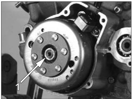
- Block the magnetic flywheel.
- Remove the nut -1-.

Warning:
The magnetic flywheel nut is loosened by turning to the left!
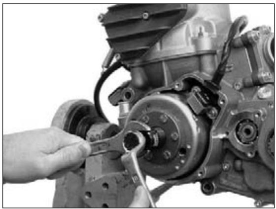
- Insert the extractor ref. ME25634045 on the internal thread of the magnetic flywheel.
- Remove the magnetic flywheel by holding the extractor with a wrench while threading the screw.
- Remove the pin from the crankshaft.
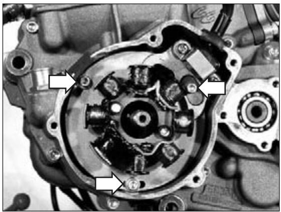
- Undo the screws -arrows- from the ignition stator and remove it with the wiring.
Dismantling the water pump
- Undo the screws -arrows- of the water pump cover.

| Engine | 200 cc / 250 cc / 300 cc | G |
| EC ENDUCROSS WORKSHOP MANUAL |
| Ed: 07/05 | DISCOUNTING ENGINE | 03-03 |

- Block the turbine -1- of the water pump.
- Undo the fastening screw -2- and remove the turbine from the water pump.

- Remove the complete seal -arrow- from the water pump.
Removing cylinder head and cylinder
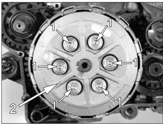
- Undo bolts -1- on the clutch disc cover and remove cover.
- Undo bolts -2- on the clutch cover and remove cover.
- Remove the clutch cover gasket.
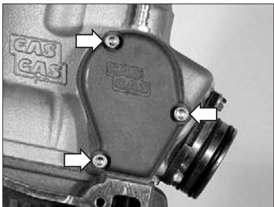
- Undo the screws -arrows- of the exhaust valve right-hand cover.
03-04 DISounting Engine
Ed: 07/05
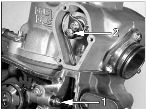
- Remove the fastening nut -1- from the operating lever and the nut -2- from the exhaust valve rod.
- Loosen screws -1- and remove thermostat cover.
- Loosen cylinder head screws -2- in diagonal pairs and remove cover from cylinder.

Note: If the cylinder head does not come off easily hit lightly with a plastic hammer.
- Remove inner and outer O-rings of the cylinder head.

- Undo the screws -arrows- of the exhaust valve left-hand cover.

- Remove the fastening nuts -arrows- from the cylinder to the crankcase, on both sides of the engine.
- Remove the cylinder by lifting upwards.

Note: If the cylinder does not come off easily hit lightly with a plastic hammer.
- Remove the cylinder gasket.
| Engine | 200 cc / 250 cc / 300 cc | G |
| EC ENDUCROSS WORKSHOP MANUAL |
| Ed: 07/05 | DISCOUNTING ENGINE | 03-05 |

Note: There may be more than one gasket.
- Mark the orientation of the piston towards the exhaust port using a permanent marker.
- Place a clean cloth at the base of the cylinder to prevent the circlip from falling in the crankcase.
- Remove a circclip from the pin and take out the pin by pushing from the opposite end.

Note: If necessary, gently tap the pin using a suitable tappet.
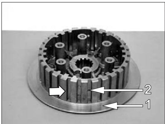
Dismantling the clutch

Note: If the clutch is being removed in order to, for example, replace the discs, it is not necessary to remove the complete clutch cover. To access the clutch discs it is only necessary to remove the clutch disc cover.
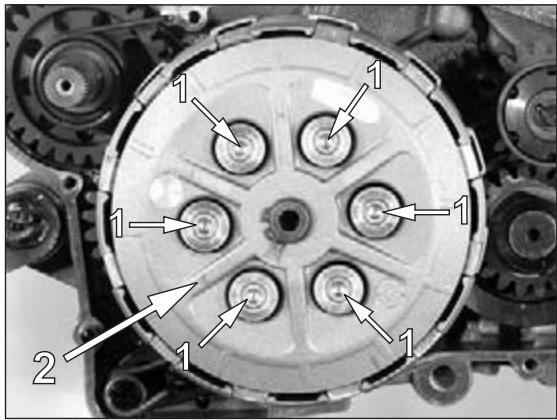
- Remove the screws -1- undoing in diagonal pairs.
- Remove the clutch springs and the rod bushings.
- Remove the clutch press -2-.
- Remove the set of clutch discs from the housing.
03-06 DISounting Engine
Ed: 07/05
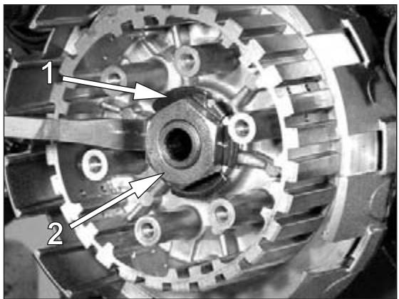
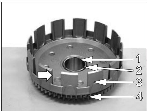
- Open the safety catch -1- of the fastening nut of the clutch hub -2-.
- Loosen the nut by holding the clutch hub.
!
Warning:
The clutch hub nut is loosened by turning to the left!
- Remove the lock washer and take out the clutch hub.
i
Note:
The clutch hub has an assembly position with respect to the primary shaft. Mark the position using a permanent marker on the grease ring.
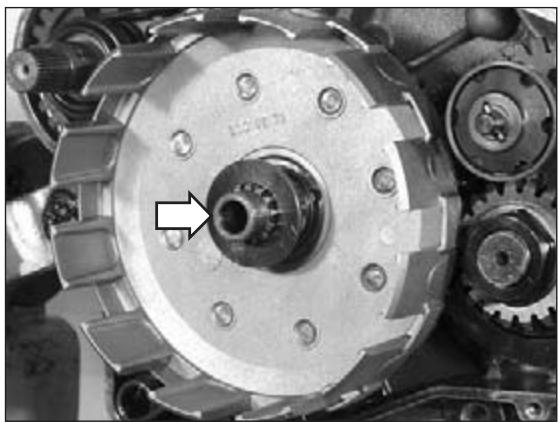
- Remove the clutch housing washer.
- Remove the clutch housing.
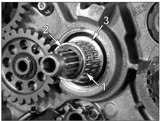
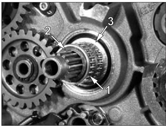
- Remove the clutch housing bearings -1-, the bushing -2- and the washer -3-.
Ed: 07/05
DISounting Engine
03-07

Dismount the centrifugal operating system of the exhaust valve
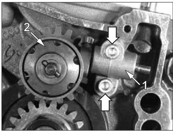
- Take the shaft and pinion off the water pump.
- Undo the screws -arrows- and remove the support -1- from the exhaust valve control shaft.
- Remove the centrifugal mechanism from the exhaust valve -2-.
Dismantling the starter pinion unit
- Dismount the spring -1- using pliers and remove the starter pinion unit.
- Remove the circclip -2-, remove the spacer washer, and take off the inner starter pinion.
Dismantling the gear selector unit
- Remove the complete selector rod -arrow- by pulling outwards.
- Remove the selector rod bushing -arrow-.
03-08 DISCOUNTING ENGINE
Ed: 07/05
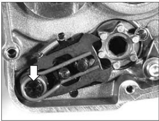
- Loosen the spring -arrow- of the gear lock using pliers.
- Remove the screw -1- and take out the gear locking unit -2-.
Dismantling crankshaft flywheel

Warning:
The locking nut of the crankshaft is loosened to the right!
- Block the crankshaft pinion and loosen the nut -arrow- (the 200 cc engine is fitted with a hexagonal screw).

Note:
The 200 cc engine is not fitted with flywheel.
- Remove the nut, the bevelled washer, the crankshaft pinion, the flywheel and the crankshaft pin.

Dismounting the reed valve
- Undo the screws -arrows- and remove the reed valve.
Ed: 07/05
DISounting Engine
03-09

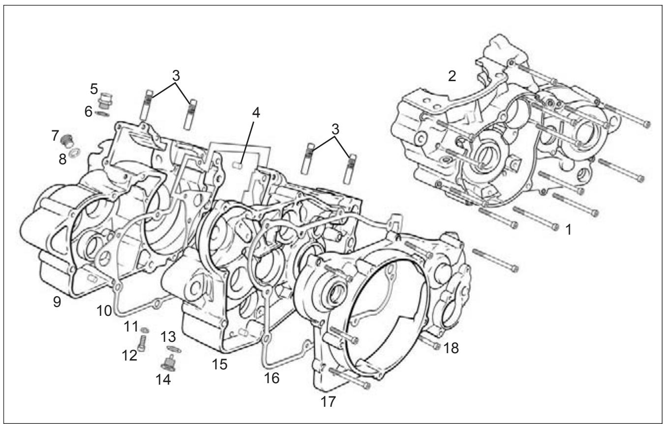
Removing the half crankcases
- Undo the screws -arrows- fastening the half crankcases.
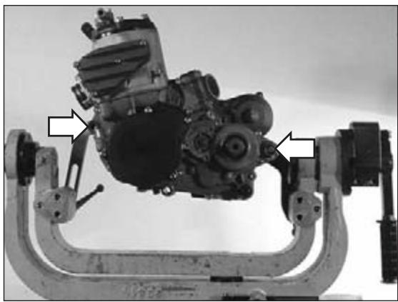
- Turn the bench so that the left-hand half of the crankcase is facing upwards and remove the nut fastening the engine to the bench.
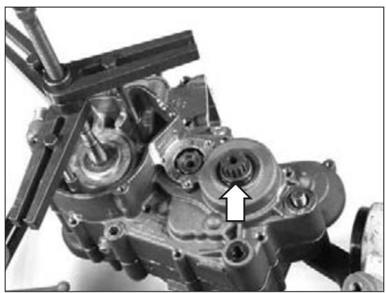
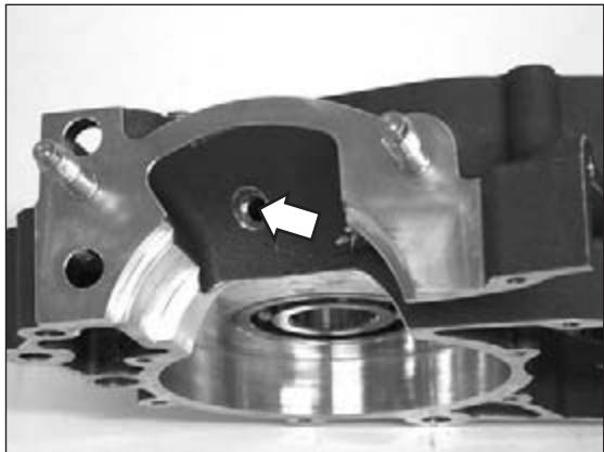
- Install the extractor ref. ME25950000 threading the feet into the openings of the ignition stator as shown in the image.

Note:
The height of the extractor feet is adjustable; they should be parallel to the surface of the half crankcase.
- Activate the extractor until the left-hand half of the crankcase is completely separated from the right-hand half.
- During the extraction, remove the spacer hub from the engine pinion -arrow- which is located on the shaft.

Warning:
Do not use screwdrivers or levers to separate the crankcase halves!
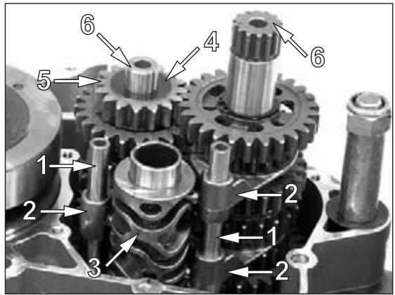
Removing the selector rod and gears from the gearbox
- Remove the fork pivots -1- and remove forks -2-.
- Mark the position of the desmodromic valve -3- with respect to the half crankcase and then remove.
- Remove the adjustment washer -4- and the gear of II speed -5-.
- Remove the gear cams -6- by carefully pulling them upwards.

Note:
The pinions of V and I speed do not come out together with the gear caps.
03-10 DISCOUNTING ENGINE
Ed: 07/05

- Remove the pinions of V and I gear -arrows-, the needle bearing and the adjustment washers.
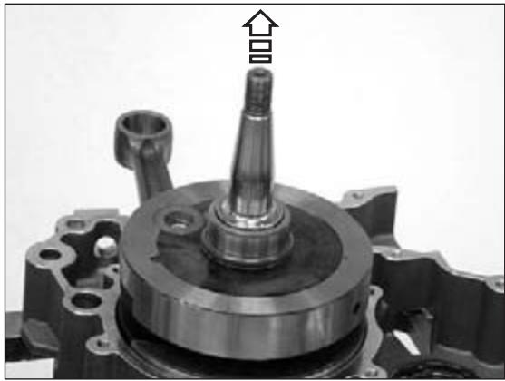
Removing the crankshaft
- Remove the crankshaft unit -arrow- by pulling upwards.

Note:
If the crankshaft does not come off easily alternately tap the two shafts gently with a plastic hammer.
- On the side opposite the dismounted half crankcase, first remove the bushing -arrow- from the crankshaft seal and then the O-ring.

Note:
All gaskets, seals and O-rings should be replaced whenever the engine is dismounted partially or completely.
Crankshaft- Piston - Cylinder
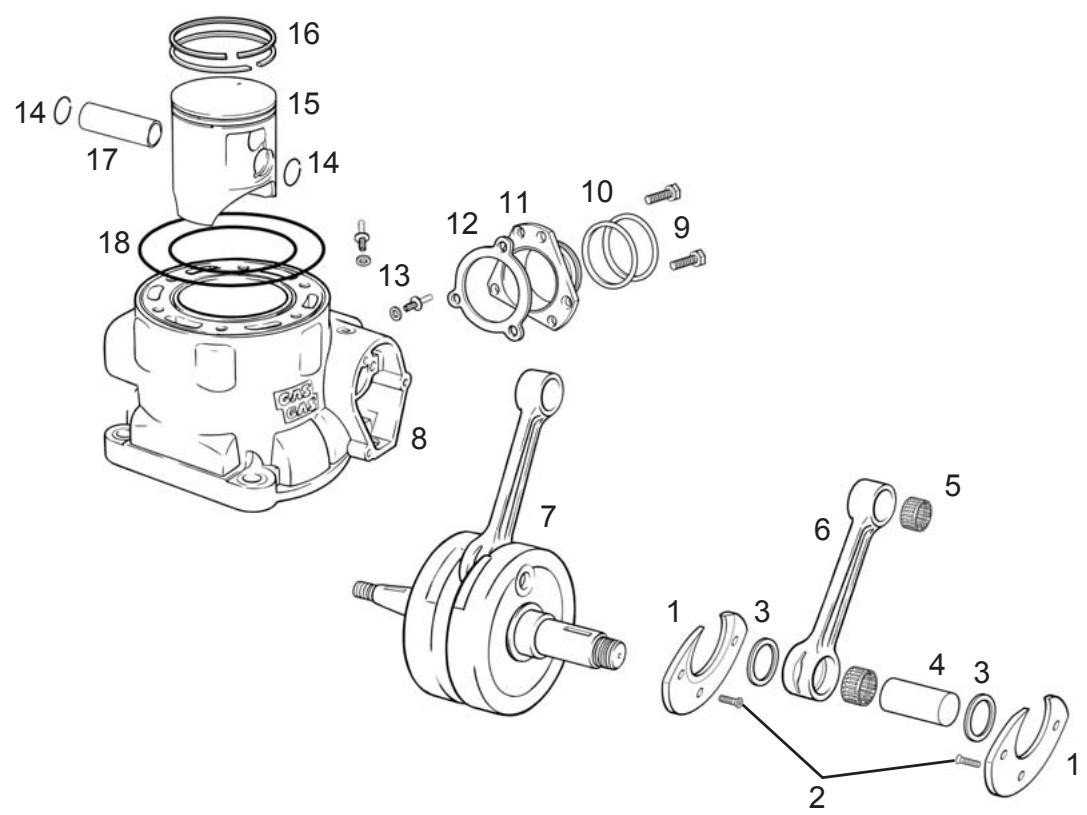
- Nylon counterweight
- Nylon counterweight screws
- Washer
- Connecting rod piston pin
- Connecting rod small end bearing 18x22x22
- Connecting rod
- Crankshaft unit
- Cylinder
- Hexagonal bolt with 6x14 washer
- Viton exhaust duct O-ring 44x3
- Exhaust duct
- Exhaust gasket
- Vent
- Piston pin circlip
- Piston
- Set of rings
- Piston pin
- Cylinder head O-ring gaskets
04-02 SERVICE AND REPAIR OF THE ENGINE COMPONENTS
Ed: 07/05
Crankshaft

Note:
The crankshaft bearings must be completely replaced, for example, when replacing the outer piston the inner ring should also be replaced.
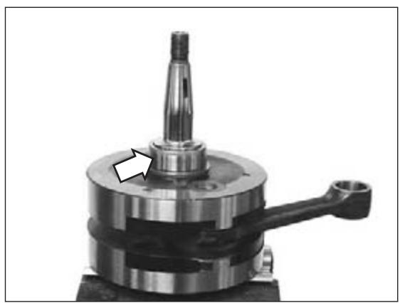
- Remove the inner ring of the crankshaft bearing -arrow using an extractor tool. Place the extractor claws below the lower lip of the inner ring.

Warning:
Do not fix the crankshaft in a bench vice by the counterweights!
- Thoroughly clean the surface where the new inner ring of the bearing will be fitted.
- Heat the inner ring of the new bearing on a heating plate, oven or similar to approx. 150^ .

Danger:
When fitting the inner ring of the crankshaft bearing, heat-resistant gloves must be worn.
- Immediately fit the inner ring of the bearing on the crankshaft, ensuring that the lower lip of the inner ring faces downwards.
- Press on the inner ring until it is completely fitted onto the crankshaft.
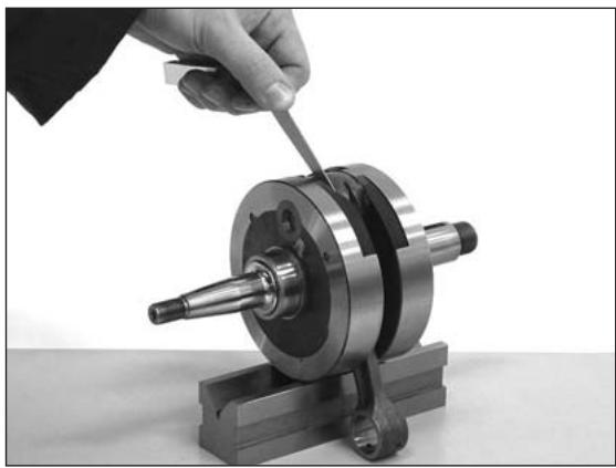
Crankshaft: outer dimension
- Measure the distance between the crankshaft counterweights at opposite points.
Maximum difference between faces
0.05 mm
Crankshaft: eccentricity
- Measure the eccentricity of the crankshaft by placing it on the bench to check the crankshaft run out ref. MFS450450025.
Maximum eccentricity
0.05 mm
Connecting rod
| i | Note:
The bearing of the connecting rod big-end is replaced together with the crankshaft journal, the connecting rod and the spacer washers. |
- Check the connecting rod small-end bearing and housing for seizure, signs of rolling and play.
- Measure the play of the connecting rod big-end by pushing it to one side and inserting a feeler gauge on the opposite side.
| Connecting rod big-end play | STD: 0.80 mm
Limit: 1.00 mm |
Piston
- Check the piston for scratches, signs of seizure and damage from overheating.
- Check the grooves of the rings (cleanliness, absence of carbon deposits, breakage, etc). If necessary, clean with a wire brush that will not damage the piston surface.
- Check that the locking pins of the rings are in their housing and are firmly seated.
- Check that there is no excess play between the rings and the piston grooves.
Piston: assembly play
| i) | Note:
The play at assembly of the piston is determined by subtracting the smallest cylinder diameter from the largest piston diameter. |
| Play of the piston at assembly | 200 cc: | STD: 0.05 mm
Limit: 0.10 mm |
| 250 cc: | STD: 0.055 mm
Limit: 0.10 mm |
| 300 cc: | STD: 0.06 mm
Limit: 0.10 mm |
04-04 SERVICE AND REPAIR OF THE ENGINE COMPONENTS
Ed: 07/05
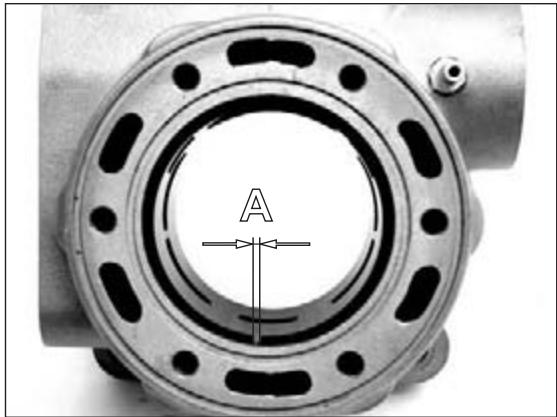
Piston: opening at the end of the ring
- Insert a piston ring in the cylinder, approximately 20mm from the upper end.
- Measure the distance between the ends of the ring -A- with a feeler gauge.
Opening at the end of 200 cc: STD: 0.3mm
the ring
250 cc: STD: 0.4 mm
Limit: 0.7 mm
STD: 0.5 mm
Limit: 0.8 mm
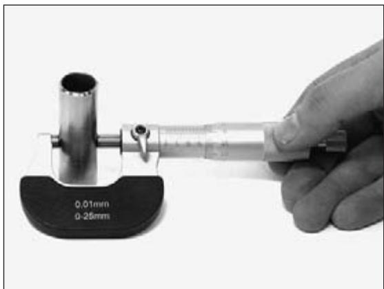
Piston pin
- Check the piston pin for seizure, signs of rolling and overheating.
- Measure the diameter of the piston with a micrometer at three different points.
Diameter of the piston pin
STD:17.994mm
Limit: 17.98 mm
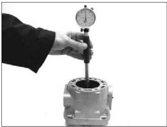
Cylinder
Cylinder: interior measurement
- Check the cylinder for scratches, signs of seizure, notches or breakage in the intake or exhaust port.
- Measure the diameter of the cylinder, approximately 20mm from the upper end and in different places, in order to obtain an exact idea of the possible ovality of the cylinder.
Cylinder diameter 200 cc: STD: 62.50 mm
Limit: 62.60 mm
250 cc: STD: 66.38 mm
Limit: 66.50 mm
300 cc: STD: 71.99 mm
Limit: 72.10 mm
Cylinder Head
- Check the cylinder support surface of the cylinder head is not damaged.
- Thoroughly clean the interior of the cylinder head, which should be free of carbon deposits.
Operation of the exhaust valve

- Screw
Tightening torque: 6 Nm
- Bearings
- Washer
- Left exhaust valve
- Screw
Tightening torque: 6 Nm
- Exhaust valve lever
- Exhaust valve bearing separator
- Bearings
- Exhaust valve bearing spacer
- Right exhaust valve
- Screw
Tightening torque: 6 Nm
- Short exhaust valve shaft
- Central exhaust valve
- Long exhaust valve shaft
- Circlip
- Pin
- Centrifugal shaft
-
Centrifugal pinion
-
Centrifugal spring
- Bearing plate
- Exhaust valve needle cage
- Centrifugal separator bearing
- Needle bearing plate
- Centrifugal hood
- Centrifugal balls
- O-ring
- Centrifugal star
- Pin
- Bolts
Tightening torque: 6 Nm
- Rod and lever unit
- Centrifugal lever shaft
- Control shaft support
- Centrifugal output lever
- Screw
Tightening torque: 6 Nm
- Needle
04-06 SERVICE AND REPAIR OF THE ENGINE COMPONENTS
Ed: 07/05
Dismantling
- Undo screws -1- and -11-.
- Take out the bearings -2- using an extractor tool together with the washer -3- and the left-side exhaust valve -4-.
- Remove the long exhaust valve shaft -12-.
- Release the right exhaust valve through the casing of the left exhaust valve -10-, the spacer -9- and the bearing -8-tapping gently with a tappet.
- Remove the short exhaust valve shaft -14- tapping the inside of the screw hole gently with a tappet either -1- or -11-.
- Remove the central exhaust valve through the cylinder exhaust port.
i
Note:
To dismantle the centrifugal mechanism, first compress the spring -19- until the pin is released -16- and then remove the mechanism.
Testing
Centrifugal shaft -17-
- Check that the centrifugal shaft does not show signs of seizure or rust. The housing -24- should slide along the shaft easily.
Centrifugal pinion -18-
- Check that the pinion does not show signs of wear in the contact area of the teeth.
Exhaust valve needle cage -21-
- Check that the needle cage does not show signs of seizure or stiffness on turning and that the plates -23- do not show signs of rolling.
Centrifugal balls -25-
- Check the condition of the centrifugal balls. They should be spherical and should not show signs of wear or contact.
Diameter of the centrifugal balls
8mm
Needle -35-
- Check that it is firmly fastened to the centrifugal output lever -33-.
Centrifugal output lever -33-
- Check that it is firmly fitted on the shaft of the centrifugal lever -31-.
- If it is necessary to remove it, mark its position with respect to the shaft of the centrifugal lever -31-, e.g. with a permanent marker.
Ed: 07/05
SERVICE AND REPAIR OF THE ENGINE COMPONENTS
04-07
Valve control shaft support -32-
- Check that the shaft of the centrifugal lever -31- moves freely within the support.
Exhaust valve bearings -2- and -11-
- Check that the exhaust valve bearings do not show signs of seizure or stiffness on turning.

Note: The exhaust valve bearings must be replaced together.
Left exhaust valve -4-, central -13- and right -10-
- Check the valves for cracks, signs of seizure or damage from overheating.
- Clean the valves of carbon deposits using a wire brush that does not damage the surface of the valves.
Short exhaust valve shaft -14- and long shaft -12-
- Check the shafts for cracks, signs of seizure or damage from overheating.
- Clean the shafts of carbon deposits using a wire brush that does not damage the surface of the valves.
Central exhaust valve assembly position -13-
- Fit the central exhaust valve with the curved surface facing the inside of the exhaust port.
04-08 SERVICE AND REPAIR OF THE ENGINE COMPONENTS
Ed: 07/05
Crankcase
- Allen key 6x70
Tightening torque: 6 Nm
- Left crankcase (outer side)
- Cylinder studs
- Crankcase centring bushing
- Water intake sump plug
- Fibre washer 14x20x2
- Oil filler cap
- Copper washer
- Left crankcase (inner side)
- Central crankcase gasket
- Copper washer 8x12x1
- Allen key 8x14
Tightening torque: 15 Nm
- Oil cap O-ring 12x2
- Oil drain cap with magnet
Tightening torque: 9 Nm
- Right crankcase
- Clutch cover gasket
- Clutch cover
- Allen key 6x25
Tightening torque: 6 Nm
Ed: 07/05
SERVICE AND REPAIR OF THE ENGINE COMPONENTS
04-09
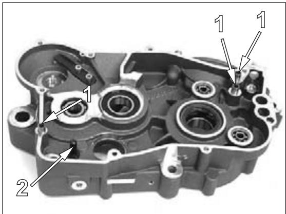
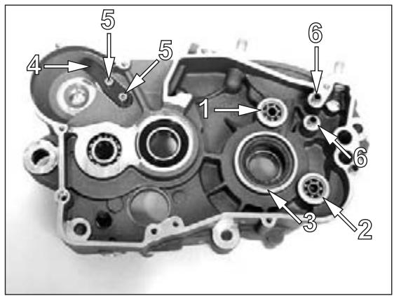
Right half crankcase, inner side
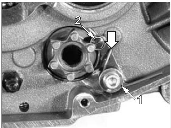
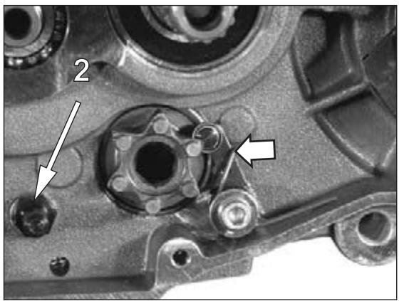
- Remove the centring bushings -1- and the centring pin of the selector spring -2-.
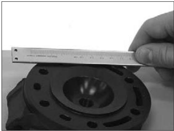
- Before making any repairs to the right half crankcase, check the deformation to the same in the entire perimeter using a feeler gauge, both on the inside and the outside.
Maximum deformation of half crankcase 0.05 mm

Note:
To remove the bearings of the right half crankcase it should be heated to approximately 150^ using a heating plate, oven or similar. When it is hot, only a standard extractor tool is required, a soft metal or wooden rod, to completely remove the bearings. In exceptional cases it may be necessary to use a press to dislodge the bearings.
- Take out the right crankcase seals using a seal extractor or by carefully levering with a screwdriver.

Note:
All gaskets, seals and O-rings should be replaced whenever the engine is dismounted partially or completely.
- Place the right half crankcase on a heating plate and heat to approximately 150^ .

Danger:
When handling the crankcase after heating it, heat-resistant gloves should be used to protect hands.
04-10 SERVICE AND REPAIR OF THE ENGINE COMPONENTS
Ed: 07/05
- Remove the right crankcase bearings.
Crankshaft bearing -1-
- Remove the ball bearing from the crankshaft by pressing from the outside of the crankcase inwards.
- Fit the new ball bearing in the crankcase housing. The stamped face of the bearing should face the inside of the crankcase.
- Press on the new ball bearing until it fits level with the inner surface of the crankcase.
Primary cam bearing -2-
- Remove the ball bearing from the primary cam by pressing from the outside of the crankcase inwards.
- Fit the new ball bearing in the crankcase housing. The closed face of the bearing should face the outside of the crankcase.
- Press down on the bearing until it fits completely in the right crankcase housing.
| Warning:
When removing and fitting the ball bearing take care not to apply excessive pressure on the casing area of the bearings. If too much pressure is applied the crankcase may be damaged! |
Secondary cam bearing -3-
- Remove the ball bearing from the secondary cam by pressing from the outside of the crankcase inwards.
- Fit the new ball bearing in the crankcase housing. The stamped face of the bearing should face the inside of the crankcase.
- Press down on the bearing until it fits completely in the right crankcase housing.
| Warning:
When removing and fitting the ball bearing take care not to apply excessive pressure on the casing area of the bearings. If too much pressure is applied the crankcase may be damaged! |
Desmodromic bearing -4-
- Remove the needle bearing from the desmodromic by pressing from the outside of the crankcase inwards.
- Fit the new needle bearing in the crankcase housing. The stamped face of the bearing should face the inside of the crankcase.
- Press down on the bearing until it fits completely in the right
| Engine | 200 cc / 250 cc / 300 cc | G |
| EC ENDUCROSS WORKSHOP MANUAL |
| Ed: 07/05 | SERVICE AND REPAIR OF THE ENGINE COMPONENTS | 04-11 |
crankcase housing.
| Warning:
Be careful when removing and fitting the needle bearings so as not to put too much pressure on the bearing housings. If too much pressure is applied, the crankcase could be damaged! |
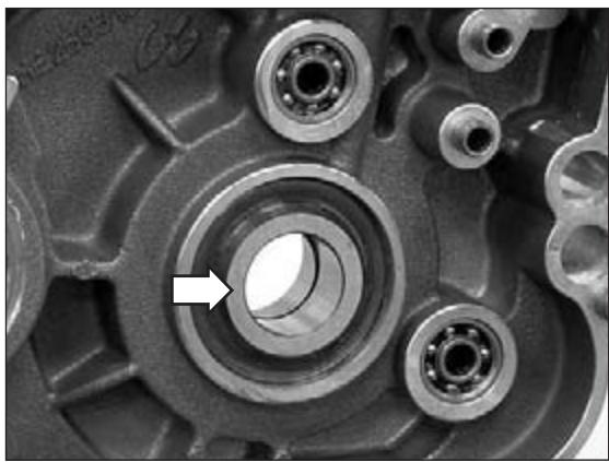
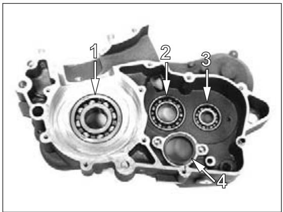
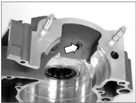
- Check the opening for lubricating the crankshaft bearing -arrow-. It should be free of obstruction and clean.
Right half crankcase, outer side
| i | Note:
To remove the bearings of the right half crankcase it should be heated to approximately 150 °C using a heating plate, oven or similar.
When it is hot, only a standard extractor tool is required, a soft metal or wooden rod, to completely remove the bearings. In exceptional cases it may be necessary to use a press to dislodge the bearings. |
- Take out the right crankcase seals using a seal extractor or by carefully levering with a screwdriver.
| i) | Note:
All gaskets, seals and O-rings should be replaced whenever the engine is dismounted partially or completely. |
- Place the right half crankcase on a heating plate and heat to approximately 150^ .
04-12 SERVICE AND REPAIR OF THE ENGINE COMPONENTS
Ed: 07/05
!
Danger:
When handling the crankcase after heating it, heat-resistant gloves should be used to protect hands.
- Remove the right crankcase bearings.
Centrifugal shaft bearing -1-
- Remove the ball bearing from the centrifugal pinion using a bearing extractor ( max. 8mm) from outside the half crankcase.
- Fit the new ball bearing in the crankcase housing. The closed face of the bearing should face the inside of the opening of the casing.
- Press down on the bearing until it fits completely in the right crankcase housing.
Pinion shaft bearing of water pump -2-
- Remove the ball bearing from the water pump pinion shaft using a bearing extractor ( max. 8mm) from outside the half crankcase.
- Fit the new ball bearing in the crankcase housing. The closed face of the bearing should face the inside of the opening of the casing.
- Press down on the bearing until it fits completely in the right crankcase housing.
Crankshaft seal -3-
- Fit the new crankshaft seal in the crankcase housing. The seal lip should face the outside of the crankcase.
- Press down on the seal with a rod until it fits completely in the right crankcase housing.
!
Warning:
When fitting the seal take care not to damage the seal lip!
Starter ratchet plate -4-
- Remove the starter ratchet plate by undoing the screws -5-.
Ed: 07/05
SERVICE AND REPAIR OF THE ENGINE COMPONENTS
04-13
- Fit the plate by applying thread-lock on the screws -5-Centring bushings -6-
- Check the existence and condition of the centring bushings -6-.
- Replace non-existent centring bushings where necessary.

Note:
If there are no centring bushings, a correct seal is not guaranteed when the crankcases are fitted.
Left half crankcase, inner side
- Before making any repairs to the left half crankcase, check the deformation to the same in the entire perimeter on the inside using a feeler gauge.
Maximum deformation of half crankcase
0.05 mm

Note:
To remove the bearings of the left half crankcase it should be heated to approximately 150^ using a heating plate, oven or similar. When it is hot, only a standard extractor tool is required, a soft metal or wooden rod, to completely remove the bearings. In exceptional cases it may be necessary to use a press to dislodge the bearings.
- Take out the left crankcase seals using a seal extractor or by carefully levering with a screwdriver.

Note:
All gaskets, seals and O-rings should be replaced whenever the engine is dismounted partially or completely.
- Place the left half crankcase on a heating plate and heat to approximately 150^ .
04-14 SERVICE AND REPAIR OF THE ENGINE COMPONENTS
Ed: 07/05
| ! | Danger: When handling the crankcase after heating it, heat-resistant gloves should be used to protect hands. |
- Remove the left crankcase bearings.
Crankshaft bearing -1-
- Remove the ball bearing from the crankshaft using a bearing extractor (max. 38mm ) from the inside of the crankcase inwards.
- Fit the new ball bearing in the crankcase housing. The stamped face of the bearing should face the inside of the crankcase.
- Press on the new ball bearing until it fits level with the inner surface of the crankcase.
Primary cam bearing -2-
- Remove the ball bearing from the primary cam by pressing from the outside of the crankcase inwards.
- Fit the new ball bearing in the crankcase housing. The stamped face of the bearing should face the outside of the crankcase.
- Press down on the bearing until it fits completely in the left crankcase housing.
Warning:
When removing and fitting the ball bearing take care not to apply excessive pressure on the casing area of the bearings. If too much pressure is applied the crankcase may be damaged!
Secondary cam bearing -3-
- Remove the ball bearing from the secondary cam by pressing from the outside of the crankcase inwards.
- Fit the new ball bearing in the crankcase housing. The stamped face of the bearing should face the inside of the crankcase.
- Press down on the bearing until it fits completely in the right crankcase housing.
| Engine | 200 cc / 250 cc / 300 cc | G |
| EC ENDUCROSS WORKSHOP MANUAL |
| Ed: 07/05 | SERVICE AND REPAIR OF THE ENGINE COMPONENTS | 04-15 |
| Warning:
Be careful when removing and fitting the needle bearings so as not to put too much pressure on the bearing housings. If too much pressure is applied, the half crankcase could get damaged! |
Desmodromic bearing -4-
- Remove the needle bearing from the desmodromic using a bearing extractor ( max. 25mm ) from the inside of the crankcase inwards.
- Fit the new needle bearing in the crankcase housing. The stamped face of the bearing should face the inside of the opening of the casing.
- Press down on the bearing until it fits completely in the left crankcase housing.
| Warning:
When removing and fitting the needle bearing take care not to apply excessive pressure on the casing area of the bearings. If too much pressure is applied the crankcase may be damaged! |
- Check the opening for lubricating the crankshaft bearing - arrow-. It should be free of obstruction and clean.
Left crankcase, outer side
| Note:
All gaskets, seals and O-rings should be replaced whenever the engine is dismounted partially or completely. |

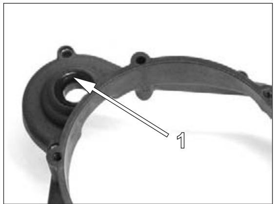
Crankshaft seal -1-
- Fit the new crankshaft seal in the crankcase housing. The seal lip should face the outside of the crankcase.
- Press down on the seal with a rod until it fits completely in the left crankcase housing.
| Warning:
When fitting the seal take care not to damage the seal lip! |
04-16
SERVICE AND REPAIR OF THE ENGINE COMPONENTS
Ed: 07/05
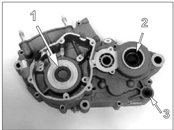
Output shaft seal -2-
- Fit the new crankshaft seal in the crankcase housing. The seal lip should face the outside of the crankcase.
- Press down on the seal with a rod until it fits completely flat in the left crankcase housing.
!
Warning:
When fitting the seal take care not to damage the seal lip!
Selector shaft seal -3-
- Fit the new selector shaft seal in the crankcase housing. The seal lip should face the outside of the crankcase.
- Press down on the seal with a rod until it fits completely in the left crankcase housing.
!
Warning:
When fitting the seal take care not to damage the seal lip!
Clutch cover
- Before any repairs to the clutch cover check the deformation on the inside using a feeler gauge.
Maximum deformation of clutch cover
0.05 mm

Note:
To remove the bearings of the clutch cover it should be heated to approximately 150^ using a heating plate, oven or similar. When it is hot, only a standard extractor tool is required, a soft metal or wooden rod, to completely remove the bearings. In exceptional cases it may be necessary to use a press to dislodge the bearings.
- Take out the clutch cover seals using a seal extractor or by carefully levering with a screwdriver.
| Engine | 200 cc / 250 cc / 300 cc | G |
| EC ENDUCROSS WORKSHOP MANUAL |
| Ed: 07/05 | SERVICE AND REPAIR OF THE ENGINE COMPONENTS | 04-17 |
| i) | Note:
All gaskets, seals and O-rings should be replaced whenever the engine is dismounted partially or completely. |
- Place the clutch cover on a heating plate and heat to approximately 150^ .
| Danger:
When handling the crankcase after heating it, heat-resistant gloves should be used to protect hands. |
- Remove the clutch cover bearings.

Centrifugal shaft bearing -1-
- Remove the ball bearing from the centrifugal shaft using a bearing extractor ( max. 8 mm) from the inside of the clutch cover.
- Fit the new ball bearing in the clutch cover housing. The closed face of the bearing should face the inside of the opening of the casing.
- Press down on the bearing until it fits completely in the clutch cover housing.
Pinion shaft bearing of water pump -2-
- Remove the ball bearing from the pinion shaft of the water pump using a bearing extractor ( max. 10mm ) from the inside of the clutch cover.
- Fit the new ball bearing in the clutch cover housing. The closed face of the bearing should face the inside of the opening of the casing.
- Press down on the bearing until it fits completely in the clutch cover housing.
04-18
SERVICE AND REPAIR OF THE ENGINE COMPONENTS
Ed: 07/05
Starter shaft seal -1-
- Fit the new starter shaft seal in the clutch cover housing. The seal lip should face the outside of the clutch cover.
- Press down on the seal with a rod until it fits completely in the clutch cover housing.
!
Warning:
When fitting the seal take care not to damage the seal lip!
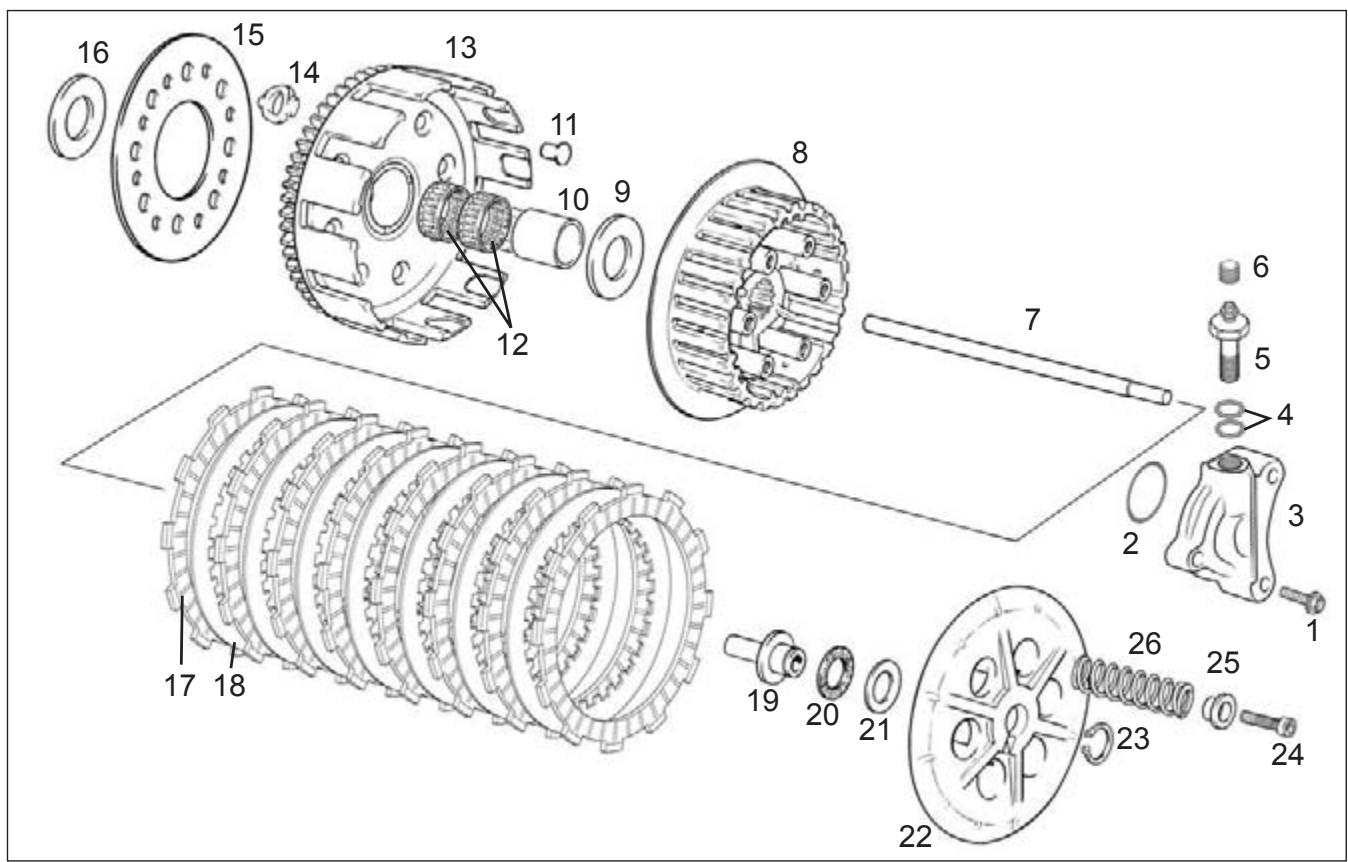
Clutch
- Screw 6x20
Tightening torque: 6 Nm
- Clutch pump O-ring
- Hydraulic clutch calliper
- Line washer
- Bleeder
- Bleeder cap
- Clutch rod
- Clutch hub
- Washer
- Clutch housing bushing
- Clutch housing rivets
- Clutch housing bearing
- Clutch housing crown
- Rubber silentblock
- Washer clutch crown
- Clutch housing washer 22.1x42x2.8
- Covered clutch disc
- Iron clutch disc
- Clutch rod
- Needle bearing
- Needle plate
- Clutch press
-
Circlip 15
-
Allen key 6x20
Tightening torque: 6 Nm
- Clutch spring bushing
- Clutch spring
04-20 SERVICE AND REPAIR OF THE ENGINE COMPONENTS
Ed: 07/05
Clutch spring -26-
- Check the condition of the springs and their length.
Length of the springs
Min. 45.7 mm
Limit: 44 mm

Note:
The clutch springs are replaced as a set.
Clutch press -22-
- Check the condition and the contact surface with the clutch discs for scratches and excessive wear.
Bearing -20- and rod -19-
- Check the clutch bearing and the rod for seizure, signs of rolling and play.

Covered clutch discs -17-
- Check the thickness of the covered clutch discs.
Thickness of the covered clutch disc
STD: 2.75 to 2.85 mm
Limit: 2.68 mm
Iron clutch discs -18-
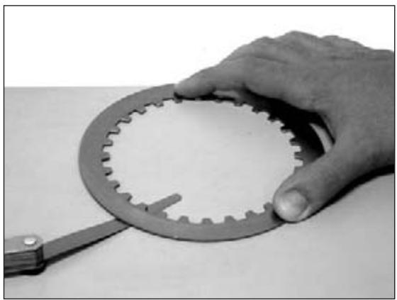
- Check the condition of the clutch disc for scratches and warping or deformation.
Maximum deformation of the iron clutch plate
0.05 mm
Ed: 07/05
SERVICE AND REPAIR OF THE ENGINE COMPONENTS
04-21
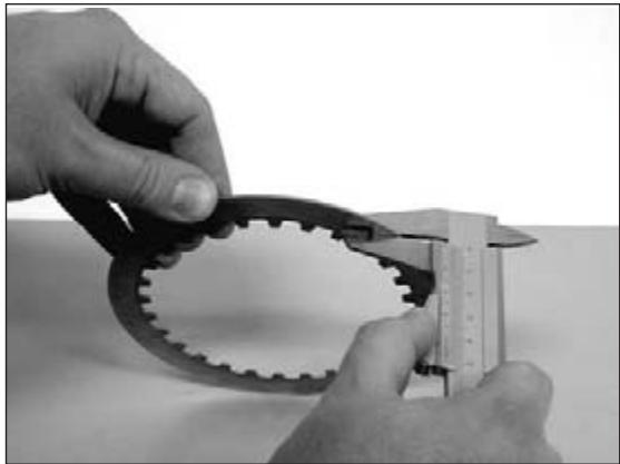
- Check the thickness of the iron clutch disc.
Thickness of the clutch disc
Limit: 1.45 to 1.55 mm
Limit: 1.40 mm
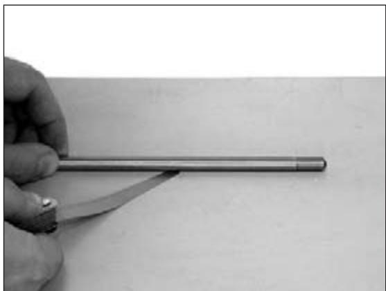
Clutch rod -7-
- Check the clutch rod deformation.
Maximum deformation of the clutch rod
0.05 mm
Clutch hub -8-
- Check that the clutch disc housings -arrow- are not out of line due to excessive wear.
- Check the condition and the contact surface -1- with the clutch discs for scratches and excessive wear.
- Check that the oil circulation openings -2- are free from dirt and metal particles.
Clutch housing crown -13-
- Check the contact surface of the bearing -1- for seizure, signs of rolling and play.
- Check on both sides that the lubrication grooves -2- are free from dirt and metal particles.
- Check there is no play between the housing -3- and the crown -4-.
- Check that the clutch disc housings -arrow- are not out of line due to excessive wear.
Clutch housing bearings -12-
- Check the clutch housing bearings and the bushing for seizure, signs of rolling and play.
04-22 SERVICE AND REPAIR OF THE ENGINE COMPONENTS
Ed: 07/05
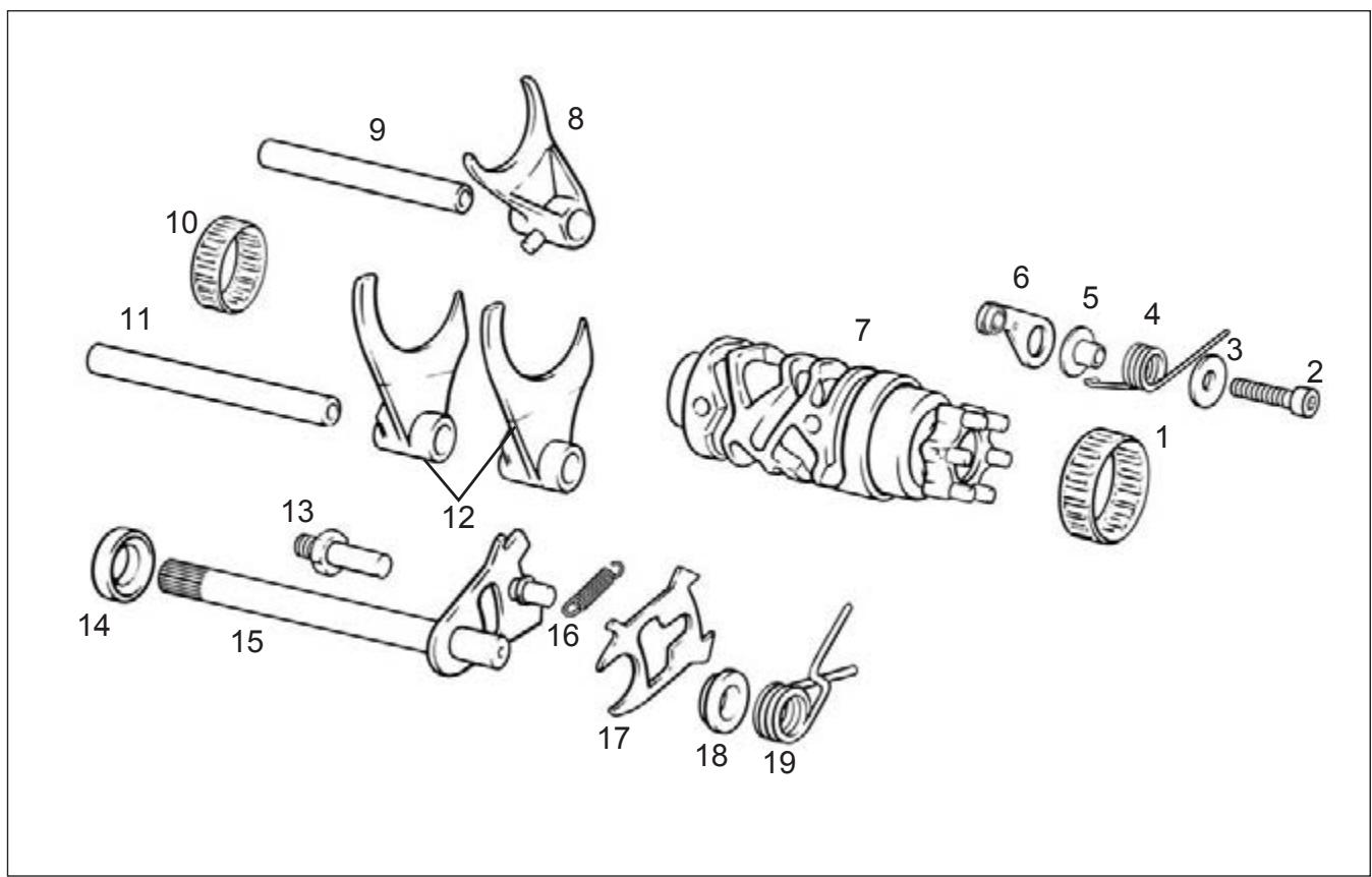
Gearshift mechanism
- Desmodromic bearing
- Allen key 6x25x8.8
Tightening torque: 6 Nm
- Flat washer 6x16x1.5
- Gear locking spring
- Gear lock plate bushing
- Gear lock
- Desmodromic
- Fork V-VI
- Short fork shaft
- Desmodromic bearing HK3512
- Long fork shaft
- Forks I-II-III-IV
- Centring pin selector shaft
- Selector shaft bushing
- Selector shaft
- Scorpion spring
- Scorpion
- Scorpion guide bushing
- Selector spring
Ed: 07/05
SERVICE AND REPAIR OF THE ENGINE COMPONENTS
04-23
Selector shaft -15-
- Check that the selector shaft shows no signs of excessive wear or contact marks.
- Check that the selector rod bushing -14- is in good condition and without excess play.
Scorpion guide bushing -18-
- Check that the guide bushing does not show signs of excess wear in the contact area with the scorpion -17-.

Selector shaft assembly
- Insert the selector shaft bushing -14- at the end. The assembly position should be with the conical side -arrow- facing the side opposite the scorpion -17-.
- Insert the scorpion guide bushing -18- in the end of the selector shaft -15-.
- Insert the scorpion -17- in the selector shaft guide.
- Place the selector spring -19- on the shaft support and support the lower foot (straight foot) on the end.
- Using pliers, pass the upper foot (curved foot) over the end until it is supported on the opposite side to the lower foot.
- Insert the ends of the scorpion spring -16- on the supports of the selector shaft -15-and of the scorpion -17-.
Gear lock -6-
- Check that the bearing at the end of the lock is in good condition, turns easily and does not show signs of excess play.
Desmodromic -7-
- Check the rolling tracks of the desmodromic bearings -1- for seizure, signs of rolling and play.
- Check the inside of the desmodromic channels for dirt and particles and make sure the channels are not excessively worn.
Short -9- and long -11-fork shaft
- Check the fork shafts for deformation.
- Check the shafts for signs of wear or grooving. The forks should slide easily across the shafts.
Maximum deformation of the fork shafts
0.05 mm
Forks -8- and -12-
- Check that the fork is neither damaged nor bent.
- Check that the interior of the fork ride opening shows no signs of wear or grooving.
04-24
SERVICE AND REPAIR OF THE ENGINE COMPONENTS
Ed: 07/05
- Check the play between the fork and its housing in the pinion.
Play between the fork and. its housing in the pinion
STD: 0.15 mm
Limit: 0.25 mm
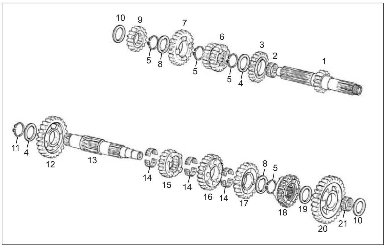
Gears
- Primary shaft
- Needle bearing K25-29-10
- Primary pinion V
- Washer 25.2x31.5x1
- Circlip D25 recessed
- Primary pinion III and IV
- Primary pinion VI
- Serrated washer 31.5x1
- Primary gear II
- Shift washer 18x31.5x0.7
- Circlip D25
- Secondary pinion II
- Secondary shaft
- Needle cage bearings KD22x25x9.8
- Secondary pinion VI
- Secondary pinion III
- Secondary pinion IV
- Secondary pinion V
- Washer 20.8x29x1
- Secondary pinion I
- Needle bearings K20-24-10
04-26 SERVICE AND REPAIR OF THE ENGINE COMPONENTS
Ed: 07/05
- Check the contact surface of the bearings for seizure, signs of rolling and play.
- Check the pinion teeth for wear or breakage.
- Check the pinions and tracks are free of dirt.
- Check that the lubrication grooves which include some pinions are free of dirt and metal particles.
- After dismounting the parts of the cans, clean thoroughly and replace all the circlips.
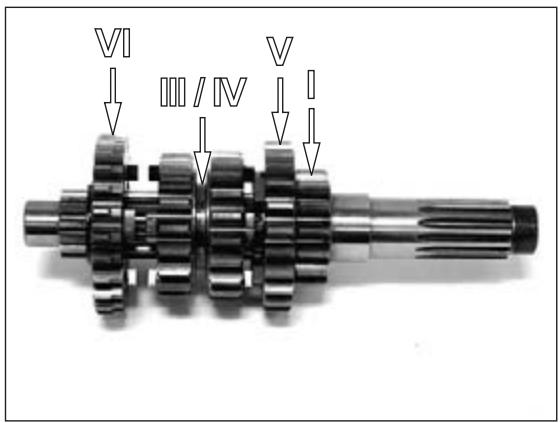
Primary cam -1-
- Thoroughly lubricate all the bearings when assembling.

Note: The assembly order of the pinions is: V - III / IV - VI speeds
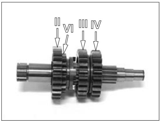
Secondary cam -16-
- Thoroughly lubricate all the bearings when assembling.

Note: The assembly order of the pinions is: II - VI - III - IV speeds
| Engine | 200 cc / 250 cc / 300 cc | G |
| EC ENDUCROSS WORKSHOP MANUAL |
| Ed: 07/05 | SERVICE AND REPAIR OF THE ENGINE COMPONENTS | 04-27 |

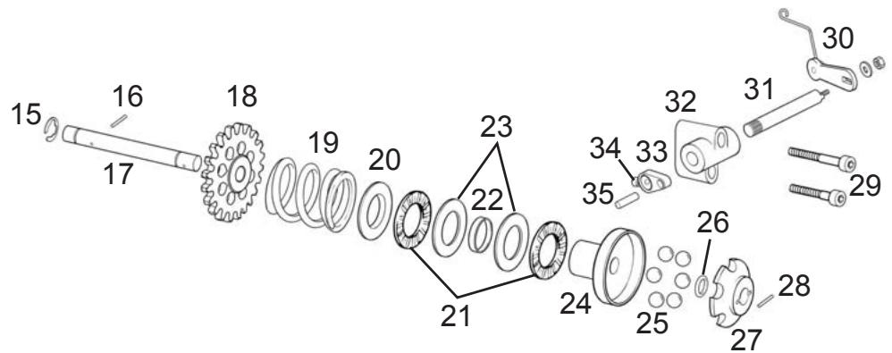
Starter mechanism
- Circlip D15
- Washer 24x15.15x0.8
- Interior starter pinion
- Starter ratchet plate
- Allen screws 5x15
Tightening torque: 6 Nm
- Starter ratchet spring
- Starter ratchet
- Circlip D20
- Stop washer 27x20.2x1
- Starter pinion
- Starter shaft
- Washer 20x40x1
- Starter spring
- Starter shaft centring bushing
04-28 SERVICE AND REPAIR OF THE ENGINE COMPONENTS
Ed: 07/05
Starter shaft -11-
- Check that the starter shaft teeth show no signs of excessive wear or contact marks.
- Check the play of the shaft in the casing housing.
- Check that the interior lubrication openings are clean and free of particles.
Ratchet -7-
- Check that the ratchet teeth do not show signs of excessive wear.
Starter pinion -10-
- Check that the pinion does not show signs of excessive wear or play.
- Check that the starter pinion teeth show no signs of excessive wear or contact marks.
Interior pinion -3-
- Check that the pinion does not show signs of excessive wear or play.
- Check that the lubrication channels are clean and free of particles.
- Check that the interior bushing of the pinion shows no signs of scratching or excessive wear.
| Engine | 200 cc / 250 cc / 300 cc | Gg |
| EC ENDUCROSS WORKSHOP MANUAL |
| Ed: 07/05 | SERVICE AND REPAIR OF THE ENGINE COMPONENTS | 04-29 |
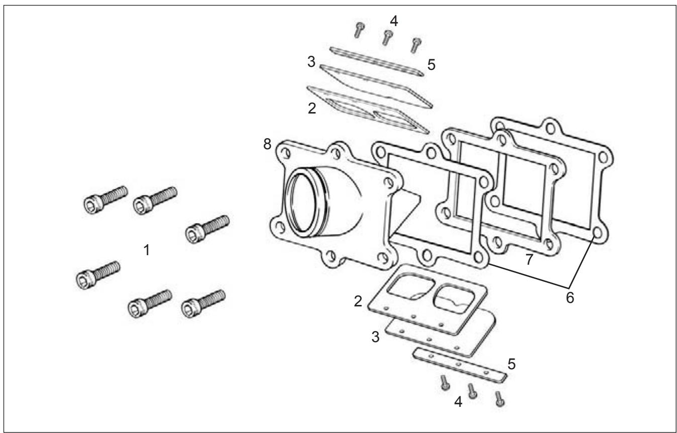
Reed valve
- Allen screws 6x16
Tightening torque 6 Nm
- Lower reed
- Upper reed
- Screws
- Reed support
- Reed valve gaskets
- Reed spacing plate
- Reed valve
04-30 SERVICE AND REPAIR OF THE ENGINE COMPONENTS
Ed: 07/05
Reeds -2- and -3-
- Check the reeds for cracks or splitting and for signs of ageing.
- Check that the reeds sit firmly one on top of another and are dry.
Reed spacer plate -7-
- Check that the spacer -7- does not have any deformed surfaces.
Reed valve -8 -
- Check that the supporting surfaces of the reeds are in perfect condition.
| Engine | 200 cc / 250 cc / 300 cc | G |
| EC ENDUCROSS WORKSHOP MANUAL |
| Ed: 07/05 | SERVICE AND REPAIR OF THE ENGINE COMPONENTS | 04-31 |
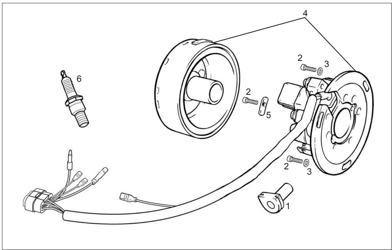
Ignition
- Ignition rubber top
- Allen screw 5x20
Tightening torque: 6 Nm
- Flat washer 5x12x1.5
- Magnetic flywheel Kokusan FP-8009 Multispark
- Ignition Centring
- Spark plug
04-32
SERVICE AND REPAIR OF THE ENGINE COMPONENTS
Ed: 07/05
Ignition rubber top -1-
- Check that the ignition rubber top is in good condition.
Magnetic flywheel Kokusan -4-
- Carry out the following tests using a multi-tester.
| Measurement | Colour of wires | Resistance |
| Impulse coil | Red - Green | 100 Ω +/- 20% |
| Exciter | Black/Red - Red/White | 12.7 Ω +/- 20% |
| Charge coil | Yellow - Earth | 0.67 Ω +/- 20% |
| White - Yellow | 0.16 Ω +/- 20% |

Note:
All measurements must be taken at a temperature of 20^ . Otherwise significant errors may occur in the measurement values.
Spark plug -6-
- Check that the spark plug shows no signs of knocks or cracks
- Check that the spark plug is free of carbon deposits and particles.
- Check that the electrode is not over worn or burnt
- Check the electrode distance with a feeler gauge.
Electrode distance
0.7 to 0.8 mm
| Engine | 200 cc / 250 cc / 300 cc | G |
| EC ENDUCROSS WORKSHOP MANUAL |
| Ed: 07/05 | ASSEMBLING THE ENGINE | 05-01 |
| i | Notes:
All the engine parts must be perfectly clean and in optimum conditions for commencing assembly.
Before assembly, apply engine oil to all the moving and sliding parts. |
- Place the right half crankcase on the workbench.
Assembling the crankshaft
- Lubricate the crankshaft bearing in the crankcase.
- Insert the crankshaft in the crankcase bearing.
- On the opposite side of the crankcase fit the O-ring and then the crankshaft seal bushing with the recessed side facing outwards.
Assembling the selector rod and gears from the gearbox
- Lubricate the bearings of the gear cam and of the desmodromic in the crankcase.
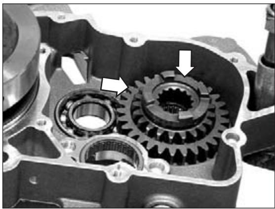
- Place the pinions of I and V gear -arrows-, the needle bearing and the adjustment washers in the crankcase.
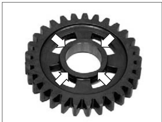

Note:
The 1st gear pinion should be positioned with the four notches -arrows- facing the crankcase.
05-02 ASSEMBLING THE ENGINE
Ed: 07/05
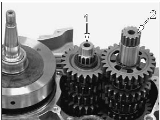
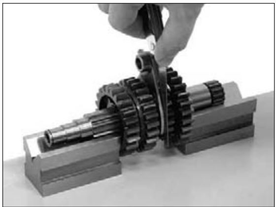
- Carefully place together the gear caps of the primary -1- and secondary -2- shafts.
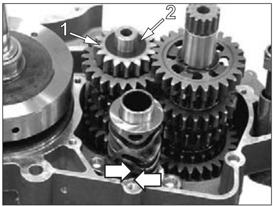
- Place the pinion of 2^nd gear -1- and the adjustment washer
-2- on the primary gear cam.
- Fit the desmodromic in the crankcase lining it up with the marks -arrows- made when dismounting.
- Position the forks -1- in the grooves of the gears and at the same time in the desmodromic grooves.
- Next slide the shafts -2- (short) and -3- (long) across the forks to their housing in the crankcase.

Note:
Check the transmission works correctly by turning the desmodromic by hand. Place the transmission gears in neutral position.
Joining the crankcases
- Turn the bench so that the left-hand half of the crankcase is facing upwards and remove the nut fastening the engine to the bench.
- Check that the contact surfaces of the left and right crankcases are perfectly clean
- Fit the centring bushings in the left crankcase.
- Position the new gasket.
- Fit the right crankcase and gently tap with a plastic hammer until the two surfaces are joined together.

| i | Note:
Remember to place the small gasket in the upper part of the crankcase -arrow-. |
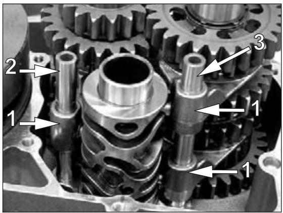
- Place the screws in the position shown in the diagram.
Screws -1: 70 mm
Screws -2: 60 mm
Screws -3: 65 mm
- Adjust all the screws slightly and then tighten in diagonal pairs, starting at the centre.
Tightening torque: 10 Nm
- Check that the crankshaft and the transmission shaft turn smoothly, if this is not the case try to release the turn by tapping them with a plastic hammer.
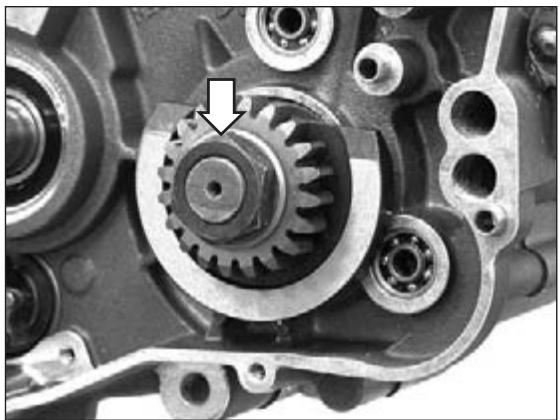
- Fit the chain pinion hub on the shaft.
- Put the nut fastening the engine to the bench back again.
- Check that there are no traces of the half crankcase sealant on the cylinder support surface.
Fitting the reed valve
- Remove the remains of the crankcase gasket on the support surface of the reed box.
- Place the reed box in its housing with the new gaskets.
- Tighten the screws -arrows-.
Tightening torque: 10 Nm
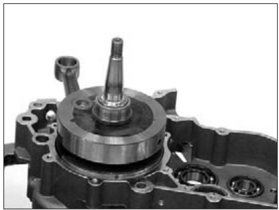
Fit the dual-mass flywheel of the crankshaft

Note:
The 200 cc engine is not fitted with a flywheel. The crankshaft pinion is fastened with a hexagonal screw.
- Fit the crankshaft pin, the flywheel, the crankshaft pinion, the bevelled washer and the nut on the crankshaft.

Note:
The locking nut of the crankshaft is tightened to the left!
05-04 ASSEMBLING THE ENGINE
Ed: 07/05
- Lock the rotation of the crankshaft pinion and tighten the nut -arrow-.
Tightening torque: 40 Nm
Assembling the gear selector unit
- Place the gear locking unit with the spring -arrow- slack and tighten the arrow -1 -. Use thread lock.
Tightening torque: 6 Nm
Tightening torque: 15 Nm
- Insert the selector shaft bushing and fit the complete selector shaft -arrow-.
Ed: 07/05
ASSEMBLING THE ENGINE
05-05
Assembling the starter pinion unit
- Lubricate the housing of the starter shaft in the crankcase.
- Insert the starter unit, ensuring that the ratchet is located between the plate and the casing.
- Place the spring -1- in the opening in the crankcase using pliers.
- Check that the centring bushing of the starter spring is positioned correctly.
- Lubricate the bearing of the inner pinion of the starter.
- Fit the inner pinion of the starter, the spacing washer and the circlip -2-.
Assembling the centrifugal operating system of the exhaust valve
- Lubricate the centrifugal shaft bearing in the crankcase.
- Fit the centrifugal mechanism -2- in the crankcase.
- Fit the support -1- ensuring that the output lever is correctly located in the groove of the mechanism.
- Tighten the screws -arrows-. Use thread lock.
Tightening torque: 10 Nm
- Fit the water pump shaft and pinion.
Assembling the clutch
- Check that the primary shaft is clean and particle-free.
- Fit the washer -3-, the bushing -2- and the clutch housing bearings -1-.
- Lubricate the clutch housing bearings.

- Fit the clutch housing and then the washer -arrow-.

Note:
When fitting the clutch hub note the assembly position with respect to the mark made when dismounting.
05-06 ASSEMBLING THE ENGINE
Ed: 07/05
- Fit the clutch hub, the new lock washer and the fastening nut.
- Hold the clutch hub down and tighten the fastening nut. Use thread lock.
Tightening torque: 40 Nm

- Close the catch of the lock washer -1-.
- Check that the clutch discs are perfectly clean and lubricate all the discs.
- Insert the iron discs and the covered discs alternately in the clutch hub, beginning and ending with a covered disc.
- Lubricate the rod bearing and fit the clutch press -2-.
- Place the screws -1- with their bushings and springs and tighten them in stages in diagonal pairs. Use thread lock. Tightening torque: 10 Nm
Assembling the cylinder and cylinder head
- Check that the piston and pin are clean.
- Lubricate the connecting rod small-end bearing.
- Position the piston with the arrow marked on the head facing the exhaust port.

Note:
Before fitting the pin circlip cover the crankcase opening with a clean cloth.
Ed: 07/05
ASSEMBLING THE ENGINE
05-07

-
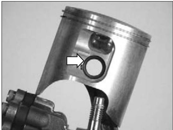
Insert the pin through the piston and the bearing of the connecting rod small-end, and then fit the new circlip -arrow-.
-
Fit the piston rings with the manufacturer's inscription facing upwards.
- Fit the gaskets at the foot of the cylinder.
- Carefully fit the cylinder, making sure that the rings are centred with the locking pins of the piston grooves.
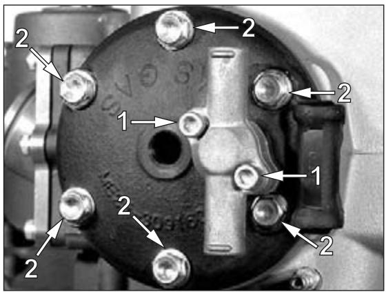
- Fit the four cylinder nuts and adjust slightly.
- Adjust the four nuts at the foot of the cylinder in diagonal pairs.
Tightening torque: 25 Nm
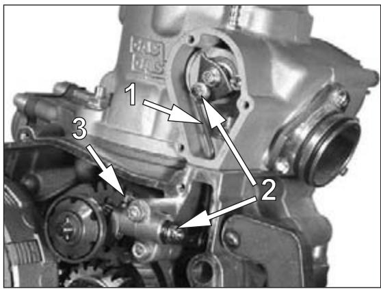
- Place the exhaust valve operating rod -1-. Replace the nuts
-2- with new ones and tighten them.
Tightening torque: 8 Nm
- Test the working of the entire exhaust valve system.

Note:
If it is necessary to make adjustments, loosen the screw of the centrifugal mechanism lever
-3- and place the lever-rod unit in the desired position.
- Fit the new O-rings on the upper part of the cylinder.
- Check that the support surface of the cylinder head is perfectly clean.

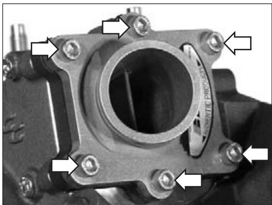
- Place the cylinder head and tighten the screws -2- in diagonal pairs. Use thread lock.
Tightening torque: 25 Nm
- Check that the support surface of the thermostat cover is perfectly clean.
- Fit the thermostat cover with a new gasket and tighten the screws -1-. Use thread lock.
Tightening torque: 10 Nm
05-08 ASSEMBLING THE ENGINE
Ed: 07/05
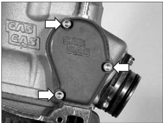
- Fit the right cover of the exhaust valve with a new gasket and tighten the screws -arrows-.
Tightening torque: 8 Nm
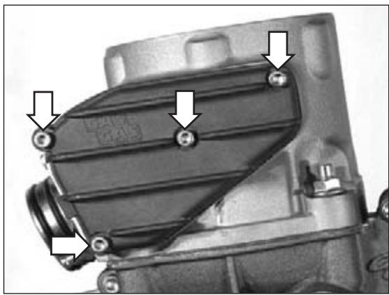
- Fit the left cover of the exhaust valve and tighten the screws -arrows-.
Tightening torque: 8 Nm

Fitting the clutch cover
- Fit the new gasket of the clutch cover .
- Fit the clutch cover and tighten the screws in diagonal pairs.
Screws -1: 30 mm
Screws -2: 35 mm
Screws -3: 55 mm
Tightening torque: 10 Nm
- Fit the clutch disc cover with a new gasket and tighten the screws in diagonal pairs.
Screws 4:25 mm
Screws 5:75 mm
Tightening torque: 10 Nm
Assembling the water pump
- Fit the new seal of the water pump -arrow- on the clutch cover.
Ed: 07/05
ASSEMBLING THE ENGINE
05-09

- Position the turbine -1- of the water pump and fit the fastening screw -2-.
- Block the rotation of the turbine and tighten the screw -2-. Use thread lock.
Tightening torque: 6 Nm

- Fit the cover of the water pump and tighten the screws -arrows-.
Tightening torque: 6 Nm
Assembling the ignition
- Fit the pin from the crankshaft.
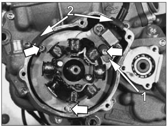
- Position the ignition stator and the screws -arrows-, noting the location of the ignition centring washer -1-.
- Tighten the screws -arrows-. Use thread lock.
Tightening torque: 8 Nm
- Ensure that the rubber tops -2- are correctly fitted.
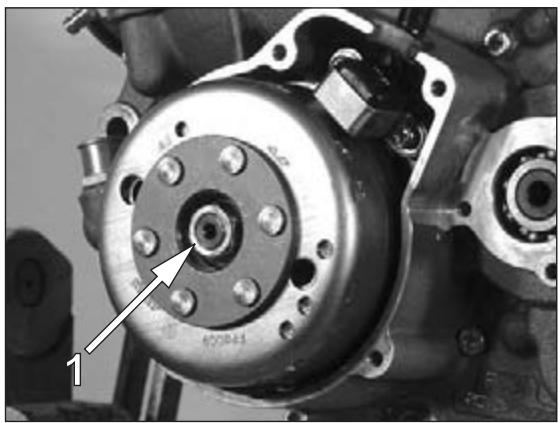
- Fit the magnetic flywheel and tighten the nut -1-. Use thread lock.
Tightening torque: 40 Nm
05-10 ASSEMBLING THE ENGINE
Ed: 07/05
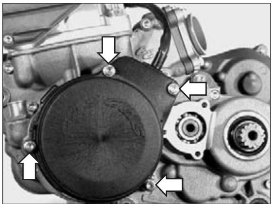
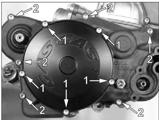
- Fit the ignition cover with a new gasket and tighten the screws -arrows-.
- Fit the spark plug in the cylinder head.
Warning:
The spark plug should always be handthreaded to the limit and then adjusted with a spark plug wrench without over-tightening! Tightening torque: 27 Nm
| Engine | 200 cc / 250 cc / 300 cc | G |
| EC ENDUCROSS WORKSHOP MANUAL |
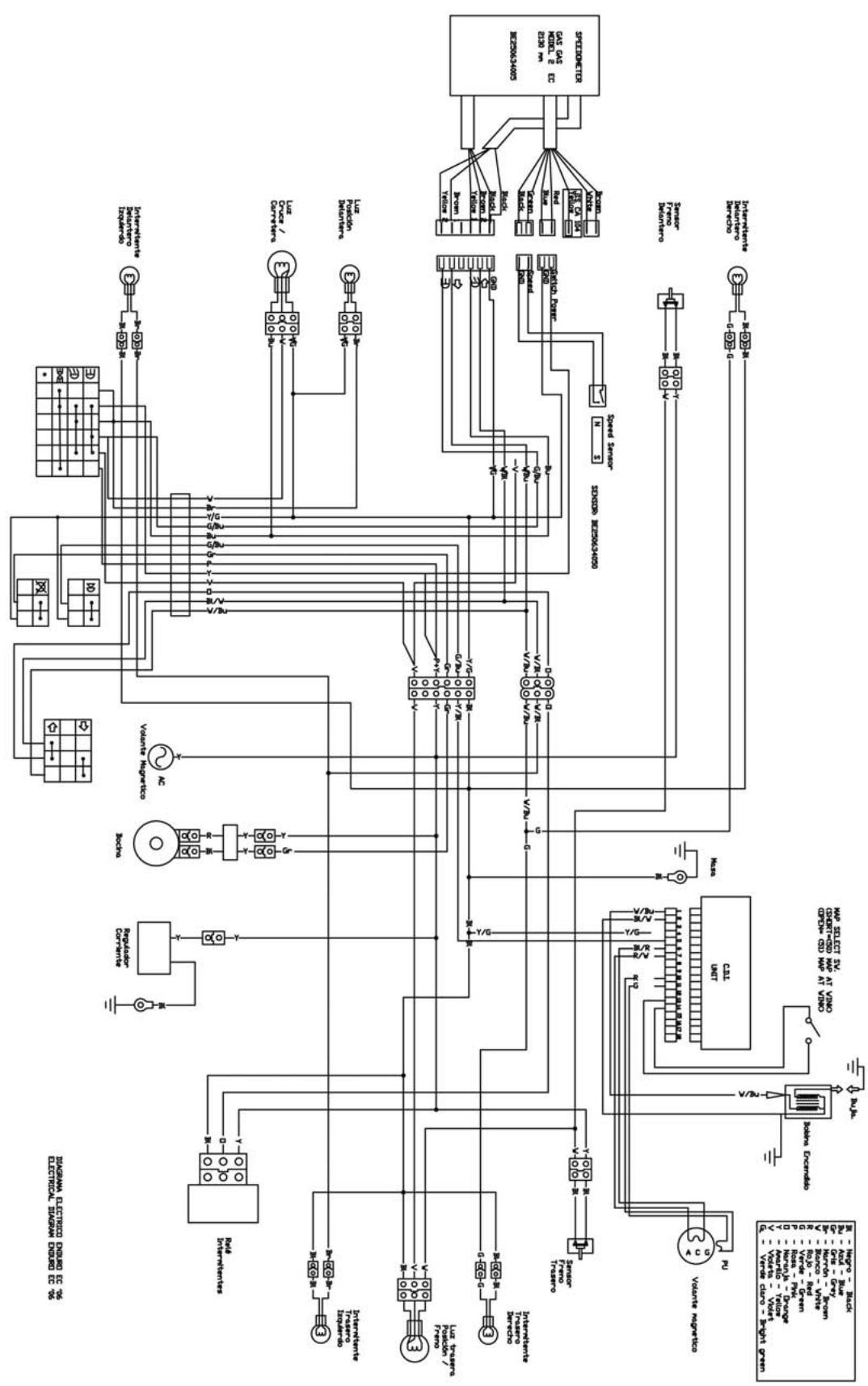
| Ed: 07/05 | ELECTRICAL SCHEMAS | 06-01 |

C/ Unicef, 17 - Poligon Industrial Torremirona - 1719 Salt (Girona) SPAIN
TEL +34 902 47 62 54 / FAX + 34 902 47 61 60
www.gasgasmotos.es