
HC-2400 TYPE 1E - Hedge trimmers ECHO - Free user manual and instructions
Find the device manual for free HC-2400 TYPE 1E ECHO in PDF.
| Brand | ECHO |
| Model | HC-2400 TYPE 1E |
| Product type | Gas hedge trimmer |
| Length | 1280 mm |
| Width | 240 mm |
| Height | 210 mm |
| Weight (dry) | 5.2 kg |
| Engine | 2-stroke, single cylinder, 23.6 cc, air-cooled |
| Fuel | Fuel/oil mixture 50:1 (89 octane unleaded gasoline) |
| Tank capacity | 0.5 L |
| Blade type | Double reciprocating blade, single-edge (length 994 mm, pitch 35 mm) |
| Idle speed | 3000 rpm |
| Full load speed | 11,000 - 12,000 rpm |
| Spark plug | BPM-7A (gap 0.65 mm) |
| Carburetor | Zama C1U |
| Clutch | Centrifugal |
| Gear ratio | 1:5.13 (Type 1E) |
| Starting system | Auto-rewind starter |
| Safety equipment | Hand guard, emergency stop, throttle lock |
| Recommended maintenance | Air filter cleaning, fuel filter replacement, blade lubrication, cooling system cleaning |
| Included accessories | T-wrench, 2-stroke oil bottle (2.6 oz), blade guide, manuals |
| Certification | Complies with EPA Phase 2, California Emission standards |
Frequently Asked Questions - HC-2400 TYPE 1E ECHO
User questions about HC-2400 TYPE 1E ECHO
0 question about this device. Answer the ones you know or ask your own.
Ask a new question about this device
Download the instructions for your Hedge trimmers in PDF format for free! Find your manual HC-2400 TYPE 1E - ECHO and take your electronic device back in hand. On this page are published all the documents necessary for the use of your device. HC-2400 TYPE 1E by ECHO.
USER MANUAL HC-2400 TYPE 1E ECHO
The muffler or catalytic muffler and surrounding cover may become extremely hot.
Always keep clear of exhaust and muffler area, otherwise serious personal injury may occur.

WARNING

The engine exhaust from this product contains chemicals known to the State of California to cause cancer, birth defects or other reproductive harm.

WARNING DANGER
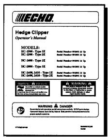
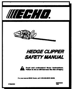
Read rules for safe operation and all instructions carefully. ECHO provides this Operator's Manual and a Safety Manual. Both must be read and understood for proper and safe operation.
INTRODUCTION
Welcome to the ECHO family. This ECHO product was designed and manufactured to provide long life and on-the-job-dependability. Read and understand this manual and the SAFETY MANUAL you found in the same package. You will find both easy to use and full of helpful operations tips and SAFETY messages.
WARNING

DANGER
Read rules for safe operation and instructions carefully. ECHO provides an Operator's Manual and a Safety Manual. Both must be read and understood for proper and safe operation.
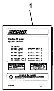
contains specifications and information for operation, starting, stopping, maintenance, storage and assembly specific to this product.
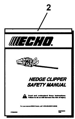
THE SAFETY MANUAL
explains possible hazards involved with the use of Hedge Clippers and what measures you should take to make their use safer.
TABLE OF CONTENTS
Introduction 2
- The Operator's Manual 2
- The Safety Manual 2
Manual Safety Symbols and Important Information .... 3
Safety 3
- Decals 3
- International Symbols 4
Equipment 4
-Fuel 5 - Personal Condition and Safety Equipment 5
- Safe Operation 7
- ExtendedOperation/ExtremeConditions 8
Description 9
- Contents 9
- Emissions Control 9
Specifications 12
- ModelsHC-1500/1600/2000/2400/2410 12
Assembly 12
Pre-Operation 13
-Fuel 13
EquipmentCheck 15
- Determine Operation Area 15
Operation 16
-StartingColdEngine 16
-StartingWarmEngine 17
Copyright © 2002 By Echo, Incorporated
All Rights Reserved.
- Stopping Engine 18
Maintenance 18
- Skill Levels 18
- Maintenance Intervals 19
- Air Filter 20
-FuelFilter 20
-Spark Plug 21
- Cooling System 21
- Exhaust System 22
- Carburetor Adjustment Emission 23
- Carburetor Adjustment Non Emission 24
-Lubrication 25
- Blade Stiffener Remove/Install 27
- Sharpening Blades 28
Troubleshooting 29
Storage 30
Servicing Information 32
- Parts 32
-Service 32
-Warranty Card. 32 - Additional or Replacement Manuals 32
- Manual Ordering Instructions 32
Specifications, descriptions and illustrative material in this literature are as accurate as known at the time of publication, but are subject to change without notice. Illustrations may include optional equipment and accessories, and may not include all standard equipment.
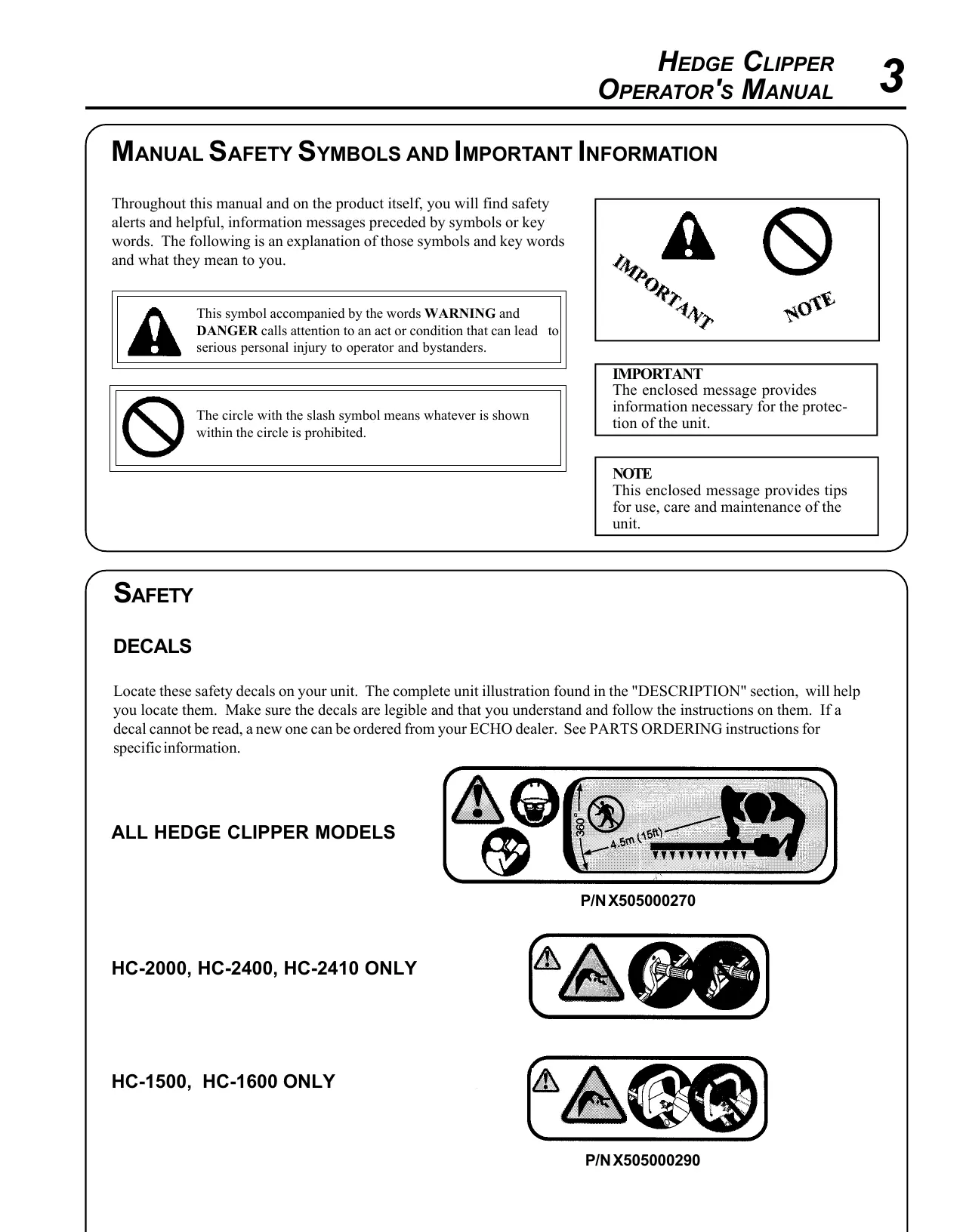
MANUAL SAFETY SYMBOLS AND IMPORTANT INFORMATION
Throughout this manual and on the product itself, you will find safety alerts and helpful, information messages preceded by symbols or key words. The following is an explanation of those symbols and key words and what they mean to you.

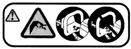
This symbol accompanied by the words WARNING and DANGER calls attention to an act or condition that can lead to serious personal injury to operator and bystanders.

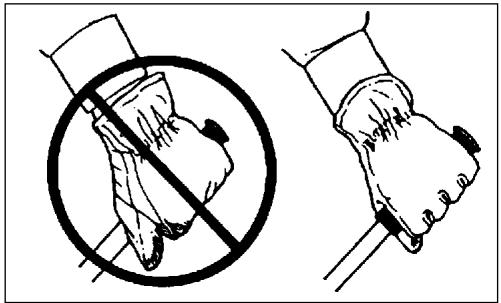
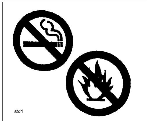
The circle with the slash symbol means whatever is shown within the circle is prohibited.


IMPORTANT
The enclosed message provides information necessary for the protection of the unit.
NOTE
This enclosed message provides tips for use, care and maintenance of the unit.
SAFETY
DECALS
Locate these safety decals on your unit. The complete unit illustration found in the "DESCRIPTION" section, will help you locate them. Make sure the decals are legible and that you understand and follow the instructions on them. If a decal cannot be read, a new one can be ordered from your ECHO dealer. See PARTS ORDERING instructions for specific information.
ALL HEDGE CLIPPER MODELS
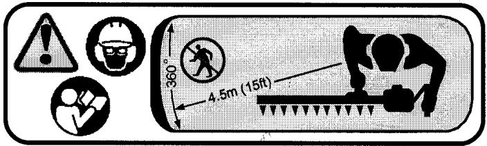
P/N X505000270
HC-2000, HC-2400, HC-2410 ONLY
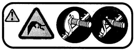
HC-1500, HC-1600 ONLY
P/NX505000290
INTERNATIONAL SYMBOLS
| Symbol form/shape | Symbol description/application | Symbol form/shape | Symbol description/application |
| Read and understand owners manual. | Fuel and oil mixture | ||
| Wear eyes, ears and head protection | Finger Severing | ||
| STOP | Emergency stop | Hot Surface | |
| Wear hand protec-tion. Use two handed. | DO NOT smoke near fuel. | ||
| Engine choke control. | Ignition ON OFF O | Ignition ON/OFF | |
| Chain lubrication | Do not operate without guards in place. |
| Symbol form/shape | Symbol description/application | Symbol form/shape | Symbol description/application |
| L | Carburetor adjustment - Low speed mixture | H | Carburetor adjustment - High speed mixture |
| ! | Safety/Alert | T | Carburetor adjustment - Idle speed |
| 4 | Avoid all power lines. This unit is not insulated against electrical current. | Do not operate clos-er than 15 M (50 ft.) from electrical haz-ards. | |
| Plan retreat path from falling objects. | Primer bulb | ||
| DO NOT allow flames or sparks near fuel. | Wear slip resistant foot wear. | ||
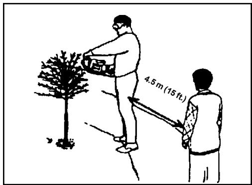
| Keep bystanders at least 4.5 meters (15 feet) away. | |||
EQUIPMENT
Before operation a complete check of the unit must be performed;
- Check unit for loose/missing nuts, bolts and screws. Tighten and/or replace as needed.
- Inspect fuel lines, tank and area around carburetor for fuel leaks. DO NOT operate unit if leaks are found.
- Never adjust blades when the engine is operating.
- Inspect hand guard for damage. Replace if damaged or missing.
- Check that the blade assembly is firmly attached and in safe operating condition. Dull, loose or damaged blades should not be used.
- ECHO, INC. will not be responsible for the failure of cutting devices or accessories which have not been tested and approved by ECHO for use with this unit.
FUEL
WARNING

DANGER
Fuel is VERY flammable. Use extreme care when mixing, storing or handling or serious personal injury may result.
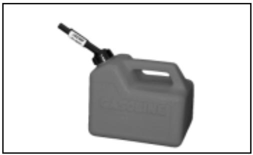
- Use an approved fuel container.
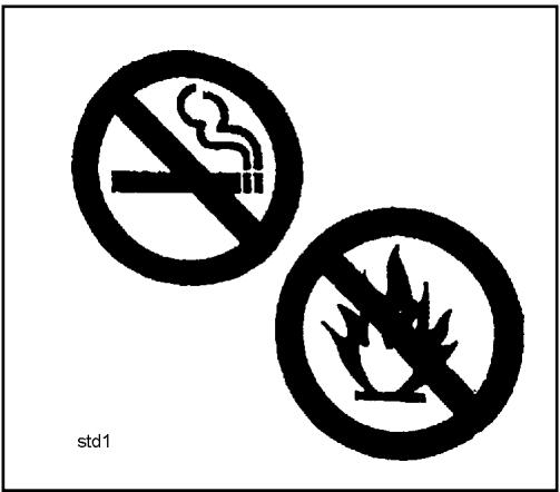
- DONOT smoke near fuel.
- DO NOT allow flames or sparks near fuel.
- Fuel tanks/cans may be under pressure. Always loosen fuel caps slowly allowing pressure to equalize.
- NEVER refuel a unit when the engine is HOT!
- NEVER refuel a unit with the engine running.
- DO NOT fill fuel tanks indoors. ALWAYS fill fuel tanks outdoors over bare ground.
- Securely tighten fuel cap after refueling.
- Inspect for fuel leakage. If fuel leakage is found, do not start or operate unit until leakage is repaired.
IMPORTANT
Spilled fuel is a leading cause of hydrocarbon emissions. Some states may require the use of automatic fuel shut-off containers to reduce fuel spillage. Contact your ECHO dealer for ordering information.
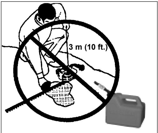
After Refueling;
- Wipe any spilled fuel from the unit.
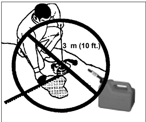
- Move at lease 3m (10 ft.) from refueling location before starting the engine.
After use;
- DO NOT store a unit with fuel in its tank. Leaks can occur. Return unused fuel to an approved fuel storage container.
PERSONAL CONDITION AND SAFETY EQUIPMENT
WARNING

DANGER
Hedge Clipper users risk injury to themselves and others if the hedge clipper is used improperly and or safety precautions are not followed. Proper clothing and safety gear must be worn when operating a hedge clipper.
Physical Condition --
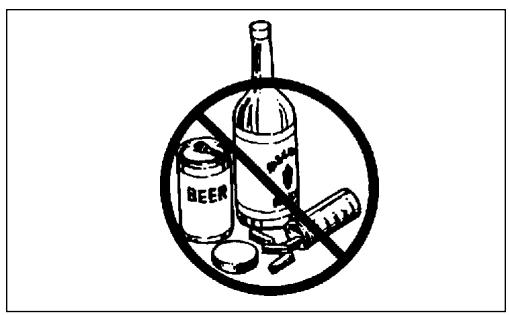
Your judgment and physical dexterity may not be good:
- if you are tired or sick,
- if you are taking medication,
- if you have taken alcohol or drugs
Operate unit only if you are physically and mentally well.
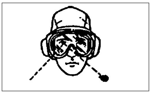
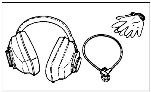
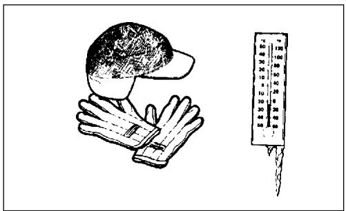
Eye Protection --
Eye protection that meet ANSI Z87.1 or CE requirements must be worn whenever you operate the Hedge Clipper.
Hand Protection --
Wear no-slip, heavy duty work gloves to improve your grip on the handles. Gloves also reduce the transmission of machine vibration to your hands.
Hearing Protection --
Wear hearing protection. ECHO recommends wearing hearing protection whenever unit is used.
Proper Clothing --
Wear snug fitting, durable clothing;
- Pants should have long legs, shirts with long sleeves.
- DONOTWEARSHORTS,
DONOT WEARTIES, SCARFS, JEWELRY.
Wear protective hair covering to contain long hair.
Wear sturdy work shoes with nonskid soles;
- DONOT WEAR OPENTOED SHOES.
- DONOTOPERATEUNITBAREFOOTED.
Wear no-slip, heavy duty work gloves.
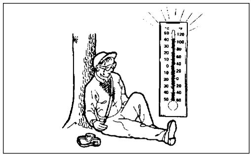
Hot Humid Weather --
Heavy protective clothing can increase operator fatigue which may lead to heat stroke. Delay heavy work until temperature drops.
SAFE OPERATION
Determine Operation Area
- Do not operate this product indoors or in inadequately ventilated areas.
- Review the area to be trimmed. Look for hazards that could contribute to unsafe conditions.
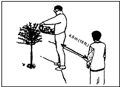
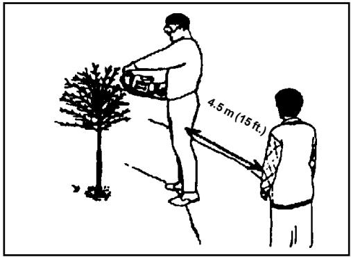
- Spectators and fellow workers must be warned, and children and animals prevented from coming nearer than 4.5m (15 ft.) while the Hedge Clipper is in use.
- Provide all users of this equipment with the Operator's Manual and instructions for Safe Operation.
Operation
Use Proper Clothing & Equipment
- Before starting the unit, equip yourself and any other person working within the 4.5m (15 ft.) Safety Zone with the required Protective Equipment and clothing.
Keep a Solid Stance
- Maintain footing and balance at all times. Do not stand on slippery, uneven or unstable surfaces. Do not work in odd positions or on ladders. Do not over reach.
Keep a Firm Grip
- Hold the front and rear handles with both hands, with thumbs and fingers encircling the handles.
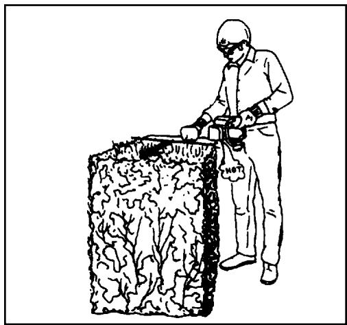
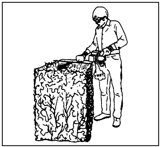
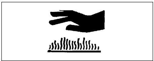
Avoid Hot Surfaces
- During operation, the complete unit, especially the power head, muffler area and cutting attachment may become very hot, too hot to touch. Avoid contact during and immediately after operation.

1
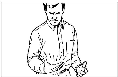
It is believed that a condition called Raynaud's Phenomenon, which affects the fingers of certain individuals may be brought about by exposure to vibration and cold. Exposure to vibration and cold may cause tingling and burning sensations followed by loss of color and numbness in the fingers. The following precautions are strongly recommended because the minimum exposure which might trigger the ailment is unknown.
- Keep your body warm, especially the head, neck, feet, ankles, hands and wrists.
- Maintain good blood circulation by performing vigorous arm exercises during frequent work breaks and also by not smoking.
- Limit the hours of operation. Try to fill each day with jobs where operating the trimmer or other hand-held power equipment is not required.
- If you experience discomfort, redness and swelling of the fingers followed by whitening and loss of feeling, consult your physician before further exposing yourself to cold and vibration.
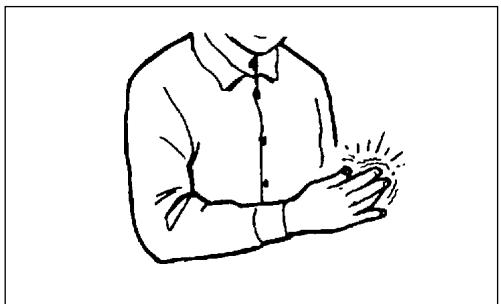
Repetitive Stress Injuries
It is believed that overusing the muscles and tendons of the fingers, hands, arms and shoulders may cause soreness, swelling, numbness, weakness and extreme pain in those areas. Certain repetitive hand activities may put you at a high risk for developing a Repetitive Stress Injury (RSI). An extreme RSI condition is Carpal Tunnel Syndrome (CTS), which could occur when your wrist swells and squeezes a vital nerve that runs through the area. Some believe that prolonged exposure to vibration may contribute to CTS. CTS can cause severe pain for months or even years.
To reduce the risk of RSI/CTS, do the following:
- Avoid using your wrist in a bent, extended or twisted position. Instead try to maintain a straight wrist position. Also, when grasping, use your whole hand, not just the thumb and index finger.
- Take periodic breaks to minimize repetition and rest your hands.
- Reduce the speed and force with which you do the repetitivemovement.
- Do exercises to strengthen the hand and arm muscles.
- Immediately stop using all power equipment and consult a doctor if you feel tingling, numbness or pain in the fingers, hands, wrists or arms. The sooner RSI/CTS is diagnosed, the more likely permanent nerve and muscle damage can be prevented.
DESCRIPTION
The ECHO product you purchased has been factory pre-assembled for your convenience.
After opening the carton, check for damage. Immediately notify your retailer or ECHO Dealer of damaged or missing parts. Use the contents list to check for missing parts.
CONTENTS
1 - Hedge Clipper Assembly
1- Operators Manual
1 - Safety Manual
1 - Warranty Statement
1 - Warranty Registration Card
1 - Plastic Bag
- T-Wrench
- Bottle 2.6 oz. 2-Cycle Oil
1 - BladeCover
EMISSION CONTROL -Emissions Models
The emission control system for this engine is EM (Engine Modification).
IMPORTANT ENGINE INFORMATION
ENGINE FAMILY: 2EHXS.0214RA DISPLACEMENT: 21.2cc ENGINE COMPLIANCE PERIOD: 300 Hours THIS ENGINE MEETS U.S. EPA PH2 EMISSION REGULATIONS FOR SMALL NONROAD ENGINES. REFER TO OWNER'S MANUAL FOR MAINTENANCE SPECIFICATIONS AND ADJUSTMENTS.

KoRtz
COFF
Emission Control Label (located on Engine) (EXAMPLE ONLY, information on label varies by FAMILY).


HC-1500, 1600
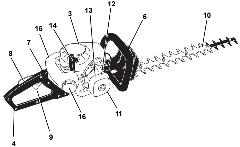
- OPERATOR'S MANUAL - Read and understand this manual before operation. Keep manual in a safe location for future reference, i.e., operation, maintenance, storage and specifications.
- SAFETY MANUAL - Read and understand this manual before operation. Keep manual in a safe location of safe operating techniques.
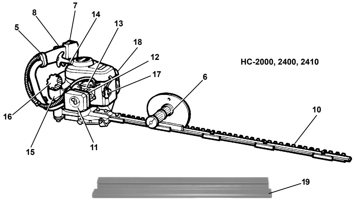
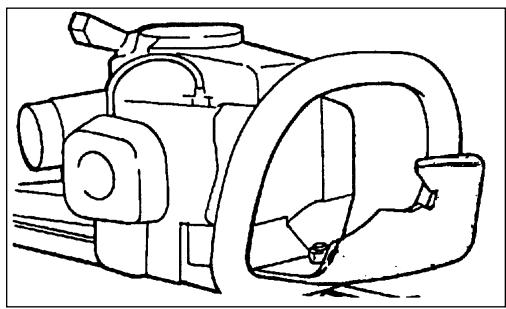
- POWER HEAD - Factory Assembled to the gear housing assembly. Includes the Engine, Clutch, Fuel System, Ignition System and Recoil Starter.
- REAR HANDLE - HC-1500, 1600. Contains the Stop Switch, Throttle Lockout and Throttle Trigger.
- LEFTHANDREARHANDLE -HC-2000, 2400, 2410. Contains the Stop Switch, Throttle Lockout and Throttle Trigger.
- FRONTHANDLE/GUARD- HC-1500, 1600. Comfortable, textured finish provides anti-slip grip for front hand. Guard protects hand from the blades. Warning decals are located on guard. HC-2000, 2400 and HC-2410. Right Hand Handle, Rubber anti-slip grip, guard protects hand from the blades. Warning decals are located on guard.
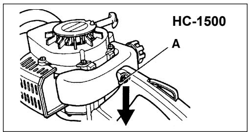
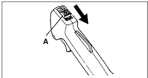
- STOPSWITCH- HC-1500. "TOGGLE SWITCH" located on the left side of the rear handle. Move switch UP to RUN, DOWN to STOP. HC-1600, HC-2000, 2400, 2410 "SLIDE SWITCH" mounted on top of the left hand rear handle. Move switch FORWARD to RUN, BACK to STOP.
- THROTTLE TRIGGER LOCKOUT - This lever must be depressed before Throttle Trigger can be activated.
- THROTTLE TRIGGER - Spring loaded to return to idle when released. Trigger Lockout must be depressed fully before Throttle Trigger will move. During acceleration, depress gradually for best operating technique.
- BLADES - Double reciprocating blades mounted to a blade support bar. Models HC-1500, HC-1600 are double sided blades, meaning they are capable of cutting on either side of the blade. All other models are single sided.
- AIRCLEANER-Contains replaceable filter element.
- PRIMER BULB - Pumping primer bulb before starting engine draws fresh fuel from the fuel tank priming the carburetor for starting. Pump primer bulb until fuel is visible and flows freely in the clear fuel tank return line. Pump bulb an additional 4 or 5 times.
- CHOKE - The choke control lever is located on the top of the choke case. Move to "COLD START" to close the choke for Cold Starting. Move to "RUN" position to open choke.
- RECOIL STARTER HANDLE - Pull handle slowly until recoil starter engages, then quickly and firmly. DO NOT pull rope all the way out or allow the handle to snap back, damage to the starter will occur.
- FUEL TANK - Contains fuel and fuel filter.
- FUEL TANK CAP - Covers and seals fuel tank opening.
- SPARKPLUG-Provides spark to ignite fuel mixture.
- MUFFLER/SPARK ARRESTOR - The muffler controls the exhaust noise while the spark arrestor prevents hot, glowing particles of carbon from leaving the muffler where they could possibly start a fire.
- BLADE COVER - Used to cover blades during transportation or storage. Remove blade cover before using unit.
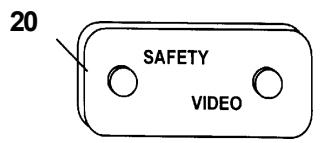
- SAFETYVIDEO - (Not included with unit) P/N 99922202800 English version only is available at a cost of $5.00 from ECHO, INC. or any authorized ECHO dealer. The video overviews safety precautions and proper operating techniques and is supplemental to the Safety Manual. Read and understand the Safety Manual for complete information on safe operation.
SPECIFICATIONS
| MODEL | HC-1500 1E HC-1500 2E | HC-1600 1E | HC-2000 1E | HC-2400 1E HC-2400 2E | HC-2410 1E HC-2410 2E |
| Length | 960mm (37.8 in.) | 1133mm (44.6 in.) | 990mm (39.0 in.) | 1030mm (40.6 in.) | 1280mm (50.4 in.) |
| Width | 225mm (8.9 in.) | 240mm (9.4 in.) | 240mm (9.4 in.) | 240mm (9.4 in.) | 240mm (9.4 in.) |
| Height | 190mm (7.5 in.) | 200mm (7.9 in.) | 230mm (9.1 in.) | 210mm (8.3 in.) | 210mm (8.3 in.) |
| Weight, dry | 4.4 kg (9.7 lb.) | 5.3 kg (11.7 lb.) | 5.2 kg (11.4 lb.) | 5.2 kg (11.4 lb.) | 5.2 kg (11.4 lb.) |
| Type of Engine | Air cooled, two-stroke, single cylinder, gasoline engine | ||||
| Displacement | 21.2 cc (1.29 cu.in.) | 21.2 cc (1.29 cu.in.) | 21.2 cc (1.29 cu.in.) | 23.6 cc (1.44 cu.in.) | 23.6 cc (1.44 cu.in.) |
| Bore | 32.2 mm (1.27 in.) | 32.2 mm (1.27 in.) | 32.2 mm (1.27 in.) | 34.0 mm (1.34 in.) | 34.0 mm (1.34 in.) |
| Stroke | 26.0 mm (1.02 in.) | 26.0 mm (1.02 in.) | 26.0 mm (1.02 in.) | 26.0 mm (1.02 in.) | 26.0 mm (1.02 in.) |
| Exhaust System | Spark Arrestor Muffler | ||||
| Carburetor | Zama C1U | ||||
| Ignition System | Flywheel Magneto, Capacitor discharge ignition | ||||
| Spark Plug | BPM-7A (Gap 0.65 mm (0.026 in.) | ||||
| Fuel | Mixed Fuel - gasoline and oil | ||||
| Fuel/Oil Ratio | 50:1 Ratio using ECHO Hi-Performance, two-stroke air cooled engine oil | ||||
| Gasoline | 89 Octane Unleaded. Do not use fuel containing methyl alcohol, more than 10% ethyl alcohol or 15% MTBE. | ||||
| Oil | ECHO Hi-Performance, two-stroke air cooled engine oil | ||||
| Fuel Tank Capacity | 0.3 lit. (10.1 fl. oz) | 0.5 lit. (17.0 fl. oz) | 0.5 lit. (17.0 fl. oz) | 0.5 lit. (17.0 fl. oz) | 0.5 lit. (17.0 fl. oz) |
| Starter System | Automatic Recoil Starter | ||||
| Clutch | Centrifugal Type | ||||
| Gear Case Ratio | 1:5.88 | 1:5.88 | 1:5.88 | 1:5.13 1E 1:3.9 2E | 1:5.13 1E 1:3.9 2E |
| Cutter (Double Reciprocating Blade) | Double Edge | Double Edge | Single Edge | Single Edge | Single Edge |
| Length | 573mm (22.6 in.) | 721mm (28.4 in.) | 750mm (29.5 in.) | 750mm (29.5 in.) | 994mm (39.1 in.) |
| Pitch | 35mm (1.4 in.) | ||||
| Height | 21mm (0.83 in.) | 21mm (0.83 in.) | 24mm (0.94 in.) | 24mm (0.94 in.) | 24mm (0.94 in.) |
| Idle Speed (RPM) | 3000 | ||||
| Wide Open Throttle (RPM) | 11,000 - 12,000 | ||||
ASSEMBLY HC MODELS ARE PRE-ASSEMBLED IN THE BOX.
Tools Required: None
Parts Required: None
PRE-OPERATION
FUEL
Fuel Requirements
Gasoline - Use 89 Octane [ + M2] (mid grade or higher) gasoline known to be good quality. Gasoline may contain up to 15% MTBE (methyl tertiary-butyl ether). Gasohol containing methyl (wood) alcohol is NOT approved.
Two Stroke Oil - A two-stroke engine oil meeting ISO-L-EGD (ISO/CD 13738) and J.A.S.O. FC Standards, must be used. Echo brand Premium 50:1 oil meets these standards. Engine problems due to inadequate lubrication caused by failure to use an ISO-L-EGD and J.A.S.O. FC certified oil, such as Echo Premium 50:1 Two-stroke Oil, will void the two-stroke engine warranty. (Emission related parts only are covered for two years, regardless of two-stroke oil used, per the statement listed in the EPA Phase I/ California Emission Defect Warranty Explanation.)
IMPORTANT
Echo Premium 2-Stroke Oil may be mixed at 50:1 ratio for application in all Echo engines sold in the past regardless of ratio specified in those manuals.
Mixing Instructions
- Fill an approved fuel container with half of the required amount of gasoline.
- Add 2-stroke oil to gasoline.
- Close container and shake to mix oil with gasoline.
- Add remaining gasoline and remix.
- Install fuel container cap and wipe any spilled fuel from container and surrounding area.
Handling Fuel
WARNING

DANGER
Fuel is VERY flammable. Use extreme care when mixing, storing or handling or serious personal injury may result.
- Use an approved fuel container.
- DO NOT smoke near fuel.
- DO NOT allow flames or sparks near fuel.
- Fuel tanks/cans may be under pressure. Always loosen fuel caps slowly allowing pressure to equalize.
- NEVER refuel a unit when the engine is HOT!
- NEVER refuel a unit with the engine running.
- DO NOT fill fuel tanks indoors. ALWAYS fill fuel tanks outdoors over bare ground.
- Securely tighten fuel cap after refueling.
- Inspect for fuel leakage. If fuel leakage is found, do not start or operate unit until leakage is repaired.
IMPORTANT
Spilled fuel is a leading cause of hydrocarbon emissions. Some states may require the use of automatic fuel shut-off containers to reduce fuel spillage. Contact your ECHO dealer for ordering information.
After Refueling;
- Wipe any spilled fuel from the unit.
- Move at lease 3m (10 ft.) from refueling location before starting the engine.
After use;
- DO NOT store a unit with fuel in its tank. Leaks can occur. Return unused fuel to an approved fuel storage container.
Storage - Fuel storage laws vary by locality. Contact your local government for the laws affecting your area. As a precaution, store fuel in an approved, air tight container. Store in a well ventilated, unoccupied building, away from sparks and flames. Do not store fuel longer than 30 days.
IMPORTANT
Stored fuel ages. Do not mix more fuel than you expect to use in thirty (30) days, ninety (90) days when a fuel stabilizer is added.
IMPORTANT
Stored two-stroke fuel may separate. ALWAYS shake fuel container thoroughly before each use.

SMTWTF S
1 2 3 4 5 6 7
8 9 10 11 12 13 14
15 16 17 18 19 20 21
22 23 24 25 26 27 28
29③0 31
EQUIPMENT CHECK
Before operation a complete check of the unit must be performed;
- Check unit for loose/missing nuts, bolts and screws. Tighten and/or replace as needed.
- Inspect fuel lines, tank and area around carburetor for fuel leaks. DO NOT operate unit if leaks are found.
- Never adjust blades when the engine is operating.
- Inspect hand guard for damage. Replace if damaged or missing.
- Check that the blade assembly is firmly attached and in safe operating condition. Dull, loose or damaged blades should not be used.
DETERMINE OPERATION AREA
- Before starting the unit, equip yourself and fellow workers in the 4.5m (15 ft.) safety zone with the required protective equipment and clothing.
- Review the area to be trimmed. Look for hazards that could contribute to unsafe conditions.
- Spectators, children and animals must be prevented from coming nearer than 4.5m (15 Ft.) while the Hedge Clipper is in use.
OPERATION
- Provide all users of this equipment with the Operator's Manual and instructions for Safe Operation.
- Before starting the unit, equip yourself and any other person working within the 4.5m (15 ft.) Safety Zone with the required Protective Equipment and clothing.
- During operation, the complete unit, especially the gear box may become very hot, too hot to touch. Avoid contact during and immediately after operation.
- Do not operate this product indoors or in inadequately ventilated areas.
STARTING COLD ENGINE
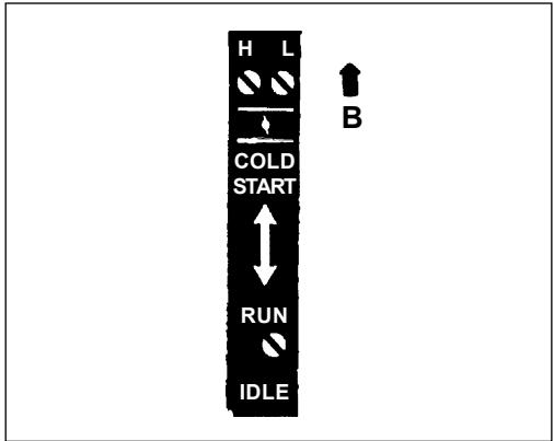
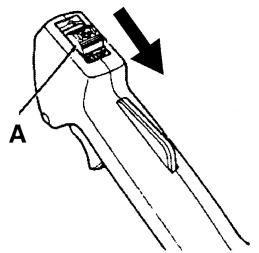
- STOP SWITCH-START/RUN. Move stop switch (A) away from the STOP position.
- CHoke-COLDSTART. Move choke (B) to the Cold Start (CLOSED) position.

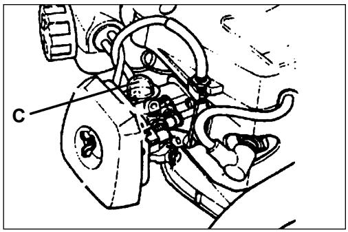
- PRIMER-PUMP BULB. Pump primer bulb (C) until fuel is visible and flows freely in the clear fuel tank return line. Pump bulb an additional 4 or 5 times.
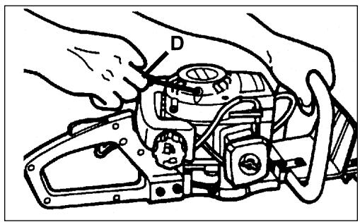
- START-PULL ROPE
Lay the hedge clipper on a flat clear area and pull the recoil starter handle (D) until engine fires.
- OPENCHOKE-RUN.
Move choke (B) to the RUN (OPEN) position. Restart engine if necessary and allow unit to warm up at idle for several minutes.
WARNING

DANGER
The blades should not move at idle. If blades move, readjust carburetor according to "Carburetor Adjustment" instructions in this manual or see your ECHO Dealer, otherwise serious personal injury may result.
- After engine warm up, gradually depress throttle trigger to increase engine RPM to operating speed.

B
STARTING WARM ENGINE
The starting procedure is the same as Cold Start except DO NOT close the choke.
WARNING

DANGER
The blades should not move at idle. If blades move, readjust carburetor according to "Carburetor Adjustment" instructions in this manual or see your ECHO Dealer, otherwise serious personal injury may result.
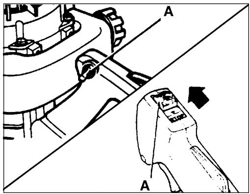
- STOPSWITCH-START/RUN
Move stop switch (A) away from the STOP position.
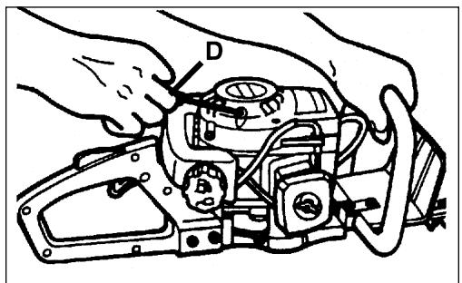
- START-Pull Rope
Lay the hedge clipper on a flat clear area and pull the recoil starter handle (D) until the engine fires.
NOTE
If engine does not start after 5 pulls, use Cold Start Procedure.
STOPPING ENGINE
- RELEASE THROTTLE. Allow engine to idle for a minute.
- STOP SWITCH - STOP. Move stop switch (A) to STOP position.
WARNING

DANGER
If engine does not stop when stop switch is moved to STOP position, close choke - COLD START position - to stall engine. Have your ECHO dealer repair stop switch before using hedge clipper again.
MAINTENANCE
Your ECHO Hedge Clipper is designed to provide many hours of trouble free service. Regular scheduled maintenance will help your Hedge Clipper achieve that goal. If you are unsure or are not equipped with the necessary tools, you may want to take your unit to an ECHO Service Dealer for maintenance. To help you decide whether you want to DO-IT-YOUR-SELF or have the ECHO Dealer do it, each maintenance task has been graded. If the task is not listed, see your ECHO Service Dealer for repairs.
SKILL LEVEL
Level 1 = Easy to do. Most required tools come with unit.
Level2 = Moderate difficulty. Some specialized tools may be required.
Level3= Experience required. Specialized tools are required. ECHO recommends the unit be returned to your ECHO dealer for servicing.
ECHO offers REPOWER™ Maintenance Kits and Parts to make your maintenance job easier. Just below each task heading are listed the various part numbers required for that task. See your ECHO dealer for these parts.
MAINTENANCE INTERVALS
| Component/System | Maintenance Procedure | Before Use | Every Refuel | Daily or Every 4 Hours | 3 Months or 100 Hours | 6 Months or 300 Hours | Yearly or 600 Hours |
| Air Filter | Inspect/Replace | I / C | I / C | R * | |||
| Fuel Strainer | Inspect/Replace | I | R | ||||
| Fuel Line | Inspect/Replace | I | I * | R | |||
| Carburetor | Inspect/Replace | C | R(1) | ||||
| Choke System | Inspect/Replace | I | |||||
| Cooling System | Inspect/Clean | I / C | I / C | ||||
| Muffler Spark Arrestor | Inspect/Clean/Replace | I / C | R | ||||
| Gear Housing | Grease | I (2) | |||||
| Recoil Starter Rope | Inspect/Clean | I | I * | ||||
| Fuel Leaks | Inspect/Repair | I | I | I * | |||
| Spark Plug | Clean | I / C | R * | ||||
| Ignition System | Clean/Replace | No Maintenance required for coil and flywheel | |||||
| Screws/Nuts/Bolts | Inspect/Tighten/Replace | I* | |||||
| I = INSPECT, R = REPLACE, C = CLEANIMPORTANT Time intervals shown are maximum. Actual use and your experience will determine the frequency of required maintenance.* All recommendations to replace are based on the finding of damage or wear during inspection.(1) Replacement will be required for Commercial use after 600 hours. For Consumer use, cleaning every 6 months is required.(2) Apply 1~2 pumps of ECHO® LUBE™ every 10 hours. | |||||||
AIR FILTER
Level 1.
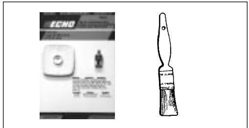
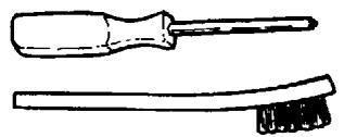
Tools required: 25 or 50mm (1 or 2 in.) medium bristle paint brush
Parts required: 90008 REPOWER™ AIR & FUEL FILTER KIT
- Close choke (Cold Start Position). This prevents dirt from entering the carburetor throat when the air filter is removed. Brush accumulated dirt from the air cleaner area.
- Remove the air cleaner cover. Clean and inspect the element for damage. If element is fuel soaked and very dirty, replace.
- If element can be cleaned and reused, be certain it:
-still fits the cavity in the air cleaner cover.
-is installed with the original side out.
NOTE
Carburetor adjustment may be needed after air filter cleaning/ replacement.
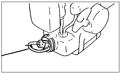
FUEL FILTER
Level 1.
Tools required: 203-254 mm (8-10 in.) length of wire with one end bent into a hook. Clean rag, funnel, and an approved fuel container
Parts required: 90008 REPOWER™ AIR & FUEL FILTER KIT
WARNING

DANGER
Fuel is VERY flammable. Use extreme care when mixing, storing or handling.
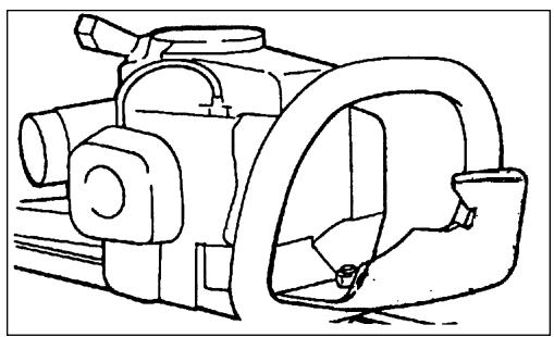
- Use a clean rag to remove loose dirt from around fuel cap and empty fuel tank.
- Use the "fuel line hook" to pull the fuel line and filter from the tank.
- Remove the filter from the line and install the new filter.

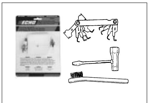
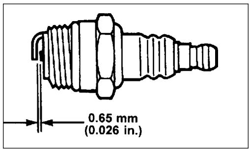
SPARK PLUG
Level 2.
Tools required: T-wrench, Feeler gauge, Soft metal brush
Parts required: 90064 REPOWER™ Tune-UpKit
- Remove spark plug and check for fouling, worn and rounded center electrode.
- Clean the plug or replace with a new one. DO NOT sand blast to clean. Remaining sand will damage engine.
- Adjust spark plug gap by bending outer electrode.
- Tighten spark plug to 145 - 155kg / cm (125-135 in. lb.).
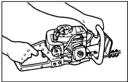
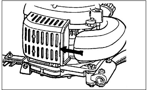
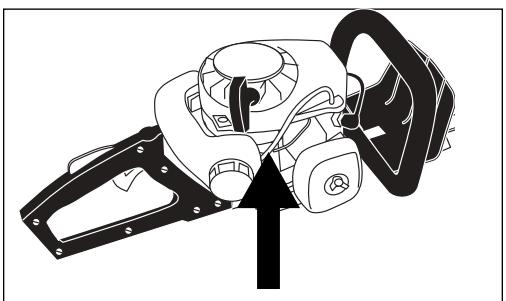
COOLING SYSTEM CLEANING
Level 2.
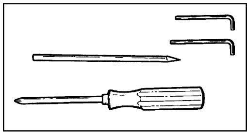
Tools required: 3 mm Allen wrench, 4 mm Allen wrench, Pointed Wood Stick, Cross head Screwdriver
Parts required: None if you are careful.
IMPORTANT
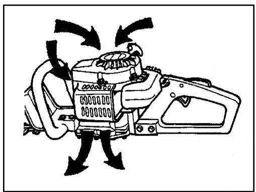
To maintain proper engine operating temperatures, cooling air must pass freely through the cylinder fin area. This flow of air carries combustion heat away from the engine.
Overheating and engine seizure can occur when:
- Air intakes in the crankcase are blocked, preventing cooling air from reaching the cylinder.
- Dust and grass build up on the outside of the cylinder. This build up insulates the engine and prevents the heat from leaving.
Removal of crankcase cooling passage blockages or cleaning of cooling fins is considered "Normal Maintenance". Any failure attributed to lack of maintenance is not warranted.
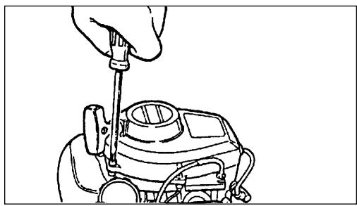
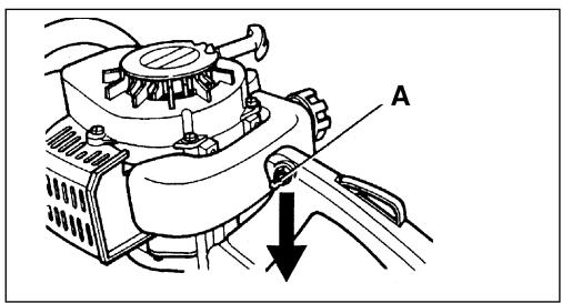
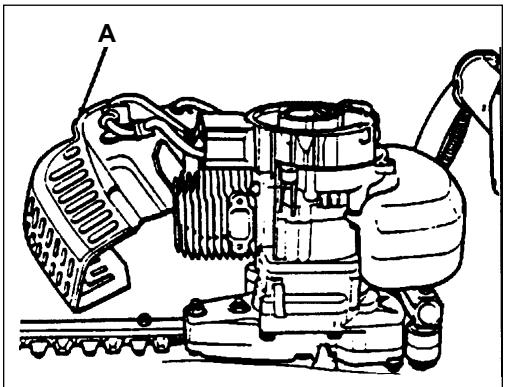
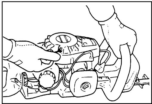
- Remove starter and disconnect the throttle cable end from the carburetor.
- Remove the two screws that retain the engine cover. Lift the engine cover (A) from the engine and lay aside.
NOTE
The throttle cable remains assembled to the engine cover (A) and the spark plug lead and grommet remain installed.
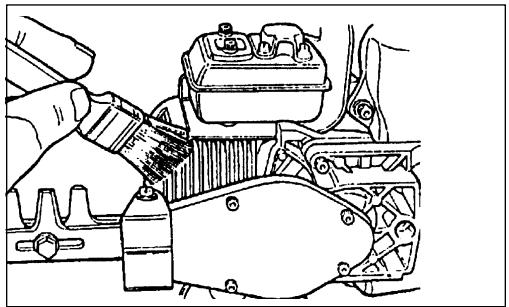
IMPORTANT
DO NOT use a metal scraper to remove dirt from the cylinder fins.
- Use the wooden stick or brush to remove dirt from the cylinder fins.
- Remove grass and leaves from the starter air intake grid.
NOTE
When installing the engine cover (A), be certain the tab of the metal deflector shield is in the slot of the cover.
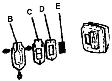
EXHAUST SYSTEM
Spark Arrestor Screen
Level 2.
Tools required: 3mm Allen wrench, Soft metal brush
Parts Required: Screen P/N 14586240630, Gasket Lid P/N 14586642031
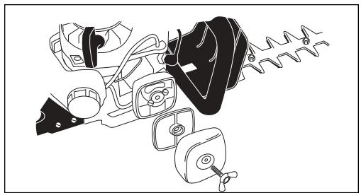
- Remove engine cover (A). See "Cleaning Cooling System" pages 20 & 21 for step by step instructions.
- Place piston at Top Dead Center (TDC) to prevent carbon/dirt from entering cylinder.
- Remove spark arrestor screen cover (B), screen holder (C), gasket (D) and screen (E) from muffler body.
- Clean carbon deposits from screen and muffler components.
- Replace screen if it is cracked, plugged or has holes burned through.
- Assemble components in reverse order.
NOTE
When installing the engine cover, be certain the tab of the metal deflector shield is in the slot of the cover.
CARBURETOR ADJUSTMENT
Emission Models
Level 2.
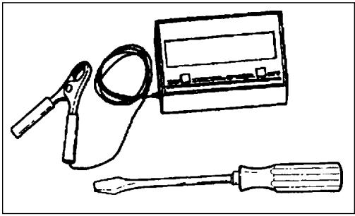
Tools required: Screwdriver with 2mm blade width, Tachometer (ECHOP/N99051130017)
Parts required: None.
NOTE
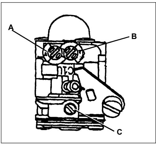
Every unit is run at the factory and the carburetor is set in compliance with EPA Phase 1 and California Emission Regulations. In addition, the carburetor is equipped with HI (A) and LO (B) needle adjustment limiters that prevent settings outside acceptable limits.
- Before adjusting the carburetor, clean or replace the air filter and spark arrester screen.
- Start engine and run for several minutes to reach operating temperature.
- Stop engine. Turn HI (A) speed needle CCW (counter clockwise) to stop. Turn LO (B) speed needle midway between full CCW and CW (clockwise) stops.
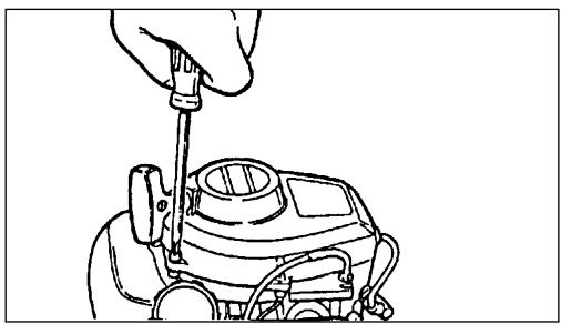
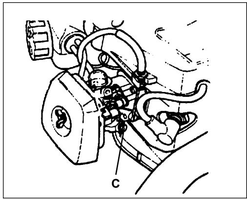
- Idle Speed Adjustment.
- Start engine and turn idle (C) speed adjustment screw CW until the blades begin to move, then turn the screw CCW until blades stop moving. Turn screw CCW an additional 1/4 turn.
- Accelerate to full throttle for 2-3 seconds to clear excess fuel from engine then return to idle. Accelerate to full throttle to check for smooth transition from idle to full throttle. If engine hesitates, turn LO (B) needle CCW an additional 1/8 turn and repeat acceleration. Continue adjusting until smooth acceleration results.
- Check HI speed RPM at W.O.T. (Wide Open Throttle). HI speed RPM should be set to specifications found on page 12 "Specifications" of this manual.
- Check idle speed and reset if necessary. If a tachometer is available, idle speed should be set to the specifications found on page 12 "Specifications" of this manual.
WARNING

DANGER
When carburetor adjustment is completed, blades should not move at idle, otherwise serious personal injury may result.
CARBURETOR ADJUSTMENT
Tools required: Screwdriver with 2mm blade width, Tachometer (ECHO P/N 99051130017)
Parts Required: None
NOTE
If carburetor has limiter caps follow "Carburetor Adjustment" procedures for Emission models on previous page.
Idle Speed Adjustment
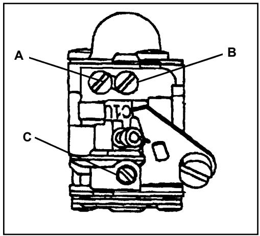
Turn "idle" speed adjustment screw (C) CW (clockwise) until blades begin to move, then turn screw out CCW (counter clockwise) until blades stop moving. Turn screw out, CCW an additional 1/4 turn.
WARNING

DANGER
Blades must not move when unit is idling, otherwise serious personal injury may result.
Basic Setting
- Stop engine and turn both LO (B) and HI (A) needles in, CW until they stop and are lightly seated.
IMPORTANT
DO NOT over tighten needles. Forcing them to tighten will damage the carburetor.
- Turn needles out CCW:
HC-1500 LO (B) 1-1/4 turns; HI (A) 1-1/2 turns
Others (LO) (B) 1-1/4 turns; HI (A) 1-3/8 turns
Fine Tuning
(Requires Accurate Tachometer)
- Start engine and allow to warm to operating temperature (minimum
2 - 3 minutes) while varying engine speed from idle to full throttle.
- Always begin fine tuning with LO (B) needle.
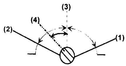
a. Lean drop-off - With engine idling, turn LO (B) needle slowly CW (in) to lean drop-off point. RPM will increase, then abruptly drop-off. Note this position. (1)
b. Rich drop-off - With engine idling, slowly turn LO (B) needle CCW (out) to rich drop-off point. RPM will increase then gradually slow and drop-off. Note this position. (2)
c. Final setting - Set needle at mid point between lean rich drop-off points. (3)
d. Turn needle 1/8 turn CCW (out) making mixture slightly richer. (4)
- HI speed adjustment. Adjust HI (A) needle with tachometer. Refer to Wide Open Throttle RPM settings listed in "Specifications" on page 12.
- Check idle speed and reset if necessary. If tachometer is available, idle speed should be set to the specifications found on page 12 "Specifications" of this manual.
WARNING

DANGER
When carburetor adjustment is completed, blades should not move at idle, otherwise serious personal injury may result.
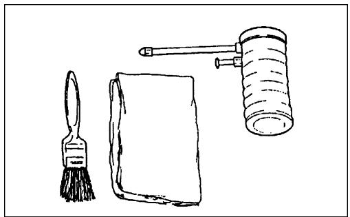
LUBRICATION
Blades
Level 1.
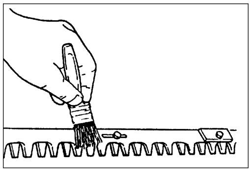
Tools required: Clean rag, 25 or 50mm (1 or 2 in.) medium bristle paint brush
Parts Required: 20W Engine Oil (lubrication), 50-50 mixture of kerosene and 20W oil (cleaning).
WARNING

DANGER
Hedge Clipper Blades are very sharp. Wear gloves to protect hands.
- Disconnect spark plug wire from spark plug.
- Brush loose debris from blade and coat both sides of blade with the 50-50 cleaning mixture.
- Allow cleaning mixture to soften the remaining gummy residue then wipe it from the blade.
- Apply clean oil to the entire length of the blade. Be certain the blade bolts are lubricated.
- Wipe excess oil from the blade before putting the unit back in service.
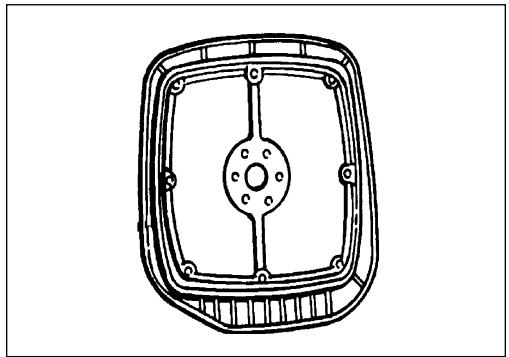
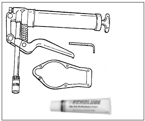
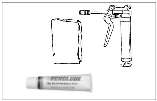
Gear Box Assembly
Level 2.
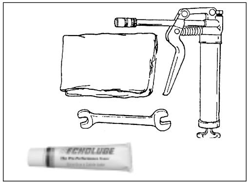
Tools required: 3mm Hexagon wrench, Grease Gun
Parts Required: GearBox Gasket, HC-2400P/N61041401260, HC-15002EP/N61041406560, Others P/N61041405360, ECHO® LUBETM8 oz. (P/N 91014) or Lithium Based Grease.
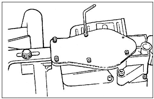
HC-1500 Type 1, Type 1E
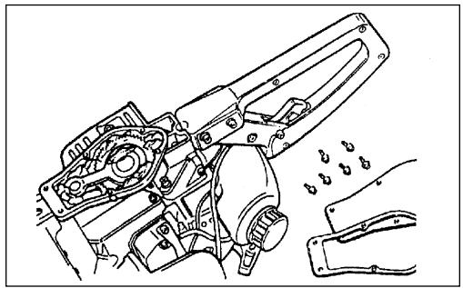
- Clean debris and dirt from gear box area. Remove the six (6) socket head cap screws retaining the gear box cover plate.
- Remove cover plate and discard gasket.
- Add grease as required, DO NOT over fill. Leave room for the grease to expand during operation.
HC-1600, 2000 (All)
Level 1.
Tools required: 13mm Open End, Grease Gun
Parts required: ECHO® LUBETM8 oz. (P/N91014) or Lithium Based Grease.
- Clean dirt from filler plug area and remove plug.
- Carefully pump grease into hole. DO NOT force grease. Too much pressure will force grease past seals and cause damage.
- Wipe excess grease from gear box and replace the filler plug.
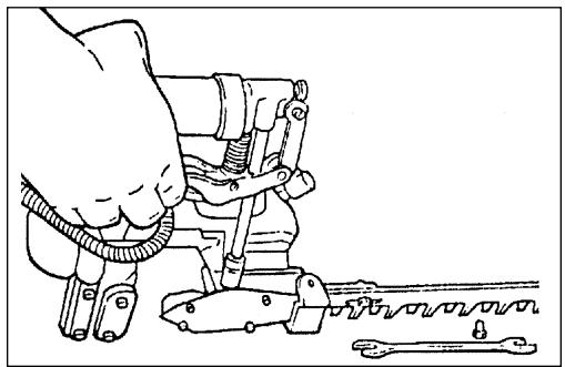
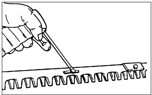
HC-1500, Type 2E, HC-2400, 2410 (All)
Level 1.
Tools required: Grease Gun, Clean rag
Parts required: ECHO® LUBE™8 oz. (P/N91014) or Lithium Based Grease.
- Clean dirt from the grease fitting.
- Carefully pump grease into fitting. DO NOT force grease. Too much pressure will force grease past seals and cause damage.
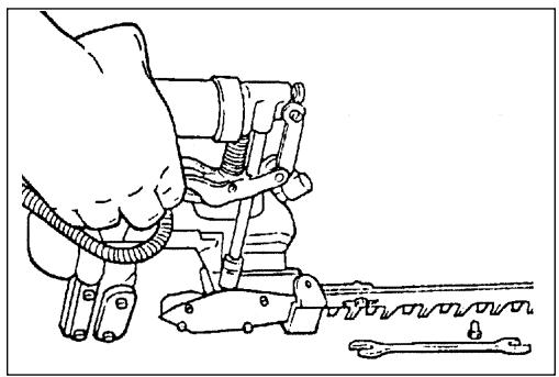
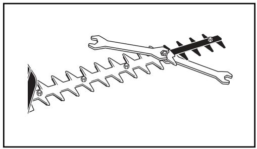
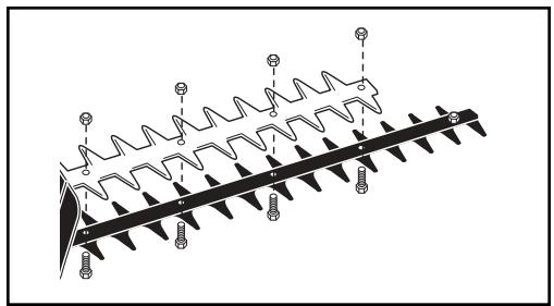
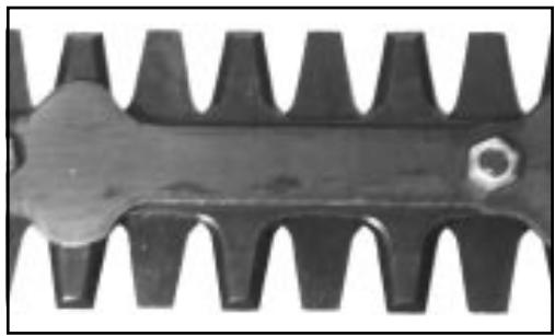
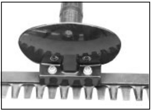
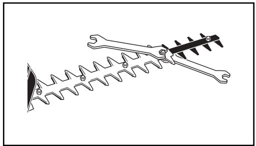
BLADE STIFFENER REMOVE/INSTALL
Level 2.
Tools required: (2) 13mm Open End
Parts Required: None
WARNING

DANGER
Hedge Clipper blades are very sharp. Wear gloves to protect hands.
- Disconnect spark plug wire from spark plug.
- Hold blade bolt head under blade assembly. Remove blade locknut from top side turning counter clockwise.
- Repeat step 2 for remaining blade nuts.
NOTE
Locking ability of Hedge Clipper blade nuts will diminish each time they are removed. Replace blade nuts if threading resistance is not felt when installing locknuts.
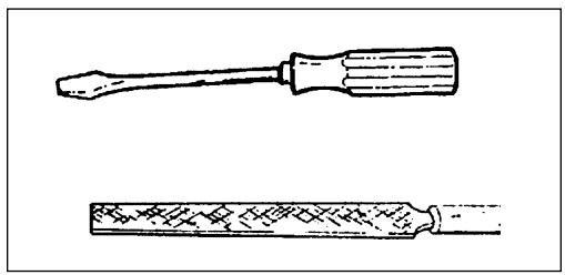
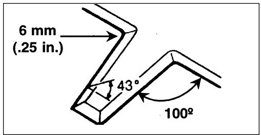
SHARPENING BLADES
Level 3.
Tools required: Flat file, Screwdriver
Parts required: None
WARNING

DANGER
Hedge Clipper Blades are very sharp. Wear gloves to protect hands.
- Disconnect spark plug wire from spark plug.
- (Models HC-1500, HC-1600) Remove blade stiffener (See "Blade Stiffener Remove/Install" on page 26).
- File each edge carefully. Follow the original shape of the blade.
IMPORTANT
If a power grinder is used DO NOT allow blade to over heat.
- (Models HC-1500, HC-1600) Assemble blade stiffener using new blade nuts if required. Tighten bolts and nuts then loosen bolt 1/2 turn to allow free blade movement.
- Lubricate blades. See "Blade Lubrication Instructions," on page 24.
IMPORTANT
Blades should only be removed and reinstalled by an Authorized ECHO Servicing Dealer, otherwise premature wear or internal damage may occur.
TROUBLESHOOTING
| Problem | Cause | Remedy | |||
| Engine -- starts hard Engine -- does not start | |||||
| Engine Cranks | Fuel at carburetor | No fuel at carburetor | Fuel strainer clogged Fuel line clogged Carburetor | Clean Clean See your ECHO dealer | |
| Fuel at cylinder | No fuel at cylinder | Carburetor | See your ECHO dealer | ||
| Muffler wet with fuel | Fuel Mixture is too rich | Open choke Clean/replace air filter Adjust carburetor See your ECHO dealer | |||
| Spark at end of plug wire | No spark at end of plug wire | Stop switch off Electrical problem Interlock switch | Turn switch on See your ECHO dealer See your ECHO dealer | ||
| Spark at plug | No spark at plug | Spark gap incorrect Covered with carbon Fouled with fuel Spark plug defective | Adjust 0.65mm (0.026in.) Clean or replace Clean or replace Replace plug | ||
| Engine does not crank | Internal engine problem | See your ECHO dealer | |||
| Engine runs | Dies or accelerates poorly | Air filter dirty Fuel filter dirty Fuel vent plugged Spark plug Carburetor Cooling system plugged Spark arrestor screen plugged | Clean or replace Replace Replace Clean and adjust/replace Adjust Clean Clean | ||
WARNING

DANGER
Fuel vapors are extremely flammable and may cause fire and/or explosion. Never test for ignition spark by grounding spark plug against cylinder, otherwise serious personal injury may result.
STORAGE
Long Term Storage (over 30 days)
Do not store your unit for a prolonged period of time (30 days or longer) without performing protective storage maintenance which includes the following:
- Store unit in a dry, dust free place, out of the reach of children.
WARNING

DANGER
Do not store in enclosure where fuel fumes may accumulate or reach an open flame or spark.
- Place the stop switch (A) in the "OFF" position.
- Remove accumulation of grease, oil, dirt and debris from exterior of unit.
- Perform all periodic lubrication and services that are required.
- Tighten all the screws and nuts.
- Drain the fuel tank completely and pull the recoil starter handle several times to remove fuel from the carburetor.
- Remove the spark plug and pour 1/4 oz. (1/2 tablespoon) of fresh, clean, two-stroke engine oil into the cylinder through the spark plug hole.
A. Place a clean cloth over the spark plug hole.
B. Pull the recoil starter handle 2-3 times to distribute the oil inside the engine.
C. Observe the piston location through the spark plug hole. Pull the recoil handle slowly until the piston reaches the top of its travel and leave it there.
- Install the spark plug (do not connect ignition cable).
NOTES
SERVICING INFORMATION
PARTS
Genuine ECHO Parts and ECHO REPOWER™ Parts and Assemblies for your ECHO products are available only from an Authorized ECHO Dealer. When you do need to buy parts always have the Model Number and Serial Number of the unit with you. You can find these numbers on the engine housing. For future reference, write them in the space provided below.
Model No. SN.
SERVICE
Service of this product during the warranty period must be performed by an Authorized ECHO Service Dealer. For the name and address of the Authorized ECHO Service Dealer nearest you, ask your retailer or call: 1-800-432-ECHO (3246). Dealer information is also available on our Web Site. When presenting your unit for Warranty service/repairs, proof of purchase is required.
ECHO CONSUMER PRODUCT SUPPORT
If you require assistance or have questions concerning the application, operation or maintenance of this product you may call the ECHO Consumer Product Support Department at 1-800-673-1558 from 8:30 am to 4:30 pm (Central Standard Time) Monday through Friday. Before calling, please know the model and serial number of your unit to help your Consumer Product Support Representative.
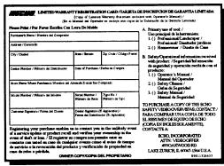
WARRANTY REGISTRATION
You may register your Echo equipment using the warranty registration card or register on-line at www. echo-usa.com. Registering provides a direct link between you and ECHO if we find it necessary to contact you.
DEALER?
Call
1-800-432-ECHO
1-800-432-3246
www. echo -usa.com
CONSUMER PRODUCT SUPPORT
1-800-673-1558
8:30 - 4:30 Mon - Fri C.S.T.

ADDITIONAL OR REPLACEMENT MANUALS
Safety Manuals in English/Spanish or English/French are available, free of charge, from your ECHO dealer or at www.echo-usa.com.
Operator's and Parts Manuals are available by:
- Downloading free from www. echo-usa.com
- Purchasing from your Echo Dealer.
- Sending a check or money order for 2.00 per Parts Catalog or 1.50 per Operator's Manual made payable to ECHO, INCORPORATED. State on a sheet of paper the model number and serial number of the ECHO unit you have, part number of the manual (if known), your name and address and mail to address above.
Safety Videos are available from your Echo dealer. A $5.00 shipping charge will be required for each video.
Available Parts Catalog Parts Lists
HC-1500Type1E
SerialNumber001001UP
P/N99922202758
HC-1500 Type2E
Serial Number001001 UP
P/N99922202898
HC-1600 Type 1E
SerialNumber001001UP
P/N99922202759
HC-2000Type1E
SerialNumber001001UP
P/N99922202760
HC-2400/2410 Type 1E
Serial Number 001001 UP
P/N99922202761
HC-2400/2410 Type 2E
Serial Number001001 UP
P/N99922202762

ECHO, INCORPORATED
400 OAKWOOD ROAD
LAKE ZURICH, IL 60047-1564
www. echo -usa.com