RD-5503 - Audio Amplifier SHERWOOD - Free user manual and instructions
Find the device manual for free RD-5503 SHERWOOD in PDF.
User questions about RD-5503 SHERWOOD
0 question about this device. Answer the ones you know or ask your own.
Ask a new question about this device
Download the instructions for your Audio Amplifier in PDF format for free! Find your manual RD-5503 - SHERWOOD and take your electronic device back in hand. On this page are published all the documents necessary for the use of your device. RD-5503 by SHERWOOD.
USER MANUAL RD-5503 SHERWOOD
This symbol is intended to alert the user to the presence of uninsulated "dangerous voltage" within the product's enclosure that may be of sufficient magnitude to constitute a risk of electric shock to persons.

This symbol is intended to alert the user to the presence of important operating and maintenance (servicing) instructions in the literature accompanying the appliance.
WARNING : TO REDUCE THE RISK OF FIRE OR ELECTRIC SHOCK, DO NOT EXPOSE THIS APPLIANCE TO RAIN OR MOISTURE.
Caution regarding installation
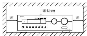
Note : For heat dispersal, do not install this unit in a confined space such as a bookcase or similar enclosure.
Do not block ventilation openings or stack other equipment on the top.
text_image
※ Note ※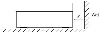
natural_image
Simple line drawing of a rectangular tank with a wall and a dimension mark (no text or symbols)FOR YOUR SAFETY
| EUROPE AUSTRALIA | 220 V - 240 V | Units shipped to Australia are designed for operation on 230 V AC only.To ensure safe operation, the three-pin plug supplied must be inserted only into a standard three-pin power point which is effectively earthed through the normal household wiring. Extension cords used with the equipment must be three-core and be correctly wired to provide connection to earth.Improper extension cords are a major cause of fatalities. The fact that the equipment operates satisfactorily does not imply that the power point is earthed and that the installation is completely safe. For your safety, if in any doubt about the effective earthing of the power point, consult a qualified electrician.PAN-EUROPEAN UNIFIED VOLTAGEAll units are suitable for use on supplies 220-240 V AC. |
CAUTION
- Leave a space around the unit for sufficient ventilation.
- Avoid installation in extremely hot or cold locations, or in an area that is exposed to direct sunlight or heating equipment.
- Keep the unit free from moisture, water, and dust.
- Do not let foreign objects in the unit.
- The ventilation should not be impeded by covering the ventilation openings with items, such as newspapers, table-cloths, curtains, etc.
- No naked flame sources, such as lighted candles, should be placed on the unit.
- Please be care the environmental aspects of battery disposal.
- The unit shall not be exposed to dripping or splashing for use.
- No objects filled with liquids, such as vases, shall be placed on the unit.
- Do not let insecticides, benzene, and thinner come in contact with the set.
- Never disassemble or modify the unit in any way.
■ Notes on the AC power cord and the wall outlet. - The unit is not disconnected from the AC power source(mains) as long as it is connected to the wall outlet, even if the unit has been turned off.
- To completely disconnect this product from the mains, disconnect the plug from the wall socket outlet.
- When setting up this product, make sure that the AC outlet you are using is easily acceptable.
- Disconnect the plug from the wall outlet when not using the unit for long periods of time.
Note on recycling
This product's packaging materials are recyclable and can be reused. Please dispose of any materials in accordance with the local recycling regulations.
When discarding the unit, comply with local rules or regulations.
Batteries should never be thrown away or incinerated but disposed of in accordance with the local regulations concerning chemical waste.
This product and the accessories packed together constitute the applicable product according to the WEEE directive except batteries.


CONTENTS
Introduction
- READ THIS BEFORE OPERATING YOUR UNIT .... 2
System Connections 4
Front Panel Controls 8
Remote Controls 9
( RDS Tuner (Regional Option for some countries in Europe, etc))
- RECORDING 24
- OTHER FUNCTIONS 25
• USING DIFFERENT FUNCTIONS ON THE FRONT PANEL 26
System Setup 27
- SETTING THE SYSTEM 29
- SETTING THE INPUT 31
- SETTING THE SPEAKER SETUP 32
- SETTING THE CH LEVEL 36
- SETTING THE PARAMETER 38
Troubleshooting Guide 40
Specifications 41
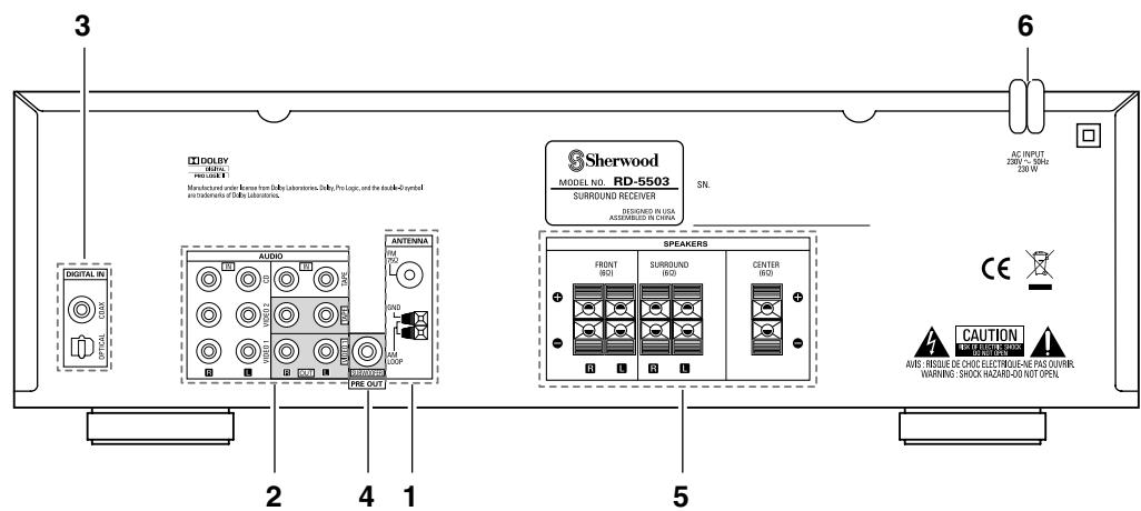
System Connections
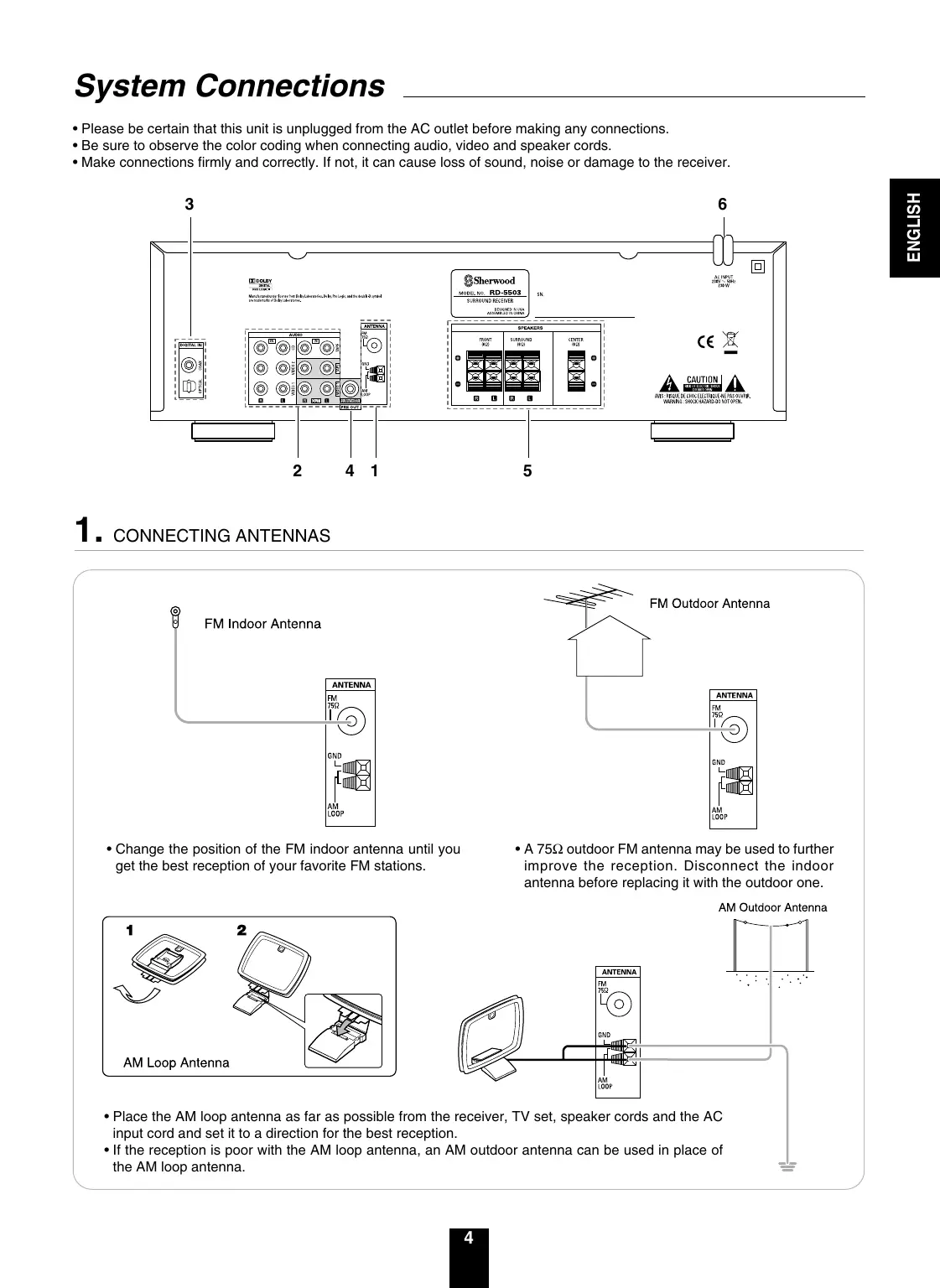
- Please be certain that this unit is unplugged from the AC outlet before making any connections.
- Be sure to observe the color coding when connecting audio, video and speaker cords.
- Make connections firmly and correctly. If not, it can cause loss of sound, noise or damage to the receiver.
text_image
3 DIGITAL IN OPTICAL DIGALY MILK Manufactured under license from Dolby Laboratories, Dolby Pro Logic, and the double-2 symbol and trademarks of Dolby Laboratories. AUDIO AM ON SUN OFF COOP FREE OUT 4 1 2 5 6 AC INPUT 200V - 50Hz 230 W SHERWOOD MODEL NO. RD-5503 SURROUND RECEIVER RESCARD IN USA ASSEMBLED IN CHINA SN. FRONT ISO1 SURROUND ISO2 CENTER ISO3 CAUTION LED & AIR & FLOW AVS: INSULIE DE CHOC ELECTRIQUE-IN PAS OUVER. WARNING: SHOCK-HAZARD-DO NOT OPEN.1. CONNECTING ANTENNAS
text_image
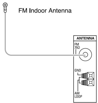
FM Indoor Antenna ANTENNA FM 75Ω GND AM LOOP- Change the position of the FM indoor antenna until you get the best reception of your favorite FM stations.
text_image
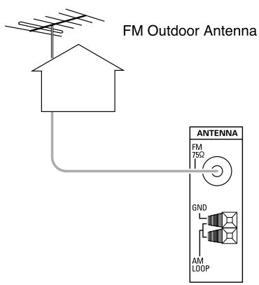
FM Outdoor Antenna ANTENNA FM 75Ω GND AM LOOP- A 75Ω outdoor FM antenna may be used to further improve the reception. Disconnect the indoor antenna before replacing it with the outdoor one.
text_image
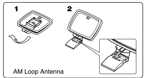
1 2 AM Loop Antenna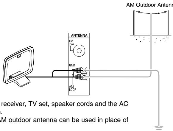
text_image
AM Outdoor Antenn ANTENNA FM 75Ω GND AM LOOP receiver, TV set, speaker cords and the AC . AM outdoor antenna can be used in place of- Place the AM loop antenna as far as possible from the receiver, TV set, speaker cords and the AC input cord and set it to a direction for the best reception.
- If the reception is poor with the AM loop antenna, an AM outdoor antenna can be used in place of the AM loop antenna.
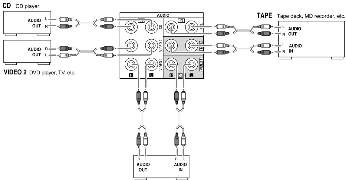
2. CONNECTING AUDIO/VIDEO COMPONENTS
- The VIDEO 1/VIDEO 2 jacks may be connected to AUDIO jacks of video components such as DVD player, TV, etc..
- The TAPE IN/OUT jacks and the VIDEO 1 IN/OUT jacks can be connected to audio recording equipment such as a tape deck, an MD recorder, etc..
flowchart
graph TD
    A["CD CD player"] --> B["AUDIO OUT"]
    A --> C["AUDIO OUT"]
    D["VIDEO 2 DVD player, TV, etc."] --> E["TAPE Tape deck, MD recorder, etc."]
    E --> F["TAPE TAPE"]
    B --> G["VIDEO 1"]
    C --> H["VIDEO 2"]
    E --> I["TAPE TAPE"]
    G --> J["TAPE TAPE"]
    H --> K["TAPE TAPE"]
    I --> L["TAPE TAPE"]
    J --> M["TAPE TAPE"]
    K --> N["TAPE TAPE"]
    L --> O["TAPE TAPE"]
    M --> P["TAPE TAPE"]
    N --> Q["TAPE TAPE"]
    O --> R["TAPE TAPE"]
    P --> S["TAPE TAPE"]
VIDEO 1 DVD player, tape deck, MD recorder, etc.
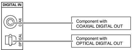
3. CONNECTING DIGITAL INs
- The OPTICAL and the COAXIAL DIGITAL OUTs of the components that are connected to CD and VIDEO 1 of this unit can be connected to these DIGITAL INs.
- A digital input should be connected to the components such as a CD player, LD player, DVD player, etc. capable of outputting Dolby Digital or PCM format digital signals, etc.
- For details, refer to the operating instructions of the component connected.
- When making the COAXIAL DIGITAL connection, be sure to use a 75 COAXIAL cord, not a conventional AUDIO cord.
- All of the commercially available optical fiber cords cannot be used for the equipment. If there is an optical fiber cord which cannot be connected to your equipment, consult your dealer or nearest service organization.
flowchart
graph LR
    A["Digital IN"] --> B["AX"]
    A --> C["C"]
    A --> D["OP"]
    B --> E["Component with COAXIAL DIGITAL OUT"]
    C --> F["Component with OPTICAL DIGITAL OUT"]
■Note : Be sure to make either a OPTICAL or a COAXIAL DIGITAL connection on each component. (You don't need to do both.)
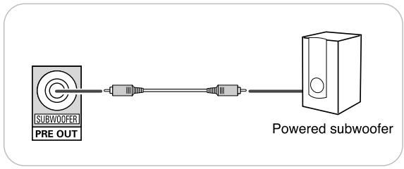
4. CONNECTING SUBWOOFER PRE OUT
- To emphasize the deep bass sounds, connect a powered subwoofer.
flowchart
graph LR
    A["SUBWOOFER PRE OUT"] --> B["Component 1"]
    A --> C["Component 2"]
    C --> D["Powered subwoofer"]
5. CONNECTING SPEAKERS
- Be sure to connect speakers firmly and correctly according to the channel(left and right) and the polarity(+ and -). If the connections are faulty, no sound will be heard from the speakers, and if the polarity of the speaker connection is incorrect, the sound will be unnatural and lack bass.
- For installing the speakers, refer to "Speaker placement" on page 7.
- After installing the speakers, first adjust the speaker settings according to your environment and speaker layout. (For details, refer to "SETTING THE SPEAKER SETUP" on page 32.)
Caution :
- Be sure to use the speakers with the impedance of 6 ohms or above.
- Do not let the bare speaker wires touch each other or any metal part of this unit. This could damage this unit and/or the speakers.
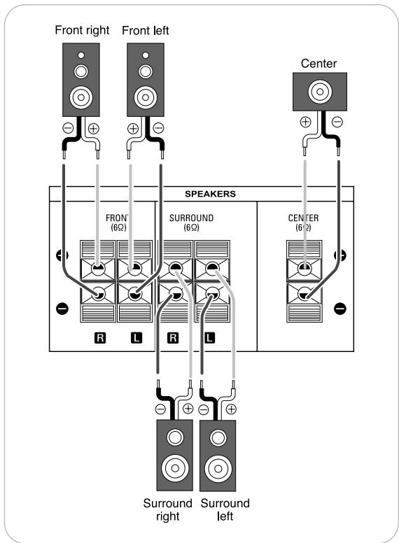
text_image
Front right Front left Center FRONT SPEAKERS SURROUND CENTER R L R L Surround right Surround left6. AC INPUT CORD
- Plug the cord into a wall AC outlet.
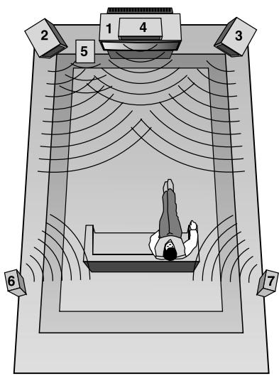
Speaker placement
Ideal speaker placement varies depending on the size of your room and the wall coverings, etc. The typical example of speaker placement and recommendations are as follows :
■ Front left and right speakers and center speaker
- Place the front speakers with their front surfaces as flush with TV or monitor screen as possible.
- Place the center speaker between the front left and right speakers and no further from the listening position than the front speakers.
- Place each speaker so that sound is aimed at the location of the listener's ears when at the main listening position.
■ Surround left and right speakers
- Place the surround speakers approximately 1 meter (40 inches) above the ear level of a seated listener on the direct left and right of them or slightly behind.
Subwoofer
- The subwoofer reproduces powerful deep bass sounds. Place a subwoofer anywhere in the front as desired.
Notes :
- When using a conventional TV, to avoid interference with the TV picture, use only magnetically shielded front left and right and center speakers.
- To obtain the best surround effects, the speakers except the subwoofer should be full range speakers.
text_image
1 2 3 4 5 6 7- TV or screen
- Front left speaker
- Front right speaker
- Center speaker
- Subwoofer
- Surround left speaker
- Surround right speaker
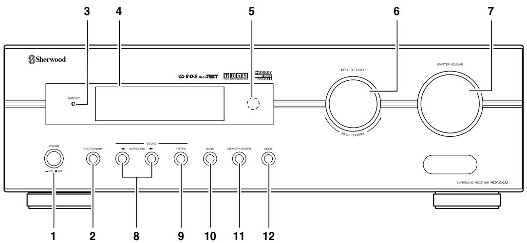
text_image
Sherwood 3 4 5 6 7 RDS Audio Text IDAS STANDBY POWER ON/STANDBY SURROUND STUDIO BAND MEMORY/ENTER MODE ON OFF 1 2 8 9 10 11 12 INPUT SELECTOR MAKS CONTROLS MASTER VOLUME SURROUND REGISTER RD-550G- POWER switch
- POWER ON/STANDBY button
- STANDBY indicator
- FLUORESCENT DISPLAY For details, see below.
- REMOTE SENSOR
-
INPUT SELECTOR/MULTI CONTROL knob
-
MASTER VOLUME CONTROL knob
- SURROUND MODE UP/DOWN (▶ / ◀) buttons
- STEREO button
- BAND button
- MEMORY/ENTER button
- MODE button
■FLUORESCENT DISPLAY
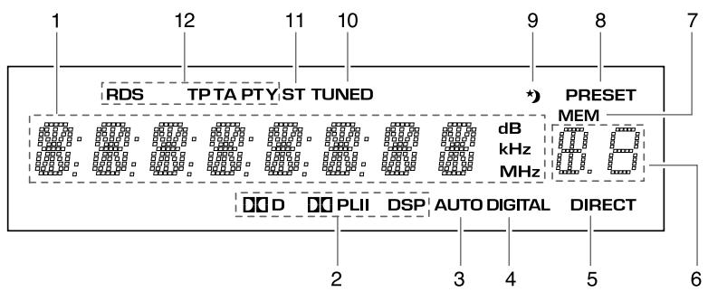
text_image
RDS TPTA PTY ST TUNED PRESET MEM dB kHz MHz D PLII DSP AUTO DIGITAL DIRECT 1 12 11 10 9 8 7 2 3 4 5 6- Input, frequency, volume level, operating information, etc.
- Surround mode indicators
- AUTO indicator
- DIGITAL INPUT indicator
- DIRECT indicator
-
Preset number, sleep time display
-
MEMORY indicator
- PRESET indicator
- SLEEP indicator
- TUNED indicator
- STEREO indicator
- RDS indicators
(Regional option for Europe, etc.)
text_image
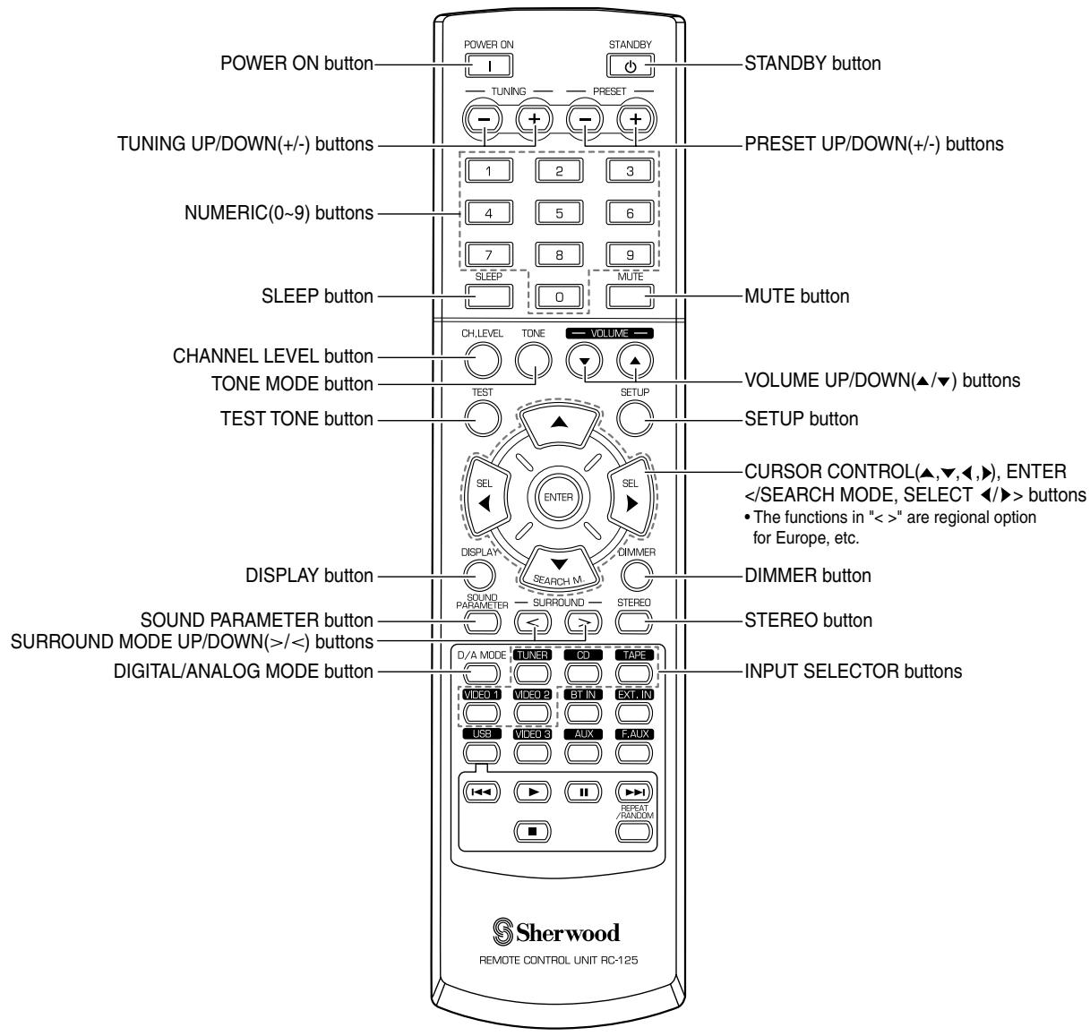
POWER ON button TUNING UP/DOWN(+/-) buttons NUMERIC(0~9) buttons SLEEP button CHANNEL LEVEL button TONE MODE button TEST TONE button DISPLAY button SOUND PARAMETER button SURROUND MODE UP/DOWN(>|/<) buttons DIGITAL/ANALOG MODE button POWER ON STANDBY TUNING PRESET 1 2 3 4 5 6 7 8 9 SLEEP MUTE 0 CH,LEVEL TONE VOLUME VOLUME UP/DOWN(▲/▼) buttons TEST SETUP SELECT ENTER SEL SEMICONER DISPLAY SURROUND STEREO D/A MODE TUNER CD TAPE VIDEO 1 VIDEO 2 STIN EXT IN USB VIDEO 3 AUX LAUX RESET/RANDOM MUTE button CURSOR CONTROL(▲,▼,◀,▶), ENTER buttons • The functions in "<>" are regional option for Europe, etc. DIMMER button STEREO button INPUT SELECTOR buttons Sherwood REMOTE CONTROL UNIT RC-125■Note: Some input selector buttons(BT IN, EXT. IN, USB, VIDEO 3, AUX, F.AUX) and USB transport buttons(I◄◄, ►, II, ►►, ■, REPEAT/RANDOM) are not available for this unit.
text_image
Sterwood 7m 30° 30° • Use the r feet) and- Use the remote control unit within a range of about 7 meters (23 feet) and angles of up to 30 degrees aiming at the remote sensor.
LOADING BATTERIES
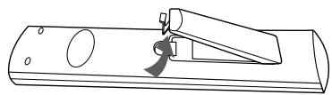
1. Remove the cover.
natural_image
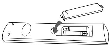
Line drawing of a mechanical device with a lever and circular components (no text or symbols)2. Load two batteries ("AAA" size, 1.5 V) matching the polarity.
natural_image
Diagram of a remote control with two batteries and a battery inside (no text or symbols)- Remove the batteries when they are not used for a long time.
- Do not use the rechargeable batteries (Ni-Cd type).
■ Note : Before operating this receiver, first set this unit as desired for optimum performance, doing the system setup procedures. (For details, refer to "System Setup" on page 27.)
LISTENING TO A PROGRAM SOURCE
Before operation
- Enter the standby mode.
- The STANDBY indicator lights up. This means that the receiver is not disconnected from the AC mains and a small amount of current is retained to support the operation readiness.
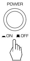
- To switch the power off, push the POWER switch again.
- Then the power is cut off and the STANDBY indicator goes off.
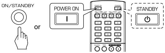
1. In the standby mode, turn the power on.
text_image
ON/STANDBY or POWER ON I STANDBY- Each time the POWER ON/STANDBY button on the front panel is pressed, the receiver is turned on to enter the operating mode or off to enter the standby mode.
- On the remote control, press the POWER ON button to enter the operating mode or press the STANDBY button to enter the standby mode.
- In the standby mode, if the INPUT SELECTOR button is pressed or the INPUT SELECTOR/MULTI CONTROL knob is rotated, the receiver is turned on automatically and the desired input is selected.
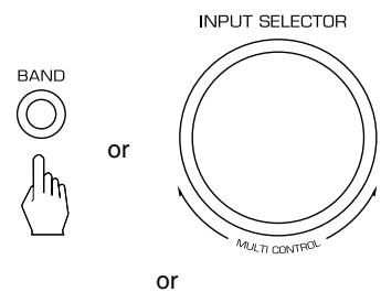
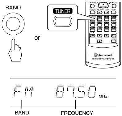
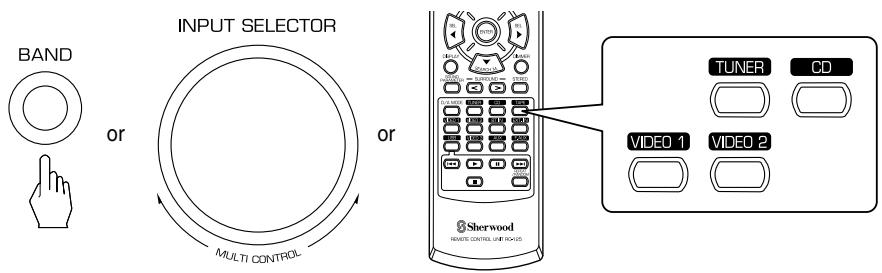
2. Select the desired input source.
text_image
BAND or INPUT SELECTOR MULTI CONTROL or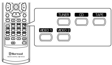
text_image
TUNER CD TAPE VIDEO 1 VIDEO 2 Sherwood REMOTE CONTROL UNIT NO.035• Each time the INPUT SELECTOR/MULTI CONTROL knob is rotated, the input source changes as follows:
→ TUNER ↔ CD ↔ TAPE ↔ VIDEO 1 ↔ VIDEO 2 ←
(Frequency display)
• Each time the BAND button on the front panel or the TUNER button on the remote control is pressed, the band changes as follows:
→ FM ST → FM MONO → AM
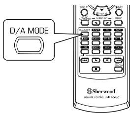
When CD, VIDEO 1 is selected as an input source
3. Select the digital or the analog input connected as desired.
text_image
D/A MODE Sherwood REMOTE CONTROL LIME 100-125• Each time this button is pressed, the corresponding input is selected as follows:
$$ \boxed {\rightarrow \mathrm{o(ptical)} \rightarrow \mathrm{c(oaxial)} \rightarrow \mathrm{A(nalog)}} $$
Notes :
- When TUNER, TAPE or VIDEO 2 is selected as an input source, the digital input cannot be selected.
- When the selected digital input is not connected, the "DIGITAL" indicator flickers and the analog input is automatically selected.
- The selected digital or analog input is automatically assigned to the corresponding input source on the INPUT setup menu. (For details, refer to "SETTING THE INPUT" on page 31.)
- The sound from the component connected to the selected digital input can be heard regardless of the selected input source.
4. Operate the selected component for playback.
- When playing back the program sources with surround sound, refer to “ENJOYING SURROUND SOUND” on page 15.
5. Adjust the (overall) volume.
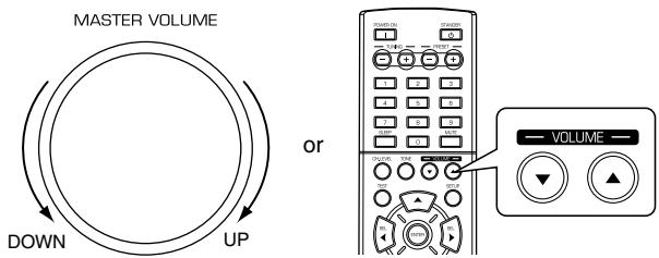
text_image
MASTER VOLUME DOWN UP or VOLUME6. To mute the sound.
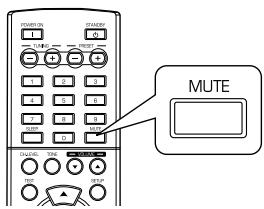
text_image
MUTE- "MUTE" will flicker.
- To resume the previous sound level, press it again.
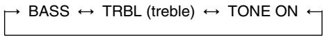
7. Enter the tone mode.
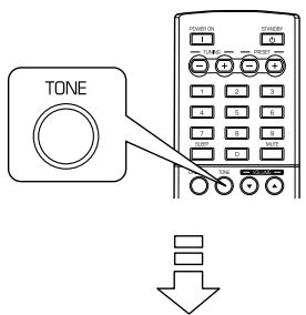
text_image
TONE POMS ON 1 2 3 4 5 6 7 8 9 10 11 12 13 14 15 16 17 18 19 20 21 22 23 24 25 26 27 28 29 30 31 32 33 34 35 36 37 38 39 40 41 42 43 44 45 46 47 48 49 50 51 52 53 54 55 56 57 58 59 60 61 62 63 64 65 66 67 68 69 70 71 72 73 74 75 76 77 78 79 80TONE: OFF
- The tone mode is displayed for several seconds.
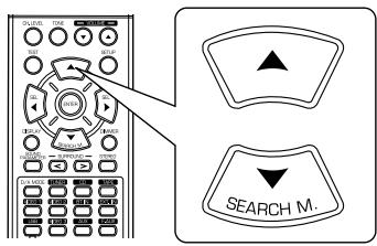
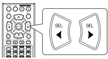
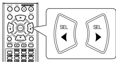
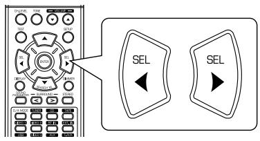
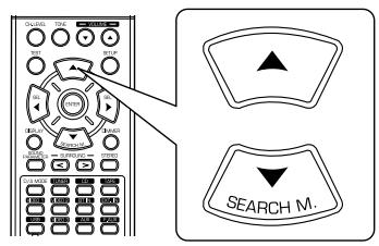
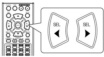
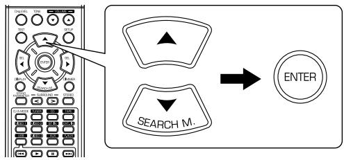
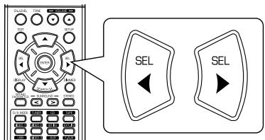
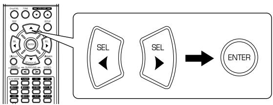
8. Press the CURSOR LEFT(◀)/RIGHT(▶) buttons to select the desired tone mode.

text_image
Diagram showing a remote control with labeled buttons and two 'SEL' button options• Each time these buttons are pressed, the tone mode is selected as follows :
OFF : To listen to a program source without the tone effect.
("DIRECT" indicator lights up.)
ON : To adjust the tone for your taste.
("DIRECT" indicator goes off.)
■ When the TONE is set to ON to adjust the tone (bass and treble).
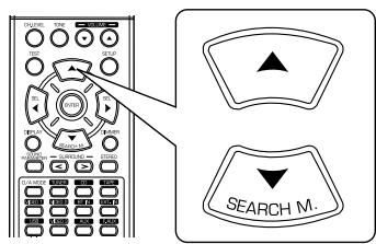
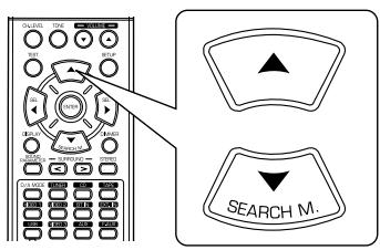
9. Press the CURSOR UP(▲)/DOWN(▼) buttons to select the desired tone.
text_image
OUTPUT TIME ON ON ON ON ON ON ON ON ON ON ON ON ON ON ON ON ON ON ON ON ON ON ON ON ON ON ON ON ON ON ON ON ON ON ON ON ON ON ON ON ON ON ON ON ON ON ON ON ON ON ONE ON ONE ON ONE ON ONE ON ONE ON ONE ON ONE ON ONE ON ONE ON ONE ON ONE ON ONE ON ONE ON ONE ON ONE ON ONE ON ONE ON ONE ON ONE ON ONE ON ONE ON ONE ON ONE ON ONE ON ONE ON ONE ON ONE ON ONE ON ONE ON ONE ON ONE ON ONE ON ONE ON ONE ON• Each time these buttons are pressed, the tone is selected as follows :
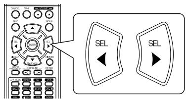
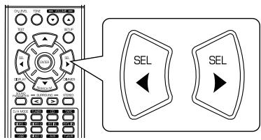
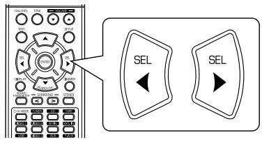
10. Press the CURSOR LEFT(◀)/RIGHT(▶) buttons to adjust the selected tone as desired.

text_image
Diagram showing a remote control interface with two labeled 'SEL' buttons, one pointing to the left panel and the other to the right panel.- The tone level can be adjusted within the range of -10 \~ +10 dB.
- In general, we recommend the bass and treble to be adjusted to 0 dB (flat level).
- Extreme settings at high volume may damage your speakers.
- To complete tone adjustment, repeat the above steps 9 and 10.
- If the tone display disappears, start from the step 7 again.
SURROUND SOUND
- This receiver incorporates a sophisticated Digital Signal Processor that allows you to create optimum sound quality and sound atmosphere in your personal Home Theater.
Surround modes
■ Dolby Digital
Dolby Digital is the multi-channel digital signal format developed by Dolby Laboratories. Discs bearing the Dolby Digital logo includes the recording of up to 5.1 channels of digital signals, which can reproduce much better sound quality, spatial expansion and dynamic range characteristics than the previous Dolby Surround effect.
■ Dolby Pro Logic II surround
This mode applies conventional 2-channel signals such as digital PCM or analog stereo signals as well as Dolby Surround signals, etc. to surround processing to offer improvements over conventional Dolby Pro Logic circuits. Dolby Pro Logic II surround includes 2 modes as follows:
• Dolby Pro Logic II MOVIE
When enjoying movies, this mode allows you to further enhance the cinematic quality by adding processing that emphasizes the sounds of the action special effects.
• Dolby Pro Logic II MUSIC
When listening to music, this mode allows you to further enhance the sound quality by adding processing that emphasizes the musical effects.
■ Dolby Pro Logic
This mode expands any 2-channel sources(, including Dolby Surround sources) for 4 channel(front left, center, front right and surround) play back. The surround channel is monaural, but is played through two surround speakers.
Dolby, Pro Logic, and the double-D symbol are registered trademarks of Dolby Laboratories.
- The following modes apply conventional 2-channel signals such as digital PCM or analog stereo signals to high performance Digital Signal Processor to recreate sound fields artificially.
■ MATRIX
This mode reproduces a delayed signals from the surround channels to emphasize the sense of expansion for music sources.
■CHURCH
This mode provides the ambience of a church for baroque, string orchestral or choral group music.
THEATER
This mode provides the effect of being in a movie theater when watching a movie source.
HALL
This mode provides the ambience of a concert hall for classical music sources such as orchestral, chamber music, or an instrumental solo.
■STADIUM
This mode provides the expansive sound field to achieve the true stadium effect when watching baseball or soccer games.
- Before surround playback, first perform the speaker setup procedure, etc. on the SETUP menu for optimum performance. (For details, refer to "SETTING THE SPEAKER SETUP" on page 32.)
- Even when the auto surround mode is selected and the same type of digital signal format is being input, the optimum surround mode may vary depending on whether the speaker type is set to "N (None)" or not.
- When 96 kHz PCM digital signal is being input, only the stereo mode will be selected.
■ Select the desired surround mode
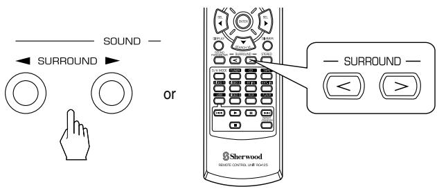
- Each time the SURROUND MODE UP/DOWN (▶, >/◀, <) buttons are pressed, the surround mode changes as follows: Manual surround mode: You can select the desired of (“AUTO” indicator goes off.) different surround modes selectable for the signal being input. Auto surround mode: The optimum surround mode will (“AUTO” indicator lights off.) be automatically selected depending on the signal format being input.
| Signal format being input | Selectable surround mode |
| Dolby Digital 5.1 channel sources | [DOLBY DIGITAL, AUTO SURROUND] or |
| Dolby Digital 2 channel sources | [DOLBY PLII MOVIE, DOLBY PLII MUSIC, DOLBY PRO LOGIC, AUTO SURROUND] or |
| PCM (2channel) sources, Analog stereo sources | [DOLBY PLII MOVIE, DOLBY PLII MUSIC, DOLBY PRO LOGIC, MATRIX, CHURCH, THEATER, HALL, STADIUM, AUTO SURROUND] or |
- Depending on speaker setting, some surround modes can be selected or not as follows :
[ ] : Possible only when "CENTER" or/and "SURR (Surround)" is/are not set to "N (None)".
<> : Possible only when "CENTER" and "SURR (Surround)" are set to "N (None)".
■ To cancel the surround mode for stereo operation
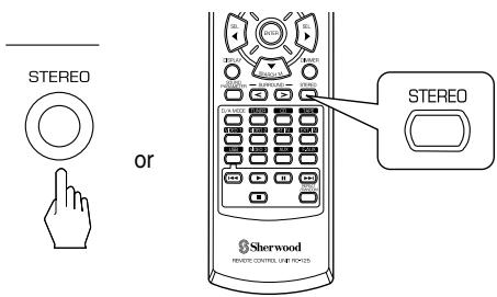
text_image
STEREO or STEREO Sherwood REWEYE CONTROL LIGHT NO.125- Depending on the signal format which is being input, either the stereo mode or the 2CH downmix mode is selected.
- To cancel either the stereo mode or the 2CH downmix mode, select the surround mode with using the SURROUND MODE UP/DOWN (▶, > / ◀, <) buttons.
■2CH downmix mode
- This mode allows the multi-channel signals encoded in Dolby Digital format to be mixed down into 2 front channels and to be reproduced through only two front speakers.
- While playing digital signals from Dolby Digital program source or listening in Dolby Pro Logic II Music mode, you can adjust their parameters for optimum surround effect.
1. Press the SOUND PARAMETER button.
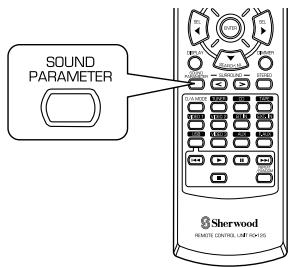
text_image
SOUND PARAMETER Sherwood REMOTE CONTROL LIME FROM US- Then "NIGHT : \~" (or "PANO : \~") is displayed for several seconds.
- If the parameter mode disappears, press this button again.
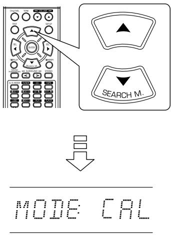
2. Press the CURSOR UP(▲)/DOWN(▼) buttons to select the desired parameter.
text_image
DOWN TIME ON/OFF OFF ON/OFF ON/OFF ON/OFF ON/OFF ON/OFF ON/OFF ON/OFF ON/OFF ON/OFF ON/OFF ON/OFF ON/OFF ON/OFF ON/OFF ON/OFF ON/OFF ON/OFF ON/OFF ON/OFF ON/OFF ON/OFF ON/OFF ON/OFF ON/OFF ON/OFF ON/OFO ON/OFO ON/OFO ON/OFO ON/OFO ON/OFO ON/OFO ON/OFO ON/OFO ON/OFO ON/OFO ON/OFO ON/OFO ON/OFO ON/OFO ON/OFO ON/OFO ON/OFO ON/OFO ON/OFO ON/OFO ON/OFO ON/OFO ON/OFO ON/OFO ON/OO ON/OO ON/OO ON/OO ON/OO ON/OO ON/OO ON/OO ON/OO ON/OO ON/OO ON/OO ON/OO ON/OO ON/OO ON/OO ON/OO ON/OO ON/OO ON/OO ON/OO ON/OO ON/OO ON/OO ON/OO ON/OOO ON/OOO ON/OOO ON/OOO ON/OOO ON/OOO ON/OOO ON/OOO ON/OOO ON/OOO ON/OOO ON/OOO ON/OOO ON/OOO ON/OOO• Each time these buttons are pressed, the parameter mode changes as follows:

flowchart
graph LR
    A["NIGHT"] --> B["PANO"]
    B --> C["C.WIDTH"]
    C --> D["DIMEN"]
    style A fill:#f9f,stroke:#333
    style B fill:#ccf,stroke:#333
    style C fill:#cfc,stroke:#333
    style D fill:#fcc,stroke:#333
- "NIGHT" can be selected only while playing digital signals from Dolby Digital source.
- "PANO", "C.WIDTH" and "DIMEN" can be selected only while listening in Dolby Pro Logic II Music mode.
4. Repeat the above steps 2 and 3 to adjust other parameters.
3. Press the CURSOR LEFT(◀)/RIGHT(▶) buttons to adjust the selected parameter as desired.
text_image
SEL SEL■ When selecting the "NIGHT (Night mode)"
This function compresses the dynamic range of previously specified parts of Dolby Digital sound track (with extremely high volume) to minimize the difference in volume between the specified and non-specified parts. This makes it easy to hear all of the sound track when watching movies at night at low levels. The night mode can be set in 11 steps from 0.0 to 1.0 (default value: 0.0).
■Note : In some Dolby Digital softwares, the night mode may not be valid.
■ When selecting the "PANO (Panorama)" mode
This mode extends the front stereo image to include the surround speakers for an exciting "wraparound" effect with side wall imaging.
Select "OFF" or "ON"(default value: OFF).
■ When selecting the "C. WIDTH (Center width)" control
This adjusts the center image so it may be heard only from the center speaker, only from the left/right speakers as a phantom image, or from all three front speakers to varying degrees.
The control can be set in 8 steps from 0 to 7(default value : 3).
■ When selecting the "DIMEN (Dimension)" control
This gradually adjusts the soundfield either towards the front or towards the rear. The control can be set in 7 steps from -3 to +3 (default value : 0).
Adjusting each channel level with test tone
- The volume level of each channel can be adjusted easily with the test tone function.
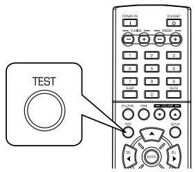
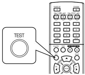
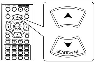
1. Enter the test tone mode.
text_image
TEST RANGE-ON STRAW OFF START START START START STARTTEST
- The test tone mode is displayed and will be heard from the speaker of each channel for 2 seconds as follows:
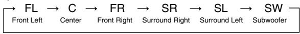
flowchart
graph LR
    A["FL"] --> B["C"]
    B --> C["FR"]
    C --> D["SR"]
    D --> E["SL"]
    E --> F["SW"]
    style A fill:#f9f,stroke:#333
    style F fill:#f9f,stroke:#333
    subgraph Front Left
        A
        B
        C
    end
    subgraph Center
        B
        C
        D
    end
    subgraph FR Right
        C
        D
        E
    end
    subgraph Surround Right
        D
        E
    end
    subgraph Surround Left
        E
        F
    end
- When the speaker setting is "N (None or No)", the test tone of the corresponding channel is not available.
- At each channel, adjust the level as desired until the sound level of each speaker is heard to be equally loud.

text_image
Diagram showing a remote control interface with two 'SEL' buttons and directional arrows pointing to the left panel.- You can select the desired channel with the CURSOR UP(▲)/DOWN(▼) buttons.
- Cancel the test tone function.
text_image
TEST STANDARD 1 2 3 4 5 6 7 8 9 10 11 12 13 14 15 16 17 18 19 20 21 22 23 24 25 26 27 28 29 30 31 32 33 34 35 36 37 38 39 40 41 42 43 44 45 46 47 48 49 50Adjusting the current channel level
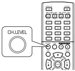
- After adjusting each channel level with test tone, adjust the channel levels either according to the program sources or to suit your tastes.
- You can adjust the current channel levels as desired. These adjusted levels are just memorized into user's memory ("CAL"), not into preset memory("REF 1", "REF 2").
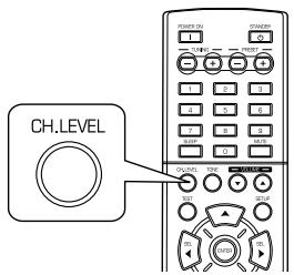
1. Press the CHANNEL LEVEL button.
text_image
CH. LEVEL
- Then the memory mode ("CAL", etc.) is displayed for several seconds.
- When the memory mode or channel level disappears, press this button again.
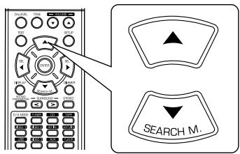
2. Select the desired channel.
text_image
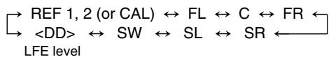
ON/OFF ON/OFF ON/OFF ON/OFF ON/OFF ON/OFF ON/OFF ON/OFF ON/OFF ON/OFF ON/OFF ON/OFF ON/OFF ON/OFF ON/OFF ON/OFF ON/OFF ON/OFF ON/OFF ON/OFF ON/OFF ON/OFF ON/OFF ON/OFF ON/OFF ON/OFF• Each time these buttons are pressed, the corresponding channel is selected as follows:
flowchart
graph TD
    A["REF 1, 2 (or CAL)"] <--> B["FL"]
    B <--> C["C"]
    C <--> D["FR"]
    E["DD"] <--> F["SW"]
    F <--> G["SL"]
    G <--> H["SR"]
    I["LFE level"]
<>: Only when the digital signals from Dolby Digital program sources that include LFE signal are input, LFE level can be displayed.
- Depending on the speaker settings ("N (None or No)") and surround mode, etc., some channels cannot be selected.
3. Adjust the level of the selected channel as desired.
text_image
Diagram showing a remote control interface with two labeled 'SEL' buttons, one pointing to the left panel and the other to the right panel.- The LFE level can be adjusted within the range of -10\~0 dB and other channel levels within the range of -15 \~ +15 dB.
- In general, we recommend the LFE level to be adjusted to 0 dB. If the recommended levels seem too high, lower the setting as necessary.
4. Repeat the above steps 2 and 3 to adjust each channel level.
Memorizing the adjusted channel levels
- You can memorize the adjusted channel levels into preset memory("REF 1", "REF 2") and recall the memorized whenever you want.
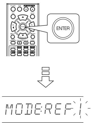
- After performing the steps 1 \~ 4 in "Adjusting the current channel level" procedure on page 18, press the ENTER button.
text_image
ENTER
- Then "1" of "REF 1" indication flickers for several seconds.
- Select the desired one of REF 1 and REF 2.
text_image
Diagram showing a remote control interface with two 'SEL' buttons and directional arrows pointing to the left panel.- If the preset memory disappears, perform the above step 1 again.
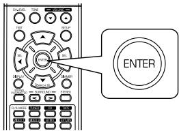
- Confirm your selection.
text_image
ENTERRecalling the memorized channel levels
- The adjusted channel levels have now been memorized into the selected memory.
- Press the CHANNEL LEVEL button.
text_image
CH.LEVEL- "CAL" (or "REF 1", etc.) is displayed for several seconds.
-
If the channel level mode display disappears, press this button again.
-
Select the desired one of REF 1 and REF 2.

text_image
Diagram showing a remote control interface with labeled buttons and two 'SEL' button options- Then the channel levels memorized into the selected preset memory are recalled.
LISTENING TO RADIO BROADCASTS
Auto tuning
1. Select the desired band.
text_image
BAND or TUNER Sherwood REMOTE CONTROL SNR/ROCKS F M 97.50 MHz BAND FREQUENCY• Each time this button is pressed, the band changes as follows;
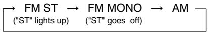
- When FM stereo broadcasts are poor because of weak broadcast signals, select the FM mono mode to reduce the noise, then FM broadcasts are reproduced in monaural sound.
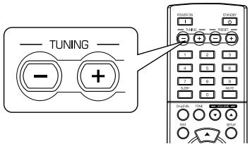
Manual tuning
- Manual tuning is useful when you already know the frequency of the desired station.
- After selecting the desired band, press the TUNING UP(+) / DOWN(-) buttons repeatedly until the right frequency has been reached.
text_image
TUNING - +2. Press the TUNING UP(+)/DOWN(-) buttons for more than 0.5 second.
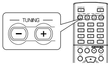
text_image
TUNING - +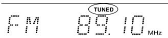
- The tuner will now search until a station of sufficient strength has been found. The display shows the tuned frequency and "TUNED".
- If the station found is not the desired one, simply repeat this operation.
- Weak stations are skipped during auto tuning.
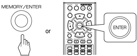
Auto presetting
- Auto presetting function automatically searches for FM stations only and store them in the memory.
- While listening to radio broadcasts, press and hold down the (MEMORY/) ENTER button for more than 2 seconds.
text_image
MEMORY/ENTER or ENTER ENTER- Then "AUTO MEM" flickers and this receiver starts auto presetting.
- Up to 30 FM stations can be stored.
Notes:
- FM stations of weak strength cannot be memorized.
- To memorize AM stations or weak stations, preform "Manual presetting" procedure with using "Manual tuning" operation.
Manual presetting
- You can store up to 30 preferred stations in the memory.
-
Tune in the desired station with auto or manual tuning.
-
Press the ENTER button.
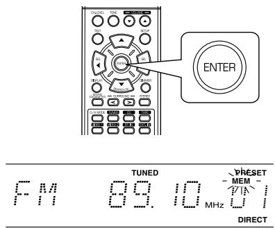
text_image
TUNED PRÉSET MEM FM 89.10 MHz DIRECT- "MEM" is flickering for several seconds.
- Select the desired preset number (1\~30) and press the ENTER button.
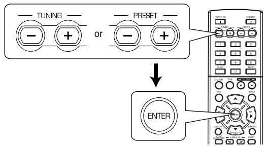
flowchart
graph TD
    A["--- Tuning"] --> B["--- or +"]
    C["--- PRESET"] --> D["--- or +"]
    B --> E["↓"]
    D --> E
    E --> F["ENTER"]
- When using the NUMERIC buttons on the remote control.
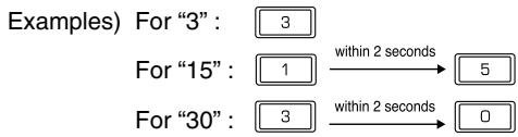
flowchart
graph TD
    A["Examples) For "3": 3"] --> B["For "15": 1"]
    B --> C["within 2 seconds"] --> D["5"]
    E["For "30": 3"] --> F["within 2 seconds"] --> G["0"]
- The station has now been stored in the memory.
- When using the NUMERIC buttons, the station is stored automatically without pressing the ENTER button.
- A stored frequency is erased from the memory by storing another frequency in its place.
-
If "MEM" goes off, start again from the above step 2.
-
Repeat the above steps1 to 3 to memorize other stations.
The following items, set before the receiver is turned off, are memorized.
- INPUT SELECTOR settings
- Surround mode settings
- Preset stations,etc.
Tuning to preset stations
- After selecting the tuner as an input source, select the desired preset number.
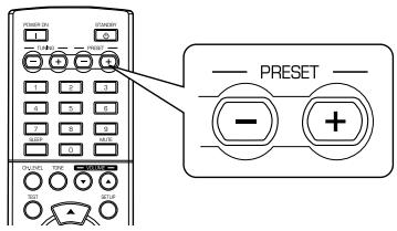
text_image
PRESET - +- When using the NUMERIC buttons on the remote control.
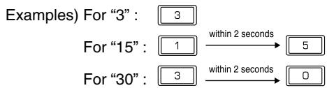
flowchart
graph LR
    A["Examples) For "3": 3"] --> B["For "15": 1"]
    B -->|within 2 seconds| C["5"]
    D["For "30": 3"] -->|within 2 seconds| E["0"]
RDS Tuner (Regional Option for some countries in Europe, etc.)
LISTENING TO RDS BROADCASTS(FM ONLY)
RDS(Radio Data System) is a method for sending information signals together with the transmitter signals. Your tuner is capable of translating these signals and putting the information on the display. These codes contain the following informations. Program Service name (PS), A list of Program Types (PTY), Traffic Announcement (TA), Clock Time (CT), Radio Text (RT).
■ Note : In the other countries, RDS tuner function cannot be available.
RDS search
- Use this function to automatically search and receive the stations offering RDS services.
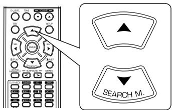
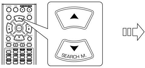
1. In the FM mode, select the RDS search mode.
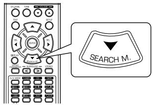
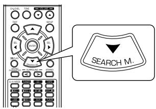
text_image
SEARCH M.
text_image
• Each time this button is pressed, the search mode changes as follows; → RDS SRCH → TP SRCH → PTY SRCH → OFF —2. When "RDS SRCH" is displayed, press the ENTER button.

text_image
ENTER- The tuner automatically searches stations offering RDS services and the station name is displayed.
- If no RDS station is found, "NO RDS" is displayed.
- When "RDS SRCH" is not displayed, repeat again from the above step 1.
TP search
- Use this function to automatically search and receive the stations broadcasting the traffic program.
1. In the FM mode, press the SEARCH MODE button twice.
text_image
SEARCH M.- "TP SRCH" is displayed.
2. When "TP SRCH" is displayed, press the ENTER button.


text_image
ENTER- The tuner automatically searches for stations broadcasting the traffic program.
- "NO TRAFF" is displayed if the signal is too weak or there are no stations broadcasting the traffic program.
- When "TP SRCH" is not displayed, repeat again from the above step 1.
PTY search
- Use this function to automatically search and receive the stations broadcasting the desired program type.
- In the FM mode, press the SEARCH MODE button three times.
text_image
SEARCH M.PTY SRACH
- "PTY SRCH" is displayed.
- When "PTY SRCH" is displayed, select the desired program type.
text_image
Diagram showing a remote control interface with two 'SEL' buttons and directional arrows pointing to the left panel.NEWS
• Each time these buttons are pressed, one of 32 different types of programs is selected.
(NEWS, AFFAIRS, INFO, SPORT, EDUCATE, DRAMA, CULTURE, SCIENCE, VARIED, POP M, ROCK M, EASY M, LIGHT M, CLASSICS, OTHER M, WEATHER, FINANCE, CHILDREN, SOCIAL, RELIGION, PHONE IN, TRAVEL, LEISURE, JAZZ, COUNTRY, NATION M, OLDIES, FOLK M, DOCUMENT, TEST, ALARM, NONE)
- When "PTY SRCH" is not displayed, repeat again from the above step 1.
- When the desired program is displayed, press the ENTER button.
text_image
ENTERDISPLAY
In the FM mode,
text_image
DISPLAY Sherwood REMOTE CONTROL LIMITS:625- The tuner automatically searches a station offering PTY services.
- If no station is found, "NO PROG" is displayed.
• Each time this button is pressed, the display mode changes as follows:
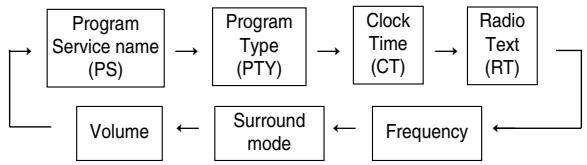
flowchart
graph LR
    A["Program Service name (PS)"] --> B["Program Type (PTY)"]
    B --> C["Clock Time (CT)"]
    C --> D["Radio Text (RT)"]
    D --> E["Frequency"]
    E --> F["Surround mode"]
    F --> G["Volume"]
    G --> A
- If the signals are too weak or no RDS service is available, "NO NAME", "NO PTY", "NO TIME" or "NO TEXT" will be displayed.
RECORDING
- When recording the analog signals from CD or VIDEO 1, be sure to select the analog input.
(For details, refer to "When CD, VIDEO 1 is selected as an input source" on page 12.) - The volume and tone (bass, treble) settings have no effect on the recording signals.
- When you select tuner, CD or VIDEO 2 as a recording source, recording may be made on TAPE, VIDEO 1 or both simultaneously.
Recording with TAPE
- Select the desired input as a recording source except for TAPE.
text_image
BAND or MULTI CONTROL INPUT SELECTOR or TUNER CD VIDEO 1 VIDEO 2 Sherwood REMOTE CONTROL UNIT 10-15-
Start recording on the TAPE.
-
Start play on the desired input.
Recording with VIDEO 1
- When the audio recording equipment is connected to the VIDEO 1 jacks, you can record the audio signals.
- Select the desired input as a recording source except for VIDEO 1.

text_image
BAND or MULTI CONTROL INPUT SELECTOR or TUNER CD TAPE VIDEO 2 Sherwood REMOTE CONTROL UNIT 150-125-
Start recording on the VIDEO 1.
-
Start play on the desired input.
OTHER FUNCTIONS
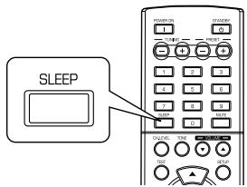
Operating the sleep timer
- The sleep timer allows the system to continue to operate for a specified period of time before automatically shutting off.
- To set the receiver to automatically turn off after the specified period of time.
text_image
SLEEPAdjusting the brightness of the fluorescent display
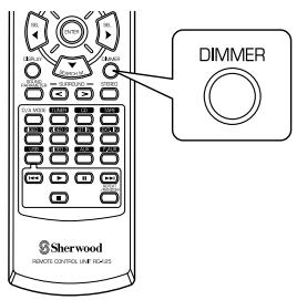
text_image
DIMMER Sherwood REMOTE CONTROL LINE EC425• Each time this button is pressed, the brightness of the fluorescent display changes as follows:
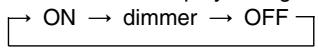
- In the display OFF mode, pressing any button will restore the display ON mode.
• Each time this button is pressed, the sleep time changes as follows:
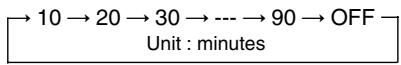
- While operating the sleep timer, " ★ ) " lights up.
- When the sleep time is selected, the fluorescent display is dimly lit.
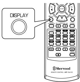
Displaying the operation status
During playback,
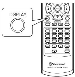
text_image
DISPLAY Sherwood REMOTE CONTROLS UP THE HEADS• Each time this button is pressed, the display mode changes as follows:
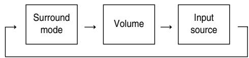
flowchart
graph LR
    A["Surround mode"] --> B["Volume"]
    B --> C["Input source"]
    C --> A
- When RDS tuner function is available in your country, for details on the FM mode information, see "DISPLAY" on page 23.
USING DIFFERENT FUNCTIONS ON THE FRONT PANEL
- You can use the different functions easily with the specific buttons on the front panel.
1. Select the desired setting mode.

- Depending on the selected input source, each time this button is pressed, the mode changes as follows and is displayed for several seconds:
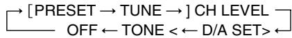
(Current input display)
[] : Selectable only when the tuner is selected.
<>: Selectable only when the CD or VIDEO 1 is selected.
2. Enter the selected mode.

- The setting mode will be cancelled in several seconds. Should this happened, perform the above step 1 again.
3. Set the selected mode as desired.

flowchart
graph TD
    A["INPUT SELECTOR"] --> B["MULTI CONTROL"]
    B --> A
■ When selecting “PRESET” (Preset tuning mode)
- Each time this knob is rotated, the preset station will be tuned to.(For details, refer to “Tuning to preset stations” on page 21.)
■ When selecting “TUNE” (Auto/manual tuning mode)
- Depending on whether this knob is rotated over several steps once or one by one slowly, Auto tuning or manual tuning will function. (For details, refer to “Auto tuning” and “Manual tuning” on page 20.)
■ When selecting “CH LEVEL” (Channel level adjustment mode)
- You can adjust the current channel levels as desired. (For details, refer to “Adjusting the current channel level” on page 18.)
① Press the MODE button to select the desired channel.
② Rotate this knob to adjust the level of the selected channel as desired.
③ Repeat the above steps ① and ② to adjust each channel level.
■ When selecting "D/A SET" (Digital/Analog input mode)
- Each time this knob is rotated, the digital(optical or coaxial) or the analog input will be selected.(For details, refer to “When CD, VIDEO 1 is selected as an input source” on page 12.)
■ When selecting “TONE” (Tone adjustment mode)
• Each time this knob is rotated, the tone mode is selected as follows:
OFF : To listen to a program source without the tone effect.
(“DIRECT” indicator lights up.)
ON : To adjust the tone for your taste. ("DIRECT" indicator goes off.)
◆ When the TONE is set to ON to adjust the tone (bass and treble)
① Press the MODE button to select the desired tone.
② Rotate this knob to adjust the selected tone as desired.
③ To complete tone adjustment, repeat the above steps ① and ②.
4. Exit the setting mode.
MEMORY/ENTER


System Setup
- The setup menu is displayed on the fluorescent display and allows you to perform the setup procedures easily. In most situations, you will only need to set this once during the installation and layout of your home theater, and it rarely needs to be changed later.
The setup menu consists of 5 main menus; system, input, speaker setup, CH level and parameter. These menus are then divided up into various sub-menus.
1. Turn the setup menu on.
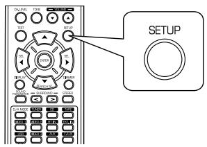
text_image
SETUPSYSTEM
- The setup menu will be shown.
- To turn the menu off, press this button again.
3. Confirm your selection.
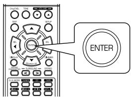
text_image
ENTER2. Select the desired menu using the CURSOR UP(▲)/DOWN(▼) buttons.
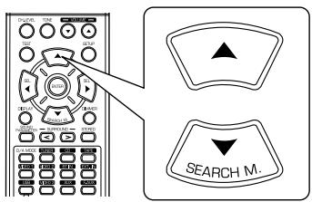
text_image
DC ON OFF ON OFF ON OFF ON ON ON ON ON ON ON ON ON ON ON ON ON ON ON ON ON ON ON ON ON ON ON ON ON ON ON ON ON ON ON ON ON ON ON ON ON ON ON ON ON ON ON ON ON ON ON ON ON ON ONE ON ONE ON ONE ON ONE ON ONE ON ONE ON ONE ON ONE ON ONE ON ONE ON ONE ON ONE ON ONE ON ONE ON ONE ON ONE ON ONE ON ONE ON ONE ON ONE ON ONE ON ONE ON ONE ON ONE ON ONE ON ONE ON ONE ON ONE ON ONE ON ONE ON ONE ON ONE ON ONE ON ONE ON- When selecting "SYSTEM", see "SETTING THE SYSTEM" on page 29.
- When selecting "INPUT", see "SETTING THE INPUT" on page 31.
- When selecting "SPK SET", see "SETTING THE SPEAKER SETUP" on page 32.
- When selecting "CH LEVEL", see "SETTING THE CH LEVEL" on page 36.
- When selecting "PARAMTR", see "SETTING THE PARAMETER" on page 38.
- When selecting "EXIT", the setup menu will be turned off.
■ Setup menu flow
- The setup menu flow is as follows :
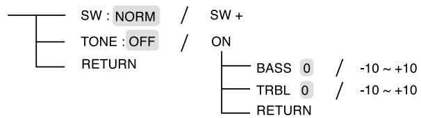
◆ SYSTEM
text_image
SW : NORM / SW + TONE : OFF / ON RETURN BASS 0 / -10 ~ +10 TRBL 0 / -10 ~ +10 RETURN
: Default settings
◆ INPUT

flowchart
graph TD
    A["VID 1 CFG"] --> B["D.IN : OPT / COAX / ANL"]
    A --> C["AUTO : OFF / ON"]
    A --> D["RETURN"]
    E["CD CFG"] --> F["D.IN : OPT / COAX / ANL"]
    E --> G["AUTO : OFF / ON"]
    E --> H["RETURN"]
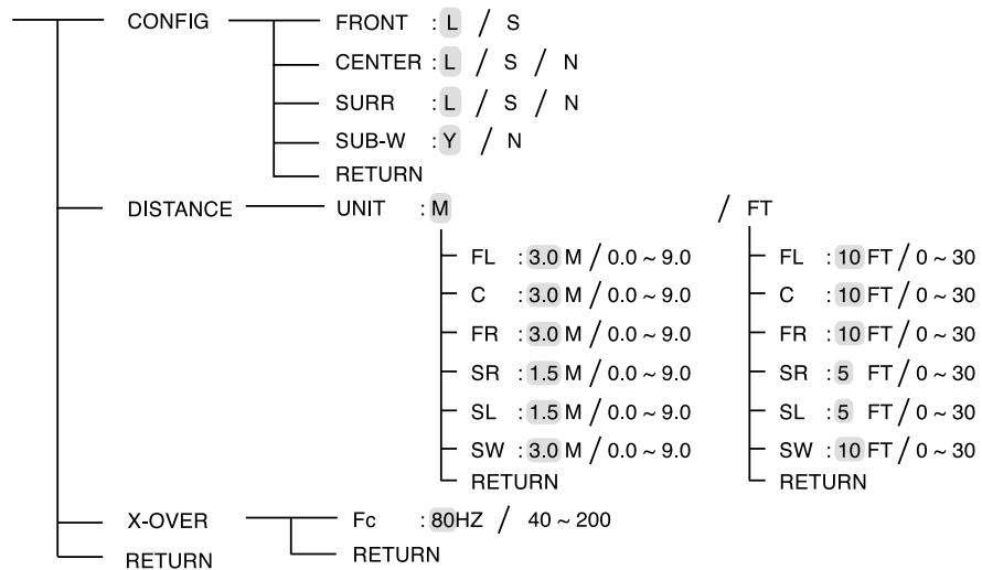
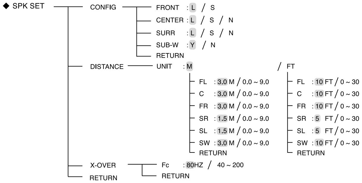
◆ SPK SET
flowchart
graph TD
    A["CONFIG"] --> B["FRONT : L / S"]
    A --> C["CENTER : L / S / N"]
    A --> D["SURR : L / S / N"]
    A --> E["SUB-W : Y / N"]
    A --> F["RETURN"]
    G["DISTANCE"] --> H["UNIT : M"]
    H --> I["FL : 3.0 M / 0.0 ~ 9.0"]
    H --> J["C : 3.0 M / 0.0 ~ 9.0"]
    H --> K["FR : 3.0 M / 0.0 ~ 9.0"]
    H --> L["SR : 1.5 M / 0.0 ~ 9.0"]
    H --> M["SL : 1.5 M / 0.0 ~ 9.0"]
    H --> N["SW : 3.0 M / 0.0 ~ 9.0"]
    H --> O["RETURN"]
    P["X-OVER"] --> Q["Fc : 80HZ / 40 ~ 200"]
    P --> R["RETURN"]
    I --> S["FL : 10 FT / 0 ~ 30"]
    I --> T["C : 10 FT / 0 ~ 30"]
    I --> U["FR : 10 FT / 0 ~ 30"]
    I --> V["SR : 5 FT / 0 ~ 30"]
    I --> W["SL : 5 FT / 0 ~ 30"]
    I --> X["SW : 10 FT / 0 ~ 30"]
    I --> Y["RETURN"]
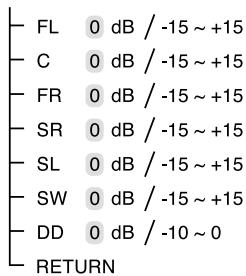
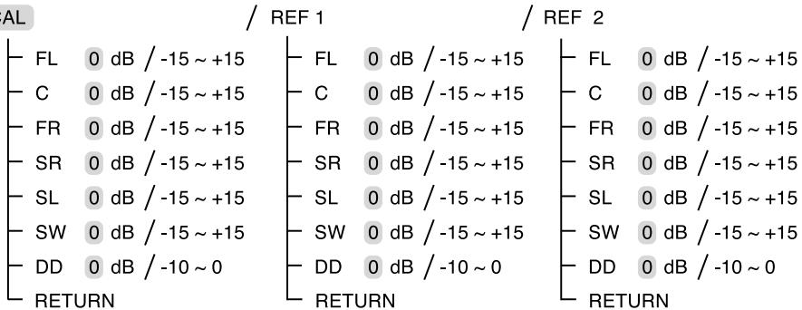
◆ CH LEVEL
MODE : CAL
text_image
FL 0 dB / -15 ~ +15 C 0 dB / -15 ~ +15 FR 0 dB / -15 ~ +15 SR 0 dB / -15 ~ +15 SL 0 dB / -15 ~ +15 SW 0 dB / -15 ~ +15 DD 0 dB / -10 ~ 0 RETURN/ REF 1

text_image
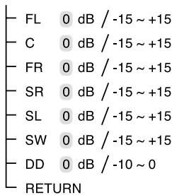
FL 0 dB / -15 ~ +15 C 0 dB / -15 ~ +15 FR 0 dB / -15 ~ +15 SR 0 dB / -15 ~ +15 SL 0 dB / -15 ~ +15 SW 0 dB / -15 ~ +15 DD 0 dB / -10 ~ 0 RETURN/ REF 2
text_image
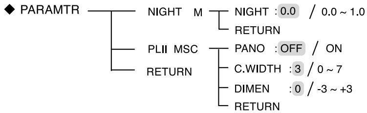
FL 0 dB / -15 ~ +15 C 0 dB / -15 ~ +15 FR 0 dB / -15 ~ +15 SR 0 dB / -15 ~ +15 SL 0 dB / -15 ~ +15 SW 0 dB / -15 ~ +15 DD 0 dB / -10 ~ 0 RETURN◆ PARAMTR
flowchart
graph TD
    A["NIGHT M"] --> B["NIGHT : 0.0 / 0.0 ~ 1.0"]
    A --> C["RETURN"]
    D["PLII MSC"] --> E["PANO : OFF / ON"]
    D --> F["RETURN"]
    E --> G["C.WIDTH : 3 / 0 ~ 7"]
    E --> H["DIMEN : 0 / -3 ~ +3"]
    E --> I["RETURN"]
◆ EXIT
- When "RETURN" is selected on a sub-menu, it will returns to the previous menu.
■ Note : During setup menu operation, only the (POWER ON/) STANDBY button and the buttons required for system setup will function.
SETTING THE SYSTEM
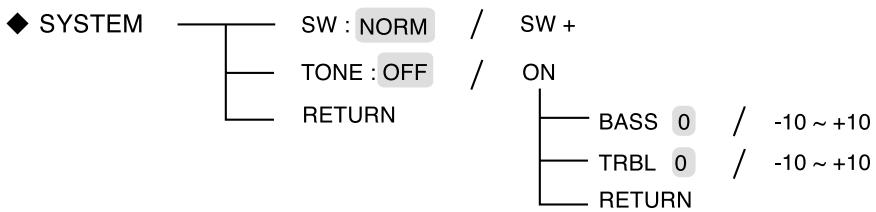
flowchart
graph TD
    A["◆ SYSTEM"] --> B["SW : NORM"]
    B --> C["/"]
    B --> D["TONE : OFF"]
    D --> E["/"]
    D --> F["ON"]
    F --> G["BASS 0 / -10 ~ +10"]
    F --> H["TRBL 0 / -10 ~ +10"]
    F --> I["RETURN"]
    I --> J["RETURN"]
- SW (SUBWOOFER) : To select the desired subwoofer mode.
- TONE : To adjust the tone (bass and treble) as desired.
-
RETURN: To return to the previous menu.
-
Press CURSOR UP(▲)/DOWN(▼) buttons to select the desired item.

text_image
ONION ONION ONION ONION ONION ONION ONION ONION ONION ONION ONION ONION ONION ONION ONION ONION ONION ONION ONION ONION ONION ONION ONION ONION ONION ONION ONION ONION ONION ONION ONION ONION ONION ONION OR OR OR OR OR OR OR OR OR OR OR OR OR OR OR OR OR OR OR OR OR OR OR OR OR OR OR OR OR OR OR OR OR OR OR OR OR OR OR OR OR OR OR OR OR OR OR OR OR OR O30000000000000000000000000000000000000000000000000000000000000000000000000000000000000000000000000000- Press the CURSOR LEFT(◀)/RIGHT(▶) buttons to set the selected item as desired

text_image
Diagram showing a remote control interface with two 'SEL' buttons and directional arrows pointing to the left panel.When selecting the SUBWOOFER mode
- "SW +" mode is effective only when "FRONT", "CENTER" or "SURR" is set to "L" and "SUB-W" is set to "Y" on the SPK SET menu. (For details, refer to "SETTING THE SPEAKER SETUP" on page 32.)
- While playing the 2 channel source in MATRIX, CHURCH, THEATER, HALL or STADIUM mode, the low frequency signals can be reproduced from subwoofer regardless of the subwoofer mode setting.
NORM : When the low frequency signals of channels set to "L" are reproduced from those channels only.
In this mode, the low frequency signals that are reproduced from the subwoofer channel is only the low frequency signals of LFE (from the multi-channel sources that contains LFE (Low Frequency Effects) channel, also called the ".1" channel) and the channels set to "S".
SW +: When the low frequency signals of channels set to "L" are reproduced simultaneously from those channels and the subwoofer channel.
In this mode, the low frequency range expands more uniformly through the room, but depending on the size and shape of the room, interference may result in a decrease of the actual volume of the low frequency range.
OFF : To listen to a program source without the tone effect. ("DIRECT" indicator lights up.)
↑↓
ON : To adjust the tone for your taste. ("DIRECT" indicator goes off.)
■ When the TONE is set to ON to adjust the tone (bass and treble)
① Press the CURSOR UP(▲)/DOWN(▼) buttons to select the desired tone.
text_image
ON/OFF ON/OFF OFF ON/OFF ON/OFF ON/OFF ON/OFF ON/OFF ON/OFF ON/OFF ON/OFF ON/OFF ON/OFF ON/OFF ON/OFF ON/OFF ON/OFF ON/OFF ON/OFF ON/OFF ON/OFF ON/OFF ON/OFF ON/OFF ON/OFF ON/OFF ON/OFF ON/OFF ON/OFO ON/OFO ON/OFO ON/OFO ON/OFO ON/OFO ON/OFO ON/OFO ON/OFO ON/OFO ON/OFO ON/OFO ON/OFO ON/OFO ON/OFO ON/OFO ON/OFO ON/OFO ON/OFO ON/OFO ON/OFO ON/OFO ON/OFO ON/OFO ON/OFO ON/OFF ON/OFF ON/OFF ON/OFF ON/OFF ON/OFF ON/OFF ON/OFF ON/OFF ON/OFF ON/OFF ON/OFF ON/OFF ON/OFF ON/OFF ON/OFF ON/OFF ON/OFF ON/OFF ON/OFF ON/OFF ON/OFF ON/OFF ON/OFF ON/OF ON/OF ON/OF ON/OF ON/OF ON/OF ON/OF ON/OF ON/OF ON/OF ON/OF ON/OF ON/OF ON/OF ON/OF ON/OF ON/OF ON/OF ON/OF ON/OF ON/OF ON/OF ON/OF ON/OF ON/OF ON/OFO
When selecting the BASS

② Press the CURSOR LEFT(◀)/RIGHT(▶) buttons to adjust the selected tone as desired.

text_image
SEL SEL- The tone level can be adjusted within the range of -10 \~ +10 dB.
- In general, we recommend the bass and treble to be adjusted to 0 dB (flat level).
- Extreme settings at high volume may damage your speakers.
- To complete tone adjustment, repeat the above steps ① and ②.
SETTING THE INPUT
◆ INPUT
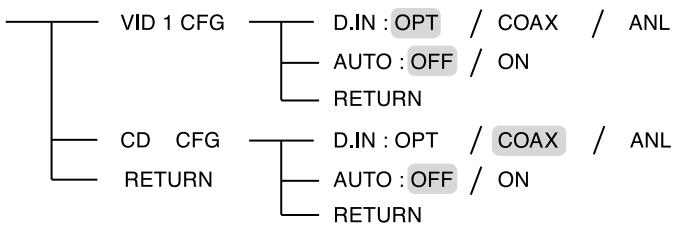
flowchart
graph TD
    A["VID 1 CFG"] --> B["D.IN : OPT / COAX / ANL"]
    A --> C["AUTO : OFF / ON"]
    A --> D["RETURN"]
    E["CD CFG"] --> F["D.IN : OPT / COAX / ANL"]
    E --> G["AUTO : OFF / ON"]
    E --> H["RETURN"]
• D.IN (DIGITAL IN) : To assign the connected DIGITAL INs to the desired input.
- AUTO (AUTO SURROUND) : To select the auto surround mode or the manual surround mode.
- RETURN: To return to the previous menu.
- Press the CURSOR UP(▲)/DOWN(▼) buttons to select the desired input source, then press the ENTER button.

flowchart
graph TD
    A["Remote Control Panel"] --> B["Search Mode"]
    B --> C["ENTER"]
    style A fill:#f9f,stroke:#333
    style B fill:#ccf,stroke:#333
    style C fill:#cfc,stroke:#333

Example) When selecting the CD

- Press the CURSOR UP(▲)/DOWN(▼) buttons to select the desired item.
text_image
ON/OFF ON/OFF ON/OFF ON/OFF ON/OFF ON/OFF ON/OFF ON/OFF ON/OFF ON/OFF ON/OFF ON/OFF ON/OFF ON/OFF ON/OFF ON/OFF ON/OFF ON/OFF ON/OFF ON/OFF ON/OFF ON/OFF ON/OFF ON/OFF ON/OFF ON/OFF- Press the CURSOR LEFT(◀)/RIGHT(▶) buttons to set the selected item as desired.
text_image
SEL SELWhen selecting the DIGITAL IN
- You should assign the connected DIGITAL INs to the desired of CD and VIDEO 1. (For details, refer to "CONNECTING DIGITAL INs" on page 5.)
- You can select the desired of OPT (optical), COAX(coaxial) and ANL (analog).
Notes :
- In such a case that a DIGITAL IN is assigned to two input sources or more, when these input sources are selected, the digital audio signals can be heard from the same DIGITAL IN.
- When TUNER, TAPE or VIDEO 2 is selected as an input source, the digital input("OPT", "COAX") cannot be selected.
When selecting the AUTO SURROUND
- Depending on how to select a surround mode, you can select the auto surround mode or the manual surround mode. OFF (Manual surround mode): You can select the desired of different surround modes selectable for the signal being input with using the SURROUND MODE UP/DOWN (▶, >/◀, <) buttons. (For details, refer to "ENJOYING SURROUND SOUND" on page 15.)
ON (Auto surround mode) : The optimum surround mode will be automatically selected depending on the signal format being input.
Notes :
- Even when the auto surround mode is selected and the same type of digital signal format is being input, the optimum surround mode may vary depending on whether the speaker type is set to "N (None)" or not.
- When 96 kHz PCM digital signal is being input, only the stereo mode will be selected.
SETTING THE SPEAKER SETUP
- After you have installed this receiver and connected all the components, you should adjust the speaker settings for the optimum sound acoustics according to your environment and speaker layout.
- Even when you change speakers, speaker positions, or the layout of your listening environment, you should adjust the speaker settings, too.
flowchart
graph TD
    A["◆ SPK SET"] --> B["CONFIG"]
    B --> C["FRONT : L / S"]
    B --> D["CENTER : L / S / N"]
    B --> E["SURR : L / S / N"]
    B --> F["SUB-W : Y / N"]
    B --> G["RETURN"]
    A --> H["DISTANCE"]
    H --> I["UNIT : M"]
    I --> J["FL : 3.0 M / 0.0 ~ 9.0"]
    I --> K["C : 3.0 M / 0.0 ~ 9.0"]
    I --> L["FR : 3.0 M / 0.0 ~ 9.0"]
    I --> M["SR : 1.5 M / 0.0 ~ 9.0"]
    I --> N["SL : 1.5 M / 0.0 ~ 9.0"]
    I --> O["SW : 3.0 M / 0.0 ~ 9.0"]
    I --> P["RETURN"]
    A --> Q["X-OVER"]
    Q --> R["Fc : 80HZ / 40 ~ 200"]
    Q --> S["RETURN"]
    I --> T["/ FT"]
    T --> U["FL : 10 FT / 0 ~ 30"]
    T --> V["C : 10 FT / 0 ~ 30"]
    T --> W["FR : 10 FT / 0 ~ 30"]
    T --> X["SR : 5 FT / 0 ~ 30"]
    T --> Y["SL : 5 FT / 0 ~ 30"]
    T --> Z["SW : 10 FT / 0 ~ 30"]
    T --> AA["RETURN"]
- CONFIG (CONFIGURATION) : To select the sizes of the speakers that are connected.
- DISTANCE: To enter the distance between the listening position and each speaker to set the delay time automatically for optimum surround playback.
- X-OVER (CROSSOVER) : To select the desired crossover frequency.
-
RETURN : To return to the previous menu.
-
Press the CURSOR UP(▲)/DOWN(▼) buttons to select the "CONFIG", then press the ENTER button.

flowchart
graph TD
    A["Left Panel"] --> B["Search Mode"]
    B --> C["ENTER"]
    D["Down Arrow"] --> E["FRONT: L"]
- Press the CURSOR UP(▲)/DOWN(▼) buttons to select the desired speaker.
text_image
Digital Control Signal Display Search M.- Press the CURSOR LEFT(◀)/RIGHT(▶) buttons to set the selected speaker as desired.

text_image
Diagram showing a remote control with labeled buttons and two 'SEL' buttons, likely illustrating a selection or navigation interface.- Depending on your speaker type, you can select one of these following speaker types. L(Large): Select this when connecting speakers that can fully reproduce sounds below crossover frequency.
S(Small) : Select this when connecting speakers that can not fully reproduce sounds below crossover frequency. When this is selected, sounds below crossover frequency are sent to the subwoofer or speakers which are set to "L (Large)" (when not using a subwoofer)
N(None): Select this when no speakers are connected. When this is selected, sounds are sent to the speakers which are not set to "N (None)".
Y(Yes)/N(No): Select the desired depending on whether a subwoofer is connected or not.
Notes :
- When speakers are set to "S (Small)", you should set their crossover frequency correctly according to their frequency characteristics. (For details, refer to "When selecting the CROSSOVER" on page 35.)
- When "SUB-W" is set to "N (No)", "FRONT" is automatically set to "L (Large)".
-
When the "FRONT" is set to "S (Small)", "CENTER" and "SURR" cannot be set to "L (Large)".
-
Repeat the above steps 2 and 3 until the speakers are all set to the desired mode.
■ About the speaker size
- Select "L (Large)" or "S (Small)" not according to the actual size of the speaker but according to the speaker's capacity for playing low frequency (bass sound below frequency set on the "X-OVER" menu) signals.
-
If you do not know, try comparing the sound at both settings (setting the volume to a level low enough so as not to damage the speakers) to determine the proper setting.
-
Press the CURSOR UP(▲)/DOWN(▼) buttons to select the DISTANCE, then press the ENTER button.
flowchart
graph TD
    A["Left Control Panel"] --> B["Search Button"]
    B --> C["ENTER"]
    style A fill:#f9f,stroke:#333
    style C fill:#ccf,stroke:#333

UNIT : M
- Press the CURSOR UP(▲)/DOWN(▼) buttons to select the desired item.
text_image
OK/Cancel OFF/RESET ON/OFF SELECT ON/OFF SELECT ON/OFF SELECT ON/OFF SELECT ON/OFF SELECT ON/OFF SELECT ON/OFF SELECT ON/OFF SELECT ON/OFF SELECT ON/OFF SELECT ON/OFF SELECT ON/OFF SELECT ON/OFF SELECT ON/OFF SELECT ON/OFF SELECT ON/OFF SELECT ON/OFF SELECT ON/OFF SELECT ON/OFF SELECT ON/OFF SELECT ON/OFF SELECT OR SELECT OR SELECT OR SELECT OR SELECT OR SELECT OR SELECT OR SELECT OR SELECT OR SELECT OR SELECT OR SELECT OR SELECT OR SELECT OR SELECT OR SELECT OR SELECT OR SELECT OR SELECT OR SELECT OR SELECT OR SELECT OR SELECT OR SELECT OR SELECT OR SELECT OR SELECT OR SELECT OR SELECT OR SELECT OR SELECT OR SELECT OR SELECT OR SELECT ORNote :
- You cannot select the speakers set to "N (None or No)".
- Press the CURSOR LEFT(◀)/RIGHT(▶) buttons to set the selected item as desired.
text_image
SEL SEL■ When selecting the desired unit
- You can select either "M (Meter)" or "FT (Feet)".
- Once a unit is selected, the distances are automatically changed in the selected unit.
■ When setting the distance
- You can set the distance within the range of 0.0 \~ 9.0 meters in 0.3 meter intervals (or 0 \~ 30 feet in 1 feet intervals).
- Repeat the above steps 2 and 3 until the distances are all set as desired.
■ About the speaker distance
When enjoying multi-channel surround playback with Dolby Digital sources, etc., it is ideal that the center, surround and subwoofer speakers should be the same distance from the main listening position as the front speakers. By entering the distance between the listening position and each speaker, the delay times of center, surround and subwoofer speakers are automatically adjusted to create an ideal listening environment virtually as if the center, surround and subwoofer speakers were at their ideal locations respectively.
When selecting the CROSSOVER
- When speakers are set to "S (Small)", be sure to set their crossover frequency correctly according to their frequency characteristics.
- Press the CURSOR UP(▲)/DOWN(▼) buttons to select the "X-OVER", then press the ENTER button.

flowchart
graph TD
    A["Left Panel"] --> B["Search M."]
    B --> C["ENTER"]

Fe : 800HZ
- Press the CURSOR LEFT(◀)/RIGHT(▶) buttons to set the crossover frequency as desired.
text_image
Diagram showing a remote control interface with two 'SEL' buttons and directional arrows pointing to the left panel.- You can adjust the crossover frequency within the range of 40 \~ 200 Hz in 10 Hz intervals.
■ About the crossover frequency
- When speakers are set to "S (Small)", low frequencies in those channels that are below the crossover frequency are to output from subwoofer or front speakers which are set to "L (Large)" (when not using a subwoofer).
- Refer to the operating instructions of the speakers to be connected. If the frequency range of your speaker is 100 Hz\~20 kHz, the crossover frequency should be set to 100 Hz(or slightly higher).
SETTING THE CH LEVEL
■ Note : Depending on the speaker settings ("N (None or No)"), some channels cannot be selected.
Adjusting the current channel level
- You can adjust the current channel levels as desired. These adjusted levels are just memorized into user's memory("CAL"), not into preset memory ("REF 1", "REF 2")
-
After adjusting each channel level with test tone, adjust the channel levels either according to the program sources or to suit your tastes. (For details, refer to "Adjusting each channel level with test tone" on page 17.)
-
Press the CURSOR UP(▲)/DOWN(▼) buttons to select the desired channel.
text_image
DUAL ON ON ON ON ON ON ON ON ON ON ON ON ON ON ON ON ON ON ON ON ON ON ON ON ON ON ON ON ON ON ON ON ON ON ON ON ON ON ON ON ON ON ON ON ON ON ON ON ON ON OR OR OR OR OR OR OR OR OR OR OR OR OR OR OR OR OR OR OR OR OR OR OR OR OR OR OR OR OR OR OR OR OR OR OR OR OR OR OR OR OR OR OR OR OR ORExample) When selecting Dolby Digital source's LFE

- Press the CURSOR LEFT(◀)/RIGHT(▶) buttons to adjust the level of the selected channel or program source's LFE as desired.
text_image
SEL SEL- The LFE level can be adjusted within the range of -10 \~ 0 dB and other channel levels within the range of -15 \~ +15 dB
-
In general, we recommend the LFE level to be adjusted to 0 dB. If the recommended levels seem too high, lower setting as necessary.
-
Repeat the above steps 1 and 2 to adjust each channel level.
Memorizing the adjusted channel levels
- You can memorize the adjusted channel levels into preset memory("REF 1", "REF 2") and recall the memorized whenever you want.
- After performing the steps 1 \~ 3 in "Adjusting the current channel level" procedure on page 36, press the ENTER button.
text_image
ENTER MOTORREF:- Then "1" of "REF 1" indication flickers.
- Press the CURSOR LEFT(◀)/RIGHT(▶) buttons to select the desired preset memory, then press the ENTER button.
flowchart
graph LR
    A[" television "] --> B[" SELECT "]
    B --> C[" SELECT "]
    C --> D[" ENTER "]
- Each time the CURSOR LEFT(◀) or RIGHT(▶) button is pressed, "REF 1" or "REF 2" is selected.
- The adjusted channel levels have now been memorized into the selected memory.
Recalling the memorized channel levels
- Press the CURSOR UP(▲)/DOWN(▼) buttons to select the "MODE \~ ".
text_image
DYNAMIC VOLT ON/OFF ON/OFF ON/OFF ON/OFF ON/OFF ON/OFF ON/OFF ON/OFF ON/OFF ON/OFF ON/OFF ON/OFF ON/OFF ON/OFF ON/OFF ON/OFF ON/OFF ON/OFF ON/OFF ON/OFF ON/OFF ON/OFF ON/OFF ON/OFF ON/OFF ON/OFO ON/OFO ON/OFO ON/OFO ON/OFO ON/OFO ON/OFO ON/OFO ON/OFO ON/OFO ON/OFO ON/OFO ON/OFO ON/OFO ON/OFO ON/OFO ON/OFO ON/OFO ON/OFO ON/OFO ON/OFO ON/OFO ON/OFO ON/OFO ON/OFO ON/OFF ON/OFF ON/OFF ON/OFF ON/OFF ON/OFF ON/OFF ON/OFF ON/OFF ON/OFF ON/OFF ON/OFF ON/OFF ON/OFF ON/OFF ON/OFF ON/OFF ON/OFF ON/OFF ON/OFF ON/OFF ON/OFF ON/OFF ON/OFF ON/OF ON/OF ON/OF ON/OF ON/OF ON/OF ON/OF ON/OF ON/OF ON/OF ON/OF ON/OF ON/OF ON/OF ON/OF ON/OF ON/OF ON/OF ON/OF ON/OF ON/OF ON/OF ON/OF ON/OF ON/OF ON/OFO ON/OFO ON/OFO ON/OFO ON/OFO ON/OFO ON/OFO ON/ONE/ONE/ONE/ONE/ONE/ONE/ONE/ONE/ONE/ONE/ONE/ONE/ONE/ONE/ONE/ONE/ONE/ONE/ONE/ONE/ONE/ONE/ONE/ONE/ONE/ONE/ONE/ONE/ONE/ONE/ONE/ONE/ONE/ONE/ONE/ONE/ONE/ONE/ONE/ONE/ONE/ONE/ONE/ONE/ONE/ONE/ONE/ONE/ONE/ONE/One/One/One/One/One/One/One/One/One/One/One/One/One/One/One/One/One/One/One/One/One/One/One/One/One/One/One/One/One/One/One/One/One/One/One/One/One/One/One/One/One/One/One/One/One/One/One/One/One/One/Three or More than 100% MOTIE CAL- "CAL" may be displayed instead of "REF 1" or "REF 2".
- Press the CURSOR LEFT(◀)/RIGHT(▶) buttons to select the desired one of REF 1 and REF 2.

text_image
SEL SEL- Then the channel levels memorized into the selected preset memory are recalled.
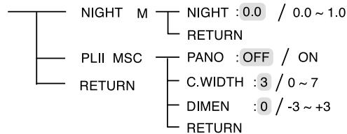
SETTING THE PARAMETER
flowchart
graph TD
    A["PARAMTR"] --> B["NIGHT M"]
    A --> C["PLII MSC"]
    A --> D["RETURN"]
    B --> E["NIGHT : 0.0 / 0.0 ~ 1.0"]
    B --> F["RETURN"]
    C --> G["PANO : OFF / ON"]
    C --> H["C.WIDTH : 3 / 0 ~ 7"]
    C --> I["DIMEN : 0 / -3 ~ +3"]
    C --> J["RETURN"]
- NIGHT M (NIGHT MODE) : To adjust the dynamic range compression that makes faint sound easier to hear at low volume levels.
- PLII MSC (DOLBY PLII MUSIC) : To adjust the various surround parameters for optimum surround effect.
- RETURN: To return to the previous menu.
When selecting the NIGHT MODE
- This function compresses the dynamic range of previously specified parts of Dolby Digital sound track (with extremely high volume) to minimize the difference in volume between the specified and non-specified parts.
This makes it easy to hear all of the sound track when watching movies at night at low levels.
Notes:
- The night mode setting is valid only when the digital signals from Dolby Digital program source are being input.
- In some Dolby Digital softwares, the night mode setting may not be valid.
- Press the CURSOR UP(▲)/DOWN(▼) buttons to select the "NIGHT M", then press the ENTER button.
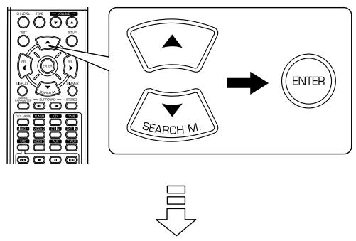
flowchart
graph TD
    A["Left Control Panel"] --> B["Search M."]
    B --> C["ENTER"]
    D["Down Arrow"] --> E["Next Step"]
NIGHT:00
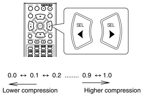
- Press the CURSOR LEFT(◀)/RIGHT(▶) buttons to adjust the dynamic range compression as desired.
text_image
0.0 ↔ 0.1 ↔ 0.2 ...... 0.9 ↔ 1.0 Lower compression Higher compressionWhen selecting the DOLBY PLII MUSIC
-
You can adjust the various surround parameters for optimum surround effect.
■ Note: The parameter settings are valid only when listening in Dolby Pro Logic II Music mode. -
Press the CURSOR UP(▲)/DOWN(▼) buttons to select the "PLII MSC", then press the ENTER button.
flowchart
graph LR
    A["Left Control Panel"] --> B["Search Button"]
    B --> C["ENTER"]
    style A fill:#f9f,stroke:#333
    style C fill:#ccf,stroke:#333

PAND: OFF
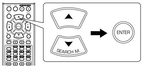
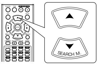
- Press the CURSOR UP(▲)/DOWN(▼) buttons to select the desired parameter.
text_image
Search M.- Press the CURSOR LEFT(◀)/RIGHT(▶) buttons to adjust the selected parameter as desired.

text_image
Diagram showing a remote control interface with two labeled 'SEL' buttons, one pointing to the left panel.■ When selecting the "PANO (Panorama)" mode This mode extends the front stereo image to include the surround speakers for an exciting "wraparound" effect with side wall imaging. Select "OFF" or "ON"(default value:OFF).
■ When selecting the "C. WIDTH (Center width)" control
This adjusts the center image so it may be heard only from the center speaker, only from the left/right speakers as a phantom image, or from all three front speakers to varying degrees. The control can be set in 8 steps from 0 to 7 (default value : 3).
■ When selecting the "DIMEN (Dimension)" control
This gradually adjusts the soundfield either towards the front or towards the rear. The control can be set in 7 steps from -3 to +3 (default value : 0).
- Repeat the above steps 2 and 3 to adjust other parameters.
Troubleshooting Guide
If a fault occurs, run through the table below before taking your receiver for repair.
If the fault persists, attempt to solve it by switching the receiver off and on again. If this fails to resolve the situation, consult your dealer. Under no circumstances should you attempt to repair the receiver yourself. This could void the warranty.
| PROBLEM | POSSIBLE CAUSE | REMEDY |
| No power | The AC input cord is disconnected.Poor connection at AC wall outlet or the outlet is inactive. | Connect the cord securely.Check the outlet using a lamp or another appliance. |
| No sound | The speaker cords are disconnected.The master volume is adjusted too low.The MUTE button on the remote control is pressed to ON.Incorrect selection of the input source.Incorrect connections between the components. | Check the speaker connections.Adjust the master volume.Press the MUTE button to cancel the muting effect.Select the desired input source correctly.Make connections correctly. |
| No sound from the surround speakers | Surround mode is switched off(stereo mode).Master volume and surround level are too low.A monaural source is used.Surround speaker setting is “N”. | Select a surround mode.Adjust master volume and surround level.Select a stereo or surround source.Select the desired surround speaker setting. |
| No sound from the center speaker | Surround mode is switched off(stereo mode).Center speaker setting is “N”.Master volume and center level are too low. | Select the desired surround.Select the desired center speaker setting.Adjust master volume and center level. |
| Stations cannot be received | No antenna is connected.The desired station frequency is not tuned in.The antenna is in wrong position. | Connect an antenna.Tune in the desired station frequency.Move the antenna and retry tuning. |
| Preset stations cannot be received | An incorrect station frequency has been memorized.The memorized stations are cleared. | Memorize the correct station frequency.Memorize the stations again. |
| Poor FM reception | No antenna is connected.The antenna is not positioned for the best reception. | Connect an antenna.Change the position of the antenna. |
| Continuous hissing noise during FM reception, especially when a stereo broadcast is received. | Weak signals. | Change the position of the antenna.Install an outdoor FM antenna. |
| Continuous or intermittent hissing noise during AM reception, especially at night. | Noise is caused by motors, fluorescent lamps or lightning, etc. | Keep the receiver away from noise sources.Install an outdoor AM antenna. |
| Remote control unit does not operate. | Batteries are not loaded or exhausted.The remote sensor is obstructed. | Replace the batteries.Remove the obstacle. |
■ AMPLIFIER SECTION
- Power output, stereo mode, 6 Ω, THD 0.7%, 40 Hz\~20 kHz | 2 × 50 W
• Total harmonic distortion, 6 Ω, 50 W, 1 kHz | 0.09 %
• Intermodulation distortion
60 Hz : 7 kHz= 4 : 1 SMPTE, 6 Ω, 50 W | 0.1 %
- Input sensitivity, 47 kΩ
Line (CD, TAPE, VIDEO) | 280 mV
• Signal to noise ratio, IHF "A" weighted
Line (CD, TAPE, VIDEO) | 92 dB
- Frequency response
Line (CD, TAPE, VIDEO), 20 Hz\~50 kHz | +0 dB, -3 dB
- Output level
TAPE/VIDEO 1 REC, 2.2 kΩ | 280 mV
- Bass/Treble control, 100 Hz/10 kHz | ±10 dB
- Surround mode, only channel driven
Front power output, 6 Ω, 1 kHz, THD 0.7 % | 70 W / 70 W
Center power output, 6 Ω, 1 kHz, THD 0.7 % | 70 W
Surround power output, 6 Ω, 1 kHz, THD 0.7 % | 70 W / 70 W
■ DIGITAL AUDIO SECTION
- Sampling frequency | 32, 44.1, 48, 96 kHz
- Digital input level
Coaxial, 75 Ω | 0.5 Vp-p
Optical, 660 nm | -15\~-21 dBm
■ FM TUNER SECTION
- Tuning frequency range | 87.5\~108 MHz
- Usable sensitivity, THD 3%, S/N 26 dB | 12.8 dBf
• 46 dB quieting sensitivity, mono/stereo | 20.2 / 45.3 dBf - Signal to noise ratio, 65 dBf, mono/stereo | 55 / 50 dB
• Total harmonic distortion, 65 dBf,1 kHz, mono/stereo | 0.5 / 1.0 % - Frequency response, 30 Hz\~12 kHz | ±3.0 dB
• Stereo separation, 1 kHz | 30 dB
• Capture ratio | 4 dB
• IF rejection ratio | 80 dB
■ AM TUNER SECTION
- Tuning frequency range | 522\~1611 kHz
• Usable sensitivity | 500 μV/m
• Signal to noise ratio | 40 dB - Selectivity | 25 dB
GENERAL
• Power supply | 230 V \~ 50 Hz
• Power consumption | 230 W
- Dimensions (W × H × D, including protruding parts) | 440 × 141 × 358.5 mm (17-3/8 × 5-1/2 × 14-1/8 inches)
• Weight (Net) | 9.5 kg (20.9 lbs)
RD-5503
SURROUND RECEIVER