R-772 - Audio Amplifier SHERWOOD - Free user manual and instructions
Find the device manual for free R-772 SHERWOOD in PDF.
User questions about R-772 SHERWOOD
0 question about this device. Answer the ones you know or ask your own.
Ask a new question about this device
Download the instructions for your Audio Amplifier in PDF format for free! Find your manual R-772 - SHERWOOD and take your electronic device back in hand. On this page are published all the documents necessary for the use of your device. R-772 by SHERWOOD.
USER MANUAL R-772 SHERWOOD
-
Read Instructions - All the safety and operating instructions should be read before the product is operated.
-
Retain instructions - The safety and operating instructions should be retained for future reference.
-
HeedWarnings - All warnings on the product and in the operating instructions should be adhered to.
-
Follow Instructions - All operating and use instructions should be followed.
-
Cleaning - Unplug this product from the wall outlet before cleaning. Do not use liquid cleaners or aerosol cleaners. Use a damp cloth for cleaning.
-
Attachments - Do not use attachments not recommended by the product manufacturer as they may cause hazards.
-
Water and Moisture - Do not use this product near water - for example, near a bath tub, wash bowl, kitchen sink, or laundry tub; in a wet basement, or near a swimming pool; and the like.
-
Accessories - Do not place this product on an unstable cart, stand, tripod, bracket, or table. The product may fall, causing serious injury to a child or adult, and serious damage to the product. Use only with a cart, stand, tripod, bracket, or table recommended by the manufacturer, or sold with the product. Any mounting of the product should follow the manufacturer's instructions, and should use a mounting accessory recommended by the manufacturer.
-
A product and cart combination should be moved with care. Quick stops, excessive force, and uneven surfaces may cause the product and cart combination to overturn.
-
Ventilation - Slots and openings in the cabinet are provided for ventilation and to ensure reliable operation of the product and to protect it from overheating, and these openings

PORTABLE CART WARNING
must not be blocked or covered. The openings should never be blocked by placing the product on a bed, sofa, rug, or other similar surface. This product should not be placed in a built-in installation such as a bookcase or rack unless proper ventilation is provided or the manufacturer's instructions have been adhered to.
-
Power Sources - This product should be operated only from the type of power source indicated on the marking label. If you are not sure of the type of power supply to your home, consult your product dealer or local power company. For products intended to operate from battery power, or other sources, refer to the operating instructions.
-
Grounding or Polarization - This product may be equipped with a polarized alternating-current line plug (a plug having one blade wider than the other). This plug will fit into the power outlet only one way. This is a safety feature. If you are unable to insert the plug fully into the outlet, try reversing the plug. If the plug should still fail to fit, contact your electrician to replace your obsolete outlet. Do not defeat the safety purpose of the polarized plug. AlternateWarnings - This product is equipped with a three-wire grounding-type plug, a plug having a third(grounding) pin. This plug will only fit into a grounding-type power outlet. This is a safety feature. If you are unable to insert the plug into the outlet, contact your electrician to replace your obsolete outlet. Do not defeat the safety purpose of the grounding-type plug.
-
Power-Cord Protection - Power-supply cords should be routed so that they are not likely to be walked on or pinched by items placed upon or against them, paying particular attention to cords at plugs, convenience receptacles, and the point where they exit from the product.
-
Outdoor Antenna Grounding - If an outside antenna or cable system is connected to the product, be sure the antenna or cable system is grounded so as to provide some protection against voltage surges and built-up static charges. Article 810 of the National Electrical Code, ANSI/NFPA 70, provides information with regard to proper grounding of the mast and supporting structure, grounding of the lead-in wire to an antenna discharge unit, size of
grounding conductors, location of antenna-discharge unit, connection to grounding electrodes, and requirements for the grounding electrode. See Figure 1.
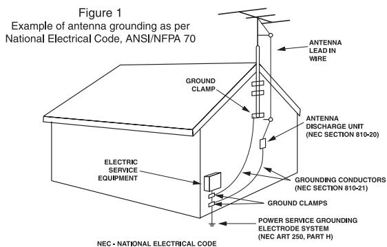
- Lightning - For added protection for this product during a lightning storm, or when it is left unattended and unused for long periods of time, unplug it from the wall outlet and disconnect the antenna or cable system. This will prevent damage to the product due to lightning and power-line surges.
- Power Lines - An outside antenna system should not be located in the vicinity of overhead power lines or other electric light or power circuits, or where it can fall into such power lines or circuits. When installing an outside antenna system, extreme care should be taken to keep from touching such power lines or circuits as contact with them might be fatal.
- Overloading - Do not overload wall outlets, extension cords, or integral convenience receptacles as this can result in a risk of fire or electric shock.
- Object and Liquid Entry - Never push objects of any kind into this product through openings as they may touch dangerous voltage points or short-out parts that could result in a fire or electric shock. Never spill liquid of any kind on the product.
- Servicing - Do not attempt to service this product yourself as opening or removing covers may expose you to dangerous voltage or other hazards. Refer all servicing to qualified service personnel.
- Damage Requiring Service - Unplug this product form the wall outlet and refer servicing to qualified service personnel under the following conditions:
a) When the power-supply cord or plug is damaged,
b) If liquid has been spilled, or objects have fallen into the product,
c) If the product has been exposed to rain or water,
d) If the product does not operate normally by following the operating instructions. Adjust only those controls that are covered by the operating instructions as an improper adjustment of other controls may result in damage and will often require extensive work by a qualified technician to restore the product to its normal operation.
e) If the product has been dropped or damaged in any way, and f) When the product exhibits a distinct change in performance - this indicates a need for service. - Replacement Parts - When replacement parts are required, be sure the service technician has used replacement parts specified by the manufacturer or have the same characteristics as the original part. Unauthorized substitutions may result in fire, electric shock, or other hazards.
- Safety Check - Upon completion of any service or repairs to this product, ask the service technician to perform safety checks to determine that the product is in proper operating condition.
- Wall or Ceiling Mounting - The product should be mounted to a wall or ceiling only as recommended by the manufacturer.
- Heat - The product should be situated away from heat sources such as radiators, heat registers, stoves, or other products (including amplifiers) that produce heat.
Introduction
READ THIS BEFORE OPERATING YOUR UNIT

CAUTION RISK OF ELECTRIC SHOCK DO NOT OPEN

CAUTION
TO REDUCE THE RISK OF ELECTRIC SHOCK,DO NOT REMOVE COVER (OR BACK).NO USER-SERVICEABLE PARTS INSIDE.REFER SERVICING TO QUALIFIED SERVICE PERSONNEL.

This symbol is intended to alert the user to the presence of uninsulated "dangerous voltage" within the product's enclosure that may be of sufficient magnitude to constitute a risk of electric shock to persons.

This symbol is intended to alert the user to the presence of important operating and maintenance (servicing) instructions in the literature accompanying the appliance.
WARNING : TO REDUCE THE RISK OF FIRE OR ELECTRIC SHOCK, DO NOT EXPOSE THIS APPLIANCE TO RAIN OR MOISTURE.
Caution regarding installation
Note : For heat dispersal, do not install this unit in a confined space such as a bookcase or similar enclosure.
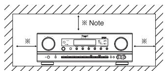
Do not block ventilation openings or stack other equipment on the top.
Note to CATV System Installer :
This reminder is provided to call the CATV system installer's attention to Article 820-40 of the NEC that provides guidelines for proper grounding and, in particular, specifies that the cable ground shall be connected to the grounding system of the building, as close to the point of cable entry as practical.
FCC INFORMATION
This equipment has been tested and found to comply with the limits for a Class B digital device, pursuant to Part 15 of the FCC Rules. These limits are designed to provide reasonable protection against harmful interference in a residential installation. This equipment generates, uses and can radiate radio frequency energy and, if not installed and used in accordance with the instructions, may cause harmful interference to radio communications. However, there is no guarantee that interference will not occur in a particular installation. If this equipment does cause harmful interference to radio or television reception, which can be determined by turning the equipment off and on, the user is encouraged to try to correct the interference by one or more of the following measures:
- Reorient or relocate the receiving antenna.
- Increase the separation between the equipment and receiver.
- Connect the equipment into an outlet on a circuit different from that to which the receiver is connected.
- Consult the dealer or an experienced radio/TV technician for help.
Caution: Any changes or modifications in construction of this device which are not expressly approved by the party responsible for compliance could void the user's authority to operate the equipment.
FOR YOUR SAFETY
| U.S.A CANADA | 120 V | Units shipped to the U.S.A and CANADA are designed for operation on 120 V AC only. Safety precaution with use of a polarized AC plug. However, some products may be supplied with a nonpolarized plug. CAUTION : To prevent electric shock, match wide blade of plug to wide slot, fully insert. ATTENTION : Pour éciter chocs électriques, introduire la lame la plus large de la fiche dans la borne correspondante de la prise et pousser jusqu' au fond. |
CAUTION
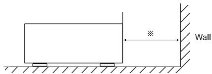
- Leave a space around the unit for sufficient ventilation.
- Avoid installation in extremely hot or cold locations, or in an area that is exposed to direct sunlight or heating equipment.
- Keep the unit free from moisture, water, and dust.
- Do not let foreign objects in the unit.
The ventilation should not be impeded by covering the ventilation openings with items, such as newspapers, table-cloths, curtains, etc. - No naked flame sources, such as lighted candles, should be placed on the unit.
- Please be care the environmental aspects of battery disposal.
- The unit shall not be exposed to dripping or splashing for use.
- No objects filled with liquids, such as vases, shall be placed on the unit.
- Do not let insecticides, benzene, and thinner come in contact with the set.
- Never disassemble or modify the unit in any way.
Notes on the AC power cord and the wall outlet.
The unit is not disconnected from the AC power source(mains) as long as it is connected to the wall outlet, even if the unit has been turned off. - When disconnecting the power cord from the wall outlet, always pull the plug, not the power cord.
- Disconnect the plug from the wall outlet when not using the unit for long periods of time.
- The wall outlet shall be installed near the unit and shall be easily accessible.
CONTENTS
SAFETYINSTRUCTIONS 2
Introduction
READ THIS BEFORE OPERATING YOUR UNIT 3
- System Connections 5
- Front Panel Controls 15
Universal Remote Controls 17
- ROOM 2 Remote Controls
REMOTE CONTROL OPERATION RANGE 29
LOADING BATTERY 29
Operations
LISTENING TO A PROGRAM SOURCE 30
SURROUND SOUND 32
ENJOYING SURROUND SOUND 34
LISTENING TO RADIO BROADCASTS 38
LISTENING TO XM SATELLITE RADIO 40
(XM Satellite Radio (only for North America))
OTHER FUNCTIONS 43
ROOM 2 SOURCE PLAYBACK 44
RECORDING 45
DIGITAL AUDIO RECORDING WITH MD REORDER 46
- OSD Menu Settings 47
SETTING THE SYSTEM SETUP 49
SETTING THE INPUT SETUP 53
SETTING THE SPEAKER / ROOM EQ SETUP 57
SETTING THE CH LEVEL SETUP 64
SETTING THE SOUND PARAMETER 66
SETTING THE MULTI ROOM SETUP 70
- Troubleshooting Guide 71
- Specifications 72
- Setup Code Table 73
System Connections
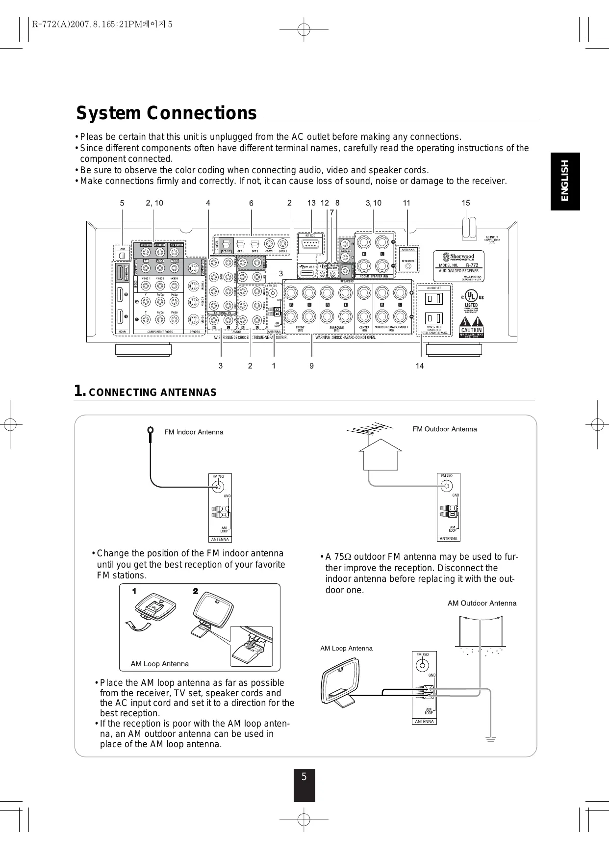
- Pleas be certain that this unit is unplugged from the AC outlet before making any connections.
- Since different components often have different terminal names, carefully read the operating instructions of the component connected.
- Be sure to observe the color coding when connecting audio, video and speaker cords.
- Make connections firmly and correctly. If not, it can cause loss of sound, noise or damage to the receiver.
1. CONNECTING ANTENNAS
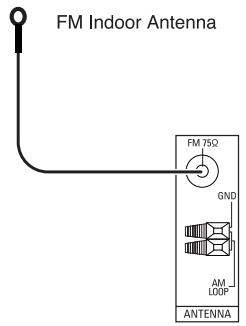
- Change the position of the FM indoor antenna until you get the best reception of your favorite FM stations.
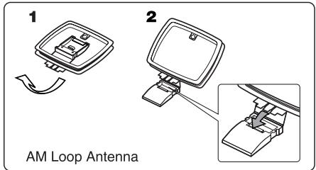
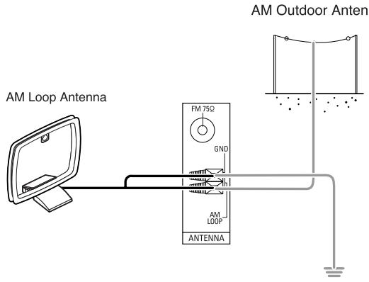
- Place the AM loop antenna as far as possible from the receiver, TV set, speaker cords and the AC input cord and set it to a direction for the best reception.
- If the reception is poor with the AM loop antenna, an AM outdoor antenna can be used in place of the AM loop antenna.
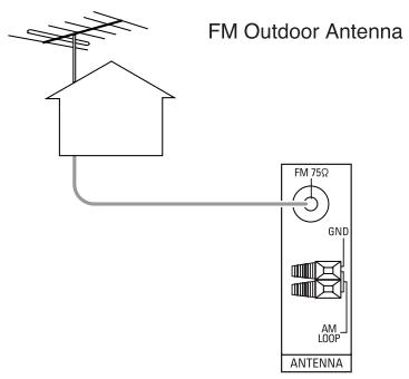
- A 75 outdoor FM antenna may be used to further improve the reception. Disconnect the indoor antenna before replacing it with the outdoor one.
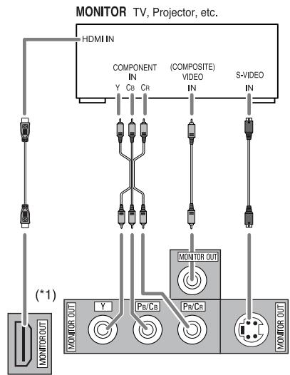
2. CONNECTINGVIDEOCOMPONENTS
- The jacks of VIDEO 1 may also be connected to a DVD recorder or other digital video recording component. For details, refer to the operating instructions of the component to be connected.
- The jacks of VIDEO 2/VIDEO 3 can also be connected to an additional video component such as a cable TV tuner or satellite system.
- Connect the jacks of VIDEO 3 to the video component in the same way.
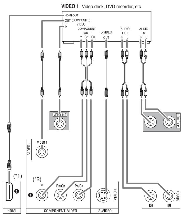
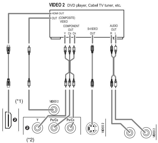
- There are three types of video jacks (COMPONENT, S-VIDEO, (composite)VIDEO) for analog video connections and the HDMI connectors for digital video and audio connections. Connect them to the corresponding video jacks according to their capability.
- For your reference, the excellence in picture quality is as follows: "HDMI" > "COMPONENT" > "S-VIDEO" > "(composite)VIDEO".
- When making COMPONENT Video connections, connect "Y" to "Y", "PB/CB" to "CB" (or "B-Y", "PB") and "PR/CR" to "CR"(or "R-Y", "PR").
- When recording video program sources through VIDEO 1 OUT jacks or viewing ROOM 2 source through ROOM 2 OUT jacks, you must use the same type of video jacks that you did connect to video playback components such as DVD player, cable TV tuner, etc.
- This unit is equipped with a function that up-converts composite video or S-Video signals to component video signals or down-converts S-Video signals to composite video signals and outputs them from the MONITOR OUTs.
Because of this, you need not connect all the types of the MONITOR OUT jacks to the MONITOR TV.
- After connecting the video components, you should set the video mode correctly, referring to the following table on page 7. (For details, refer to "When selecting the VIDEO MODE" on page 54.)
Continued
■ Relationship between the video input signal and the video output signal
| Video input signals | Video Mode Setting | MONITOR OUTs | ||||
| COMPONENT | S-VIDEO | (COMPOSITE)VIDEO | COMPONENT | S-VIDEO | (COMPOSITE)VIDEO | |
| ○ | ○ | ○ | Auto | Component | S-Video | Composite video*3 |
| Component *1 | Component | × | × | |||
| S-Video*2 | S-Video | S-Video | S-Video | |||
| Composite*2 | Composite video | Composite video | Composite video | |||
| ○ | ○ | × | Auto | Component | S-Video | S-Video |
| ○ | × | ○ | Auto | Component | Composite video | Composite video |
| ○ | × | × | Auto | Component*4 | × | × |
| × | ○ | ○ | Auto | S-Video | S-Video | Composite video*3 |
| × | ○ | × | Auto | S-Video | S-Video | S-Video |
| × | × | ○ | Auto | Composite video | Composite video | Composite video |
1 : Component video signal can be output from the COMPONENT MONITOR OUT jacks only. In this case, the OSD menu and the momentary OSD cannot be displayed.
2 : The video signal set in the VIDEO MODE menu can be output from all the types of MONITOR OUT jacks.
3 : The OSD menu and the momentary OSD cannot be displayed via (COMPOSITE) VIDEO MONITOR OUT jack.
4 : If the OSD menu operation is performed, the picture is automatically turned off and only the OSD menu is displayed via COMPONENT MONITOR OUT jacks.
■ Note :
- When outputting the component video signal from the COMPONENT MONITOR OUT jacks as it was input, the momentary OSD cannot be displayed.
■HDMI (High Definition Multimedia Interface) connection : (*1)
- You can connect the source component (DVD player, etc.) to the display component (TV, projector, etc.) through this receiver with using a commercially available HDMI cord.
- The HDMI connection can carry uncompressed digital video signals and digital audio signals.
- The HDMI video stream signals (video signals) are theoretically compatible with DVI-D. When connecting to a TV monitor, etc., equipped with DVI-D connector, it is possible to connect using a commercially available HDMI-DVI converter cord. Since the HDMI-to-DVI connection cannot carry any audio signals, you should make audio connections to play the audio signals on the component equipped with DVI-D connector. (For details, refer to the operating instructions of its.)
- If you connect the HDMI INs to your video components, it is easier to do so following the default settings.
- If your HDMI connection is different from the default setting, you should assign the HDMI INs you used with the "When selecting the HDMI ASSIGN" procedure on page 54.
- The default settings are as follows : HDMI 1 : VIDEO 1 , HDMI 2 :VIDEO 2
Copyright protection system
- This unit supports HDCP (High-bandwidth Digital Contents Protection), technology to protect copyright of digital video signals against illegal duplication. HDCP must also be supported on the components connected to this unit.
This unit is HDMI Ver. 1.3 compatible. - HDMI, the HDMI logo and High-Definition Multimedia Interface are trademarks or registered trademarks of HDMI licensing LLC.
Notes:
- For stable signal transfer, we recommend using HDMI cords that are a maximum of 5 meters in length.
- Among the components that support HDMI, some components can control other components via the HDMI connector. However, this unit cannot be controlled by another component via the HDMI connector.
- The audio signals from the HDMI connector (including the sampling frequency and bit length) may be limited by the component that is connected.
- The video signals will not be output properly if a component incompatible with HDCP is connected.
- If the resolutions of the video signals which are output from the HDMI MONITOR OUT and your monitor TV are not matched, the picture is not clear, natural or displayed. In this case, change the setting of the resolution on the source component (DVD player, etc.) to one which the monitor TV can handle. (For details, refer to the operating instructions of the source component.)
- When you want to enjoy only the picture on your TV, not the sound, you should set the HDMI AUDIO OUT to OFF not to output the digital audio signal from the HDMI MONITOR OUT of this receiver. (For details, refer to "When selecting the HDMI AUDIO OUT" on page 50.)
■ Component video input default settings: (^*2)
- If you connect the COMPONENT Video INs to your video components, it is easier to do so following the default settings.
- If your component video connections are different from the default setting, you should assign the COMPONENT VIDEO INs you used with the "When selecting the VIDEO ASSIGN" procedure on page 54.
The default settings are as follows:
COMPONENT IN 1 :VIDEO 1, COMPONENT IN 2 :VIDEO 2.
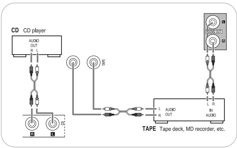
3. CONNECTING AUDIO COMPONENTS
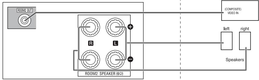
- For analog audio recording, the ROOM 2 OUT jacks can be connected to audio recording equipment such as a tape deck, an MD recorder, etc. as shown beside.
4. CONNECTING EXTERNAL INS
- Use these jacks to connect the corresponding outputs of a DVD player or external decoder, etc. that has 6, 7 or 8 channel analog audio outputs.
- In case of 6 or 7 channel outputs, do not connect both of the SURROUND BACK L and R inputs or the SURROUND BACK R input of this unit. (For details, refer to the operating instructions of the component to be connected.)
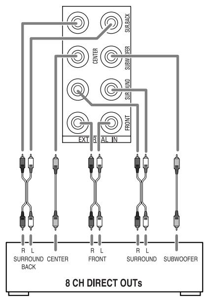
Decoder with 6, 7 or 8 channel outputs
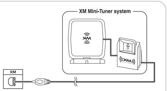
5. CONNECTING XM (only for North America)
- Connect the XM terminal to the XM Mini-Tuner system (sold separately).
- Position the XM Mini-Tuner system near a south-facing window to receive the best signal. When making connections, also refer to the operating instructions of the XM Mini-Tuner system.
- For the best reception, check the signal strength of the XM radio signal with using signal strength display mode, then adjust the position of the XM Mini-Tuner system until "GOOD" is displayed. (For details, refer to "Displaying XM information" on page 42.)
- To listen to XM Satellite Radio, refer to "XM Satellite Radio (only for North America)" on page 40.
6. CONNECTING DIGITAL INS AND OUT
- The OPTICAL and the COAXIAL DIGITAL OUTs of the components that are connected to this unit can be connected to these DIGITAL INs.
- A digital input should be connected to the components such as a CD player, DVD player, etc. capable of outputting DTS Digital Surround, Dolby Digital or PCM format digital signals, etc.
- If the component with OPTICAL IN jack is connected to the OPTICAL OUT jack of this unit, you can record the high quality sound of CDs, etc. without degradation.
- For details, refer to the operating instructions of the component connected.
- When making the COAXIAL DIGITAL connection, be sure to use a 75 COAXIAL cord, not a conventional AUDIO cord.
- All of the commercially available optical fiber cords cannot be used for the equipment. If there is an optical fiber cord which cannot be connected to your organization.
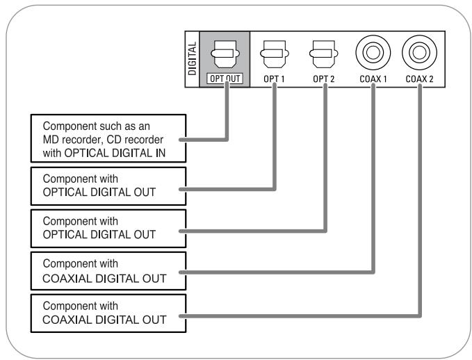
Notes:
- Be sure to make either a OPTICAL or a COAXIAL DIGITAL connection on each component. (You don't need to do both.)
- Depending on the digital audio signal format input into HDMI IN connector, some digital signals cannot be output from the OPTICAL OUT jack.
Digital input default settings
- If you connect the DIGITAL INs to your components, it is easier to do so following the default settings.
- If your DIGITAL connections are different from default settings, you should assign the DIGITAL INs you used with the "When selecting the AUDIO ASSIGN" procedure on page 54.
The default settings are as follows:
OPTICAL IN 1 :VIDEO 1, OPTICAL IN 2 :VIDEO 2, COAXIAL IN 1 : CD, COAXIAL IN 2 : AUX.
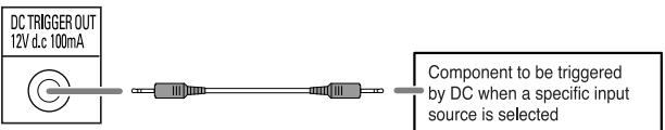
7. CONNECTING DC TRIGGER OUT
- Connect a component to DC TRIGGER OUT jack that allows DC 12V to turn on when a specific input source is selected.
- For details, refer to the operating instructions of the components to be connected.
- To link DC TRIGGER OUT with a specific input source, refer to "When selecting the DC TRIGGER" on page 55.
Notes:
- This output voltage (12V d.c., 100mA) is for (status) control only, it is not sufficient for drive capability.
- When making DC TRIGGER connection, you should use the stereo mini cord, not a mono mini cord.
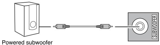
8. CONNECTING SUBWOOFER PREOUT
- To emphasize the deep bass sounds, connect a powered subwoofer.
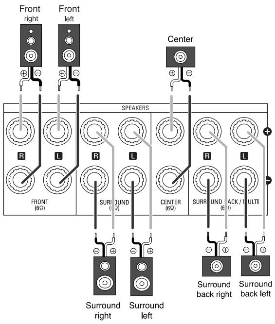
9. CONNECTING SPEAKERS
- Be sure to connect speakers firmly and correctly according to the channel(left and right) and the polarity (+ and -). If the connections are faulty, no sound will be heard from the speakers, and if the polarity of the speaker connection is incorrect, the sound will be unnatural and lack bass.
- For installing the speakers, refer to "Speaker placement" on page 11.
- After installing the speakers, first adjust the speaker settings according to your environment and speaker layout. (For details, refer to "SETTING THE SPEAKER/ROOM EQ SETUP" on page 57.)
Surround back speakers
- When using only one surround back speaker, you should connect it to SURROUND BACK/MULTI LEFT channel.
- Because this receiver cannot drive the surround back speakers and the ROOM 2 speakers simultaneously, you should assign their power amplifier correctly depending on how to use them.
(For details, refer to "CONNECTING ROOM 2 OUTS" on page 12 and "When selecting the AMP ASSIGN" on page 49.)
■ Front Bi-Amp Connections.
- Some speakers are equipped with two sets of input terminals, for bi-amplification.
- If no other surround back speakers are used, you can connect the FRONT and the SURROUND BACK/MULTI channels to the bi-amp-capable speakers. (For details, refer to the operating instructions of your bi-amp-capable speakers.)
- To drive the bi-amp-capable speakers, you should assign the power amplifier to "BI-AMP".
■ Note :
- Before making bi-amp connections, remove the short-circuiting bars from the terminals of your speakers.
Caution :
- Be sure to use the speakers with the impedance of 6 ohms or above.
- Do not let the bare speaker wires touch each other or any metal part of this unit. This could damage this unit and/or the speakers.
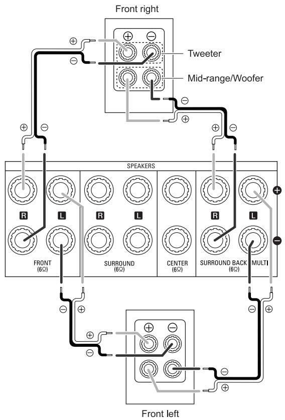
Front-Bi-Amp Connections
Speaker placement
Ideal speaker placement varies depending on the size of your room and the wall coverings, etc. The typical example of speaker placement and recommendations are as follows :
- Front left and right speakers and center speaker
- Place the front speakers with their front surfaces as flush with TV or monitor screen as possible.
- Place the center speaker between the front left and right speakers and no further from the listening position than the front speakers.
- Place each speaker so that sound is aimed at the location of the listener's ears when at the main listening position.
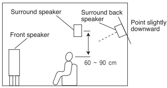
Surround left and right speakers
- Place the surround speakers approximately 1 meter (40 inches) above the ear level of a seated listener on the direct left and right of them or slightly behind.
Surround back left and right speakers
- Place the surround back speakers at the back facing the front at a narrower distance than front speakers.
- When using a single surround back speaker, place it at the rear center facing the front at a slightly higher position (0 to 20~cm ) than the surround speakers.
- We recommend installing the surround back speaker(s) at a slightly downward facing angle. This effectively prevents the surround back channel signals from reflecting off the TV or screen at the front center, resulting in interference and making the sense of movement from the front to the back less sharp.
Subwoofer
- The subwoofer reproduces powerful deep bass sounds.
Place a subwoofer anywhere in the front as desired.
Notes :
- When using a conventional TV, to avoid interference with the TV picture, use only magnetically shielded front left and right and center speakers.
- To obtain the best surround effects, the speakers except the subwoofer should be full range speakers.
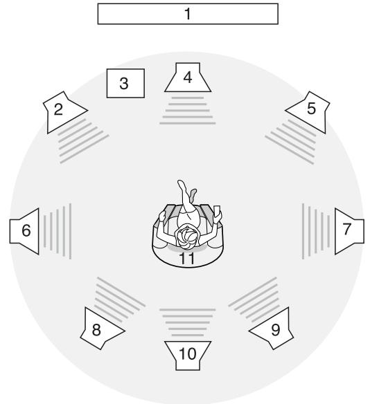
- TV or Screen
- Front left speaker
- Subwoofer
- Center speaker
- Front right speaker
-
Surround left speaker
-
Surround right speaker
- Surround back left speaker
- Surround back right speaker
- Surround center speaker
- Listening position
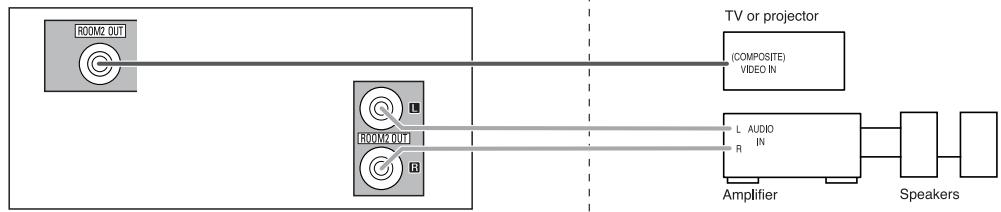
10. CONNECTING ROOM 2 OUTS
- ROOM 2 playback feature allows you to play a different program source in another room as well as one source in the main room at the same time.
- For ROOM 2 playback, connect the ROOM 2 OUT jacks to the amplifier, TV, etc. installed in another room, or connect the ROOM 2 speaker terminals to the speakers.
- Because this receiver cannot drive the surround back speakers and the ROOM 2 speakers simultaneously, you should assign their power amplifier correctly depending on how to use them. (For details, refer to "When selecting the AMP ASSIGN" on page 49.)
- When the ROOM 2 (AUDIO) OUT jacks are not connected to the ROOM 2 amplifier, you can connect these jacks to audio recording equipment such as a tape deck, an MD recorder, etc. for analog audio recording. (For details, refer to "CONNECTING AUDIO COMPONENTS" on page 8.)
Notes :
- To minimize hum or noise, use high quality connection cords.
- You cannot use the digital audio signal for ROOM 2 playback.
Main room
- When connecting ROOM 2 OUTs to the components.
This receiver
or
- When connecting ROOM 2 speaker terminals to the speakers.
This receiver
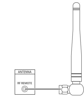
11. CONNECTING RF REMOTE ANTENNA
- Connect the supplied antenna to receive the RF (Radio Frequency) beams from the universal remote control.
- If the antenna is connected to this receiver, even though there are obstacles such as walls, furniture, etc. in the way, you can control this receiver with the universal remote control. Therefore, you can control this receiver from another room with the universal remote control without connecting the multi-room system kit. (For details, refer to "CONNECTING MULTI-ROOM SYSTEM KIT" on page 13.)
Note:
- If the walls are too thick or the distance exceeds the operation range, you cannot control this receiver with the universal remote control. In such a case, connect the multi-room system kit to this receiver and set the transmission signal mode to "IR"(Infrared). (For details, refer to "Changing the transmission signal" on page 28.)
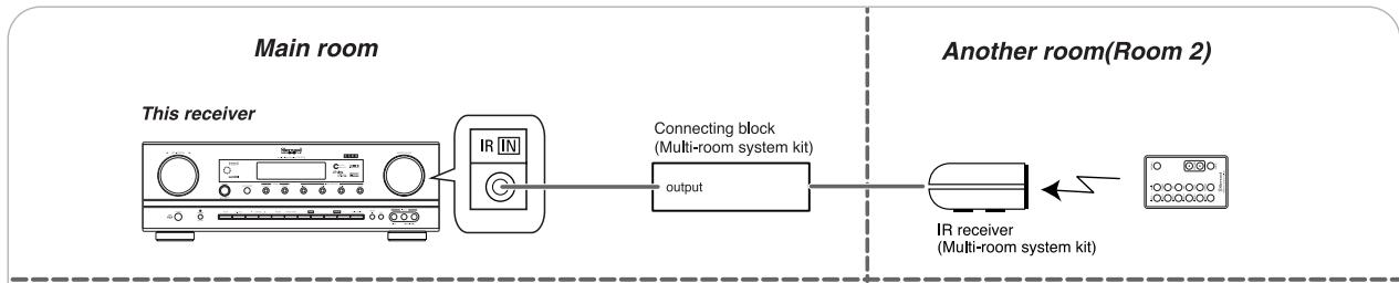
12. CONNECTING MULTI-ROOM SYSTEM KIT
- The multi-room system kit(sold separately) is essential for operation from a remote location. For information on the multi-room system kit, contact the Xantech corporation at 1-800-843-5465 or www.xantech.com.
- IR IN jack allows you to control this receiver from another room with the remote control unit.
- To control this receiver from another room with the remote control unit, connect the IR IN jack to the output of the connecting block.
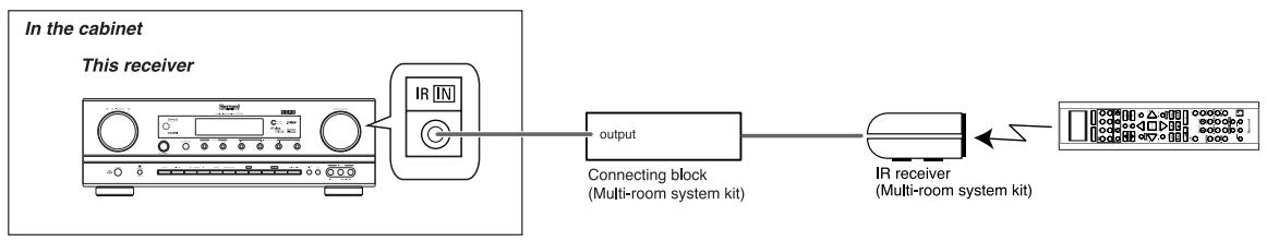
- If this receiver is located inside a cabinet or other enclosure where the signals from the remote control unit cannot enter, then operation with the remote control unit will not be possible. In such a case, connect the IR IN jack to the output of the connecting block.
Notes:
- Remote operation may become unreliable if the IR receiver is exposed to strong light such as direct sunlight or inverted fluorescent.
- When the transmission signal mode is set to "RF", the IR receiver cannot accept the RF beams from the universal remote control and remote operation will become unreliable.
- When this receiver is located inside a cabinet.
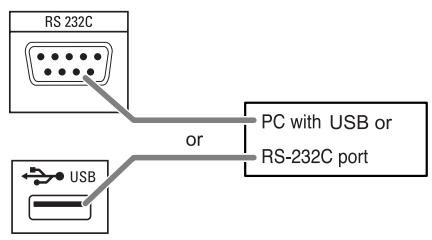
13. CONNECTING PC FOR UPGRADES
- This receiver incorporates USB as well as RS-232C terminal that may be used in the future to update the operating software so that it will be able to support new digital audio formats, external control by using an external device and the like.
- Connect either USB or RS-232C terminal to your PC (you don't need to do both).
Notes:
- Programming for upgrades and external control requires specialized programming knowledge and for that reason we recommend that it only be done by qualified installers. For more information on future upgrades and external control, visit the Sherwood web site at www.sherwoodamerica.com or contact your dealer.
- Do not disconnect the connection cable while updating the operating software, etc.
Should this happen, it may be result in malfunction or cause damage to the unit.
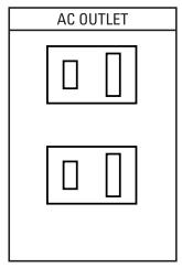
14. SWITCHED AC OUTLETS
- These outlets are switched on (power-on mode) and off (standby mode) according to power control as follows (Maximum total capacity is 120 W (1A)).
Standby mode - Switched AC outlet off Power-on mode-Switched ACoutet on
15. AC INPUT CORD
- Plug this cord into a wall AC outlet.
Front Panel Controls
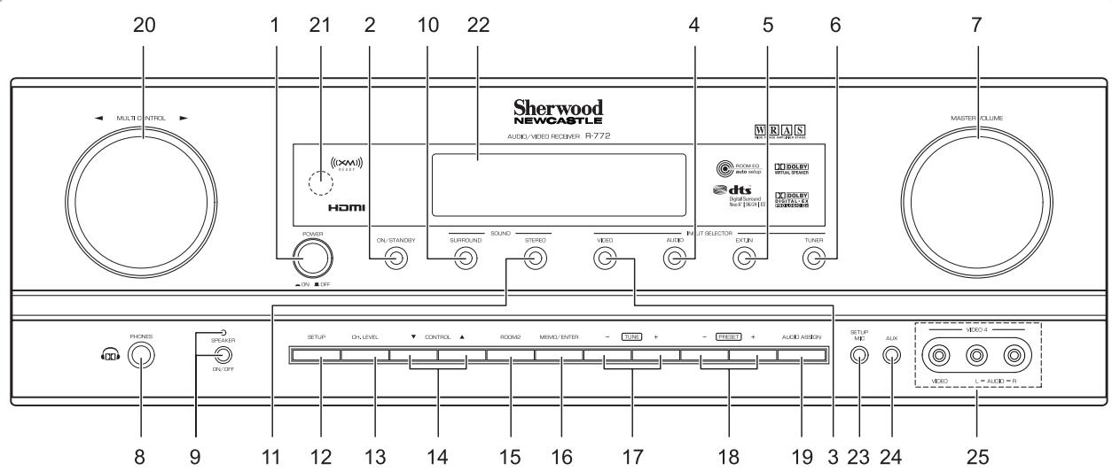
- POWER switch
- POWER ON/STANDBY button/indicator
- VIDEO INPUT SELECTOR button
- AUDIO INPUT SELECTOR button
- EXTERNAL IN button
- TUNER button
- MASTER VOLUME CONTROL knob
- HEADPHONE jack
- SPEAKER button/indicator
- SURROUND MODE button
- STEREO button
- SETUP button
- CHANNEL LEVEL button
- CONTROL UP/DOWN (/) buttons
-
ROOM 2 button
-
MEMORY/ENTER button
- TUNING UP/DOWN (+/-) buttons
- PRESET UP/DOWN (+/-) buttons
- AUDIO ASSIGN button
- MULTICONTROL knob
- REMOTE SENSOR
- FLUORESCENT DISPLAY
For details, see below.
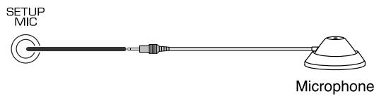
23. SETUP MIC jack
For details, see next page.
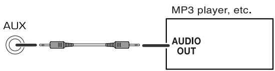
24. AUX IN jack
For details, see next page.
25. VIDEO 4 IN jackets
For details, see next page.
FLUORESCENT DISPLAY
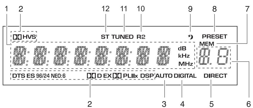
- Input, frequency, volume level, operating information, etc.
- Surround mode indicators
- AUTO indicator
- DIGITAL INPUT indicator
- DIRECT indicator
-
Preset number, sleep time display
-
MEMORY indicator
- PRESET indicator
- SLEEP indicator
- ROOM 2 indicator
- TUNED indicator
- STEREO indicator
■ SETUP MIC JACK
- To use Auto Setup function, connect the supplied microphone to the SETUP MIC jack.(For details, refer to "When selecting the AUTO SETUP" on page 57.)
Notes:
- Because the microphone for Auto Setup is designed for use with this receiver, do not use a microphone other than the one supplied with this receiver.
- After you have completed the auto setup procedure, disconnect the microphone.
AUX IN JACK
- The AUX IN jack can be connected to an additional audio component such as an MP3 player, etc.
Note:
- When connecting this jack to an MP3 player, etc., you should use the stereo mini cord, not a mono mini cord.
VIDEO 4 IN JACKS
- The VIDEO 4 IN jacks may be also connected to an additional video component such as a camcorder, a video game player, etc.
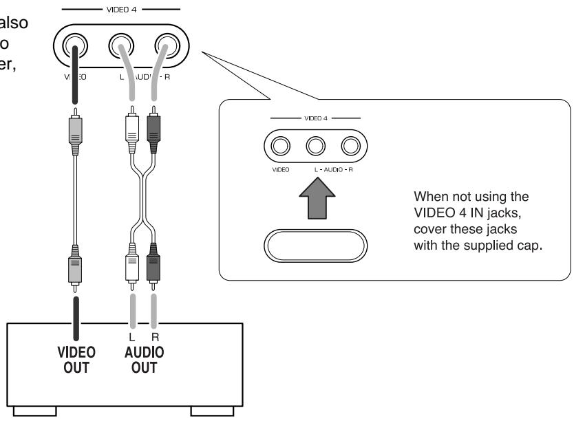
VIDEO 4 Camcorder, video game player, etc.
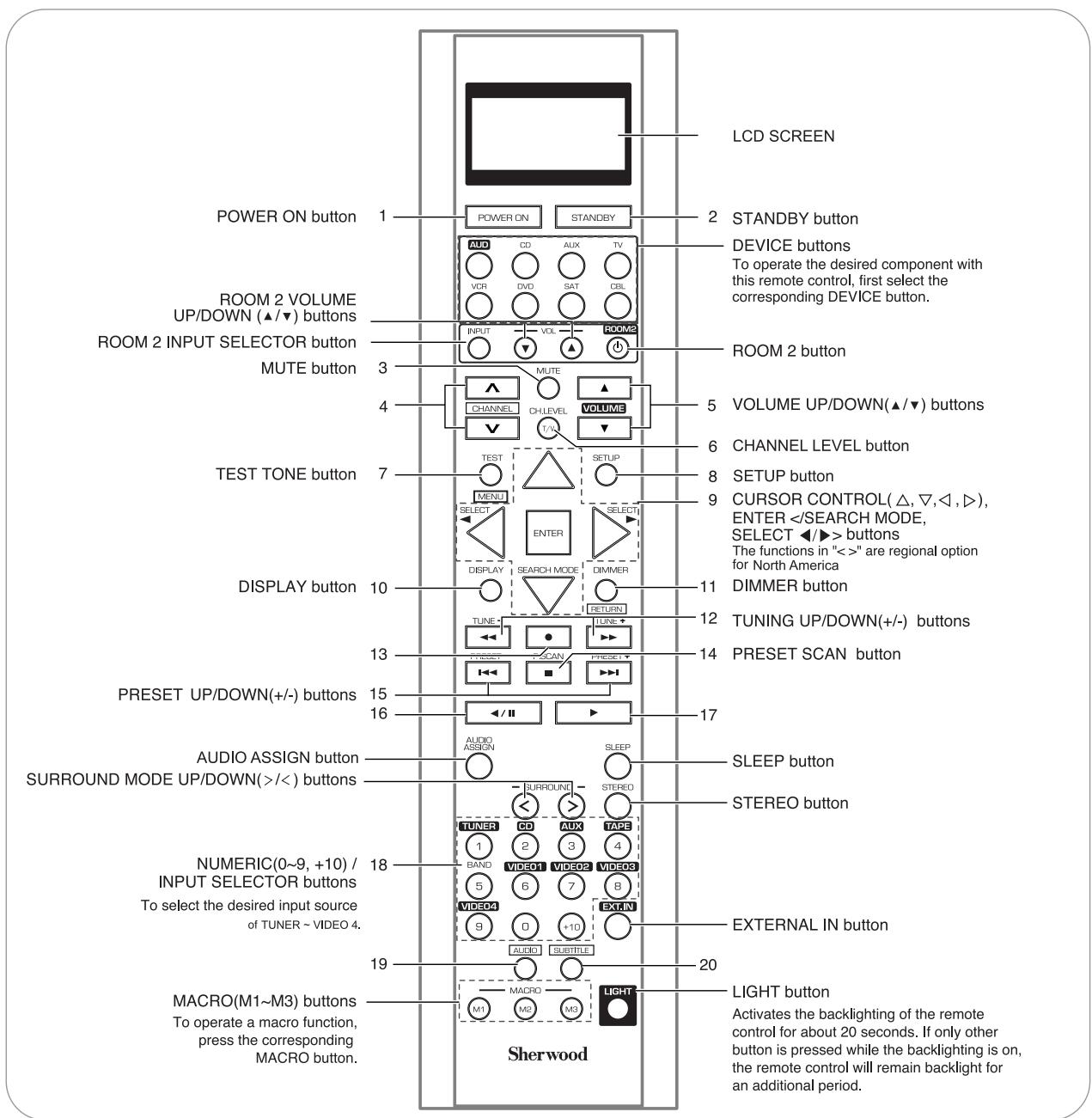
Universal Remote Controls
This universal remote control can operate not only this receiver but also most popular brands of audio and video components such as CD players, tape decks, TVs, cable boxes, VCRs, DVD players, satellite receivers, etc.
- To operate 7 components other than this receiver, you should enter the setup code for each component. (For details, refer to "USING FUNCTIONS OF REMOTE CONTROL" on page 20.)
- The numbered buttons on the remote control have different functions in different device modes. For details, refer to "FUNCTION TABLE of the NUMBERED BUTTONS" on the next page.
■ About the transmission signal
This remote control can emit not only the infrared beams which the conventional remote control(including the ROOM 2 remote control) uses but also the RF(Radio Frequency) beams which are stronger than those.
To operate this receiver and other components, this remote control should emit the infrared beams.
To operate this receiver only from longer distance even if there are obstacles such as walls, furniture, etc. in the way, this remote control should emit the RF beams.
Therefore, depending on how to use this remote control, you should set the transmission signal mode to "IR"(default value) or "RF". (For details, refer to "Changing the transmission signal" on page 28.)
Notes :
- To receive the RF beams, you should connect the RF remote antenna to this receiver. (For details, refer to "CONNECTING RF REMOTE ANTENNA" on page 12.)
- If the transmission signal mode is set to "RF", this remote control cannot control other audio and video components.
FUNCTION TABLE of the NUMBERED BUTTONS.
| Device to be controlled Button symbol | CD (for CD player) | AUX (for tape deck) | TV (for TV) | VCR (for VCR) | DVD (for DVD player) | SAT (for satellite receiver) | CBL (for cable box) | |
| 1 | POWER ON | POWER ON | POWER ON | POWER ON | POWER ON | POWER ON | POWER ON | POWER ON |
| 2 | STANDBY | STANDBY (Power OFF) | STANDBY (Power OFF) | STANDBY (Power OFF) | STANDBY (Power OFF) | STANDBY (Power OFF) | STANDBY (Power OFF) | STANDBY (Power OFF) |
| 3 | MUTE | — | — | MUTE | MUTE | — | MUTE | MUTE |
| 4 | CHANNEL | — | — | CHANNEL UP/DOWN(∧/∨) | CHANNEL UP/DOWN(∧/∨) | — | CHANNEL UP/DOWN(∧/∨) | CHANNEL UP/DOWN(∧/∨) |
| 5 | VOLUME | — | — | VOLUME UP/DOWN(▲/▼) | VOLUME UP/DOWN(▲/▼) | — | VOLUME UP/DOWN(▲/▼) | VOLUME UP/DOWN(▲/▼) |
| 6 | CH. LEVEL | — | — | INPUT SELECTOR | INPUT SELECTOR | — | INPUT SELECTOR | INPUT SELECTOR |
| 7 | TEST | — | — | — | — | MENU | — | — |
| MENU | ||||||||
| 8 | SETUP | — | — | — | — | SETUP | — | — |
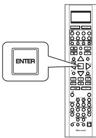
| 9 | Δ√△ | — | — | — | — | CURSOR CONTROL | — | — |
| Δ√△ | ENTER | |||||||
| 10 | DISPLAY | — | — | — | — | DISPLAY | — | — |
| 11 | DIMMER | — | — | — | — | RETURN | — | — |
| RETURN | ||||||||
| 12 | TUNE- TUNE+ | REVERSE SEARCH(↔)/ FORWARD SEARCH(↔) | REWIND(↔)/ FAST FORWARD(↔) | — | REWIND(↔)/ FAST FORWARD(↔) | REVERSE SEARCH(↔)/ FORWARD SEARCH(↔) | — | — |
| 13 | ● | — | RECORD | — | RECORD | — | — | — |
| 14 | P.SCAN | STOP | STOP | — | STOP | STOP | — | — |
| 15 | PRESET- PRESET+ | REVERSE SKIP(↔)/ FORWARD SKIP(↔) | — | — | — | REVERSE SKIP(↔)/ FORWARD SKIP(↔) | — | — |
| 16 | / / | PAUSE | REVERSE PLAY | — | PAUSE | PAUSE | — | — |
| 17 | PLAY | FORWARD PLAY | — | PLAY | PLAY | PLAY | — | — |
| 18 | NUMERIC | — | NUMERIC | NUMERIC | NUMERIC | NUMERIC | NUMERIC | NUMERIC |
| 19 | AUDIO | — | — | — | — | AUDIO | — | — |
| 20 | SUBTITLE | — | — | — | — | SUBTITLE | — | — |
Notes :
- Some functions for each component may not be available or may work differently.
- Depending on other kinds of components that are available for each DEVICE button, some functions may not be available or may work differently, too.
- For details about functions, refer to the operating instructions of each component.
OPERATING COMPONENTS WITH REMOTE CONTROL
- Enter the setup code for each component other than this receiver. For detailis, refer to "Entering a setup code" on page 20.
- Turn on the component you want to operate.
- Press the DEVICE button on the remote control corresponding to the component you wish to operate.
- Aim the remote control at the REMOTE SENSOR of the component you wish to control and press the button corresponding to the operation you want.
■ Note :
- When you cannot operate any component, check if the transmission signal mode is set to "RF". (For details, refer to "Changing the transmission signal" on page 28.)
In case that this remote control emits the infrared beams. Use the remote control within a range of about 7 meters (23 feet) and angles of up to 30 degrees aiming at the remote sensor.
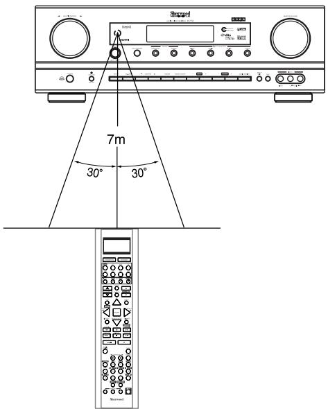
In case that this remote control emits the RF beams Use the remote control within a disatance of about 10 meters (33 feet) toward this receiver.
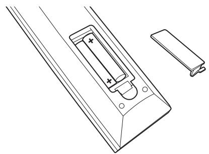
LOADING BATTERIES
- When the remote control does not operate, the old batteries should be replaced. In this case, load new batteries within several minutes after removing old batteries.
-
If the betteries are removed or have been exhausted for a longer period of time, memorized contents will be cleared. Should this happen, you should memorize them again.
-
Remove the cover.
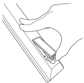
- Load four alkaline batteries ("AAA" size, 1.5V) matching the polarity.
- Remove the batteries when they are not used for a long time.
- Do not use the rechargeable batteries (Ni-Cd type).
- Be sure to use alkaline batteries.
USING FUNCTIONS OF REMOTE CONTROL
- This remote control can control up to 8 different components.
- Before operating audio and video components other than this receiver with using this remote control, the setup code for each component should be entered.
- For system remote control operation, "000" was stored previously in the memory of the device button "CD" for Sherwood CD player, "DVD" for Sherwood DVD player, "AUX" for Sherwood tape deck and "TV" for Sherwood TV respectively as its factory setup code. So, you don't need to enter its code for each Sherwood component except in such a case that its code does not work.
Note
- If the transmission signal which this remote control emits is changed into "RF"(Radio Frequency), this remote contol cannot control other audio and video components. (For details, refer to "Changing the transmission signal" on page 28.)
Entering a setup code
-
Setup code entry is the easiest way to program this remote control for operating audio and video components.
-
Turn on the component you want to operate.
- Find the setup codes according to the type and the brand name of your component, referring to "Setup Code Table" on page 73.
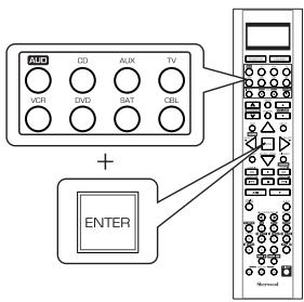
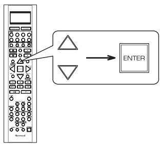
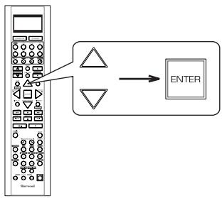
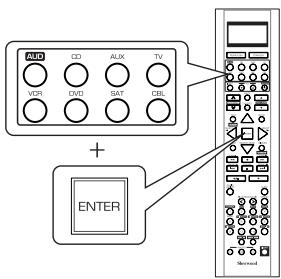
- Press and hold down both the ENTER button and the desired one of the DEVICE buttons for more than 2 seconds.
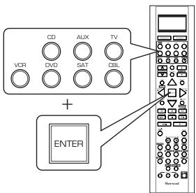
- Then "LEARN" is displayed on the LCD screen for several seconds.
Notes :
- The AUDIO button is unavailable for the audio components other than this receiver.
-
During setting operation, to exit from the setting mode, press any of the DEVICE buttons.
-
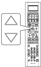
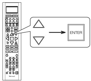
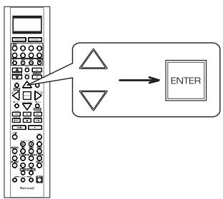
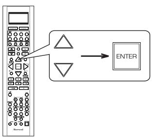
While "LEARN" is displayed, press the CURSOR UP () /DOWN () buttons to select the setup code mode ("CODE"), then press the ENTER button.
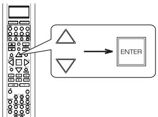
Each time the CURSOR UP(▲)/DOWN(▼) buttons are pressed, the mode changes as follows:
LEARN RF-IR DELETE MACRO CODE PUNCH
- Then "PRESET" and 3 digit number are displayed.
-
If "PRESET", etc. go off, start again from the above step 3.
-
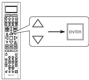
While "PRESET", etc. are displayed, enter a 3 digit code and press the ENTER button, aiming the remote sensor on the component.
Example: When entering "001".
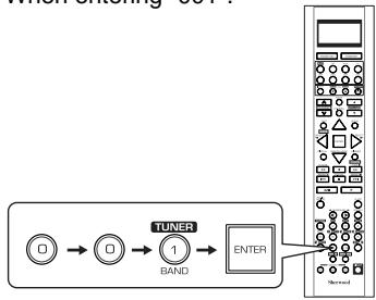
- Then "OK" is displayed on the LCD screen.
- To be sure that the setup code is correct, press the POWER ON (or STANDBY) button.
- If the setup code is correct, your component will be turned off.
- When your component is not turned off, repeat the above steps 2 to 5, trying entering each code for your component until you find one that works.
-
If "NG" is displayed, retry entering the correct setup code while "PRESET" and 3 digit number are displayed.
-
Operate the component using the corresponding function buttons.
-
If any of buttons fails to operate as they should, start from the step 1 again to enter the correct setup code.
Note: -
Manufacturers may use different setup codes for the same product category. For that reason, it is important that you check to see if the code you have entered operates as many controls as possible. If only a few functions operate, check to see if another code will work with more buttons.
-
Repeat the above steps 1 to 6 for each of your other components.
Searching a setup code
-
In addition to enter a setup code using "Setup Code Table" on page 73, it is also possible to search through all the codes that are stored in the library of this remote control.
-
Turn on the component you want to operate.
-
Perform the steps 3 and 4 in "Entering a setup code" procedure on page 20 to select the setup code mode ("CODE").
-
While "PRESET" is displayed, search a setup code, aiming the remote control at the remote sensor on the component.
Each time the CURSOR UP(▲)/DOWN(▼) buttons are pressed, the setup code is selected one by one.
- If the selected code is correct, your component will be turned off.
- When your component is not turned off, repeat this step until you find one that works.
- While "PRESET" is displayed, press the ENTER button to store the setup code.

-
Then "OK" is displayed on the LCD screen.
-
Operate the component using the corresponding function buttons.
- If any of buttons fails to operate as they should, start from the step 1 again to find the correct setup code.
- Repeat the above steps 1 to 5 for each of your other components.
Programming the commands from other remote controls (LEARNING mode)
-
If the setup codes are not available for your component or you want to program a missing or special function into one button of a device, the learning function enables this remote control to learn the commands from other remote controls.
-
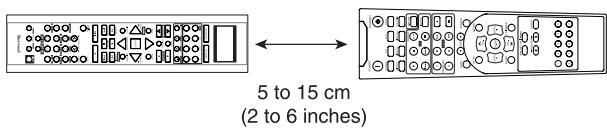
Place this remote control and other remote control facing each other at a distance of 5 to 15 cm (2 to 6 inches) apart.
- Press and hold down the ENTER button and the desired one of the DEVICE buttons for more than 2 seconds.
- Then "LEARN" is displayed on the LCD screen for several seconds
■ Note : -
During setting operation, to exit from the setting mode, press any of the DIVICE buttons.
-
While "LEARN" is displayed, press the ENTER button.
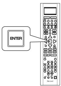
- Then "SEL" is flickering.
-
If "SEL" goes off, start again from the above step 2.
-
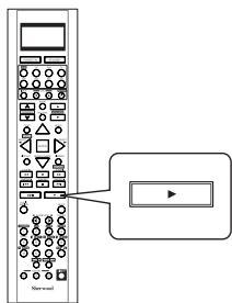
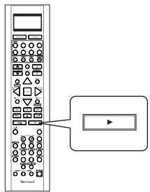
While "SEL" is flickering, on this remote control, press the button corresponding to the function to be learned.
Example: If the function to be learned is playback, press the PLAY(▶) button.
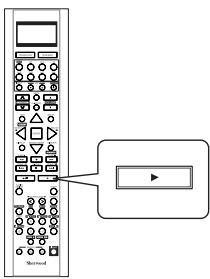
- Then "READY" is displayed.
Note:
- You cannot program a function into some buttons such as DEVICE, MACRO and LIGHT buttons.
-
While "READY" is displayed, on the other remote control, press the button of the function to be learned.
-
If the command has been learned successfully, "OK" is displayed and then "SEL" is flickering.
- If "ERROR" is displayed and then "SEL" is flickering, it means that for some reason the command was not learned. In this case, repeat the above steps 4 and 5.
Notes:
- If an incorrect signal has been sent or, in some cases, the command from other remote control simply cannot be learned.
-
In some "ERROR" cases, the remote controls just need to be moved closer together or farther apart.
-
While "SEL" is flickering, repeat the above steps 4 and 5 to program all the commands you want to the buttons on this remote control under the same device mode.
To exit from the setting mode, press any of the DEVICE buttons.
7. Repeat the above steps 1 to 6 to program the commands from a different remote control.
8. Operate the newly programmed buttons to make sure the learning function was performed properly.
Erasing the programmed command from one button
- Perform the steps 3 and 4 in "Entering a setup code" procedure on page 20 to select the deleting mode ("DELETE").
- Then "BTTN" is displayed on the LCD screen for several seconds.
- While "BTTN" is displayed, press the CURSOR UP () /DOWN () buttons to select the one command deleting mode (BTTN), then press the ENTER button.
Each time the CURSOR UP(▲)/DOWN(▼) buttons are pressed, "BTTN" or "LEARN"(all command deleting mode) is selected.
- Then "SEL" is flickering.
- If "SEL" goes off, start again from the above step 1.
- While "SEL" is flickering, press the button for the command you want to erase.
Example: When the button for the command to be erased is PLAY button.
-
"OK" is displayed and then "SEL" is flickering.
-
While "SEL" is flickering, repeat the above step 3 to erase other commands.
Erasing all the commands programmed under a device mode
- Perform the steps 3 and 4 in "Entering a setup code" procedure on page 20 to select the deleting mode ("DELETE").
- Then "BTTN" is displayed on the LCD screen for several seconds.
- While "BTTN" is displayed, press the CURSOR UP(▲)/DOWN(▼) buttons to select the all command deleting mode ("LEARN"), then press the ENTER button.
- Then "SURE?" is displayed.
-
If "SURE?" goes off, start again from the above step 1.
-
While "SURE?" is displayed, press the ENTER button.

-
Then all the commands programmed are erased.
-
To erase all the commands programmed under other device mode, repeat the above steps 1 to 3.
Programming a macro function
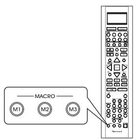
- The macro function enables you to program a series of button operations(up to 15) on this remote control into a single button.
-
You can store up to three separate macro command sequences into "M1", "M2" and "M3" buttons.
-
Perform the steps 3 and 4 in "Entering a setup code" procedure on page 20 to select the macro mode ("MACRO").
-
Then "M1" is displayed on the LCD screen for several seconds.
-
During macro setting operation, pressing any of the DEVICE buttons cannot exit from the macro mode.
-
While "M1" is displayed, press the CURSOR UP(▲)/DOWN(▼) buttons to select the MACRO button to be programmed into, then press the ENTER button.

Each time the CURSOR UP(▲)/DOWN(▼) buttons are pressed, "M1", "M2" or "M3" is selected.
- Then "SEL" is flickering.
- If "SEL" goes off, start again from the above step 1.
- While "SEL" is flickering, press the operation buttons you want to program in order.
Example: When playing a DVD on the DVD player connected to VIDEO 2 jacks of this receiver.
①. Press "AUDIO" button to control this receiver.
(2) Press "POWER ON" button to turn this receiver on.
③. Press "VIDEO 2(7)" button to select the desired input source.
④. Press "DVD" button to control the DVD player.
⑤. Press "POWER ON" button to turn the DVD player on.
⑥. Press "PLAY (▶)" button to start playback.

Each time the operation buttons are pressed, the programmed order is displayed.
- Press any of the MACRO buttons (M1~M3) to complete the programming.
- Then "OK" is displayed.
To erase a macro program
- When erasing a macro program, perform the above steps 1, 2 and 4, but ignore the step 3.
To change a macro program
- When a new macro program is stored into a MACRO button with performing the above steps 1 to 4, the previous macro program is erased from the memory of the MACRO button.
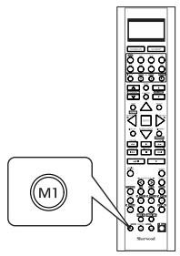
Operating a macro function
- Aim the remote control at the REMOTE SENSORs of the components to be controlled and press the MACRO button you want. Example : When pressing "M1" button.
Notes:
- The codes programmed into a MACRO button will be transmitted at an interval of 0.5 seconds. However, some components may not be able to complete one operation in 0.5 seconds and may miss the next code.
In this case, the macro function cannot control the corresponding components correctly. - Be sure to use the remote control within the remote control operation range of the components.
- Depending on the operation status of the components, etc., the macro function cannot control the corresponding components correctly.
Programming a punch-through function
- The punch-through function allows the volume controls, channel controls or transport controls to link to a different device while a device is controlled with this remote control as a master device.
-
For example, since this receiver will likely be used as the sound system while watching TV, you may want to use volume controls to operate this receiver although this remote control is set to control the TV.
-
Perform the steps 3 and 4 in "Entering a setup code" procedure on page 20 to select a master device and the punch-through mode ("PUNCH").
-
Then "VOL" is displayed on the LCD screen for several seconds.
-
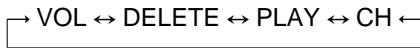
While "VOL" is displayed, press the CURSOR UP(▲)/DOWN(▼) buttons to select the desired punch-through mode, then press the ENTER button.

Each time the CURSOR UP(▲)/DOWN(▼) buttons are pressed, the mode changes as follows:
VOL: The volume punch -through mode allows the "VOLUME / " and "MUTE" buttons to operate a different device.
DELETE : All punch-through deleting mode.
↑
PLAY: The transport punch-through mode allows the "<<", "●", "▶", "I←", "■", "▶", "▲/II" and "▶" buttons to operate a different device.
CH: The channel punch-through mode allows the "CHANNEL / " and "CH. LEVEL" buttons to operate a different device.
- Then the device to which you can link the selected punch-through mode is displayed.
Continued
- While the device is displayed, press the CURSOR UP(▲)/DOWN(▼) buttons to select the desired punch-through device, then press the ENTER button.
Each time the CURSOR UP(▲)/DOWN(▼) buttons are pressed, depending on the selected punch-through mode, punch-through devices and the one punch-through deleting mode ("DELETE") are selected as follows:
In case of the volume punch-through, AUDIO DELETE TV
In case of the transport punch-through, CD DELETE DVD VCR AUX
In case of the channel punch-through, TV DELETE SAT CABLE VCR
- Then "OK" is displayed and the current punch-through mode is displayed.
- While the punch-through mode is displayed, repeat the above steps 2 and 3 to program other punch-through function under the same master device mode.
- To program punch-through functions under other master device mode, repeat the above steps 1 to 4.
Operating a punch-through function
- While this remote control is set to control a master device, aim the remote control at the REMOTE SENSOR of the punch-through device and press the desired button of the programmed punch-through controls.
Example: When pressing "PLAY () " button.
- Then the punch-through device is displayed on the LCD screen.
Erasing the programmed puch-through function
- Perform the steps 3 and 4 in "Entering a setup code" procedure on page 20 to select a master device and the punch-through mode ("PUNCH").
- Then "VOL" is displayed on the LCD screen for several seconds.
- While "VOL" is displayed, press the CURSOR UP(▲)/DOWN(▼) buttons to select the punch-through mode to be erased, then press the ENTER button.
Each time the CURSOR UP(▲)/DOWN(▼) buttons are pressed, the mode changes as follows:
VOL DELETE PLAY CH
- Then the device is displayed.
Continued
- While the device is displayed, press the CURSOR UP(▲)/DOWN(▼) buttons to select the one punch-through deleting mode ("DELETE"), then press the ENTER button.

Each time the CURSOR UP(▲)/DOWN(▼) buttons are pressed, depending on the selected punch-through mode, the punch-through devices and the deleting mode ("DELETE") are selected.
- Then "OK" is displayed and the current punch-through mode is displayed.
- While the punch-through mode is displayed, repeat the above steps 2 and 3 to erase other punch-through function under the same master device mode.
- To erase punch-through functions under other master device mode, repeat the above steps 1 to 4.
Erasing all the punch-through functions programmed under a master device mode
- Perform the steps 3 and 4 in "Entering a setup code" procedure on page 20 to select a master device and the punch-through mode ("PUNCH").
-
Then "VOL" is displayed on the LCD screen for several seconds.
-
While "VOL" is displayed, press the CURSOR UP(▲)/DOWN(▼) buttons to select the all punch-through deleting mode ("DELETE").

Each time the CURSOR UP(▲)/DOWN(▼) buttons are pressed, the mode changes as follows:
- Then "DELETE" is displayed.
3. While "DELETE" is displayed, to erase all the punch-through functions programmed under the master device mode, press ENTER button.
- Then "OK" is displayed and "DELETE" is displayed.
-
To exit from the deleting mode, press any of the DEVICE buttons.
-
To erase all the punch-through functions programmed under other master device mode, repeat the above steps 1 to 3.
Changing the transmission signal
- This remote control can emit not only the infrared beams which the conventional remote control uses but also the RF(Radio Frequency) beams which are stronger than those.
- When you want to control this receiver from longer distance even if there are obstacles such as walls, furniture, etc. in the way, change the transmission signal into "RF"(Radio Frequency).
Notes:
- When the RF remote antenna is not connected, remote operation will become unreliable. (For details, refer to "CONNECTING RF REMOTE ANTENNA" on page 12.)
-
If the transmission signal mode is set to "RF" (Radio Frequency), this remote control cannot control other audio and video components.
-
Press and hold down the ENTER button and any of the DEVICE buttons for more than 2 seconds.
Note:
- Then "LEARN" is displayed on the LCD screen for several seconds.
-
During setting operation, to exit from the setting mode, press any of the DEVICE buttons.
-
While "LEARN" is displayed, press the CURSOR UP(▲)/DOWN(▼) buttons to select the transmission signal mode("RF-IR"), then press the ENTER button.
- Then "RF" (or "IR") is displayed.
-
If "RF" (or "IR") goes off, start again from the above step 1.
-
While "RF" (or "IR") is displayed, press the CURSOR UP(▲)/DOWN(▼) buttons to select the desired transmission signal, then press the ENTER button.
Each time the CURSOR UP(▲)/DOWN(▼) buttons are pressed, the mode changes as follows:
"RF": This remote control emits the RF(Radio Frequency) beams which stronger than the infrared beams.
"IR": This remote control emits the infrared beams which the conventional remote control uses.
- Then "OK" is displayed.
■ When "RF" is set to.
- To pair up this remote control and the receiver, press the CONTROL DOWN(▼) button and the MEMORY/ENTER button simultaneously on the receiver.
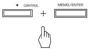
- "RF REMOCON PAIRING MODE" is displayed for several seconds on the display of the receiver.
-
If "RF REMOCON PAIRING MODE" goes off, press these buttons again.
-
While "RF REMOCON PAIRING MODE" is displayed, press the ENTER button, aiming at the receiver.
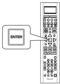
- Then "PAIRING SUCCESS" is displayed.
ROOM 2 Remote Controls
This remote control unit is an additional remote control unit for the ROOM 2 source playback only.
- You can use the ROOM 2 functions with this remote control unit more conveniently in another room than with the universal remote control unit.
- For details on ROOM 2 operation, refer to "ROOM 2 SOURCE PLAYBACK" on page 44.
- Aim the ROOM 2 remote control at the IR receiver installed in another room.(For details, refer to "CONNECTING MULTI-ROOM SYSTEM KIT" on page 13.)
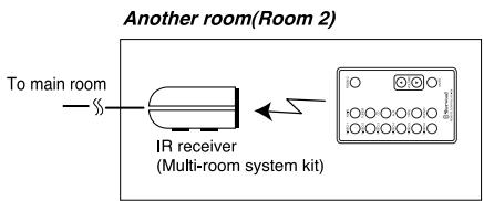
- When you operate the ROOM 2 function in the main room, aim the ROOM 2 remote control at the remote sensor of this receiver.
LOADING BATTERY
-
Remove the cover.
-
Load the battery(CR2025) matching the polarity.
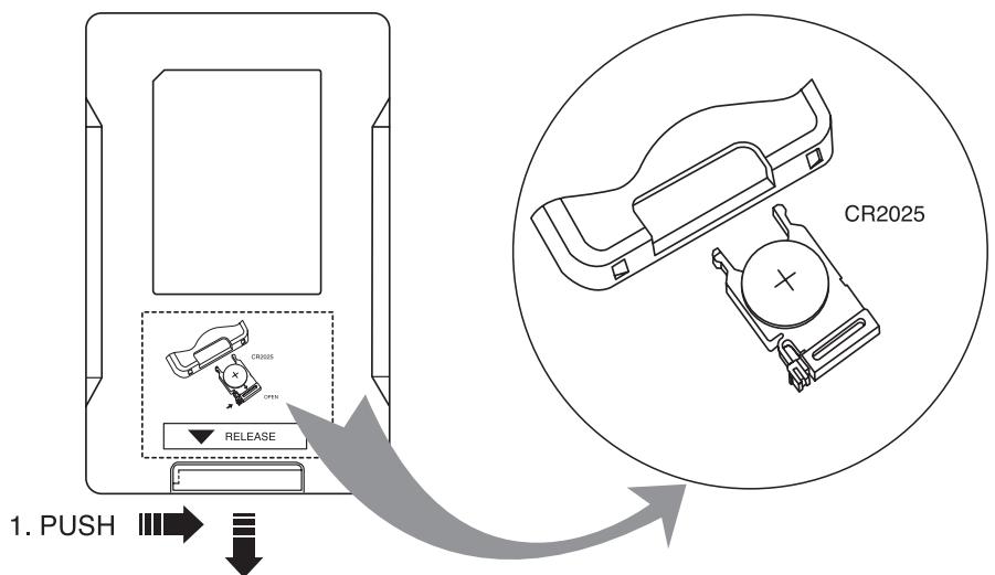
2.PULL
- Remove the battery when it is not used for a long time.
Operations
Notes:
- Before operating this receiver with the supplied remote control, refer to "Universal Remote Controls" on page 17 for details about operation.
- Before operating this receiver, first set this unit as desired for optimum performance, doing the OSD menu setting procedures. (For details, refer to "OSD Menu Settings" on page 47.)
LISTENING TO A PROGRAM SOURCE
Before operation
- Enter the standby mode.
- The POWER ON/STANDBY button lights up amber. This means that the receiver is not disconnected from the AC mains and a small amount of current is retained to support the operation readiness.
- To switch the power off, push the POWER switch again. Then the power is cut off and the POWER ON/STANDBY button goes off.

- In the standby mode, turn the power on.
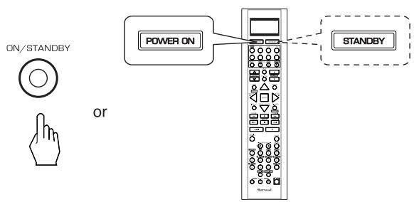
Each time the POWER ON/STANDBY button on the front panel is pressed, the receiver is turned on to enter the operating mode (the POWER ON/STANDBY button lights up blue) or off to enter the standby mode(the POWER ON/STANDBY button lights up amber).
- On the remote control, press the POWER ON button to enter the operating mode or press the STANDBY button to enter the standby mode.
- In the standby mode, if the INPUT SELECTOR button is pressed, the receiver is turned on automatically and the desired input is selected.
-
Switch the speakers on.
-
Then the SPEAKER indicator lights up and the sound can be heard from the speakers connected to the speaker terminals.
- When using the headphones for private listening, press the SPEAKER button again to switch the speakers off.

- Select the desired input source.
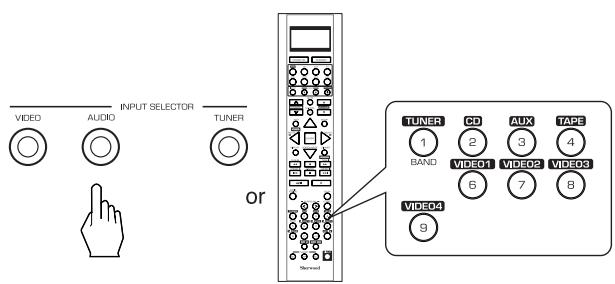
Each time the "AUDIO" button on the front panel is pressed, the input source changes as follows: CD AUX TAPE
Each time the "VIDEO" button on the front panel is pressed, the input source changes as follows: VIDEO1 VIDEO2 VIDEO3 VIDEO4
Each time the "TUNER" button is pressed, the band changes as follows: FM STereo FM MONO AM XM
■ When selecting the EXTERNAL IN as desired,
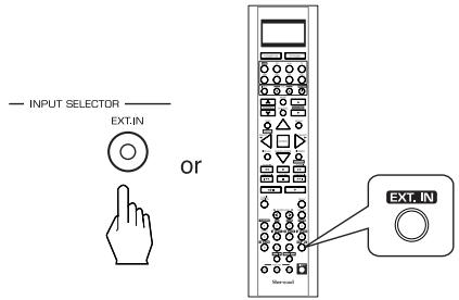
- Depending on the power amplifier setting for the surround back channels and the surround back speaker setting, "EXT. IN" is displayed and 8(/7/6) separate analog signals from the component connected to this input pass through the tone and volume circuits only and can be heard from your speakers.
- Select the desired input source to cancel the external in function.
These analog signals can be heard only, not recorded.
When CD, AUX,VIDEO 1~4 is selected as an input source
- If the AUDIO MODE is set to the mode other than "DIGITAL" for the corresponding input source on the INPUT SETUP menu, you cannot hear the sound from the selected digital input. (For details, refer to "SETTING THE INPUT SETUP" on page 53.)
4. Press the AUDIO ASSIGN button.
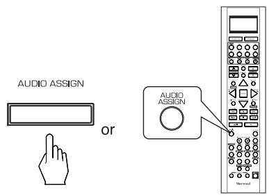
"AUD ~ " is displayed for several seconds.
"AUD \~ " disappears, press the AUDIO ASSIGN button again.
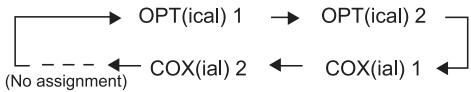
5. Select the desired of the digital inputs connected while displaying "AUD ~".

Each time the MULTI CONTOL knob is rotated on the CURSOR LEFT(▲)/RIGHT(▶) buttons are pressed, the corresponding input is selected as follows:
Notes:
- When the selected digital input is not connected or assigned, "o1", "c1", etc (, meaning no digital signal input from it) or "d"(, meaning no audio assignment) flickers and no sound will be heard.
- The selected digital input is automatically assigned to the corresponding input source on the INPUT SETUP menu. (For details, refer to "SETTING THE INPUT SETUP" on page 53.)
- The sound from the component connected to the selected digital input can be heard regardless of the selected input source.
6. Operate the selected component for playback.
- When playing back the program sources with surround sound, refer to "ENJOYING SURROUND SOUND" on page 34.
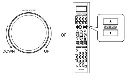
7. Adjust the (overall) volume.
Muting the sound
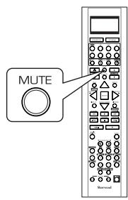
"MUTE" flickers.
- To resume the previous sound level, press it again.
Listening with headphones
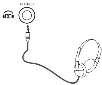
- Ensure that the SPEAKER button is set to off.
- Depending on the signal format which is being input, you can listen in Dolby Headphone mode, stereo mode, etc. (For details, refer to "Listening in Dolby Headphone mode" on page 35).
- When the EXTERNAL IN is selected as an input source, only front left and front right channel signals can be reproduced through the headphones.
Note:
- Be careful not to set the volume too high when using headphones.
SURROUND SOUND
- This receiver incorporates a sophisticated Digital Signal Processor that allows you to create optimum sound quality and sound atmosphere in your personal Home Theater.
Surround modes
DTS Digital Surround
DTS Digital Surround(also called simply DTS) is a multi-channel digital signal format which can handle higher data rates. Discs bearing the " DIGITAL" include the recording of up to
5.1 channels of digital signals, which can be generally thought to provide better sound quality due to the lower audio compression required. It also provides wide dynamic range and separation, resulting in magnificent sound.
DTS - ES Extended Surround™

This is a new multi channel digital signal format which greatly improves the 360- degree surround impression and space expression thanks to further expanded surround signals, offering high compatibility with the conventional DTS format. In addition to the 5.1 channels, DTS-ES Extended Surround also offers the surround back (sometimes also referred to as "surround center") channel for surround playback with a total of 6.1 channels. DTS-ES Extended Surround includes two signal formats with different surround signal recording methods as follows:
- DTS-ESTM Discrete 6.1
Because the signals for 6.1 channels (including the surround back channel) are fully independent, it is possible to achieve a sense that the acoustic image is moving about freely among the background sounds surrounding the listener from 360 degrees. Though maximum performance is achieved when sound tracks recorded with this system are played using a DTS -ES decoder, when played with a conventional DTS decoder, the surround back channel signals are automatically downmixed to the surround left and surround right channels so that none of the signal components are lost.
- DTS - E S^T M Matrix 6.1
With this format, the additional surround back channel signals undergo matrix encoding and are input to the surround left and surround right channels beforehand. During playback, they are decoded to the surround left, surround right and surround back channels. Because the bit stream format is 100% compatible with conventional DTS signals, the effect of the DTS-ES Matrix 6.1 format can be achieved even with DTS 5.1- channel signal sources. Of course, it is possible to play DTS-ES Matrix 6.1 - channel signal sources with a DTS 5.1 - channel decoder. When DTS-ES Discrete 6.1 or Matrix 6.1 sources are decoded with a DTS - ES decoder, the format is automatically detected upon decoding and the optimum surround mode is selected. However, some DTS - ES Matrix 6.1 sources may be detected as DTS sources. In this case, the DTS - ES Matrix mode should be selected manually to play these sources.
DTS Neo: 6^TM surround
This mode applies conventional 2-channel signals such as digital PCM or analog stereo signals to the high precision digital matrix decoder used for DTS-ES Matrix 6.1 to achieve 6.1-channel surround playback. DTS Neo : 6 surround includes two modes for selecting the optimum decoding for the signal source.
- DTS Neo : 6 Cinema
This mode is optimum for playing movies. Decoding is performed with emphasis on separation performance to achieve the same atmosphere with 2-channel sources as with 6.1-channel sources.
- DTS Neo : 6 Music
This mode is suited mainly for playing music. The front left and front right signals bypass the decoder and are played directly so there is no loss of sound quality, and the effect of the surround signals from the center, surround left, surround right and surround back channels adds a natural sense of expansion to the sound field.
DTS 96/24
Conventional surround formats used sampling frequencies of 48 or 44.1kHz , so 20kHz was about the maximum playback signal frequency. With DTS 96/24, the sampling frequency is increased to 96 or 88.2kHz to achieve a wide frequency range of over 40kHz . In addition, this format has a resolution of 24 bits, resulting in the same frequency band and dynamic range as 96kHz / 24 bit PCM signals. As with conventional DTS surround, DTS 96/24 is compatible with a maximum of 5.1 channels. DTS 96/24 is fully compatible with the conventional DTS surround format, so DTS 96/24 sources can be played using a conventional DTS 5.1 channel decoder.
"DTS" and "DTS-ES I Neo:6" are registered trademarks of DTS, Inc. "96/24" is a trademarks of DTS, Inc.
Dolby Digital
Dolby Digital is the multi-channel digital signal format developed by Dolby Laboratories. Discs bearing the
DOLBY" includes the recording of up to 5.1 channels of DIGITAL
digital signals, which can reproduce much better sound quality, spatial expansion and dynamic range characteristics than the previous Dolby Surround effect.
Dolby Digital EX
This mode creates the back (sometimes also referred to as "surround center") signals from the surround left and right signals in Dolby Digital 5.1 channel source using a matrix decoder and provides 6.1 channel surround playback. For the best results, this mode should be selected during playback of sources(bearing the "DO DOLBY") recorded in Dolby Digital DIGITALEX
EX. With this additional channel, you can experience more dynamic and realistic moving sound especially.
When Dolby Digital EX sources are decoded with a Dolby Digital EX decoder, the format is automatically detected upon decoding and the Dolby Digital EX mode is selected. However, some Dolby Digital EX sources may be detected as Dolby Digital sources. In this case, the Dolby Digital EX mode should be selected manually to play these sources.
Dolby Pro Logic IIx surround
Dolby Pro Logic IIx decodes all stereo (2 channel) and 5.1 channel sources and extends to 7.1channel surround playback. It delivers the most natural, full range and immersing 7.1 channel listening experience. Dolby Pro Logic IIx surround includes three modes as follows :
- Dolby Pro Logic IIx Movie
When enjoying movies, this mode allows you to further enhance the cinematic quality by adding processing that emphasizes the sounds of the action special effects.
- Dolby Pro Logic IIx Music
When listening to music, this mode allows you to further enhance the sound quality by adding processing that emphasizes the musical effects.
- Dolby Pro Logic IIx Game
When playing games, this mode allows you to further enhance the dynamic surround effects by adding processing that emphasizes the surrounded and exciting sound.
Dolby Pro Logic II surround
This mode applies conventional 2-channel signals such as digital PCM or analog stereo signals as well as Dolby Surround signals, etc. to surround processing to offer improvements over conventional Dolby Pro Logic circuits. Dolby Pro Logic II surround includes Dolby Pro Logic II Movie, Dolby Pro Logic II Music and Dolby Pro Logic II Game like Dolby Pro Logic Ilx surround.
■ Dolby Virtual Speaker
This mode creates a virtual surround sound field using as few as two front speakers, allowing you to experience listening from 5.1 channel speakers.
This mode is effective not only for 5.1 channel sources but also for stereo(2 channel) sources.
Dolby Virtual Speaker includes two listening mode as follows:
Dolby Virtual Speaker Reference
The width of the front sound image is defined by the actual distance between front speakers.
- Dolby Virtual Speaker Wide
The width of the front sound image seems to extend beyond the front speakers.
Dolby Headphone
The Dolby Headphone function simulates 5.1 channel surround sound, which allows you to enjoy 5.1 channel surround sound through 2 channel headphones, just like listening from 5.1 channel speakers.
This mode is effective not only for 5.1 channel sources but also for stereo (2 channel) sources.
Manufactured under license from Dolby Laboratories. "Dolby", "Pro Logic" and the double-D symbol are trademarks of Dolby Laboratories.
- The following modes apply conventional 2-channel signals such as digital PCM or analog stereo signals to high performance Digital Signal Processor to recreate sound fields artificially. Select one of the 7 provided surround modes according to the program source you want to play.
Theater
This mode provides the effect of being in a movie theater when watching a play.
Hall
This mode provides the ambience of a concert hall for classical music sources such as orchestral, chamber music or an instrumental solo.
Stadium
This mode provides the expansive sound field to achieve the true stadium effect when watching baseball or soccer games.
Room
This mode provides the sound field of a house with a low ceiling and hard walls for jazz music.
Panorama
This mode provides a dynamic and broad sound space to heighten the overall impact of the sound track.
Classic
This mode provides the acoustic effects of a large concert hall for classical music.
Multi CH Stereo
This mode is designed for playing background music. The front, surround and surround back channels create a stereo image that encompasses the entire area.
- When using the EXTERNAL INs to play back the sound from the additional multi-channel decoder for surround sound, you can enjoy the corresponding surround sound, too.(For details, refer to the operating instructions of the component to be connected.)
For your reference, the sound from each channel can be reproduced according to the surround modes as follows:
(*): Depending on the subwoofer setting, the sound from the subwoofer channel may be reproduced.
- Depending on the speaker settings and the number of the encoded channels, etc., the sound from the corresponding channels cannot be reproduced.(For details, refer to "SETTING THE SPEAKER / ROOM EQ SETUP" on page 57.)
- Before surround playback, first perform the speaker setup procedure, etc. on the OSD menu for optimum performance. (For details, refer to "SETTING THE SPEAKER/ROOM EQ SETUP" on page 57.)
- When playing digital signals from the Dolby Digital program source or selecting the surround mode such as Dolby Pro Logic II /Dolby Pro Logic IIx Music, Dolby Headphone, Dolby Virtual Speaker modes, you can adjust their parameters for optimum surround effect. (For details, refer to "SETTING THE SOUND PARAMETER" on page 66.)
- When the EXTERNAL IN is selected as an input source, the surround modes cannot be selected.
Depending on how to select a surround mode, select the auto surround mode or the manual surround mode.
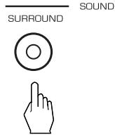
Each time this button is pressed, the mode changes as follows:
Auto surround mode : The optimum surround mode will be automatically selected depending on the signal format being input.
Manual surround mode : You can select the desired of different surround modes selectable for the signal being input with using the MULTI CONTROL knob or the SURROUND MODE UP/DOWN (> / <) buttons.
Notes :
- Even when the auto surround mode is selected and the same type of digital signal format is being input, the optimum surround mode may vary depending on whether the speaker type is set to "NO" or not.
- When the auto surround mode is selected, the surround modes other than the optimum surround mode cannot be selected.
- When selecting the manual surround mode with pressing the SURROUND MODE button on the front panel. Select the desired surround mode.
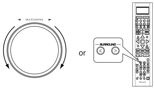
Each time the MULTI CONTROL knob is rotated or the SURROUND MODE UP / DOWN (> / <) buttons are pressed, the surround mode changes depending on the input signal format as follows:
| Signal format being input | Selectable surround mode |
| Dolby Digital EX 6.1 channel sources, Dolby Digital 5.1 channel sources | <DOLBY DIGITAL EX, DOLBY D + PLIIx MUSIC>, (DOLBY D + PLIIx MOVIE), DOLBY DIGITAL, DOLBY VS REF, DOLBY VS WIDE |
| Dolby Digital 2 channel sources | <DOLBY PLIIx MOVIE, DOLBY PLIIx MUSIC, DOLBY PLIIx GAME>, [DOLBY PLII MOVIE, DOLBY PLII MUSIC, DOLBY PLII GAME], DOLBY VS REF, DOLBY VS WIDE |
| DTS ES Discrete/Matrix 6.1 channel sources | <corresponding DTS ES mode, DTS + PLIIx MUSIC>, (DTS + PLIIx MOVIE), DTS, DOLBY VS REF, DOLBY VS WIDE |
| DTS sources, DTS 96/24 sources | corresponding DTS mode, DOLBY VS REF, DOLBY VS WIDE, <DTS + NEO:6, DTS + PLIIx MUSIC>, (DTS + PLIIx MOVIE) |
| PCM (multi-channel) sources* | MULTI PCM, <DOLBY PLIIx MOVIE, DOLBY PLIIx MUSIC>, DOLBY VS REF, DOLBY VS WIDE |
| 96 kHz PCM (2 channel) sourcesPCM (2 channel) sources, Analog stereo sources | <DOLBY PLIIx MOVIE, DOLBY PLIIx MUSIC, DOLBY PLIIx GAME>, [DOLBY PLII MOVIE, DOLBY PLII MUSIC, DOLBY PLII GAME], DOLBY VS REF, DOLBY VS WIDE, NEO:6 CINEMA, NEO:6 MUSIC, THEATER, HALL, STADIUM, ROOM, PANorama, CLASSIC, MULTI CH STEREO |
- Depending on surround back speaker setting, some surround modes can be selected or not as follows:
<>: Possible only when surround back speaker is not set to "NO".
[ ]: Possible only when surround back speaker is set to "NO".
(: Possible only when surround back speaker is set to " 2CH". - : Depending on the signal format being input, the Dolby Pro Logic IIx modes and the Dolby Virtual Speaker modes may not be selected.
Continued
■To cancel the surround mode for stereo operation
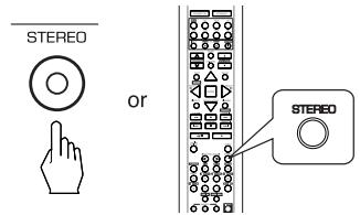
- Depending on the signal format which is being input, either the stereo mode or the 2CH downmix mode is selected.
- To cancel either the stereo mode or the 2CH downmix mode, select the surround mode with using the MULTI CONTROL knob on the front panel or the SURROUND MODE UP/DOWN (> / <) buttons on the remote control.
■2CH downmix mode
- This mode allows the multi-channel signals encoded in DTS or Dolby Digital format, etc. to be mixed down into 2 front channels and to be reproduced through only two front speakers or through headphones.
- When the SPEAKER button is set to off to listen with headphones, if the STEREO button is pressed while playing the multi-channel digital signals from DTS or Dolby Digital sources, etc., it will enter the 2CH downmix mode automatically.
- To cancel the 2CH downmix mode, select the Dolby Headphone mode with using the MULTI CONTROL knob on the front panel or the SURROUND MODE UP/DOWN ( > / < ) buttons on the remote control.
Listening in Dolby Headphone mode
- The Dolby Headphone function simulates 5.1 channel surround sound, which allows you to enjoy 5.1 channel surround sound through 2 channel headphones, just like listening from 5.1 channel speakers.
■ Note :
- Only when the SPEAKER button is set to off, the Dolby Headphone mode can be selected.
- Switch the speakers off to listen with headphones.


- Then "DOLBY HEADPHONE" (or "DOLBY H ~ ") is displayed and the Dolby Headphone mode is selected.
- To cancel the Dolby Headphone mode, press the SPEAKER button again.
Adjusting each channel level with test tone
- The volume level of each channel can be adjusted easily with the test tone function.
■ Note : When the SPEAKER button is set to off, the test tone function does not work.
1. Enter the test tone mode.
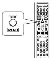
- The test tone will be heard from the speaker of each channel for 2 seconds as follows:
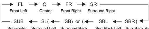
- When the speaker setting is "NO", the test tone of the corresponding channel is not available.
-
( ) : Possible depending on whether the surround back channel is set to "2 CH" or "1 CH".
-
At each channel, adjust the level as desired until the sound level of each speaker is heard to be equally loud.
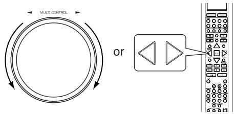
- You can select the desired channel with pressing the CONTROL UP/DOWN (/) buttons or the CURSOR UP/DOWN (/) buttons.
3. Cancel the test tone function.

Adjusting the current channel level
- After adjusting each channel level with test tone, adjust the channel levels either according to the program sources or to suit your tastes.
- You can adjust the current channel levels as desired. These adjusted levels are just memorized into user's memory ("CAL"), not into preset memory("REF 1", "REF 2").
1. Press the CHANNEL LEVEL button.
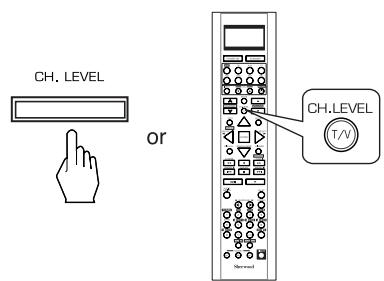
- Then the memory mode ("CAL" or "REF 1") is displayed for several seconds.
- When the memory mode or channel level disappears, press this button again.
2. Select the desired channel.
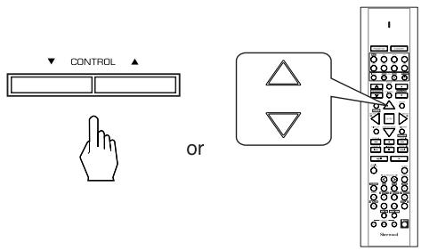
Each time these buttons are pressed, the corresponding channel is selected as follows:
REF 1(or CAL) FL C FR SR LFE SUB SL( SB) or ( SBL SBR) DTS LFE or Dolby Digital LFE
(: Possible depending on whether the surround back channel is set to "2 CH" or "1 CH".
<>: Possible only when the digital signals from Dolby Digital or DTS program sources that include LFE signal are input.
- Depending on the speaker settings("NO", etc.) and surround mode, etc., some channels cannot be selected.
- When the SPEAKER button is set to off, only the Front Left, Front Right (and LFE) channels can be selected.
3. Adjust the level of the selected channel as desired.
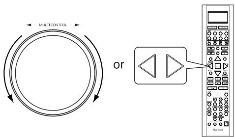
- The LFE level can be adjusted within the range of -10 0 dB and other channel levels within the range of -15 +15 dB.
- In general, we recommend the LFE level to be adjusted to 0 dB. (However, the recommended LFE level for some early DTS software is -10 dB.) If the recommended levels seem too high, lower the setting as necessary.
4. Repeat the above steps 2 and 3 to adjust each channel level.
Memorizing the adjusted channel levels
-
You can memorize the adjusted channel levels into preset memory("REF 1", "REF 2") and recall the memorized whenever you want.
-
After performing the steps 1 ~ 4 in "Adjusting the current channel level" procedure on page 36, press the (MEMORY/) ENTER button.
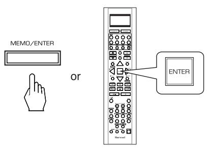
-
The "1" of "REF 1" indication flickers for several seconds.
-
Select the desired one of REF 1 and REF 2.
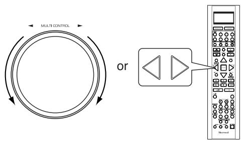
-
If the preset memory disappears, perform the above step 1 again.
-
Confirm your selection.
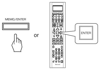
- The adjusted channel levels have now been memorized into the selected memory.
Recalling the memorized channel levels
- Press the CHANNEL LEVEL button.
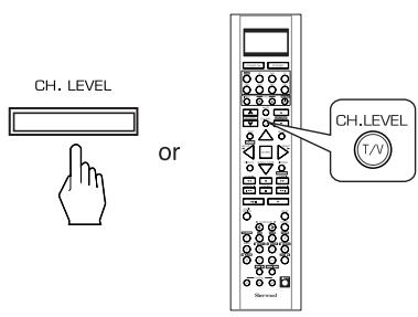
- "REF 1" (or "CAL") is displayed for several seconds.
-
If the channel level mode display disappears, press this button again.
-
Select the desired one of REF 1 and REF 2.
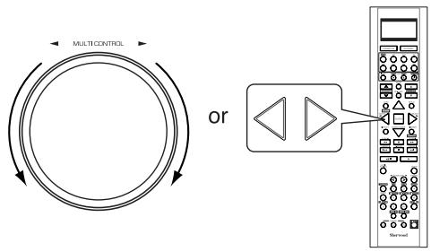
- Then the channel levels memorized into the selected preset memory are recalled.
LISTENING TO RADIO BROADCASTS
Auto tuning
1. Select the desired band.
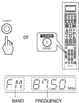
Each time this button is pressed, the band changes as follows:
FM STereo FM MONO AM XM ("ST" lights up) ("ST" goes off)
- When FM stereo broadcasts are poor because of weak broadcast signals, select the FM mono mode to reduce the noise, then FM broadcasts are reproduced in monaural sound.
- To listen to XM Satellite Radio, select XM mode. (For details, refer to "XM Satellite Radio (only for North America)" on page 40.)
2. Press the TUNING UP (+) /DOWN(-) buttons for more than 0.5 second.
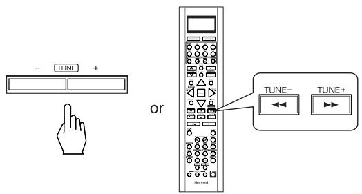
- The tuner will now search until a station of sufficient strength has been found. The display shows the tuned frequency and "TUNED".
- If the station found is not the desired one, simply repeat this operation.
- Weak stations are skipped during auto tuning.
Manual tuning
- Manual tuning is useful when you already know the frequency of the desired station.
- After selecting the desired band, press the TUNING UP (+) / DOWN(-) buttons repeatedly until the right frequency has been reached.
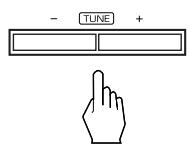
or
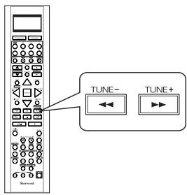
Auto presetting
- Auto presetting function automatically searches for FM stations only and store them in the memory.
While listening to FM or AM radio broadcasts, press and hold down the MEMORY/ENTER button for more than 2 seconds. - Then "AUTO MEM" flickers and this receiver starts auto presetting.
- Up to 30 FM stations can be stored.
Notes:
- FM stations of weak strength cannot be memorized.
- To memorize AM stations or weak stations, preform "Manual presetting" procedure with using "Manual tuning" operation.
Manual presetting
- You can store up to 30 preferred stations in the memory.
- Tune in the desired station with auto or manual tuning.
- Press the MEMORY/ENTER button.
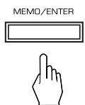
"MEM" is flickering for several seconds.
3. Select the desired preset number (1~30) and press the MEMORY/ENTER button.
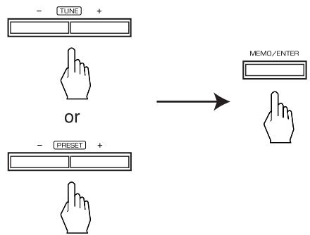
- The station has now been stored in the memory.
- A stored frequency is erased from the memory by storing another frequency in its place.
-
If "MEM" goes off, start again from the above step 2.
-
Repeat the above steps 1 to 3 to memorize other stations.
The following items, set before the receiver is turned off, are memorized.
- INPUT SELECTOR settings
- Surround mode settings
- Preset stations,etc.
Tuning to preset stations
- After selecting the tuner as an input source, select the desired preset number.
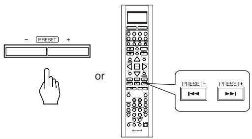
Scanning preset stations in sequence
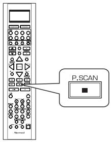
- The receiver will start scanning the stations in the preset sequence and each station is received for 5 seconds.
- At the desired station, press this button again to stop scanning.
XM Satellite Radio (only for North America)
- This receiver is the XM Ready® receiver. You can receive XM Satellite Radio® by connecting to the XM Mini-Tuner system (sold separately) and subscribing the XM service.
■About XM Satellite Radio for U.S. & Canadian products
XM Satellite Radio offers an extraordinary variety of commercial-free music, plus the best in sports, news, talk and entertainment. XM is broadcast in superior digital audio from coast to coast. From rock to reggae, from classical to hip hop, XM has something for every music fan. XM's dedication to playing the richest selection of music is matched by its passion for live sporting events, talk radio, up-to-the-minute news, stand-up comedy, children's programming, and much more. For U.S. customers, information about XM Satellite Radio is available online at www.xmradio.com. For Canadian customers, information about XM Canada is online at www.xmradio.ca.
XM Ready® legal for U.S. & Canadian products
Hardware and required monthly subscription sold separately. Other fees and taxes, including a one-time activation fee may apply. Subscription fee is consumer only. All fees and programming subject to change. Channels with frequent explicit language are indicated with an XL. Channel blocking is available for XM radio receivers by calling 1-800-XMRADIO (US residents) and 1-877-GET-XMSR (Canadian residents). For a full listing of the XM commercial-free channels and advertising-supported channels, visit lineup.xmradio.com (US residents) or xmradio.ca (Canadian residents). Subscriptions subject to Customer Agreement available at xmradio.com (US residents) and xmradio.ca (Canadian residents). Only available in the 48 contiguous United States and Canada. ©2006 XM Satellite Radio Inc. All rights reserved. All other trademarks are the property of their respective owners.
XM Ready® subscriptions for U.S. Products & Canadian products
Once you have installed the XM Mini-Tuner Dock, inserted the XM Mini-Tuner, connected the XM Dock to your XM Ready® home audio system, and installed the antenna, you are ready to subscribe and begin receiving XM programming. There are three places to find your eight character XM Radio ID: on the XM Mini-Tuner, on the XM Mini-Tuner package, and on XM Channel 0. Record the Radio ID in the following eight squares for reference.


Note: The XM Radio ID does not use the letters "I", "O", "S" or "F". Activate your XM Satellite Radio service in the U.S. online at http://activate.xmradio.com or call 1-800-XM-RADIO (1-800-967-2346). You will need a major credit card. XM will send a signal from the satellites to activate the full channel lineup. Activation normally takes 10 to 15 minutes, but during peak busy periods you may need to keep your XM Ready home audio system on for up to an hour. When you can access the full channel lineup on your XM Ready home audio system you are done. For more information or to subscribe in Canada, visit XM on the Web at www.xmradio.ca or call XM's Listener Care at 1-877-GET-XMSR (1-877-438-9677).
LISTENING TO XM SATELLITE RADIO
Signing up for XM Satellite Radio
-
Before using XM Satellite Radio, you must first sign up for an account. You will need a major credit card and your XM Satellite Radio ID, which you can get from this receiver as explained below.
-
Press the TUNER button repeatedly to select XM mode.


or
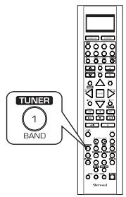
- Then "XM ~" is displayed.
- Press the TUNING UP (+) /DOWN(-) buttons repeatedly to select "XM 000".
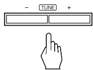
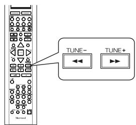
or
- Then your XM Satellite Radio ID is displayed.
-
You can find the XM Satellite Radio ID on the XM Mini-Tuner itself and the XM Mini-Tuner package. too.
-
To sign up, access the website at
"http://activate.xmradio.com" or call "1-800-967-2346".
Channel search
- In the XM mode, press the TUNING UP (+)/DOWN (-) buttons repeatedly to select the desired channel.
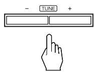
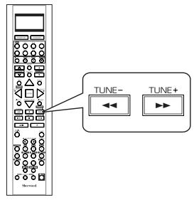
or
Direct search
- Direct search is useful when you already know the channel number.
- In the XM mode, select the direct search mode.
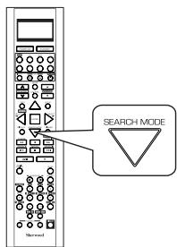
Each time this button is pressed, the search mode changes as follows:
XMCH** 串 Categoryname OFF (Direct search) (Category search)
Note:
- When using channel search or preset search, press this button to select the search off.
Category search
- Category search allows you to select the desired channel by the selected category.
- In the XM mode, select the category search mode.

-
Then a category name is displayed.
-
While displaying "XM CH * * *", select the desired channel number with pressing the NUMERIC (0 ~ 9) buttons.
Examples: For "3":

For "27":

within 4 seconds

For "124":

within 4 seconds

4 seconds ④
-
When "XM CH * * *" disappears, repeat again from the above step 1.
-
While displaying a category name, select the desired category, then press the ENTER button.
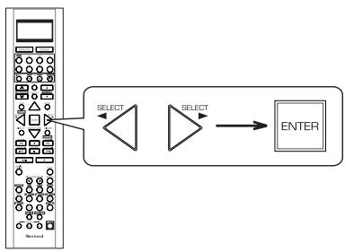
Each time these buttons are pressed, one of different categories is selected.
- When a category name disappears, repeat again from the above step 1.
Continued
- While displaying the selected category, select the desired channel.
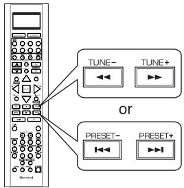
Presetting channels
- You can store up to 30 preferred channels in the memory.
- Select the desired channel with preforming channel search, direct search or category search.
- To memorize the channels, perform the steps 2 to 4 in "Manual presetting" procedure on page 39.
Preset search
- In the XM mode, select the desired preset channel.
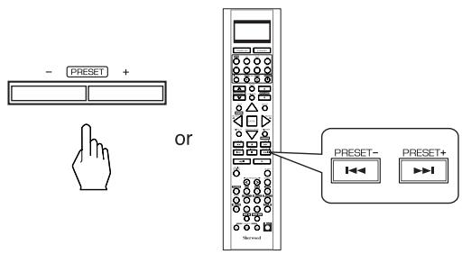
Displaying XM information
- You can display XM information such as channel name, artist name, song title and signal strength.
In the XM mode,
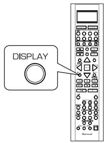
Note:
- If the information on artist name, song title or category is not available, it will not be displayed correctly.
■ Signal strength display mode
- If the reception is poor, you can check the signal strength of the XM radio signal and adjust the position of the XM antenna until "GOOD" is displayed.
Each time the DISPLAY button is pressed, the display mode changes as follows:
Channel number/name Artist name Song title Category Volume Surround mode Input signal Signal strength("GOOD", "MARGINAL", "WEAK", "NO SIGNL")
■ Error message and status
- If an operation takes longer than usual or an error occurs, one of the following messages may be displayed.
| Message | Status |
| ANTENNA | The XM antenna is not connected correctly. Check the antenna. |
| UPDATING | The XM user encryption code is being updated. Please wait. |
| NO SIGNAL | The signal is too weak. Check the antenna connection and reposition it for the best reception. |
| LOADING | This receiver is tuning or decoding audio or text data. Please wait. |
| OFF AIR | The selected XM channel is not currently broadcasting. Select another channel. |
OTHER FUNCTIONS
Operating the sleep timer
- The sleep timer allows the system to continue to operate for a specified period of time before automatically shutting off.
- To set the receiver to automatically turn off after the specified period of time.
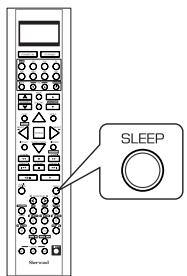
Each time this button is pressed, the sleep time changes as follows:
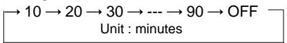
- While operating the sleep timer, "★" lights up.
Adjusting the brightness of the fluorescent display
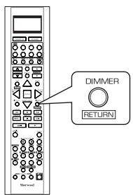
Each time this button is pressed, the brightness of the fluorescent display changes as follows:
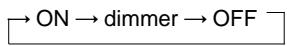
- In the display OFF mode, pressing any button will cancel the display OFF mode.
Displaying the audio information
- You can check the audio information on the input source.
- During playback,
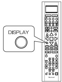
Each time this button is pressed, the display mode changes as follows:
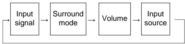
- When the EXTERNAL IN is selected as an input source, the surround mode is not displayed.
- When XM satellite radio function is available in your country, for details on the XM information, see "Displaying XM information" on page 42.
ROOM 2 SOURCE PLAYBACK
- This function allows enjoying one source in the main room and playing another in a different room at the same time.
- When you connect the multi-room system kit to the IR IN jack of this receiver, you can control this receiver with not only the universal remote control unit but also the ROOM 2 remote control unit in a different room, too. (For details, refer to "CONNECTING MULTI-ROOM SYSTEM KIT" on page 13 and "ROOM 2 Remote Controls" on page 29.)
Notes:
- The analog signals from the EXTERNAL INs and the digital signals cannot be output to the different room, meaning no playback in a different room.
-
You cannot play the ROOM 2 source in any surround mode.
-
When using the buttons on the remote control unit.
1. Press the ROOM 2 button.
- ROOM 2 ~ is displayed for several seconds.
Each time this button is pressed, the ROOM 2 mode changes as follows:
ROOM2
ROOM 2

Universal
ROOM2

OFF: To turn off the ROOM 2 function. ("R2" goes off.) ON: To turn it on. ("R2" lights up.)
■ Note :
- When the ROOM 2 mode is set to OFF, you cannot adjust the ROOM 2 volume.
2. Select the desired input as a ROOM 2 source.
Each time the INPUT button on the universal remote control unit is pressed, the ROOM 2 input can be selected among MAIN source, TUNER, CD, AUX, TAPE,VIDEO 1 ~VIDEO 4.
ROOM2
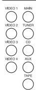
Universal
INPUT
or
3. Adjust the ROOM 2 volume.
- You can adjust the volume on the power amplifier assigned to "BACK ROOM 2" or "ROOM 2" when the ROOM 2 speaker terminals are connected to the speakers in a different room. (For details, refer to ASSIGN" on page 49.)
ROOM2
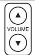
Universal
or
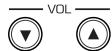
4. Start play on the component related to the ROOM 2 source.
Notes:
- When the EXTERNAL IN is selected as a main input, if the MAIN source is selected as a ROOM 2 input, no audio signal can be heard in the different room (ROOM 2).
- Even when this receiver enters the standby mode, in such a case that "R2" lights up still and the POWER ON/STANDBY button lights up blue as it does in the operating mode, meaning only the ROOM 2 circuitry operates, the ROOM 2 source can be played independently.
-
When you do not use the ROOM 2 function, turn off the ROOM 2 function to save electricity.
-
When using the buttons on the front panel.
1. Press the ROOM 2 button to enter the ROOM 2 mode.
- ROOM 2 ~ is displayed for several seconds.
- When the ROOM 2 setting mode disappears, press the ROOM 2 button again.
ROOM2


2. Select the desired mode while displaying the ROOM 2 setting mode.
Each time these buttons are pressed, the mode changes as follows:
ROOM 2 -
: To turn on or
(ROOM 2 mode)
off the ROOM 2
function.
IN ~ : To select the desired ROOM 2 source. (ROOM 2 input)
VOL ~
To adjust the volume on the power 2 volume) amplifier assigned to "BACK ROOM 2" or "ROOM 2".
Note: When the ROOM 2 mode is set to OFF, the ROOM 2 input and the ROOM 2 volume cannot be selected
3. Set the selected mode as desired.
- When selecting the ROOM 2 mode.
OFF : To turn off the ROOM 2
function. ("R2" goes off.)
ON: To turn it on. ("R2" lights up.) - When selecting the ROOM 2 input.
- You can select the desired among MAIN source, TUNER, CD, AUX,
TAPE,VIDEO1\~VIDEO4asaroom2source. - When selecting the ROOM 2 volume.
- You can adjust the volume on the power amplifier assigned to "BACK ROOM 2" or "ROOM 2" when the ROOM 2 speaker terminals are connected to the speakers in a different room. (For details, refer to "When selecting the AMP ASSIGN" on page 49.)
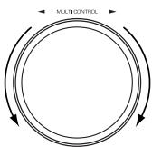
4. Start play on the component related to the ROOM 2 source.
RECORDING
- The analog signals from the EXTERNAL INs as well as the digital signals from the coaxial or optical digital input can be heard but cannot be recorded.
- When recording the analog signals from CD, AUX, VIDEO 1 ~ 4, be sure to select the "ANALOG" for the AUDIO MODE. (For details, refer to "When selecting the AUDIO MODE" on page 54.)
- The volume and tone (bass, treble) settings have no effect on the recording signals.
Recording with TAPE
-
To record the analog signals onto the recording equipment, be sure to connect the ROOM2 OUT jacks to the recording equipment. (For details, refer to "CONNECTING AUDIO COMPONENTS" on page 8.)
-
Select the desired input as a recording source except for TAPE.
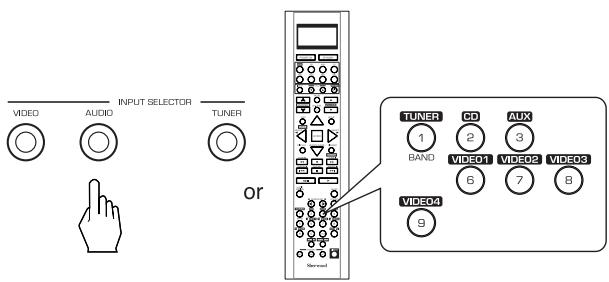
- Turn on the ROOM 2.
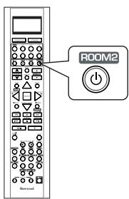
- Select the MAIN as a ROOM 2 input.
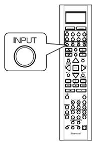
- Start recording on the TAPE.
- Start play on the desired input.
Dubbing the audio and video signals separately onto VIDEO 1
Example: When dubbing the VIDEO 2 video signal and the CD audio signal separately onto VIDEO 1.
- Select VIDEO 2 as a video recording source.
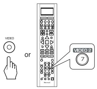
- Select CD as an audio recording source.
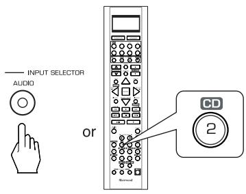
- Start recording on the VIDEO 1.
-
Start play on the VIDEO 2 and the CD respectively.
-
The audio signal from the CD and the video signal from the VIDEO 2 will be dubbed and you can enjoy them on the TV set and from the speakers.
Note: Be sure to observe the order of the above steps 1 and 2.
Dubbing from video components onto VIDEO 1
- Select the desired of VIDEO 2 ~ 4 as a recording source except VIDEO 1.
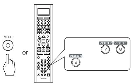
- Start recording on the VIDEO 1.
-
Start play on the desired input.
-
The audio and video signals from the desired input will be dubbed onto the VIDEO 1 and you can enjoy them on the TV set and from the speakers.
DIGITAL AUDIO RECORDING WITH MD REORDER
- Only when the OPTICAL DIGITAL OUT of this receiver is connected to the OPTICAL DIGITAL IN of the MD recorder or CD recorder, you can enjoy high-quality sound of digital recording without converting the original signals. Refer to "CONNECTING VIDEO COMPONENTS", "CONNECTING AUDIO COMPONENTS" and "CONNECTING DIGITAL INS and OUT" on pages 6~9 and the operating instructions of the MD recorder or CD recorder.
Notes:
- Depending on the digital audio signal format input into the HDMI IN connector, some digital signals cannot be output from the OPTICAL DIGITAL OUT jack.
- Digital recording is available for the digital audio program sources such as CDs, MDs, some DVDs, etc.
- In most DVDs and SACDs as well as some CDs, etc., digital recording may not be available depending on the signal format.
-
There are some restrictions on recording digital signals. When making digital recordings, refer to the operating instructions of your digital recording equipment to know what restrictions are imposed.
-
Select the desired of CD, AUX, VIDEO 1~4 as a recording source.
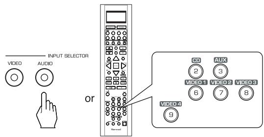
In case of recording the digital audio signal input into a HDMI IN connector
- Select the desired recording source to which the HDMI IN is connected and assigned and then perform the steps 3 and 4 (, but ignore the step 2).
■ Note :
-
If the AUDIO MODE is set to the mode other than "HDMI" for the corresponding recording source on the INPUT SETUP menu, the digital audio signals will not be output and there will be no recording. (For details, refer to "When selecting the AUDIO MODE" on page 54.)
-
For digital recording, select the digital input as recording signal input.
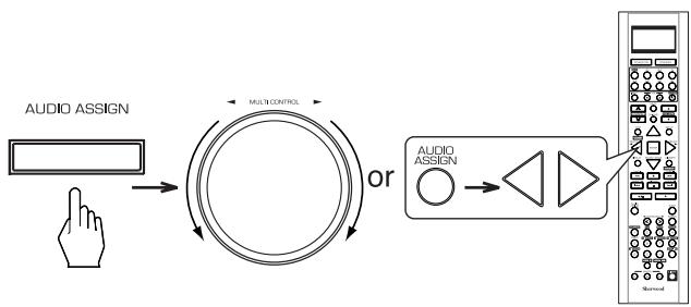
■ Note :
- If the AUDIO MODE is set to the mode other than "DIGITAL" for the corresponding recording source on the INPUT SETUP menu, the digital audio signals from the selected digital input will not be output and there will be no recording. (For details, refer to "When CD, AUX, VIDEO 1~4 is selected as an input source" on page 31 and "When selecting the AUDIO MODE" on page 54.)
- Start recording on the component connected to the OPTICAL DIGITAL OUT.
- Start play on the desired input.
OSD Menu Settings
- The OSD (On-Screen Display) menu is a setting menu that is displayed on the monitor TV and allows you to perform the setup procedures easily. In most situations, you will only need to set this once during the installation and layout of your home theater, and it rarely needs to be changed later.
The OSD menu consists of 6 main menus; system setup, input setup, speaker / room EQ setup, CH level setup, sound parameter and multi room setup. These menus are then divided up into various sub-menus.
Notes:
- The OSD menu and the momentary OSD cannot be displayed via the HDMI MONITOR OUT connector.
- Depending on the VIDEO MODE setting and the video connections between this receiver and the video component, the OSD menu and the momentary OSD cannot be displayed via (COMPOSITE)VIDEO MONITOR OUT jack, or the picture is automatically turned off and only the OSD menu can be displayed via COMPONENT MONITOR OUT jacks. (For details, refer to "Relationship between the video input signal and the video output signal" on page 7.)
Navigating through the OSD menu
- The explanations here assume you are using the buttons on the remote control when performing the OSD menu operation. However, you can use the buttons on the front panel as well.
The buttons on the front panel correspond to those on the remote control as shown below.
| Button on the remote control | SETUP | ENTER | ||
| Button on the front panel | SETUP | MEMO/ENTER | CONTROL | MULTICONTROL |
1. Turn the menu screen on.
- The main menu will be shown.
- To turn the menu screen off, press this button again.
| MAIN MENU | |
| >SYSTEM | SETUP |
| INPUT | SETUP |
| SPEAKER | |
| /ROOM EQ | SETUP |
| CH LEVEL | SETUP |
| SOUND | PARAMETER |
| MULTI ROOM | SETUP |
| EXIT | |
2. Select the desired menu using the CURSOR UP(▲)/DOWN(▼) buttons.

3. Confirm your selection.
When selecting the SYSTEM SETUP
SYSTEM SETUP
AMP ASSIGN : BACK←→ROOM2
SUBWMODE:NORMAL
HDMI AUDIO OUT : OFF
TONE CONTROL : OFF
CINEMA EQ OFF
BACKGROUND : BLACK
MOMENTARY OSD : ON
OSD POSITION ADJUST
RETURN TO MAIN MENU

When selecting the INPUT SETUP
INPUT SETUP
VIDEO 1 CONFIG
VIDEO2 CONFIG
VIDEO 3 CONFIG
VIDEO 4 CONFIG
CD CONFIG
TAPE CONFIG
AUX CONFIG
TUNER CONFIG
EXT.IN CONFIG
RETURN TO MAIN MENU
53
■When selecting the SPEAKER/ROOM EQ SETUP
SPEAKER/R.EQ SETUP
AUTO SETUP
SPEAKER CONFIG
SPEAKER DISTANCE
SPEAKER CROSSOVER
ROOM EQ SETUP
57
RETURN TO MAIN MENU
■ When selecting the CH LEVEL SETUP
CH LEVEL SETUP
MODE : CALIBRATE
FRONT LEFT 0dB
CENTER 0dB
FRONT RIGHT 0dB
SURR RIGHT 0dB
BACK/MULTI R : 0dB
BACK/MULTI L 0dB
SURR LEFT 0dB
SUBWOOFER 0dB
LFE LEVEL SETUP
RETURN TO MAIN MENU
64
When selecting the SOUND PARAMETER
SOUND PARAMETER
NIGHT MODE
DOLBY PLII MUSIC
DOLBY HEADPHONE
When selecting the MULTI ROOM SETUP
MULTI ROOM SETUP
ROOM 2 OFF
INPUT : MAIN
VOLUME
70
RETURN TO MAIN MENU
- For the setting details, see page in .
- Adjust the setting(s) in each setting category to your preference.
- When the SETUP button is pressed on a sub-menu, the menu screen will be turned off.
SETTING THE SYSTEM SETUP
SYSTEM SETUP
AMP ASSIGN : BACK←→ROOM2
SUBWMODE:NORMAL
HDMI AUDIO OUT : OFF
TONE CONTROL : OFF
CINEMA EQ OFF
BACKGROUND BLACK
MOMENTARY OSD : ON
OSD POSITION ADJUST
RETURN TO MAIN MENU
- AMP ASSIGN : To assign the surround back channels' power amplifier correctly depending on how to use the speakers.
- SUBWOOFER MODE : To select the desired subwoofer mode.
- HDMI AUDIO OUT: To output the digital audio signals from the HDMI MONITOR OUT connector.
- TONE CONTROL: To adjust the tone (bass and treble) as desired.
CINEMA EQ : To select the desired cinema EQ mode. - BACKGROUND: To select the desired background color of the momentary OSD and the OSD menu.
- MOMENTARY OSD : To turn on or off the OSD that shows the status corresponding to each operation momentarily.
- OSD POSITION ADJUST: To adjust the positon of the momentary OSD and the OSD menu.
When selecting the items other than OSD POSITION ADJUST
- Press the CURSOR UP(▲)/DOWN(▼) buttons to select the desired item.

- Press the CURSOR LEFT(▲)/RIGHT(▲) buttons to set the selected item as desired.
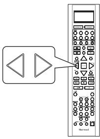
When selecting the AMP ASSIGN
- The surround back channels' power amplifier can drive the surround back speakers, the ROOM 2 speakers or the front bi-amp capable speakers. Depending on how to use the speakers, you should assign the power amplifier correctly. (For details, refer to "CONNECTING SPEAKERS" on page 10 and "CONNECTING ROOM 2 OUTS" on page 12.)
BACK ROOM 2: When connecting this receiver to the surround back speakers and the ROOM 2 speakers both, the power amplifier automatically drives the surround back speakers or the ROOM 2 speakers depending on whether the ROOM 2 function is turned off or on.
BI-AMP:To drive the front bi-amp capable speakers when connecting the FRONT and the SURROUND BACK/MULTI channels to them.
SURR BACK: To drive the surround back speakers when connecting the SURROUND BACK/MULTI channels to them.
ROOM 2 : To drive the ROOM 2 speakers when connecting the ROOM 2 channels to them.
Continued
When selecting the SUBWOOFER MODE
- "SW PLUS +" mode is valid only when "FRONT" and "CENTER" are set to "FULL RANGE" and "SUBWOOFER" is set to "YES" on the SPEAKER/ROOM EQ SETUP menu. (For details, refer to "SETTING THE SPEAKER/ ROOM EQ SETUP" on page 57.)
NORMAL : When the low frequency signals of channels set to "FULL RANGE" are reproduced from those channels only. In this mode, the low frequency signals that are reproduced from the subwoofer channel is only the low frequency signals of LFE (from the multi-channel sources that contains LFE (Low Frequency Effects) channel, also called the ".1" channel) and the channels set to the setting value other than "FULL RANGE".
SW PLUS + : When the low frequency signals of channels set to "FULL RANGE" are reproduced simultaneously from those channels and the subwoofer channel. In this mode, the low frequency range expands more uniformly through the room, but depending on the size and shape of the room, interference may result in a decrease of the actual volume of the low frequency range.
When selecting the HDMI AUDIO OUT
- The HDMI connection can carry uncompressed digital video signals and digital audio signals.
Depending on whether these digital audio signals are output from the HDMI MONITOR OUT of this receiver or not, you should set the HDMI AUDIO OUT correctly.
OFF: Not to output the digital audio signals from the HDMI MONITOR OUT of this receiver, meaning these signals are heard from the speakers connected to this receiver.
ON : To output the digital audio signals, meaning these signals are heard from the speakers of your TV.
Notes:
- When the HDMI AUDIO OUT is set to ON, no sound will be heard from the speakers connected to this receiver (except ROOM 2 speakers) even though any input source is selected.
- If your TV cannot support some digital audio formats, no sound may be heard from its speakers even when the HDMI AUDIO OUT is set to ON.
When selecting the TONE CONTROL
OFF: To listen to a program source without the tone effect. ("DIRECT" indicator lights up.)
ON: To adjust the tone for your taste. ("DIRECT" indicator goes off.)
- When the TONE CONTROL is set to ON to adjust the tone (bass and treble)
①. Press the ENTER button to enter the tone adjustment mode.
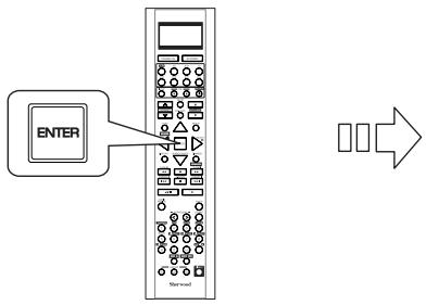
TONE CONTROL
②. Press the CURSOR UP(▲)/DOWN(▼) buttons to select the desired tone mode.
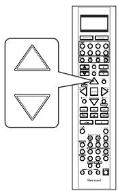
③. Press the CURSOR LEFT(▲)/RIGHT(▶) buttons to adjust the selected tone as desired.
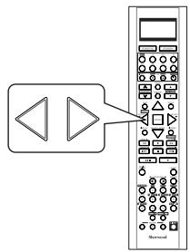
- The tone level can be adjusted within the range of -10 +10 dB.
- In general, we recommend the bass and treble to be adjusted to 0 dB (flat level).
- Extreme settings at high volume may damage your speakers.
- To complete tone adjustment, repeat the above steps ② and ③.
When selecting the CINEMA EQ
OFF: To turn off the cinema EQ function.
↑
ON : To compensate for edgy or shrill movie sound tracks.
When selecting the BACKGROUND
BLACK : To display the black as the color background of the momentary OSD and the OSD menu.
↑
BLUE : To display the blue.
■ Note : Only when no video signals are input into this unit, the selected background color will be displayed.
When selecting the MOMENTARY OSD
ON : To turn on the OSD function that shows the status corresponding to each operation on this unit
momentarily.
OFF: To turn it off.
■ Note : When outputting the component video signal from the COMPONENT MONITOR OUT jacks as it was input, the momentary OSD cannot be displayed.
When selecting the OSD POSITION ADJUST
-
You can adjust the position of the momentary OSD and the OSD menu that are displayed on the monitor TV.
-
Press the CURSOR UP(▲)/DOWN(▼) buttons to select the OSD POSITION ADJUST, then press the ENTER button.
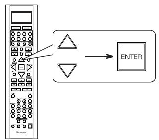

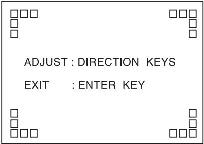
- Press the CURSOR UP(▲)/DOWN(▼)/LEFT(▲)/RIGHT(▶) buttons to adjust the position of the momentary OSD and the OSD menu as desired.
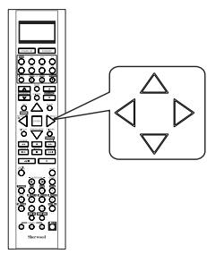
SETTING THE INPUT SETUP
INPUT SETUP
VIDEO 1 CONFIG
VIDEO 2 CONFIG
VIDEO 3 CONFIG
VIDEO 4 CONFIG
CD CONFIG
TAPE CONFIG
AUX CONFIG
TUNER CONFIG
EXT.IN CONFIG
RETURN TO MAIN MENU
- This menu allows you to make the various settings depending on how to use the input sources connected to this receiver.
When selecting the items other than NAME
- Press the CURSOR UP(▲)/DOWN(▼) buttons to select the desired input source, then press the ENTER button.
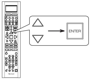

Example: When selecting the VIDEO 1
VIDEO 1 CONFIG
NAME :VIDEO 1
HDMI ASSIGN : HDMI 1
VIDEO ASSIGN : COMP 1
VIDEO MODE : AUTO
AUDIO ASSIGN : OPT 1
AUDIO MODE : AUTO

Page 1
■ When selecting the menu of page 2 or page 1.
- Press the CURSOR UP(▲)/DOWN(▼) buttons to select "GO TO NEXT ~", then press the ENTER button.
AUTO SURROUND : OFF
AUD REMASTER OFF
AVSYNC. 0ms
DC TRIGGER OFF
Page 2
- Press the CURSOR UP(▲)/DOWN(▼) buttons to select the desired item.
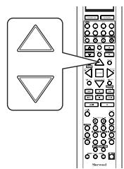
Note :
-
Depending on the input source, some items other than DC TRIGGER cannot be selected.
-
Press the CURSOR LEFT(▲)/RIGHT(▶) buttons to set the selected item as desired.
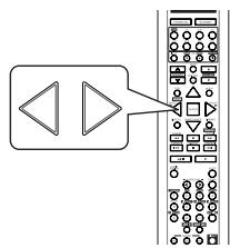
Continued
When selecting the HDMI ASSIGN
- You should assign the connected HDMI INs to the desired of VIDEO 1 ~ VIDEO 4. (For details, refer to "CONNECTING VIDEO COMPONENTS" on pages 6 ~ 7.)
- You can select HDMI 1 or HDMI 2.
Note :
- In such a case that a HDMI IN is assigned to two input sources or more, when these input sources are selected, the uncompressed digital video signals (and digital audio signals when the HDMI AUDIO OUT is set to ON) input into the same HDMI IN can be output from the HDMI MONITOR OUT of this receiver.
When selecting the VIDEO ASSIGN
- You should assign the connected COMPONENT Video INs to the desired of VIDEO 1 ~ 4. (For details, refer to "CONNECTING VIDEO COMPONENTS" on pages 6 ~ 7.)
- You can select the desired of COMP 1~2.
Note :
- In such a case that a COMPONENT Video IN is assigned to two input sources or more, when these input sources are selected, the component video signals can be viewed from the same COMPONENT Video IN.
When selecting the VIDEO MODE
- You can select the video input signal to be output from the MONITOR OUTs.
AUTO: When there are multiple video input signals, the video input signals are detected and the video input signal to be output from the MONITOR OUTs is selected automatically in the following order : component video, S-video, composite video.
COMPOSITE : The signal that is input into the (COMPOSITE) VIDEO jack is always played. The composite video input signal is up-converted and output from the S-VIDEO and COMPONENT MONITOR OUT jacks.
S-VIDEO : The signal that is input into the S-VIDEO jack is always played. The S-Video input signal is converted and output from the (COMPOSITE) VIDEO and COMPONENT MONITOR OUT jacks.
COMPONENT : The signals that are input into the COMPONENT jacks are always played.
Because video conversion is not performed, no video signals are output from the MONITOR OUT jacks when there are no video signals that are input into the COMPONENT jacks.
- For details, refer to "Relationship between the video input signal and the video output signal" on page 7.
Note : - When selecting the VIDEO 4, S-VIDEO cannot be selected.
When selecting the AUDIO ASSIGN
- You should assign the connected DIGITAL INs to the desired of CD, AUX and VIDEO 1 ~ VIDEO 4. (For details, refer to "CONNECTING DIGITAL INS AND OUT" on page 9.)
- You can select the desired of OPT 1, OPT 2, COAX1 and COAX 2.
Note:
- In such a case that a DIGITAL IN is assigned to two input sources or more, when these input sources are selected, the digital audio signals can be heard from the same DIGITAL IN.
When selecting the AUDIO MODE
- You can select the desired audio input signal to be played.
Notes: - Be sure to set the AUDIO MODE to the audio input which is connected and assigned to the selected input source.
- When the HDMI AUDIO OUT is set to ON, no sound will be heard from the speakers connected to this receiver (except ROOM 2 speakers).
- When the AUDIO MODE is set to HDMI, you should set the HDMI ASSIGN correctly. If not, "H1", "H2" (, meaning no digital audio signal input from it) or "Hd" (, meaning no HDMI assignment) flickers on the unit's display and no sound will be heard.
- When the AUDIO MODE is set to DIGITAL, you should set the AUDIO ASSIGN correctly. If not, "o1", "c1", etc., (meaning no digital signal input from it) or "d" (meaning no audio assignment) flickers on the unit's display and no sound will be heard.
AUTO : When there are multiple audio input signals, the audio input signals are detected and the audio input signal to be played
↑
is selected automatically in the priority order of them :HDMI audio > DIGITAL audio > ANALOG audio
HDMI : The signal that is input into the HDMI IN is always played.
DIGITAL : The signal that is input into the OPTICAL or the COAXIAL DIGITAL IN is always played.
ANALOG : The signal that is input into the analog AUDIO INs is always played.
Continued
When selecting the AUTO SURROUND
- Depending on how to select a surround mode, you can select the auto surround mode or the manual surround mode.
ON : The optimum surround mode will be automatically selected depending on the signal (Auto surround mode) format being input.
↑
OFF
Manual surround mode)
: You can select the desired of different surround modes selectable for the signal being input with using the MULTI CONTROL knob or the SURROUND MODE UP/DOWN ( > / < ) buttons. (For details, refer to "When selecting the manual surround mode with pressing the SURROUND MODE button on the front panel" on page 34.)
Notes :
- Even when the auto surround mode is selected and the same type of digital signal format is being input, the optimum surround mode may vary depending on whether the speaker type is set to "NO" or not.
- When the auto surround mode is selected, the surround modes other than the optimum surround mode cannot be selected.
When selecting the AUDIO REMASTER
- The remastering processes the input signal digitally and converts its digital sampling frequency to twice the current frequency (88.2/96 kHz) for a more detailed sound reproduction.
ON: To process the input signal digitally and to convert its sampling frequency to 88.2/96 kHz for a more detailed sound reproduction.
OFF: To turn off the remastering function.
Note:
- The remastering function have no effect on the input digital signal from the 88.2/96 kHz source or higher as well as the digital signal that is output from the OPTICAL DIGITAL OUT of this receiver.
When selecting the AV SYNC
- There may be a slight time delay between the video and audio signals in case that some video playback equipments may process the video signals later than the audio signals due to signal processing procedure, etc.. Should this happen, you can adjust the time delay of audio signals to synchronize the sound with the picture.
- The time delay can be adjusted within the range of 0 ~ 200 msec.
When selecting the DC TRIGGER
- To turn on the component connected to the DC TRIGGER OUT jack when this input source is selected, you should set the DC TRIGGER to ON for this input source.
OFF : To turn off the DC trigger function.
↓
ON: To turn it on.
- For details, refer to "CONNECTING DC TRIGGER OUT" on page 9.
When selecting the NAME
- You can give names to the input sources other than tuner.
-
Up to 7 characters can be entered for each name.
-
Press the CURSOR UP(▲)/DOWN(▼) buttons to select the desired input source, then press the ENTER button.
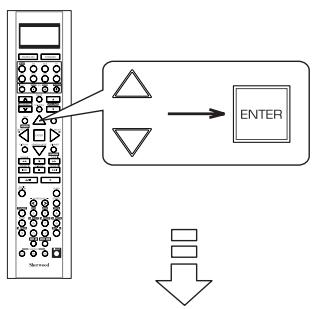
Example: When selecting the VIDEO 1
VIDEO 1 CONFIG
NAME :VIDEO 1
HDMI ASSIGN : HDMI 1
VIDEO ASSIGN : COMP 1
VIDEO MODE : AUTO
AUDIO ASSIGN : OPT 1
AUDIO MODE : AUTO
- Press the CURSOR UP(▲)/DOWN(▼) buttons to select the NAME, then press the ENTER button.
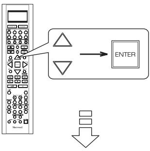
VIDEO 1 CONFIG >NAME :VIDEO 1
The first digit flickers.
- Press the CURSOR LEFT(▲)/ RIGHT(▶) buttons to select the desired digit.

-
Then the selected digit will flicker.
-
Press the CURSOR UP(▲)/DOWN(▼) buttons to enter the desired character on the flickering digit.
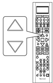
- You can enter the desired among blank, A ~ Z, a ~ z, 0 ~ 9, (), *, +, -, -, /.
- Repeat the above steps 3 and 4 to enter the desired characters on the rest of the digits.
- Confirm your entry.
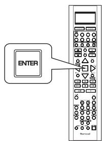
- The name is stored in the memory.
To resume its factory input source name.
- Make a blank on each digit and press the ENTER button.
SETTING THE SPEAKER / ROOM EQ SETUP
- After you have installed this receiver and connected all the components, you should adjust the speaker settings for the optimum sound acoustics according to your environment and speaker layout.
- Even when you change speakers, speaker positions, or the layout of your listening environment, you should adjust the speaker settings, too.
- When performing the AUTO SETUP procedure, you need not perform the SPEAKER CONFIGURATION, SPEAKER DISTANCE, SPEAKER CROSSOVER and CH LEVEL SETUP procedures.
SPEAKER/R.EQ SETUP
AUTO SETUP
SPEAKER CONFIG SPEAKER DISTANC SPEAKER CROSSROOM EQ SETUP
RETURN TO MAIN MENU
- AUTO SETUP: To set the speaker setup and channel level setup automatically.
- SPEAKER CONFIGURATION : To adjust the speakers depending on whether they are connected or not.
- SPEAKER DISTANCE: To select the distance between the listening position and each speaker to set the delay time automatically for optimum surround playback.
- SPEAKER CROSSOVER: To select the desired crossover frequency.
- ROOM EQ SETUP : To adjust the room EQ as desired.
When selecting the AUTO SETUP
- Auto Setup lets you avoid troublesome listening-based speaker setup and achieve good surround sound. Auto Setup has the feature that provides the optimum listening environment at the listening position in your room, where there are often multiple listeners viewing programs together. You should connect the supplied microphone to the SETUP MIC jack so that this receiver can analyze the information from a series of test tones emitted from speakers at the listening position and can adjust the configuration, distance, sound level, crossover frequency and frequency response of each speaker automatically.
- If you want to personalize your speaker setup and channel level setup by making the settings manually, perform the "When selecting the SPEAKER CONFIGURATION" on page 59, "When selecting the SPEAKER DISTANCE" on page 60, "When selecting the SPEAKER CROSSOVER" on page 61, "Adjusting each channel level with test tone" on page 35 and "Adjusting the current channel level" on page 36.
- After the auto setup has been completed, set the room EQ as desired. (For details, refer to "When selecting the ROOM EQ SETUP" on page 62.)
Preparations
①. Check that the speakers are securely connected to this receiver.
- If your subwoofer has adjustable volume and crossover frequency, set the volume halfway and set the crossover frequency to the maximum or the low pass filter off.
②. Connect the supplied microphone to the SETUP MIC jack on the front panel.(For details, refer to "SETUP MIC JACK" on page 16.)
Notes :
- Because the microphone for Auto Setup is designed for use with this receiver, to use the auto setup function, do not use a microphone other than the one supplied with this receiver.
- After you have completed the auto setup procedure, disconnect the microphone.
1. Place the microphone on a flat level surface at the listening position.
- If possible, use a tripod, etc. to attach the microphone at the same height as your ears would be when you are seated in your listening position.
- Ensure there are no obstacles between the speakers and the microphone.
Continued
- Press the CURSOR UP(▲)/DOWN(▼) buttons to select the AUTO SETUP, then press the ENTER button.


AUTO SETUP
BEFORE STARTING THE
SYSTEM PLEASE PLUG
THE MIC. IN USING
When the auto setup has been completed.
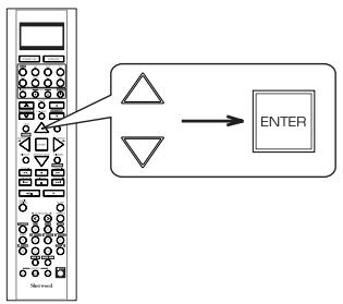

AUTO SETUP
COMPLETED

CANCEL
- Loud test tones are output successively and then if a series of auto setup procedure has been completed, "COMPLETED" will be displayed.
- To stop the auto setup procedure while performing it, press the ENTER button.
In such a case that the auto setup procedure is stopped before "COMPLETED" is displayed, the results of each adjustment may not be memorized.
- If there may be a problem with speaker or microphone connection, error message will be displayed. In this case, turn off the power, check the connection and then retry the auto setup procedure.
Notes :
- Before starting auto setup, be sure not to set the HDMI AUDIO OUT to ON.
- Because the test tones are loud, ensure there no infants or small children in the room.
- For best results, ensure the room is as quiet as possible during the auto setup procedure.
If there is too much ambient noise, the results may not be satisfactory.
- To memorize the results, press the CURSOR LEFT(▲)/ RIGHT(▶) buttons to select the APPLY, then press the ENTER button.
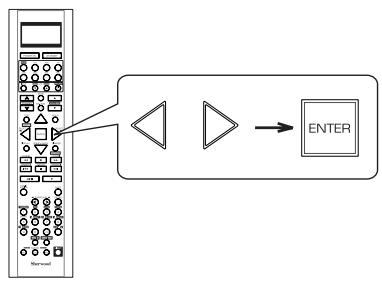
- Then the results are memorized and the SPEAKER/ ROOM EQ SETUP menu is displayed.
Each time the CURSOR LEFT(▲)/ RIGHT(▶) buttons are pressed, the APPLY or the CANCEL is selected. - When the CANCEL is selected, the results are not memorized.
- Check the results on each setup menu(SPEKER CONFIGURATION menu on page 59, SPEAKER DISTANCE menu on page 60, SPEAKER CROSSOVER menu on page 61 and CH LEVEL SETUP menu for "CALIBRATE" mode on page 64).
- If the results are not satisfactory, you can retry the auto setup procedure or personalize your speaker setup and channel level setup by making the settings manually. (For details, refer to "When selecting the SPEAKER CONFIGURATION" on page 59, "When selecting the SPEAKER DISTANCE" on page 60, "When selecting the SPEAKER CROSSOVER" on page 61, "Adjusting each channel level with test tone" on page 35 and "Adjusting the current channel level" on page 36.)
When selecting the SPEAKER CONFIGURATION
- Press the CURSOR UP(▲)/DOWN(▼) buttons to select the SPEAKER CONFIGURATION, then press the ENTER button.
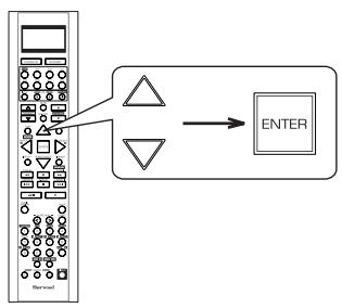

SPEAKER
CONFIG
FRONT
: YES
CENTER
YES
SURROU
YES
BACK/ML
2CH
SUBWOC
YES
RETURN
SETUP
MENU
- Press the CURSOR UP(▲)/DOWN(▼) buttons to select the desired speaker.
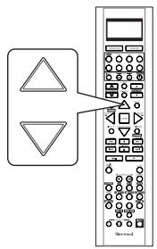
- Press the CURSOR LEFT(▲)/ RIGHT(▶) buttons to set the selected speaker as desired.
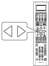
YES/NO: Select the desired depending on whether the speakers are connected or not.
2CH/1CH: Select the desired depending on the number of speakers connected to SURROUND BACK/MULTI channels.
Notes:
- When speakers are not set to "NO", you should set their distances from listening position and crossover frequencies according to their frequency characteristics. (For details, refer to "When selecting the SPEAKER DISTANCE" on page 60 and "When selecting the SPEAKER CROSSOVER" on page 61.)
- When the "SURROUND" is set to "NO", "BACK/MULTI" cannot be set to "2CH" or "1CH".
-
When the surround back channels' power amplifier is assigned to "BI-AMP" or "ROOM 2", the "BACK/MULTI" cannot be selected. (For details, refer to "When selecting the AMP ASSIGN" on page 49.)
-
Repeat the above steps 2 and 3 until the speakers are all set as desired.
When selecting the SPEAKER DISTANCE
- Press the CURSOR UP(▲)/DOWN(▼) buttons to select the SPEAKER DISTANCE, then press the ENTER button.


SPEAKER DISTANCE
UNIT FEET
FRONT LEFT 10.0ft
CENTER 10.0ft
FRONT RIGHT : 10.0 ft
SURR RIGHT 5.0ft
BACK/MULTIR 5.0ft
BACK/MULTIL 5.0ft
SURR LEFT 5.0ft
RETURN TO SETUP MENU
- Press the CURSOR UP(▲)/DOWN(▼) buttons to select the desired item.
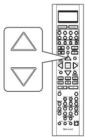
■ Note :
-
You cannot select the subwoofer and the speakers set to "NO".
-
Press the CURSOR LEFT(▲)/RIGHT(▶) buttons to set the selected item as desired.

■ When selecting the desired unit
- You can select either METERS or FEET.
- Once a unit is selected, the distances are automatically changed in the selected unit.
When setting the distance
- You can set the distance within the range of 0.1 9.0 meters in 0.1 meter intervals (or 0.5 30 feet in 0.5 feet intervals).
- Repeat the above steps 2 and 3 until the distances are all set as desired.
■About the speaker distance
When enjoying multi-channel surround playback with Dolby Digital and DTS sources, etc., it is ideal that the center, surround and surround back speakers should be the same distance from the main listening position as the front speakers. By entering the distance between the listening position and each speaker, the delay times of center, surround and surround back speakers are automatically adjusted to create an ideal listening environment virtually as if the center, surround and surround back speakers were at their ideal locations respectively.
When selecting the SPEAKER CROSSOVER
- Set the crossover frequency according to the frequency characteristics of the speakers connected. (For details on the frequency characteristics, refer to the operating instructions of the speakers.)
- If the frequency range of your speaker is 100Hz 20kHz , the crossover frequency should be set to 100Hz (or slightly higher).
-
The low frequencies below the crossover frequency are to output from subwoofer or the speakers which are set to "FULL RANGE" (when not using a subwoofer).
-
Press the CURSOR UP(▲)/DOWN(▼) buttons to select the SPEAKER CROSSOVER, then press the ENTER button.


SPEAKER X-OVER
| >FRONT | : | 80Hz |
| CENTER | : | 80Hz |
| SURROUND | : | 80Hz |
| BACK/MULTI | : | 80Hz |
RETURN TO SETUP MENU
- Press the CURSOR UP(▲)/DOWN(▼) buttons to select the desired speaker.
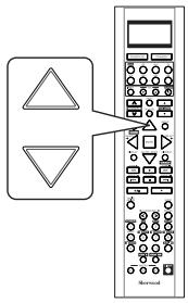
■ Note :
-
You cannot select the subwoofer and the speakers set to "NO".
-
Press the CURSOR LEFT(▲)/RIGHT(▶) buttons to set the crossover frequency as desired.
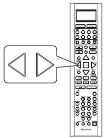
- You can adjust the crossover frequency within the range of 40 250Hz .
-
Select "FULL RANGE" when the selected speaker can fully reproduce the low frequencies below 40Hz .
-
Repeat the above steps 2 and 3 until the crossover frequencies are all set as desired.
When selecting the ROOM EQ SETUP
- The room EQ is a kind of room equalizer for your speakers. According to the acoustic characteristics of your room measured by the auto setup, the room EQ automatically adjusts the frequency response of your speakers.
- If you use different brands or sizes of speakers for some channels or have a room with unique acoustic characteristics, such as walls, furniture, and the dimensions or the shape of the room, we recommend using the room EQ.
Note:
- To use the room EQ, first you should finish measuring the acoustic characteristics of your room performing the auto setup.
(For details, refer to "When selecting the AUTO SETUP" on page 57.)
- Press the CURSOR UP(▲)/DOWN(▼) buttons to select the ROOM EQ SETUP, then press the ENTER button.
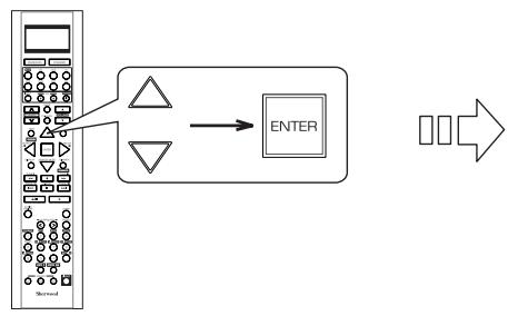
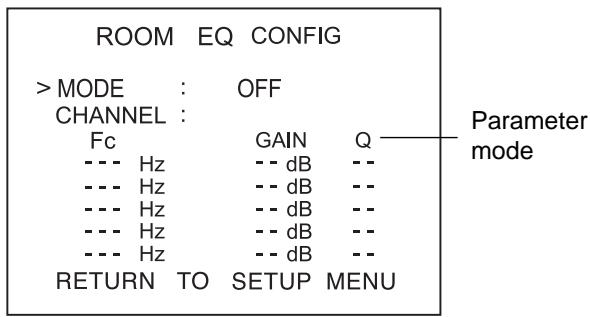
- Press the CURSOR UP(▲)/DOWN(▼) buttons to select the MODE.
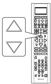
- Press the CURSOR LEFT(▲)/RIGHT(▶) buttons to select the desired room EQ mode.
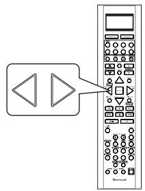
OFF: When turning off the room EQ.
FLAT: To adjust the frequency response of all speakers to the flattest response. This mode is suitable for multi channel music surround sound sources.
FRONT: To adjust the frequency response of the surround and the surround back speakers to match the characteristics of the front speakers.
USER: To adjust the tonal quality of the different speakers (except the subwoofer) manually.
Note:
- Only when the auto setup has been performed, the FLAT and the FRONT modes can be selected.
Continued
- When selecting the USER mode
- You can adjust the parametric EQ settings to optimize the frequency characteristics of this unit's parametric equalizer to match the acoustic characteristics of your room.
- The parametric equalizer uses a combination of the following three parameters to provide highly precise adjustment of the frequency characteristics.
※ Frequency
- This unit has 5 equalizer bands for each channel. You can adjust the specified frequency bands each within the following frequency ranges :
20 Hz ~ 120 Hz, 130Hz ~ 500 Hz, 550 Hz ~ 1.9 kHz, 2 kHz ~ 7.5 kHz, 8 kHz ~ 20 kHz
※ Gain
- This parameter is adjustable within the range of -24 +24 dB in 1 dB intervals.
※ Q factor
- The width of the specified frequency band is referred to as the Q factor. This parameter is adjustable within the range of 0 ~ 24 in 1 intervals.
Notes :
- When selecting the mode other than "USER" mode, you cannot select the EQ parameters for each channel.
- You cannot select the channel of the subwoofer and the speakers set to "NO".
①. Press the CURSOR UP(▲)/DOWN(▼) buttons to select the CHANNEL, then press the CURSOR LEFT(▲)/RIGHT(▼) buttons to select the desired channel.
②. Press the CURSOR UP(▲)/DOWN(▼) buttons to select the parameter mode, then press the CURSOR LEFT(▲)/RIGHT(▼) buttons to select the Fc (Frequency) mode.
③. Press the CURSOR UP(▲)/DOWN(▼) buttons to select the desired frequency band, then press the CURSOR LEFT(▲)/RIGHT(▼) buttons to select the desired frequency.
④. Repeat the above step ③ until the desired frequency is selected for each frequency band.
⑤. Repeat the above steps ② ~ ④ to adjust the gain of each specified frequency band.
⑥. Repeat the above steps ② ~ ④ to adjust the Q factor of each specified frequency band.
⑦. Repeat the above steps ① ~ ⑥ until the EQ parameters of other channels are all adjusted as desired.
SETTING THE CH LEVEL SETUP
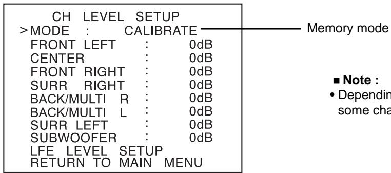
Note :
- Depending on the speaker settings("NO", etc.), some channels cannot be selected.
Adjusting the current channel level
- You can adjust the current channel levels as desired. These adjusted levels are just memorized into user's memory("CALIBRATE"), not into preset memory("REFERENCE 1", "REFERENCE 2").
-
After adjusting each channel level with test tone, adjust the channel levels either according to the program sources or to suit your tastes.(For details, refer to "Adjusting each channel level with test tone" on page 35.)
-
Press the CURSOR UP(▲)/DOWN(▼) buttons to select the desired channel.
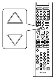
- When adjusting the LFE LEVEL
①. Press the CURSOR UP(▲)/DOWN(▼)buttons to select the LFE LEVEL SETUP, then press the ENTER button.
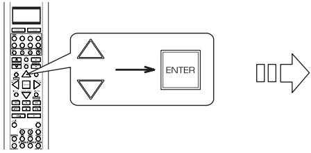
LFE LEVEL SETUP
DOLBY DIGITAL : 0dB DTS : 0dB
②. Press the CURSOR UP(▲)/DOWN(▼) buttons to select the desired program source.
- Press the CURSOR LEFT(▲)/RIGHT(▶) buttons to adjust the level of the selected channel or program source's LFE as desired.
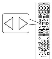
- The LFE level can be adjusted within the range of -10 0 dB and other channel levels within the range of -15 +15 dB
-
In general, we recommend the LFE level to be adjusted to 0 dB. (However, the recommended LFE level for some early DTS software is -10 dB.) If the recommended levels seem too high, lower setting as necessary.
-
Repeat the above steps 1 and 2 to adjust each channel level.
Memorizing the adjusted channel levels
- You can memorize the adjusted channel levels into preset memory("REFERENCE 1", "REFERENCE 2") and recall the memorized whenever you want.
- After performing the steps 1 ~ 3 in "Adjusting the current channel level" procedure on page 64, press the CURSOR UP(▲)/DOWN(▼) buttons to select a channel (, not the MODE (memory mode) and the LFE LEVEL SETUP), then press the ENTER button.
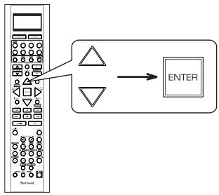
-
The "REFERENCE 1" indication flickers.
-
Press the CURSOR LEFT(▲)/RIGHT(▶) buttons to select the desired preset memory, then press the ENTER button.
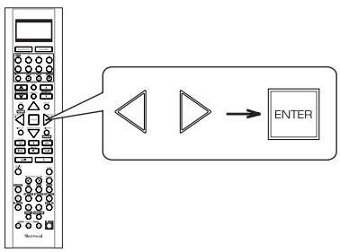
Each time the CURSOR LEFT( or RIGHT () button is pressed, "REFERENCE 1" or "REFERENCE 2" is selected.
- The adjusted channel levels have now been memorized into the selected memory.
Recalling the memorized channel levels
- Press the CURSOR UP(▲)/DOWN(▼) buttons to select the MODE记忆模式).
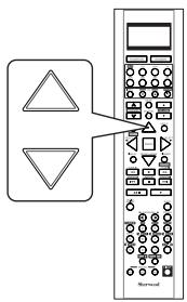
-
"CALIBRATE" may be displayed instead of "REFERENCE 1" or "REFERENCE 2".
-
Press the CURSOR LEFT(▲)/RIGHT(▶) buttons to select the desired one of REFERENCE 1 and REFERENCE 2.

- Then the channel levels memorized into the selected preset memory are recalled.
SETTING THE SOUND PARAMETER
SOUNDPARAMETER
NIGHT MODE
- NIGHT MODE : To adjust the dynamic range compression that makes faint sound easier to hear at low volume levels.
DOLBY PLII MUSIC : To adjust the various surround parameters for optimum surround effect. - DOLBY HEADPHONE: To select the desired listening mode for Dolby Headphone mode.
- DOLBY VIRTUAL SPEAKER: To select the speaker layout to be used actually for each Dolby Virtual Speaker mode.
When selecting the NIGHT MODE
- This function compresses the dynamic range of previously specified parts of the Dolby Digital sound track (with extremely high volume) to minimize the difference in volume between the specified and non-specified parts.
This makes it easy to hear all of the sound track when watching movies at night at low levels.
Notes:
- The night mode setting is valid only when the digital signals from the Dolby Digital program source are being input.
-
In some Dolby Digital softwares, the night mode setting may not be valid.
-
Press the CURSOR UP(▲)/DOWN(▼) buttons to select the NIGHT MODE, then press the ENTER button.
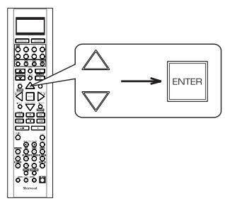

NIGHT MODE
DRC
:0.0(OFF)
RETURN TO SETUP MENU
- Press the CURSOR LEFT(▲)/ RIGHT(▶) buttons to adjust the dynamic range compression as desired.
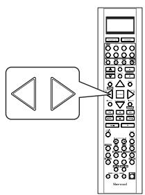

Lower compression
Higher compression
When selecting the DOLBY PLII MUSIC
- You can adjust the various surround parameters for optimum surround effect.
■ Note: -
The parameter settings are valid only when listening in either Dolby Pro Logic II Music mode or the Dolby Pro Logic IIx Music mode.
-
Press the CURSOR UP(▲)/DOWN(▼) buttons to select the DOLBY PLII MUSIC, then press the ENTER button.
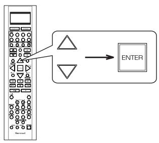

DOLBY PLII MUSIC
- Press the CURSOR UP(▲)/DOWN(▼) buttons to select the desired parameter.
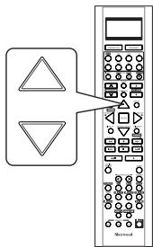
- Press the CURSOR LEFT(▲)/ RIGHT(▲) buttons to adjust the selected parameter as desired.
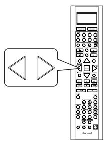
■When selecting the PANorama mode
This mode extends the front stereo image to include the surround speakers for an exciting "wraparound" effect with side wall imaging. Select "OFF" or "ON"(default value:OFF).
■When selecting the CENTER WIDTH control
This adjusts the center image so it may be heard only from the center speaker, only from the left/right speakers as a phantom image, or from all three front speakers to varying degrees. The control can be set in 8 steps from 0 to 7 (default value : 3).
■When selecting the DIMENSION control
This gradually adjusts the soundfield either towards the front or towards the rear. The control can be set in 7 steps from -3 to +3(default value : 0).
- Repeat the above steps 2 and 3 to adjust other parameters.
When selecting the DOLBY HEADPHONE
- You can select the desired listening mode for Dolby Headphone mode.
■ Note: -
The listening mode setting is valid only when playing analog stereo, PCM 2 channel or Dolby Digital 2 channel source.
-
Press the CURSOR UP(▲)/DOWN(▼) buttons to select the DOLBY HEADPHONE, then press the ENTER button.
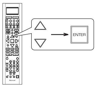

DOLBY HEADPHONE
DH MOVIE
RETURN TO SETUP MENU
- Press the CURSOR LEFT(▲)/ RIGHT(▶) buttons to select the desired listening mode.

MOVIE : This provides the surround effect suitable for movie sources.
MUSIC 1: This provides the surround effect suitable for music sources.
MUSIC 2 : This provides less surround effect compared to MUSIC 1 mode.
When selecting the DOLBY VIRTUAL SPEAKER
- You can select the speaker layout to be used actually for each Dolby Virtual Speaker mode.
■ Note: -
The speaker layout settings are valid only when listening in a Dolby Virtual Speaker mode.
-
Press the CURSOR UP(▲)/DOWN(▼) buttons to select the DOLBY VIRTUAL SPEAKER, then press the ENTER button.
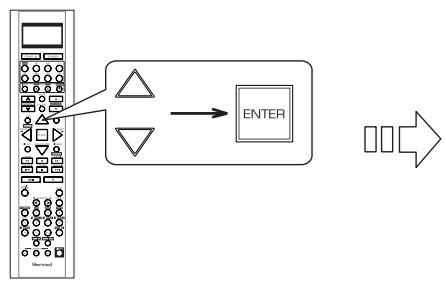
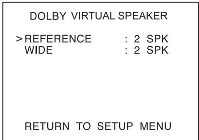
- Press the CURSOR UP(▲)/DOWN(▼) buttons to select the desired Dolby Virtual Speaker mode.

- Press the CURSOR LEFT(▲)/RIGHT(▶) buttons to select the desired speaker layout.
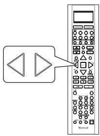
■ When selecting the Dolby Virtual Speaker Reference mode
2 SPK : When using 2 front speakers only.
3 SPK : When using 2 front and center speakers.
■ When selecting the Dolby Virtual Speaker Wide mode
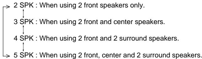
■ Note:
-
When the speakers are set to "NO", the corresponding speaker layouts cannot be selected.
-
Repeat the above steps 2 and 3 to select the desired speaker layout for another Dolby Virtual Speaker mode.
SETTING THE MULTI ROOM SETUP
- The ROOM 2 function allows enjoying one source in the main room while playing another in a different room at the same time.
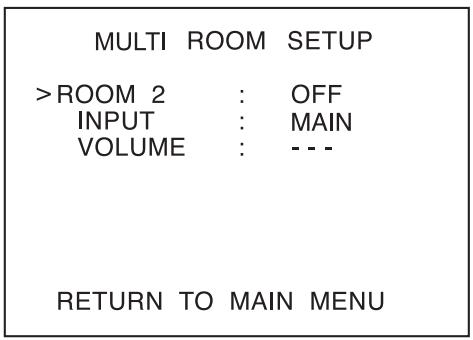
- ROOM 2 : To turn on or off the ROOM 2 function.
- INPUT: To select the desired ROOM 2 source.
- VOLUME: To adjust the volume on the power amplifier assigned to "BACK → ROOM 2" or "ROOM 2".
Notes:
- The analog signals from the EXTERNAL INs and the digital signals cannot be output to the different room, meaning no playback in a different room.
-
You cannot play the ROOM 2 source in any surround mode.
-
Press the CURSOR UP(▲)/DOWN(▼) buttons to select the desired item.
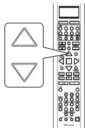
Note:
-
The VOLUME cannot be adjusted when the AMP ASSIGN is assigned to "BI-AMP" or "SURR BACK". (For details, refer to "When selecting the AMP ASSIGN" on page 49.)
-
Press the CURSOR LEFT(▲)/RIGHT(▶) buttons to set the selected item as desired.
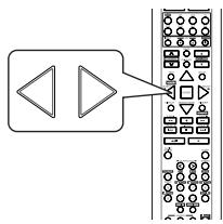
When selecting the ROOM 2
OFF : To turn off the ROOM 2 function.
↓
ON:To turn it on.
Notes:
- When the ROOM 2 is set to OFF, the INPUT and the VOLUME cannot be selected.
- When you do not use the ROOM 2 function, set the ROOM 2 to OFF to save electricity.
When selecting the INPUT
- You can select the desired among MAIN source, TUNER, CD, AUX, TAPE, VIDEO 1 ~ VIDEO 4 as a ROOM 2 source.
Note: - When the EXTERNAL IN is selected as a main input, if the MAIN source is selected as a ROOM 2 input, no audio signal can be heard in the different room (ROOM 2).
When selecting the VOLUME
- You can adjust the volume on the power amplifier assigned to "BACK ROOM 2" or "ROOM 2" when the ROOM 2 speaker terminals are connected to the speakers in a different room.
Note: - You can adjust the VOLUME only when the surround back channels' power amplifier is assigned to "BACK ROOM 2" or "ROOM 2". (For details, refer to "When selecting the AMP ASSIGN" on page 49.)
Troubleshooting Guide
If a fault occurs, run through the table below before taking your receiver for repair.
If the fault persists, attempt to solve it by switching the receiver off and on again. If this fails to resolve the situation, consult your dealer. Under no circumstances should you attempt to repair the receiver yourself. This could void the warranty.
| PROBLEM | POSSIBLE CAUSE | REMEDY |
| No power | ·The AC input cord is disconnected. ·Poor connection at AC wall outlet or the outlet is dead or off. | ·Connect cord securely. ·Check the outlet using a lamp or another appliance. |
| No sound | ·The speaker wires are disconnected. ·The master volume is adjusted too low. ·The MUTE button is pressed to ON. ·Incorrect selection of input source. ·Incorrect connections between the components. ·The HDMI AUDIO OUT is set to ON. ·The settings related to audio are set incorrectly. | ·Check the speaker connections. ·Adjust the master volume. ·Press the MUTE button to cancel the muting effect. ·Select the desired input source correctly. ·Make connections correctly. ·Set it to OFF. (For details, refer to "When selecting the HDMI AUDIO OUT" on page 50.) ·Set the settings correctly. (For details, refer to "SETTING THE INPUT SETUP" on page 53.) |
| No sound from the surroundSpeakers | ·Surround mode is switched off(stereo mode). ·Master volume and surround level are too low. ·Monaural source is used. ·Surround speaker setting is "NO". | ·Select a surround mode. ·Adjust master volume and surround level. ·Select a stereo or surround source. ·Select the desired surround speaker setting. |
| No sound from the centerspeaker | ·Dolby Virtual Speaker, stereo mode, etc is selected. ·Center speaker setting is "NO". ·Master volume and center level are too low. | ·Select the desired surround mode. ·Select the desired center speaker setting. ·Adjust master volume and center level. |
| No sound from the surround backspeakers | ·The input signal format or the current surround mode cannot support the 7.1(or 6.1) surround. ·The surround back channels' power amplifier is assigned to "BI-AMP" or "ROOM 2". ·Master volume and surround back level are too low. ·Surround back speaker setting is "NO". | ·Under the proper situations, perform the 7.1(or 6.1) surround playback.(For details, refer to "ENJOYING SURROUND SOUND" on page 34.) ·Assign the power amplifier to the surround back channels.(For details, refer to "When selecting the AMP ASSIGN" on page 49.) ·Adjust master volume and surround back level. ·Select the desired surround back speaker setting. |
| No picture | ·Video connections between this unit and the monitor TV are not made correctly. ·Incorrect selection of input source on the monitor TV. ·The settings related to video are set incorrectly. | ·Make proper video connections. ·Select the input source correctly. ·Set the settings correctly. (For details, refer to "SETTING THE INPUT SETUP" on page 53.) |
| No picture with an HDMIconnection | ·HDMI connection between this unit and the monitor TV are not made correctly. ·The monitor TV or other equipments do not support HDCP. | ·Make proper HDMI connection. ·This unit will not output video signal unless the connected equipments supports HDCP. |
| Stations cannot be received | ·No antenna is connected. ·The desired station frequency is not tuned in. ·Antenna is in wrong position. | ·Connect an antenna. ·Tune in the desired station frequency. ·Move antenna and retry tuning. |
| Preset stations cannot bereceived | ·An incorrect station frequency has been memorized. ·The memorized stations are cleared. | ·Memorize the correct station frequency. ·Memorize the stations again. |
| Poor FM reception | ·No antenna is connected. ·The antenna is not positioned for the best reception. ·Weak signals. | ·Connect an antenna. ·Change the position of the antenna. ·Install an outdoor FM antenna. |
| Continuous or intermittent hissingnoise during AM reception,especially at night. | ·Noise is caused by motors, fluorescent lamps or lightning, etc. | ·Keep the receiver away from noise sources. ·Install an outdoor AM antenna. |
| Remote control unit does not operate. | ·Batteries are not loaded or exhausted. ·The remote sensor is obstructed. | ·Replace the batteries. ·Remove the obstacle. |
| OSD function is not available. | ·Video connections between this unit and the monitor TV are not made correctly. | ·Make proper video connections. |
Specifications
■ AMPLIFIER SECTION
Power output, stereo mode, 6 Ω, THD 1.0 %, 40 Hz~20 kHz | 2×100 W
Total harmonic distortion, at -3 dB, 6 Ω, 1 kHz | 0.05%
- Intermodulation distortion
60 Hz : 7 kHz= 4 : 1 SMPTE, 6 Ω, 95 W | 0.05%
- Input sensitivity/impedance
Line (CD, TAPE,VIDEO) 300 mV/47kΩ
- Signal to noise ratio, IHF "A" weighted
Line (CD, TAPE, VIDEO) | 100 dB
Frequency response
Line (CD, TAPE, VIDEO), 10 Hz ~ 100 kHz | +0, -3 dB
Output level
ROOM 2 OUT, 2.2k 300 mV
- Bass/Treble control, 100 Hz/10 kHz | ±10 dB
- Surround mode, only channel driven
Front power output, 6 Ω, 1 kHz, THD 1.0 % | 110W / 110 W
Center power output, 6 Ω, 1 kHz, THD 1.0 % | 110 W
Surround power output, 6 Ω, 1 kHz, THD 1.0 % | 110 W / 110W
Surround back (/MULTI)/ ROOM 2 power output, 6 Ω, 1 kHz, THD 1.0 % | 110W / 110W
DIGITAL AUDIO SECTION
Sampling frequency 32,44.1,48,96 kHz
- Digital input level
Coaxial, 75 Ω 0.5 Vp-p
Optical, 660 nm -15 ~ -21 dBm
VIDEO SECTION
Video format NTSC
- Input sensitivity(=Output level), 75 Ω
Video (Composite(normal)) | 1 Vp-p
(chrominance signal)
Component video (R-Y signal)
(B-Y signal)
(Y signal)
MI connector
19 p
1 Vp-p
1 Vp-p
0.286 Vp-p
0.5 Vp-p
0.5 Vp-p
1.0 Vp-p
FM TUNER SECTION
Tuning frequency range 87.5~108 MHz
- Usable sensitivity, THD 3%, S/N 30 dB | 12.8 dBf
- 50 dB quieting sensitivity, mono/stereo | 20.2 / 45.3 dBf
- Signal to noise ratio, 65 dBf, mono/stereo | 70/65 dB
Total harmonic distortion, 65 dBf,1 kHz, mono/stereo 0.5/0.8%
- Frequency response, 30 Hz 15kHz ± 3 d B
- Stereo separation, 1 kHz | 32 dB
- Capture ratio 4.0 dB
IF rejection ratio 60 dB
AM TUNER SECTION
Tuning frequency range 520~1710 kHz
- Usable sensitivity 500 V / m
- Signal to noise ratio | 40 dB
- Selectivity 25 dB
GENERAL
-
Power supply | 120 V 60 Hz
Power consumption 3.7 A -
Switched AC outlets | TOTAL 120 W (1 A) max.
-
Dimensions (W × H × D, including protruding parts) 440 × 141 × 370 mm(17-3/8 × 5-1/2 × 14-1/2 inches)
Weight (Net) 10.1 kg (22.3 lbs)
Note: Design and specifications are subject to change without notice for improvements.
Setup Code Table
TV
AOC 005 003
Admiral 041 031
Aiko 014
Akai 005
Alaron 026
Ambassador 024
America Action 027
Ampro 043
Anam 027 047 048 049
Audiovox 030 027 014 034
Baysonic 027
Belcor 003
Bell & Howell 019 001
Bradford 027
Brockwood 003
Broksonic 028 031
CXC 027
Candle 005 011
Carnivale 005
Carver 010
Celebrity 050
Cineral 030 014
Citizen 012 005 011 006 014
Concerto 011
Contec 027
Craig 027
Crosley 010
Crown 027 006
Curtis Mathes 007 010 019 008 030 041
012 005 016 011 001 006
022 032 038 040
Daewoo 030 003 006 014 034 035
Daytron 003
Denon 016
Dumont 002 003
Dwin 044 036
Electroband 050
Emerson 019 028 031 027 029 025
003 026 006 024 034 035
Envision 005
Fisher 019
Fujitsu 026
Funai 027 026 023
Futuretech 027
GE 007 008 030 041 029 025
004 015 038 040
Gibraltar 002 005 003
Goldstar 005 025 003 011
Gradiente 009 011
Grunpy 027 026
Hallmark 025
Harley Davidson 026
Harman/Kardon 010
Havard 027
Hitachi 016 011 018
Infinity 010
Inteq 002
JBL 010
JCB 050
JVC 009 046
KEC 027
KTV 027 005 006
Kenwood 005 003
LG 011 003
LXI 007 010 019 020 025
Logik 001
Luxman 011
MGA 017 005 025 003
MTC 012 005 003 011
Magnavox 010 005 026
Magestic 001
Marantz 010 005
Matsushita 042
Magatron 025 016
Memorex 019 042 031 017 025 011
001
Midland 007 002 008 006 015
004
Mitsubishi 041 017 025 003
Motorola 041
Multitech 027
NAD 020 025 022
NEC 005 003 011
NTC 014
Nikko 005 025 014
Onwa 027
Optimus 019 042 022
Optonica 041 021
Orion 028 031 026
Panasonic 008 042
Penney 007 020 008 012 005 025
004 003 011 006 015 040
Pilco 010 031 005 016 003
Philips 010
| Pilot | 005 | 003 | 006 | |||||||||||||||||||||||||||
| Pioneer | 022 | |||||||||||||||||||||||||||||
| Portland | 003 | 006 | 014 | |||||||||||||||||||||||||||
| Prism | 008 | |||||||||||||||||||||||||||||
| Proscan | 007 | |||||||||||||||||||||||||||||
| Proton | 025 | 032 | ||||||||||||||||||||||||||||
| Pulsar | 002 | 003 | ||||||||||||||||||||||||||||
| Quasar | 008 | 042 | 021 | |||||||||||||||||||||||||||
| RCA | 007 | 008 | 041 | 003 | 013 | 015 | ||||||||||||||||||||||||
| 037 | 038 | 039 | 040 | |||||||||||||||||||||||||||
| Radio Shack | 007 | 019 | 021 | 027 | 005 | 025 | ||||||||||||||||||||||||
| 003 | 011 | 006 | ||||||||||||||||||||||||||||
| Realistic | 019 | 021 | 027 | 005 | 025 | 003 | ||||||||||||||||||||||||
| 011 | 006 | |||||||||||||||||||||||||||||
| Runco | 002 | 005 | 033 | |||||||||||||||||||||||||||
| SSS | 027 | 003 | ||||||||||||||||||||||||||||
| Sampo | 005 | 006 | ||||||||||||||||||||||||||||
| Samsung | 012 | 005 | 025 | 003 | 011 | 045 | ||||||||||||||||||||||||
| Samsux | 006 | |||||||||||||||||||||||||||||
| Sansei | 030 | |||||||||||||||||||||||||||||
| Sansui | 031 | |||||||||||||||||||||||||||||
| Sanyo | 019 | |||||||||||||||||||||||||||||
| Scimitsu | 003 | |||||||||||||||||||||||||||||
| Scott | 025 | |||||||||||||||||||||||||||||
| Scott | 028 | 027 | 025 | 003 | 026 | |||||||||||||||||||||||||
| Sears | 007 | 010 | 019 | 020 | 025 | 026 | ||||||||||||||||||||||||
| 011 | 006 | |||||||||||||||||||||||||||||
| Semivox | 027 | |||||||||||||||||||||||||||||
| Semp | 020 | |||||||||||||||||||||||||||||
| Sharp | 041 | 021 | 006 | |||||||||||||||||||||||||||
| Sherwood | 000 | |||||||||||||||||||||||||||||
| Shogun | 003 | |||||||||||||||||||||||||||||
| Signature | 001 | |||||||||||||||||||||||||||||
| Sony | 050 | |||||||||||||||||||||||||||||
| Soundesign | 027 | 025 | 026 | |||||||||||||||||||||||||||
| Squareview | 023 | |||||||||||||||||||||||||||||
| Starlite | 027 | |||||||||||||||||||||||||||||
| Supreme | 050 | |||||||||||||||||||||||||||||
| Sylvania | 010 | 005 | ||||||||||||||||||||||||||||
| Symphonic | 023 | |||||||||||||||||||||||||||||
| TMK | 025 | 011 | 024 | |||||||||||||||||||||||||||
| Tandy | 041 | |||||||||||||||||||||||||||||
| Technics | 008 | 042 | ||||||||||||||||||||||||||||
| Technoi Ace | 026 | |||||||||||||||||||||||||||||
| Techwood | 008 | 011 | ||||||||||||||||||||||||||||
| Teknika | 010 | 027 | 017 | 012 | 003 | 026 | ||||||||||||||||||||||||
| 011 | 001 | 006 | 014 | |||||||||||||||||||||||||||
| Telefunken | 011 | |||||||||||||||||||||||||||||
| Toshiba | 019 | 020 | 012 | |||||||||||||||||||||||||||
| Totevision | 006 | |||||||||||||||||||||||||||||
| Vector Research | 005 | |||||||||||||||||||||||||||||
| Victor | 009 | |||||||||||||||||||||||||||||
| Vidikron | 010 |
| Headquarter | 011 | |||||
| Hitachi | 000 | 008 | 026 | |||
| Hughes Net.Sys | 008 | |||||
| JVC | 014 | 026 | ||||
| Jensen | 026 | |||||
| KEC | 005 | 025 | ||||
| KLH | 015 | |||||
| Kenwood | 014 | 026 | 006 | |||
| Kodak | 004 | 005 | ||||
| LXI | 005 | |||||
| Lloyd's | 000 | |||||
| Logik | 015 | |||||
| MEI | 004 | |||||
| MGA | 023 | 009 | ||||
| MGN Technology | 023 | |||||
| MTC | 023 | 000 | ||||
| Magnasonic | 025 | |||||
| Magnavox | 004 | 007 | 016 | 000 | 019 | |
| Magnin | 023 | |||||
| Marantz | 004 | 016 | ||||
| Marta | 005 | |||||
| Matsushita | 004 | 028 | 029 | |||
| Memorex | 004 | 005 | 027 | 007 | 012 | 023 |
| 000 | 017 | 021 | 011 | 031 | 032 | |
| Minolta | 008 | |||||
| Mitsubishi | 027 | 014 | 009 | |||
| Motorola | 004 | 027 | ||||
| Multitech | 000 | 015 | ||||
| NEC | 017 | 014 | 026 | 006 | ||
| Nikko | 005 | |||||
| Noblex | 023 | |||||
| Olympus | 004 | |||||
| Opimus | 005 | 027 | 017 | 028 | 029 | 030 |
| 031 | 032 | |||||
| Orion | 020 | 021 | 001 | |||
| Panasonic | 004 | 028 | 022 | 029 | 031 | |
| Penny | 004 | 005 | 023 | 008 | 006 | |
| Pentax | 008 | |||||
| Philco | 004 | 021 | ||||
| Philips | 004 | 016 | ||||
| Pilot | 005 | |||||
| Pioneer | 014 | |||||
| Profitronic | 023 | |||||
| Proscan | 013 | |||||
| Protec | 015 | |||||
| Pulsar | 007 | |||||
| Quarter | 011 | |||||
| Quartz | 011 | |||||
| Quasar | 004 | 028 | 029 | 031 | ||
| RCA | 013 | 004 | 027 | 023 | 008 | 019 |
| Radio Shack | 000 | |||||
| Radix | 005 | |||||
| Randex | 005 |
| Realistic | 004 | 005 | 027 | 012 | 000 | 017 |
| 011 | ||||||
| Runco | 007 | |||||
| STS | 008 | |||||
| Samsung | 023 | 010 | 033 | |||
| Sanky | 027 | 007 | ||||
| Sansui | 000 | 014 | 021 | 026 | 024 | |
| Sanyo | 012 | 023 | 017 | 011 | ||
| Scott | 020 | 010 | 018 | 009 | ||
| Sears | 004 | 005 | 012 | 000 | 008 | 017 |
| 011 | ||||||
| Semp | 010 | |||||
| Sharp | 027 | |||||
| Shintom | 015 | |||||
| Shogun | 023 | |||||
| Singer | 015 | |||||
| Sony | 004 | 002 | 000 | 003 | ||
| Syvania | 004 | 016 | 000 | 009 | ||
| Symphonic | 000 | |||||
| TMK | 023 | |||||
| Tatung | 026 | |||||
| Teac | 000 | 026 | ||||
| Technics | 004 | 028 | ||||
| Teknika | 004 | 005 | 000 | |||
| Thomas | 000 | |||||
| Toshiba | 010 | 009 | ||||
| Totevision | 005 | 023 | ||||
| Unitech | 023 | |||||
| Vector | 010 | |||||
| Vector Research | 006 | |||||
| Video Concepts | 010 | |||||
| Videosonic | 023 | |||||
| Wards | 013 | 004 | 027 | 012 | 016 | 023 |
| 000 | 008 | 015 | 019 | |||
| White WestingHouse | 021 | 025 | ||||
| XR-100 | 004 | 000 | 015 | |||
| Yamaha | 006 | |||||
| Zenith | 007 | 000 | 021 | 003 | ||
| Ameira High | 004 (TV use 008) | |||||
| Brocksonic | 001 | |||||
| Colt | 015 | |||||
| Cutis Mathes | 004 (TV use 008) | |||||
| Daewoo | 025 | |||||
| Emerson | 001 | |||||
| Funai | 000 | |||||
| GE | 004 (TV use 008) | 013 (TV use 012) | ||||
| 027 (TV use 041) | 023 | |||||
| Hitachi | 004 (TV use 008) | 000 | ||||
| HQ | 000 | |||||
| Lloyds | 000 | |||||
| MGA | 023 | |||||
| Megavox | 016 (TV use 010) | 004 (TV use 008) | ||||
| 000 | ||||||
Magnin 023
Memorex 005 028 (TV use 025)
Mitsubishi 027 (TV use 041)
Orion 001
Panasonic 004 (TV use 008) 028 (TV use 042)
Penney 004 (TV use 008) 023
028 (TV use 042)
Quasar 004 (TV use 008) 028 (TV use 042)
RCA 013 (TV use 012) 004 (TV use 008)
027 (TV use 041)
Sansui 000
Sanyo 023
Sear 000 005
Sharp 027 (TV use 041)
Sony 002 (TV use 000)
Symphonic 000
Zenith 000
DVD
Harman/Kardon 009
JVC 008
Kenwood 005
Megavox 011
Mitsubishi 016
Onkyo 011
Panasonic 013
Philips 011 006
Pioneer 003 014 026
Proscan 002
RCA 002
Samsung 017
Sherwood 001 012 000 018 019
020 021 022 023 025
Sony 004
Technics 013
Theta Digital 014
Toshiba 011
Yamaha 013 007
Zenith 011 010
CBL
ABC 002 003 009 030
007 006 008
Allegro 018 021
Archer 018 026
Bell&Howell 009
Century 018
Citizen 018 021
Comtronics 014
Contec 011
Easten 001
Emerson 026
Everquest 010 014
Focus 022
Garrard 018
Gemini 010
General Instrument 033 276 006 034
GoldStar 017 040
Goodmind 026
Hamlin 012 020 004 013
Hitachi 006
Hytex 007
Jasco 010 018 021
Jerrold 002 007 033 032 009 010
006 034
Movie Time 015
NSC 015
Oak 011
Optimus 031
Panasonic 016 031
Philips 018
Pioneer 017 025
Popular Mechanics 022
RCA 031
Radio Shack 010 021 026 028
Recoton 022
Regal 012 020
Regency 001
Rembrandt 006
Sherwood 000
SL Marx 014
Smasung 017 014
Scientific Atlanta 003 023 030 027
Signal 010 014
Signature 006
Sprucer 031
Starcom 002 010
| Stargate | 010 | 014 | 026 |
| Starquest | 010 | ||
| TV86 | 015 | ||
| Teleview | 014 | ||
| Tocom | 007 | 008 | |
| Tusa | 010 | ||
| Unika | 018 | ||
| United Artists | 007 | ||
| Universal | 153 | 019 | |
| Viewstar | 015 | ||
| Zenith | 024 | ||
| Zentek | 022 |
SAT
| AlphaStar | 008 | ||
| Chaparral | 001 | ||
| Echostar | 009 | ||
| Expreevu | 009 | ||
| General Instrument | 016 | 015 | 018 |
| HTS | 009 | ||
| Hitachi | 011 | ||
| Hughes Net.Sys | 007 | ||
| JVC | 009 | ||
| Jerrold | 016 | 015 | |
| Megavox | 006 | 005 | |
| Memorex | 006 | ||
| Next Level | 006 | ||
| Panasonic | 017 | ||
| Philips | 006 | 005 | |
| Primestar | 016 | 015 | |
| RCA | 003 | 002 | 012 |
| Radio Shack | 018 | ||
| Realistic | 014 | ||
| Sherwood | 000 | ||
| Sony | 004 | ||
| Star Choice | 018 | ||
| Toshiba | 010 | ||
| Uniden | 006 | 005 | 014 |
| Zenith | 013 |
AUX-TAPE/MD
Sherwood
000 (for tape deck)
035 (for MD recorder)
AUX-LD
Denon 007
Mitsubishi 007
NAD 007
Pioneer 007
Sony 017 018
AUX-TAPE
| Aiwa | 004 | 034 | |
| Carver | 004 | ||
| Harman/Kardon | 016 | 004 | |
| JVC | 022 | 024 | |
| Kenwood | 008 | ||
| Megavox | 004 | ||
| Marantz | 004 | ||
| Onkyo | 012 | 025 | |
| Opimus | 002 | 020 | |
| Panasonic | 038 | ||
| Pioneer | 002 | 020 | 011 |
| Sansui | 004 | ||
| Sony | 021 | 014 | 026 |
| Technics | 038 | ||
| Victor | 024 | ||
| Wards | 002 | ||
| Yamaha | 010 | 009 |
AUX-AMP
Aiwa 029
Carver 023
Curtis Mathes 027
Denon 037
Harman/Kardon 040
Linn 023
Megavox 023
Marantz 023
Panasonic 039
Philips 023 040
Pioneer 003 027
Sony 019 033
Technics 039
Wards 003
Yamaha 028
AUX-HOME AUTOMATION
GE
043
Lutron
044
One For All
042
Radio Shack
043
Security System
042
Universal X10
042
X10
042
AUX-DBS
Aiwa
045
059 029
Fisher
005
Harman/Kardon
046
JBL
046
JVC
047
Jerrold
031
RCA
006
Scientific Artlanta
032
Sony
045
Starcom
031
AUX-ACCESsARY
Archer
013
GC Electronics
013
Jebsee
013
Rabbit
036
Radio Shack
013
CD
Aiwa
010 030
Burmester
019
California Audio Lab
002
Carver
010 (
012 020
DKK
001
Denon
028 034
Emerson
035
Fisher
012 033
Garrard
019 018
Genexxa
004 035
Harman/Kardon
010 011
Hitachi
004
JVC
007
Kenwood
003
016
024
025
Krell
010
LXI
035
Linn
010
MCS
002
MTC
019
Megavox
010 035
Mar
002 010 013
Mission
010
NSM
010
Nikko
033
Onkyo
008 026
Opimus
001
04
03
029
019
021
Panasonic
002 031
Parasound
019
Philips
010 023
Pioneer
004
35
Proton
010
QED
010
Quasar
002
RCA
012
35
Realistic
012
19
Rotel
010
SAE
010
Sansui
010 035
Sanyo
012
Scott
035
Sears
035
Sharp
029 013 037
Sherwood
013
038
040 041
000
Sony
001
Sounddesign
009
Tascam
019
Teac
019
033
Technics
002
Victor
007
Wards
010 006
Yamaha
005 015
Yorx
032