
AI202100 - Range hood GAGGENAU - Free user manual and instructions
Find the device manual for free AI202100 GAGGENAU in PDF.
| Product Type | Range hood |
| Brand | GAGGENAU |
| Model | AI202100 |
| Dimensions (W x D) | 998 x 648 mm |
| Maximum weight | 43 kg |
| Power supply | 230 V ~ 50 Hz |
| Lighting | Halogen 12 V / 20 W, dimmable |
| Number of speeds | 3 speeds + intensive mode |
| Delayed shut-off function | Yes (10 minutes) |
| Intermittent ventilation | Yes (5 min every hour) |
| Filter saturation indicator | Yes (flashing after 30 h) |
| Grease filter type | Stainless steel metal, dishwasher-safe (65 °C max) |
| Activated carbon filter | KF 001-010, annual replacement |
| Minimum distance to cooking surface | 600 mm (electric) / 650 mm (gas) |
| Automatic intensive mode shut-off | After 5 minutes |
| Mounting type | Ceiling or suspended, for extraction or recirculation |
| Available spare parts | Grease filters, carbon filter (KF 001-010), lamps (12 V/20 W/G4) |
| User manual | Free download as PDF |
Frequently Asked Questions - AI202100 GAGGENAU
User questions about AI202100 GAGGENAU
0 question about this device. Answer the ones you know or ask your own.
Ask a new question about this device
Download the instructions for your Range hood in PDF format for free! Find your manual AI202100 - GAGGENAU and take your electronic device back in hand. On this page are published all the documents necessary for the use of your device. AI202100 by GAGGENAU.
USER MANUAL AI202100 GAGGENAU
Operating and Assembly Instructions
AI 200 AI 201 AI 202 AI 203
Extractor Hood
natural_image
Top-down architectural rendering of a modern kitchen ventilation grille (no text or symbols visible)Preface
- Important notes Page 3-4
1.1 For your safety Page 3
1.2 Operating for the first time Page 4
1.3 About use Page 4 - Features Page 5
- Operation Page 6-8
- Cleaning and care Page 9-10
- Maintenance Page 11
- Assembly instructions Page 12-17
6.1 Technical data Page 12
6.2 Installation Page 12-17
Preface
natural_image
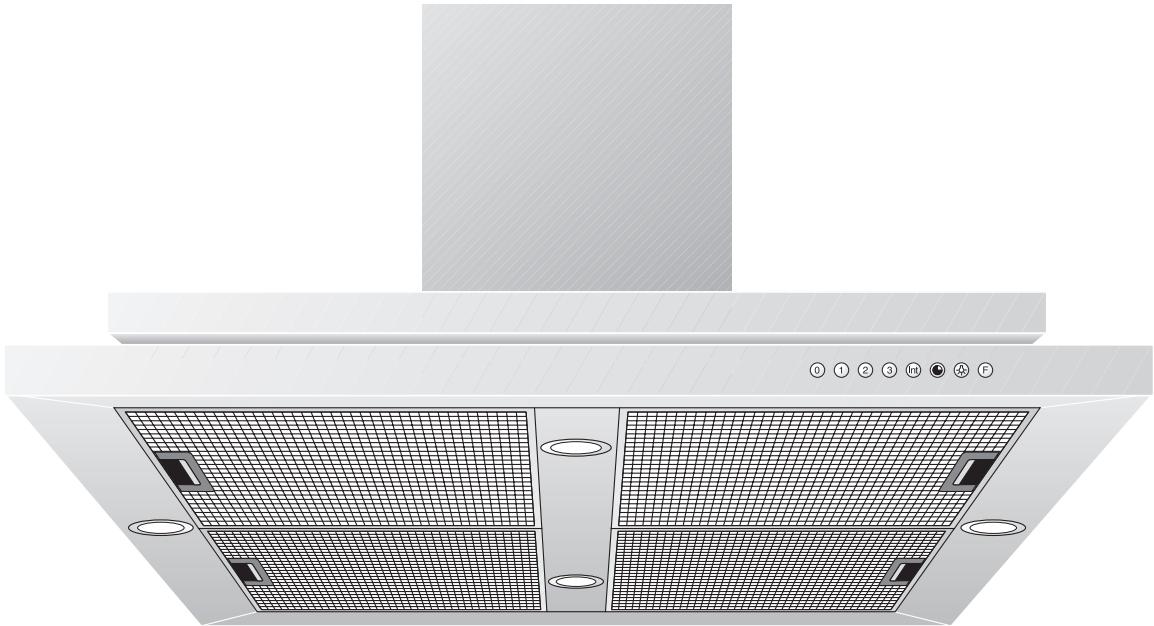
Technical illustration of a kitchen air conditioner unit with ventilation grilles and ventilation duct (no text or symbols)With your new extractor hood, working in the kitchen will be even more fun.
The appliance offers you a number of advantages:
- a good extraction capacity with low noise values,
- a large number of control functions,
- optimum illumination of the cooking surface by a dimmable halogen light.
To ensure that you will be able to use this appliance in all its diversity, read through the operating and assembly instructions conscientiously before operating it for the first time. The instructions contain important notes on use, installation and maintenance of the appliance.
On the following page you will find important notes on safety and operation. These will serve to ensure your personal safety and the lasting value of your appliance.
You will find notes on page 4 that you ought to observe before operating the appliance for the first time.
The chapters entitled “Structure and operating principle” and “Operation” will tell you all the things your extractor hood is capable of doing and how the appliance is operated.
Tips and hints in the chapter entitled “Cleaning and care” will make sure that your appliance will stay operable and beautiful for a long time.
And now we wish you lots of fun with your new extractor hood.
1.1 For your safety
- Damaged appliances must not be operated.
- The appliance must only be connected by an authorised specialist, paying attention to the relevant regulations of the power supply companies and the regional construction regulations.
Also observe the assembly instructions!
- Connecting cables must not come into contact with hot cooking surfaces.
- Do not operate the extractor hood without inserted lamps.
- Never operate the appliance without a grease filter.
- Hazardous or explosive substances and vapours must not be extracted!
- The user is responsible for expert use and the perfect condition of the appliance.
- Only ever operate the appliance under supervision.
- Caution! Over-greased filters are a fire risk! Only ever deep-fry under the extractor under constant supervision. Be sure to clean the grease filter on a regular basis and change the activated charcoal filter.
- Fire risk! Do not flambé meals under the extractor hood!
- Operation of the extractor hood above a hearth for solid fuels, which poses a fire risk (e.g. sparks) is only permitted, if the hearth possesses a closed and fixed lid. The current local regulations must be obeyed. This does not apply to gas hobs and gas cookers.
- Hobs may only be used under the extractor hood when pots and pans are placed on them!
- When using more than 3 gas-operated rings at the same time, please operate the extractor hood at level 2 or higher. This prevents a build-up of heat in the appliance.
- For safety reasons, do not place any heavy objects on the top of the appliance.
- Do not clean the appliance with a steam cleaning apparatus or with water pressure because this poses a risk of short-circuits.
- Isolate the appliance from the mains during every maintenance operation. To do this, remove the mains plug or actuate the corresponding fuse.
If the mains plug is not accessible, the appliance must be switched off at fuse point.
- Repairs must be carried out by authorised specialists, thus ensuring electrical safety.
- No warranty claims can be lodged in the event of damage caused by failure to observe these instructions.
- Adequate incoming air must be ensured if a wood, coal, gas or oil heater or an open hearth is operated in the same room as the one in which the hood is installed.
- Safe operation is possible whenever the partial vacuum in the place where the firing equipment is installed does not exceed 4 Pa (0.04 mbar). This can be achieved whenever the air needed for combustion is able to enter through openings that cannot be sealed, for example in doors, windows, incoming/exhaust air wall boxes or other technical means.
- If the appliance is to be operated only with the window open (to ensure adequate incoming air), you can use the window switch.
A switch (normally open) is fitted on the window. On the appliance, this switch is connected to the window switch terminal on the main electronics. The appliance can now only be operated when the window is open.
Important: the window switch must only be connected by an authorised specialist.
Note: the light function works without restriction.
- After a power failure, the extractor will not go on again automatically. You can recommence operation by turning a knob or by pressing any key.
Technical modifications reserved.
1.2 Operating for the first time
Before operating the appliance for the first time, please pay attention to the following notes:
- The appliance must be installed and connected by a specialist before it is operated for the first time.
- Conscientiously read through the operating and assembly instructions before operating the appliance for the first time.
- Remove the packaging from the appliance and dispose of it properly! Pay attention to the fact that there are accessories in the packaging! Keep packaging elements out of the reach of children!
- Thoroughly clean the appliance before using it for the first time (see chapter "Cleaning and care").
- Before operating the appliance for the first time, check that the mains connection is in proper working order.
1.3 About use
- The appliance is intended solely for use in the household and must not be put to any other uses.
- In the event of malfunctions, first of all check the household fuses. If the problem has nothing to do with the power supply, please contact your specialist dealer or your local Gaggenau after-sales service.
2. Features
text_image
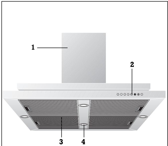
1 2 3 4Fig. 2
1 Ventilation duct
2 Control panel
3 Grease filters
4 Lighting
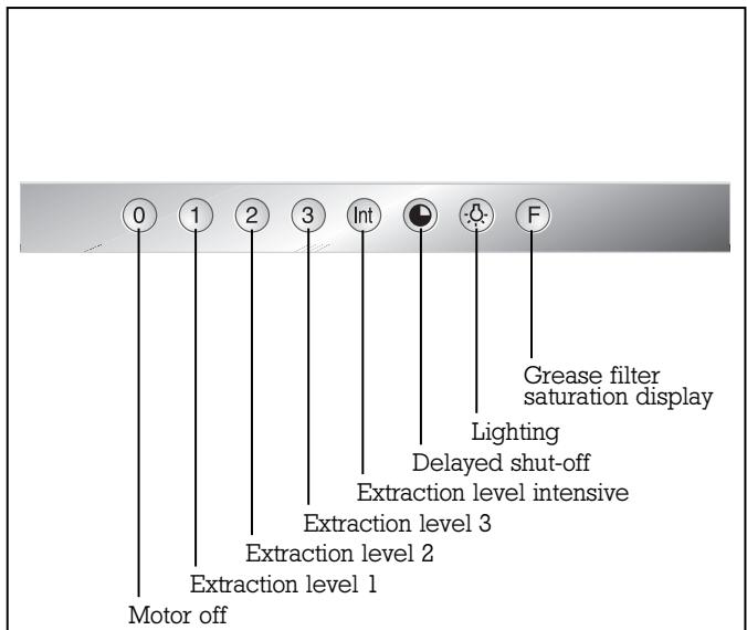
text_image
0 1 2 3 Int F Motor off Extraction level 1 Extraction level 2 Extraction level 3 Extraction level intensive Lighting Delayed shut-off Grease filter saturation displayFig. 3
Installation accessories for exhaust air mode
Stainless steel-design ventilation duct:
LK 010-016 for ceiling heights of 2.24 - 2.42 m
LK 010-026 for ceiling heights of 2.42 - 2.74 m
LK 010-036 for ceiling heights of 2.74 - 3.00 m
Aluminium-design ventilation duct:
LK 011-016 for ceiling heights of 2.24 - 2.42 m
LK 011-026 for ceiling heights of 2.42 - 2.74 m
LK 011-036 for ceiling heights of 2.74-3.00 m
Installation accessories for circulating air mode
Stainless steel-design ventilation duct:
LK 010-126 for ceiling heights of 2.42-2.74 m
LK 010-136 for ceiling heights of 2.74 - 3.00 m
Aluminium-design ventilation duct:
LK 011-126 for ceiling heights of 2.42 - 2.74 m
LK 011-136 for ceiling heights of 2.74 - 3.00 m
3. Operation
text_image
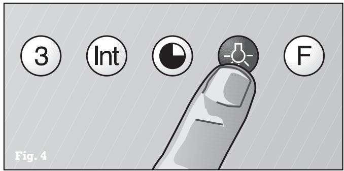
3 Int F Fig. 4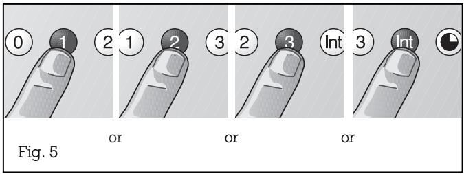
text_image
0 1 2 1 2 3 2 3 Int 3 Int Fig. 5 or or orAfter they have been pressed, all functions selection keys except 0 ("Motor off") are backlit in green.
Light
The lighting can be switched on or off, regardless of whether the extractor hood is in operation, by pressing the ⏻ key (see Fig. 4).
When you briefly press the ⏻ key, the lighting is increased up to the maximum level.
You can dim the lighting to the required level by keeping the ⏻ key pressed.
Fan levels
Three fan speeds and one intensive speed are available (see Fig. 5). You set the fan level required for each respective cooking situation by pressing the function selector keys 1, 2, 3 or Int.
text_image
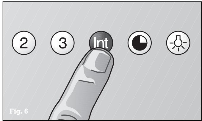
2 3 Int Fig. 6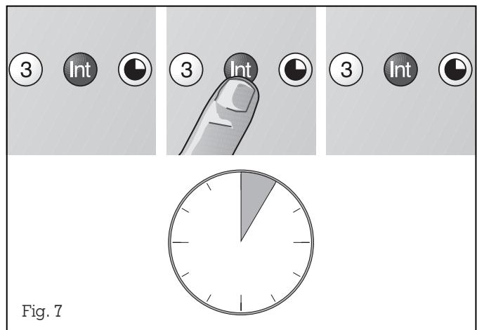
text_image
③ Int ③ Int ③ Int Fig. 7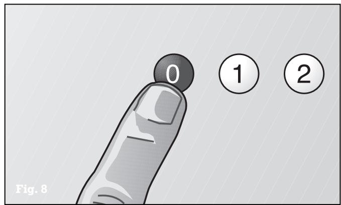
text_image
0 ① ② Fig. 8The Int key for the intensive level should be pressed when browning and frying in an open pan (see Fig. 6). If you have switched on the hood by selecting the intensive level, it will be switched off again automatically after 5 minutes.
If you press the Int key while the hood is running at fan level 1, 2 or 3, the electronic control will switch back automatically to the previously selected fan level after 5 minutes (see Fig. 7).
If you would like to end the intensive level before the five minutes have elapsed, press the 0 key ("Motor off") or select a different level (see Fig. 8). It is possible to switch off the extraction function at any time by pressing the 0 key (motor "off").
text_image
1 2 3 Int 1 2 3 Int 1 2 3 Int or or Fig. 9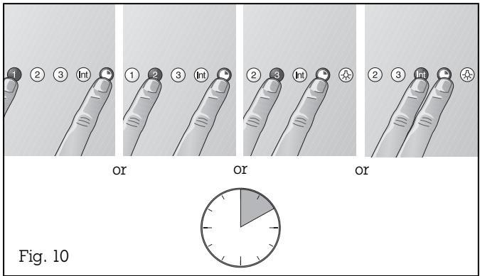
text_image
1 2 3 Int 1 2 3 Int or or or 2 3 Int or Fig. 10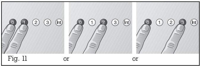
text_image
0 1 2 3 Int Fig. 11 or or 0 1 2 3 Int 0 1 2 3 Int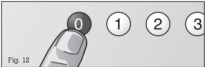
text_image
0 ① ② ③ Fig. 12Special functions:
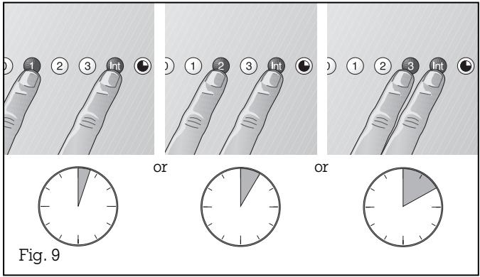
Intensive time:
You can set the intensive level running time to 3, 5 or 10 minutes by simultaneously pressing the Int key and the 1, 2 or 3 key and you can store this setting (see Fig. 9). When delivered, the appliance is set to five minutes, i.e. the combination of the Int key and the key 2.
Delayed shut-off:
Delayed shut-off is possible at any level. First press the required key 1, 2, 3 or Int and then press the Ⓞ key (see Fig. 10).
The delayed shut-off time for all levels is ten minu-tes. After these ten minutes, the ventilation switches off, but the lighting stays on.
Interval ventilation:
Interval ventilation is a special feature of this appliance which periodically activates the fan for five minutes every hour. You can activate this function by simultaneously pressing the 0 key and, depending on the required extraction capacity, the 1, 2 or 3 key (see Fig. 11).
This mode of operation is indicated by alternating illumination of the Ⓞ key together with the corresponding fan level indicator.
You can switch off interval ventilation by pressing the 0 key (see Fig. 12).
4. Cleaning and care
natural_image
Illustration of a kitchen fan with a hand inserting a card into the cover, showing internal components and a close-up of the handle (no text or symbols)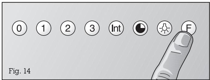
text_image
0 1 2 3 Int F Fig. 14Cleaning the grease filters
The grease filter saturation display F flashes after an operating time of 30 hours to you indicate to you that you should clean the grease filter (see Fig. 3). The grease filters can of course be cleaned at any time, even if the grease filter saturation display has not started to flash.
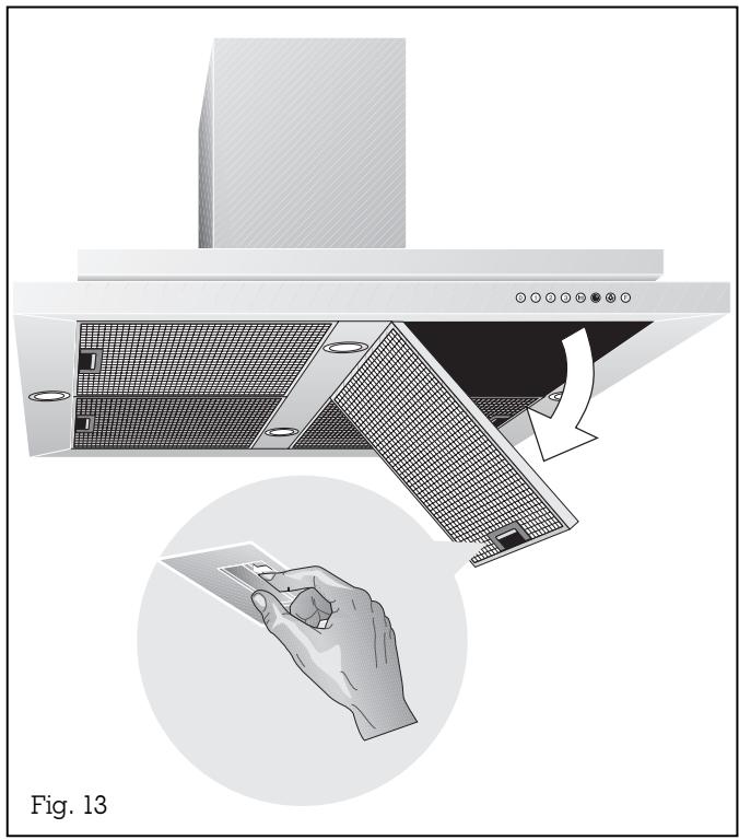
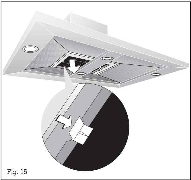
The stainless steel grease filters can be removed easily for cleaning (see Fig. 13):
Disconnect the power supply (switch off the fuse).
Grip the grease filter handle and push the slide towards the rear. Then pull the grease filter downwards out of the holder; repeat the operation for the other grease filters.
You can clean the stainless steel grease filters in a dishwasher at a maximum temperature of 65^ C, where it should be supported vertically to allow food or rinsing residues to drain off.
If possible, the inner parts of the housing should be wiped out in hot rinsing water when replacing the filters.
Caution:
when cleaning the inside of the housing, beware of protruding parts.
After having cleaned them, re-insert the grease filters in the extractor hood in reverse order.
Important:
the handles of both grease filters must be visible after assembly.
Press the F key to set the elapsed hours counter to zero. Flashing of the indicating lamp goes off.
Cleaning the extractor hood
Clean the exterior of your extractor hood with a soft cloth and mild detergent solution.
Do not use any strong, caustic or abrasive cleaning agents. Do not use any abrasive sponges or brushes either.
Clean the stainless-steel extractor hood (AI 200/AI 202) with stainless steel cleaner.
Do not place any objects with sharp-edged or rough bottoms (e.g. ceramic cups) on the hood.
natural_image
Technical illustration of a ceiling structure with an arrow indicating a component, shown in two views: one showing internal components and the other showing a cutaway view (no text or symbols)Circulating air mode
The activated charcoal filter eliminates kitchen smells in the circulating air mode. In normal use (1 to 2 hours daily), the activated charcoal filter must be replaced approximately once a year.
If no activated charcoal filter is installed, kitchen smells will not be eliminated.
The activated charcoal filter (KF 001-010) is available through your specialist dealer. It is not supplied with the appliance. Only use original filters.
Installing or replacing the activated charcoal filter
Remove the stainless steel grease filters. Position the activated charcoal filter from beneath the appliance into place and push in the clips on the side.
To remove the activated charcoal filter, push in the clips on the side and remove the activated charcoal filter downwardly.
Activated charcoal filters do not contain any dangerous substances. They can be disposed of through the household refuse collection.
natural_image
Diagram of a mechanical component with a circular housing and an arrow indicating rotation or movement (no text or symbols)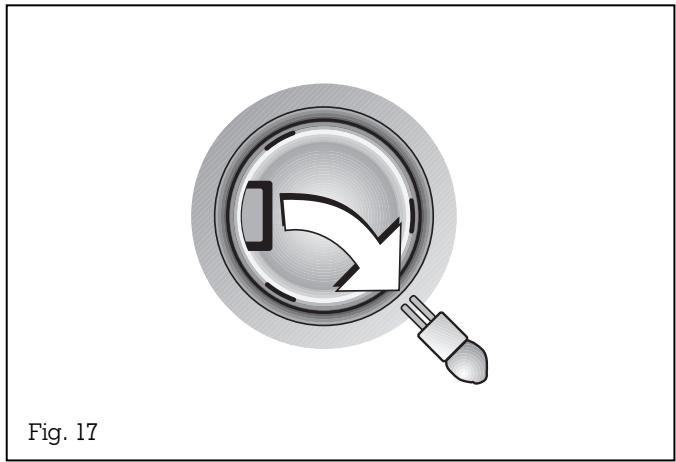
natural_image
Illustration of a magnifying glass with an arrow inside, no text or symbols presentDisconnect the appliance from the mains before carrying out any repairs.
In the event of malfunctions, first of all check the household fuses.
If the power supply is in proper working order, but the appliance is nevertheless not functioning, then please contact your specialist dealer or Gaggenau after-sales service. Specify the appliance type (see rating plate).
Repairs must only be carried out by authorised specialists, thus ensuring the safety of the appliance. Improper tampering will render all warranty claims null and void.
Lamp replacement
Caution: disconnect the power supply before replacing lamps (switch off the fuse)!
Caution: lamps may still be hot shortly after use! Risk of burns.
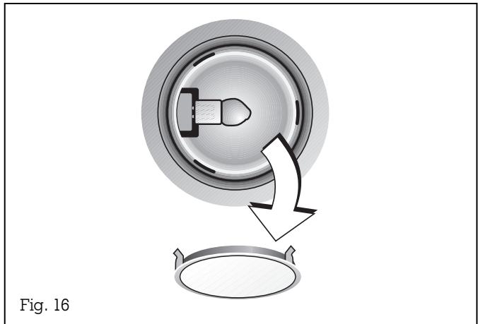
- Detach the ring from the lamp cover. Note: make sure that the glass will not fall out (Fig. 16).
- Pull out the lamp (Fig. 17).
Defective lamps must only be replaced by lamps of the same type! (12 V/20 W/G4 lampholder)
Inserting the lamp
- Insert the lamp in the lampholder.
Note: do not touch the halogen lamps with your hands. Use a cloth and touch the lamp only on its edges. - Engage the lamp cover.
- Connect the appliance to the mains again.
6. Assembly instructions
6.1 Technical data
AI 200: max. weight depending on version 45 kg dimensions 998 x 648 mm
AI 201: max. weight depending on version 45 kg dimensions 998 x 648 mm
AI 202: max. weight depending on version 43 kg dimensions 998 x 648 mm
AI 203: max. weight depending on version 43 kg dimensions 998 x 648 mm
Electrical connection
Pay attention to the rating plate data.
The mains connecting cable must at least correspond to the type H 05 VV-F G 0,75.
The appliance must only be connected by an authorised specialist. The specialist is responsible for perfect functioning of the appliance at its installation location. He must explain the operating principle of the appliance to the user with reference to the operating instructions. He must explain to the user how the appliance can be isolated from the mains whenever required.
Connection possibilities
The plug of the connecting cable is inserted into the socket on the ceiling. If this is not possible, the disconnection of all the poles of the appliance from the mains must be possible by way of the domestic fuse, or by using an accessible disconnecting device with a contact gap of at least 3.0 mm.
6.2 Installation
The applicable regulations of the energy supply companies and the regional construction regulations must be observed when installing the hood.
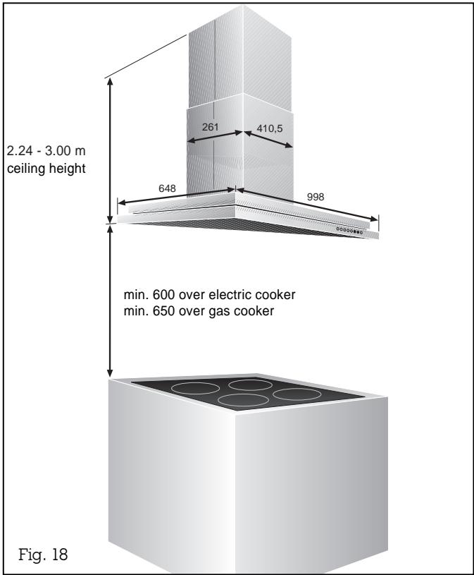
The minimum distance from the cooking surface to the bottom edge of the extractor hood is 600 mm for electrical appliances. The minimum distance from the bottom edge of the pot stand to the bottom edge of the extractor hood is 650 mm for gas appliances.
The hood can be used in the exhaust or circulating air mode. The exhaust air can be routed into a separate exhaust air shaft or directly into the open through the outside wall.
It is not allowed to pass the exhaust air into a flue or exhaust air chimney that is in operation or into a shaft that is linked to the heating basement. Consult the chimney sweep responsible for your district whenever you wish to pass the exhaust air into a chimney that is not in operation.
During the course of planning, a chimney sweep must be consulted if a room air-dependent hearth is operated in the same room as the one in which a hood is operated in the exhaust air mode. Adequate incoming air must be ensured. The applicable construction and safety regulations must be observed.
Adequate incoming air must be ensured if a wood, coal, gas or oil heater or an open hearth is operated in the same room as the one in which the hood is installed.
Safe operation is possible whenever the partial vacuum in the place where the firing equipment is installed does not exceed 4 Pa (0.04 mbar). This can be achieved whenever the air needed for combustion is able to enter through openings that cannot be sealed, for example in doors, windows, incoming/exhaust air wall boxes or other technical means.
Flexible aluminium pipes, corrosion-protected sheet metal pipes and exhaust air pipes whose material conforms to fire B1 in accordance with DIN 4102 can be used. Exhaust air pipes should have a nominal diameter of 150 mm.
Pay particular attention to ensuring that
- the exhaust air ducts and pipes are kept as short as possible
- the pipes are not laid at an acute angle, but as bends and that they are inserted into the shaft at an inclined upward angle and
- there are no cross-sectional constrictions in the upward direction (this reduces the volume flow).
As standard, the blow-out opening of the extractor hood is in the upward direction.
To pass exhaust air through the outer wall, we recommend the use of our telescopic wall box TM 150-045 (∅ 150).
Note:
To prevent the ingress of water, e.g. condensate or rain water from an uncovered exhaust air shaft, our condensate separator RV 060-150 must be installed in the exhaust air line. The condensate separator must still be accessible after installation.
The duct units listed below are available depending on the height of the ceiling:
Installation accessories for exhaust air mode
Stainless steel-design ventilation duct:
LK 010-016 for ceiling heights of 2.24 - 2.42 m
LK 010-026 for ceiling heights of 2.42 - 2.74 m
LK 010-036 for ceiling heights of 2.74 - 3.00 m
Aluminium-design ventilation duct:
LK 011-016 for ceiling heights of 2.24 - 2.42 m
LK 011-026 for ceiling heights of 2.42 - 2.74 m
LK 011-036 for ceiling heights of 2.74 - 3.00 m
Installation accessories for circulating air mode
Stainless steel-design ventilation duct:
LK 010-126 for ceiling heights of 2.42 - 2.74 m
LK 010-136 for ceiling heights of 2.74 - 3.00 m
Aluminium-design ventilation duct:
LK 011-126 for ceiling heights of 2.42-2.74 m
LK 011-136 for ceiling heights of 2.74 - 3.00 m
The dimensions above refer to a distance of 1.60 m from the floor to the bottom edge of the hood.
If required, custom made duct units are available at an extra charge.
The electrical socket must be placed within the ventilation duct on the ceiling.
text_image
2.24 - 3.00 m ceiling height 261 410,5 648 998 min. 600 over electric cooker min. 650 over gas cooker Fig. 18To use above gas cooker / gas hob
Important: do not use all burners on the highest setting simultaneously over a longer period of time (max. 15 minutes). This will pose a risk of burns when touching the hot appliance exterior or parts of the extractor hood may become damaged.
Switch the extractor hood to the highest setting when three or more burners of a gas cooker are used simultaneously.
The following note applies to extractor hood AI 202/203 only; this model does not have an integrated fan:
The extractor hood can only be used in exhaust air mode. The exhaust air is conveyed upwards through an externally attached fan via a ventilation shaft or directly into the open air through the outer wall.
The extraction function is realised by an external fan module. We recommend the fan modules GB 032-107 or GB 052/053-140 from our Gaggenau range; the extractor's electronic circuitry is optimised for these fan modules.
For the electrical connection between the extractor hood and external fan see installation instructions for the external fan.
For safety reasons, if the connecting cable to the external fan has been damaged, it must be replaced by the manufacturer or the after sales service or similarly qualified persons.
text_image
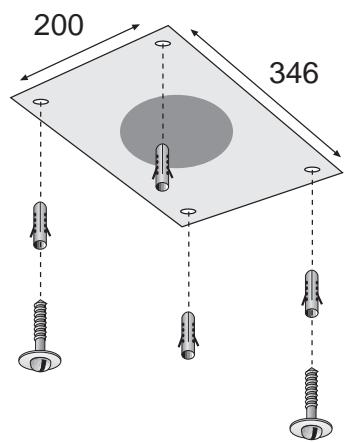
200 346Fig. 19
natural_image
Technical illustration of a mechanical assembly with labeled components, showing internal structure and mounting holes (no text or symbols)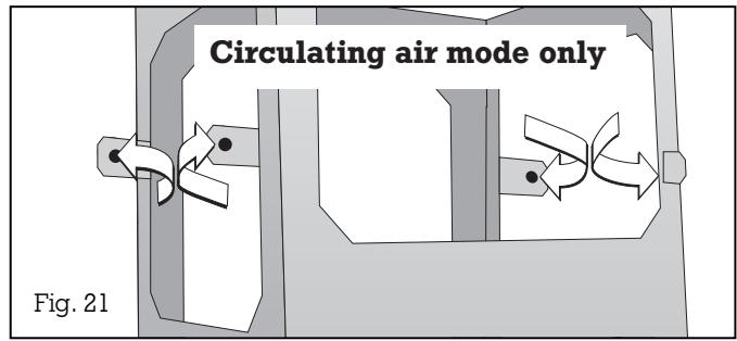
text_image
Circulating air mode only Fig. 21Note:
the extractor hood is to be installed to a kitchen ceiling or suspended ceiling. Ensure that the ceiling is capable of providing a firm hold for a maximum weight of hood and accessories of 45 kg.
Before marking the securing holes, make sure that no electricity wires or water pipes or other wires/ pipes are laid at the drilling points in the ceiling.
Before installation check the enclosed wall plugs and screws are suitable for your ceiling. If necessary use special wall plugs.
Installation of the extractor hood:
- Using the drilling template mark the position of the screws on the ceiling.
- Drill 4 holes ∅ 8 mm for the wall plugs. Push the plugs flush with the ceiling (Fig. 19).
- Turn two screws to a 10 mm gap. Both screws are placed in a position, in which at a later stage of the installation the key-holes of the supporting frame are found (namely back left and front right from the control panel of the hood).
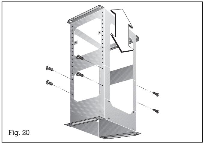
- Adjust the support frame to the desired height and secure with 8 screws (12 screws for the longer ventilation ducts). The length of the support frame can be adjusted in steps of 20 mm (Fig. 20).
ensure that the minimum distance between the hob and the extractor hood is maintained - 600 mm for an electric hob and 650 mm for a gas hob.
Circulating air mode only: there are four brackets, which fix the circulating air switch module to the top of the support frame. These should be bent outward in a 90° angle (Fig. 21).
Note:
natural_image
Technical diagram of a mechanical assembly with bolts and a central component (no text or symbols)Fig. 22
- Hang the support frame with the two key-holes to the two screws in the ceiling and attach it with all 4 screws to the ceiling. The marking "FRONT" must be on the same side as the control panel after installation.
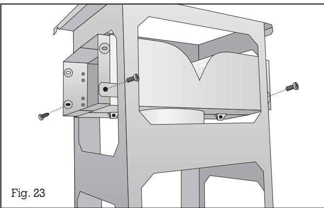
Circulating air mode only: assemble the circulating air switch module and fix it to support frame (Fig. 22 and 23). Cut the flexible air pipe to the required length and fix it to the extractor hood.
- Remove the cover plate from the rear of the support frame (Fig. 24).
natural_image
Technical line drawing of a mechanical assembly with mounting holes and internal components (no text or symbols)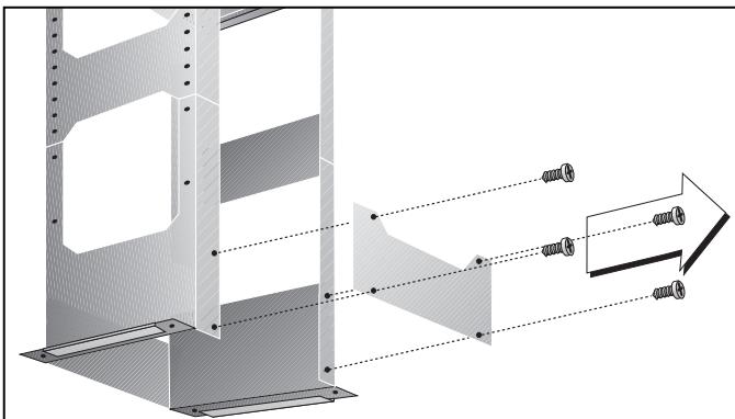
natural_image
Technical diagram of a structural assembly with dimension lines and bolted connection points (no text or symbols)Fig. 24
natural_image
Technical illustration of a mechanical assembly with a bolt inserted, showing structural components and a magnified inset (no text or symbols)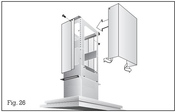
natural_image
Technical diagram of a mechanical device with internal components and directional arrows, labeled Fig. 26 (no text or symbols on the diagram itself)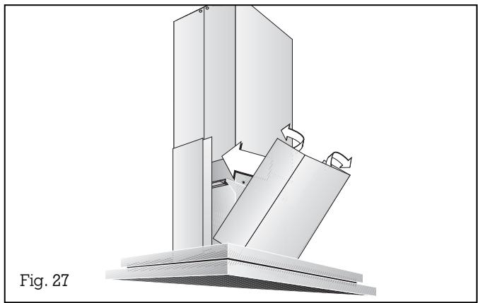
natural_image
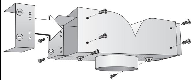
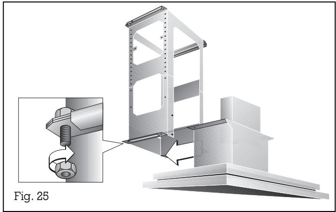
3D mechanical assembly diagram showing a folded paper or sheet with directional arrows indicating motion (no text or symbols)- Slide the extractor hood into the on the side of the support frame (Note: take care not to trap the mains connecting cable) and immediately secure the hood with 4 screws (Fig. 25).
- Screw the cover plate back on the rear of the support frame. The cover plate is important for the stability of the frame.
-
Connect the air outlet pipe to the extractor hood and to the exhaust air pipe on the ceiling (to the circulating air switch module for circulating air mode).
-
Establish the electrical connection.
-
Pull the protective film off the chimney's trims (if applicable).
-
Avoid damaging the sensitive surfaces when installing the ventilation ducts.
-
Secure the top chimney duct unit which has no magnetic strips with 2 screws on the top of the support frame (Fig. 26).
-
The second top chimney duct (which has magnetic strips) should be slightly bent open, in order to slide over the first chimney duct easily. Adjust (leave no gap) and fix with 2 screws to the top of the support frame (Fig. 26).
-
Place the bottom chimney duct unit which has no magnetic strips on the extractor hood. The second bottom chimney duct (which has magnetic strips) should be slightly bent open, in order to slide over the first chimney duct easily. Adjust to leave no gap (Fig. 27).
-
Circulating air mode only: insert the activated charcoal filter (see page 10). The activated charcoal filter is not supplied with the appliance.
-
Test that the appliance functions correctly.
Note: only dismantle the chimney ducts by hand. Do not use a tool, this might damage the ventilation ducts.
GAGGENAU
GAGGENAU HAUSGERÄTE GMBH CARL-WERY-STR. 34 · D-81739 MÜNCHEN
(089) 45 90-03 FAX (089) 45 90-23 47 www.gaggenau.com