
MYRA (systeme d'accroche) - Speaker FBT - Free user manual and instructions
Find the device manual for free MYRA (systeme d'accroche) FBT in PDF.


| Product type | Line array rigging system / flying accessories for FBT MYRA speakers |
| Brand | FBT |
| Model | MYRA (systeme d'accroche) |
| Compatible models | MYRA 214L, MYRA 218S |
| Material | Steel |
| Maximum modules for MYRA 214L | 24 modules (max load, safety factor 4:1); safe usage 12 modules (safety factor 8:1) |
| Maximum modules for MYRA 218S | 12 modules (max load, safety factor 4:1); safe usage 6 modules (safety factor 8:1) |
| Angle adjustment range | 0.25° to 8° increments, selectable via quick-release pins on side flange |
| Locking system | Automatic angle locking mechanism with ball-locking quick-release pins |
| Installation modes | Suspended (vertical array) or ground stack |
| Flybar MR-F214 weight | Frame 72.75 lb (33 kg), suspension bar 28.66 lb (13 kg) |
| Flybar MR-F218 weight | 22.04 lb (10 kg) |
| Trolley MR-T214 weight/capacity | 85.98 lb (39 kg), max 4 MYRA 214L modules |
| Trolley MR-T218 weight/capacity | 79.36 lb (36 kg), max 2 MYRA 218S modules |
| Horizontal aiming plate MR-FJ214 | Weight 18.73 lb (8.5 kg), allows horizontal adjustment up to ±10° |
| Pull-back bar MR-J214 | Weight 14.33 lb (6.5 kg), for additional downtilt (pull-back) |
| Extension feet MR-P214 | Stabilizing feet with adjustable tilt up to ±10°, for ground stacking |
| Top cover MR-TC214 | Protective cover for transport, fits on top of 4 stacked MYRA 214L modules |
| Safety standards | Complies with EN 13814, EN 1990, EN 1991-1-1, EN 1993-1-1, Directive 2006/42/EC |
| Maintenance | Regular visual inspection, lubrication of sockets and pins with WD-40 or equivalent, check for wear and damage |
| Installation requirements | Must be installed by qualified staff only; follow safety instructions and use certified lifting equipment |
| Software support | MYRA Rigging Safety Calculator available from FBT website for safety factor calculation |
Frequently Asked Questions - MYRA (systeme d'accroche) FBT
- MR-F214: Flybar and frame for MYRA 214L arrays
- MR-FJ214: Plate for horizontal aiming (±10°)
- MR-J214: Pull-back suspension bar
- MR-T214/MR-T218: Transport trolleys
- MR-P214: Extension feet for ground stacking
- MR-CT214: Top cover for transport
User questions about MYRA (systeme d'accroche) FBT
0 question about this device. Answer the ones you know or ask your own.
Ask a new question about this device
Download the instructions for your Speaker in PDF format for free! Find your manual MYRA (systeme d'accroche) - FBT and take your electronic device back in hand. On this page are published all the documents necessary for the use of your device. MYRA (systeme d'accroche) by FBT.
USER MANUAL MYRA (systeme d'accroche) FBT


AVVERTENZE
| Sicurezza | 1 |
| Note informative | 1 |
MYRA 214L
| Rigging closeup | 2 |
| Accessori | |
| MR-F214 | 3-4-5-6-7 |
| MR-FJ214 | 8-9 |
| MR-J214 | 10-11-12 |
| MR-T214 | 13-14 |
| MR-P214 | 15-16 |
| MR-CT214 | 17 |
MYRA 218S
| Rigging closeup | 18 |
| Accessori | |
| MR-F218 | 19-20-21 |
| MR-T218 | 22-23 |
AVVERTENZE DI INSTALLAZIONE 24-25-26-27
MECCANISMO DI BLOCCO DELL'ANGOLO 28
BARRA DI SOSPENSIONE FLYBAR MR-F 214


MR-FJ 214
DIMENSIONI

MR-J 214

Esempio 1


MR-T 214
Trolley per modulo MYRA 214L
Codice: 43898
Peso: 39 kg
Materiale: Acciaio
Max load: 4 moduli

PER IMPILARE I CARRELLI TRA LORO:


MR-P 214

MR-TC 214
Top cover
Codice: 44592


RIGGING CLOSEUP
MR-F 218
MR-T 218
DESCRIZIONE
PER IMPILARE I CARRELLI TRA LORO:

USO DEI GRILLI


USO DEI PIN
DISATTIVO

ATTIVO

BLOCCATO

TRASPORTO E ASSEMBLAGGIO

TRASPORTO E ASSEMBLAGGIO


Fig.3.1

TRASPORTO E ASSEMBLAGGIO
Fig.7
SELEZIONE ANGOLO
DISATTIVO

ATTIVO

BLOCCATO


ARRAY VERTICALE
ARRAY VERTICALE
ARRAY VERTICALE
DE-RIGGING


GROUND STACK
TRASPORTO E ASSEMBLAGGIO


ARRAY VERTICALE
TRASPORTO/STOCCAGGIO:
| Safety | 43 |
| Information notes | 43 |
MYRA 214L
| Rigging closeup | 44 |
| Accessories | |
| MR-F214 | 45-46-47-48-49 |
| MR-FJ214 | 50-51 |
| MR-J214 | 52-53-54 |
| MR-T214 | 55-56 |
| MR-P214 | 57-58 |
| MR-CT214 | 59 |
MYRA 218S
| Rigging closeup | 60 |
| Accessories | |
| MR-F218 | 61-62-63 |
| MR-T218 | 64-65 |
INSTALLATION INSTRUCTIONS 66-67-68-69
ANGLE LOCK MECHANISM 70
MYRA 214L INSTALLATION
| Transport and assembly | 71-72-73-74 |
| Angle selection | 75 |
| Suspended installation | 76-77 |
| De-rigging | 78-79 |
| Ground stack | 80-81 |
MYRA 218S INSTALLATION
| Transport and assembly | 82 |
| Vertical array | 83 |
CARE AND MAINTENANCE 84
SAFETY
- MYRA sound speaker must be installed using the flying accessories described in this manual and following the special assembly instructions by qualified staff only, strictly complying with the current regulations and safety standards in farce in the country of installation.
- FBT flying accessories are manufactured for their exclusive use with FBT MYRA system and have not been designed for being used with any other speaker or device.
- Any possible elements of the ceiling, floor or further supports where MYRA system is to be installed shall be able to safety bear the load.
- Always make sure that all attachment and fastening systems are of the appropriate size and load capacity
- Besides the main suspension system, all flying speakers in theatres, indoor stadiums or in several other work and/or leisure facilities shall be provided with an additional independent safety system with the adequate load capacity. Only steel cables and chains with certified load capacity can be used as an additional safety device.
Special attention was paid to the selection of the materials and manufacturing so as to permit high safely levels. The staff in charge of hanging the array system must be skilled and qualified; the installer/user will be responsible of ascertaining limits and lifting procedures for the structures to which the array will be attached. An improper use of the array suspension system may cause major damage to person and things.

FBT accepts no responsibility for any damage to people or objects if these instructions are not complied with or if the safety factor of all elements related to system suspension are not properly checked.
INFORMATION NOTES
MYRA system may be both flown and laid on the ground. System mounting type depends on the acoustic environment that needs being created and on the imposed assembly constraints. In the majority of common applications it is better to hang the system since this guarantees a more homogeneous coverage of the listening area. Every time the area for sound reproduction is located at a single level below an available attachment point and extends over a certain lenght, system suspension is the best solution because it permits to better distribute the sound pressure over the whole area where sound is reproduced.
During installation, make sure that system bearing framework is included in the calculation of the total weight, as well as the flybar, hoist chain, motors, cables and any additional weight.

Should the above safety regulations and calculations of the overall weight fail to be complied with, FBT Elettronica will not liable for any damages to persons and things.
In "flying" mode the accessories have been designed to suspend up to 24 MYRA 214L modules and up to 12 MYRA 218S modules.

Perform all the additional fastening techniques necessary for safe and stable use of the line array, also considering any atmospheric phenomena to which it may be subjected.
- Never use the handles or other elements of the speaker to suspend the modules.
In "ground-stack" mode, maximum 4 MYRA 214L modules and 2 MYRA 218S modules

Place the system on a flat and non-slippery surface; in the case of a support surface that has a slight inclination, it is necessary to adequately secure the installation with suitable mechanical means or straps.
FBT Elettronica makes available a software for calculating the safety factor according to the configuration used: MYRA Rigging Safety Calculator
For the calculation of the safety coefficient for use and the regulatory framework relating to the design criteria for steel structures, the following reference technical standards were observed:
- EN 13814 - Fairground and amusement park machinery and structures. Safety Industry Standards.
- EN 1990 - Eurocode 0 - Principles and requirements for the safety, operation and durability of structures
- EN 1991-1-1 - Eurocode 1 - Basis of structural design and action on structures.
- EN 1993-1-1 - Eurocode 3 - Design of steel structures. General rules.
- Directive 2006/42 / EC of the European Parliament and of the Council of 17 May 2006 relating to machinery and amending Directive 95/16 / EC
RIGGING CLOSEUP
MYRA speakers include a new generation “rigging” system, which is simple, easy to use and extremely precise. MYRA systems are transported on trolleys (4 modules per trolley in the case of the MYRA 214L model, and 2 in the case of the MYRA 218S model); during transport, the MYRA 214L models are assembled with their angles of aperture set to 8 degrees; the angle of aperture between speaker units is selected while the system is still on the ground, simply by inserting the angle selector quick release pin into the desired position; when the modules are raised, an automatic angle locking system ensures the speakers remain in their selected position. The modules remain in the open position until the user releases the angle locking mechanism, at which point the modules lock together once again.

FLYBAR MR-F 214
Flybar & Frame for MYRA 214L
Code: 43901
Weight: Frame 72.75 lb / Suspension bar 28.66 lb
Material: Steel
Safe use: 12 modules
Max load: 24 modules

| N. | DESCRIPTION |
| 1 | The suspension bar, connected to the frame, is used for suspending the system by means of lifting motors.Use one or two suspension bars according to the configuration needs (see page 46) |
| 2 | Frame for hooking the modules MYRA 214L |
| 3 | The suspension bar is equipped with two quick release pins to connect it to the frame and two straight shackles for suspension |
| 4 | 2 secondary safety hooks for chains or belts |
| 5 | 4 hooking points to be used for permanent fixed installation without the aid of the suspension bar ( see page 46 ) |
| 6 | No. 4 attachment points for the use of two suspension bars (see page 47) |
| 7 | No 4 fixing pins to suspend or hook MYRA 214L modules |
SUSPENSION BAR

| N. | DESCRIPTION |
| 1 | 19 different attachment points, spaced 2 "apart, to maintain the structural integrity of the bar |
| 2 | Attachment point of the MR-FJ214 accessory (see page 50) |
| 3 | Fixing points for central positioning of the suspension bar compared to the frame |
| 4 | Fixing points for the front or rear positioning of the suspension bar compared to the frame |
| 5 | Hooking point for the chain of the MR-J214 accessory (see page 52) |

Use of the frame only without suspension bar and with 4 lifting points. Recommended for an array configuration of a maximum of 24 MYRA 214L in fixed and permanent installations.

Use of frame and suspension bar with a single central lifting point. Recommended for an array configuration of a maximum of 16 MYRA 214L

Using two side suspension bars and two lifting points. Recommended for an array configuration from 16 to 24 MYRA 214L modules
MR-F 214 CONFIGURATIONS
The MR-F 214 flybar can be used for the installation of a line array consisting of up to 24 MYRA 214L modules

During installation, make sure that system bearing framework is included in the calculation of the total weight, as well as the flybar, hoist chain, motors, cables and any additional weight.
FBT will also place at your disposal a software which helps calculating the safety factor of the weakest point of unit suspension system according to the used configuration.
FBT accepts no responsibility for any damage to people or objects if these instructions are not complied with or if the safety factor of all elements related to system suspension are not properly checked.

Use of the suspension bar in a central position with two lifting points; this mode provides the best weight dispersion. Recommended for an array configuration from 16 to 24 MYRA 214L modules

Using two side suspension bars and four lifting points. Recommended for an array configuration from 16 to 24 MYRA_214L modules

EXTENSION BAR AND FRAME ORIENTATION
There are two different ways to position the suspension bar to the frame of the array.
NORMAL: This is the standard attachment position for most arrays. Allows from a minimum to a maximum amount of downward inclination.

REVERSE: this attachment position can be used when a greater upward inclination is required but with a limited number of modules.

CAUTION:
All quick release pins must always be placed in an attachment location. Do not suspend the system if any pins are hanging free.
DIMENSIONS


MR-FJ 214
Plate for horizontal aiming
Code: 44227
Weight: 18.73 lb
Material: Steel
Safe use: 12 modules
Max.load: 24 modules
| N. | DESCRIPTION |
| The MR-FJ214 is a rigging accessory using for controlling the horizontal aiming of an array. Two chain motors are attached to the accessory allowing for adjustments of up +/- 10 degrees. The MR-FJ214 can also be used to distribute the weight of an array to two points. | |
| 1 | Attachment point to suspension bar MR-F214 (hole N. 19) |
| 2 | Hooking / lifting points through of two motors with chain |
MR-FJ214 is typically positioned at the rear of an array and connected to the very last attachment hole of the flybar. The included 5/8-inch shackles are used to connect the MR-FJ214 to the flybar. Two rear motors are connected to the MR-FJ214 and horizontal aiming of the array is achieved by adjusting the position of the rear motor points.


DIMENSIONS

MR-J 214
Suspension bar for "pullback" implementation
Code: 44228
Weight: 14.33 lb
Material: Steel
Max. load: 6 modules

| N. | DESCRIPTION |
| Suspension bar that can be used to implementpull-back of the array. When used for pull-back, the MR-J214 can be attached to the bottom cabinet of an array and connected to a rear suspension point to allow for extra down-tilt. | |
| 1 | Lifting motor attachment point |
| 2 | Lateral attachment points to the MYRA 214L module |
| 3 | Lateral attachment points to the MYRA 214L module (LINK point) |

MR-J214 is a suspension bar that can be used to implement pull-back of a MYRA 214L array; can be attached to the bottom cabinet of an array and connected to a rear suspension point to allow for greater downtilt than is possible using the flybar MR-F214 alone.
The suspension bar is attached to the rear of the last module at the bottom; the corresponding attachment points are marked both on the side label of the accessory and on the side of the cabinet (LINK with LINK / MR-J214 with MR-J214 (fig.1).
The primary role of the suspension bar is as a pull-back attachment at the bottom of an array, to facilitate array configurations requiring a significant amount of downtilt. In this situation the flybar MR-F214 is used at the top of the array for the primary suspension point, with the MR-J214 attached to the bottom of the array and lifted by a second, rear motor point. The two motors are used to achieve the desired array downtilt.
Pull-backs are best suited for when the center of gravity (CoG) of an array falls outside the footprint of the array frame and alone cannot achieve the down angle needed for the design (Example 1). Using the suspension bar as a bottom frame can move the array CoG between the two suspension points, enabling almost any down angle to be achieved (Example 2).


Example 1

Center of gravity
Suspension points
Example 2

Center of gravity
Suspension points
DIMENSIONS


MR-T 214
Trolley for MYRA 214L module
Code: 43898
Weight: 85.98 lb
Material: Steel
Max. load: 4 modules

TO STACK THE TROLLEYS
- Position the trolley wheels so that they face inward.
- Align the wheels in the appropriate slots and stack

| N. | DESCRIPTION |
| Trolley for the transport of up to 4 MYRA 214L modules | |
| 1 | Fixing points to lock the front of the module |
| 2 | Attachment points to lock the rear of the module |
DIMENSIONS


MR-P 214
Extension feet for dolly transport
Code: 44591
DESCRIPTION
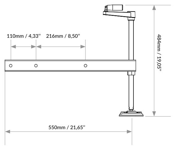
Stabilizing feet that provide adequate and stable support on the ground. For this purpose, the MR-T214 transport trolley is equipped with 4 slots. Each foot has pairs of holes to allow for different extension lengths; it is possible to tilt the stacked modules with a negative or positive angle of 10° (see page 81)

4 pins supplied
DIMENSIONS


MR-TC 214
Top cover
Code: 44592
When transporting an assembly consisting of 4 MYRA 214L modules, the MR-TC 214 is positioned on top of the top module. (see pag. 74)


RIGGING CLOSEUP
MYRA 218S is equipped with a rigging system consisting of a retractable locking mechanism and a sliding fixing pin


MR-F 218
Flybar for MYRA 2185 module
Code: 43902
Weight: 22.04 lb
Materiai: 5steel
5afe use: 6 modules
Max. load: 12 modules

| N. | DESCRIPTION |
| 1 | Lifting point for up to 8 modules MYRA 218S |
| 2 | Lifting point for up to 12 modules MYRA 218S. In this case it is advisable to use two motors for greater stability of the hanging system. |
| 3 | Attachment points to the module MYRA 218S |

MR-F 218 CONFIGURATIONS
The MR-F 218 flybar is used for the installation of a line array consisting of up to 12 modules

During installation, make sure that system bearing framework is included in the calculation of the total weight, as well as the flybar, hoist chain, motors, cables and any additional weight.
FBT supplies the software necessary to calculate the safety factor and perform the acoustic and aiming simulation procedures; these applications may be downloaded from the FBT website or focus.afmg.eu.
FBT accepts no responsibility for any damage to people or objects if these instructions are not complied with or if the safety factor of all elements related to system suspension are not properly checked.
Use of the central lifting point. Recommended for a configuration of up to 8 modules.
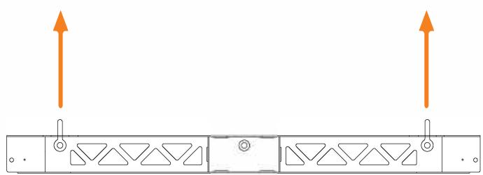
Use of two side lifting points. Recommended for an array greater than 8 modules, for a maximum of 12 modules.
DIMENSIONS


MR-T 218
Trolley
Code: 43897
Weight: 79.36 lb
Material: Steel
Max. 2 modules

DESCRIPTION
Transport trolley and use in ground stack configuration of up to 2 MYRA 218S modules
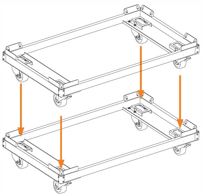
TO STACK THE TROLLEYS
- Position the trolley wheels so that they face inward.
- Align the wheels in the appropriate slots and stack
DIMENSIONS

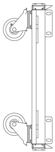

USING THE SHACKLES


ATTENTION: improper or incorrect usage of lifting accessories may generate a series of hazards, placing the operator, the personnel assigned to carry out the handling and lifting operations, the lifting equipment, personnel present in the vicinity, surrounding structures and objects and anything else that may be present with the radius of action of operations to be executed at the risk of serious injury and/or damage. Before carrying out any manoeuvres it is necessary to evaluate all the potential risks in order to avoid causing irreparable damage.
-The safety factor defines the degree of safety with respect to a product. While this value may be very high in certain cases, the maximum working load should not be exceeded under any circumstance, since this could result in serious damage and even breakages in extreme cases. The material from which a product is manufactured is also taken into account when calculating the safety factor. This means that the safety factor also indicates a certain degree of protection against phenomena such as wear and tear that may result from heavy-duty and continual usage.
-The following factors should be taken into account when selecting the shackles:
- Working load limit: the weight of the load suspended from the shackle must not exceed the recommended working load capacity of the shackle in question, as indicated clearly on the product.
- Coupling element: the shackle must be selected on the basis of the maximum force that may be exerted by the lifting cables, chains and/or accessories coupled to it.
- Working cycles: the shackles will continue to operate correctly as long as they retain their geometric and mechanical characteristics. Thus, depending on what they are to be used for, check the shackles for signs of wear and tear, and that they are coupled correctly with the cables, chains and/or accessories. Do not use any shackles that display signs of reduced cross section, deformation, squashing, bending, corrosion or instability with the coupling elements. Check the brackets for cuts, scoring, scratches, cracking, corrosion, sharp edges, and wear and tear resulting from improper use. Make sure that the pins do not display signs of bending, wear and tear, cuts or scoring, and that the thread is not damaged in any way; in the case of shackles with threaded pins, it must be possible to screw the pins in completely, without any irregularities; in the case of shackles with nuts and split pins, it must be possible to screw the nut all the way onto the pin without any irregularities, and the split pin must be present at all times. Do not use shackles with nuts and split pins where the nut and/or split pin is not present.


| LOAD ANGLE | SHACKLE EFFICIENCY |
| α = 0° | 100% working load |
| 0° < α < 45° | 70% working load |
| 45° ≤ α ≤ 90° | 50% working load |
The load must be applied to the shackle so that it is stable and the various components are perfectly aligned. The resulting force must always lie parallel to the main axis of the shackle body, perpendicular to the shackle pin. Avoid applying lateral loads as this reduces the efficiency of the significantly with respect to the working load.


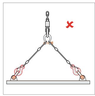


When moving loads using the shackles, ensure that the lifting elements are free to move and self-position; there must never be any strains or interference between the supporting elements and the load to be manoeuvred. Sudden, repeated application of weights that are close to the load bearing capacity, concentrated in a short space of time should be avoided as they may cause damage, deformation and, in extreme cases, failure and breakage. DO NOT exceed the maximum load capacity indicated on the body of the shackle under any circumstances.
When using a shackle to unite two lifting slings, always use a shackle with an omega type bracket to ensure that the lifting elements are seated correctly. The slings should be positioned on the bracket and not the pin.

ATTENTION: the tilt angle of the two slings, β , must never exceed 120° !
It is important to avoid applications where the movement (of the load or the lifting cable, for example) may cause the shackle pin to rotate, since this could cause it to unscrew, giving rise to hazardous situations, such as instability or even loss of load. Do not use different types of shackle pins or replace one type with another. Do not replace the shackle pins with common bolts or screws from a hardware shop!
Before carrying out any manoeuvres, make sure the shackle pin is fully tightened. Check that the shackle is coupled correctly with any cables, chains and/or other accessories. Check for any positioning errors. Pre-tension the entire lifting assembly and verify that each individual element is positioned and mounted correctly; once this has been done, apply the movement force so as to raise the load, slowly, linearly and constantly; avoid accelerating or decelerating abruptly as the load inertia could induce hazardous oscillations. The load should be set down in a pre-prepared area, with sufficient load-bearing capacity. Before releasing the tension on the slings, check that the load is positioned correctly and stable. Throughout the manoeuvre, the operator must remain in a position that guarantees a secure escape route in the event of an accident, i.e., he/she must remain at a safe distance from the load when in motion, while the entire area must remain off-limits to unauthorised personnel.
ATTENTION: incorrect or improper usage may result in serious injury to living creatures and/or damage to surrounding equipment.
Observations: do not use shackles on equipment for transporting personnel or animals; do not attempt to carry out repairs and, above all, welding on any type of shackle. Do not attempt to straighten bent or deformed sections. Checks and inspections: the shackles should be inspected once every three months (or more frequently in the case of particularly intensive usage) by suitably qualified personnel to ensure they are in _perfect working order.


USE OF PINS
- Press the button, the ball locking mechanism is deactivated
-
Release the button, the ball locking mechanism is activated
-
Insert the pin that must remain inside the hole
If the pin is inserted into two plates, the ball locking mechanism must pass through both plates and lock the pin
GROUND STACK & SUSPENDED ARRAY LIMITS
Safety limit: the safety limit indicates the maximum number of speakers that may be used in a single array, irrespective of the form, the angle of aperture and the number of suspension points.
Maximum limit: the maximum limit indicates the number of speakers that may be used in an array, in conformity with the specified safety factor; in this case, the form of the array, the angle of aperture and the number of suspension points must take into account the maximum permitted number; for this reason, always use a simulating software when calculating the safety factor relating to the mechanical suspension systems in use.

ATTENTION: it is also necessary to take the effect of the wind into account in the case of outdoor array configurations. The force exerted by the wind subjects the components of the suspended system to additional dynamic forces, giving rise to potentially hazardous situations.
In this case, it is necessary to monitor wind speed on a continuous basis, bearing mind that the greater the height above ground level, the higher the wind speed. The system suspension and retaining points must be designed to support the additional dynamic forces.
MYRA214L
Weight: 135.58 lb
Safe usage: 12 modules (safety factor 8:1)
Maximum load: 24 modules (safety factor 4:1)
Attention: when using more than 12 modules, check mechanical safety with the dedicated FBT MYRA Rigging Safety Calculator software.
MYRA218S
Weight: 192.90 lb
Safe usage: 6 modules (safety factor 8:1)
Maximum load: 12 modules (safety factor 4:1)
Attention: when using more than 12 modules, check mechanical safety with the dedicated FBT MYRA Rigging Safety Calculator software.
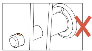
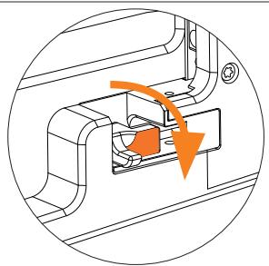
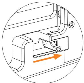
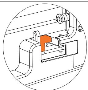
MYRA 214L modules are equipped with an angle locking mechanism that is activated automatically when the modules are suspended and reach their pre-selected angles of aperture. The mechanism consists of a quick-release pin identified by a red marking. The system is locked when the mechanism is inserted into the speaker.
N.B.: The locking mechanism is used to maintain the angle between the modules constant and avoid them assuming a different angle; the mechanism does not act as a supporting system, therefore it remains safe even if it is inadvertently left in the deactivated position.

UNLOCKED
ACTIVE
LOCKED

TRANSPORT AND ASSEMBLY
For the maximum transport of 4 MYRA 214L, the MR-T214 trolley is used; during this phase all the modules are set at an angle of 8°. To hook the modules, it is necessary to unlock, lift and position the rear flange of the trolley (fig. 1). Hook the module in the front and back on both sides by inserting the 4 locking pins (fig. 2).

ATTENTION: In transport mode the locking mechanism is deactivated (except in the first module attached to the trolley) (the red label must not appear).


TRANSPORT AND ASSEMBLY
Remove the pin on the front of the module, raise the flange and re-lock with the hooking pin, making sure that the front safety label is no longer visible (fig. 3.1).
Repeat the operation on the back of the module, locking the flange in the 8° position (fig.3.2).
Fig.3.2


Fig.3.1


TRANSPORT AND ASSEMBLY
Place up to a maximum of 4 modules.
FRONT FIXING: Block the modules together using the safety pin (fig. 4.1).
REAR FIXING:
Lift the pin of the graduated flange and fix the safety pin on 8° (fig. 4.2).
In this assembly phase make sure that the safety mechanisms of each added module have the red label clearly visible. (fig. 4.3).

ATTENTION: Make sure that all the fixing pins are correctly inserted.
During assembly the modules must always be set to 8° .

TRANSPORT AND ASSEMBLY
Greater stability is given by the MR-CT214 accessory (top cover), which is positioned on the highest module and which also allows, during shipping, a valid support for other equipment (fig. 6).
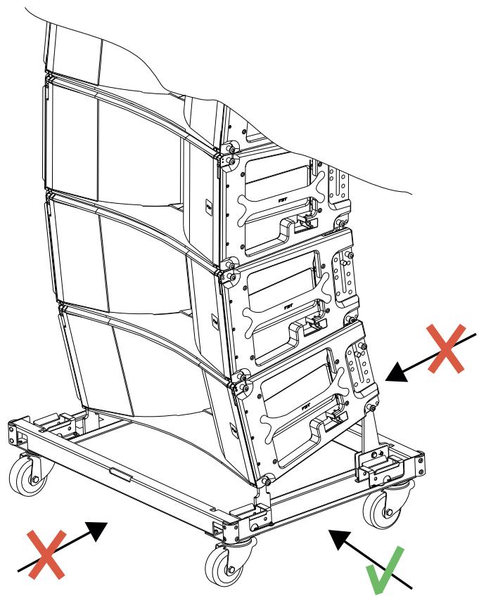
When transporting, avoid pushing the carriage in the front / back direction of the speakers; always act sideways to avoid overturning (fig. 7).

ATTENTION: During transport the modules must always be set at 8° .
Fig.6

Fig.7

ANGLE SELECTION
MYRA 214L modules are fitted with a lateral flange used to select the angle of aperture between the speakers; the colour scheme is designed to make it easier to select the various steps, which vary from 0.25° to 8° (fig. 8). The angles should always be selected when the modules are positioned on the transport trolley, so that the locking pins are not subjected to loading.
ANGLE SELECTION:
- Extract the safety pins from their initial position (8°)
- Select the desired angle by inserting the safety pin in the corresponding hole and activate the safety mechanism (fig. 9).
Fig.8


ATTENTION: insert all four safety pins to lock the stabiliser bars and fasten the safety cable in the corresponding hole.
UNLOCKE

ACTIVE

LOCKED


VERTICAL ARRAY
Attach the flybar to the first module using all four lateral fixing points and the 4° angle.

Make sure that all the locking pins have been inserted, that the module angles have been set-up correctly and that the safety locking mechanisms are in the correct position.
When the system is raised, each module will automatically assume the correct angle, at which point the safety lock is activated, locking the modules together at the preselected angle (Fig. 10).
Once the system has been raised slightly above ground level it is possible to detach the trolley.


When the array is raised, the safety mechanism is activated automatically, maintaining the preselected angle; at this point, the mechanism is fully inserted so that the red marking is no longer visible.

VERTICAL ARRAY
Repeat the previous operation (trolley plus 4 modules) to hook the second group of modules.
Align the two groups, carefully lower the first suspended group and proceed with the hooking through the four lateral fixing points (front and rear).

ATTENTION: After the installation phase, always check that the red labels are not visible on the safety mechanism

VERTICAL ARRAY
DE-RIGGING
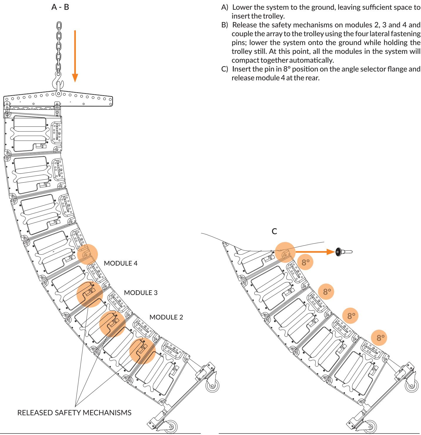
A) Lower the system to the ground, leaving sufficient space to insert the trolley.
B) Release the safety mechanisms on modules 2, 3 and 4 and couple the array to the trolley using the four lateral fastening pins; lower the system onto the ground while holding the trolley still. At this point, all the modules in the system will compact together automatically.
C) Insert the pin in 8° position on the angle selector flange and release module 4 at the rear.
VERTICAL ARRAY
DE-RIGGING
D) Slightly lift the structure, release the front fixing pin and move the four modules away from the trolley; repeat the operation for the rest of the system.


ANGLE SELECTION (USE)
MYRA 214L modules are fitted with a lateral flange used to select the angle of aperture between the speakers; the colour scheme is designed to make it easier to select the various steps, which vary from 0.25° to 8° . The angles should always be selected when the modules are positioned on the transport trolley, so that the locking pins are not subjected to loading.
ANGLE SELECTION:
- Extract the safety pins from their initial position (8°)
- Select the desired angle by inserting the safety pin in the corresponding hole and activate the safety mechanism.
Lowering the safety mechanism partially enables it; the red marking remains visible.
Manually lift one module at a time until the safety mechanism locks automatically (the red marking is no longer visible)
STORAGE & TRANSPORT
- Raise the modules manually one at a time (starting from the top) so as to unload the weight on the locking mechanism.
- Extract the locking mechanism and deactivate it
- Lower the module until it is compacted with the one beneath it


WARNING
CRUSH AZARD.
MIND YOUR
HANDS


- Extracting the locking mechanism without supporting the weight of the module causes the immediate closure of the two modules: TAKE PARTICULAR CARE TO AVOID INSERTING HANDS BETWEEN ONE MODULE AND ANOTHER DURING THIS PHASE


GROUND STACK
Ground stack installations must always be protected against movement, tipping and uneven ground. The maximum number of MYRA 214L modules that may be stacked is 4.
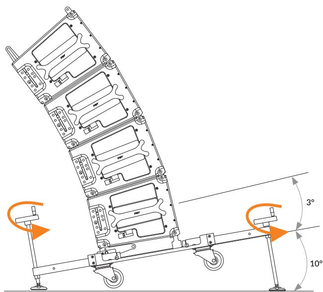
The MR-P214 accessory is a kit consisting of 4 adjustable feet and stabiliser bars that, in addition to ensuring the system remains stable when positioned on the ground, may also be used to regulate the tilt angle in the case of non-level surfaces.
The stabiliser bars are inserted in the corresponding slots on the MR-T214 trolley (fig. 1) and are equipped with several pairs of holes so that they may be used with various extensions; it is possible to correct negative or positive tilt angles of up to 10° by adjusting the regulator knobs (fig. 2).
!
CAUTION: Insert all four safety pins to lock the stabilizer rods and secure the safety cable.
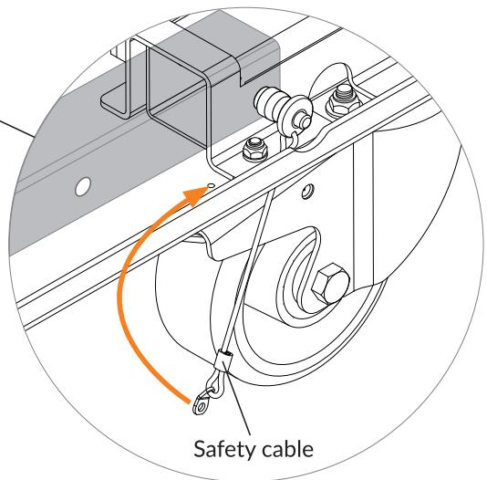

FIG.2
TRANSPORT AND ASSEMBLY
Use the MR-T218 trolley to transport the MYRA 218S modules (maximum 2 modules).
FASTENINGS BETWEEN TWO MYRA 218S MODULES
Slide the fastening pin to the left (fig. 1) until it exits the slider rail (fig. 2), raise the retractable locking mechanism and release the fastening pin (fig. 3).


VERTICAL ARRAY
The hook of the MR F218 flybar to the sub module is obtained simply by lifting the two lateral retractable mechanisms (A), then inserting the two safety pins.

TRANSPORT & STORAGE
Make sure that the system components are not subjected to mechanical stress or damaged when transporting them. Use suitable shipping cases.
MYRA system components are protected against humidity; however it is important to ensure all the components remain dry during storage, transportation and use.
VISUAL INSPECTION
- Visual inspection of the various mounting components for signs of damage (cracks, corrosion, etc.)
- Inspection of all mechanical parts, including the rear grills, to ensure they are fastened correctly.
- Lubricate the sockets at regular intervals using WD-40 or equivalent products.
SAFETY PIN
- Visual inspection of components for signs of deformation and corrosion.
• Inspection for damaged or missing ball bearings. - Functional test of the release mechanism to ensure it operates correctly.
- Lubricate the pins at regular intervals using WD-40 or equivalent products.
DISPOSAL
Damaged or unserviceable system components must be disposed of in accordance with the locally applicable environmental regulations.
Ensure that any damaged machine components are disposed of in such a way that they cannot be reused.

GENERAL INFORMATIONS
• MYRA rigging system manual
• Version: 1.1 ITA-EN / 11-2022 - Code 45748
- Keep this document in a safe place for future reference.
- Check the FBT website regularly for updates to this version.
- For correct use of the system, always consult the dedicated guides available from the FBT website on the pages corresponding to the product:
- MYRA 214L user manual
- MYRA 218S user manual
- MYRA Passive system preset and configuration
- For an accurate simulation of the system performance specifications the following software applications may be used:
- AFMG EASE FOCUS 3: Acoustic and aiming simulation, available for download from the website focus.afmg.eu
- GLL LIBRARY: Available for download from the FBT website for use in the EASE FOCUS 3 software
- MYRA RIGGING SAFETY CALCULATOR: Available for download from the FBT website
FBT Elettronica SpA - 62019 RECANATI (Italy) www.fbt.it - info@fbt.it

The MYRACK is designed as closed system rack providing mains power distribution and and connector interface for 3 x TALOS 20K4 T amplifiers each.
For this purpose, the Touring Rack is equipped with a mains power distribution device which also serves as a loudspeaker connector panel.
Also incorporated is an I/O panel which serves as a connector interface for both analog and digital audio signals as well as four network connectors for Ethernet remote capabilities.
Designed for workgroups and departments a Managed Switch with 24 RJ 45 ports that provides wire-speed performance is included.
The MYRACK working principle is entirely modular, so that the engineer can physically assemble and interconnect multiple elements to fit numerous applications. The MYRACK configuration based on a multiple of 3 TALOS 20K4 T yields the maximum flexibility and power resources.
Pursuant to Legislative Decree No. 49 of 14 March 2014 "Implementation of Directive 2012/19/EU on waste electrical and electronic equipment (WEEE)". The crossed-out bin symbol shown on the equipment indicates that the product at the end of its useful life must be collected separately from other waste. The user must, therefore, deliver the equipment intact with essential components that has reached the end of its life to the appropriate separate collection centers for electronic and electrotechnical waste, or return it to the dealer when purchasing new equipment of an equivalent type. Adequate differentiated collection for the subsequent start-up of the equipment sent for environmentally compatible recycling, treatment and disposal helps to avoid possible negative effects on the environment and on health and promotes the recycling of the materials of which the equipment is made. Illegal disposal of the product by the user involves the application of administrative sanctions pursuant to Legislative Decree No. 49 of 14 March 2014.

- AVVERTENZE
- MYRA 214L
- MYRA 218S
- AVVERTENZE DI INSTALLAZIONE
- MECCANISMO DI BLOCCO DELL'ANGOLO
- MR-FJ
- MR-T
- PER IMPILARE I CARRELLI TRA LORO
- RIGGING CLOSEUP
- MR-F
- DESCRIZIONE
- USO DEI GRILLI
- USO DEI PIN
- TRASPORTO E ASSEMBLAGGIO
- SELEZIONE ANGOLO
- ARRAY VERTICALE
- DE-RIGGING
- GROUND STACK
- TRASPORTO/STOCCAGGIO
- INSTALLATION INSTRUCTIONS
- ANGLE LOCK MECHANISM
- MYRA 214L INSTALLATION
- MYRA 218S INSTALLATION
- CARE AND MAINTENANCE
- SAFETY
- INFORMATION NOTES
- FLYBAR MR-F
- MR-F 214 CONFIGURATIONS
- EXTENSION BAR AND FRAME ORIENTATION
- CAUTION
- DIMENSIONS
- TO STACK THE TROLLEYS
- DESCRIPTION
- MR-F 218 CONFIGURATIONS
- USING THE SHACKLES
- USE OF PINS
- GROUND STACK & SUSPENDED ARRAY LIMITS
- MYRA214L
- MYRA218S
- TRANSPORT AND ASSEMBLY
- REAR FIXING
- ANGLE SELECTION
- VERTICAL ARRAY
- ANGLE SELECTION (USE)
- STORAGE & TRANSPORT
- FASTENINGS BETWEEN TWO MYRA 218S MODULES
- TRANSPORT & STORAGE
- VISUAL INSPECTION
- SAFETY PIN
- DISPOSAL
- GENERAL INFORMATIONS
Brand : FBT
Model : MYRA (systeme d'accroche)
Category : Speaker