FRM GTO2 UP - Professional audio system Outline - Free user manual and instructions
Find the device manual for free FRM GTO2 UP Outline in PDF.
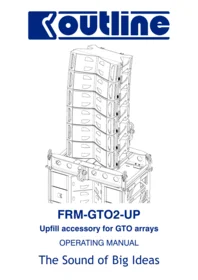


| Product Type | Upfill accessory for GTO loudspeaker arrays |
| Brand | Outline |
| Model | FRM GTO2 UP |
| Compatible Bumpers | FRM-GTO and FRM-GTO2 |
| Compatible Loudspeakers | Mantas and Butterfly High-pack (CDH 483) |
| Maximum Array Elements | 6 loudspeakers |
| Maximum Supported Load | 204 kg (449 lbs) |
| Angle Adjustment Range | 0° (level with bumper) to 3° upward |
| Mounting Hardware Included | 8 x M10 bolts (min. 30 mm / 1" 1/4), 8 x M10 nuts, 16 washers |
| Included Parts | 2 supports (M WLD 105, M WLD 106), 2 bars, 2 pins, 2 spring cotters |
| Primary Function | Forms up-fill clusters on top of flying bumper for enhanced coverage |
| Safety Requirement | Install with at least three hanging points and a counterweight GTO element |
| Safety Check | Verify safety latches on side links are engaged after each connection |
| Maintenance | Periodically inspect all mechanical connections and rigging components |
| Construction | High-quality steel components for professional touring use |
| Standards | CE compliant with European Machinery, EMC, and Low Voltage directives |
| Country of Manufacture | Italy |
| Manual Reference | Z OMFRM-GTO2-UP |
Frequently Asked Questions - FRM GTO2 UP Outline
User questions about FRM GTO2 UP Outline
0 question about this device. Answer the ones you know or ask your own.
Ask a new question about this device
Download the instructions for your Professional audio system in PDF format for free! Find your manual FRM GTO2 UP - Outline and take your electronic device back in hand. On this page are published all the documents necessary for the use of your device. FRM GTO2 UP by Outline.
USER MANUAL FRM GTO2 UP Outline
FRM-GTO2-UP
Upfill accessory for GTO arrays
OPERATING MANUAL
The Sound of Big Ideas
NORME DI SICUREZZA / SAFETY REGULATIONS
In order to avoid risks for the user's and other people's safety, as well as annulling the warranty, it is advisable to read the suggestions in this section for correct use of the product.
This unit was designed as part of a sound reinforcement or audio recording system.
Any use other than that foreseen by the manufacturer is carried out under the sole responsibility of the user.
- Do not expose the unit to rain and don't use it in locations with a high humidity level.
- Do not allow any type of liquid or solid object to enter the unit; should this occur, stop using the unit and contact OUTLINE or specialist staff.
- The mains power cable is supplied without a plug, to enable it to be connected according to current standards in the country of use, or according to the requirements of the specific situation. ALWAYS carry out connections following the correct procedure.
- When connecting the unit, ALWAYS check ground connection as required by technical and safety norms.
- If the original cable is worn or damaged, it must be replaced with another of the same type (in perfect condition).
- Make sure that the supply voltage corresponds to the selected value on the panel connections
- Carry out connections in an orderly fashion, only allowing access to this procedure to expert staff.
- The unit must only be switched on after having connected and switched on all the other components of the sound reinforcement/recording system, to avoid annoying noises that can sometimes damage the loudspeakers.
- The unit must only be moved when the cables are disconnected.
- Only dedicated accessories, specifically designed for the system, or any standard accessories foreseen may be used when installing.
- The mechanical operation of the product and the accessories used must be checked periodically.
- This unit produces high sound pressure levels that can damage hearing if listened to under incorrect conditions.
- The unit must only be opened and/or repaired by specialist staff.
- For any requirements of a technical nature, contact OUTLINE or authorized staff.
SMALTIMENTO RIFIUTI / DISPOSAL OF WASTE MATERIALS

Your product is designed and manufactured with highly quality material and components, which can be recycled and reused. When this crossed-out wheeled bin symbol is attached to a product, it means the product is covered by the European Directive 2002/96/EC and subsequent amendment 2003/108/EC. Please inform yourself about the local separate collection system for electrical and electronic products. Please act according to your local rules and do not dispose your old products with your normal household waste. The correct disposal of your old product will help prevent potential negative consequences for the environment and human health.

* COMFORMITY
*European Community
All the Outline electroacoustic and electronic devices are in accordance with the objects stated by the CEE directives reported at the end of this manual.
The “FRM-GTO-2-UP” assembly is an accessory for the GTO system’s flying bumper and is used to form small arrays of loudspeakers on its top, for “up-fill” duties.
• Compatible Bumpers: FRM-GTO e FRM-GTO2.
- Compatible Loudspeakers: Mantas e Butterfly High-pack (CDH 483).
• Maximum number of elements: 6 (204 kg).
Parts description
The “FRM-GTO-2-UP” assembly is made of:
- two supports (M WLD 105 and M WLD 106) which have to be connected to the flying bumper;
- a pair consisting of a bar, one pin and a spring cotter that has to be conencted to the first element of the “up-fill” cluster.
- the fastening system consists of eight M10 bolts (minimum length: 30 mm, or 1" 1/4), eight M10 nuts and sixteen washers.
Forbidden use
The system must be used according to the instructions provided. Any other use is FORBIDDEN.
Never exceed the stated limits, both in terms of maximum weight, number and type of elements.
Selecting the angle for the first cabinet
The angle of the first box is selectable by putting the mobile bar inside the support and the pin in the corresponding hole. The available angles are from 0° (same bumper angle) to 3° upward.
CAUTION:
In order to minimize the roll-over risk, it is NECESSARY to hang the bumper from at least three points (two on the front and one on the rear) and connect at least one GTO element underneath the bumper, as a counterweight.


ISTRUZIONI DI MONTAGGIO / INSTRUCTIONS
1) Connessione al frame
1) Bumper connection
After choosing the frame position, connect the two elements on the top of the bumper on its backside, using the M10 screws, nuts and washers.
If you are using Mantas loudspeakers, in order to simplify the following mounting steps, place the supports with the labels towards the inside the frame. Otherwise, if you are using Butterfly loudspeakers, towards the outside.
Check the alignment of the two blocks with the structure, push them towards the bumper's rear in order to ensure that the bolts are properly located within their respective holes.
Tighten each bolt via two adequate wrenches (17 mm or 11/16").


Blocks' labels towards the inside when using Mantas.
Blocks' labels towards the outside when using Butterfly.
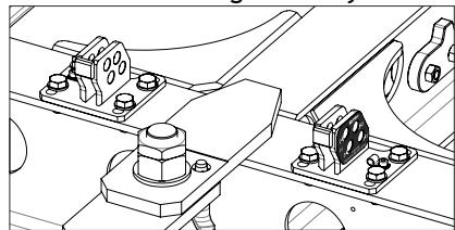
Select the angle for the first loudspeaker and place the two bars towards the block's back, as indicated in the following picture, in order to not interfere with the next steps.
Check that both bars are set to the same angle.

ISTRUZIONI DI MONTAGGIO / INSTRUCTIONS
3) Front connection of the first loudspeaker.
Put the first loudspeaker on the frame, align its side hardware with the corresponding hole on the bumper's crossbeam.
Insert the side links, as normally used during the normal Mantas and Butterfly rigging.
Check that the loudspeaker is well-placed and that the safety latch is in the normal working position for each side.

4) Rear connection of the first loudspeaker.
Unlock and pull one of the two pins on the loudspeaker's back, rotate the box in order to place the mobile bar and release the pin.
Repeat the step on the other side.
Check that the system is stable.

ISTRUZIONI DI MONTAGGIO / INSTRUCTIONS
5) Preparation for the following connection.
Retract only half-way one of the two back pins and insert the link bar with the correct pre-selected angle.
Repeat the step on the other side.
Check that the two bars have the same angle set.

6) Front connection of the second loudspeaker.
Place the second loudspeaker on the first one aligning the side hardware.
Insert the lateral bars on both sides.
Check that the loudspeaker is well-placed and that the safety latch is in the normal working position for each side.

ISTRUZIONI DI MONTAGGIO / INSTRUCTIONS
7) Rear connection of the second loudspeaker.
Unlock and pull one of the two pins on the loudspeaker's back, rotate the box in order to place the rear angle bar and release the pin.

Repeat the steps from 5 to 7 for all the following boxes, in order to set up the complete system (maximum six loudspeakers), respecting the splay angles defined in the project.

CODICI RICAMBI / SPARE PART CODES

NOTE
The standard hardware is not reported in this scheme.
The fastening system to the bumper consists of eight M10 bolts (minimum length: 30 mm, or 1" 1/4), eight M10 nuts and sixteen washers.
Outline carries out on-going research for product improvement. New materials, manufacturing methods and design upgrades are introduced to existing products without prior notice as a routine result of this philosophy. For this reason, any current Outline product may differ is some aspect from its description, but will always equal or exceed the original design specifications unless otherwise stated.
© Outline 2013
Operating manual product code: Z OMFRM-GTO2-UP
Release: 040213
Printed in Italy
Outline
CE DECLARATION OF CONFORMITY
The company
Outline s.r.l.
Via Leonardo da Vinci, 56
25020 Flero (Brescia) – Italy
declares under its sole responsibility that all electro-acoustic and electronic audio low frequency professional products, speakers components and loudspeakers included, are manufactured in ITALY in according with objects stated by below CEE (where applicable):
- Directive 2006/42/CE of 17th May 2006 "Machinery Directive", published in the Official Gazette - issue 331 of 07.12.1998.
- Legislative Decree 17 of 27/01/10, "Implementation of Directive 2006/42/CE regarding machinery, and which modifies directive 95/16/CE regarding lifts (elevators)";
- Legislative Decree 81 of 9/04/08, "Implementation of Art. 1 of law N° 123 of 3/08/07 on the matter of safeguarding health and safety in workplaces" and later amendments regarding the improvement of safety and health of workers in workplaces;
• Directive 2006/95/CE, "Low Voltage"; - Directive 2004/108/CE, "Electromagnetic Compatibility";
- Directive 2003/10/CE (Legislative Decree 195/06), "Protection from noise";
• Legislative Decree 195 of 10/04/06, “Implementation of Directive 2003/10/CE regarding the exposure of workers to risks arising from physical agents (noise)”; - UNI EN ISO 12100 (2010), "Safety for machinery - General principles for design – Risk assessment and risk reduction";
- UNI EN 13857 (2008), "Safety of machinery -- Safety distances to prevent hazard zones being reached by upper and lower limbs";
- UNI EN 349 (2008), "Safety of machinery - minimum gaps to avoid crushing of parts of the human body";
- UNI EN ISO 13850 (2008), "Safety for machinery - Emergency stop - Principles for design";
- UNI EN 614-1 (2009), "Safety of machinery - Ergonomic design principles - Part 1: Terminology and general principles";
- UNI EN 614-2 (2009), "Safety of machinery - Ergonomic design principles - Interaction between machinery design and work tasks";
- UNI EN 894-1 (2009), "Safety of machinery - Ergonomics requirements for the design of displays and control actuators - General principles for human interactions with displays and control actuators";
- UNI EN 894-2 (2009), "Safety of machinery - Ergonomics requirements for the design of displays and control actuators – Displays";
- UNI EN 894-3 (2009), "Safety of machinery - Ergonomics requirements for the design of displays and control actuators – Control actuators";
- UNI EN 953 (2009), "Safety of machinery – Guards - General requirements for the design and construction of fixed and movable guards";
- UNI EN 981 (2009), "Safety of machinery - Systems of auditory and visual danger and information signals"
- UNI EN ISO 13849-1 (2008) "Safety of machinery – Safety-related parts of control systems – Part 1: General principles for design";
- UNI EN ISO 13855 (2010) "Safety of machinery - Positioning of protective equipment with respect to the approach speeds of parts of the human body"
- UNI EN 1037 (2008), "Safety of machinery – Prevention of unexpected start-up";
- UNI EN 1760-2 (2009), "Safety of machinery - Pressure sensitive protective devices - Part 2: General principles for the design and testing of pressure sensitive edges".
- UNI EN ISO 4871 (2009) "Acoustics — Declaration and verification of noise emission values of machinery and equipment";
- CEI EN 60204-1 (2006), (CEI 44-5), "Safety of machinery - Electrical equipment of machines - Part 1: General rules";
- CEI EN 60947-1 (2008), (CEI 17-44), "Low-voltage switchgear and control gear - Part 1: General rules";
- CEI EN 60446 (2008), (CEI 16-4), "Basic and safety principles for man-machine interface, marking and identification - Identification of conductors by colours or alphanumerics";
- CEI EN 61310-1 (2008), (CEI 44-5), "Safety of machinery - Indication, marking and actuation - Part 1: Requirements for visual, acoustic and tactile signals";
- CEI EN 61310-2 (2008), (CEI 44-5), "Safety of machinery - Indication, marking and actuation - Part 2: Requirements for marking";
- UNI EN 1990 (2006), "Eurocode - General structural design criteria";
- UNI EN 1991-1-1 (2004), "Eurocode 1 – Actions on structures - Part 1-1: General actions – Densities, self-weight and imposed loads for buildings"
- UNI EN 1993-1-1 (2005), "Eurocode 3 - Design of steel structures – Part 1-1: General rules and rules for buildings"


- FRM-GTO2-UP
- NORME DI SICUREZZA / SAFETY REGULATIONS
- SMALTIMENTO RIFIUTI / DISPOSAL OF WASTE MATERIALS
- PARTS DESCRIPTION
- FORBIDDEN USE
- SELECTING THE ANGLE FOR THE FIRST CABINET
- CAUTION
- ISTRUZIONI DI MONTAGGIO / INSTRUCTIONS
- CONNESSIONE AL FRAME
- BUMPER CONNECTION
- FRONT CONNECTION OF THE FIRST LOUDSPEAKER
- REAR CONNECTION OF THE FIRST LOUDSPEAKER
- PREPARATION FOR THE FOLLOWING CONNECTION
- FRONT CONNECTION OF THE SECOND LOUDSPEAKER
- REAR CONNECTION OF THE SECOND LOUDSPEAKER
- NOTE
- OUTLINE
- CE DECLARATION OF CONFORMITY
- THE COMPANY
Brand : Outline
Model : FRM GTO2 UP
Category : Professional audio system