SUPERFLY - Speaker Outline - Free user manual and instructions
Find the device manual for free SUPERFLY Outline in PDF.


| Product Type | Professional Line Array Loudspeaker |
| Brand / Model | Outline / SUPERFLY |
| System Configuration | 3-way active, quad-amplified system |
| Frequency Response | 50 Hz - 20 kHz (-10 dB) |
| Horizontal Dispersion | 90° |
| Vertical Dispersion | Array-dependent, adjustable splay angles |
| Splay Angles | 0° to 7.5° in 0.5° steps, plus 0.25° precision setting |
| Low-Frequency Drivers | 2 x 10" neodymium woofers, double reflex band-pass loaded |
| Midrange Drivers | 2 x 8" neodymium woofers, partially horn-loaded hybrid band-pass |
| High-Frequency Driver | 1 x 3" diaphragm compression driver with D.P.R.W.G. waveguide |
| Nominal Impedance | Low: 2 x 16 Ω, Mid: 16 Ω, High: 16 Ω |
| Power Handling (AES) | LF: 2 x 450 W continuous / 1800 W peak; MF: 400 W / 1600 W; HF: 120 W / 480 W |
| Maximum SPL | 143 dB single box, 155 dB four-box array |
| Connectors | 2 x LKI8 8-pin military-grade parallel |
| Cabinet Material | Baltic birch plywood |
| Cabinet Finish | Black polyurea coating |
| Rigging | Integrated high-load aluminium hardware, quick-lock steel pins |
| Weather Resistance | Rainproof with polyurea coating |
| Dimensions (H x W x D) | 239 x 909 x 636 mm (278 x 909 x 636 mm with rigging) |
| Weight | 38 kg (83.8 lb) |
| Maintenance | Periodic checks of cables, connectors, transducers and mechanical parts required |
| Spare Parts | Woofers, compression driver diaphragm, ferrofluid kit available |
| Disposal | Complies with EU Directive 2012/19/EU; do not dispose as household waste |
Frequently Asked Questions - SUPERFLY Outline
User questions about SUPERFLY Outline
0 question about this device. Answer the ones you know or ask your own.
Ask a new question about this device
Download the instructions for your Speaker in PDF format for free! Find your manual SUPERFLY - Outline and take your electronic device back in hand. On this page are published all the documents necessary for the use of your device. SUPERFLY by Outline.
USER MANUAL SUPERFLY Outline
SUPERFLY
Advanced Loudspeaker Concept

CONTENTS
1. SAFETY INSTRUCTIONS....3
1.1. DISPOSIZIONI PER LO SMALTIMENTO 3
1.2. CONFORMITA' E GARANZIA....3
2. DESCRIPTION OF THE SYSTEM ....4
3. ADVANTAGES OF LINE ARRAY CONFIGURATION....6
4. CABLING 8
4.1. CONNECTOR SPECIFICATIONS.... 10
4.2. CABLES AND ILLUSTRATIONS 11
5. AMPLIFICATION....13
6. SUPERFLY PRESET....15
6.1. AVAILABLE PRESETS.... 15
7. OPEN ARRAY 2 AND AIMING....16
8. ADDITIONAL ELEMENTS......17
8.1. DBS 18-2 SUBWOOFER....17
8.2. MANTAS 28 DOWNFILL 18
9. ALIGNMENT AND TUNING....19
10. RAPID CHECKS : FASTQC-LS 20
11. CHECKS 21
11.1. OPERATING INSPECTIONS/TESTS....21
11.2. PERIODIC CHECKS 22
12. SPARES....23
13. TECHNICAL CHARACTERISTICS ....25
APPENDIX A: PERIODIC INSPECTION TABLE....27
1. SAFETY INSTRUCTIONS
Welcome to the Outline World!
Congratulations for having chosen Superfly as your sound system. We suggest you dedicate some time to reading this manual in order to get to know this product in depth and ensure you make the most of its use.
It is important to remain at a suitable distance from the sound reinforcement system, particularly when it is used at high spl.
The Superfly system is designed for sound reinforcement in medium-large sized venues and, due to its performance, could cause hearing damage.
Safety precautions to be adopted are as follows:
- for all the information regarding the actual installation of the system (rigging, derigging and all related matters) the “Superfly / Mantas 28 Rigging Manual” must be consulted;
- for installation, the staff involved must know and be familiar with the safety procedure to follow in these situations;
- it is absolutely inadvisable to use material, cables, amplifiers, acoustic prediction software or anything else that is not expressly foreseen by Outline.
Outline declines any and all responsibility for damage or faulty operation caused by using the Superfly system in a different way from that expressly foreseen and specified:
- uncertified or unauthorized modification to any part of the system can damage the system, compromising its real efficiency and safety;
- it is advisable to carry out periodic inspections/checks and any necessary maintenance of the systems, cables and the amplifiers before using them. In the event of wear or accidental damage of the components, Outline will provide specific support for their replacement (chap. 11);
- frequently check the conditions and correct operation of the mechanical parts (details are to be found in the “Superfly / Mantas 28 Rigging Manual”).
Since the system is equipped with loudspeakers/transducers that produce a static magnetic field, it is strongly advisable to keep any electronic devices or magnetic media of any type (computers, hard disks, magnetic card, etc) at a suitable distance (approximately 1 metre) from the loudspeakers.
1.1. INSTRUCTIONS FOR DISPOSAL

The product is designed and manufactured with high quality materials and components, which can be recycled and reused. When this symbol of the crossed “wheelie” bin is attached to a product, it means that the product is covered by the European Directive 2012/19/EU and successive amendments. This means that the product must NOT be disposed of with other household-type waste.
Users are responsible for the disposal of their electric and electronic equipment, consigning it to an approved disposal facility. For further information on where it is possible to send equipment for recycling, contact your local distributor. Correct disposal of the old product will help to prevent potential negative consequences for the environment and people's health.
1.2. COMPLIANCE AND GUARANTEE

All Outline electro-acoustic and electronic devices are in conformity with the provisions of EC/EU directives (as stated in our CE declaration of conformity).
The CE declaration of conformity is attached to the product warranty certificate and is shipped with the product.
2. DESCRIPTION OF THE SYSTEM

As in all Outline products, every single component, the cabinet and relative dimensions, are the result of accurate choices following specific studies based on the idea of the design of the element in question, regarding its use as part of a complete system.
Superfly is a three-section active system with no passive crossover filter and fitted with:
- two 10 "" woofers with double reflex (band-pass) loading for the low frequency section (two separate amplification channels);
- two 8" mid-woofers coupled with band-pass hybrid loading with partially horn-loaded output for the mid frequencies (one amplification channel);
- a compression driver with a 3" diaphragm, coupled with a D.P.R.W.G. waveguide, and a constant directivity horn for accurate horizontal dispersion control for the high frequency section (one amplification channel).
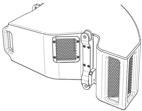
The cabinet is constructed Baltic birch plywood and undergoes a precise assembly process: some parts are made with curved wood, whereas other sections are formed from appropriately shaped panels. This enables to obtain a very rigid cabinet without any internal resonance. Useful external handles are fitted to facilitate handling and installation to the utmost. The material used, along with the polyurea coating, enables the system to be used even in the event of rain.
The flying hardware is built into the cabinet's structure: the side bars are fixed, whereas the rear ones have moveable elements that enable to set the flying angle. All bars are manufactured in anodized aluminium alloy to ensure that they are light-weight and long-lasting, whereas the quick-locking pins are in steel and ensure anchorage. Rigging instructions are contained in the “Superfly / Mantas 28 Rigging Manual”.
A particularity of the Superfly is its application of SART (Side Acoustic Rejection Technology), which consists in the particular acoustic structure of the LF section, specifically designed to concentrate the low frequencies' energy on the sound projection axis and minimize side emission.
This enables to achieve improved horizontal dispersion control, thanks to which considerable benefits will be obtained, for example, on particularly reverberant stages and/or venues where acoustic energy dispersed outside the required coverage area would cause several problems.

One of Superfly's strong points is its wide frequency response, from 50 Hz to 20 kHz. This enables to obtain:
- the extended bottom end of the low frequencies, even without dedicated subwoofers, makes the Superfly system truly “self-sufficient” for a large number of situations;
- powerful controlled emission of the mid frequencies, thanks to the exploitation of the external portion of the horn, shared with the high frequency section;
- a long coherent throw up to the highest frequencies, thanks to the use of a D.P.R.W.G, waveguide, which is also loaded by the constant directivity horn that controls horizontal dispersion for the entire frequency range emitted by the MF and HF sections.

D.P.R.W.G. concept
3. ADVANTAGES OF LINE ARRAY CONFIGURATION

Superfly: horizontal isobar plot

Superfly: vertical isobar plot
As well as its excellent control of horizontal directivity, Superfly ensures flexible control of directivity on the vertical plane thanks to the precision of its D.P.R.W.G. waveguide and the possibility of being able to geometrically configure the array according to the needs of the area to be covered: splay angles are available from 0° to 7.5° in steps of 0.5° , plus an additional 0.25° setting for the utmost precision with long-throw aiming.
Thanks to the mutual coupling, the level of the mid-low and low frequencies will also increase according to the length of the array.
This is why the frequency response of the single elements and the power handling of the individual sections have been designed for optimum operation of the entire array.
If no or few dedicated subwoofers are available, this can be very useful for overall sound reinforcement, combined with the wide-ranging performance of Superfly's low frequency section.
On the right, a series of simulations carried out with OpenArray2 in which various effects of mutual coupling for arrays made up of 8, 12 and 16 elements are highlighted. It can be seen how the factory preset results in acoustic balance in the first case of the array of 8 elements, while in the other two cases it will be necessary to carry out compensation in order to obtain acoustic balance again.


n.8 Superfly array elements @15 m

n.12 Superfly array elements @15 m

n.16 Superfly array elements @15 m
The effect can therefore be almost completely compensated, according to taste, requirements and venues' particular acoustic characteristics, modifying the system's equalization as seen in the illustration alongside (example of EQ via Outline Newton processor).
It is advisable to use a low-shelving filter with a centre frequency of between 400 Hz and 500 Hz, ample width and gain that is variable by -6 dB when the number of elements is doubled, modifiable according to requirements.

The low frequency section, thanks to the coupling of adjacent sources and the geometric extension of the entire array, has the benefit of greater directivity control: greater control of the directivity of the low frequencies will be obtained as the array's effective length increases.


These simulations, carried out with OpenArray2, confirm how the use of just 4 array elements gives no advantage as far as vertical directivity and sound reinforcement on the mid-low frequencies (125 Hz – 500 Hz) are concerned, with the same measurement distance (15 m). On the other hand, when 8 or more elements are used, the effects and advantages of mutual coupling become clear and easily predictable.


4. CABLING
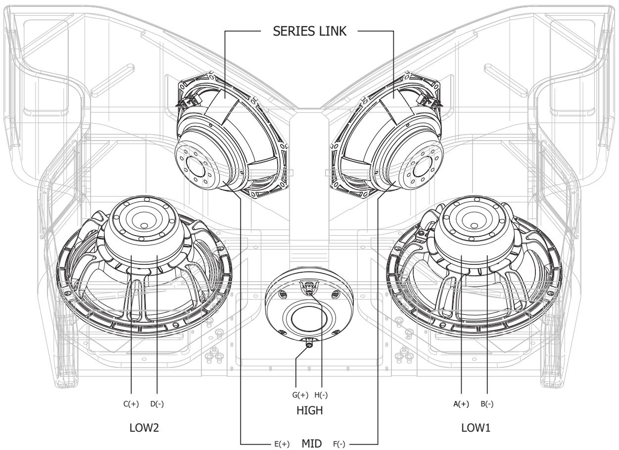
Superfly requires LK8 cables, compatible with the 8-pole connectors on his panel:
• A[+] / B[-] → LOW1
• C[+] / D[-] → LOW2
• E[+] / F[-] → MID
• G[+]/H[-] → HIGH

It is important to periodically check the conditions of the cables and connectors, as they carry voltage that is potentially dangerous in the event of coming into direct contact with parts of the body.
These checks are also carried out to prevent any damage to the components and amplifiers, and above all to avoid faulty system operation.

The nominal impedance is 16 Ohms for each if the four power channels. This enables to connect up to a maximum of four elements in parallel on the same number of amplification channels, thus obtaining optimum energy transfer from the amplifiers to the sound system.
The components' electroacoustic characteristics are therefore sized coherently with the aforementioned criteria to obtain maximum dynamic performance from the array, while also ensuring conditions of extreme reliability and very low distortion.
4.1. CONNECTOR SPECIFICATIONS
The model used for the cabling of elements such as Superfly, is the LKi8MF-25 cable (male/female 8-pin). Its standard length of 25 m is ideal for the cabling of arrays flown at a considerable height. However, by means of a specific adaptor, it is possible to create an extension by connecting two or more cables of this type.
The LKi8MF-0.9 cable on the other hand is only for linking array elements (male/female 8 pin, length 0.9 m). Further details can be found in the diagram in chap. 4.2.
As far as connectors' wiring is concerned, it is sufficient to follow the following diagram (identical for all Outline products with this type of connector):
LKi8MF cable setting

A second model, used by some specific Outline elements, is the SP2-LKi8 cable. This enables to cable elements such as front fill speakers, down fill enclosures, etc. (see chap. 8.2) fitted with speakON NL4 connectors, with the same panels of the amplifier
racks used for Superfly (see chap. 5).
For elements such as Outline DBS 18-2 subwoofers (see chap. 8.1) SP4 LKi8 cables are foreseen, which have 4 speakON NL4, of which 2 are in parallel:
SP2 LKi8 cable setting

SP4 LKi8 cable setting
4.2. CABLES AND ILLUSTRATIONS
| CODE | DESCRIPTION | |
 | LKI8MF-25 | 25 m loudspeaker cable (male/female, 8 poles x 4 mm2) |
 | LKI8MF-0.9 | 0,9 m loudspeaker cable (male/female, 8 poles x 4 mm2) |
 | SP2 LKI8-15 | 15 m loudspeaker cable (8 poles x 4 mm2) with LKI8/2 speakon connectors |
 | SP2 LKI8-25 | 25 m loudspeaker cable (8 poles x 4 mm2) with LKI8/2 speakon connectors |
 | SP4 LKI8-11 | 10 m subwoofer cable (8 poles x 4 mm2) with LKI8/4 speakon connectors |
 | SSVLKI8MF | Male/female adaptor for LKI8 cables |
  | MPULK-3X8 | 3U Distro unit, 5 poles 32 A line mains plug 3TH+N+E, 6xLK8 loudspeaker sockets for #3 X8 power amplifiers |
 | CABLA1-0X8 | 2U Distro unit, 2 x LK8 loudspeaker sockets, 8x Speakon for 0X8 power amplifiers |
5. AMPLIFICATION
For the use of Superfly and relative additional products (subwoofers, front fills, etc.) the X8 amplifier was selected, which, thanks to its on-board DSP, enables simple accurate management of each section of the audio system. The key data are shown in the following table.
X8 is an 8-channel amplifier with 8 analogue inputs, AES3 and Dante (optional). Control is via Ethernet and power can be single phase, two-phase and three-phase. For the installation and use of these amplifiers, refer to the relative manuals.
| Output power | Single channel mode | Bridge mode | |||
| 2 Ω | 4 Ω | 8 Ω | 4 Ω | 8 Ω | |
| 5200 W | 3000 W | 1600 W | 10400W | 6000W | |
| Max output voltage / current | 175 Vpeak / 130 Apeak | ||||
Outline also has a series of accessories (panels, cables, racks) to ensure rapid error-proof use of Superfly with these amplifiers.
Two types of amp rack are foreseen, according to requirements: Out-rack A (fitted with an X8 amplifier) and Out-rack B (fitted with three X8 amplifiers). These are used in the various configuration kits available.

Out-rack A:
• 4 RU rack designed to be highly resistant to impacts;
- Panel CABLA1-OX8 for audio cabling with 2 LK8 connectors (8 channels), 4 speakON connectors for biamped systems and 8 speakON connectors for elements requiring just one amplification channel;
- An X8 amplifier with on-board digital signal processor (DSP), optional Dante and remote control.


Out-rack B:
• 12 RU wheel-mounted rack, designed to be highly resistant to impacts;
- A MPULK-3X8 panel for audio cabling with 6 LK8 connectors (12 channels) and 32 A / 400 V (3P+N+G) electrical connection, with thermal magnetic circuit breaker;
- CABLA1-GTO panel for signal cabling with 2 analogue input channels and link, 2 AES3 digital input channels and link and two Ethernet ports (etherCON connector);
- Three X8 amplifiers with on-board digital signal processor (DSP), optional Dante and remote control.
In the kits proposed by Outline there is also an Outline Newton processor, which provides immediate management of all the parts of the audio system in addition to the on-board functions of the X8 amplifiers' DSP. For further info: newton.outline.it

6. SUPERFLY PRESET
Armonía Plus, the X8 amplifiers' management software, includes presets for optimum use of Superfly and relative elements. Using it, it is possible to upload the presets for each component of the audio system and have control of parameters such as levels, delay, polarity and input EQ for each element or for groups.
On the armonia.powersoft.it web site it is possible to download this software and find all the instructions and training courses for its use.

6.1. AVAILABLE PRESETS
Superfly requires dedicated presets for the control of its four sections. These settings are intended as enclosure presets, i.e. enable to upload in the correct order and all with one operation the settings of the four sections, following the standard used in the cabling panels. The order of the sections is: mid, high, low1, low2.
In particular two presets are available: the first regards full-range use, i.e. without subwoofer, and is characterized by a filter high-pass a 55 Hz (Superfly HP55); the second regards use with subwoofer and has a high-pass filter a 70 Hz (Superfly HP70).

Outline decline any responsibility in the case of use of settings other than the official ones provided by Outline, as these would involve risks for the sound system.
7. OPEN ARRAY 2 AND AIMING
As anticipated, OpenArray2 software enables to obtain a clear prediction of sound coverage achievable by the Outline system chosen for any given event or permanent installation. More specifically, as well as the effects of mutual coupling already mentioned, the software is able to offer an overview of what will be the best choice of aiming of the system with respect to the area to be covered, considering all its variations: number of elements, ground stacks or flown arrays, position and height of the array, angle of the array, splay angle of the elements, electronic parameters (gain, polarity, delay), simulation of the frequency response in various points of the audience area.

OpenArray2 will provide reliable prediction, always to be considered in the direct field. It is obviously important to remember that the final acoustic results obtained once the system is installed on-site can vary according to the various contexts and locations of use (open spaces, acoustically treated indoor venues, particularly reverberating ones, etc.). So it is possible to consider the eventuality of modifying the design, providing the safety parameters imposed by OpenArray2 are respected. All the details can be found in the "Superfly / Mantas 28 Rigging Manual".

8. ADDITIONAL ELEMENTS
8.1. DBS 18-2 SUBWOOFER

In spite of Superfly's great potential on low frequencies, in certain circumstances (large tours, festivals or events) the use of subwoofers is inevitable. To meet this requirement, Outline conceived and designed the DBS 18-2.
Thus system with double 18" woofers (28 Hz - 160 Hz), uses cabling with an NL4 connector (1+/1- LF1; 2+/2- LF2), connectable to the CABLA1-OX8 panel via 4-pole cables with speakON connectors, or via SP4-LK8 cables (with an LK8 connector at one end and four speakON connectors at the other). With the MPULK-3X8 panel SP4-LK8 cables must be used.
For use with Superfly, a specific preset is foreseen for X8, which is part of the Superfly "family".
DBS 18-2 us also available in a flyable version with built-in connecting hardware and LK8 connectors (GTO-SUB).
Further details on www.outline.it

8.2. MANTAS 28 DOWNFILL
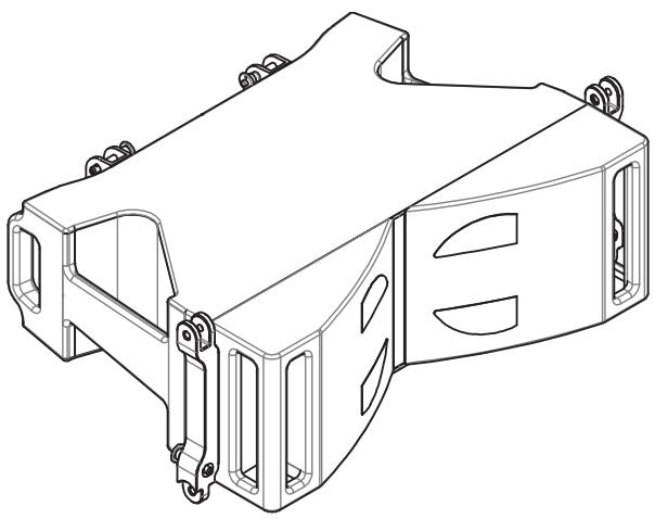
Superfly systems are designed to have a medium-long throw, so their 90° horizontal directivity enables to concentrate the acoustic energy adequately over long distances. On the other hand, for audience areas closer to the array, it may be necessary to use enclosures with wider horizontal directivity for correct sound reinforcement. It is therefore very effective to use elements with different characteristics from the mains ones', called downfills.
Along with Superfly it is possible to use Outline Mantas 28, which, having the same physical characteristics as Superfly and a horizontal directivity of 120° (see Superfly / Mantas 28 rigging manual"), can be used as an array in its own right, suitable for medium-sized events, as side fills, or as downfills to complement a Superfly array, without the use of adaptors.
Mantas 28 is a two-way system equipped with two partially horn-loaded 8" bandpass woofers and a driver with a 3" diaphragm coupled with a D.P.R.W.G. waveguide.
Mantas 28 foresees cabling with an NL4 connector (1+/1-LF; 2+/2-HF), and is connectable to the CA-BLA1-0X8 panel via four-pole cables with speakON connectors, or via SP4-LK8 cables (with a LK8 connector at one end and two speakON connectors at the other). With the MPULK-3X8 panel, SP2-LK8 cables must be used.
A specific X8 amplifier preset is also available for this speaker (Mantas 28 family).
Further details on www.outline.it

Mantas28: horizontal isobar diagram

Mantas28: vertical isobar diagram
9. ALIGNMENT AND TUNING
Once the flown Superfly array and the subwoofers are positioned, time-alignment must be carried out to ensure correct in-phase sound emission.
This alignment must be carried out using a measurement microphone and dual-FFT audio analysis software that enables to obtain the system's transfer function.
It is useful to know that the presets were created with the aim of having time alignment when the system's components (Superfly, Mantas 28 and DBS) are positioned “grille-to-grille” alongside each other. All this enables to have an estimate of the delay to assign to some of the system's components when they are located in different positions.


This fact will be of use in situations in which unreliable measurements are obtained, for example in locations with high reverberation.
To obtain an estimate of the delay, the distance must be measured from a specific point (e.g. FOH) in relation to the two macro-blocks (flown arrays and subwoofers in the diagram below).
After obtaining these distances (via laser distance meter for example), it is possible to calculate the delay to apply to the nearest macro-block (in this case the subwoofers) with a simple formula, i.e. dividing the difference obtained between the two by the speed of sound, or remembering that each metre corresponds to approximately 3 ms (to be precise 2.9 ms at 23 °C).

10. RAPID CHECKS: FASTQC-LS
It is always advisable to carry out a check of the system's electroacoustic components, before every use, in order to ascertain perfect operation. These tests are usually overlooked, particularly during set-up, due to the lack of sufficient time and the initial impossibility of using the amplification system.
This is why Outline has created FASTQC-LS, a tool that is battery-operated, so able to be used even without an electricity supply, in a simple rapid manner that is ideal for testing single components.
FASTQC-LS was designed for simultaneously measuring the resistance of each Outline element with several sections. It has an NL4 connector, an LK8 connector and the limit parameters for each enclosure it can measure are stored on board.
For standard use, connect it to the element to be measured with a short cable (e.g. the link cable used to connect enclosures in parallel), select the preset corresponding (↑↓) to the enclosure to be tested and press the “measure” button. The result is shown on the display and via the LEDs on the panel. If the measurement of each section is within the limit values, the result is positive. In the event of problems (the resistance is too high or too low, or there is a shortcircuit) it is necessary to consider the possibility of one or more of the sections of the element being damaged or a fault in the cable being used.
For other useful details on its use, consult the appropriate manual on www.outline.it

FASTQC-LS can also be used in measurement mode to test the cabling of a system that is already mounted, or to measure a system not manufactured by Outline. In this case the display shows the measurement of electrical resistance found for each single section.
11. CHECKS
All the components of the system (enclosures, amplifiers, cables, flying hardware, etc.) require a series of periodic checks with a timetable established at the discretion of those responsible for the work. Operating checks must also be repeated every time the system is used and must be established in order to confirm the full operating efficiency of each element.
The most in-depth checks must be carried out a regular intervals (e.g. every 6 or 12 months), following lengthy use (such as a system returning after a series of shows, tours or festivals), or following particular events (incorrect use, incorrect set-up, falls, etc.).
11.1. OPERATING INSPECTIONS/TESTS
For the electroacoustic components, a check is foreseen after each use:
- of each section of the system before set-up (strongly advised);
- of the external mechanical accessories (frame, motors, shackles, etc...);
- of the mechanics (conditions of connector brackets, bars and pins);
- of the electricity supply (generators or mains power, switchboards, cabling, etc.);
- of the system cabled to the amplifiers (operation of each individual channel of amplification via listening with test noise, testing of the correctness of the selected preset and the connections, testing of the connections with the sources, etc...) carried out by both listening and, whenever possible, with measurements;
• other miscellaneous aspects.
The aim of these tests is to ensure the optimum safe operation of the entire system from all points of view. If any defects are found, they must be corrected. If the defects are sufficient to compromise the device's use and safety, it must be immediately removed from service.
11.2. PERIODIC CHECKS
More in-depth checks will carried out to identify the causes of possible problems that could occur through time, and all the parameters that are difficult to measure or not completely measurable in day-to-day checks. It is therefore necessary to give priority to the following checks on:
- cables, connectors' compliance, relative wiring, no cuts, tears, cabling safety, etc...;
- amplifiers (for which the relative documentation must be referred to);
- switchboards, electrical distro panels, cabling panels and auxiliary components;
- enclosures' impedances (e.g. using the X8 amplifiers' Live Impedance function);
- frequency response of the electroacoustic elements (using a measurement microphone and analysis software that enables to measure the enclosures' frequency response, which must be compared with the reference curves);
-
other electroacoustic components (check that there is no vibration, that the panels are in good condition, etc...);
-
each element's hardware (perfect conditions and presence of all the components, no deformation, cracks or ovalization, search for signs of damage);
- external hardware/mechanism (rigging frame, rigging accessories, motors, etc.);
- accessory elements (trolleys, flight cases, trunks, etc.).
The objective of these checks is to have a system ready for use in a perfect safe manner at any time. The result of these inspections/tests must be reported in printed/written or electronic format, in a table such as that in the appendix.
If defects are found, the appropriate repair work must be carried out. This must be done by specialized staff, with care and attention, ensuring that the device's operation and safety are not compromised. In the event of any doubts, it is indispensable to contact the Outline representative or distributor or Outline itself.

Esempio generico di transfer function tra un segnale in uscita da un sistema sonoro e il corrispettivo segnale in ingresso da un microfono di misura.
- SPARES

2 x 10" neodymium woofers, spare part code: O S10246-16WP.

2 x 8" neodymium woofers, spare part code: O S851MB8WB.

1 x 3" compression driver, spare diaphragm code: O KCDM912CFF.
This driver uses a small quantity of ferrofluid (0.40 ml). Outline puts a ferrofluid kit at users' disposal (12 ml, code: H FEFLUID1120). The ferrofluid does not have to be replaced if it is already sufficient.
13. TECHNICAL CHARACTERISTICS
PHYSICAL
| Component Low | 2 x 10" NdFeB double reflex band-pass loaded woofer |
| Component Midrange | 2 x 8" NdFeB partially horn loaded mid woofer |
| Component High | 1 x 3" diaphragm NdFeB compression driver, DPRWG loaded |
| Connectors | 2 x LKI8 in parallel (8-pin, military grade) |
| Cabinet Material | Baltic birch plywood |
| Cabinet Finish | Black polyurea coating |
| Grill | Epoxy powder coated |
| Rigging | Integrated high-load aluminium hardware |
| Height | 239 mm - 9 3/8" |
| Height (rigging included) | 278 mm - 11" |
| Width | 909 mm - 35 3/4" |
| Depth | 636 mm - 25" |
| Weight | 38 kg - 83.8 lb |
PERFORMANCE SPECIFICATIONS
| Frequency Response -10 dB | 50 Hz – 20 kHz |
| Horizontal Dispersion | 90° |
| Vertical Dispersion | Array design dependent |
| Splay Angles available (Degrees) | from 0° to 7.5° in 0.5° step with additional 0.25° position |
| Operating configuration | Quad-amplified |
| Impedance Low (Nom / Min) | 2 x 16 Ω / 2 x 14.4 Ω |
| Impedance Midrange (Nom / Min) | 16 Ω / 12.6 Ω |
| Impedance High (Nom / Min) | 16 Ω / 15.9 Ω |
| Watt AES Low (Continuous / Peak) | 2 x 450 W / 2 x 1800 W |
| Watt AES Midrange (Continuous / Peak) | 400 W / 1600 W |
| Watt AES High (Continuous / Peak) | 120 W / 480 W |
| Maximum SPL Output, one box * | 143 dB SPL |
| Maximum SPL Output, four boxes * | 155 dB SPL |
* calculated using +10 dB Crest Factor signal @ 1 m, free field
FRONT VIEW

TOP VIEW

SIDE VIEW


APPENDIX A: PERIODIC INSPECTION TABLE
The following is an example of a table to be filled in for each periodic inspection/test carried out on every element.
The table can be adapted to suit measurement possibilities and must be relative to each enclosure's serial number. It can be written on paper or in electronic format.
| NUMERO DI SERIE: | ||||||||
| Date | ||||||||
| Electronic connections | ||||||||
| Cabinet states | ||||||||
| Grille | ||||||||
| Panels | ||||||||
| Transducer impedance | ||||||||
| Frequency response | ||||||||
| Rigging elements | ||||||||
| Rigging holes | ||||||||
| Pin | ||||||||
| Note: | ||||||||
Outline
Outline carries out on-going research for product improvement. New materials, manufacturing methods and design upgrades are introduced to existing products without prior notice as a routine result of this philosophy. For this reason, any current Outline product may differ is some aspect from its description, but will always equal or exceed the original design specifications unless otherwise stated.


- SUPERFLY
- CONTENTS
- SAFETY INSTRUCTIONS
- DESCRIPTION OF THE SYSTEM
- ADVANTAGES OF LINE ARRAY CONFIGURATION
- CABLING
- AMPLIFICATION
- SUPERFLY PRESET
- OPEN ARRAY 2 AND AIMING
- ADDITIONAL ELEMENTS
- ALIGNMENT AND TUNING
- RAPID CHECKS : FASTQC-LS
- CHECKS
- SPARES
- TECHNICAL CHARACTERISTICS
- APPENDIX A: PERIODIC INSPECTION TABLE
- INSTRUCTIONS FOR DISPOSAL
- COMPLIANCE AND GUARANTEE
- CONNECTOR SPECIFICATIONS
- OUT-RACK A
- OUT-RACK B
- AVAILABLE PRESETS
- DBS 18-2 SUBWOOFER
- MANTAS 28 DOWNFILL
- RAPID CHECKS: FASTQC-LS
- OPERATING INSPECTIONS/TESTS
- PERIODIC CHECKS
- OUTLINE
Brand : Outline
Model : SUPERFLY
Category : Speaker