
NV7 - Computer Case Phanteks - Free user manual and instructions
Find the device manual for free NV7 Phanteks in PDF.



User questions about NV7 Phanteks
0 question about this device. Answer the ones you know or ask your own.
Ask a new question about this device
Download the instructions for your Computer Case in PDF format for free! Find your manual NV7 - Phanteks and take your electronic device back in hand. On this page are published all the documents necessary for the use of your device. NV7 by Phanteks.
USER MANUAL NV7 Phanteks
NV7
USER MANUAL

THANK YOU FOR CHOOSING
PHANTEKS
1. INTRODUCTION
Introduction 5
D-RGB Lighting Effects 6
Exploded View 7
Accessories 8
Specifications 9
2. BUILD YOUR SETUP
Remove External Panels 10
Remove Covers 12
Motherboard Installation 13
Power Supply Installation 14
Fan & Radiator Positions 15
Fan & Radiator Installation 16
Airflow Configurations 20
Power Button & LED 21
Front I/O 22
Move Front I/O To Secondary Position 23
D-RGB Cables 24
Installing Storage 25
Internal Cable Management 27
Installing LED Covers 28
Installing GPU Support Bracket 30
External Cable Management 31
3. SUPPORT
Contact Us 32
Warranty 33
INTRODUCING THE PHANTEKS NV7
The Phanteks NV7 is a showcase full-tower chassis with a clean look from every side. It is the first installment of the new NV series, which is focused on showcasing your hardware in a premium build-quality chassis. Performance is uncompromised with Ultra-Fine Mesh panels while providing a clean and stylish look with the nearly seamless tempered glass front and left side panels.
THE PHANTEKS TEAM

The Digital-RGB lighting can be easily controlled with the 4 buttons on top of the chassis:

MODES

TURN OFF LEDs

Press and hold the MODE button for two seconds to turn off LEDs, press again to turn it ON
PARTS
1 Chassis
2 Front glass panel
3 Right side mesh panel
4 Left glass panel
5 Top panel
6 Bottom fan bracket
7 Side fan bracket
8 Rear door
9 Bottom dust filter
10 Front I/O
11 GPU Support Bracket
12 Motherboard Cover
13 D-RGB Cover
14 Top I/O
15 Rear Mesh Cover
16 Airflow Cover

GPU SUPPORT BRACKET
Included in accessory box

AIRFLOW COVER
2x Included in accessory box

SCREWS


SSD + MOTHERBOARD SCREW
34X


MOTHERBOARD STAND-OFF
1X


ANTI-SAG BRACKET THUMB SCREW
4X


EXTRA RIGHT SIDE PANEL SCREW
1X


PSU SCREW
4X


HDD LOCKING SCREW
9X


STAND-OFF REMOVAL TOOL
1X
OTHER ACCESSORIES
1x D-RGB Motherboard adapter cable
1x Microfiber Cloth
6x Zipties
1x Manual
CASE SPECIFICATIONS
| Dimension (DxWxH) | 532 x 253 x 586 mm / 20.9 x 10.0 x 23.1 in |
| Form Factor | Full Tower |
| Materials | Steel, Tempered Glass front and side panels |
| Motherboard Support | ATX, micro-ATX, mini-ITX, E-ATX (up to 277 mm wide), SSI-CEB (up to 290 mm w/o cover ) |
| Front I/O | Power switch, 1x USB 3.2 Gen2 Type-C, 2x USB 3.0, D-RGB Mode, D-RGB Color, D-RGB Speed, D-RGB Channel, Microphone/Headphone |
PCI SLOTS & DRIVE BAYS
| PCI Slots | 8x | |
| Internal 2.5" | 6x | |
| Internal 3.5" | 2x | |
| FAN | 120mm | 140mm |
| Side | 4x | - |
| Top | 3x | - |
| Bottom | 3x | 3x |
| Rear | 2x | - |
| RADIATOR | 120mm | 140mm |
| Side | up to 360 | - |
| Top | up to 360 | - |
| Bottom | up to 360 | up to 280 |
| Rear | up to 240 | - |
INCLUDED ACCESSORIES
| GPU Support Bracket | 1x |
| Airflow Cover | 2x |
| Toolbox | 1x |
| CLEARANCE | |
| GPU Length | 450 mm / 17.7 in |
| CPU Cooler Height | 185 mm / 7.3 in |
| PSU Length | 255 mm / 10.0 in |
| Side 360 Radiator | Maximum size: 132 x 440 mm |
| Side 360 Radiator Thickness | 65 mm (to GPU) |
| Top 360 Radiator | Maximum size: 132 x 440 mm |
| Rear 240 Radiator | Maximum size: 132 x 320 mm |
01 OPEN REAR PANEL

Open the rear door by pulling it from the bottom right corner.
02 REMOVE GLASS SIDE PANEL


Loosen the 2 thumb screws in the rear, slide the glass side panel to the rear and tilt it sideways to remove it.
03 REMOVE GLASS FRONT PANEL
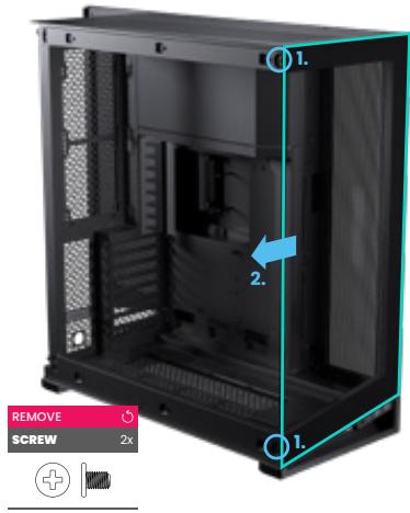
Unscrew the 2 screws from the left side and slide the panel to the left to remove it. Optionally, this panel can be left on during installation.
04 REMOVE TOP PANEL


Loosen the 2 thumb screws of the top panel in the rear. Slide the top panel to the rear to remove it.
05 REMOVE RIGHT SIDE PANEL

Remove the screw on the top and slide the right panel upwards to remove it.
06 REMOVE REAR DOOR

Optionally, remove the back door by sliding it upwards when it is in open position.
01 REMOVE D-RGB COVER

Slide the D-RGB cover to the front of the chassis to remove it.
02 REMOVE MOTHERBOARD COVER

Remove the screw located on the right side of the chassis. Push the motherboard cover down to remove it.

01 ALIGN MOTHERBOARD
Align the motherboard with the screwholes on the chassis' motherboard tray.
02 SECURE MOTHERBOARD
Secure the motherboard with 9x motherboard screws.


PRO TIP
Use the included stand-off tool to easily remove and re-install the motherboard stand-offs for other motherboard form-factors

ATTENTION
For Micro-ATX and SSI-CEB check the motherboard instructions for stand-off locations.
INSTALL
MB SCREWS

01 INSERT PSU
Insert the PSU from the right side of the chassis.

02 SECURE PSU
Secure the PSU from the rear with 4x PSU screws.

RADIATOR POSITIONS
Side: up to 360
Top: up to 360
Bottom: up to 360/280
Rear: up to 240

FAN POSITIONS
Side: 4x 120 mm
Top: 3x 120 mm
Bottom: 3x 120/140 mm
Rear: 2x 120 mm

AIR-COOLED CONFIGURATION
Side: Intake
Bottom: Intake
Top: Exhaust
Rear: Exhaust

WATER COOLED CONFIGURATION
Side: Exhaust
Bottom: Intake
Top: Exhaust
Rear: Exhaust

SIDE FAN/RADIATOR BRACKET


01 REMOVE SCREW
Remove the screw located on the top.
02 PULL & TAKE OUT BRACKET
Remove the bracket by pulling the handle at the top of the bracket and take it out.
03 INSTALL FANS/RADIATOR
Install up to 4x 120 fans/360 radiator on the bracket.
04 INSTALL SIDE BRACKET
Re-install the bracket and secure it with the screw located on the top.
Use the 3 cut-outs to route all fan cables.

PRO TIP
Use the provided airflow cover for optimal airflow. When used, the airflow will be closed off.
BOTTOM FAN/RADIATOR BRACKET


01 REMOVE BOTTOM BRACKET
Release the bracket by removing the rear thumb screw. Slide the bracket to the front to remove it.
02 INSTALL FANS/RADIATOR
Install up to 3x 120mm / 3x 140 mm fans and/or 280/360 radiator on to the bracket.
03 RE-INSTALL BOTTOM BRACKET
Re-install the bracket by sliding it towards the rear and secure it with the thumb screw.
It is possible to install the bracket the other way around for angled fans.
Fan cables can be routed through the cut-outs on the rear and side.
REAR FAN/RADIATOR POSITION
The rear has space for up to 240 radiator and 2x 120 fans. The fans can be installed in front of the rear panel while the radiator can be installed behind the rear panel.
01 REMOVE REAR MESH PANEL
Remove the screw on the rear and remove the mesh panel.
02 INSTALL FANS/RADIATOR
Install up to 2x 120 fans on the inside of the rear chassis. A 240 radiator can be installed on the outside of the rear chassis.
03 RE-INSTALL REAR MESH PANEL
If no radiator is installed, re-install the rear mesh panel.
Fan cables can be routed through the cut-outs on the rear.


TOP FAN/RADIATOR POSITION
01 INSTALL FANS/RADIATOR
Up to 3x 120 fans/360 radiator can be directly installed into the top of the chassis.
Fan cables can be routed through the cut-outs on the top.

01 CONNECT POWER BUTTON
Connect the power switch module to the motherboard.

power switch/power LED module

motherboard header diagram
I/O INTERFACE
• USB 3.1 GEN 2 TYPE-C (1x)
- USB 3.0 TYPE-A (2x)
• Headphone/microphone (1x)
CONNECT I/O CABLES TO MOTHERBOARD


STEPS TO MOVE I/O TO THE REAR
01 REMOVE BOTTOM FAN BRACKET
Remove the bottom fan bracket.
02 REMOVE SCREWS
Unscrew 2x screws located inside the chassis.
03 SLIDE I/O UNIT OUT
Slide the I/O unit forward and remove it.
04 PUSH OUT COVER
Push the cover, located on the rear bottom, up to remove it.
05 SLIDE I/O UNIT IN
Pull the cables through the cutout and slide the I/O unit into the rear position.
06 SECURE I/O UNIT
Secure the I/O unit in its new position with 2x screws.


D-RGB CONTROLLER
The built-in D-RGB controller has 2 channels (A & B). Both channels, each with 2 available D-RGB ports, can be controlled separately with the control buttons on the front I/O.
max 7A per channel, max 4A per port

LIGHTING EFFECTS & CONTROLS
D-RGB Lighting effects and control instructions are described on page 6.
01 CONNECT THE SATA CABLES
Connect the 2x SATA cables to the power supply.


02 EXPAND WITH OTHER D-RGB PRODUCTS
To Phanteks Digital-RGB products (JST connector)

03 SYNC LIGHTING TO MOTHERBOARD (OPTIONAL)
The D-RGB to motherboard cable is included in the accessory box.
sync lighting to the motherboard


5V D
Motherboard
D-RGB Header
TOP DOOR STORAGE
01 OPEN TOP DOOR
Loosen the thumb screw to open the top door.
02 INSTALL 2.5" DRIVES
Install up to 2x 2.5" drives with 2x SSD screws per SSD.


BOTTOM DOOR STORAGE
01 OPEN BOTTOM DOOR
Loosen the thumb screw to open the door.
02 INSTALL DRIVES
The bottom door can be used for one of the following storage options: 1x 3.5" + 4x 2.5" | 4x 2.5" | 2x 3.5"
OPTION A- 1X 3.5" + 4X 2.5"

OPTION B - 4X 2.5"

- Reposition the 2.5" drive bracket to the rear of the motherboard.
- Install 2x 2.5" drives on the door and 2x 2.5" drives on the bracket
OPTION C - 2X 3.5"

- Remove the 2.5" drive bracket completely.
- Install 2x 3.5" drives with cables routed to the top
PSU CABLE MANAGEMENT
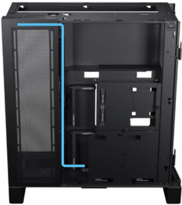
The PSU cables can be routed like the image below for clean cable management. Open the top cover door to loop the CPU & MB cables to get rid of excessive cable length.

Loop excessive cable length on the inside of the top cover door.

01 INSTALL MOTHERBOARD COVER
The motherboard cover can be installed in two ways:

Option 1: Default
The first option covers a bit more of the cables attached to the motherboard, and is a great fit for standard sized ATX motherboards.

Option 2: Reversed
For the second option, the cover is installed in reversed position. This covers less of the motherboard and allows more clearance for E-ATX motherboards (up to 277 mm).
Option 3: Remove Cover
For even larger motherboards and maximum clearance, it is recommended to remove this cover completely.

After choosing the preferred position, align the motherboard cover (1) and slide upwards (2). Secure it with the thumb screw through the right side of the chassis (3).
02 INSTALL D-RGB COVER

Slide the D-RGB cover to the rear of the chassis to install it.
01 INSTALL BRACKET
Install the GPU support bracket on the motherboard cover with 1x thumb screw.
02 ADJUST HEIGHT
Adjust to the correct height for your GPU and use the thumb screw to secure it.
03 ADJUST DEPTH
Adjust the depth of the bracket to hold the GPU tightly and lock with 1x thumb screw underneath the bracket.


PRO TIP
Use the tie point on the bracket to tie down GPU cable for a clean routing
CABLE LANES
External cables can be managed with the cable lanes behind the rear door. The left lane is larger and can be used for thick cables. The other three lanes are smaller and made for thin cables.

VELCRO TIE
Use the velcro tie on the bottom to tie all cables down to the chassis.

COMB OR GROMMET
There are two options for the cables to leave the case:
Option 1: Rear comb
The rear comb can be used to separate each cable to leave the case neatly.

Option 2: Bottom grommet
Alternatively, the grommet on the bottom of the chassis can be used to lead the cables out.

INTERNATIONAL
RMA & Technical Support
Internationaler RMA und technischer Support | RMA international et support technique | RMA internacional y soporte técnico | 国际 RMA 和技术支持
support@phanteks.com
AMERICAS
RMA & Technical Support
Hours
Monday - Friday
09:00 - 05:00 PST
Phone Number
+1 (909) 598 2115
support@phanteksusa.com
WARRANTY
Garantie | Garantie | Garantía | 保修单
- I/O Ports
2 Years
- LED Lighting
2 Years
- Buttons
2 Years
- Chassis
5 Years
- External Panels
5 Years

For the latest information on the product, manual, service and warranty please visit www.phanteks.com

Die neuesten Informationen zu Produkt, Handbuch, Service und Garantie finden Sie unter www.phanteks.com

Pour les dernières informations sur le produit, le manuel, le service et la garantie, veuillez visiter www.phanteks.com

Para obtener la información más reciente sobre el producto, manual, servicio y garantía, visite www.phanteks.com

有关产品、手册、服务和保修的最新信息,请访问 www.phanteks.com
In order to achieve maximum safety, we suggest that you adopt the following guidelines:
- Place the product on a clean and stable surface that allows adequate air ventilation.
- Don't use or place the product and any of its components near water, moisture, or other wet surfaces; or place the product near any heat, open flame, or other hot surfaces such as radiators, stoves, fireplaces, and candles.
- Use caution when operating the desktop PC to avoid electrical shock or damage, such as unplugging the power supply during thunderstorms, ensuring that your hands are dry before using (and handling) the desktop PC, keeping it away from any source of liquid and/or heat source, and using all other reasonable precautions needed under the circumstances.
- When connecting external devices to your desktop PC, carefully plan how the wires will be placed. Protect any connected cables from being trod on or pinched, particularly at plugs, convenience receptacles, or the point where they exit from.
- Take extra caution when handling/removing/reattaching glass components. Once removed, place the glass component on a stable surface first before proceeding.
- When unplugging any connected devices and/or cables, always pull the cable or device's plug or connector. Don't forcefully tug on its cord.
- Don't place any heavy items on top of the product.
- Make sure that the desktop PC is off, unplugged from the outlet, and that all connected devices are powered off and unplugged (if any) before installing or uninstalling any internal component to and/or from the desktop PC or product.

FR
Cet appareil se recycle
REPRISE À LA LIVRAISON

À DÉPOSER EN MAGASIN

À DÉPOSER EN DÉCHÈTERIE

Points de collecte sur www.quefairedemesdechets.fr Privilégiez la réparation ou le don de votre appareil !

The WEEE symbol indicates that this product must not be disposed of with normal household waste. Through the correct disposal of this product, you will help protect the environment. For more information on the disposal of this product, please contact your local municipality, your waste disposal service or the shop where you purchased the product.
Phanteks Taiwan Inc.
11F., No. 150, Jian 1st Rd., Zhonghe Dist.
New Taipei City 235
Importer EU
Axpertec Int. B.V. (EU)
Sydneystraat 33
3047 BP Rotterdam
The Netherlands
Importer US
Axpertec Inc. (US)
20465 E Walnut Dr. N
City of Industry, CA 91789
USA
FOLLOW US
SOCIAL MEDIA

Phanteks

Phanteks

YouTube
Phanteks

@phanteks




- NV
- USER MANUAL
- THANK YOU FOR CHOOSING
- PHANTEKS
- INTRODUCTION
- BUILD YOUR SETUP
- SUPPORT
- INTRODUCING THE PHANTEKS NV
- THE PHANTEKS TEAM
- PARTS
- GPU SUPPORT BRACKET
- AIRFLOW COVER
- SCREWS
- OTHER ACCESSORIES
- OPEN REAR PANEL
- REMOVE GLASS SIDE PANEL
- REMOVE GLASS FRONT PANEL
- REMOVE TOP PANEL
- REMOVE RIGHT SIDE PANEL
- REMOVE REAR DOOR
- REMOVE D-RGB COVER
- REMOVE MOTHERBOARD COVER
- ALIGN MOTHERBOARD
- SECURE MOTHERBOARD
- PRO TIP
- ATTENTION
- INSERT PSU
- SECURE PSU
- RADIATOR POSITIONS
- FAN POSITIONS
- AIR-COOLED CONFIGURATION
- WATER COOLED CONFIGURATION
- REMOVE SCREW
- PULL & TAKE OUT BRACKET
- INSTALL FANS/RADIATOR
- INSTALL SIDE BRACKET
- REMOVE BOTTOM BRACKET
- RE-INSTALL BOTTOM BRACKET
- REAR FAN/RADIATOR POSITION
- REMOVE REAR MESH PANEL
- RE-INSTALL REAR MESH PANEL
- TOP FAN/RADIATOR POSITION
- CONNECT POWER BUTTON
- I/O INTERFACE
- CONNECT I/O CABLES TO MOTHERBOARD
- STEPS TO MOVE I/O TO THE REAR
- REMOVE BOTTOM FAN BRACKET
- REMOVE SCREWS
- SLIDE I/O UNIT OUT
- PUSH OUT COVER
- SLIDE I/O UNIT IN
- SECURE I/O UNIT
- D-RGB CONTROLLER
- LIGHTING EFFECTS & CONTROLS
- CONNECT THE SATA CABLES
- EXPAND WITH OTHER D-RGB PRODUCTS
- SYNC LIGHTING TO MOTHERBOARD (OPTIONAL)
- TOP DOOR STORAGE
- OPEN TOP DOOR
- INSTALL 2.5" DRIVES
- BOTTOM DOOR STORAGE
- OPEN BOTTOM DOOR
- INSTALL DRIVES
- PSU CABLE MANAGEMENT
- INSTALL MOTHERBOARD COVER
- OPTION 1: DEFAULT
- OPTION 2: REVERSED
- OPTION 3: REMOVE COVER
- INSTALL BRACKET
- ADJUST HEIGHT
- ADJUST DEPTH
- CABLE LANES
- VELCRO TIE
- COMB OR GROMMET
- OPTION 1: REAR COMB
- OPTION 2: BOTTOM GROMMET
- INTERNATIONAL
- AMERICAS
- WARRANTY
- IN ORDER TO ACHIEVE MAXIMUM SAFETY, WE SUGGEST THAT YOU ADOPT THE FOLLOWING GUIDELINES
- FR
- CET APPAREIL SE RECYCLE
- PHANTEKS TAIWAN INC
- IMPORTER EU
- IMPORTER US
- SOCIAL MEDIA
Brand : Phanteks
Model : NV7
Category : Computer Case