
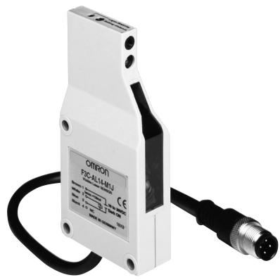
F3C-AL - Laser photoelectric sensor OMRON - Free user manual and instructions
Find the device manual for free F3C-AL OMRON in PDF.
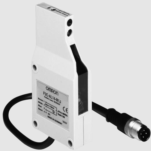
| Product type | Laser photoelectric sensor |
| Brand | OMRON |
| Model | F3C-AL (F3C-AL14-M1J / F3C-AL44-M1J) |
| Detection range (adjustment) | 170 to 700 mm (white paper 90% reflectance) |
| Detection distance | 120 to 700 mm (white paper 100x100 mm) |
| Light source | Pulsed red semiconductor laser, class II, <1 mW, 670 nm |
| Laser class | Class 2 (IEC 60825-1) |
| Power supply voltage | 10 to 30 VDC (ripple 10% max.) |
| Current consumption | 30 mA max. |
| Control output | NPN or PNP open collector, 150 mA max., selectable Light-ON/Dark-ON |
| Response time | 10 ms max. (ON and OFF) |
| Protections | Polarity reversal, output short-circuit, mutual interference prevention |
| Operating temperature | 0°C to 50°C (no frost or condensation) |
| Ambient humidity | 35% to 85% RH (no condensation) |
| Weight | Approx. 80 g (packaged) |
| Spot diameter | 1.5 x 4 mm (at 700 mm) |
| Black/white error | 2% (at 300 mm), 8% max. (at 500 mm) |
| Hysteresis | 0.5% max. (white paper) |
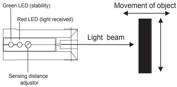
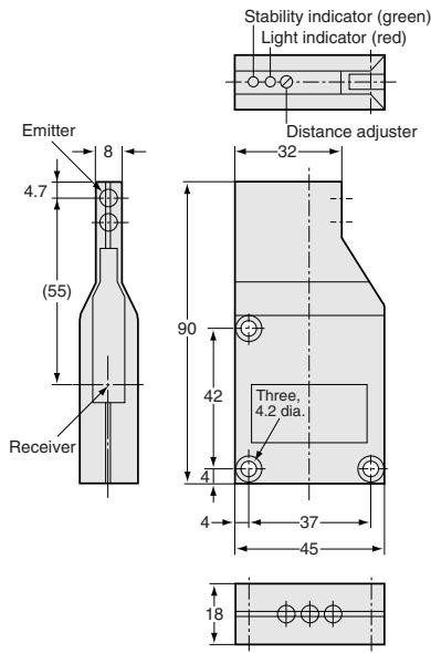
| Indicators | LIGHT (red), STABILITY (green) |
| Sensitivity adjustment | 6-turn potentiometer |
| Connection | M12 connector, 4-pin (200 mm cable) |
| Housing material | ABS |
| Protection degree | IP40 (IEC) |
| Included accessories | Adjustment screwdriver, laser warning label, instruction manual |
| Mounting | M4 screws, tightening torque max. 1.2 Nm |
Frequently Asked Questions - F3C-AL OMRON
User questions about F3C-AL OMRON
0 question about this device. Answer the ones you know or ask your own.
Ask a new question about this device
Download the instructions for your Laser photoelectric sensor in PDF format for free! Find your manual F3C-AL - OMRON and take your electronic device back in hand. On this page are published all the documents necessary for the use of your device. F3C-AL by OMRON.
USER MANUAL F3C-AL OMRON
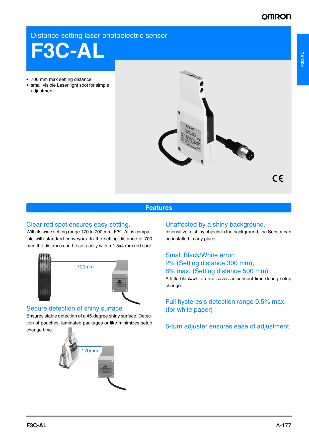
Distance setting laser photoelectric sensor
F3C-AL
- 700 mm max setting distance
- small visible Laser light spot for simple adjustment
C E
Features
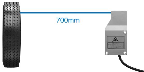
Clear red spot ensures easy setting.
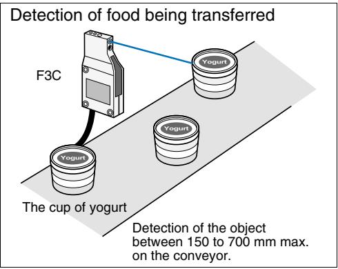
With its wide setting range 170 to 700 mm, F3C-AL is compatible with standard conveyors. In the setting distance of 700 mm, the distance can be set easily with a 1.5 × 4 mm red spot.
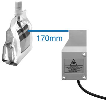
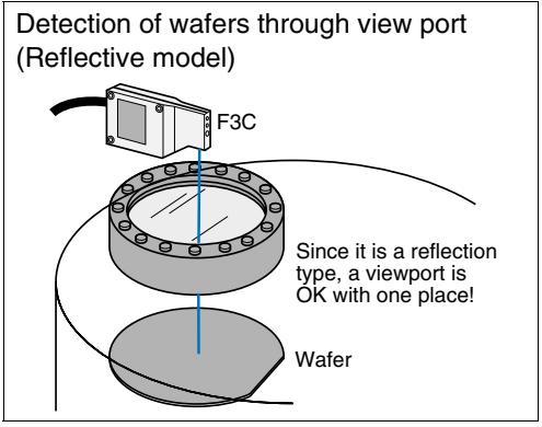
Secure detection of shiny surface
Ensures stable detection of a 45-degree shiny surface. Detection of pouches, laminated packages or like minimizes setup change time.
Unaffected by a shiny background.
Insensitive to shiny objects in the background, the Sensor can be installed in any place.
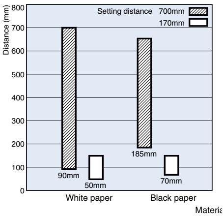
Small Black/White error:
2% (Setting distance 300 mm),
8% max. (Setting distance 500 mm)
A little black/white error saves adjustment time during setup change.
Full hysteresis detection range 0.5% max. (for white paper)
6-turn adjuster ensures ease of adjustment.
Application
Ordering Information
Red light
Sensors
| Shape | Connection method | Sensing/Setting range | Operating mode | Model | |
| NPN output | PNP output | ||||
| Pre-wired with M12-connector | 120 700 mm Setting range Sensing distance 120 to 700 mm | Light-ON/Dark-ON cable connection selectable | F3C-AL14-M1J | F3C-AL44-M1J | |
Accessories (Order Separately)
Mounting Brackets
| Shape | Model | Quantity |
| E39-L40 | 1 |
Sensor I/O Connectors
| Cable specifications | Shape | Cable type | Model | |
| Standard cable | Straight type | 2 m | 4 conductors | XS2F-D421-D80-A |
| 5 m | XS2F-D421-G80-A | |||
| L type | 2 m | XS2F-D422-D80-A | ||
| 5 m | XS2F-D422-G80-A | |||
| Robot cable (for vibration resistance) | Straight type | 2 m | XS2F-D421-D80-R | |
| 5 m | XS2F-D421-G80-R | |||
| L type | 2 m | XS2F-D422-D80-R | ||
| 5 m | XS2F-D422-G80-R | |||
Rating/Performance
| Item | Model | F3C-AL14-M1J | F3C-AL44-M1J |
| Sensing | 120 to 700 mm (White paper 100 x 100 mm) (Setting distance 700 mm) | ||
| Setting distance range | 170 to 700 mm (White paper, 90% remission, 100 x 100 mm)170 to 560 mm (White paper, 6% remission, 100 x 100 mm) | ||
| Black-/white-error | 20% max. (of setting distance, 90%/6% remission) | ||
| Spot Diameter | 1.5 x 4 mm (Setting distance 700 mm) | ||
| Light source | Pulsed red light semiconductor laserClass II: < 1mWeff. / 670 nm / 5% duty cycle(Impulse time 60 μs, Period time: 1.2 ms) | ||
| Power supply voltage | 10 to 30 VDC [ripple (p-p) 10% included] | ||
| Current consumption | 30 mA max. | ||
| Control output | Load supply voltage 30 VDC max., load current 150 mA max. (residual voltage: 2 V max.)NPN open collector output type, Light-ON/Dark-ON cable connection selectable | Load supply voltage 30 VDC max., load current 150 mA max. (residual voltage: 2 V max.)PNP open collector output type, Light-ON/Dark-ON cable connection selectable | |
| Protective circuits | Reverse polarity protection, output short-circuit protection, mutual interference prevention | ||
| Response time | Operation and reset: 10 ms max. | ||
| Sensitivity adjustment | 6-turn adjuster | ||
| Ambient illuminance | Incandescent lamp/Sunlight: 5,000 lux max. | ||
| Ambient temperature | Operating: 0°C to 50°C, Storage: -25°C to 60°C (with no icing or condensation) | ||
| Ambient humidity | Operating/Storage: 35% to 85%RH (with no condensation) | ||
| Insulation resistance | 20 M min. at 500 VDC | ||
| Vibration resistance | 10 to 55 Hz double amplitude 1.5 mm or 300 m/s² for 2 h in each of X, Y, Z directions | ||
| Shock resistance | Destruction: 500 m/s² for 3 times each in X, Y, and Z directions | ||
| Protective structure | IEC Standard IP40 | ||
| Connection method | M12 connector joint type (standard cable length 200 mm) / 4 x 0.34 mm² (PVC) | ||
| Weight (packed state) | Approx. 80 g | ||
| Material | Case | ABS | |
| Lens | Acrylics (PMMA) | ||
| Accessories | Adjusting screwdriver, Laser warning label, instruction manual | ||
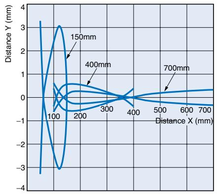
Parallel operating range
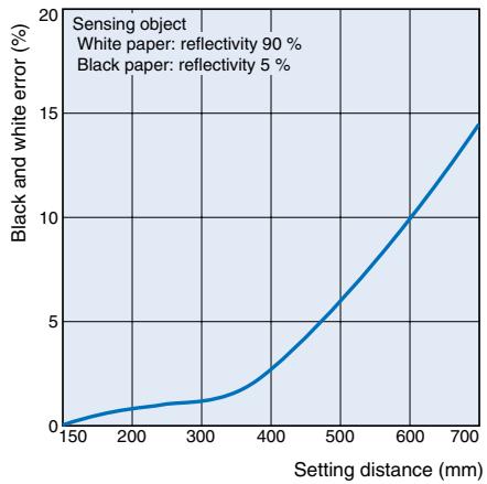
Black/White error
Short distance characteristic chart
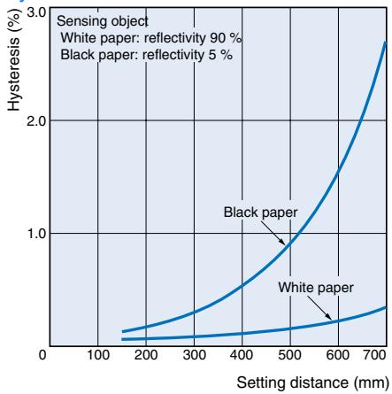
Hysteresis
NPN output
| Model | Operating status of output transistor | Timing chart | Mode selection | Output circuit |
| F3C-AL14-M1J | Light ON | Incident Interrupted Light indicator (red) ON OFF Output transistor Load (Relay) Operate Reset (Between 1 and 4) | Connect ② to ① or dis- connect ②. | 10 to 30 VDC Load (Relay) 150 mA max. 0V Operation selectable Connector Pin Arrangement ①②④③ |
| Dark ON | Incident Interrupted Light indicator (red) ON OFF Output transistor Load (Relay) Operate Reset (Between 1 and 4) | Connect ② to ③. | 10 to 30 VDC Load (Relay) 150 mA max. 0V Operation selectable Connector Pin Arrangement 10 to 30 VDC ①②④③ |
PNP output
| Model | Operating status of output transistor | Timing chart | Mode selection | Output circuit |
| F3C-AL44-M1J | Light ON | Incident Interrupted Light indicator (red) ON OFF Output transistor Load (Relay) Operate Reset (Between 3 and 4) | Connect (2) to (1) or dis- connect (2). | 10 to 30 VDC 150 mA max. Load (Relay) 0V Operation selectable Connector Pin Arrangement ①②④③ |
| Dark ON | Incident Interrupted Light indicator (red) ON OFF Output transistor Load (Relay) Operate Reset (Between 3 and 4) | Connect (2) to (3). | 10 to 30 VDC 150 mA max. Load (Relay) 0V Operation selectable Connector Pin Arrangement ①②④③ |
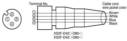
Connectors (Sensor I/O connectors)
| Class | Wire, outer | Connector | Application |
| For DC | Brown | ① | Power supply (+V) |
| White | ② | Operation switching | |
| Blue | ③ | Power supply (0 V) | |
| Black | ④ | Output |
Sensitivity Adjustment
| Item | Position A | Position B and C | Setting |
| Adjustment procedure | Place the detected object at the desired location and turn the LIGHT indicator (red) lights. This is position A | Background object Remove the detected object and turn the adjustment knob clockwise until the LIGHT indicator(red) lights. This is the position B. Then turn the adjustment knob counterclockwise until the LIGHT indicator (red) goes out. This is position C. No Background object The maximum adjustment setting is used as position C. | Set the adjustment to halfway between A and C. Confirm that the STAB indicator (green) remains lit both with the detected object present and not present. If the STAB indicator does not remain lit, review the detection method to enable stable operation. |
| Detecting condition | Photoelectric sensor Detected object A A B | Photoelectric sensor Detected object C B | |
| Status of distance setting knob | A B | C B | A C |
| Indicators | OFF ON LIGHT (green) ON LIGHT (red) | OFF STABILITY (green) OFF LIGHT (red) | ON STABILITY (green) OFF LIGHT (red) |
Special hints
Recommended adjustment
To assure stable working conditions the green stability LED should be always turned on.
The green LED displays two stability conditions:
- Output stable ON (red LED on)
- Output stable OFF (red LED off)
Best performance can be achieved if the sensing object is located
closer than -10 % of the setting distance or the shiny background is
fixed +10 % behind the switching position.
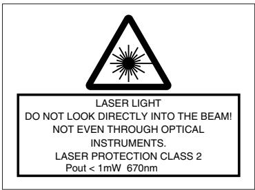
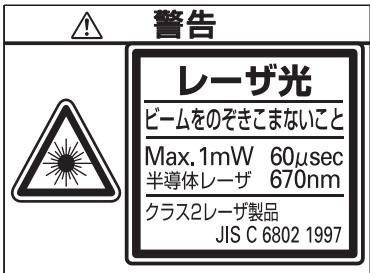
Safety Precaution
Laser beam!

Laser protection class 2
Do not look into the laser beam.
Pay attention to the accident prevention regulations and the laser protection class.
Visible laser emission!
Avoid any indirect or direct radiation of
reflected or emitted laser light!
Laser safety
The laser safeguards have been stipulated for laser equipment in and outside Japan. The following gives brief description for use in Japan.
The JIS C6802 Standard stipulates safety preventives that must be taken by the user according to the laser product class. (The outline is given in the following table.)
User's Requirements
| Class Item | Class 1 | Class 2 | Class 3A | Class 3B | Class 4 | |
| 3B* | 3B | |||||
| Using remote interlock | Not required | Connect the re-mote interlock of the laser beam to the emergency main interlock, the interlock of the room, or the inter-lock of the door. | ||||
| Key control | Not required | Do not keep the key in the lock when the laser beam is not used. | ||||
| Beam breaker or attenuator | Not required | Used to protect people from accidental radiation by the laser beam. | ||||
| Warning sign | Not required | Post a proper warning sign on the door to the room where laser beam equipment is installed. | ||||
| Beam path | Not required | The laser beam must be terminated and, as a rule, must be enclosed. If the laser beam is exposed, the vertical height of the beam must not be the same as that of the eyes. | ||||
| Mirror reflection | Not required | Appropriate optical elements must be securely attached and you must be able to control the optical elements during laser radiation. | ||||
| Eye protect | Not required | Use eye protectors except in special, specified locations. | ||||
| Protection clothes | Not required | Wear protection clothes if exposure of the skin to the laser beam may exceed the MPE of the skin. | ||||
| Training | Not required | The laser system must be operated by only properly trained people. | ||||
- 5 mW or less in the visible range
Classification of F3C
Class 2
Handle laser equipment in accordance with the following precautions.
- Do not look into the beam.
- Do not disassemble the product. Doing so will release the laser beam to wander around.
Please obtain or prepare the "Laser product safety standards" on your own responsibility.
Labels related to laser
The following warning label is applied to the side face of the photoelectric sensor.
For use in Japan, change the above label for the one that meets the JIS Standards.
Handling Instructions
F3C radiates a visible-light laser. Do not look into it directly. Use F3C so that the light path of the laser beam is terminated. If there is a mirror-smooth reflector in the light path, confine the beam away from the reflected light path. If F3C must be used with the light path open, avoid placing the light path on the eye level.
Correct Use
Design
Power Reset Time
The Photoelectric Sensor is ready to sense an object in 300 ms after power-on. Therefore, use it 300 ms after power-on. If the load and Sensor are connected to different power supplies, always switch on power for the Sensor first.
Wiring Considerations
Load short-circuit protection
- The F3C-AL has load short-circuit protection. If a load short-circuit or like has occurred, the output turns OFF. Therefore, recheck the wiring and switch power on again. This resets the short-circuit protection circuit. Load short-circuit protection is activated when a current of 1.8 times or more of the rated load current flows. When using an L load, use the one the inrush current of which is less than 1.8 times of the rated load current.
- Do not use the input power exceeding the rated voltage. Doing so can cause damage.
- Do not shorten the load with the open collector output. Otherwise, damage might be caused.
-
Run the wiring of F3C separately from the high voltage and power cables.
-
Avoid wiring them together or running them within the same duct. Doing so may get them induced, causing a malfunction or damage.
- For extension of the cable, use a 0.3mm^2 or more cable and run it within 50m .
Mounting
- Install the photoelectric sensor so that the sun, fluorescent lamp, incandescent lamp or any other strong light will not enter the directional angle range of the sensor.
- If Sensors are installed face-to-face, ensure that no optical axes cross each other. Otherwise, mutual interference may result.
- Use M4 screws to mount the unit.
- When mounting the case tighten it to the torque of 1.2 Nm max.
Miscellaneous
Operating Environment
-
Avoid using the Sensor in a strong disturbance light (e.g. laser beam or arc welding beam) or strong electromagnetic field.
-
Depending on their material and/or shape, some objects may not be detected or may be detected with low accuracy. (Mirror-smooth material, transparent material, material of extremely low reflectivity, object smaller than spot diameter)
Correct operation
The moving direction of the sensor or object should be preferably along the optical axis of the light beam. Lateral approach is also possible. Movement from the top to the bottom or opposite can cause malfunction and should be avoided.
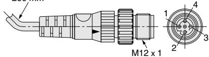
Dimensions (Unit: mm)
Sensors
F3C-AL14-M1J
F3C-AL44-M1J
| Termi-nal No. | Specifications |
| 1 | +V |
| 2 | L-ON/D-ON selection |
| 3 | 0V |
| 4 | Output |
Note. L-ON when 1-2 are connected D-ON when 2-3 are connected
inyl-insulated round cable of 4 dia. 4 cores conductorStandard length: 200mm
Accessories (Order Separately)
Mounting Brackets
H-5
ALL DIMENSIONS SHOWN ARE IN MILLIMETERS.
To convert millimeters into inches, multiply by 0.03937. To convert grams into ounces, multiply by 0.03527.
Cat. No. E510-E2-01-X
In the interest of product improvement, specifications are subject to change without notice.