
E5CSV-U - Thermometer OMRON - Free user manual and instructions
Find the device manual for free E5CSV-U OMRON in PDF.


| Product Type | Digital Temperature Controller |
| Model | E5CSV-U |
| Brand | Omron |
| Power Supply | 100-240 VAC, 50/60 Hz |
| Dimensions | 48 x 48 x 84 mm (panel cutout 45 x 45 mm) |
| Weight | Approx. 150 g |
| Display Type | LED, 4 digits |
| Input Type | Thermocouple (K, J, T, etc.) or RTD (Pt100) |
| Output Type | Relay (SPDT) or Voltage pulse for SSR |
| Control Method | ON/OFF or PID |
| Accuracy | ±0.5% of full scale |
| Key Functions | Set point adjustment, alarm settings, auto-tuning |
| Protection Rating | IP66 (front panel) |
| Operating Temperature | 0 to 50°C |
| Cleaning | Wipe with dry cloth; avoid solvents |
| Safety Standards | CE, UL listed |
| Spare Parts | Replacement thermocouples, mounting brackets |
| Repairability | Professional service recommended; no user-serviceable parts |
Frequently Asked Questions - E5CSV-U OMRON
User questions about E5CSV-U OMRON
0 question about this device. Answer the ones you know or ask your own.
Ask a new question about this device
Download the instructions for your Thermometer in PDF format for free! Find your manual E5CSV-U - OMRON and take your electronic device back in hand. On this page are published all the documents necessary for the use of your device. E5CSV-U by OMRON.
USER MANUAL E5CSV-U OMRON
Industrial Automation Company
Control Devices Division H.Q.
Analog Controller Division
Shickoj Bonkaya, Shimogyo-ku
Tel: (81)75-344-7080/Fec: (81)75-344-7189
Regional Headquarters
OMRON EUROPE B.V.
OMRON ELECTRONICS LLC
T.E.A. Collinace Limited, Schulmanburg, 12 B0175 U.S.A.
Tel: (1)647-843-7900VFSas; (1)647-843-8568
ONRON ASIA PACIFIC RTE LTD
93 Clemenceau Avenue.
11-01, UE Square.
259320 Singapore
Tel. (02) 0100-631 in Tel. (03) 0100-271
DMRON (CHINA) CO., LTD.
300 Yin Chong Road (M)
Shanghai 200120 China
Tel: (85)21-5037-2222 Fax: (85)21-5037-2200
In the interest of product improvement, specifications are
subject to change without notice.
Authorized Distributor:
Note: Specifications subject to change without notice Cat. No. H140-F1-01
1005

OMRON products are manufactured for use according to proper procedures by a qualified operator and only for the purposes described in this manual.
The E5CSV and E5CS-U are Compact Digital Temperature Controllers. The E5CSV features screw terminal connections, and the E5CS-U features socket pin connections. The main functions and characteristics of these Compact Digital Temperature Controllers are as follows:
- Any of the following types of input can be used: Thermocouple, platinum resistance thermometer, or thermistor input.
- High precision of ± 1% FS is possible even for plug-in models due to the built-in microcomputer (E5CSV: ± 0.5% FS).
• The optimum temperature range can be selected from multiple temperature ranges.
• Clear digital display with character height of 13.5 mm.
• Both auto-tuning and self-tuning are supported.
• The structure is waterproof (IP66). (Not applicable to the E5CS-U.) - Conforms to UL, CSA, and IEC safety standards and EMC Directive.
This manual describes the E5CSV and E5CS-U. Read this manual thoroughly and be sure you understand it before attempting to use the Compact Digital Temperature Controller and use the Compact Digital Temperature Controller correctly according to the information provided. Keep this manual in a safe place for easy reference.
Warranty and Limitations of Liability
WARRANTY
OMRON's exclusive warranty is that the products are free from defects in materials and workmanship for a period of one year (or other period if specified) from date of sale by OMRON.
OMRON MAKES NO WARRANTY OR REPRESENTATION, EXPRESS OR IMPLIED, REGARDING NON-INFRINGEMENT, MERCHANTABILITY, OR FITNESS FOR PARTICULAR PURPOSE OF THE PRODUCTS. ANY BUYER OR USER ACKNOWLEDGES THAT THE BUYER OR USER ALONE HAS DETERMINED THAT THE PRODUCTS WILL SUITABLY MEET THE REQUIREMENTS OF THEIR INTENDED USE. OMRON DISCLAIMS ALL OTHER WARRANTIES, EXPRESS OR IMPLIED.
LIMITATIONS OF LIABILITY
OMRON SHALL NOT BE RESPONSIBLE FOR SPECIAL, INDIRECT, OR CONSEQUENTIAL DAMAGES, LOSS OF PROFITS OR COMMERCIAL LOSS IN ANY WAY CONNECTED WITH THE PRODUCTS, WHETHER SUCH CLAIM IS BASED ON CONTRACT, WARRANTY, NEGLIGENCE, OR STRICT LIABILITY.
In no event shall the responsibility of OMRON for any act exceed the individual price of the product on which liability is asserted.
IN NO EVENT SHALL OMRON BE RESPONSIBLE FOR WARRANTY, REPAIR, OR OTHER CLAIMS REGARDING THE PRODUCTS UNLESS OMRON'S ANALYSIS CONFIRMS THAT THE PRODUCTS WERE PROPERLY HANDLED, STORED, INSTALLED, AND MAINTAINED AND NOT SUBJECT TO CONTAMINATION, ABUSE, MISUSE, OR INAPPROPRIATE MODIFICATION OR REPAIR.
Application Considerations
SUITABILITY FOR USE
OMRON shall not be responsible for conformity with any standards, codes, or regulations that apply to the combination of products in the customer's application or use of the products.
At the customer's request, OMRON will provide applicable third party certification documents identifying ratings and limitations of use that apply to the products. This information by itself is not sufficient for a complete determination of the suitability of the products in combination with the end product, machine, system, or other application or use.
The following are some examples of applications for which particular attention must be given. This is not intended to be an exhaustive list of all possible uses of the products, nor is it intended to imply that the uses listed may be suitable for the products.
- Outdoor use, uses involving potential chemical contamination or electrical interference, or conditions or uses not described in this manual.
- Nuclear energy control systems, combustion systems, railroad systems, aviation systems, medical equipment, amusement machines, vehicles, safety equipment, and installations subject to separate industry or government regulations.
- Systems, machines, and equipment that could present a risk to life or property.
Please know and observe all prohibitions of use applicable to the products. NEVER USE THE PRODUCTS FOR AN APPLICATION INVOLVING SERIOUS RISK TO LIFE OR PROPERTY WITHOUT ENSURING THAT THE SYSTEM AS A WHOLE HAS BEEN DESIGNED TO ADDRESS THE RISKS, AND THAT THE OMRON PRODUCTS ARE PROPERLY RATED AND INSTALLED FOR THE INTENDED USE WITHIN THE OVERALL EQUIPMENT OR SYSTEM.
PROGRAMMABLE PRODUCTS
OMRON shall not be responsible for the user's programming of a programmable product, or any consequence thereof.
| Disclaimers |
| CHANGE IN SPECIFICATIONSProduct specifications and accessories may be changed at any time based on improvements and other reasons.It is our practice to change model numbers when published ratings or features are changed, or when significant construction changes are made. However, some specifications of the products may be changed without any notice. When in doubt, special model numbers may be assigned to fix or establish key specifications for your application on your request. Please consult with your OMRON representative at any time to confirm actual specifications of purchased products. |
| DIMENSIONS AND WEIGHTSDimensions and weights are nominal and are not to be used for manufacturing purposes, even when tolerances are shown. |
| PERFORMANCE DATAPerformance data given in this manual is provided as a guide for the user in determining suitability and does not constitute a warranty. It may represent the result of OMRON's test conditions, and the users must correlate it to actual application requirements. Actual performance is subject to the OMRON Warranty and Limitations of Liability. |
| ERRORS AND OMISSIONSThe information in this document has been carefully checked and is believed to be accurate; however, no responsibility is assumed for clerical, typographical, or proofreading errors, or omissions. |
Notice
(1) All rights reserved. No part of this manual may be reprinted or copied without the prior written permission of OMRON.
(2) The specifications and other information contained in this manual are subject to change without notice in order to make improvements.
(3) Every precaution has been taken in the preparation of this manual. Nevertheless, OMRON assumes no responsibility for errors or omissions. If you discover any problems with this manual, please notify your nearest OMRON representative, providing them with the catalog number provided on the cover.
Safety Precautions
Definition of Precautionary Information
The following notation is used in this manual to provide precautions required to ensure safe usage of the product.
The safety precautions that are provided are extremely important to safety.
Always read and heed the information provided in all safety precautions.
The following notation is used.

CAUTION
Indicates a potentially hazardous situation which, if not avoided, may result in minor or moderate injury or in property damage.
Symbols
| Symbol | Meaning | |
| Caution |  | General CautionIndicates non-specific general cautions, warnings, and dangers. |
 | Electrical Shock CautionIndicates possibility of electric shock under specific conditions. | |
| Prohibition |  | General ProhibitionIndicates non-specific general prohibitions. |
 | Disassembly ProhibitionIndicates prohibitions when there is a possibility of injury, such as from electric shock, as the result of disassembly. | |
| Mandatory caution |  | General CautionIndicates non-specific general cautions, warnings, and dangers. |
- Safety Precautions
| CAUTION | |
| Do not touch the terminals while power is being supplied. Doing so may occasionally result in minor injury due to electric shock. |  |
| Do not allow pieces of metal, wire clippings, or fine metallic shavings or filings from installation to enter the product. Doing so may occasionally result in electric shock, fire, or malfunction. |  |
| Do not use the product where subject to flammable or explosive gas. Otherwise, minor injury from explosion may occasionally occur. | |
| Never disassemble, modify, or repair the product or touch any of the internal parts. Minor electric shock, fire, or malfunction may occasionally occur. |  |
| CAUTION - Risk of Fire and Electric Shocka) This product is UL listed as Open Type Process Control Equipment. It must be mounted in an enclosure that does not allow fire to escape externally.b) More than one disconnect switch may be required to de-energize the equipment before servicing the product.c) Signal inputs are SELV, limited energy.*1d) Caution: To reduce the risk of fire or electric shock, do not interconnect the outputs of different Class 2 circuits.*2 |  |
| If the output relays are used past their life expectancy, contact fusing or burning may occasionally occur. Always consider the application conditions and use the output relays within their rated load and electrical life expectancy. The life expectancy of output relays varies considerably with the output load and switching conditions. | |
| Loose screws may occasionally result in fire. Tighten terminal screws to the specified torque (E5CSV: 0.74 to 0.90 N·m, E5CS-U: 0.5 N·m). |  |
| Unexpected operation may result in equipment damage or accidents if the settings are not appropriate for the controlled system. Set the Temperature Controller as follows:Set the parameters of the Temperature Controller so that they are appropriate for the controlled system.Turn the power supply to the Temperature Controller OFF before changing any switch setting. Switch settings are read only when the power supply is turned ON.Make sure that the INIT switch in the control mode switches is turned OFF before operating the Temperature Controller. | |
| A malfunction in the Temperature Controller may occasionally make control operations impossible or prevent alarm outputs, resulting in property damage. To maintain safety in the event of malfunction of the Temperature Controller, take appropriate safety measures, such as installing a monitoring device on a separate line. | |
| Faulty terminal contact or decreased waterproofing capability may result in a fire or equipment malfunction. When inserting the Temperature Controller into the rear case after setting the switches, check the watertight packing and make sure that the top and bottom hooks are locked securely in place. (E5CSV only.) | |
*1: A SELV circuit is one separated from the power supply with double insulation or reinforced insulation, that does not exceed 30 V r.m.s. and 42.4 V peak or 60 VDC.
*2: A class 2 power supply is one tested and certified by UL as having the current and voltage of the secondary output restricted to specific levels.
Precautions for Safe Use
Be sure to observe the following precautions to prevent operation failure, malfunction, or adverse affects on the performance and functions of the product. Not doing so may occasionally result in unexpected events.
1) The product is designed for indoor use only. Do not use the product outdoors or in any of the following locations.
- Places directly subject to heat radiated from heating equipment.
- Places subject to splashing liquid or oil atmosphere.
- Places subject to direct sunlight.
- Places subject to dust or corrosive gas (in particular, sulfide gas and ammonia gas).
- Places subject to intense temperature change.
- Places subject to icing and condensation.
- Places subject to vibration and large shocks.
2) Use and store the product within the rated temperature and humidity ranges.
Group-mounting two or more Temperature Controllers, or mounting Temperature Controllers above each other may cause heat to build up inside the Temperature Controllers, which will shorten their service life. In such a case, use forced cooling by fans or other means of air ventilation to cool down the Temperature Controllers.
3) To allow heat to escape, do not block the area around the product. Do not block the ventilation holes on the product.
4) Use the specified size (M3.5, width 7.2 mm or less) crimp terminals for wiring. To connect bare wires to the terminal block, use copper braided or solid wires with a gage of AWG24 to AWG18 (equal to a cross-sectional area of 0.205 to 0.832 mm ^2 ). (The stripping length is 5 to 6 mm.) Up to two wires of the same size and type, or two crimp terminals can be inserted into a single terminal.
5) Be sure to wire properly with correct polarity of terminals. Do not wire any of the I/O terminals incorrectly.
6) Do not wire the terminals that are not used.
7) The voltage output (control output) is not electrically isolated from the internal circuits. When using a grounded temperature sensor, do not connect any of the control output terminals to ground. Otherwise unwanted current paths will cause measurement errors.
8) To avoid inductive noise, keep the wiring for the Temperature Controller's terminal block away from power cables carrying high voltages or large currents. Also, do not wire power lines together with or parallel to Temperature Controller wiring. Using shielded cables and using separate conduits or ducts is recommended.
Attach a surge suppressor or noise filter to peripheral devices that generate noise (in particular, motors, transformers, solenoids, magnetic coils or other equipment that have an inductance component).
When a noise filter is used at the power supply, first check the voltage or current, and attach the noise filter as close as possible to the temperature controller.
Allow as much space as possible between the Temperature Controller and devices that generate powerful high frequencies (high-frequency welders, high-frequency sewing machines, etc.) or surge.
9) Use the product within the rated load and power supply.
10) Use a switch, relay, or other contact so that the power supply voltage reaches the rated voltage within 2 seconds. If the applied voltage is increased gradually, the power supply may not be reset or malfunctions may occur.
11) When using PID operation (self-tuning), turn ON the power supply to the load (e.g., heater) at the same time as or before turning the power supply to the Temperature Controller ON. If power is turned ON for the Temperature Controller before turning ON power supply to the load, self-tuning will not be performed properly and optimum control will not be achieved.
12) Design the system (e.g., control panel) to allow for the 2 seconds of delay required for the Temperature Controller's output to stabilize after the power is turned ON.
13) A switch or circuit breaker should be provided close to this Unit. The switch or circuit breaker should be within easy reach of the operator, and must be marked as a disconnecting means for this unit.
14) Approximately 30 minutes is required for the correct temperature to be displayed after turning the power supply to the Temperature Controller ON. Turn the power supply ON at least 30 minutes prior to starting control operations.
15) Be sure that the platinum resistance thermometer type and the input type set on the Temperature Controller are the same.
16) When extending the thermocouple lead wires, always use compensating conductors suitable for the type of thermocouple. Do not extend the lead wires on a platinum resistance thermometer. Use only low-resistance wire (5 Ω max. per line) for lead wires and make sure that the resistance is the same for all three wires.
17) When drawing out the Temperature Controller from the case, do not apply force that would deform or alter the Temperature Controller.
18) When drawing out the Temperature Controller from the case to replace the Temperature Controller, check the status of the terminals. If corroded terminals are used, contact faults with the terminals may cause the temperature inside the Temperature Controller to increase, possibly resulting in fire. If the terminals are corroded, replace the rear case as well.
19) When drawing out the Temperature Controller from the case, turn the power supply OFF first, and absolutely do not touch the terminals or electronic components or apply shock to them. When inserting the Temperature Controller, do not allow the electronic components to come into contact with the case.
20) Static electricity may damage internal components. Always touch grounded metal to discharge any static electricity before handling the Temperature Controller. When drawing out the Temperature Controller from the case, do not touch the electronic components or patterns on the board with your hand. Hold the Temperature Controller by the edge of the front panel when handling it.
21) Do not use paint thinner or similar chemical to clean with. Use standard grade alcohol.
22) Use tools when separating parts for disposal. Contact with the sharp internal parts may cause injury.
Installation Precautions
- Service Life
Use the Temperature Controller within the following temperature and humidity ranges:
Temperature: -10 to 55°C (with no icing or condensation), Humidity: 25% to 85%
If the Controller is installed inside a control board, the ambient temperature must be kept to under 55^ C, including the temperature around the Controller.
The service life of electronic devices like Temperature Controllers is determined not only by the number of times the relay is switched but also by the service life of internal electronic components.
Component service life is affected by the ambient temperature: the higher the temperature, the shorter the service life and, the lower the temperature, the longer the service life. Therefore, the service life can be extended by lowering the internal temperature of the Temperature Controller.
When two or more Temperature Controllers are mounted horizontally close to each other or vertically next to one another, the internal temperature will increase due to heat radiated by the Temperature Controllers and the service life will decrease. In such a case, use forced cooling by fans or other means of air ventilation to cool down the Temperature Controllers. When providing forced cooling, however, be careful not to cool down the terminals sections alone to avoid measurement errors.
- Ambient Noise
To avoid inductive noise, keep the wiring for the Digital Temperature Controller's terminal block wiring away from power cables carrying high voltages or large currents. Also, do not wire power lines together with or parallel to Digital Temperature Controller wiring. Using shielded cables and using separate conduits or ducts is recommended.
Attach a surge suppressor or noise filter to peripheral devices that generate noise (in particular, motors, transformers, solenoids, magnetic coils or other equipment that have an inductance component).
When a noise filter is used at the power supply, first check the voltage or current, and attach the noise filter as close as possible to the Temperature Controller.
Allow as much space as possible between the Digital Temperature Controller and devices that generate powerful high frequencies (high-frequency welders, high-frequency sewing machines, etc.) or surge.
● Measurement Accuracy
When extending or connecting the thermocouple lead wire, be sure to use compensating wires that match the thermocouple type. Do not extend the lead wire of the platinum resistance thermometer. If the lead wire of the platinum resistance thermometer must be extended, be sure to use wires that have low resistance and keep the resistance of the three lead wires the same.
Mount the Temperature Controller so that it is horizontally level.
If the measurement accuracy is low, check whether the input shift has been set correctly.
- Waterproofing
The degree of protection is as shown below. Sections without any specification on their degree of protection or those with IP☐0 are not waterproof.
E5CSV: Front panel IP66, rear case IP20, terminals IP00
E5CS-U: Front panel IP50, enclosure rating 2 (IEC 60529), rear case IP20, terminals IP00
Precautions for Operation
1) It takes approximately two seconds for the outputs to turn ON from after the power supply is turned ON. Due consideration must be given to this time when incorporating Temperature Controllers into a control panel or similar device.
2) Make sure that the Temperature Controller has 30 minutes or more to warm up after turning ON the power before starting actual control operations to ensure the correct temperature display.
3) When executing self-tuning, turn ON power for the load (e.g., heater) at the same time as or before supplying power to the Temperature Controller. If power is turned ON for the Temperature Controller before turning ON power for the load, self-tuning will not be performed properly and optimum control will not be achieved. When starting operation after the Temperature Controller has warmed up, turn OFF the power and then turn it ON again at the same time as turning ON power for the load.
4) Avoid using the Controller in places near a radio, television set, or wireless installing. The Controller may cause radio disturbance for these devices.
Preparations for Use
Be sure to thoroughly read and understand the manual provided with the product, and check the following points.
| Timing | Check point | Details |
| Purchasing the product | Product appearance | After purchase, check that the product and packaging are not dented or otherwise damaged. Damaged internal parts may prevent optimum control. |
| Product model and specifications | Make sure that the purchased product meets the required specifications. | |
| Setting the Unit | Product installation location | Provide sufficient space around the product for heat dissipation. Do not block the vents on the product. |
| Wiring | Terminal wiring | Do not subject the terminal screws to excessive stress (force) when tightening them.Make sure that there are no loose screws after tightening terminal screws to the specified torque (E5CSV: 0.74 to 0.9 N·m, E5CS-U: 0.5 N·m). |
| Be sure to confirm the polarity for each terminal before wiring the terminal block and connectors. | ||
| Power supply inputs | Wire the power supply inputs correctly. Incorrect wiring will result in damage to the internal circuits. | |
| Operating environment | Ambient temperature | The ambient operating temperature for the product is -10 to 55°C (with no condensation or icing). To extend the service life of the product, install it in a location with an ambient temperature as low as possible. In locations exposed to high temperatures, if necessary, cool the products using a fan or other cooling method. |
| Vibration and shock | Check whether the standards related to shock and vibration are satisfied at the installation environment. (Install the product in locations where the conductors will not be subject to vibration or shock.) | |
| Foreign particles | Install the product in a location that is not subject to liquid or foreign particles entering the product.When installing the product in a location subject to sulfuric, chloride, or other corrosive gases, take steps to improve the environment, such as removing the source of the gas or installing an exhaust fan. |
Revision History
A manual revision code appears as a suffix to the catalog number on the back cover of the manual.
Cat. No. H140-E1-01
The following table outlines the changes made to the manual during each revision. Page numbers refer to the previous version.
| Revision code | Date | Revised content |
| 01 | October | Digital production |
Model Notations
"E5CSV and E5CS-U" or "E5CSV/E5CS-U" are used when the information being provided applies to all E5CSV and E5CS-U Digital Temperature Controllers.
Meanings of Abbreviations
The following abbreviations are used in parameter names, figures and in text explanations. These abbreviations mean the following:
| Symbol | Term |
| PV | Process value |
| SP | Set point |
| AT | Auto-tuning |
| ST | Self-tuning |
| EU | Engineering unit(See note.) |
Note:
“EU” stands for Engineering Unit. EU is used as the minimum unit for engineering units such as ^ C, m, and g. The size of EU varies according to the input type.
For example, when the input temperature setting range is -99 to +1300°C, 1 EU is 1°C, and when the input temperature setting range is -0.0 to +199.9°C, 1 EU is 0.1°C.
How to Read Display Symbols
The following tables show the correspondence between the symbols displayed on the displays and alphabet characters.
| A | b | C | d | E | F | G | H | I | J | K | L | M |
| A | B | C | D | E | F | G | H | I | J | K | L | M |
| n | ð | P | q | r | S | t | u | u | y | ð | y | ≡ |
| N | O | P | Q | R | S | T | U | V | W | X | Y | Z |
About this Manual:
| Purpose Relevant section Details | ||
| Overview | Section 1 Overview | Section 1 introduces the features, components, and main specifications of the E5CSV/E5CS-U Digital Temperature Controllers. |
| Setup | Section 2 Preparation | Section 2 describes the work required to prepare the E5CSV/E5CS-U Digital Temperature Controllers for operation, including installation and wiring. |
| Basic Operations | Section 3 Basic Operations Section 5 Parameters | Section 3 describes the basic operation of the E5CSV/E5CS-U Digital Temperature Controllers, including key operations to set parameters and descriptions of display elements based on specific control examples.Section 5 describes the individual parameters used to set up, control, and monitor operation. |
| Operations for Applications | Section 4 Operations for Applications Section 5 Parameters | Section 4 describes special functions that can be used to make the most of the functionality of the E5CSV/E5CS-U Digital Temperature Controllers.Section 5 describes the individual parameters used to setup, control, and monitor operation.The Appendices provide information for easy reference, including lists of parameters and settings. |
| Appendices | ||
Introduction......i
Warranty and Limitations of Liability......ii
Safety Precautions ......iv
Precautions for Safe Use......vi
Installation Precautions ...... viii
Precautions for Operation....ix
Preparations for Use....ix
Revision History....x
Conventions Used in This Manual....xi
About this Manual....xii
TABLE OF CONTENTS ...... xiii
Section 1 Overview.... 1-1
1.1 Names of Parts.... 1-2
■ Front Panel 1-2
■ Meanings of Indicators and Display.... 1-2
■ Using the Keys.... 1-3
1.2 I/O Configuration and Main Functions.... 1-4
■ I/O Configuration 1-4
■ Basic Model Number 1-4
■ Main Functions .... 1-4
1.3 Setting Level Configuration and Key Operations 1-6
■ Selecting Parameters 1-7
■ Fixing Settings 1-7
1.4 Setting Switches.... 1-8
Section 2 Preparations.... 2-1
2.1 Installation 2-2
■ External Dimensions (Unit: mm) 2-2
■ Panel Cutout Dimensions (Unit: mm) 2-2
■ Mounting....2-3
■ Removing the E5CSV from the Case.... 2-3
2.2 Wiring Terminals 2-5
■ Terminal Arrangement 2-5
■ Precautions when Wiring....2-5
■ Wiring.... 2-6
Section 3 Basic Operations.... 3-1
3.1 Setting the Input Type 3-2
■ Input Type 3-2
3.2 Selecting the Temperature Unit 3-4
3.3 Selecting PID Control or ON/OFF Control 3-5
3.4 Setting Output Specifications 3-6
■ Control Period.... 3-6
■ Direct/Reverse Operation 3-6
3.5 Setting the Set Point (SP) 3-7
■ Changing the SP 3-7
3.6 Using ON/OFF Control 3-8
■ ON/OFF Control 3-8
3.7 Determining PID Constants (AT, ST, Manual Setup) 3-9
■ AT (Auto-tuning) 3-9
■ ST (Self-tuning) 3-10
■ Manual Setup.... 3-12
3.8 Alarm Outputs 3-14
■ Alarm Types 3-14
■ Alarm Values.... 3-14
3.9 Shifting Input Values.... 3-16
■ Shifting Inputs.... 3-16
Section 4 Operations for Applications.... 4-1
4.1 Moving to the Initial Setting Level.... 4-2
4.2 Assigning Outputs 4-3
■ Output Assignment 4-3
4.3 Alarm Functions 4-4
■ Alarm Hysteresis 4-4
■ Standby Sequence 4-4
■ Close in Alarm/Open in Alarm.... 4-5
■ Alarm Latch 4-4
4.4 Setting the SP Upper and Lower Limit Values 4-6
■ Set Point Limiter 4-6
■ Setting....4-6
4.5 Alarm Delays 4-8
■ Alarm Delays 4-8
Section 5 Parameters.... 5-1
5.1 Conventions Used in this Section.... 5-2
5.2 Operation Level 5-3
5.3 Moving to the Initial Setting Level.... 5-8
5.4 Initial Setting Level(1) 5-9
5.5 Initial Setting Level (2) 5-14
5.6 Initial Setting Level (3) 5-16
5.7 Initial Setting Level (4) 5-20
5.8 Initial Setting Level (5) 5-24
Appendices ......A-1
Specifications ......A-2
■ Ratings......A-2
■ Characteristics....A-3
Error Displays....A-4
Burnout/Short-circuit Display and Causes ...... A-7
Parameter Operation Lists ......A-8
Sensor Input Setting Range, Indication Range, Control Range.....A-12
Setting Levels Diagram ......A-14
Parameter Flow....A-15
Section 1 Overview
1.1 Names of Parts 1-2
■ Front Panel 1-2
• E5CSV....1-2
• E5CS-U 1-2
■ Meanings of Indicators and Display....1-2
- Temperature display 1-2
- Output indicator 1-2
- Alarm indicators.... 1-2
- Mode indicators.... 1-2
- Deviation indicators.... 1-2
■ Using the Keys ....1-3
● (Mode) Key 1-3
- (Up) Key 1-3
- (Down) Key 1-3
- Lock Release Key (E5CSV only).... 1-3
1.2 I/O Configuration and Main Functions 1-4
■ I/O Configuration ....1-4
• E5CSV and E5CS-U 1-4
■ Basic Model Number....1-4
- Models with Terminal Blocks 1-4
- Plug-in Models.... 1-4
■ Main Functions....1-4
- Input Sensor Types.... 1-4
- Control Outputs 1-5
- Alarms 1-5
- Control Adjustment.... 1-5
1.3 Setting Level Configuration and Key Operations....1-6
- Operation Level 1-6
- Initial Setting Level 1-6
■ Selecting Parameters....1-7
■ Fixing Settings....1-7
1.4 Setting Switches 1-8
• E5CSV.... 1-8
- E5CS-U 1-8
- Protect Switch 1-9
- INIT Switch 1-9
• Control Mode Switches 1-9
- Temperature Range Switch.... 1-10
- Alarm Mode Switch 1-12
1.1 Names of Parts
■ Front Panel
- E5CSV • E5CS-U

■ Meanings of Indicators and Display
• Temperature display
Displays the present temperature or the parameters for the set point, etc.
Displays 0 and lights for approximately one second during startup.
- Output indicator
- Alarm indicators
OUT (control output): Lights when the control output function is ON.
- Mode indicators
(1) ALM1(Alarm 1): Lights when the alarm 1 function is ON.
(2) ALM2 (Alarm 2): Lights when the alarm 2 function is ON.
(1) SP (SP mode): Lights when SP mode is being used. Lights when the SP is being displayed in the operation level.
(2) ALM (ALM mode): Lights when ALM mode is being used. Lights when the alarm value 1 is being displayed in the operation level. Flashes when alarm value 2 is being displayed.
• Deviation indicators
▲ : Lights when the deviation between the PV and SP is greater than 1% FS (multi-input (thermocouple/platinum resistance thermometer) models: 0.25% FS).
■ : Lights when the deviation between the PV and SP is within ±1% FS (multi-input (thermocouple/platinum resistance thermometer) models: ±0.25% FS).
- : Lights when the deviation between the PV and SP is smaller than -1% FS (multi-input (thermocouple/platinum resistance thermometer) models: -0.25% FS). Either of the deviation indicators flashes during ST (self-tuning)/AT (auto-tuning) operation.
* The temperature range within which the ■ deviation indicator lights can be changed in the initial setting level (1).
■ Using the Keys
- (Mode) Key
- (Up) Key
- (Down) Key
- Lock Release Key (E5CSV only)
This section describes the basic functions of the front panel keys.
Press this key to change parameters within a setting level.
Each press of this key increments the setting value. Holding the key down speeds up the incrementation.
Each press of this key decrements the setting value. Holding the key down speeds up the decrementation.
When the protect switch is ON, the set value can be changed by pressing the ⚠️ and ⚡️ Keys while holding down the Lock Release Key.
1.2 I/O Configuration and Main Functions
■ I/O Configuration
• E5CSV and E5CS-U

flowchart
graph LR
    A["Temperature input"] --> B["Control section"]
    B --> C["Control function"]
    B --> D["Alarm 2 function"]
    B --> E["Alarm 1 function"]
    C --> F["Control output"]
    D --> G["Alarm output 2"]
    E --> H["Alarm output 1"]
* Functions can be assigned individually for each output by changing the set values for the control output assignment, the alarm 1 assignment, and the alarm 2 assignment in the initial setting level.
■ Basic Model Number
- Models with Terminal Blocks

- Plug-in Models
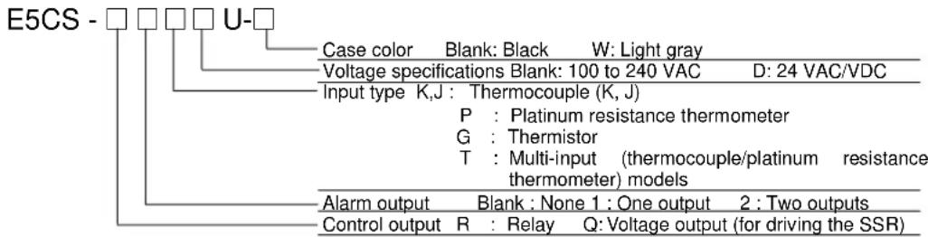
A functional explanation is provided here for illustration, but models are not necessarily available for all possible combinations. Refer to the catalog when ordering.
■ Main Functions
This section introduces the main E5CSV/E5CS-U functions. For details on particular functions and how to use them, refer to SECTION 3 and following sections.
- Input Sensor Types
Thermocouple: K, J, L Platinum resistance: Pt100, JPt100 thermometer Thermistor: E52-THE□□
Multi-input (thermocouple/platinum resistance thermometer) models: K, J, L, T, U, N, R, Pt100, JPt100
- Control Outputs
- A control output can be relay or voltage output, depending on the model.
- Alarms
- Alarms are supported by E5CSV-□1□□-□, E5CSV-□2□□-□, E5CS-□1□□U-□, and E5CS-□2□□U-□. Set the alarm classification and alarm value or the alarm's upper and lower limits. If necessary, a more comprehensive alarm function can be achieved by setting the standby sequence, close in alarm/open in alarm, and alarm latch parameters.
• Control Adjustment - Optimum PID constants can be set easily by performing AT (auto-tuning) or ST (self-tuning).
1.3 Setting Level Configuration and Key Operations
Parameters are divided into groups, each called a “level.” Each of the set values (setting items) in these levels is called a “parameter.”
The parameters on the E5CSV/E5CS-U are divided as follows:
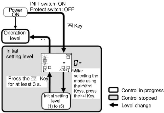
When the power is turned ON, "0" will be displayed for approximately one second.
flowchart
graph TD
    A["Power ON"] --> B["Operation level"]
    B --> C{INIT switch: ON}
    C --> D["Protect switch: OFF"]
    D --> E["Key"]
    E --> F["Initial setting level"]
    F --> G{Press the → Key for at least 3 s.}
    G --> H["Initial setting level (1) to (5)"]
    H --> I["After selecting the mode using the → Keys, press the → Key."]
    style A fill:#f9f,stroke:#333
    style D fill:#ccf,stroke:#333
    style F fill:#cfc,stroke:#333
    style H fill:#fcc,stroke:#333
*1: If there is no input for 5 s or longer, a software reset will be performed to change to the operation level.
| Control in progress | Control stopped | |
| Operation level | ○ | - |
| Initial setting level | - ○ |
O: Can be set.
Control will stop when the operation level is changed to the initial setting level.
- Operation Level
• The operation level is displayed when the power is turned ON.
- Normally, select this level during operation. The PV can be monitored during operation. The SP and alarm values can also be monitored and changed.
- Initial Setting Level
- To display the initial setting level, set the protect switch to OFF and the INIT switch to ON, then turn ON the power while pressing the Key. After turning ON the power, -☐- will be displayed for 5 s. Within these 5 s, select the initial setting level (1) to (5). (All deviation indicators ▲■▼ will flash in the initial setting level selection display.)
- In this level, settings including the hysteresis, output assignment, SP upper and lower limits, and PID constants can be set. Press the ☐ Key from the initial setting level (1) to (5) for at least 3 s. If there is no input within 5 s of -☐- being displayed, a software reset will be performed to change to the operation level.
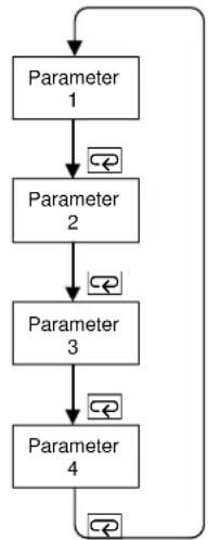
■ Selecting Parameters
- Within each level, the parameter is changed each time the ☐ Key is pressed.
The parameter changes immediately after pressing the ☐ key.
flowchart
graph TD
    A["Parameter 1"] --> B["Parameter 2"]
    B --> C["Parameter 3"]
    C --> D["Parameter 4"]
    D --> E["Feedback Loop"]
■ Fixing Settings
- If the ☐ Key is pressed at the final parameter, the display returns to the top parameter for the current level.
- To change parameter settings, specify the setting using the | or | Key, and either leave the setting for at least 2 s or press the ☑ Key. This fixes the setting.
- When another level is selected after a setting has been changed, the contents of the parameter prior to the change are fixed.
- Be sure to first fix the settings (by pressing the ☑ Key) before turning OFF the power. The settings are sometimes not changed by merely pressing the ⚠ or ⚡ Keys.
1.4 Setting Switches
E5CSV
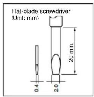
- Insert the tool (refer to the diagram) into the two tool insertion holes (one on the top and one on the bottom) and release the hooks. Then, grip the front panel and pull out towards you to remove it.

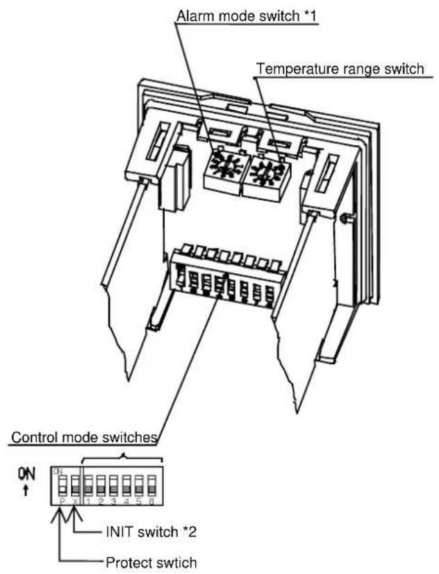
*1. The alarm mode switch is not provided on models without alarms.
*2. The INIT switch is always OFF during normal operation.
- E5CS-U
- Pull forward on the front door opening/closing groove located on the right of the front panel and open the front door. Only open the front door to set the switches. When not setting the switches, always use the E5CS-U with the front door closed.


*1. The alarm mode switch is not provided on models without alarms.
*2. The INIT switch is always OFF during normal operation.

- Protect Switch
- INIT Switch
• Control Mode Switches
- When the protect switch is ON, Up Key and Down Key operations are prohibited to prevent setting mistakes.
- The Mode Key, however, can also be operated even if the protect switch is ON.
(The display can be switched between the process value, set point, alarm value, and input shift value.)
• The default is OFF.
- Turn this switch ON when starting from the initial setting level. For normal operation, make sure this switch is turned OFF.
- Use the control mode switches to make the following operation settings.
| Switch | Function | OFF | ON |
| 1 PID | ON/OFF ON/OFF control 2-PID control | ||
| 2 | Control period | 20 s | 2 s |
| 3 | Direct/reverse operation | Reverse operation | Direct operation |
| 4 | Input shift display | Disabled | Enabled |
| 5 | Temperature Controller selection | Thermocouple: K, J Platinum resistance thermometer: JPt100 Multi-input: Thermocouple input | Thermocouple: K, L Platinum resistance thermometer: Pt100 Multi-input: Platinum resistance thermometer input |
| 6 | Temperature unit | °C | °F |
• All switches are OFF for the default settings.
- The hysteresis when using ON/OFF control is 0.2% FS (multi-input (thermocouple/platinum resistance thermometer) models: 0.1% FS).
- When 2-PID control is set, optimum PID parameters are set automatically and controlled using ST (self-tuning).
- When the input shift display is disabled, the input shift is not displayed, but is enabled.
To disable input shift, set the input shift value to H0.
The default setting for the input shift is H0.
- When using thermistor input, the setting for switch 5 is ignored.
• Temperature Range Switch
- Set the temperature range using the temperature range switch numbers.
- Thermocouple input (E5CSV-□ KJ, E5CS-□ KJU)
| Specifications | Temperature range | Set range | |||||
| °C | °F | ||||||
| K | 0 | 0 | to | 200 | 0 | to | 200 |
| 1 | 0 | to | 300 | 0 | to | 300 | |
| 2 | 0 | to | 400 | 0 | to | 400 | |
| 3 | 0 | to | 500 | 0 | to | 500 | |
| 4 | 0 | to | 600 | 0 | to | 600 | |
| 5 | 0 | to | 999 | 0 | to | 999 | |
| J or L | 6 | 0 | to | 200 | 0 | to | 999 |
| 7 | 0 | to | 300 | 0 | to | 300 | |
| 8 | 0 | to | 400 | 0 | to | 400 | |
| 9 | 0 | to | 500 | 0 | to | 500 | |
* The default is 2.
- Platinum resistance thermometer input (E5CSV-□P, E5CS-□PU)
| Speci-fica-tions | Tem-per-ature range | Setting range | |||||
| °C | °F | ||||||
| JPt100 or Pt100 | 0 | -50 | to | 50 | -50 | to | 50 |
| 1 | 0.0 | to | 50.0 | to.0 | 50.0 | ||
| 2 | -20 | to | 80 | -20 | to | 80 | |
| 3 0.0 | to | 99.9 | 0.0 | to | 99.9 | ||
| 4 | 0 | to | 20 | 0 | to | 20 | |
| 5 | 0 | to | 30 | 0 | to | 30 | |
| 6 | 0 | to | 40 | 0 | to | 40 | |
| 7 | 0 | to | 30 | 0 | to | 60 | |
| 8 | 0 | to | 40 | 0 | to | 80 | |
| 9 | 0.0 | to | 199.9 | 0.0 | to | 199.9 | |
* The default is 3.
- Thermistor input
(E5CSV-□G, E5CS-□GU)
| Specifications | Temperature range | Setting range | |||||
| °C | °F | ||||||
| G | 0 | -50 | to | 50 | -50 | to | 100 |
| 1 | 0 | to | 100 | 0 | to | 200 | |
| 2 | 50 | to | 150 | 100 | to | 300 | |
| 3 | 100 | to | 200 | 200 | to | 400 | |
| 4 | 150 | to | 300 | 300 | to | 600 | |
| 5 | -50 | to | 50 | -50 | to | 100 | |
| 6 | 0 | to | 100 | 0 | to | 200 | |
| 7 | 50 | to | 150 | 100 | to | 300 | |
| 8 | 100 | to | 200 | 200 | to | 400 | |
| 9 | 150 | to | 300 | 300 | to | 600 | |
* The default is 1.
- Multi-input (thermocouple/platinum resistance thermometer) models (E5CSV-□T, E5CS-□TU)
Control mode switch 5: OFF
| Speci-fica-tions | Tem-per-ature range | Setting range | |||||
| °C | °F | ||||||
| K | 0 | -99 | to | 1300 | -99 | to | 1999 |
| 1 | 0.0 | to | 199.9 | 0.0 | to | 199.9 | |
| J | 2 | -99 | to | 850 | -99 | to | 1500 |
| 3 | 0.0 | to | 199.9 | 0.0 | to | 199.9 | |
| L | 4 | -99 | to | 850 | -99 | to | 1500 |
| T | 5 | -99 | to | 400 | -99 | to | 700 |
| 6 | 0.0 | to | 199.9 | 0.0 | to | 199.9 | |
| U | 7 | -99 | to | 400 | -99 | to | 700 |
| N | 8 | -99 | to | 1300 | -99 | to | 1999 |
| R | 9 | 0 | to | 1700 | 0 | to | 1999 |
Control mode switch 5: ON
| Speci-fica-tions | Tem-per-ature range | Setting range | |||||
| °C | °F | ||||||
| Pt100 | 0 | -99 | to | 850 | -99 | to | 1500 |
| 1 | 0.0 | to | 199.9 | 0.0 | to | 199.9 | |
| 2 | -99 | to | 99 | -99 | to | 99 | |
| 3 | 0 | to | 200 | 0 | to | 200 | |
| 4 | 0 | to | 400 | 0 | to | 400 | |
| JPt100 | 5 | -99 | to | 500 | -99 | to | 900 |
| 6 | 0.0 | to | 199.9 | 0.0 | to | 199.9 | |
| 7 | -99 | to | 99 | -99 | to | 99 | |
| 8 | 0 | to | 200 | 0 | to | 200 | |
| 9 | 0 | to | 400 | 0 | to | 400 | |
* The default is 0.
- Alarm Mode Switch
- Select the alarm mode switch number when changing to the alarm mode. This switch is not provided in models without alarms.)
| Set value | Alarm type | Alarm output operation |
| 0,9 Alarm function OFF Output OFF | ||
| 1 Upper- and lower-limit | 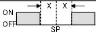 | |
| 2 Upper-limit | 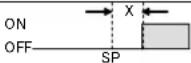 | |
| 3 Lower-limit | 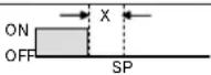 | |
| 4 Upper- and lower-limit range |  | |
| 5 Upper- and lower-limit with standby sequence |  | |
| 6 Upper-limit with standby sequence |  | |
| 7 Lower-limit with standby sequence |  | |
| 8 Absolute-value upper-limit |  | |
* Alarm values 1 to 7: Set the deviation from the SP (set point) in the alarm value (X).
Alarm 8: Set the absolute value from 0^/^ in the alarm value (Y).
* The default is 2 (upper-limit alarm).
Section 2 Preparations
2.1 Installation 2-2
■ External Dimensions (Unit: mm) ......2-2
• E5CSV 2-2
• E5CS-U 2-2
■ Panel Cutout Dimensions (Unit: mm) ......2-2
- E5CSV and E5CS-U 2-2
■ Mounting....2-3
• E5CSV 2-3
• E5CS-U 2-3
- Mounting to the Panel 2-3
- Mounting the Terminal Cover ....2-3
■ Removing the E5CSV from the Case ......2-3
2.2 Wiring Terminals 2-5
■ Terminal Arrangement....2-5
• E5CSV....2-5
• E5CS-U (Without Alarms) 2-5
(With Alarms)....2-5
■ Precautions when Wiring ....2-6
■ Wiring ....2-6
- Power Supply....2-6
- Input....2-6
• Control Outputs ......2-7
- Alarm Outputs 1 and 2 ....2-7
2.1 Installation
■ External Dimensions (Unit: mm)
• E5CSV
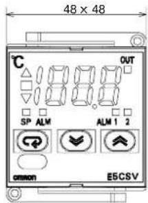
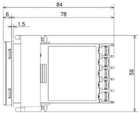
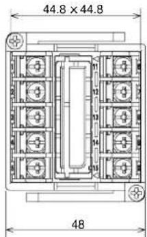
• E5CS-U


■ Panel Cutout Dimensions (Unit: mm)
• E5CSV and E5CS-U
Individual Mounting

Group Mounting
(48 · Number of Units - 2.5) _0^+1.0
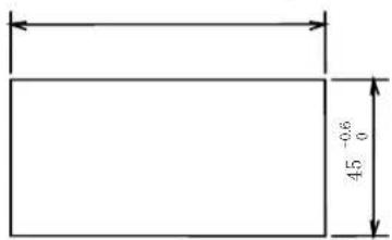
The recommended panel thickness is 1 to 4 mm.
• Waterproofing is not possible when group mounting several Controllers.
- When group mounting several Controllers, ensure that the ambient temperature does not exceed the specifications due to heat generated by the Controllers.
• Group mounting is possible in one direction only, either vertical or horizontal.
■ Mounting
For the Wiring Socket, separately purchase the P2CF-08 or P3G-08 for models without alarms, or the P2CF-11 or P3GA-11 for models with alarms.
•E5CSV •E5CS-U

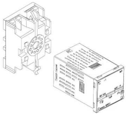
natural_image
Technical line drawing of a mechanical component and its corresponding electronic device (no text or symbols visible)- Mounting to the Panel
(1) For waterproof mounting, waterproof packing must be installed on the Controller. Waterproofing is not possible when group mounting several Controllers. (E5CSV only)
(2) Insert the E5CSV/E5CS-U into the mounting hole in the panel.
(3) Push the adapter from the terminals up to the panel, and temporarily fasten the E5CSV/E5CS-U.
(4) Tighten the two fastening screws on the adapter. Alternately tighten the two screws little by little to maintain a balance. Tighten the screws to a torque of 0.29 to 0.39 N·m.
- Mounting the Terminal Cover
For the E5CSV, make sure that the "UP" mark is facing up, and then fit the terminal cover into the holes on the top and bottom.
* Order the E53-COU10 Terminal Cover separately.
■ Removing the E5CSV from the Case
The Temperature Controller can be removed from the case to perform maintenance without removing the terminal leads. Only E5CSV can be removed from the case. The E5CS-U cannot be removed from the case.

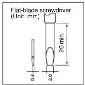
(1) Insert the tool into the two tool insertion holes (one on the top and one on the bottom) and release the hooks.
(2) Insert the tool in the gap between the front panel and rear case, and pull out the front panel slightly. Grip the front panel and pull out fully. Be sure not to impose excessive force on the panel.
(3) When inserting the E5CSV, check to make sure that the sealing rubber is in place and push the E5CSV toward the rear case until it snaps into position. While pushing the E5CSV into place, push down on the hooks on the top and bottom surfaces of the rear case so that the hooks are securely locked in place. Make sure that electronic components do not come into contact with the case.
* Do not remove the terminal block. Doing so will result in malfunction or failure.
2.2 Wiring Terminals
■ Terminal Arrangement
• E5CSV
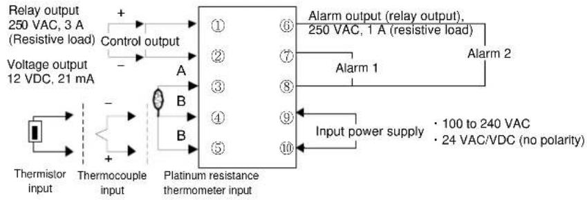
flowchart
graph LR
    A["Thermistor input"] --> B["Thermocouple input"]
    B --> C["Platinum resistance thermometer input"]
    C --> D["Control output"]
    D --> E["Relay output 250 VAC, 3 A (Resistive load)"]
    D --> F["Voltage output 12 VDC, 21 mA"]
    C --> G["Alarm 1"]
    C --> H["Alarm 2"]
    C --> I["Input power supply"]
    C --> J["• 100 to 240 VAC\n• 24 VAC/VDC (no polarity)"]
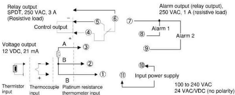
• E5CS-U (Without Alarms)

flowchart
graph TD
    A["Thermistor input"] --> B["Thermocouple input"]
    B --> C["Platinum resistance thermometer input"]
    C --> D["Control output"]
    D --> E["Relay output SPDT, 250 VAC, 3 A (resistive load)"]
    D --> F["Voltage output 12 VDC, 21 mA"]
    C --> G["Input power supply 100 to 240 VAC, 24 VAC/VDC (no polarity)"]
    style A fill:#f9f,stroke:#333
    style B fill:#f9f,stroke:#333
    style C fill:#f9f,stroke:#333
    style D fill:#ccf,stroke:#333
    style E fill:#ccf,stroke:#333
    style F fill:#ccf,stroke:#333
(With Alarms)
* Purchase the P2CF-08 or P3G-08 wiring socket separately.
flowchart
graph TD
    A["Thermistor input"] --> B["Thermocouple input"]
    B --> C["Control output"]
    C --> D["Relay output SPDT, 250 VAC, 3 A (Resistive load)"]
    D --> E["+"]
    E --> F["Voltage output 12 VDC, 21 mA"]
    F --> G["Control output"]
    G --> H["+"]
    H --> I["Platinum resistance thermometer input"]
    I --> J["Control output"]
    J --> K["Relay output"]
    K --> L["Alarm 1"]
    L --> M["Alarm 2"]
    M --> N["Input power supply"]
    N --> O["100 to 240 VAC 24 VAC/VDC (no polarity)"]
* Purchase the P2CF-11 or P3GA-11 wiring socket separately.
■ Precautions when Wiring
- Separate input leads and power lines in order to prevent external noise.
- Use AWG24 (cross-sectional area: 0.205 mm ^2 ) to AWG18 (cross-sectional area: 0.832 mm ^2 ) twisted-pair cable (stripping length: 5 to 6 mm).
• Use crimp terminals when wiring the terminals. - Tighten the terminal screws to a torque of 0.74 to 0.90 N·m. The tightening torque for E5CS-U is 0.5 N·m.
• Use the following types of crimp terminals for M3.5 screws.

■ Wiring
In the connection diagrams, the left side of the terminal numbers represents the inside of the Controller and the right side represents the outside.
- Power Supply
- With the E5CSV, connect to terminals 9 and 10. For the E5CS-U with alarms, connect to terminals 10 and 11, and for E5CS-U models without alarms, connect to terminals 7 and 8. The following table shows the specifications.
Power Consumption
| Input power supply E5 | CSV | E5CS-U | |
| 100 to 240 VAC, 50/60 Hz | 5 VA | 5 VA | |
| 24 VAC, 50/60 Hz | 3 VA | 3 VA | |
| 24 VDC (no polarity) | 2 W | 2 W |
- For the E5CS-U, standard insulation is applied between the input power supply and the I/O sections. If reinforced insulation is required, connect the input and output terminals to a device without any exposed current-carrying parts or to a device with standard insulation suitable for the maximum operating voltage of the power supply I/O section.
- For the E5CSV, reinforced insulation is applied between the input power supply, relay outputs, and other terminals.
- Input
- Make the connections as shown below, using terminals 3 to 5 for the E5CSV, and terminals 1 to 3 for the E5CS-U, and matching the input types.

- Control Outputs
- Outputs are sent from terminals 1 and 2 with the E5CSV, and from terminals 4 to 6 with the E5CS-U. The following diagrams show the available outputs and their internal equalizing circuits.


• The following table shows the specifications for each output type.
| Output type | Specifications |
| Relay | 250 VAC, 3A (resistive load), electrical durability: 100,000 operations |
| Voltage (PNP) | PNP type, 12 VDC±15%, 21 mA (with short-circuit protection) |
- A voltage output (control output) is not electrically isolated from the internal circuits. When using a grounding Sensor, do not connect any of the control output terminals to the ground. (If control output terminals are connected to the ground, errors will occur in the measured temperature values as a result of leakage current.)
• Alarm Outputs 1 and 2
- With the E5CSV-□1□□-□, alarm output 1 (ALM1) is output across terminals 7 and 8.
- On the E5CSV-□2□□-□, alarm output 1 (ALM1) is output across terminals 7 and 8, and alarm output 2 (ALM2) is output across terminals 6 and 8.
- With the E5CS-□1□□U-□, alarm output 1 (ALM1) is output across terminals 7 and 8.
- On the E5CS-☐2☐☐U-☐, alarm output 1 (ALM1) is output across terminals 7 and 8, and alarm output 2 (ALM2) is output across terminals 7 and 9.
- The following diagrams show the internal equalizing circuits for alarm outputs 1 and 2.


• The relay specifications are as follows: SPST-NO, 250 VAC, 1 A (resistive load)
Section 3 Basic Operations
3.1 Setting the Input Type 3-2
■ Input Type....3-2
- Thermocouple....3-2
- Platinum Resistance Thermometer....3-2
- Thermistor....3-3
- Multi-input (Thermocouple/Platinum Resistance
Thermometer) Models....3-3
3.2 Selecting the Temperature Unit 3-4
- Temperature Unit....3-4
3.3 Selecting PID Control or ON/OFF Control.... 3-5
- 2-PID Control....3-5
- ON/OFF Control....3-5
3.4 Setting Output Specifications 3-6
■ Control Period....3-6
■ Direct/Reverse Operation....3-6
3.5 Setting the Set Point (SP).... 3-7
■ Changing the SP ....3-7
3.6 Using ON/OFF Control 3-8
■ ON/OFF Control 3-8
- Hysteresis....3-8
3.7 Determining PID Constants (AT, ST, Manual Setup) 3-9
■ AT (Auto-tuning)....3-9
- AT Operations....3-9
■ ST (Self-tuning) 3-10
- Startup Conditions....3-10
• ST Stable Range....3-11
■ Manual Setup 3-12
3.8 Alarm Outputs.... 3-14
■ Alarm Types....3-14
■ Alarm Values ....3-14
3.9 Shifting Input Values 3-16
■ Shifting Inputs....3-16
- Shift Method....3-17
3.1 Setting the Input Type
The E5CS is available in models with thermocouple input, models with platinum resistance thermometer input, thermistor input, and multi-input (thermocouple/platinum resistance thermometer) models. The type of Sensor that can be used depends on the model. Confirm the model that was purchased, and set the Sensor to be used and the temperature range switch.
■ Input Type
- Thermocouple
| Specifications | Temper- ature range | Input temperature range | |||||
| K | 0 | 0 | to | (°C)200 / 0 to | 200 (°F) | ||
| 1 0 | to | 300 | (°C) / 0 to | 300 (°F) | |||
| 2 0 | to | 400 | (°C) / 0 to | (°400 | |||
| 3 | 0 | to | (°C)500 / 0 to | (°500 | |||
| 4 | 0 | to | (°C)500 / 0 to | (°600 | |||
| 5 0 | to | 999 | (°C) / 0 to | 999 (°F) | |||
| J/L | 6 0 | to | 200 | (°C) / 0 to | 999 (°F) | ||
| 7 | 0 | to | (°C)300 / 0 to | (°800 | |||
| 8 | 0 | to | (°C)400 / 0 to | (°400 | |||
| 9 0 | to | 500 | (°C) / 0 to | 500 (°F) | |||
• The default is 2.
• The control range is -10% to 10% FS for each temperature range.
- J/L can be selected using the control mode switch 5. J is set when the switch is OFF, and L is set when the switch is ON.
- Platinum
Resistance Thermometer
| Specifications | Temper- ature range | Input temperature range | |||||||
| JPt100/Pt100 | 0 | -50 | to | 50 (°C) | / | -50 | to | 50 | (°F) |
| 1 | 0.0 | to | 50.0(°C) | / | 0.0 | to | 50.0 | (°F) | |
| 2 | -20 | to | 80 (°C) | / | -20 | to | 80 | (°F) | |
| 3 | 0.0 | to | 99.9 (°C) | / | 0.0 | to | 99.9 | (°F) | |
| 4 | 0 | to | 200(°C) | / | 0 | to | 200(°F) | ||
| 5 | 0 | to | 300(°C) | / | 0 | to | 300(°F) | ||
| 6 | 0 | to | 400(°C) | / | 0 | to | 400(°F) | ||
| 7 | 0 | to | 300(°C) | / | 0 | to | 600(°F) | ||
| 8 | 0 | to | 400(°C) | / | 0 | to | 800(°F) | ||
| 9 | 0.0 | to | 199.0(°C) | / | 0.0 | to | 199.9 | (°F) | |
• The default is 3.
• The control range is -10% to 10% FS for each temperature range.
- JPt100/Pt100 can be selected using the control mode switch 5. JPt100 is set when this switch is OFF, and Pt100 is set when this switch is ON.
- If unit is changed to 1 degree when the SP and alarm value for the temperature range are displayed in 0.1-units from 0.0 to 199.9, 0.0 to 99.9 or 0.0 to 50.0, the values will be multiplied by 10 (e.g., 0.5 becomes 5). If the unit is changed in the reverse direction, the values will be divided by 10. After changing the range, reset the Controller.
- Thermistor
| Specifications | Temper- ature range | Input temperature range | |||||||
| THE | 6 KΩ (0°C) | 0 | -50 | to | (50) | / | -50 | to | 100 (°F) |
| 6 KΩ (0°C) | 1 0 | to | 100 | (°C) | / | 0 | to | (°200 | |
| 30 KΩ (0°C) | 2 | 50 | to | (°C) | / | 100 | to | 300 | |
| 550 Ω (200°C) | 3 | 100 | to | (200) | / | 200 | to | 400 | |
| 4 KΩ (200°C) | 4 | 150 | to | (300) | / | 300 | to | 600 | |
| 6 KΩ (0°C) | 5 | -50 | to | (50) | / | -50 | to | 100 (°F) | |
| 6 KΩ (0°C) | 6 | 0 | to | (°000) | / | 0 | to | (°200 | |
| 30 KΩ (0°C) | 7 | 50 | to | (°C) | / | 100 | to | 300 | |
| 550 Ω (200°C) | 8 | 100 | to | (200) | / | 200 | to | 400 | |
| 4 KΩ (200°C) | 9 | 150 | to | (300) | / | 300 | to | 600 | |
- The default is 1. If the setting is changed to a temperature range that goes below 0^ , the minimum value inside the SP range will be automatically used as the SP. The SP will be displayed when the power is turned ON.
• The control range depends on the setting numbers, as follows:
Input setting numbers 0 and 5: -50 to +60°C
Input setting numbers 2 and 7: 0 to 160°C or 35 to 320°F
Input setting numbers 3 and 8: 0 to 210°C or 35 to 420°F
Input setting numbers 4 and 9: 25 to 315°C or 80 to 630°F
Others: -10% to 10% FS
- Multi-input (Thermocouple/Platinum Resistance Thermometer) Models
Control Mode Switch 5: OFF
| Specifications | Temper- ature range | Input temperature range | ||||||||
| K | 0 | -99 | to | 1300 | (°C) | / | -99 | to | 1999 | (°F) |
| 1 | 0.0 | to | 199.9 | (°C) | / | 0.0 | to | 199.9 | (°F) | |
| J | 2 | -99 | to | 850 | (°C) | / | -99 | to | 1500 | (°F) |
| 3 | 0.0 | to | 199.9 | (°C) | / | 0.0 | to | 199.9 | (°F) | |
| L | 4 | -99 | to | 850 | (°C) | / | -99 | to | 1500 | (°F) |
| T | 5 | -99 | to | 400 | (°C) | / | -99 | to | 700 | (°F) |
| 6 | 0.0 | to | 199.9 | (°C) | / | 0.0 | to | 199.9 | (°F) | |
| U | 7 | -99 | to | 400 | (°C) | / | -99 | to | 700 | (°F) |
| N | 8 | -99 | to | 1300 | (°C) | / | -99 | to | 1999 | (°F) |
| R | 9 | 0 | to | 1700(°C) | / | 0 | to | 1999 | (°F) | |
Control Mode Switch 5: ON
| Specifications | Temper- ature range | Input temperature range | ||||||||
| Pt100 | 0 | -99 | to | 850 | (°C) | / | -99 | to | 1500 | (°F) |
| 1 | 0.0 | to | 199.9 | (°C) | / | 0.0 | to | 199.9 | (°F) | |
| 2 | -99 | to | 99 | (°C) | / | -99 | to | 99 | (°F) | |
| 3 | 0 | to | 200 | (°C) | / | 0 | to | 200 | (°F) | |
| 4 | 0 | to | 400 | (°C) | / | 0 | to | 400 | (°F) | |
| JPt100 | 5 | -99 | to | 500 | (°C) | / | -99 | to | 900 | (°F) |
| 6 | 0.0 | to | 199.9 | (°C) | / | 0.0 | to | 199.9 | (°F) | |
| 7 | -99 | to | 99 | (°C) | / | -99 | to | 99 | (°F) | |
| 8 | 0 | to | 200 | (°C) | / | 0 | to | 200 | (°F) | |
| 9 | 0 | to | 400 | (°C) | / | 0 | to | 400 | (°F) | |
• The default is 0.
• The control range is ±20^ or ±40^ of the input temperature range.
- If unit is changed to 1 degree when the SP and alarm value for the temperature range are displayed in 0.1-units from 0.0 to 199.9, 0.0 to 99.9 or 0.0 to 50.0, the values will be multiplied by 10 (e.g., 0.5 becomes 5). If the unit is changed in the reverse direction, the values will be divided by 10. After changing the range, reset the Controller.
3.2 Selecting the Temperature Unit
- Temperature Unit
- Select the temperature unit as either °C or °F using the control mode switch 6.
• The default is OFF (°C).
3.3 Selecting PID Control or ON/OFF Control
Two control methods are supported: 2-PID control and ON/OFF control. Switching between 2-PID control and ON/OFF control is performed using the control mode switch 1. When this parameter is set to ON, 2-PID control is selected, and when it is set to OFF, ON/OFF control is selected. The default is OFF (ON/OFF control).
- 2-PID Control
PID control is set by AT (auto-tuning), ST (self-tuning), or manual setting.
For PID control, set the PID constants in the “proportional band” (P), “integral time” (I), and “derivative time” (D) parameters.
- ON/OFF Control
In ON/OFF control, the control output is turned ON when the process value is lower than the current set point, and the control output is turned OFF when the process value is higher than the current set point (reverse operation).
3.4 Setting Output Specifications
■ Control Period
- Set the output period (control period). Though a shorter period provides better control performance, it is recommended that the control period be set to 20 seconds or longer for a relay output to preserve the service life of the relay. After the settings have been made in the initial setup, readjust the control period, as required, by means such as trial operation.
- The control period can be set to either 2 s or 20 s using the control mode switch 2. The default is OFF (20 s).
- The control period can also be set to 6 s or 60 s by changing the control period setting in the initial setting level (1).
■ Direct/Reverse Operation
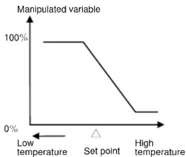
- "Direct operation" increases the manipulated variable whenever the process value increases. "Reverse operation" decreases the manipulated variable whenever the process value increases.

line
| Temperature Level | Manipulated variable | | ----------------- | -------------------- | | Low | 0% | | Set point | 100% | | High | 100% |Direct operation
line
| Temperature Level | Manipulated variable | | ----------------- | -------------------- | | Low | 100% | | Set point | 100% | | High | 0% |Reverse operation
For example, when the process value (PV) is lower than the set point (SP) in a heating control system, the manipulated variable increases according to the difference between the PV and SP. Accordingly, reverse operation is used in a heating control system. Direct operation is used in a cooling control system, in which the operation is the opposite of a heating control system.
- Set using the control mode switch 3. The default is OFF (reverse operation).
3.5 Setting the Set Point (SP)
The operation level is displayed when the power is turned ON. When the ☑ Key is used to light the SP indicator in the display, the set point is displayed.
■ Changing the SP
- To change the set point, press the ▲ or √ Key while SP is lit on the display, and set the desired set value. The new set point is selected two seconds after the new value is specified.
• The set point cannot be changed when the protect switch is ON. - The setting window for the set point (SP mode) can be set as the default window when the power is turned ON using the "PV/SP display" parameter in the initial setting level (1).
Operating Procedure
In this example, the set point is changed from 0^ C to 200^ C.

flowchart
graph TD
    A["Power ON"] --> B["Process value (PV)"]
    B --> C["SP mode Set point"]
    C --> D["Output Display"]
    D --> E["SP ALM ALM1 2"]
    E --> F["SP ALM ALM1 2"]
    F --> G["SP ALM ALM1 2"]
    G --> H["SP ALM ALM1 2"]
    H --> I["SP ALM ALM1 2"]
    I --> J["SP ALM ALM1 2"]
    J --> K["SP ALM ALM1 2"]
    K --> L["SP ALM ALM1 2"]
    L --> M["SP ALM ALM1 2"]
    M --> N["SP ALM ALM1 2"]
    N --> O["SP ALM ALM1 2"]
    O --> P["SP ALM ALM1 2"]
    P --> Q["SP ALM ALM1 2"]
    Q --> R["SP ALM ALM1 2"]
    R --> S["SP ALM ALM1 2"]
    S --> T["SP ALM ALM1 2"]
    T --> U["SP ALM ALM1 2"]
    U --> V["SP ALM ALM1 2"]
    V --> W["SP ALM ALM1 2"]
    W --> X["SP ALM ALM1 2"]
    X --> Y["SP ALM ALM1 2"]
    Y --> Z["SP ALM ALM1 2"]
    Z --> AA["SP ALM ALM1 2"]
    AA --> AB["SP ALM ALM1 2"]
    AB --> AC["SP ALM ALM1 2"]
    AC --> AD["SP ALM ALM1 2"]
    AD --> AE["SP ALM ALM1 2"]
    AE --> AF["SP ALM ALM1 2"]
    AF --> AG["SP ALM ALM1 2"]
    AG --> AH["SP ALM ALM1 2"]
    AH --> AI["SP ALM ALM1 2"]
    AI --> AJ["SP ALM ALM1 2"]
    AJ --> AK["SP ALM ALM1 2"]
    AK --> AL["SP ALM ALM1 2"]
    AL --> AM["SP ALM ALM1 2"]
    AM --> AN["SP ALM ALM1 2"]
    AN --> AO["SP ALM ALM1 2"]
    AO --> AP["SP ALM ALM1 2"]
    AP --> AQ["SP ALM ALM1 2"]
    AQ --> AR["SP ALM ALM1 2"]
    AR --> AS["SP ALM ALM1 2"]
    AS --> AT["SP ALM ALM1 2"]
    AT --> AU["SP ALM ALM1 2"]
    AU --> AV["SP ALM ALM1 2"]
    AV --> AW["SP ALM ALM1 2"]
    AW --> AX["SP ALM ALM1 2"]
    AX --> AY["SP ALM ALM1 2"]
- Display the set point (SP mode) using the ☐ Key.
- Use the ▲ and ▼ Keys to set the set point to 200.
3.6 Using ON/OFF Control
In ON/OFF control, the control output turns OFF when the temperature being controlled reaches the preset set point. When the manipulated variable turns OFF, the temperature begins to fall and the control turns ON again. This operation is repeated over a certain temperature range. At this time, the amount that the temperature must fall before control turns ON again is determined by the "hysteresis" parameter. Also, what direction the manipulated variable must be adjusted in response to an increase or decrease in the process value is determined by the "direct/reverse operation" parameter.
■ ON/OFF Control
- Hysteresis
- Switching between 2-PID control and ON/OFF control is performed using the control mode switch 1. When this parameter is set to ON, 2-PID control is selected, and when it is set to OFF, ON/OFF control is selected. The default is OFF (ON/OFF control).
- With ON/OFF control, hysteresis is used to stabilize operation when switching between ON and OFF. The hysteresis width is referred to as "hysteresis."
- Set the hysteresis in the "hysteresis" parameter in the initial setting level (1).
Reverse operation

3.7 Determining PID Constants (AT, ST, Manual Setup)
■ AT (Auto-tuning)
- AT Operations
- When AT is executed, the optimum PID constants for the set point at that time are set automatically. A method (called the limit cycle method) for forcibly changing the manipulated variable and finding the characteristics of the control target is employed.
• Auto-tuning (AT) cannot be used during ON/OFF control. - The AT results are reflected in the “proportional band” (P), “integral time” (I), and “derivative time” (D) parameters in the initial setting level (2).
With PV Display
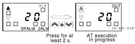
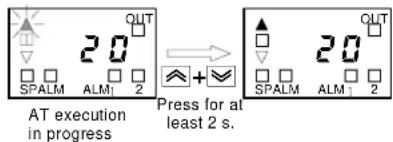
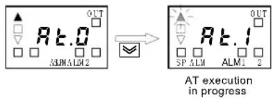
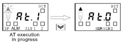
AT (auto-tuning) is executed by pressing the ▲ and ▼ Keys for at least 2 s while the PV is displayed. The deviation indicators flash during auto-tuning (AT) execution. AT will be cancelled by performing the same operation that AT is executing during AT operation. Flashing stops when AT is completed.
AT execution
AT cancelled
*: One of the deviation indicators (▲■▼) will flash.
Without PV Display
The “AT execute/cancel” parameter is displayed in the operation level. Auto-tuning (AT) starts when the “AT execute/cancel” parameter is set to 1. Auto-tuning (AT) is cancelled when the “AT execute/cancel” parameter is set to 0 during auto-tuning. When auto-tuning is completed, the “AT execute/cancel” parameter is automatically set to 0.
AT execution
AT cancelled
*: One of the deviation indicators (▲■▼) will flash.
■ST (Self-tuning)
ST (self-tuning) is a function that finds PID constants by using step response tuning (SRT) when Controller operation begins or when the set point is changed.
Once the PID constants have been calculated, ST is not executed when the next control operation is started as long as the set point remains unchanged.
When the ST function is in operation, be sure to turn ON the power supply of the load connected to the control output simultaneously with or before starting Controller operation.
- Startup Conditions
Self-tuning by step response tuning (SRT) is started when the following conditions are met after program execution is started and the set point is changed.
| At start of operation When set point is changed | |
| 1. The set point at the start of operation differs from the set point when the previous SRT was executed. *12. The difference between the temperature at the start of operation and the set point is greater than both the following: (Present proportional band · 1.27 + 4°C) and the ST stable range.3. The temperature at the start of operation is lower than the set point during reverse operation, and is larger than the set point during direct operation.4. There is no reset from input errors. | 1. The set point after changing differs from the set point when the previous SRT was executed. *12. The set point change width is greater than both of the following: (Present proportional band · 1.27 + 4°C) and the ST stable range.3. During reverse operation, the new set point is larger than the set point before the change; and during direct operation, the new set point is smaller than the set point before the change.4. The temperature is stable. *2 (Equilibrium with the output amount at 0% when the power is turned ON is also all right. *3 |
*1. The previous SRT-implemented set point is the set point that was used for calculating the PID constants for the previous SRT.
*2. In this state, the measurement point is within the ST stable range.
*3. In this state, the change width of the PV every 60 seconds is within the ST stable range or less.
When auto-tuning (AT) is executed, PID constants are not changed by self-tuning (ST) for the present set point.
• ST Stable Range Operating Procedure

flowchart
graph TD
    A["Initial setting level (1)"] --> B["SP mode"]
    B --> C["ALM mode"]
    C --> D["IS mode\nST stable range"]
    D --> E["OUT 20 1 2 ALM ALM SP"]
The ST stable range determines the set value under which ST (self-tuning) functions operate. This procedure sets the ST stable range to 20^ C.
- Press the ☐ Key from the initial setting level (1) and select "ST stable range" (IS mode).
- Use the ▲ and ▼ Keys to set the parameter to 20^ C.
■ Manual Setup
Operating Procedure
The manual settings for PID constants are performed separately in the “proportional band” (P), “integral time” (I), and “derivative time” (D) parameters in the initial setting level (2). When PID constants are set manually, the tuning setting enabled in the initial setting level (1) is automatically changed to AT (auto-tuning), and ST (self-tuning) is disabled.
In this example, the “proportional band” parameter is set to 10, the “integral time” parameter to 250, and the “derivative time” parameter to 45.

flowchart
graph TD
    A["Initial setting level (2)"] --> B["OUT □ 2 ALM ALM SP"]
    B --> C["SP mode Proportional band"]
    C --> D["OUT □ 8 2 ALM ALM SP"]
    D --> E["ALM mode Integral time"]
    E --> F["OUT □ 10 2 ALM ALM SP"]
    F --> G["ALM mode √ 233"]
    G --> H["OUT □ 250 2 ALM ALM SP"]
    H --> I["IS mode Derivative time"]
    I --> J["OUT □ 40 2 ALM ALM SP"]
    J --> K["ALM mode √ 45"]
- Select the initial setting level (2).
- Press the ☐ Key to select the "proportional band" (SP mode) parameter.
- Use the ⚠️ and ⚡️ Keys to set 10.
- Press the ☐ Key to select the "integral time" (ALM mode) parameter.
- Press the ▲ or ▼ Key to set 250.
- Press the ☐ Key to select the "derivative time" (IS mode) parameter.
- Press the ▲ or ▼ Key to set 45.

Proportional Action When PID constants I (integral time) and D (derivative time) are set to 0, control is executed according to proportional action. As the default, the center value of the proportional band becomes the set point.
- When P (Proportional Band) Is Adjusted
| Increasing P |  | The curve rises gradually, and a long stabilization time is created, but overshooting is prevented. |
| Decreasing P | 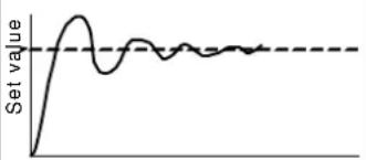 | Overshooting and hunting occur, but the set value is quickly reached and the temperature stabilizes. |
- When (Integral Time) Is Adjusted
| Increasing I |  | It takes a long time to reach the set point.It takes time to achieve a stable state, but overshooting, undershooting, and hunting are reduced. |
| Decreasing I |  | Overshooting and undershooting occur.Hunting occurs.The Controller starts up faster. |
- When D (Derivative Time) Is Adjusted
| Increasing D |  | Overshooting, undershooting, and stabilization times are reduced, but fine hunting occurs on changes in the curve itself. |
| Decreasing D | 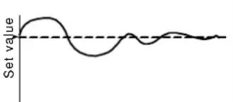 | Overshooting and undershooting increase, and it takes time to return to the set point. |
3.8 Alarm Outputs
- Alarms can be used with E5CS□1□□-□ (one alarm point), E5CS□2□□-□ (two alarm points), E5CS□1□□U-□ (one alarm point), and E5CS□2□□U-□ (two alarm points).
Alarm output conditions are determined by a combination of the "alarm type" and "alarm value".
- The alarm type and alarm value are explained below.
■ Alarm Types
| Set value | Alarm type | Alarm output operation |
| 0,9 | Alarm function OFF | Output OFF |
| 1 | Upper- and lower-limit |  |
| 2 | Upper-limit |  |
| 3 | Lower-limit |  |
| 4 | Upper- and lower-limit range |  |
| 5 | Upper- and lower-limit with standby sequence |  |
| 6 | Upper-limit with standby sequence |  |
| 7 | Lower-limit with standby sequence | 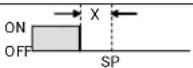 |
| 8 | Absolute-value upper-limit | 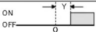 |
* Alarm values 1 to 7: Set the deviation from the SP (set point) in the alarm value (X).
Alarm 8: Set the absolute value from 0^ C/ ^ F in the alarm value (Y).
* The default is 2 (Upper-limit alarm).
* Set the alarm type for alarm 1 (alarm 1 type) using the alarm mode switch.
* Set the alarm type for alarm 2 (alarm 2 type) in the “alarm 2 type” parameter of the initial setting level (5).
■ Alarm Values
- Alarm values are indicated by "X" and "Y" in the previous table of alarm types.
- The alarm value 1 setting is set in ALM mode, and alarm value 2 is set in ALM2 mode. In ALM mode, ALM is lit in the display, and in ALM2 mode, ALM is flashing in the display.
Operating Procedure
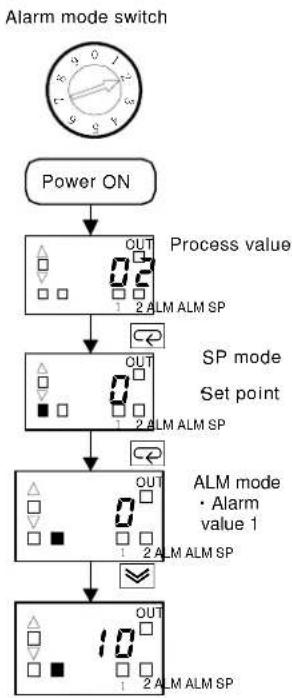
This procedure sets alarm 1 as an upper-limit alarm. The related parameters and settings are shown below. The alarm is output when the set point exceeds 10^ C. (In this example, the temperature unit is ^ C.)
Alarm 1 type = 2 (upper limit)
Alarm value 1 = 10
flowchart
graph TD
    A["Alarm mode switch"] --> B["Power ON"]
    B --> C["Process value OUT 2 ALM ALM SP"]
    C --> D["SP mode OUT 2 ALM ALM SP"]
    D --> E["Set point OUT 2 ALM ALM SP"]
    E --> F["ALM mode ALM mode - Alarm value 1 OUT 2 ALM ALM SP"]
    F --> G["ALM mode ALM mode - Alarm value 1 OUT 2 ALM ALM SP"]
- Set the alarm mode switch to 2 and then turn ON the power.
- Press the ☑ Key in the operation level and select the "alarm value 1" (ALM mode) parameter.
- Use the ⬆ Key to set the parameter to 10.
3.9 Shifting Input Values
■ Shifting Inputs
When the control mode switch 4 is set to ON, the input shift value is displayed in the operation level and the shift can be added to the input. When the control mode switch 4 is set to OFF (no input shift display), the input shift is not displayed but the shift value is enabled. To disable input shift, set the input shift value to H0. The shift range is set using PV and SP setting units, as shown in the following table.
| Setting unit | 1°C | 0.1°C |
| Shift range | -99 to +99°C | -9.9 to +9.9°C |
| Input shift display | L99 to H99 | L9.9 to H9.9 |
- The value set for the “input shift” parameter (operation level) is applied to each point in the entire temperature input range. For example, if the input shift value is set to 2°C, the process value is treated as 102°C after the input shift is applied when the measured process value (before input shift) is 100°C.

Operating Procedure
The following procedure shows how to shift a K Sensors by 1°C.

flowchart
graph TD
    A["Power ON"] --> B["Process value"]
    B --> C["SP mode<br>• Set point"]
    C --> D["ALM mode<br>Alarm value 1"]
    D --> E["ALM2 mode<br>• Alarm value 2"]
    E --> F["IS mode<br>• Input shift value"]
    F --> G["Output"]
Operation
Level
- Press the ☐ Key to select the "input shift value" (IS mode (1)) parameter.
- Press the ▲ or ▼ Key to set 1.
- Shift Method
- Make sure that the control target temperature (C) and Controller temperature (B) match, with the control target temperature near the set point.
- Check the control target temperature (B) and the Controller readout (A).
Subtract the Controller readout temperature (A) from the control target temperature (B)
Set the result as the input shift value. The shift is illustrated below.
- After setting the input shift values, check the Controller readout (A) and the control target temperature (B). If they are almost the same, this completes shifting the temperature input.

line
| Condition | Temperature (B) | Readout (A) | | --------------------- | --------------- | ----------- | | Before shifting | 110 | - | | After shifting | 120 | - | | Input shift value | 10 | - |Input Shift
Section 4 Operations for Applications
4.1 Moving to the Initial Setting Level 4-2
4.2 Assigning Outputs 4-3
■ Output Assignment.... 4-3
4.3 Alarm Functions 4-4
■ Alarm Hysteresis 4-4
■ Standby Sequence 4-4
■ Alarm Latch 4-4
- Alarm Latch Clear Operation....4-4
■ Close in Alarm/Open in Alarm 4-5
- Summary of Alarm Operation ....4-5
4.4 Setting the SP Upper and Lower Limit Values.... 4-6
■ Set Point Limiter 4-6
■ Setting 4-6
4.5 Alarm Delays 4-8
■ Alarm Delays 4-8
- Operation of Alarm ON and OFF Delays (for an Upper-limit Alarm)....4-8
- Parameters Related to Alarm Delays......4-9
4.1 Moving to the Initial Setting Level
To move to the initial setting level, turn OFF the protect switch, turn ON the INIT switch, and then hold down the Key while turning ON the power. The status of the control mode switches 1 to 6 is ignored.
- From the initial setting level selection display (-0-), press the / Keys and select the initial setting level. (If no key input is entered within 5 s, a software reset is executed and the display moves to the operation level.) All deviation indicators ( ) will flash in the initial setting level selection display.
- Press the ☐ Key and move to the applicable initial setting level display.
- Press the ☐ Key for at least 3 s to return to the initial setting level selection display.

flowchart
graph TD
    A["Initial setting level"] --> B["Power ON"]
    B --> C["Initial setting level selection display (If no key input is entered within 5 s, a software reset is executed and the display moves to the operation level.)"]
    C --> D["Operation level"]
    D --> E["Press the ▲ Key for at least 3 s."]
    E --> F["Press the ▼ Key and move to the applicable initial setting level display. Initial setting level selection display"]
    F --> G["Output: SP ALM 1 ALM 2 OUT"]
    F --> H["Output: SP ALM 1 ALM 2 OUT"]
    F --> I["Output: SP ALM 1 ALM 2 OUT"]
    F --> J["Output: SP ALM 1 ALM 2 OUT"]
    F --> K["Output: SP ALM 1 ALM 2 OUT"]
    style A fill:#f9f,stroke:#333
    style B fill:#ccf,stroke:#333
    style C fill:#cfc,stroke:#333
    style D fill:#fcc,stroke:#333
    style E fill:#ffc,stroke:#333
    style F fill:#cff,stroke:#333
    style G fill:#ffc,stroke:#333
    style H fill:#ffc,stroke:#333
    style I fill:#ffc,stroke:#333
    style J fill:#ffc,stroke:#333
    style K fill:#ffc,stroke:#333
4.2 Assigning Outputs
■ Output Assignment
- By changing the control output assignment, alarm output 1 assignment, and alarm output 2 assignment settings, the functions assigned to each output can be changed in the initial setting level (3).
• The following functions can be assigned to each output.
| Parameter name Symbol Setting Initial status | |||
| Control output assignment | 0: Not assigned1: Control function2: Alarm 1 function3: Alarm 2 function | 1: Control function | |
| Alarm 1 assignment *1 | R1 | 2: Alarm 1 function | |
| Alarm 2 assignment *2 | R2 | 3: Alarm 2 function | |
*1. Not displayed for models without alarm outputs.
*2. Not displayed for models without alarm output 2.
4.3 Alarm Functions
■ Alarm Hysteresis
- The hysteresis of alarm outputs when alarms are switched ON/OFF can be set as follows: Alarm hysteresis is always 0.2 (°C or °F).

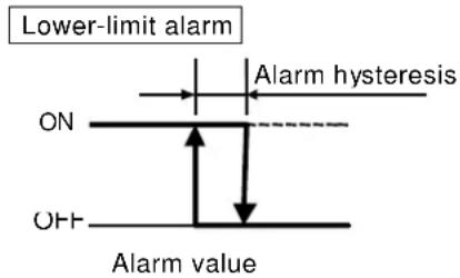
■ Standby Sequence
- The standby sequence can be used so that an alarm will not be output until the process value leaves the alarm range once and then enters it again. - For example, with a lower limit alarm, the process value will normally be below the set point, i.e., within the alarm range, when the power supply is turned ON, causing an alarm to be output. If the lower limit alarm with a standby sequence is selected, an alarm will not be output until the process value increases above the alarm set value, i.e., until it leaves the alarm range, and then falls back below the alarm set value.
■ Alarm Latch
- The alarm latch can be used to keep the alarm output ON regardless of the temperature once the alarm output has turned ON until either the power is turned OFF or the alarm latch is cleared. - The alarm latch can be cleared by either turning OFF the power or performing the alarm latch clear operation. - To clear the alarm latch during operation, press the ⚠ and ⚡ Keys for at least 2 s while the alarm 1/2 latch status is displayed in the operation level. When the latch is cleared, the latch status will be automatically changed to 0 (latch cleared). The alarm latch status is displayed separately for alarm 1 and alarm 2, enabling the latch to be cleared separately for alarm 1 and alarm 2.
- Alarm Latch Clear Operation

■ Close in Alarm/Open in Alarm
- When “close in alarm” is set, the status of the alarm function will be output as is. When “open in alarm” is set, the status of the alarm function will be reversed before being output.
- Close in alarm/open in alarm can be set separately for each alarm.
- Close in alarm/open in alarm are set in the "alarm 1 open in alarm" parameter (initial setting level (4)), and in the "alarm 2 open in alarm" parameter (initial setting level (5)).
• The default is 0 (close in alarm).
| Alarm function | Alarm output function | Alarm indicator | |
| alarm | ON | ON | Lit |
| OFF | OFF | Not | |
| alarm | ON | OFF | Lit |
| OFF | ON | Not |
Close in
lit
Open in
lit
- The alarm outputs will turn OFF (i.e., the relay contacts will open) when power is interrupted and for about two seconds after the power is turned ON regardless of the close in alarm/open in alarm setting.
• Summary of Alarm Operation
The following figure summarizes the operation of alarms when the alarm type is set to “lower-limit alarm with standby sequence” and “close in alarm” is set.
Alarm type: Lower-limit alarm with standby sequence
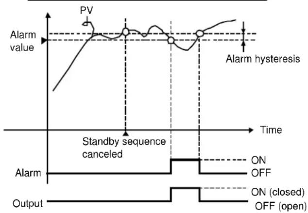
line
| Time | Alarm value | Annotation | |------|-------------|--------------------------------| | Start | Low | - | | Peak | High | PV (PV Signal) | | End | Medium | Standby sequence canceled | | End | High | Alarm hysteresis (labeled) | | End | Low | Output (Output Signal) | | End | High | ON (closed) | | End | High | OFF (Open) |4.4 Setting the SP Upper and Lower Limit Values
■ Set Point Limiter
The setting range of the set point is limited by the set point limiter. The set point limiter is used to prevent the control target from reaching abnormal temperatures.
The upper- and lower-limit values of the set point limiter are set using the "set point upper limit" and "set point lower limit" parameters in the initial setting level (3). When the set point limiter is reset, however, the set point is forcibly changed to the upper- or lower-limit value of the set point limiter if the set point is out of the limiter range as a result of resetting.
Also, when the input type and temperature unit are changed, the set point limiter is forcibly reset to the sensor setting range.

flowchart
graph TD
    A["Sensor range"] --> B["Set point limiter"]
    B --> C["Setting range"]
    C --> D["Limiter upper-limit changed"]
    D --> E["Input type changed"]
    E --> F["Upper-limit value changed"]
    F --> G["Set value"]
    G --> H["Set value"]
    H --> I["Can be set."]
    I --> J["Sensor upper-/lower-limit values"]
    J --> K["Limiter"]
    K --> L["Upper-limit"]
    L --> M["Set point"]
    M --> N["Upper-limit value changed"]
    N --> O["Set value"]
    O --> P["Can be set."]
    P --> Q["Sensor upper-/lower-limit values"]
    Q --> R["Limiter"]
    R --> S["Upper-limit"]
    S --> T["Set point"]
    T --> U["Upper-limit value changed"]
    U --> V["Set value"]
    V --> W["Can be set."]
    W --> X["Sensor upper-/lower-limit values"]
    X --> Y["Limiter"]
    Y --> Z["Upper-limit"]
    Z --> AA["Set point"]
    AA --> AB["Upper-limit value changed"]
    AB --> AC["Set value"]
    AC --> AD["Can be set."]
    AD --> AE["Sensor upper-/lower-limit values"]
    AE --> AF["Limiter"]
    AF --> AG["Upper-limit"]
    AG --> AH["Set point"]
    AH --> AI["Upper-limit value changed"]
    AI --> AJ["Set value"]
    AJ --> AK["Can be set."]
    AK --> AL["Sensor upper-/lower-limit values"]
    AL --> AM["Limiter"]
    AM --> AN["Upper-limit"]
    AN --> AO["Set point"]
    AO --> AP["Upper-limit value changed"]
    AP --> AQ["Set value"]
    AQ --> AR["Can be set."]
    AR --> AS["Sensor upper-/lower-limit values"]
    AS --> AT["Limiter"]
    AT --> AU["Upper-limit"]
    AU --> AV["Set point"]
    AV --> AW["Upper-limit value changed"]
    AW --> AX["Set value"]
    AX --> AY["Can be set."]
■ Setting
Set the set point upper and lower limits in the "set point upper limit" and "set point lower limit" parameters in the initial setting level (3). In this example, it is assumed that the input type is set to a K thermocouple with a temperature range of -99 to 1300^ .

- Setting the Set Point Upper-limit Value
Operating Procedure
• Set Point Upper Limit = 1000

flowchart
graph TD
    A["Initial setting level (3)"] --> B["SPALM ALM 1 2"]
    B --> C["SPALM ALM 2"]
    C --> D["400 OUT"]
    D --> E["SPALM ALM 1 2"]
    E --> F["1000 OUT"]
    style A fill:#f9f,stroke:#333
    style B fill:#ccf,stroke:#333
    style C fill:#cfc,stroke:#333
    style D fill:#fcc,stroke:#333
    style E fill:#cff,stroke:#333
    style F fill:#ffc,stroke:#333
- Press the ☐ Key from the initial setting level (3) and select "set point upper limit" (SP mode).
- Use the ▲ and ▼ Keys to set 1000.
- Setting the Set Point Lower-limit Value
Operating Procedure
Set Point Lower Limit = 0
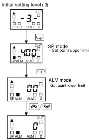
flowchart
graph TD
    A["Initial setting level (3)"] --> B["SP ALM 2"]
    B --> C["400 OUT"]
    C --> D["ALM mode"]
    D --> E["SET point lower limit"]
    E --> F["OUT"]
    style A fill:#f9f,stroke:#333
    style B fill:#ccf,stroke:#333
    style C fill:#cfc,stroke:#333
    style D fill:#fcc,stroke:#333
    style E fill:#cff,stroke:#333
    style F fill:#ffc,stroke:#333
- Press the ☐ Key from the initial setting level (3) and select "set point lower limit" (ALM mode).
- Use the ⬆ and ⬇ Keys to set 0.
4.5 Alarm Delays
■ Alarm Delays
- Delays can be set for the alarm outputs. ON and OFF delays can be set separately for alarms 1 and 2. The ON and OFF delays for alarms 1 and 2 also apply to the individual ALM1 and ALM2 indicators. The alarm ON delays will also function when the power is turned ON.
• Operation of Alarm ON and OFF Delays (for an Upper-limit Alarm)

flowchart
graph TD
    A["Alarm setting"] --> B["On delay set time"]
    B --> C["ON delay set time"]
    C --> D["OFF delay set time"]
    D --> E["Alarm latch = OFF"]
    E --> F["Alarm will not turn ON."]
    G["Alarm hysteresis"] --> H["On delay set time"]
    H --> I["ON delay set time"]
    I --> J["OFF delay set time"]
    J --> K["Alarm latch = OFF"]
- The alarm will not turn ON if the time that the alarm is ON is equal to or less than the ON delay set time. Also, the alarm will not turn OFF if the time that the alarm is OFF is equal to or less than the OFF delay set time.
- If an alarm turns OFF and then back ON during the ON delay time, the time will be remeasured from the last time the alarm turns ON. Also, if an alarm turns ON and then back OFF during the OFF delay time, the time will be remeasured from the last time the alarm turns OFF.
- Parameters Related to Alarm Delays
| Parameter name | Setting | Set (monitor) values |
| Alarm 1 ON Delay | Initial setting level (4)SP mode | 0 to 999 (s) |
| Alarm 2 ON Delay | Initial setting level (5)SP mode | 0 to 999 (s) |
| Alarm 1 OFF Delay | Initial setting level (4)ALM mode | 0 to 999 (s) |
| Alarm 2 OFF Delay | Initial setting level (5)ALM mode | 0 to 999 (s) |
* The defaults are 0, i.e., the ON and OFF delays are disabled.
Operating Procedure
Use the following procedure to set ON and OFF delays for the alarm 1 function.
An ON delay of 5 s and an OFF delay of 10 s will be set.

flowchart
graph TD
    A["Initial setting level (4)"] --> B["SP mode - Alarm 1 ON delay"]
    B --> C["ALM mode - Alarm 1 OFF delay"]
    C --> D["SP ALM ALM 1 2"]
    D --> E["OUT"]
    E --> F["SP ALM ALM 1 2"]
    F --> G["OUT"]
    G --> H["SP ALM ALM 1 2"]
    H --> I["OUT"]
    I --> J["SP ALM ALM 1 2"]
    J --> K["OUT"]
    K --> L["SP ALM ALM 1 2"]
- Select the initial setting level (4).
- Select the "alarm 1 ON delay" (SP mode) parameter by pressing the ☑ key.
- Press the ⏻ and ⏽ Keys to set the parameter to 5.
- Press the ☐ key to select the "alarm 1 OFF delay" (ALM mode) parameter.
- Press the ▲ and ▼ Keys to set the parameter to 10.
Section 5 Parameters
5.1 Conventions Used in this Section.... 5-2
- Meanings of Icons Used in this Section.... 5-2
- About Related Parameter Displays 5-2
- The Order in Which Parameters Are Described in This Section 5-2
5.2 Operation Level 5-3
5.3 Moving to the Initial Setting Level 5-8
5.4 Initial Setting Level (1) 5-9
5.5 Initial Setting Level (2) 5-14
5.6 Initial Setting Level (3) 5-16
5.7 Initial Setting Level (4) 5-20
5.8 Initial Setting Level (5) 5-24
5.1 Conventions Used in this Section
• Meanings of Icons Used in this Section

Describes the functions of the parameter.

Describes the setting range and default of the parameter.
- About Related Parameter Displays
Parameters are displayed only when the conditions of use indicated for the parameter are satisfied.
IS mode (1)
Control output assignment

Mode
Parameter name
Displayed symbol
- The Order in Which Parameters Are Described in This Section
Parameters are described level by level.
The first page of each level describes the parameters in the level and the procedure to switch between parameters.
5.2 Operation Level
Display this level to perform standard control operations. The set points and alarm values are set in this level.
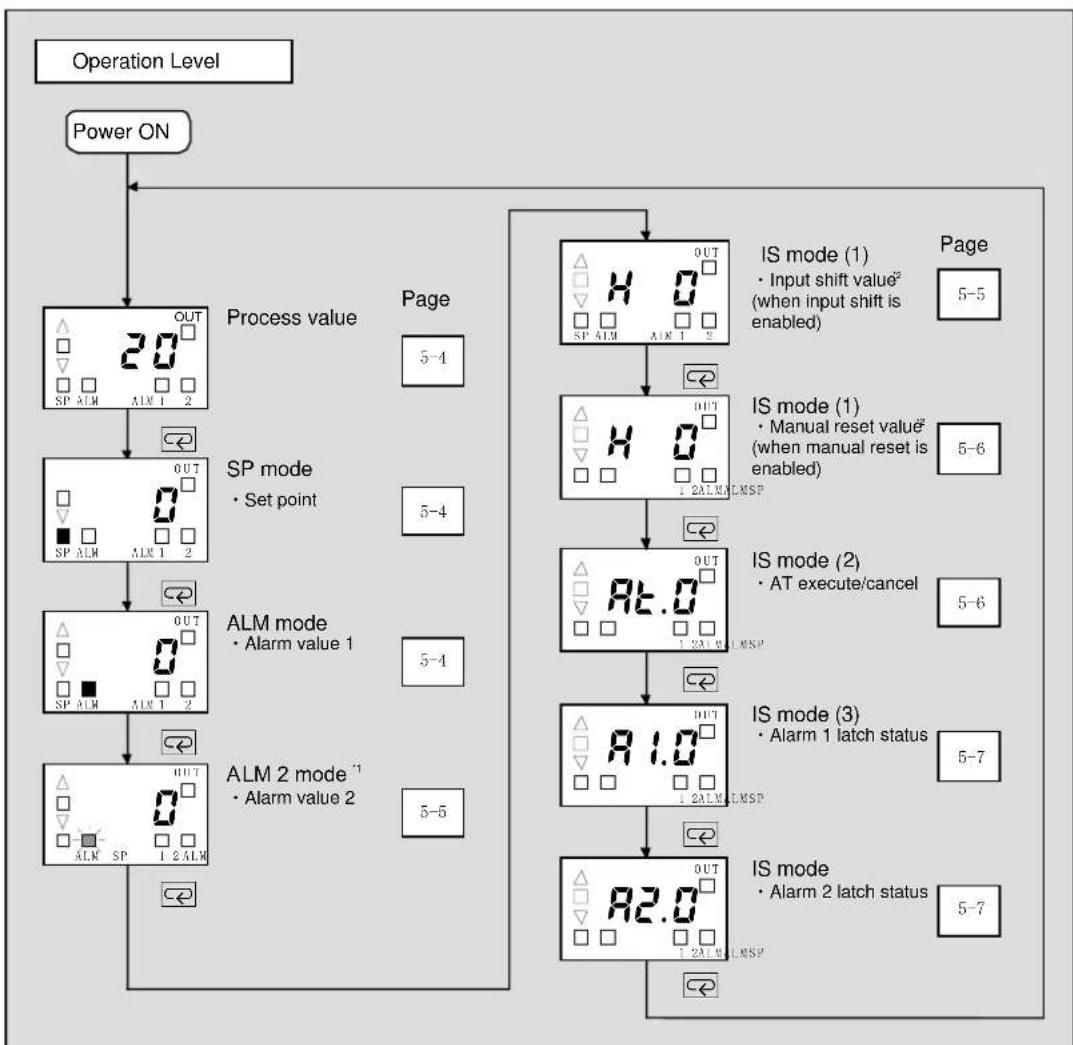
flowchart
graph TD
    A["Operation Level"] --> B["Power ON"]
    B --> C["Process value"]
    C --> D["SP mode"]
    D --> E["Set point"]
    E --> F["ALM mode"]
    F --> G["Alarm value 1"]
    F --> H["Alarm value 2"]
    C --> I["Page"]
    I --> J["IS mode (1)"]
    J --> K["Input shift value² (when input shift is enabled)"]
    K --> L["Page"]
    L --> M["5-5"]
    C --> N["5-4"]
    N --> O["AS"]
    O --> P["Manual reset value² (when manual reset is enabled)"]
    P --> Q["5-6"]
    C --> R["5-4"]
    R --> S["AS"]
    S --> T["AT execute/cancel"]
    T --> U["5-6"]
    C --> V["5-4"]
    V --> W["AS"]
    W --> X["3"]
    X --> Y["Alarm 1 latch status"]
    Y --> Z["5-7"]
    C --> AA["5-5"]
    AA --> AB["AS"]
    AB --> AC["Alarm 2 latch status"]
    AC --> AD["5-7"]
*1. When ALM2 mode is selected, the ALM mode indicator will flash.
*2. Only the input shift value or the manual reset value will be displayed. The manual reset value will be displayed if the integral time is 0 and a manual reset is enabled. The input shift is disabled while the manual reset value is being displayed.
Process value

• Displays the process value (except when no PV display is selected)
| Monitor range | Unit | |
| Process value | Input indication range(See pages A-12 and A-13.) | EU |
* The decimal position is set automatically by the selected Sensor.
SP mode Set point

- Displays the set point.

| Setting range Unit Default | |||
| Set point | SP lower limit to SP upper limit EU 0 | ||
* The decimal position is set automatically by the selected Sensor.
ALM mode Alarm value 1
This parameter is set to the input values "X" or "Y" in the alarm type list.

- This parameter sets the alarm value for alarm output 1.
| Alarm type | Setting range Unit Default | ||
| 1 to 7 | 0 to temperature range full scale | EU | 0 |
| 8 Input setting range lower-limit value to temperature range upper-limit value | EU | 0 | |
* The decimal position is set automatically by the selected Sensor.
ALM2 mode Alarm value 2
This parameter is set to the input values "X" or "Y" in the alarm type list.
The ALM will flash in the display while the alarm value 2 is displayed.


Setting
- This parameter sets the alarm value for alarm output 2.
| Alarm type | Setting range Unit Default | ||
| 1 to 7 0 | to input setting range full scale EU 0 | ||
| 8 Input | setting range lower-limit value to input setting range upper-limit value | EU | 0 |
* The decimal position is set automatically by the selected Sensor.
IS mode (1) Input shift value
H/L

- Sometimes an error occurs between the set point and the actual temperature. To offset this, a compensated value can be obtained by adding an input shift value to the input. The compensated value is displayed as the measurement value and used for control. (This applies when input shift is enabled.)
- This parameter is displayed only when control mode switch 4 is ON. Even when the switch is OFF, the input shift function remains enabled.
- The entire input range is shifted by a fixed rate. If the input shift value is set to -1^ , control will be performed for a value 1^ lower than the measured temperature.

Setting
| Setting range Unit Default | ||
| L99 to H99 (-99 to 99) | EU | H0 |
* The set value H is a positive value, and L is a negative value.
* The decimal position is set automatically by the selected Sensor.
IS mode (1) Manual reset value
H/L

- This function resets the offset that occurs when P (or PD) control is used. The offset that occurs is set in °C or °F as the manual reset value. (This applies when manual reset is enabled.)
- This parameter is displayed only when control mode switch 4 is ON. Even when the switch is OFF, the manual reset function remains enabled.

| Setting range Unit Default | ||
| L99 to H99 (-99 to 99) | EU | H0 |
* The set value H is a positive value, and L is a negative value.
* The decimal position is set automatically by the selected Sensor.
IS mode (2) AT execute/cancel
85
This parameter is used to start AT (auto-tuning). (This parameter is displayed only when no PV display is set for the PV/SP display.)
When the PV display is enabled, AT is executed when the ⏻ and ⏻ Keys are pressed simultaneously for at least 2 s while the PV is displayed.

- The MV is forcibly increased and decreased around the set point to find the characteristics of the control target. From the results, the PID constants are automatically set in the “proportional band” (P), “integral time” (I), and “derivative time” (D) parameters.

| Setting range Default | |
| 0: AT cancel1: AT execute | 0 |
IS mode (3) Alarm 1 latch status
81

• This parameter displays the alarm 1 latch status.
- The latch can be cleared by pressing the 🔒 and ⬆ Keys for at least 2 s while the alarm 1 latch status is displayed.
- The alarm 1 latch status is only displayed when latch ON (1) is set in the "alarm 1 latch" parameter in the initial setting level (4).

Monitor range
0: Latch OFF
1: Latch ON
IS mode (4) Alarm 2 latch status
82

• This parameter displays the alarm 2 latch status.
- The latch can be cleared by pressing the ⚠ and ⚡ Keys for at least 2 s while the alarm 2 latch status is displayed.
- The alarm 2 latch status is only displayed when latch ON (1) is set in the “alarm 2 latch” parameter in the initial setting level (5).

Monitor range
0: Latch OFF
1: Latch ON
5.3 Moving to the Initial Setting Level
The initial setting level is used to make the settings that maximize Temperature Controller performance. Control stops when moving to the initial setting level. The methods for moving to the initial setting level are described here.

flowchart
graph TD
    A["Initial setting level"] --> B["Power ON"]
    B --> C["Initial setting level selection display (If no key input is entered within 5 s, a software reset is executed and the display moves to the operation level)"]
    C --> D["Operation level"]
    D --> E["Press the ▲ and ▼ Keys to select the initial setting level."]
    E --> F["Press the ▲ Key for at least 3 s."]
    F --> G["Press the ▲ Key and move to the applicable initial setting level display."]
    G --> H["Output: SP ALM 1 2, OUT, -2-"]
    H --> I["Output: SP ALM 1 2, OUT, -3-"]
    I --> J["Output: SP ALM 1 2, OUT, -4-"]
    J --> K["Output: SP ALM 1 2, OUT, -5-"]
    K --> L["Output: SP ALM 1 2, OUT, -5-"]
    style A fill:#f9f,stroke:#333
    style D fill:#ccf,stroke:#333
5.4 Initial Setting Level (1)
Move to initial setting level (1) by selecting "1" in the initial setting level selection display and pressing the Key. This level is used to set the following parameters including tuning, hysteresis for ON/OFF control. In the initial setting level (1), the ▲▼ deviation indicators are lit.
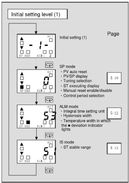
flowchart
graph TD
    A["Initial setting level (1)"] --> B["Initial setting (1)"]
    B --> C["SP mode"]
    C --> D["SP auto reset"]
    C --> E["SP/SP display"]
    C --> F["Tuning selection"]
    C --> G["ST executing display"]
    C --> H["Manual reset enable/disable"]
    C --> I["Control period selection"]
    B --> J["ALM mode"]
    J --> K["Integral time setting unit"]
    J --> L["Hysterosis width"]
    J --> M["Temperature width in which the ■ deviation indicator lights"]
    B --> N["IS mode"]
    N --> O["ST stable range"]
SP mode
PV auto reset
PV/SP display
Tuning selection
ST executing display
Manual reset enable/disable
Control period selection
- Set whether to enable or disable PV auto reset.
• Set the PV/SP display. - Select the tuning method.
- Set whether to enable or disable the ST execution display.
- Set whether to enable or disable manual reset.
• Select the control period (2/20 s or 6/60 s).

- The PV auto reset function automatically switches the display to the PV display when no key operation is performed for 16 s while in the operation level. If the "PV/SP display" parameter is set to no PV display, however, the display will switch to the SP display.
- Select either the display order for the PV and SP in the operation level or no PV display in the "PV/SP display" parameter.
- In the tuning selection, select the tuning method used for PID. When the PID settings have been changed manually, AT (AT enabled only) will be selected automatically. When the tuning method setting is changed, the PID settings will return to the default values.
- Select whether to enable or disable the flashing deviation indicators that indicate ST is in progress during ST execution.
- Select whether to enable or disable manual reset when using P or PD control in the “manual reset enable/disable” parameter. When the integral time (I) is set to 0 and a manual reset is enabled, the input shift value setting in the operation level will be used to set the manual reset value.
- When 2/20 is selected for the control period selection, the control period is 2 s when control mode switch 2 is ON, and 20 s when this switch is OFF. When 6/60 is selected for the control period selection, the control period is 6 s when control mode switch 2 is ON, and 60 s when this switch is OFF.

Setting
| Displayed number | 100's digit | 10's digit | 1's digit | |||
| PV auto reset | PV/SP display | Tuning selection | ST execution display | Manual reset enable/ disable | Control period selection | |
| 0 | Disabled | PV→SP | ST/AT | Enabled | Disabled | 2/20 |
| 1 | Enabled | ST | 6/60 | |||
| 2 | AT 2/20 | Enabled | ||||
| 3 | SP→PV | ST/AT | 6/60 | |||
| 4 | ST | Disabled | Disabled | 2/20 | ||
| 5 | AT | 6/60 | ||||
| 6 | No PV display | ST/AT | Enabled | 2/20 | ||
| 7 ST | 6/60 | |||||
| 8 | AT 2/20 | Enabled | Disabled | |||
| 9 | PV→SP | ST/AT | 6/60 | |||
| ALM mode | Integral time setting unitHysteresis widthTemperature width in which the ■ deviation indicator lights |
• Select the integral time setting unit.
• Set the hysteresis width.
- Set the temperature width in which the ■ deviation indicator lights.

- Set the integral time setting unit either to seconds or minutes in the initial setting level (2).
- The hysteresis width enables stable operation at the ON/OFF switching point for ON/OFF control. The default setting is 0.1% FS for multi-input (thermocouple/platinum resistance thermometer) models, and 0.2% FS for other input types.
- The default setting for the temperature width in which the ■ deviation indicator lights is ±0.25% FS for multi-input (thermocouple/platinum resistance thermometer) models, and ±1% FS for other input types.

| Displayed number | 100's digit 1 | 0's digit 1's digit | |
| Integral time setting unit | Hysteresis width (ON/OFF control) | Temperature width in which ■ deviation indicator lights | |
| O Second 0% FS 0% FS | |||
| 1 Minute 0.05% FS ±0.1% FS | |||
| 2 0.1% | FS ±0.25% FS | ||
| 3 0.2% | FS ±0.5% FS | ||
| 4 0.3% | FS ±0.75% FS | ||
| 5 0.5% | FS ±1% FS | ||
| 6 | 0.75% FS | ±1.25% FS | |
| 7 | 1% FS ±1.5% | FS | |
| 8 1.5% | FS ±1.75% FS | ||
| 9 | 2% FS | ±2% FS | |
IS mode ST stable range

- The setting of this parameter determines when ST operates.

| Setting range Unit Default | ||
| 1 to 999 | °C/°F | 15 |
5.5 Initial Setting Level (2)
Move to initial setting level (2) by selecting "2" in the initial setting level selection display and pressing the ☐ Key.
Manual PID settings can be set in this level.
In the initial setting level (2), the ▲■▼ deviation indicators are lit.

flowchart
graph TD
    A["Initial setting level (2)"] --> B["Initial setting (2)"]
    B --> C["SP mode<br>• Proportional band"]
    C --> D["ALM mode<br>• Integral time"]
    D --> E["IS mode<br>• Derivative time"]
    E --> F["Final setting"]
SP mode Proportional band
The proportional band (P) is set in this parameter. The proportional band for AT (auto-tuning) and ST (self-tuning) can also be set automatically.

• P operation: Refers to control in which the MV is proportional to the deviation.

| Setting range Unit Default | ||
| 1 to 999 | °C/°F | 8 |
* When the proportional band is changed manually, the tuning selection parameter automatically changes to AT (ST disabled).
ALM mode Integral time
The integral time (I) is set in this parameter. The integral time for AT (auto-tuning) and ST (self-tuning) can also be set automatically.

- I operation: Refers to a control action that is proportional to the time integral of the deviation. With proportional control, there is normally an offset (control error). Proportional action is thus used in combination with integral action. As time passes, this control error disappears, and the control temperature (process value) comes to agree with the set point.

| Setting range Unit Default | ||
| 0 to 1999 Second 233 | ||
| 0 to 99 Minute 4 | ||
* When the integral time is changed manually, the tuning selection parameter automatically changes to AT (ST disabled).
IS mode Derivative time
The derivative time (D) is set in this parameter. The derivative time for AT (auto-tuning) and ST (self-tuning) can also be set automatically.

- D operation: Refers to a control action that is proportional to the time derivative of the control error. The proportional control and integral control correct for errors in the control result, and thus the control system is late in responding to sudden changes in temperature. The derivative action increases the MV in proportion to the slope of the change in the temperature as a corrective action.
| Setting range Unit Default | |
| 0 to 1999 Second 40 |
* When the derivative time is changed manually, the tuning selection parameter automatically changes to AT (ST disabled).
5.6 Initial Setting Level (3)
Move to initial setting level (3) by selecting "3" in the initial setting level selection display and pressing the ☑ Key.
The set point upper-/lower-limit values and output assignment can be set in this level. In the initial setting level (3), the ▲ deviation indicator is lit.
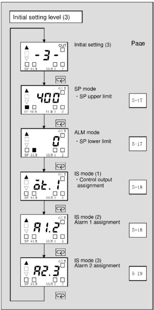
flowchart
graph TD
    A["Initial setting level (3)"] --> B["Initial setting (3)"]
    B --> C["SP mode"]
    C --> D["SP upper limit"]
    C --> E["ALM mode"]
    E --> F["SP lower limit"]
    E --> G["IS mode (1)"]
    G --> H["Control output assignment"]
    G --> I["IS mode (2)"]
    I --> J["Alarm 1 assignment"]
    I --> K["IS mode (3)"]
    K --> L["Alarm 2 assignment"]
SP mode SP upper limit

- This parameter sets the upper limit of the set point. The set point can be set within the range with the upper limit set in the "SP upper limit" parameter. If this parameter is reset, however, any set point that is outside of the new range will be forcibly changed to the SP upper limit.
- When the input type and temperature unit have been changed, the set point upper limit is forcibly changed to the upper limits of the Sensor.
• The decimal point position depends on the selected Sensor.

| Input type Setting | range Unit Default | ||
| Thermocouple | SP lower limit +1 to Input range upper limit | EU | 400 |
| Platinum resistance thermometer | 99.9 | ||
| Thermistor | 100 | ||
| Multi-input (thermocouple/platinum resistance thermometer) models | 1300 |
ALM mode SP lower limit

- This parameter sets the lower limit of the set point. The set point can be set within the range with the lower limit set in the "SP lower limit" parameter. If this parameter is reset, however, any set point that is outside of the new range will be forcibly changed to the SP lower limit.
- When the input type and temperature unit have been changed, the set point lower limit is forcibly changed to the lower limits of the Sensor.
• The decimal point position depends on the selected Sensor.

| Input type Setting range Unit Default | |||
| Thermocouple | Input range lower limit to SP upper limit -1 | EU | 0 |
| Platinum resistance thermometer | 0.0 | ||
| Thermistor | 0 | ||
| Multi-input (thermocouple/platinum resistance thermometer) models | -99 | ||
IS mode (1)
Control output assignment


- This parameter sets the function to be assigned to the control output.
| Displayed number | Set value Setting range Default | |
| 0 | No assignment | |
| 1 | Control function | 0 to 3 1: Control function |
| 2 Alarm 1 function | ||
| 3 Alarm 2 function | ||
IS mode (2)
Alarm 1 assignment


- This parameter sets the function to be assigned to alarm output 1.

| Displayed number | Set value Setting range Default | |
| 0 | No assignment | |
| 1 | Control function | 0 to 3 2: Alarm 1 function |
| 2 Alarm 1 function | ||
| 3 Alarm 2 function | ||
* Not displayed for models without alarm outputs.
IS mode (3) Alarm 2 assignment


- This parameter sets the function to be assigned to alarm output 2.

| Displayed number | Set value Setting range Default | ||
| 0 | No assignment function | 0 to 3 3: Alarm 2 function | |
| 1 | Control function | ||
| 2 Alarm 1 function | |||
| 3 Alarm 2 function | |||
* Not displayed for models without alarm output 2.
5.7 Initial Setting Level (4)
Move to initial setting level (4) by selecting "4" in the initial setting level selection display and pressing the ☑ Key.
The settings related to the alarm 1 ON/OFF delay and alarm 1 can be set in this level. In the initial setting level (4), the ▲■ deviation indicators are lit.
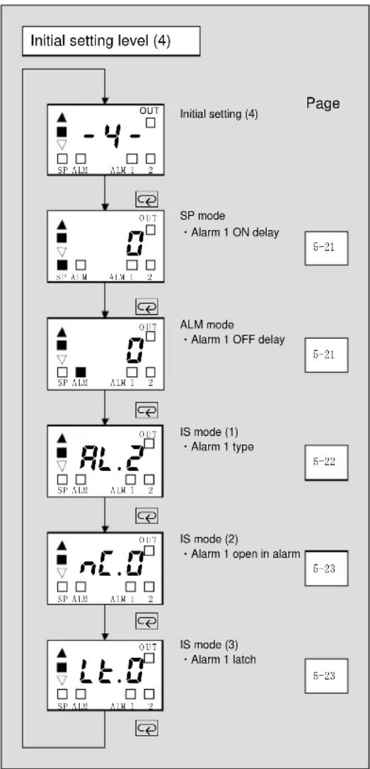
flowchart
graph TD
    A["Initial setting level (4)"] --> B["Initial setting (4)"]
    B --> C["SP ALM ALM 1 2"]
    C --> D["SP ALM ALM 1 2"]
    D --> E["SP ALM ALM 1 2"]
    E --> F["SP ALM ALM 1 2"]
    F --> G["SP ALM ALM 1 2"]
    G --> H["SP ALM ALM 1 2"]
    H --> I["SP ALM ALM 1 2"]
    I --> J["SP ALM ALM 1 2"]
    J --> K["SP ALM ALM 1 2"]
    K --> L["SP ALM ALM 1 2"]
    L --> M["SP ALM ALM 1 2"]
    M --> N["SP ALM ALM 1 2"]
    N --> O["SP ALM ALM 1 2"]
    O --> P["SP ALM ALM 1 2"]
    P --> Q["SP ALM ALM 1 2"]
    Q --> R["SP ALM ALM 1 2"]
    R --> S["SP ALM ALM 1 2"]
    S --> T["SP ALM ALM 1 2"]
    T --> U["SP ALM ALM 1 2"]
    U --> V["SP ALM ALM 1 2"]
    V --> W["SP ALM ALM 1 2"]
    W --> X["SP ALM ALM 1 2"]
    X --> Y["SP ALM ALM 1 2"]
    Y --> Z["SP ALM ALM 1 2"]
    Z --> AA["SP ALM ALM 1 2"]
    AA --> AB["SP ALM ALM 1 2"]
    AB --> AC["SP ALM ALM 1 2"]
    AC --> AD["SP ALM ALM 1 2"]
    AD --> AE["SP ALM ALM 1 2"]
    AE --> AF["SP ALM ALM 1 2"]
    AF --> AG["SP ALM ALM 1 2"]
    AG --> AH["SP ALM ALM 1 2"]
    AH --> AI["SP ALM ALM 1 2"]
    AI --> AJ["SP ALM ALM 1 2"]
    AJ --> AK["SP ALM ALM 1 2"]
    AK --> AL["SP ALM ALM 1 2"]
    AL --> AM["SP ALM ALM 1 2"]
    AM --> AN["SP ALM ALM 1 2"]
    AN --> AO["SP ALM ALM 1 2"]
    AO --> AP["SP ALM ALM 1 2"]
    AP --> AQ["SP ALM ALM 1 2"]
    AQ --> AR["SP ALM ALM 1 2"]
    AR --> AS["SP ALM ALM 1 2"]
    AS --> AT["SP ALM ALM 1 2"]
    AT --> AU["SP ALM ALM 1 2"]
    AU --> AV["SP ALM ALM 1 2"]
    AV --> AW["SP ALM ALM 1 2"]
    AW --> AX["SP ALM ALM 1 2"]
    AX --> AY["SP ALM ALM 1 2"]
    AY --> AZ["SP ALM ALM 1 2"]
    AZ --> BA["SP ALM ALM 1 2"]
    BA --> BB["SP ALM ALM 1 2"]
    BB --> BC["SP ALM ALM 1 2"]
    BC --> BD["SP ALM ALM 1 2"]
    BD --> BE["SP ALM ALM 1 2"]
    BE --> BF["SP ALM ALM 1 2"]
    BF --> BG["SP ALM ALM 1 2"]
    BG --> BH["SP ALM ALM 1 2"]
    BH --> BI["SP ALM ALM 1 2"]
    BI --> BJ["SP ALM ALM 1 2"]
    BJ --> BK["SP ALM ALM 1 2"]
    BK --> BL["SP ALM ALM 1 2"]
    BL --> BM["SP ALM ALM 1 2"]
    BM --> BN["SP ALM ALM 1 2"]
    BN --> BO["SP ALM ALM 1 2"]
    BO --> BP["SP ALM ALM 1 2"]
    BP --> BQ["SP ALM ALM 1 2"]
    BQ --> BR["SP ALM ALM 1 2"]
    BR --> BS["SP ALM ALM 1 2"]
    BS --> BT["SP ALM ALM 1 2"]
    BT --> BU["SP ALM ALM 1 2"]
    BU --> BV["SP ALM ALM 1 2"]
    BV --> BW["SP ALM ALM 1 2"]
    BW --> BX["SP ALM ALM 1 2"]
    BX --> BY["SP ALM ALM 1 2"]
    BY --> BZ["SP ALM ALM 1 2"]
    BZ --> CA["SP ALM ALM 1 2"]
    CA --> CB["SP ALM ALM 1 2"]
    CB --> CC["SP ALM ALM 1 2"]
    CC --> CD["SP ALM ALM 1 2"]
    CD --> CE["SP ALM ALM 1 2"]
    CE --> CF["SP ALM ALM 1 2"]
    CF --> CG["SP ALM ALM 1 2"]
    CG --> CH["SP ALM ALM 1 2"]
    CH --> CI["SP ALM ALM 1 2"]
    CI --> CJ["SP ALM ALM 1 2"]
    CJ --> CK["SP ALM ALM 1 2"]
SP mode Alarm 1 ON delay
Alarm 1 function is prevented from turning ON until after the delay time set in this parameter has elapsed.

- Set the time for which the ON delay is to be enabled.
• To disable the ON delay, set 0.

| Parameter | Setting | range | Unit |
| Alarm 1 ON delay 0 to | 999 Second 0 |
Default
* This parameter is displayed regardless of the output assignment setting.
ALM mode Alarm 1 OFF delay
Alarm 1 function is prevented from turning OFF until after the delay time set in this parameter has elapsed.

- Set the time for which the OFF delay is to be enabled.
• To disable the OFF delay, set 0.

| Parameter | Setting | range | Unit |
| Alarm 1 OFF delay 0 to 999 Second 0 | |||
Default
* This parameter is displayed regardless of the output assignment setting.
IS mode (1) Alarm 1 type
AL

• Select one of the following nine alarm 1 types:
- This parameter is displayed only for models without alarm outputs (i.e., models without an alarm mode switch). Settings for models with alarm outputs are set using the alarm mode switch.
| Set value | Alarm type | Alarm output operation |
| 0, 9 | Alarm function OFF Output OFF | |
| 1 | Upper- and lower-limit |  |
| 2 | Upper-limit | ~ |
| 3 | Lower-limit |  |
| 4 | Upper- and lower-limit range | ~ |
| 5 | Upper- and lower-limit with standby sequence | 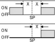 |
| 6 | Upper-limit with standby sequence | |
| 7 | Lower-limit with standby sequence |  |
| 8 | Absolute-value upper-limit |
* Alarm values 1 to 7: Set the deviation from the SP (set point) in the alarm value (X).
Alarm 8: Set the absolute value from 0^/^ in the alarm value (Y).
* The default is 2 (upper-limit alarm).
* This parameter is not displayed for models with alarm outputs. The alarm type can be set for these models using the alarm type switch.
* For models without alarm outputs, this parameter is displayed regardless of the output assignment setting.
IS mode (2) Alarm 1 open in alarm


• This parameter sets the output status for alarm 1.
- When “close in alarm” is set, the status of the alarm 1 function will be output as is. When “open in alarm” is set, the status of the alarm 1 function will be reversed before being output.
| Parameter | Setting | range |
| Alarm 1 open in alarm | 0: Closed in alarm1: Open in alarm | 0: Closed in alarm |
Default
* This parameter is displayed regardless of the output assignment setting.
* The alarm 1 indicator will display the alarm output function status as is regardless of the alarm 1 closed in alarm/open in alarm setting.
IS mode (3) Alarm 1 latch


- When this parameter is set to ON, once the alarm 1 function has turned ON it is held until the power is turned OFF or the latch is cleared.
- If the alarm 1 function is set to "close in alarm," the outputs are kept closed. If they are set to "open in alarm," they are kept open.
- When the alarm 1 latch is set to "latch ON" (1), the alarm 1 latch status will be displayed in the operation level. During operation, the latch clear operation can be performed in the alarm latch status window.

| Parameter | Setting range | Default |
| Alarm 1 latch | 0: Latch OFF1: Latch ON | 0: Latch OFF |
* This parameter is displayed regardless of the output assignment setting.
5.8 Initial Setting Level (5)
Move to initial setting level (5) by selecting "5" in the initial setting level selection display and pressing the ☑ Key.
The settings related to the alarm 2 ON/OFF delay and alarm 2 can be set in this level. In the initial setting level (5), the ▼ deviation indicator is lit.

flowchart
graph TD
    A["Initial setting level (5)"] --> B["Initial setting (5)"]
    B --> C{OUT}
    C --> D["SP ALM ALM 1 2"]
    D --> E{OUT}
    E --> F{SP ALM ALM 1 2}
    F --> G{OUT}
    G --> H{ALM mode ON delay 5-25}
    H --> I{Alarm 2 OFF delay 5-25}
    I --> J{OUT}
    J --> K{ALM mode OFF delay 5-25}
    K --> L{OUT}
    L --> M{IS mode (1) Alarm 2 type 5-26}
    M --> N{OUT}
    N --> O{IS mode (2) Alarm 2 open in alarm 5-27}
    O --> P{OUT}
    P --> Q{IS mode (3) Alarm 2 latch 5-27}
    Q --> R{OUT}
    R --> S{IS mode (3) Alarm 2 latch 5-27}
SP mode Alarm 2 ON delay
Alarm 2 function is prevented from turning ON until after the delay time set in this parameter has elapsed.

- Set the time for which the ON delay is to be enabled.
• To disable the ON delay, set 0.
| Parameter | Setting range | Unit | Default |
| Alarm 2 ON delay 0 to | 999 Second 0 |
* This parameter is displayed regardless of the output assignment setting.
ALM mode Alarm 2 OFF delay
Alarm 2 function is prevented from turning OFF until after the delay time set in this parameter has elapsed.

- Set the time for which the OFF delay is to be enabled.
• To disable the OFF delay, set 0.
| Parameter | Setting range | Unit | Default |
| Alarm 2 OFF delay 0 to | 999 Second 0 |
* This parameter is displayed regardless of the output assignment setting.
IS mode (1) Alarm 2 type
RL


- Select one of the following nine alarm 2 types:
| Set value | Alarm type | Alarm output operation |
| 0 Alarm function OFF Output OFF | ||
| 1 Upper- and lower-limit |  | |
| 2 Upper-limit | 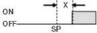 | |
| 3 Lower-limit |  | |
| 4 Upper- and lower-limit range |  | |
| 5 Upper- and lower-limit with standby sequence | 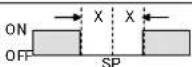 | |
| 6 Upper-limit with standby sequence | 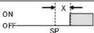 | |
| 7 Lower-limit with standby sequence |  | |
| 8 Absolute-value upper-limit |  | |
* Alarm values 1 to 7: Set the deviation from the SP (set point) in the alarm value (X).
Alarm 8: Set the absolute value from 0^/^ in the alarm value (Y).
* The default is 2 (upper-limit alarm).
* This parameter is displayed regardless of the output assignment setting.
IS mode (2) Alarm 2 open in alarm


• This parameter sets the output status for alarm 2.
- When “close in alarm” is set, the status of the alarm 2 function will be output as is. When “open in alarm” is set, the status of the alarm 2 function will be reversed before being output.

| Parameter | Setting range | Default |
| Alarm 2 open in alarm | 0: Closed in alarm1: Open in alarm | 0: Closed in alarm |
* This parameter is displayed regardless of the output assignment setting.
* The alarm 2 indicator will display the alarm output function status as is regardless of the alarm 2 closed in alarm/open in alarm setting.
IS mode (3) Alarm 2 latch


- When this parameter is set to ON, once the alarm 2 function has turned ON it is held until the power is turned OFF or the latch is cleared.
- If the alarm 2 function is set to "close in alarm," the outputs are kept closed. If they are set to "open in alarm," they are kept open.
- When the alarm 2 latch is set to "latch ON" (1), the alarm 2 latch status will be displayed in the operation level. During operation, the latch clear operation can be performed in the alarm latch status window.

| Parameter | Setting range | Default |
| Alarm 2 latch | 0: Latch OFF1: Latch ON | 0: Latch OFF |
* This parameter is displayed regardless of the output assignment setting.
Appendices
Specifications ...... A-2
■ Ratings......A-2
■ Characteristics....A-3
Error Displays....A-4
Burnout/Short-circuit Display and Causes....A-7
Parameter Operation Lists....A-8
Sensor Input Setting Range, Indication Range,
Control Range ......A-12
Setting Levels Diagram....A-14
Parameter Flow ......A-15
Specifications
■ Ratings
| Supply voltage 100 | to 240 VAC, 50/60 Hz 24 VAC, 50/60 Hz/24 VDC | ||
| Operating voltage range | 85 to 110% of rated supply voltage | ||
| Power consumption | 5 VA 3 VA/2 W | ||
| Sensor input*1 | Thermocouple input type: K, J, LPlatinum resistance thermometer input type: Pt100, JPt100Thermistor: E52-THE□□Multi-input (thermocouple/platinum resistance thermometer) type: K, J, L, T, U, N, R, Pt100, JPt100 | ||
| Control output | Relay output | E5CSV | SPST-NO, 250 VAC, 3A (resistive load) Electrical durability: 100,000 operationsMin. applicable load: 5 V, 10 mA |
| E5CS-U | SPDT, 250 VAC, 3A (resistive load)Electrical durability: 100,000 operationsMin. applicable load 5 V 10 mA | ||
| Voltage output(for driving the SSR) | 12 VDC, 21 mA | ||
| Alarm output | SPST-NO, 250 VAC, 1A (resistive load)Electrical durability: 100,000 operationsMin. applicable load: 5 V, 10 mA | ||
| Control method ON/OFF or 2-PID (with auto tuning) | |||
| Setting method Digital setting using front panel keys | |||
| Indication method 7-segment digital display (character height: 13.5 mm) and deviation indicators | |||
| Other functions | Setting change prohibit (key protection)Input shiftTemperature unit change (°C/°F)Direct/reverse operationTemperature range, Sensor switching*2(K/J/L, Pt100/JPt100)Control period switching9-mode alarm outputSensor error detection (except thermistor models) | ||
| Ambient temperature | -10 to 55°C (with no condensation or icing); with 3-year guarantee: -10 to 50°C | ||
| Ambient humidity 25% to 85% | |||
| Storage temperature | -25 to 65°C (with no condensation or icing) | ||
| Altitude 2,000 m or less | |||
| Recommended fuse | T2A, 250 VAC, time lag, low shut-off capacity | ||
| Installation environment | Installation Category II, Pollution Class 2 (IEC 61010-1 compliant) | ||
*1. For the setting ranges for each sensor input, see page A-12.
*2. Switching is performed between a thermocouple and platinum resistance thermometer for multi-input models (i.e., models that support both thermocouple and platinum resistance thermometer input).
■ Characteristics
| Indication accuracy(ambient temperature of 23°C) | Thermocouple: *1(±0.5% of indication value or ±1°C, whichever is greater) ±1 digit max.(E5CSV)(±1.0% of indication value or ±2°C, whichever is greater) ±1 digit max.(E5CS-U)Platinum resistance thermometer: *2(±0.5% of indication value or ±1°C, whichever is greater) ±1 digit max.Thermistor:(0.5% FS of indication value) ±1 digit max. (E5CSV)(1.0% FS of indication value) ±1 digit max. (E5CS-U) | ||
| Hysteresis(for ON/OFF control) | 0.2% FS(0.1% FS for multi-input (thermocouple/platinum resistance thermometer) models) | ||
| Proportional band (P) | 1 to 999°C (automatic adjustment using auto-tuning/self-tuning) | ||
| Integral time (I) 0 to 1,999 s (automatic adjustment using auto-tuning/self-tuning) | |||
| Derivative time (D) 0 to 1,999 s (automatic adjustment using auto-tuning/self-tuning) | |||
| Control period 2/20 s (6/60 s) | |||
| Sampling period 500 ms | |||
| Insulation resistance 20 MΩ min. (at 500 VDC) | |||
| Dielectric strength | 2,000 VAC, 50/60 Hz for 1 min between current-carrying terminals of different polarity | ||
| Malfunction vibration 10 to 55 Hz, 20 m/s2for 10 min each in X, Y and Z directions | |||
| Vibration resistance | 10 to 55 Hz, single amplitude of 0.75 mm for 2 hr each in X, Y, and Z directions | ||
| Malfunction shock 100 m/s2, 3 times each in six directions | |||
| Shock resistance 300m/s2, 3 times each in six directions | |||
| Weight | E5CSV | Approx. 120 g | Adapter: Approx. 10 g |
| E5CS-U | Approx. 110 g | ||
| Protective structure | E5CSV Front panel: Equivalent to IP66; Rear case: IP20; Terminals: IP00 | ||
| E5CS-U | Front panel: Equivalent to IP50; Rear case: IP20; Terminals: IP00 | ||
| Memory protection EEPROM (non-volatile memory) (number of writes: 1,000,000) | |||
*1. The following exceptions apply to thermocouples.
• U, L: ±2°C ±1 digit max.
• R: ±3°C ±1 digit max. at 200°C or less
*2. The following exceptions apply to platinum resistance thermometers.
- Input set values 0, 1, 2, 3 for E5CSV: 0.5% FS ± 1 digit max.
• Input set value 1 for E5CS-U: 0.5% FS ±1 digit max.
*3. The following exceptions apply to thermistors.
- The specified accuracy may not be maintained if the ^ C unit setting is used and the temperature indication range exceeds the set temperature range ± 10% FS.
- The specified accuracy may not be maintained for a temperature range of 609 to 630^ (input setting number 4 or 9) if the ^ unit setting is used and the temperature indication range exceeds the set temperature range -5% to 10% FS.
Error Displays
When an error occurs, the error contents are shown on the display window.
This section describes how to check error codes on the display, and the actions to be taken to remedy the problems.
| FFF | Overflow |
| Meaning | (1) The process value is higher than the control temperature range.(2) The Sensor has shorted when using a thermistor model. |
| Action | Check the wiring of inputs for miswiring, disconnections, and short-circuits and check the input type.If no abnormality is found in the wiring and input type, turn the power OFF then back ON again. |
| Operation at Error | The error is displayed after it occurs, and the alarm output (models with alarm output only) indicates an abnormally high temperature. The control output turns OFF when using heating control (reverse operation), and turns ON when using cooling control (direct operation).* The error is displayed during PV display only.The error is not displayed while the set point, alarm value, or input shift value is displayed.This error is not applicable to multi-input (thermocouple/platinum resistance thermometer) models. |
| --- | Underflow |
| Meaning | (1) The process value is lower than the control temperature range.(2) A Sensor disconnection has occurred when using a thermistor model. |
| Action | Check the wiring of inputs for miswiring, disconnections, and short-circuits and check the input type.If no abnormality is found in the wiring and input type, turn the power OFF then back ON again. |
| Operation at Error | The error is displayed after it occurs, and the alarm output (models with alarm output only) indicates an abnormally low temperature. The control output turns ON when using heating control (reverse operation), and turns OFF when using cooling control (direct operation).* The error is displayed during PV display only.The error is not displayed while the set point, alarm value, or input shift value is displayed.This error is not applicable to multi-input (thermocouple/platinum resistance thermometer) models. |
| FFF | Flashing | Input Sensor Error (High Temperature) |
| Meaning | (1) The process value is higher than the overflow temperature or a sensor error has occurred when using a thermocouple input or platinum resistance thermometer input model.(2) The process value is higher than the control temperature range or a sensor error has occurred when using a multi-input (thermocouple/platinum resistance thermometer) model. | |
| Action | Check the wiring of inputs for miswiring, disconnections, and short-circuits and check the input type.If no abnormality is found in the wiring and input type, turn the power OFF then back ON again. | |
| Operation at Error | The error is displayed after it occurs, and the alarm output (models with alarm function only) indicates that the upper-limit value has been exceeded. The control outputs turn OFF.* Input sensor error detection is not provided in thermistor models. | |
| --- | Flashing | Input Sensor Error (Low Temperature) |
| Meaning | (1) The process value is lower than the underflow temperature or a sensor error has occurred when using a thermocouple input or platinum resistance thermometer input model.(2) The positive and negative connection of the Sensor is reversed when using thermocouple input.(3) The process value is lower than the control temperature range or a sensor error has occurred when using a multi-input (thermocouple/platinum resistance thermometer) model. | |
| Action | Check the wiring of inputs for miswiring, disconnections, and short-circuits and check the input type.If no abnormality is found in the wiring and input type, turn the power OFF then back ON again. | |
| Operation at Error | The error is displayed after it occurs, and the alarm output models with alarm function only) indicates that the lower-limit value has been exceeded. The control outputs turn OFF.* Input sensor error detection is not provided in thermistor models. | |
| E I I | Memory Error | |
| Meaning | An error has occurred in the internal memory. | |
| Action | Turn the power ON again. If the display remains the same, the Controller must be repaired. If the display is restored, then the probable cause is electrical noise affecting the control system. Check for electrical noise. | |
| Operation at Error | The control outputs and alarm outputs turn OFF. | |
| CCC |
| ??? |
Display Range Exceeded
- Meaning
This does not indicate an error. It is displayed if the process value exceeds the display range when the control range is larger than the display range.
- When less than -99 :ccc
- When more than 1999 :
- Operation
Control continues, allowing normal operation. This display is shown only during PV display.
Burnout/Short-circuit Display and Causes
The display window shows the error details if an input sensor burnout or short-circuit occurs. The error display and control output operation for burnouts and short-circuits is explained below for each input type.
- Thermocouple
| Status Display Control output | ||
| Burnout |  | FFF flashing OFF |
- The room temperature is displayed if an input short-circuit occurs.
- Platinum Resistance Thermometer
| Status Display Control | output | |||
| Burnout | Models with Terminal Blocks | Plug-in Models | FFF flashing OFF | |
 |  | |||
 |  | |||
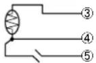 |  | --- flashing OFF | ||
| 2 or 3 wires disconnected FFR | flashing OFF | |||
| Short-circuit | 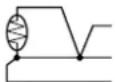 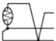 | --- flashing OFF | ||
- The resistance value for platinum resistance thermometers is 100 Ω at 0°C and 140 Ω at 100°C.
- Thermistor
| Status | Display | Control output | |
| Burnout |  | --- * | ON during heating control (reverse operation)OFF during cooling control (direct operation) |
| Short-circuit |  | FFF* | OFF during heating control (reverse operation)ON during cooling control (direct operation) |
* The display does not flash.
Parameter Operation Lists
■ Operation Level
| Parameters | Mode indicators/ displayed text | Setting (monitor) value Default Unit | Set value | ||
| Process value - | Sensor input indication range | EU | |||
| Set point SP mode | SP lower limit to SP upper limit | 0 | EU | ||
| Alarm value 1 ALM mode | 1 to 7: 0 to | input setting range full scale8: Input setting range lower-limit value to input setting range upper-limit value | 0 | EU | |
| Alarm value 2 ALM2 | mode | 1 to 7: 0 to input setting range full scale8: Input setting range lower-limit value to input setting range upper-limit value | 0 | EU | |
| Input shift value IS mode | L99 to H99 (-99 to 99) | H0 | EU | ||
| Manual reset value IS mode | L99 to H99 (-99 to 99) | H0 | EU | ||
| Rt | 0: AT cancel AT execute/cancel IS mode1: AT execute | 0 | None | ||
| R1 | 0: Latch OFF Alarm 1 latch status IS mode01: Latch ON | 0 | None | ||
| R2 | 0: Latch OFF Alarm 2 latch status IS mode01: Latch ON | 0 | None | ||
■ Initial Setting Level (1)
| Parameters | Mode indicators/ displayed text | Setting (monitor) value Default Unit | Set value | |||||
| SP mode 100's digit | 0: No PV auto reset1: Yes | 0 | None | |||||
| PV/SP display Tuning selection | SP mode 10's digit | PV/SP display | Tuning selection | 0 | None | |||
| 0 | PV-SP | ST/AT | ||||||
| 1 | ST | |||||||
| 2 | AT | |||||||
| 3 | SP-PV | ST/AT | ||||||
| 4 | ST | |||||||
| 5 | AT | |||||||
| 6 | No PV display | ST/AT | ||||||
| 7 | ST | |||||||
| 8 | AT | |||||||
| 9 | PV-SP | ST/AT | ||||||
| ST executing display Manual reset enable/disable Control period selection | SP mode 1's digit | ST executing display | Manual reset enable/ disable | Control period selection | 0 | None(s) | ||
| 0 | Enabled | Disabled | 2/20 | |||||
| 1 | 6/60 | |||||||
| 2 | Enabled | 2/20 | ||||||
| 3 | 6/60 | |||||||
| 4 | Disabled | Disabled | 2/20 | |||||
| 5 | 6/60 | |||||||
| 6 | Enabled | 2/20 | ||||||
| 7 | 6/60 | |||||||
| 8 | Enabled | Disabled | 2/20 | |||||
| 9 | 6/60 | |||||||
| Integral time setting unit | ALM mode 100's digit | 0: Second1: Minute | 0 | None | ||||
| Hysteresis width | ALM mode 10's digit | 0: 0% FS1: 0.05% FS2: 0.1% FS3: 0.2% FS4: 0.3% FS5: 0.5% FS6: 0.75% FS7: 1% FS8: 1.5% FS9: 2% FS | 3^*1 | None | ||||
| Temperature width in which the deviation indicator lights | ALM mode 1's digit | 0: 0% FS1: ±0.1% FS2: ±0.25% FS3: ±0.5% FS4: ±0.75% FS5: ±1% FS6: ±1.25% FS7: ±1.5% FS8: ±1.75% FS9: ±2% FS | 5^*2 | None | ||||
| ST stable range IS mode | 1 to 999 | 15 | °C/°F | |||||
*1. The default is 2, however, for multi-input (thermocouple/platinum resistance thermometer) models.
*2. The default is 2, however, for multi-input (thermocouple/platinum resistance thermometer) models.
■ Initial Setting Level (2)
| Parameters | Mode indicators /displayed text | Setting (monitor) value Default Unit | Set value | ||
| Proportional band | SP mode | 1 to 999 8 °C/°F | |||
| Integral time | ALM mode | 0 to 1999 233 Second0 to 99 4 Minute | |||
| Derivative time | IS mode | 0 to 1999 40 Second |
■ Initial Setting Level (3)
| Parameters | Mode indicators /displayed text | Setting (monitor) value Default Unit | Set value | |||
| SP upper limit SP mode | SP lower lim | it + 1 to Input range upper limit | Thermocouple | 400 | EU | |
| Platinum resistance thermometer | 99.9 | |||||
| Thermistor | 100 | |||||
| Multi-input (thermocouple/ platinum resistance thermometer) models | 1300 | |||||
| SP lower limit | ALM mode | Input range lower limit to SP upper limit - 1 | Thermocouple | 0 | EU | |
| Platinum resistance thermometer | 0.0 | |||||
| Thermistor | 0 | |||||
| Multi-input (thermocouple/ platinum resistance thermometer) models | -99 | |||||
| Control output assignment | IS mode t | 0: Not assigned1: Control function2: Alarm 1 function3: Alarm 2 function | 1 | None | ||
| Alarm 1 assignment | IS mode R_1 | 0: Not assigned1: Control function2: Alarm 1 function3: Alarm 2 function | 2 | None | ||
| Alarm 2 assignment | IS mode R_2 | 0: Not assigned1: Control function2: Alarm 1 function3: Alarm 2 function | 3 | None | ||
■ Initial Setting Level (4)
| Parameters | Mode indicators /displayed text | Setting (monitor) value Default Unit | Set value | ||
| Alarm 1 ON delay SP mode | 0 to 999 | 0 | Second | ||
| Alarm 1 OFF delay ALM mode | 0 to 999 | 0 | Second | ||
| Alarm 1 type IS mode | RL | 0, 9: No alarm1: Upper-/lower-limit2: Upper limit3: Lower limit4: Upper-/lower-limit range5: Upper- and lower-limit with standby sequence6: Upper-limit with standby sequence7: Lower-limit with standby sequence8: Absolute-value upper-limit | 2 | None | |
| nE | 0: Closed in alarm Alarm 1 open in alarm IS mode 01: Open in alarm | 0 | None | ||
| LT | 0: Latch OFF Alarm 1 latch IS mode 01: Latch ON | 0 | None | ||
■ Initial Setting Level (5)
| Parameters | Mode indicators /displayed text | Setting (monitor) value Default Unit | Set value | ||
| Alarm 2 ON delay SP mode | 0 to 999 | 0 | Second | ||
| Alarm 2 OFF delay ALM mode | 0 to 999 | 0 | Second | ||
| Alarm 2 type IS mode | RL | 0: No alarm1: Upper-/lower-limit2: Upper limit3: Lower limit4: Upper-/lower-limit range5: Upper- and lower-limit with standby sequence6: Upper-limit with standby sequence7: Lower-limit with standby sequence8: Absolute-value upper-limit | 2 | None | |
| nC | 0: Closed in alarm Alarm 2 open in alarm IS mode 01: Open in alarm | 0 | None | ||
| LT | 0: Latch OFF Alarm 2 latch IS mode 01: Latch ON | 0 | None | ||
Sensor Input Setting Range, Indication Range, Control Range
| Input type | Specifications | Temperature range | Input temperature range Control range | |
| Thermocouple | K | 0 | 0 to 200 (°C)/0 to 200 (°F) | -20 to 220 (°C)/ -20 to 220 (°F) |
| 1 | 0 to 300 (°C)/0 to 300 (°F) | -30 to 330 (°C)/ -30 to 330 (°F) | ||
| 2 | 0 to 400 (°C)/0 to 400 (°F) | -40 to 440 (°C)/ -40 to 440 (°F) | ||
| 3 | 0 to 500 (°C)/0 to 500 (°F) | -50 to 550 (°C)/ -50 to 550 (°F) | ||
| 4 | 0 to 600 (°C)/0 to 600 (°F) | -60 to 660 (°C)/ -60 to 660 (°F) | ||
| 5 0 to 999 ( °C)/0 to 999 (°F) | -99* to 1,098.9* (°C)/ -99* to 1,098.9* (°F) | |||
| J/L | 6 | 0 to 200 (°C)/0 to 999 (°F) | -20 to 220 (°C)/ -99* to 1,098.9* (°F) | |
| 7 | 0 to 300 (°C)/0 to 300 (°F) | -30 to 330 (°C)/ -30 to 330 (°F) | ||
| 8 | 0 to 400 (°C)/0 to 400 (°F) | -40 to 440 (°C)/ -40 to 440 (°F) | ||
| 9 0 to 500 ( °C)/0 to 500 (°F) | -50 to 550 (°C)/ -50 to 550 (°F) | |||
| Platinum resistance thermometer | Pt100/JPt1 00 | 0 | -50 to 50 (°C)/-50 to 50 (°F) | -60 to 60 (°C)/ -60 to 60 (°F) |
| 1 | 0.0 to 50.0 (°C)/0.0 to 50.0 (°F) | -5.0 to 55.0 (°C)/-5.0 to 55.0 (°F) | ||
| 2 | -20 to 80 (°C)/-20 to 80 (°F) | -30 to 90 (°C)/-30 to 90 (°F) | ||
| 3 | 0.0 to 99.9 (°C)/0.0 to 99.9 (°F) | -9.9 to 109.8 (°C)/ -9.9 to 109.8 (°F) | ||
| 4 | 0 to 200 (°C)/0 to 200 (°F) | -20 to 220 (°C)/-20 to 220 (°F) | ||
| 5 | 0 to 300 (°C)/0 to 300 (°F) | -30 to 330 (°C)/-30 to 330 (°F) | ||
| 6 | 0 to 400 (°C)/0 to 400 (°F) | -40 to 440 (°C)/-40 to 440 (°F) | ||
| 7 | 0 to 300 (°C)/0 to 600 (°F) | -30 to 330 (°C)/-60 to 660 (°F) | ||
| 8 | 0 to 400 (°C)/0 to 800 (°F) | -40 to 440 (°C)/-80 to 880 (°F) | ||
| 9 | 0.0 to 199.9 (°C)/0.0 to 199.9 (°F) | -19.9 to 219.8 (°C)/-19.9 to 219.8 (°F) | ||
| Thermistor | 6 KΩ (0°C) | 0 | -50 to 50 (°C)/ -50 to 100 (°F) | -50 to 60 (°C)/-57.5* to 115 (°F) |
| 6 KΩ (0°C) | 1 0 to 100 ( °C)/0 to 200 (°F) | -10 to 110 (°C)/-10 to 220 (°F) | ||
| 30 KΩ (0°C) | 2 | 50 to 150 (°C)/100 to 300 (°F) | 0 to 160 (°C)/35 to 320 (°F) | |
| 550 Ω (200°C) | 3 | 100 to 200 (°C)/200 to 400 (°F) | 0 to 210 (°C)/35 to 420 (°F) | |
| 4 KΩ (200°C) | 4 | 150 to 300 (°C)/300 to 600 (°F) | 25 to 315 (°C)/80 to 630 (°F) | |
| 6 KΩ (0°C) | 5 | -50 to 50 (°C)/ -50 to 100 (°F) | -50 to 60 (°C)/ -57.5* to 115 (°F) | |
| 6 KΩ (0°C) | 6 0 to 100 ( °C)/0 to 200 (°F) | -10 to 110 (°C)/ -10 to 220 (°F) | ||
| 30 KΩ (0°C) | 7 | 50 to 150 (°C)/100 to 300 (°F) | 0 to 160 (°C)/35 to 320 (°F) | |
| 550 Ω (200°C) | 8 | 100 to 200 (°C)/200 to 400 (°F) | 0 to 210 (°C)/35 to 420 (°F) | |
| 4 KΩ (200°C) | 9 | 150 to 300 (°C)/300 to 600 (°F) | 25 to 315 (°C)/80 to 630 (°F) | |
| Multi-input (thermocouple/platinum resistance thermometer) models (control mode switch 5: OFF) | K | 0 | -99 to 1,300 (°C)/ -99 to 1,999 (°F) | -119 to 1,320 (°C)/ -139 to 2,039 (°F) |
| 1 0.0 to 199.9 ( °C)/0.0 to 199.9 (°F) | -20.0 to 219.9 (°C)/ -40.0 to 239.9 (°F) | |||
| J | 2 | -99 to 850 (°C)/ -99 to 1,500 (°F) | -119 to 870 (°C)/ -139 to 1,540 (°F) | |
| 3 | 0.0 to 199.9 (°C)/0.0 to 199.9 (°F) | -20.0 to 219.9 (°C)/ -40.0 to 239.9 (°F) | ||
| L | 4 | -99 to 850 (°C)/ -99 to 1,500 (°F) | -119 to 870 (°C)/ -139 to 1,540 (°F) | |
| T | 5 | -99 to 400 (°C)/ -99 to 700 (°F) | -119 to 420 (°C)/ -139 to 740 (°F) | |
| 6 | 0.0 to 199.9 (°C)/0.0 to 199.9 (°F) | -20.0 to 219.9 (°C)/ -40.0 to 239.9 (°F) | ||
| U | 7 | -99 to 400 (°C)/ -99 to 700 (°F) | -119 to 420 (°C)/ -139 to 740 (°F) | |
| N | 8 | -99 to 1,300 (°C)/ -99 to 1,999 (°F) | -119 to 1,320 (°C)/ -139 to 2,039 (°F) | |
| R | 9 0 to 1,700 ( °C)/0 to 1,999 (°F) | -20 to 1,720 (°C)/ -40 to 2,039 (°F) | ||
| Input type | Specifications | Temperature range | Input temperature range Control range | |
| Multi-input (thermocouple/ platinum resistance thermometer) models (control mode switch 5: ON) | Pt100 | 0 | -99 to 850 (°C)/ -99 to 1,500 (°F) | |
| 1 | 0.0 to 199.9 (°C)/0.0 to 199.9 (°F) | |||
| 2 | -99 to 99 (°C)/ -99 to 99 (°F) | |||
| 3 | 0 to 200 (°C)/0 to 200 (°F) | |||
| 4 0 to 400 ( °C)/0 to 400 (°F) | ||||
| JPt100 | 5 | -99 to 500 (°C)/ -99 to 900 (°F) | ||
| 6 | 0.0 to 199.9 (°C)/0.0 to 199.9 (°F) | |||
| 7 | -99 to 99 (°C)/ -99 to 99 (°F) | |||
| 8 | 0 to 200 (°C)/0 to 200 (°F) | |||
| 9 0 to 400 ( °C)/0 to 400 (°F) | ||||
- The default is 2 for thermocouple input, 3 for platinum resistance thermometer input, 1 for thermistor input, and 0 for multi-input (thermocouple/platinum resistance thermometer) models.
• The applicable standards for each of the above input ranges are as follows:
K, J, T, N, R: JIS C1602-1995, IEC 584-1
L: Fe-CuNi, DIN 43710-1985
U: Cu-CuNi, DIN 43710-1985
JPt100: JIS C 1604-1989, JIS C 1606-1989
Pt100: JIS C 1604-1997, IEC 751
Element-compatible thermistors (6 KΩ (0°C)), (30 KΩ (0°C)), 550 Ω (200°C)), 4 KΩ (200°C):
JIS C1611-1995
• The input indication range is the range that can be displayed for the control range (-99 to 1999).
* The PV display is shown in units of 1^/^ , but the control range is determined up to one decimal point.
Setting Levels Diagram
This diagram shows all of the setting levels. Some parameters are not displayed depending on the protect level setting and the conditions of use.
Control is stopped for each of the initial setting levels.

flowchart
graph TD
    A["Power ON"] --> B["Operation level"]
    B --> C["Initial setting level"]
    C --> D["Press the Key for at least 3 s."]
    D --> E["After selecting the mode using the Key, press the Key."]
    E --> F["Initial setting levels (1) to (5)."]
    G["INIT switch: ON Protect switch::OFF"] --> H["Key"]
    H --> I["-0-"]
    I --> J["Control in progress"]
    I --> K["Control stopped"]
    I --> L["Level change"]
* If there is no key input for 5 s or longer, a software reset will be performed to change to the operation level.
| Control in progress | Control stopped | |
| Operation level | ○ - | |
| Initial setting level | - ○ |
○: Setting enabled
Parameter Flow
This section describes the parameters set in each level. Pressing the ⬇ key at the last parameter in each level returns to the top parameter in that level.

flowchart
graph TD
    A["Power ON"] --> B["Operation level"]
    B --> C["Initial setting level"]
    C --> D["Initial setting level selection"]
    D --> E["Press the key to move to the corresponding Initial Setting Level."]
    E --> F["Initial setting level (2) Initial setting level (1)."]
    F --> G["Initial setting (2)"]
    G --> H["ALM mode Integral time (0 to 1,999 s, or 0 to 99 min)"]
    H --> I["IS mode Derivative time (0 to 1,999 s)"]

    subgraph Operation Level
        J["Process value (1)<br>PV/SP display: PV → SP"] --> K["SP mode Set point"]
        K --> L["Process value (2)<br>PV/SP display: SP → PV"]
        L --> M["ALM mode Alarm value 1"]
        M --> N["ALM2 mode Alarm value 2"]
        N --> O["IS mode (1)<br>Input shift value (when input shift is enabled)"]
        O --> P["IS mode (1)<br>Manual reset value (when manual reset is enabled)"]
        P --> Q["IS mode (2)<br>AT execute/cancel PV/SP display: No PV display"]
        Q --> R["IS mode (3)<br>Alarm 1 latch status"]
        R --> S["IS mode (4)<br>Alarm 2 latch status"]
    end

    subgraph Initial Setting Level
        T["Initial setting (1)"] --> U["Initial setting (2)"]
    end

    style Operation Level fill:#f9f,stroke:#333
    style Initial Setting Level fill:#ccf,stroke:#333


flowchart
graph TD
    A["Initial setting level (3)"] --> B["Initial setting (3)"]
    B --> C["SP mode SP upper limit (SP lower limit + 1 to input setting range upper limit)"]
    C --> D["ALM mode SP lower limit (input setting range lower limit to SP upper limit -1)"]
    D --> E["IS mode (1) Control output assignment (0 to 3)"]
    E --> F["IS mode (2) Alarm 1 assignment (0 to 3)"]
    F --> G["IS mode (3) Alarm 2 assignment (0 to 3)"]

flowchart
graph TD
    A["Initial setting level (4)"] --> B["Initial setting (4)"]
    B --> C["SP mode Alarm 1 ON delay (0: Disabled, 1 to 999 s)"]
    C --> D["ALM mode Alarm 1 OFF delay (0: Disabled, 1 to 999 s)"]
    D --> E["IS mode (1) Alarm 1 type (0 to 9)<br>Note: Only for models without an alarm mode switch."]
    E --> F["IS mode (2) Alarm 1 open in alarm (0: Closed in alarm; 1: Open in alarm)"]
    F --> G["IS mode (3) Alarm 1 latch (0: OFF; 1: ON)"]

flowchart
graph TD
    A["Initial setting level (5)"] --> B["Initial setting (5)"]
    B --> C["SP ALM 2"]
    C --> D["SP ALM 1 2"]
    D --> E["ALM mode Alarm 2 ON delay (0: Disabled, 1 to 999 s)"]
    E --> F["ALM mode Alarm 2 OFF delay (0: Disabled, 1 to 999 s)"]
    F --> G["IS mode (1) Alarm 2 type (0 to 8)"]
    G --> H["IS mode (2) Alarm 2 open in alarm (0: Closed in alarm; 1: Open in alarm)"]
    H --> I["IS mode (3) Alarm 2 latch (0: OFF; 1: ON)"]
Index
2
2-PID control....3-5
A
alarm 1 assignment....5-18
alarm 1 latch....5-23
alarm 1 OFF delay....5-21
alarm 1 ON delay....5-21
alarm 1 open in alarm....5-23
alarm 1 type....5-22
alarm 2 assignment....5-19
alarm 2 latch....5-27
alarm 2 OFF delay....5-25
alarm 2 ON delay....5-25
alarm 2 open in alarm....5-27
alarm 2 type....5-26
alarm delays 4-8
alarm hysteresis....4-4
alarm indicators....1-2
alarm latch....4-4
alarm mode switch 1-12
alarm operation....4-5
alarm outputs.... 2-7, 3-14
alarm types....3-14
alarm value 1....5-4
alarm value 2....5-5
alarm values ....3-14
alarms....1-5
AT (auto-tuning)....3-9
execution/ cancelled....3-9
AT execute/cancel 5-6
B
basic model number 1-4
E5CS-U....1-4
E5CSV....1-4
burnout....A-7
C
characteristics....A-3
close in alarm/open in alarm....4-5
control mode switches....1-9
control output assignment....5-18
control outputs 1-5, 2-7
control period....3-6, 5-10
D
(↓ (down) key....1-3
derivative time....3-12, 5-15
deviation indicators....1-2
direct/reverse operation....3-6
display range exceeded....A-6
E
error displays....A-4
external dimensions 2-2
E5CS-U 2-2
E5CSV....2-2
F
fixing settings....1-7
front panel....1-2
E5CS-U 1-2
E5CSV....1-2
H
hysteresis....3-8
hysteresis width....5-12
|
I/O configuration....1-4
E5CSV and E5CS-U....1-4
main functions....1-4
INIT switch....1-9
initial setting level....1-6
initial setting level (1).... A-9, 5-9
initial setting level (2).... A-10, 5-14
initial setting level (3).... A-10, 5-16
initial setting level (4).... A-11, 5-20
initial setting level (5).... A-11, 5-24
input 2-6
input range.....A-12
input sensor error.....A-5
input sensor types....1-4
input shift value.... 3-16, 5-5
input type....3-2
setting....3-2
installation....2-2
E5CS-U....2-2
E5CSV....2-2
mounting to the panel....2-3
mounting to the terminal cover....2-3
integral time ....3-12, 5-12, 5-15
K
key operations 1-6
L
lock release key....1-3
M
(mode) key....1-3
main functions....1-4
manual reset 5-10
manual reset value....5-6
manual setup 3-12
meanings of indicators and display 1-2
memory error....A-5
mode indicators....1-2
mounting to the terminal cover....2-3
E5CSV....2-3
moving to the initial setting level 4-2, 5-8
N
names of parts 1-2
0
ON/OFF control....3-5
operation level....A-8, 5-3
output assignment 4-3
output indicator....1-2
overflow....A-4
P
panel cutout dimensions....2-2
parameter flow....A-15
parameter operation lists....A-8
PID constants....3-9, 3-12
PID control....3-5
power supply....2-6
precautions when wiring....2-6
process value....5-4
proportional action....3-12
proportional band....3-12, 5-15
protect switch....1-9
PV/SP display....5-10
R
ratings ......A-2
Removing the E5CSV from the Case....2-3
S
sensor input setting range, indication range, control range A-12
set point....3-7, 5-4
setting....3-7
set point limiter....4-6
set point lower limit ....4-6
set point upper limit ....4-6
setting level configuration....1-6
setting levels diagram.... A-14
setting output specifications....3-6
setting switches....1-8
alarm mode switch....1-12
control mode switches....1-9
INIT switch....1-9
protect switch....1-9
temperature range switch....1-10
setting the SP upper and lower limit values....4-6
shift method....3-17
shifting input values ....3-16
shifting inputs....3-16
short-circuit.....A-7
SP....1-2
SP lower limit....5-17
SP upper limit....5-17
specifications....A-2
characteristics ......A-3
ratings A-2
ST.... 3-10, 5-10
startup conditions....3-10
ST stable range.... 3-11, 5-13
standby sequence....4-4
startup conditions....3-10
T
temperature display....1-2
temperature range switch....1-10
temperature unit....3-4
terminal arrangement....2-5
E5CS-U 2-5
E5CSV....2-5
tuning....5-10
U
(up) key 1-3
underflow....A-4
using the keys....1-3
( down ) key ....1-3
lock release key 1-3
mode (mode) key....1-3
(up) key....1-3
W
wiring....2-6
wiring terminals....2-5
- 11-01, UE Square.
- Warranty and Limitations of Liability
- WARRANTY
- LIMITATIONS OF LIABILITY
- Application Considerations
- SUITABILITY FOR USE
- PROGRAMMABLE PRODUCTS
- Notice
- Safety Precautions
- Definition of Precautionary Information
- CAUTION
- Symbols
- - Safety Precautions
- Precautions for Safe Use
- Installation Precautions
- - Service Life
- - Ambient Noise
- ● Measurement Accuracy
- - Waterproofing
- Precautions for Operation
- Preparations for Use
- Revision History
- Model Notations
- Meanings of Abbreviations
- Note:
- How to Read Display Symbols
- Section 1 Overview.... 1-1
- Section 2 Preparations.... 2-1
- Section 3 Basic Operations.... 3-1
- Section 4 Operations for Applications.... 4-1
- Section 5 Parameters.... 5-1
- Appendices ......A-1
- Section 1 Overview
- Names of Parts 1-2
- Names of Parts
- ■ Front Panel
- ■ Meanings of Indicators and Display
- ■ Using the Keys
- I/O Configuration and Main Functions
- ■ I/O Configuration
- • E5CSV and E5CS-U
- ■ Basic Model Number
- - Models with Terminal Blocks
- - Plug-in Models
- ■ Main Functions
- - Input Sensor Types
- Setting Level Configuration and Key Operations
- - Operation Level
- - Initial Setting Level
- ■ Selecting Parameters
- ■ Fixing Settings
- Setting Switches
- E5CSV
- - E5CS-U
- - Protect Switch
- - INIT Switch
- • Control Mode Switches
- • Temperature Range Switch
- - Alarm Mode Switch
- Section 2 Preparations
- Installation 2-2
- Wiring Terminals 2-5
- Installation
- ■ External Dimensions (Unit: mm)
- • E5CSV
- • E5CS-U
- ■ Panel Cutout Dimensions (Unit: mm)
- ■ Mounting
- - Mounting to the Panel
- - Mounting the Terminal Cover
- ■ Removing the E5CSV from the Case
- Wiring Terminals
- ■ Terminal Arrangement
- • E5CS-U (Without Alarms)
- (With Alarms)
- ■ Precautions when Wiring
- ■ Wiring
- - Power Supply
- - Input
- - Control Outputs
- • Alarm Outputs 1 and 2
- Section 3 Basic Operations
- Setting the Input Type
- ■ Input Type
- - Thermocouple
- - Platinum
- Resistance Thermometer
- - Thermistor
- - Multi-input (Thermocouple/Platinum Resistance Thermometer) Models
- Selecting the Temperature Unit
- - Temperature Unit
- Selecting PID Control or ON/OFF Control
- - 2-PID Control
- - ON/OFF Control
- Setting Output Specifications
- ■ Control Period
- ■ Direct/Reverse Operation
- Setting the Set Point (SP)
- ■ Changing the SP
- Operating Procedure
- Using ON/OFF Control
- ■ ON/OFF Control
- - Hysteresis
- Determining PID Constants (AT, ST, Manual Setup)
- ■ AT (Auto-tuning)
- - AT Operations
- With PV Display
- Without PV Display
- ■ST (Self-tuning)
- - Startup Conditions
- • ST Stable Range Operating Procedure
- ■ Manual Setup
- Alarm Outputs
- ■ Alarm Types
- ■ Alarm Values
- Shifting Input Values
- ■ Shifting Inputs
- Operation
- Level
- - Shift Method
- Section 4 Operations for Applications
- Moving to the Initial Setting Level
- Assigning Outputs
- ■ Output Assignment
- Alarm Functions
- ■ Alarm Hysteresis
- ■ Standby Sequence
- ■ Alarm Latch
- - Alarm Latch Clear Operation
- ■ Close in Alarm/Open in Alarm
- • Summary of Alarm Operation
- Setting the SP Upper and Lower Limit Values
- ■ Set Point Limiter
- ■ Setting
- - Setting the Set Point Upper-limit Value
- - Setting the Set Point Lower-limit Value
- Alarm Delays
- ■ Alarm Delays
- • Operation of Alarm ON and OFF Delays (for an Upper-limit Alarm)
- - Parameters Related to Alarm Delays
- Section 5 Parameters
- Conventions Used in this Section
- • Meanings of Icons Used in this Section
- - About Related Parameter Displays
- - The Order in Which Parameters Are Described in This Section
- Operation Level
- Process value
- SP mode Set point
- ALM mode Alarm value 1
- ALM2 mode Alarm value 2
- IS mode (1) Input shift value
- IS mode (1) Manual reset value
- H/L
- IS mode (2) AT execute/cancel
- 85
- IS mode (3) Alarm 1 latch status
- Monitor range
- IS mode (4) Alarm 2 latch status
- Moving to the Initial Setting Level
- Initial Setting Level (1)
- SP mode
- IS mode ST stable range
- Initial Setting Level (2)
- SP mode Proportional band
- ALM mode Integral time
- IS mode Derivative time
- Initial Setting Level (3)
- SP mode SP upper limit
- ALM mode SP lower limit
- IS mode (1)
- Control output assignment
- IS mode (2)
- Alarm 1 assignment
- IS mode (3) Alarm 2 assignment
- Initial Setting Level (4)
- SP mode Alarm 1 ON delay
- ALM mode Alarm 1 OFF delay
- IS mode (1) Alarm 1 type
- AL
- IS mode (2) Alarm 1 open in alarm
- Default
- IS mode (3) Alarm 1 latch
- Initial Setting Level (5)
- SP mode Alarm 2 ON delay
- ALM mode Alarm 2 OFF delay
- IS mode (1) Alarm 2 type
- RL
- IS mode (2) Alarm 2 open in alarm
- IS mode (3) Alarm 2 latch
- Appendices
- Specifications
- Error Displays
- Display Range Exceeded
- - Meaning
- - Operation
- Burnout/Short-circuit Display and Causes
- - Platinum Resistance Thermometer
- Parameter Operation Lists
- Setting Levels Diagram
- Parameter Flow
- Index
- 2
- A
- B
- C
- D
- E
- F
- H
- |
- K
- L
- M
- N
- 0
- P
- R
- S
- T
- U
- W
Brand : OMRON
Model : E5CSV-U
Category : Thermometer