
F150-3 - Industrial optical sensor OMRON - Free user manual and instructions
Find the device manual for free F150-3 OMRON in PDF.
User questions about F150-3 OMRON
0 question about this device. Answer the ones you know or ask your own.
Ask a new question about this device
Download the instructions for your Industrial optical sensor in PDF format for free! Find your manual F150-3 - OMRON and take your electronic device back in hand. On this page are published all the documents necessary for the use of your device. F150-3 by OMRON.
USER MANUAL F150-3 OMRON
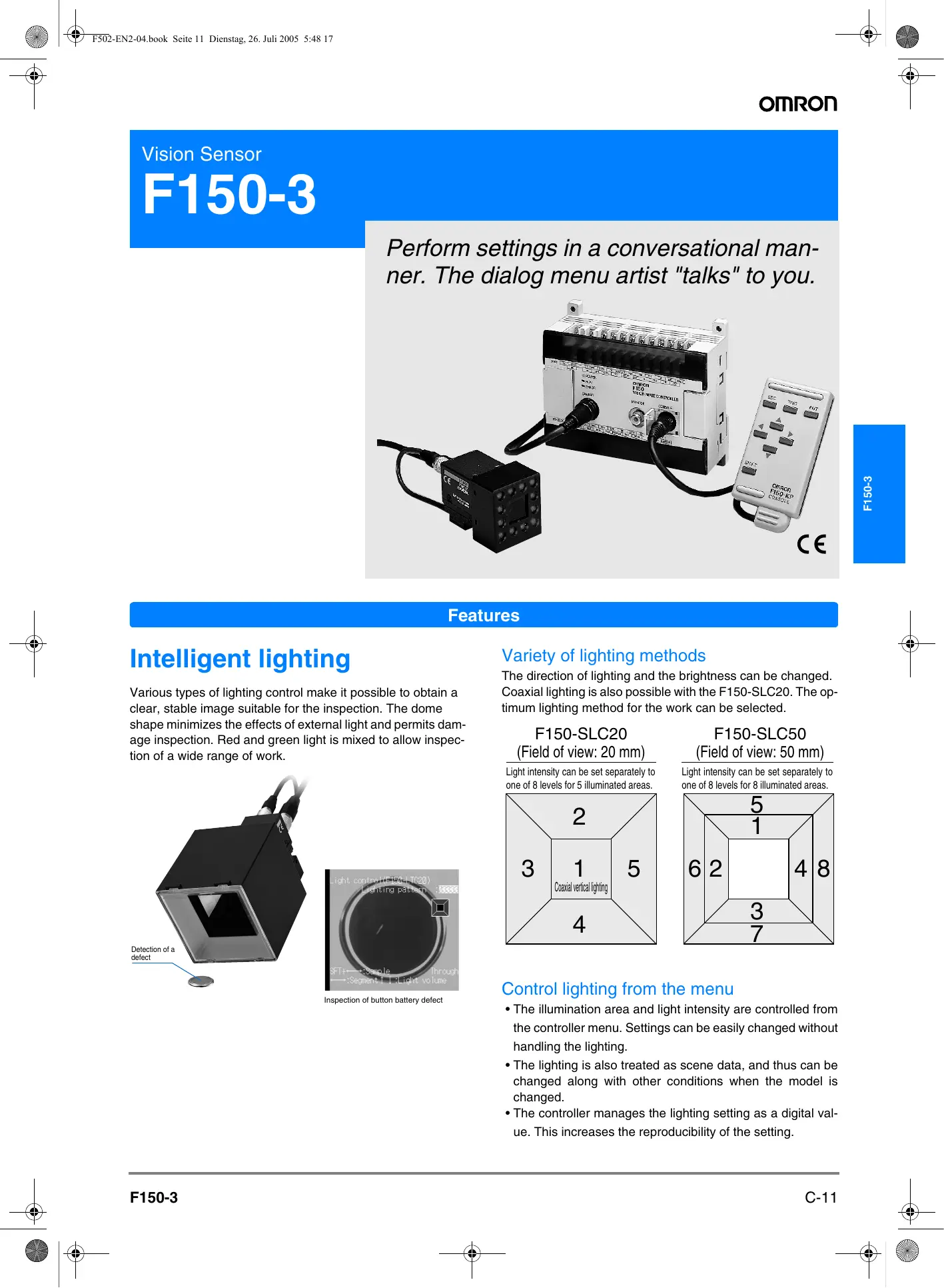
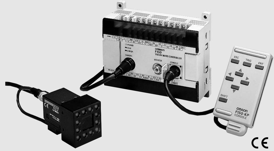
Perform settings in a conversational manner. The dialog menu artist "talks" to you.
Features
Intelligent lighting
Various types of lighting control make it possible to obtain a clear, stable image suitable for the inspection. The dome shape minimizes the effects of external light and permits damage inspection. Red and green light is mixed to allow inspection of a wide range of work.
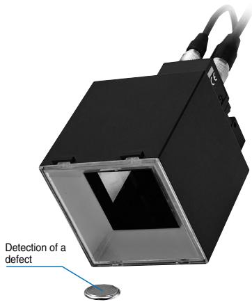
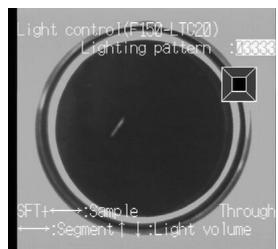
Inspection of button battery defect
Variety of lighting methods
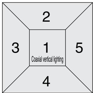
The direction of lighting and the brightness can be changed. Coaxial lighting is also possible with the F150-SLC20. The optimum lighting method for the work can be selected.
F150-SLC20 (Field of view: 20 mm)
Light intensity can be set separately to one of 8 levels for 5 illuminated areas.
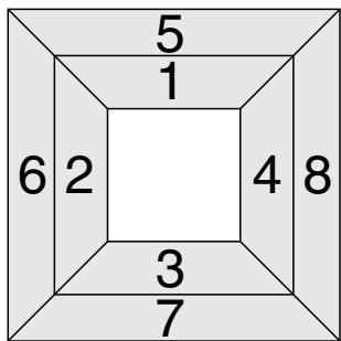
F150-SLC50 (Field of view: 50 mm)
Light intensity can be set separately to one of 8 levels for 8 illuminated areas.
Control lighting from the menu
- The illumination area and light intensity are controlled from the controller menu. Settings can be easily changed without handling the lighting.
- The lighting is also treated as scene data, and thus can be changed along with other conditions when the model is changed.
- The controller manages the lighting setting as a digital value. This increases the reproducibility of the setting.
Features
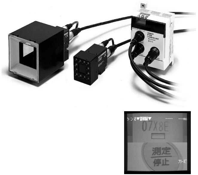
Integrated camera and lens
Camera setup is easy because the object-imaging camera is integrated into a single unit with the lighting apparatus and lens.
2-camera unit
We have made bi-directional, 2-line inspection easy and inexpensive.
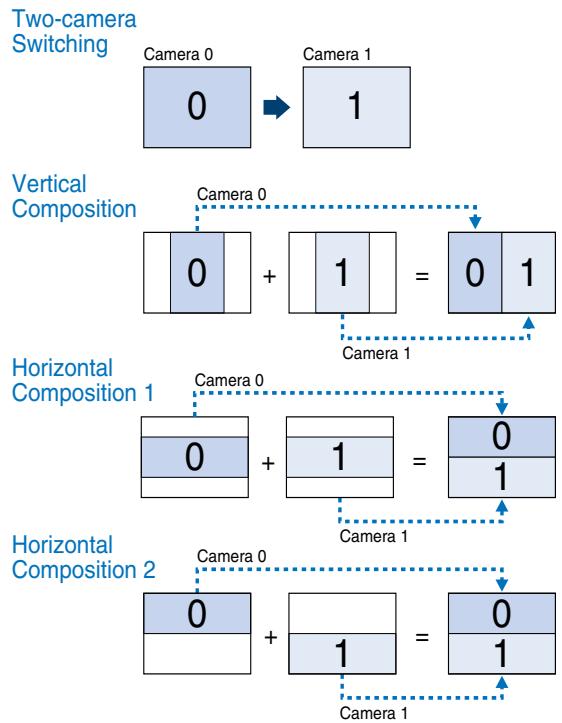
A variety of image read-in methods
Images from two cameras can be read in at the same time. Read-in methods include successive changeover between the two cameras, and combination of the image from each camera into a single image.
Example of application using two cameras
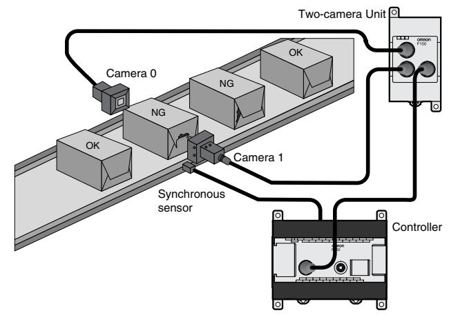
Inspecting Boxes From Both Side
Simultaneously inspect both sides of a box using two cameras.
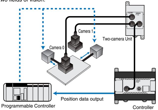
PCB Positioning
Determine the coordinates of position marks using two fields of vision.
Features
Image memory function
Up to 23 inspected images can be stored*.
You can check the image to see what kind of defect occurred. This serves as an aid to maintaining and improving the production line.
With respect to a stored image, measurement can be repeated and measurement conditions changed. This enables a dramatic reduction in setup time during initial installation.
*Can be stored before power is turned off. Storage of all images, including "good" images, is also possible.
To production line


Object


Improper product 3
Good product 3
Improper product 23
Good product 1
Good product 2
Improper product 1
Improper product 2

Good product image
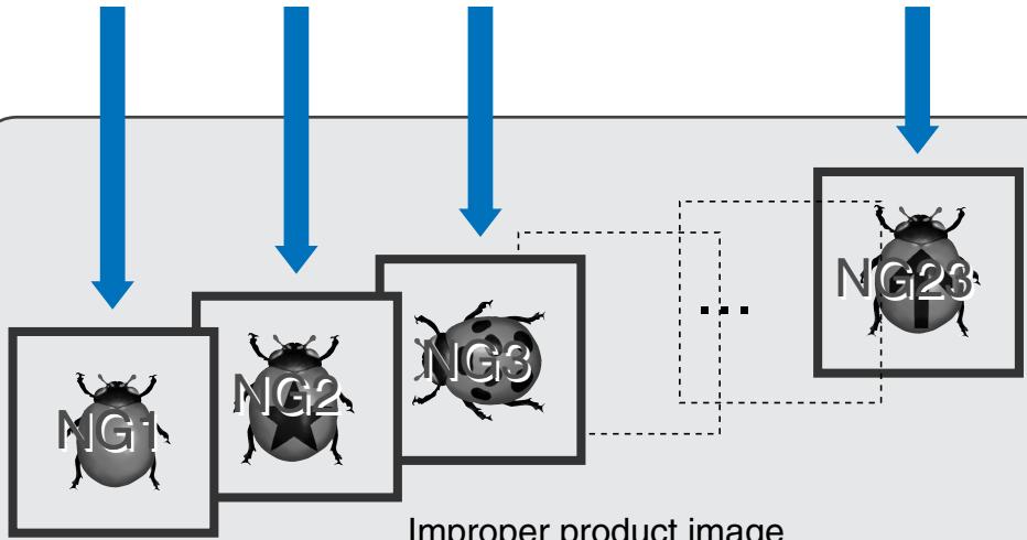
Improper product image
Features
Compact frame shutter camera
- Compact with high resolution.
- An all-pixel reading method and square lattice CCD make it possible to obtain a clear and detailed image suitable for image processing.
- Equipped with an electronic shutter to handle high-speed lines.
- The shutter speed can be adjusted for each scene from the menu. Select the optimum shutter speed for the line speed and work.
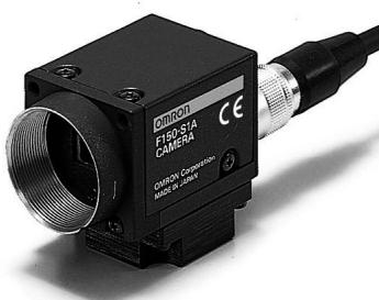
Image pre-processing
- Pre-processing such as smoothing, edge enhancement, edge extraction, and background cut-off allow you to obtain the optimum image for the inspection.
- Pre-processing can be performed in real time (simultaneously with image read-in).
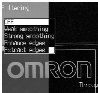
Original image
Edge extraction
High-precision gray search
- Position measurement at sub-pixel precision is possible using 256 graduation gray search processing. This feature is ideal for high-precision positioning applications.
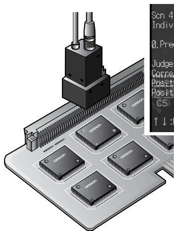
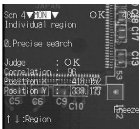
Measurement of fiducial mark positions on a printed circuit board
Damage/dirt inspection
- Omron's proprietary algorithm enables fast and detailed inspection for visual defects such as chips, nicks, burrs, and dirt.
- Linear, circular and rectangular areas can be set, enabling inspection for a variety of defect shapes.


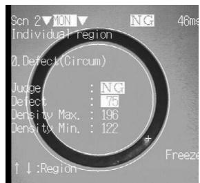
Rubber packing flare inspection
Gray edge measurement
- High-precision (sub-pixel) measurement of work edge position is possible. Ideal for width and dimension inspection.
- Includes edge number and pitch measurement functions for support of IC and connector lead inspection.

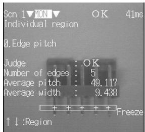
Connector pin-pitch inspection
Output computation functions
- Measurement data computations such as the four arithmetical operations, minimum, maximum, distance between two points, and angle can be set from the menu.
- Up to 24 computations can be set, and decision and data output can be performed based on the computation results.

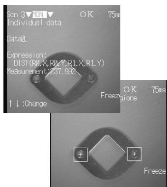
Hole-to-hole distance computation
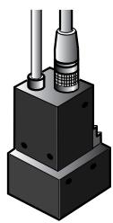
Cameras
Camera with Intelligent Light Source: F150-SLC20
(Field of view: 20mm )
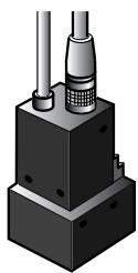
Camera with Intelligent Light Source: F150-SLC50
(Field of view: 50mm )
Camera with Light Source:
F150-SL20
(Field of view: 20mm )
F150-SL50
(Field of view: 50~mm )

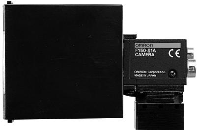
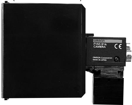
F150-S1A
Camera

When using this camera, please look at "Cameras, lens, and lighting".
- When the size and view of a measurement item do not suit, please use a general CCTV lens and general lighting.
Camera with intelligent lighting
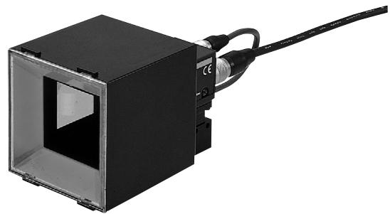
Camera with lighting
Model
| Field of view: 20 mm | F150-SLC20 |
| Field of view: 50 mm | F150-SLC50 |
^* A lens and intelligent lighting are installed on the special camera (F150-S1A) for the F150.
| Field of view: 20 mm | F150-SL20A |
| Field of view: 50 mm | F150-SL50A |
^* A lens and lighting are installed on the special camera (F150-S1A) for the F150.
Distance to inspection object and field of view
The camera distance is fixed.
Fix the camera at a distance that allows correct imaging of the inspected object.
F150-SLC20
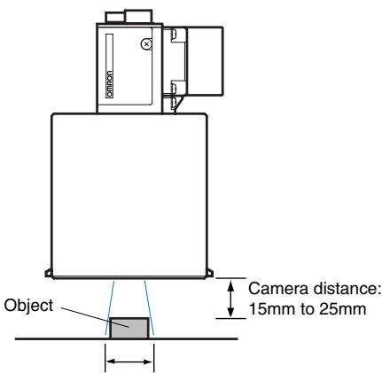
Field of view (20 x 20 mm)
F150-SL20A
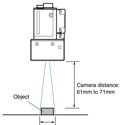
Field of view (20 x 20 mm)
F150-SLC50
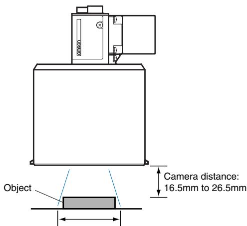
Field of view (50 x 50 mm)
F150-SL50A
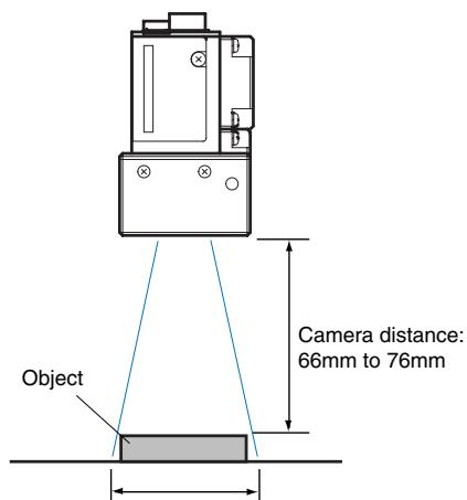
Field of view (50 x 50 mm)
Ordering Information
| Name | Model | |
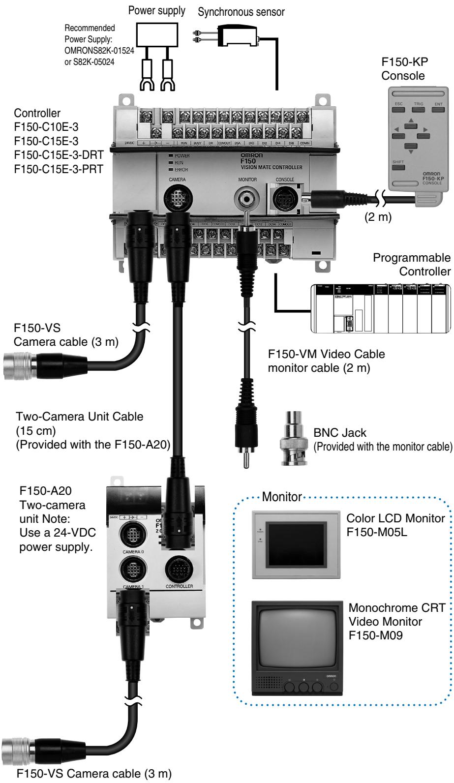
| Controller | F150-C10E-3 (NPN) F150-C15E-3 (PNP) | |
| F150-C10E-3-DRT (Compo Bus/D) F150-C15E-3-PRT (PROFIBUS) | ||
| Camera | Camera with intelligent lighting | F150-SLC20 |
| F150-SLC50 | ||
| Camera with lighting | F150-SL20A | |
| F150-SL50A | ||
| Camera only | F150-S1A | |
| 2-camera unit | F150-A20 | |
| Console | F150-KP | |
| LCD monitor | F150-M05L | |
| Video monitor | F150-M09 | |
| Camera cable 3 m | F150-VS | |
| Monitor cable 2 m | F150-VM | |
Controller: F150-C10E-3/C15E-3 and F150-C15E-3-PRT/DRT
| Item | Specifications |
| Number of con- nected cameras | 1 unit / 2 units (using the F150-A20) |
| Processing resolution | 512 (H) x 484 (V) |
| Number of scenes | 16 scenes (can be saved to a computer through the RS-232C) |
| Image memory function | Up to 23 images can be saved |
| Processing method | Grey Levels (256) / Binary |
| Image pre-processing | Smoothing, edge enhancement, edge extraction, background cut-off |
| Binary Levels | 256 levels (per measurement area) |
| Position correc- tion function | Correction directions: X, Y, Detection modes: binary center of gravity / main axis angle, model position: middle point, edge position |
| Number of mea- surement areas | 16 areas/scene |
| Measured data | Area center of gravity, main axis angle, dark-light correlation value, dark-light search position, defect degree, edge position, edge number, density average, relative position |
| Calculation functions | Four arithmetic operations, distance, maximum value / minimum value, absolute value, others |
| Result output | Overall decision, computation result (decision) per measurement area, measurement/computation data (RS-232C and parallel output possible) |
| Monitor | 1 ch (supports pin jack and over-scan monitor) |
| RS-232C | 1 ch (Dsub 9-pin, female) |
| CompoBus/D | 1 ch (F150-C10E-3-DRT) |
| PROFIBUS-DP | 1 ch (F150-C15E-3-PRT) |
| Parallel input/output | F150-C10E-3 and F150-C15E-3: Inputs: 11points, outputs: 21 points F150-C10E-3-PRT/DRT: Inputs: 1 point, outputs: 5 points (including control inputs/outputs) |
| Power supply voltage | 20.4 to 26.4 VDC |
| Current consumption | Approximately 0.5 A |
| Ambient temperature | Operating: 0 to +50°C, storage: -25 to +65°C (no ice formation or condensation) |
| Ambient humidity | Operating/storage: 35 to 85% RH (with no condensation) |
| Weight (Packed state) | Approximately 940 g (controller: 390 g) |
| Accessories | Three manuals, CompoBus/D connector (DRT type only), PROFIBUS-DP connector (PRT type only) |
Camera
Camera with intelligent lighting: F150-SLC20/50
Camera with lighting: F150-SLC20A/50A
| Item | Specifications | |
| Camera | Image pick-up | 1/3 inch CCD |
| Effective pixels | 659(H) x 494(V) | |
| Shutter function | Electronic frame shutter Shutter speed: 1/100, 1/500, 1/2000, 1/10000 sec (can be changed from the menu) | |
| Lens | Installation distance | F150-SLC20: 15 to 25 mm, F150-SLC50: 16.5 to 26.5 mm, F150-SL20A: 61 to 71 mm, F150-SL50A: 66 to 76 mm |
| Field of view | F150-SLC20/SL20A:20 mm², F150-SLC50/SL50A:50 mm² | |
| Lighting unit | Light source | F150-SLC20/50: Red LED - green LED mixed F150-SL20A/50A: Red LED |
| Light emission method | Pulse emission (synchronized with camera shutter) | |
| Ambient temperature | Operating: 0 to +50°C, storage: -25 to +60°C (no icing or condensation) | |
| Ambient humidity | Operating/storage: 35 to 85% RH (with no condensation) | |
| Weight * Unit only | F150-SLC20: Approximately 280 g F150-SLC50: Approximately 370 g F150-SL20A/50A: Approximately 135 g F150-S1A: Approximately 80 g | |
| Accessories | Instruction manual | |
Two-camera unit: F150-A20
| Item | Specifications |
| Number of connected cameras | 2 units |
| Camera mode | Two-camera switching, vertical division composite, horizontal division composite 1/2, one camera single-stand (camera 0/1) |
| Supply voltage | 20.4 to 26.4 VDC |
| Current consumption | Approximately 0.3 A |
| Ambient temperature | Operating: 0 to +50°C, storage: -25 to +65°C (no ice formation or condensation) |
| Ambient humidity | Operating/storage: 35 to 85% RH (with no condensation) |
| Weight * Unit only | Approx. 220 g |
| Accessories | Operation manual, camera unit cable (1) |
Note: Can be connected to an F150-C10-3 controller.
Monitor
| Item | Product name name Model | LCD monitor F150-M05L | Video monitor F150-MON |
| Size | 5.5 type | 9 inches | |
| Type | TFT color LCD | CRT monochrome | |
| Resolution | 320 x 240 dots | 800TV or higher (center) | |
| Input signal | NTSC composite video (1.0 V / 75 ) | ||
| Supply voltage | 20.4 to 26.4 VDC | 100 to 240 VAC(-15%, +10%) | |
| Current consumption | Approx. 700 mA | Approx. 200 mA | |
| Ambient temperature | Operating: 0 to +50°C, storage: -25 to +65°C(no ice formation or condensation) | Operating: -10 to +50°C, storage: -20 to +65°C(no ice formation or condensation) | |
| Ambient humidity | Operating/storage:35 to 85% RH (no ice formation or condensation) | 10 to 90-RH (No condensation) | |
| Weight *Unit only | Approx. 1 kg | Approx. 4.5 kg | |
| Accessories | Operation manual, clamps(4) | Instruction manual | |
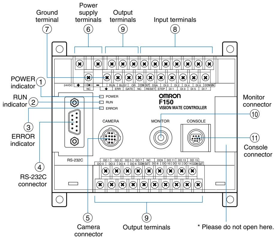
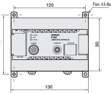
F150-C10E-3/F150-C15E-3
① Lit while power is ON.
② Lit while the F150 is in Run Mode.
③ Lit when an error has occurred.
④ Connects the F150 to external devices such as personal computers or programmable controllers.
⑤ Connects the F150 to camera or two-camera unit.
⑥ Connects to the power supply.
⑦ Connects to the ground wire.
⑧ ⑨ Connects to the F150 to external devices such as synchronous sensors or programmable controllers.
⑩ Connects to the monitor.
① Connects to the console.
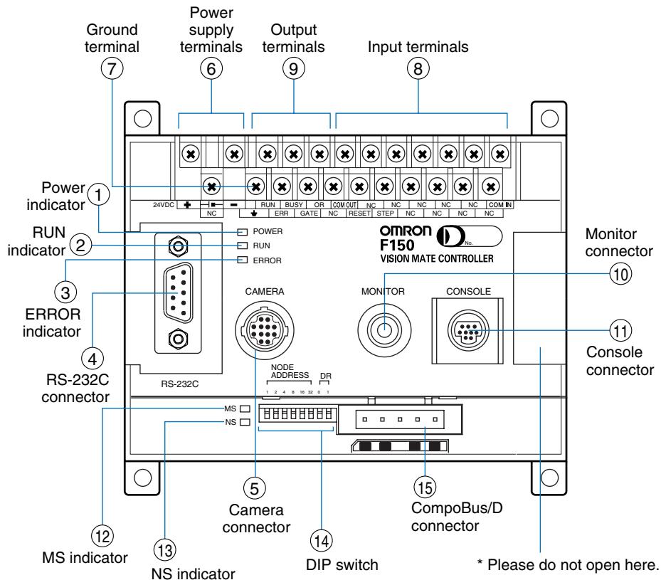
F150-C10E-3-DRT (CompoBus/D (DeviceNet) type)
① Lit while power is ON.
② Lit while the F150 is in Run Mode.
③ Lit when an error has occurred.
④ Connects the F150 to external devices such as personal computers or programmable controllers.
⑤ Connects the F150 to camera or two-camera unit.
⑥ Connects to the power supply.
⑦ Connects to the ground wire.
(8) (9) Connects to the F150 to external devices such as synchronous sensors or programmable controllers.
⑩ Connects to the monitor.
① Connects to the console.
12 Indicates the state of F150 in CompoBus/D communication.
13 Indicates the state of F150 in CompoBus/D communication.
(4) Set up the node address and communication speed of CompoBus/D communication.
(15) Connects to the communication cable of a CompoBus/D network.
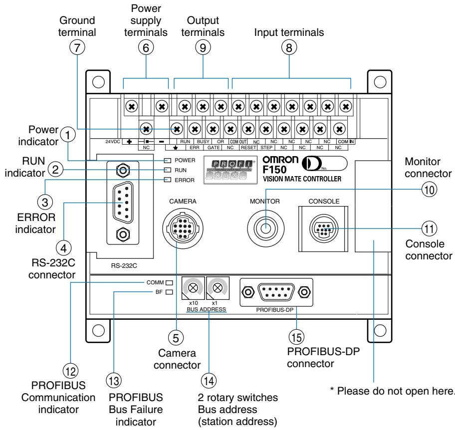
F150-C15E-3-PRT (PROFIBUS-DP type)
① Lit while power is ON.
② Lit while the F150 is in Run Mode.
③ Lit when an error has occurred.
④ Connects the F150 to external devices such as personal computers or programmable controllers.
⑤ Connects the F150 to camera or two-camera unit.
⑥ Connects to the power supply.
⑦ Connects to the ground wire.
8 Connects to the F150 to external devices such as synchronous sensors or programmable controllers.
⑥ Connects to the monitor.
⑪ Connects to the console.
12 Indicates the state of F150 in PROFIBUS-DP communication.
13 Indicates the state of F150 in PROFIBUS-DP communication.
14 Set up the node address of PROFIBUS-DP communication.
⑤ Connects to the communication cable of a PROFIBUS-DP network.
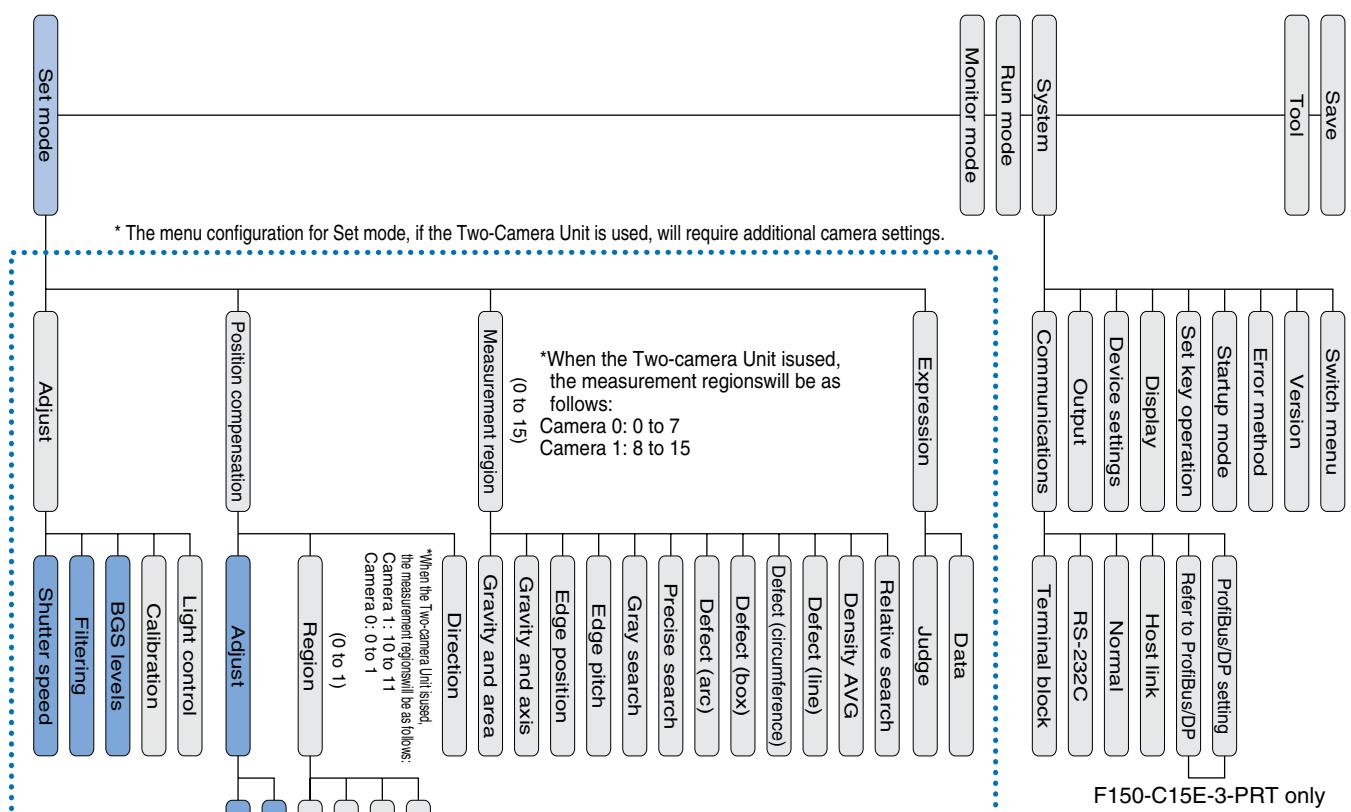
Function menu
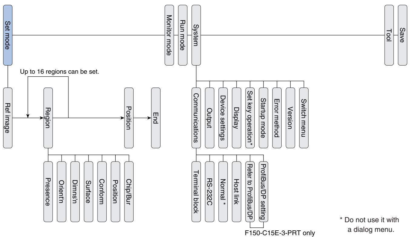
Menu structure diagram
Dialog menu
Expert menu
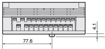
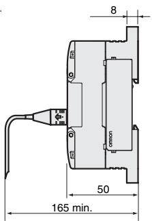
Controller
F150-C10E-3, F150-C50E-3,
F150-C15E-3-PRT,
F150-C10E-3-DRT
Console
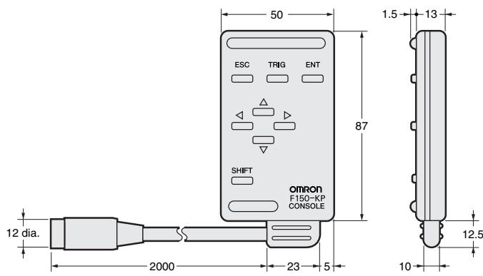
F150-KP
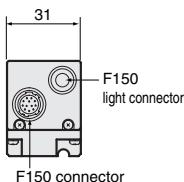
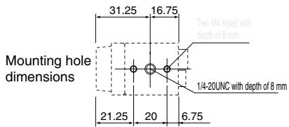
Camera
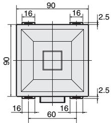
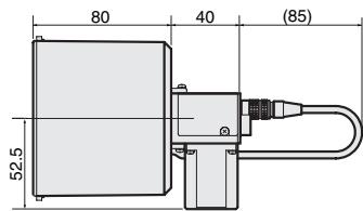
F150-SLC20 (camera with F150-LTC20 intelligent lighting)
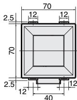
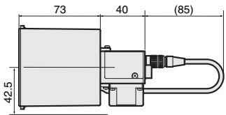
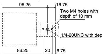
Mounting dimensions
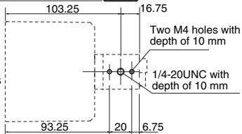
F150-SLC50 (camera with F150-LTC50 intelligent lighting)
Mounting dimensions
F150-SL20A/SL50A (camera with lighting)

Mounting dimensions
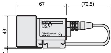
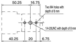
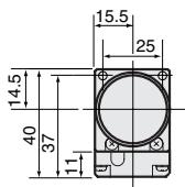
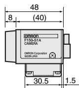
F150-S1A (camera only)
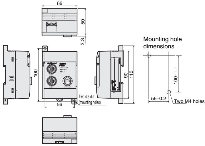
2-camera unit
F150-A20
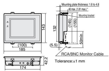
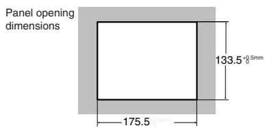
LCD monitor
F150-M05L
CRT monitor
F150-M09
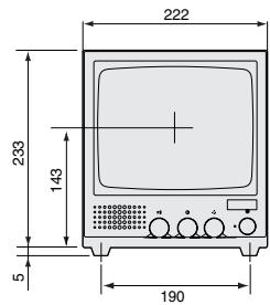
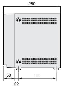
ALL DIMENSIONS SHOWN ARE IN MILLIMETERS.
To convert millimeters into inches, multiply by 0.03937. To convert grams into ounces, multiply by 0.03527.