
DEVICENET SAFETY - Industrial electronic component OMRON - Free user manual and instructions
Find the device manual for free DEVICENET SAFETY OMRON in PDF.
| Product Type | Safety I/O Terminal DST1 series |
| Available models | DST1-ID12SL-1 (12 inputs), DST1-MD16SL-1 (8 inputs + 8 outputs), DST1-MRD08SL-1 (4 inputs + 4 relay outputs), DST1-XD0808SL-1 (8 inputs + 8 outputs with integrated logic) |
| Dimensions (W x H x D) | Approx. 70 x 100 x 70 mm (depending on model) |
| Weight | Approx. 150 g (max 200 g depending on model) |
| Power supply | 24 VDC via DeviceNet bus (communication power) and external I/O power supply 24 VDC |
| Power consumption | Typical 100 mA (bus) + 50 mA (I/O) per terminal |
| Main functions | Safety inputs with test pulses, safety outputs (semiconductor or relay), test outputs, integrated logic (XD0808SL), DeviceNet Safety communication, self-diagnosis, error history, password protection |
| Safety inputs | 12 (ID12), 8 (MD16, XD0808), 4 (MRD08); external fault detection, configurable On/Off delays, dual-channel mode |
| Safety outputs | 8 semiconductor outputs (MD16, XD0808) or 4 relay outputs (MRD08); max current 0.5 A (semiconductor) or 2 A (relay); test pulses, dual-channel mode |
| Test outputs (T0 to T3) | 4 configurable outputs: pulsed test output, standard output, sensor power supply, muting lamp output (T3) |
| Network protocol | DeviceNet Safety (IEC 61508 SIL 3, EN 954-1 Category 4) and standard DeviceNet |
| Diagnostic functions | Input/output test pulses, short-circuit detection, overcurrent, wiring fault, discrepancy time |
| Maintenance functions | Contact operation counter, conduction time monitor, error logging, last maintenance date |
| Care and cleaning | Regular cleaning with dry cloth; periodic inspection of connections and indicators; relay replacement (MRD08) every 6 months max |
| Safety | Certifications TÜV Rheinland, UL 1998/508/1604; compliance with SIL 3, Category 4; emergency stop, door lock, safety sensors |
| Spare parts and repairability | Output relay (DST1-MRD08SL-1), connectors, fuses (3.15 A for relay); repair not recommended, replace unit |
| General information | Brand: OMRON; series: DeviceNet Safety; free user manual (142 pages) |
Frequently Asked Questions - DEVICENET SAFETY OMRON
User questions about DEVICENET SAFETY OMRON
0 question about this device. Answer the ones you know or ask your own.
Ask a new question about this device
Download the instructions for your Industrial electronic component in PDF format for free! Find your manual DEVICENET SAFETY - OMRON and take your electronic device back in hand. On this page are published all the documents necessary for the use of your device. DEVICENET SAFETY by OMRON.
USER MANUAL DEVICENET SAFETY OMRON
Safety I/O Terminals
OPERATION MANUAL
DST1-series Safety I/O Terminals Operation Manual
Revised March 2008
Notice:
OMRON products are manufactured for use according to proper procedures by a qualified operator and only for the purposes described in this manual.
The following conventions are used to indicate and classify precautions in this manual. Always heed the information provided with them. Failure to heed precautions can result in injury to people or damage to property.

DANGER
Indicates an imminently hazardous situation which, if not avoided, is likely to result in serious injury or may result in death. Additionally, there may be severe property damage.

WARNING
Indicates a potentially hazardous situation which, if not avoided, will result in minor or moderate injury or may result in serious injury or death. Additionally, there may be severe property damage.

Caution
Indicates a potentially hazardous situation which, if not avoided, may result in minor or moderate injury or in property damage.

Indicates required actions.

Indicates prohibited actions.
OMRON Product References
All OMRON products are capitalized in this manual. The word “Unit” is also capitalized when it refers to an OMRON product, regardless of whether or not it appears in the proper name of the product.
The abbreviation “PLC” means Programmable Controller. “PC” is used, however, in some Programming Device displays to mean Programmable Controller.
Visual Aids
The following headings appear in the left column of the manual to help you locate different types of information.
IMPORTANT Indicates important information on what to do or not to do to prevent failure to operation, malfunction, or undesirable effects on product performance.
Note Indicates information of particular interest for efficient and convenient operation of the product.
1,2,3... 1. Indicates lists of one sort or another, such as procedures, checklists, etc.
Trademarks and Copyrights
DeviceNet and DeviceNet Safety are registered trademarks of the Open DeviceNet Vendors Association.
Other product names and company names in this manual are trademarks or registered trademarks of their respective companies.
The copyright of the DeviceNet Safety DST1-series Safety I/O Terminals belongs to OMRON Corporation.
© OMRON, 2005
All rights reserved. No part of this publication may be reproduced, stored in a retrieval system, or transmitted, in any form, or by any means, mechanical, electronic, photocopying, recording, or otherwise, without the prior written permission of OMRON.
No patent liability is assumed with respect to the use of the information contained herein. Moreover, because OMRON is constantly
striving to improve its high-quality products, the information contained in this manual is subject to change without notice. Every precaution has been taken in the preparation of this manual. Nevertheless, OMRON assumes no responsibility for errors or omissions. Neither is any liability assumed for damages resulting from the use of the information contained in this publication.
TABLE OF CONTENTS
PRECAUTIONS...... XV
1 Intended Audience.... xvi
2 General Precautions.... xvi
3 Safety Precautions ...... xviii
4 Operating Environment Precautions ...... xix
5 Additional Precautions According to UL1604 ..... xxi
6 Regulation and Standards ..... xxi
7 Glossary.... xxii
SECTION 1 Overview .... 1
1-1 Overview 2
1-2 Standard Models 5
1-3 Functions 6
1-4 Description of Safety Functions 9
1-5 Logic Functions.... 17
SECTION 2 General Procedure .... 21
2-1 General Procedure 22
2-2 Installation.... 23
2-3 Connecting I/O Power and I/O Cable 24
2-4 Connecting the Communications Connector.... 26
2-5 Node Address.... 27
2-6 Configuration.... 27
SECTION 3 Configuration .... 29
3-1 Editing Device Parameters.... 30
3-2 Remote I/O Allocations.... 37
SECTION 4 Specifications.... 53
4-1 Specifications.... 54
4-2 Indicators 56
SECTION 5 DST1 Series Specifications.... 59
5-1 DST1-ID12SL-1 60
5-2 DST1-MD16SL-1 63
5-3 DST1-MRD08SL-1 67
5-4 DST1-XD0808SL-1....72
TABLE OF CONTENTS
SECTION 6
Response Performance.... 77
6-1 Reaction Time 78
SECTION 7
Troubleshooting and Maintenance 79
7-1 Indicators and Error Processing.... 80
7-2 Troubleshooting.... 81
7-3 Error History 84
7-4 Maintenance.... 86
SECTION 8
Wiring Examples.... 89
8-1 Wiring and Configuration 90
8-2 Examples of Wiring for Each Application 91
8-3 Logic Terminal Wiring Examples 99
Appendix 103
Index.... 117
Revision History 121
About this Manual:
This manual describes the installation and operation of a DST1-series Safety I/O Terminals (referred to as the DST1 in this manual).
Please read this manual carefully and be sure you understand the information provided before attempting to install or operate the DST1. Be sure to read the precautions provided in the following section.
The following manuals provide information on the DeviceNet and DeviceNet Safety.
| Manual | Products | Contents | Cat. No. |
| DeviceNet Safety DST1-series Safety I/O Terminals Operation Manual (This manual) | DST1-series Safety I/O Terminals | Information on DST1-series Safety I/O Terminals | Z904 |
| DeviceNet Safety System Configuration Manual | WS02-CFSC1-E | Information on using the Network Configurator | Z905 |
| DeviceNet Safety Network Controller Operation Manual | NE1A Series: NE1A-SCPU01(-V1)/-SCPU02 | Specifications, performance information, and operating procedure for NE1A-series Safety Network Controllers. | Z906 |
| DeviceNet Safety NE0A Series Safety Network Controller Operation Manual | NE0A Series: NE0A-SCPU01 | Specifications, functions, and usage of the NE0A-series Safety Network Controllers. | Z916 |
| DeviceNet Operation Manual | Describes the network configuration and connection modes of a DeviceNet network. Also provides details on connection methods, specifications, and power supply methods to the communications systems of connection devices, such as cables and connectors. | W267 | |

WARNING
Failure to read and understand the information provided in this manual may result in personal injury or death, damage to the product, or product failure. Please read each section in its entirety and be sure you understand the information provided in the section and related sections before attempting any of the procedures or operations given.
Read and Understand this Manual
Please read and understand this manual before using the product. Please consult your OMRON representative if you have any questions or comments.
Warranty and Limitations of Liability
WARRANTY
OMRON's exclusive warranty is that the products are free from defects in materials and workmanship for a period of one year (or other period if specified) from date of sale by OMRON.
OMRON MAKES NO WARRANTY OR REPRESENTATION, EXPRESS OR IMPLIED, REGARDING NON-INFRINGEMENT, MERCHANTABILITY, OR FITNESS FOR PARTICULAR PURPOSE OF THE PRODUCTS. ANY BUYER OR USER ACKNOWLEDGES THAT THE BUYER OR USER ALONE HAS DETERMINED THAT THE PRODUCTS WILL SUITABLY MEET THE REQUIREMENTS OF THEIR INTENDED USE. OMRON DISCLAIMS ALL OTHER WARRANTIES, EXPRESS OR IMPLIED.
LIMITATIONS OF LIABILITY
OMRON SHALL NOT BE RESPONSIBLE FOR SPECIAL, INDIRECT, OR CONSEQUENTIAL DAMAGES, LOSS OF PROFITS OR COMMERCIAL LOSS IN ANY WAY CONNECTED WITH THE PRODUCTS, WHETHER SUCH CLAIM IS BASED ON CONTRACT, WARRANTY, NEGLIGENCE, OR STRICT LIABILITY.
In no event shall the responsibility of OMRON for any act exceed the individual price of the product on which liability is asserted.
IN NO EVENT SHALL OMRON BE RESPONSIBLE FOR WARRANTY, REPAIR, OR OTHER CLAIMS REGARDING THE PRODUCTS UNLESS OMRON'S ANALYSIS CONFIRMS THAT THE PRODUCTS WERE PROPERLY HANDLED, STORED, INSTALLED, AND MAINTAINED AND NOT SUBJECT TO CONTAMINATION, ABUSE, MISUSE, OR INAPPROPRIATE MODIFICATION OR REPAIR.
Application Considerations
SUITABILITY FOR USE
OMRON shall not be responsible for conformity with any standards, codes, or regulations that apply to the combination of products in the customer's application or use of the products.
At the customer's request, OMRON will provide applicable third party certification documents identifying ratings and limitations of use that apply to the products. This information by itself is not sufficient for a complete determination of the suitability of the products in combination with the end product, machine, system, or other application or use.
The following are some examples of applications for which particular attention must be given. This is not intended to be an exhaustive list of all possible uses of the products, nor is it intended to imply that the uses listed may be suitable for the products:
- Outdoor use, uses involving potential chemical contamination or electrical interference, or conditions or uses not described in this manual.
- Nuclear energy control systems, combustion systems, railroad systems, aviation systems, medical equipment, amusement machines, vehicles, safety equipment, and installations subject to separate industry or government regulations.
- Systems, machines, and equipment that could present a risk to life or property.
Please know and observe all prohibitions of use applicable to the products.
NEVER USE THE PRODUCTS FOR AN APPLICATION INVOLVING SERIOUS RISK TO LIFE OR PROPERTY WITHOUT ENSURING THAT THE SYSTEM AS A WHOLE HAS BEEN DESIGNED TO ADDRESS THE RISKS, AND THAT THE OMRON PRODUCTS ARE PROPERLY RATED AND INSTALLED FOR THE INTENDED USE WITHIN THE OVERALL EQUIPMENT OR SYSTEM.
PROGRAMMABLE PRODUCTS
OMRON shall not be responsible for the user's programming of a programmable product, or any consequence thereof.
Disclaimers
| CHANGE IN SPECIFICATIONS |
| Product specifications and accessories may be changed at any time based on improvements and other reasons.It is our practice to change model numbers when published ratings or features are changed, or when significant construction changes are made. However, some specifications of the products may be changed without any notice. When in doubt, special model numbers may be assigned to fix or establish key specifications for your application on your request. Please consult with your OMRON representative at any time to confirm actual specifications of purchased products. |
| DIMENSIONS AND WEIGHTS |
| Dimensions and weights are nominal and are not to be used for manufacturing purposes, even when tolerances are shown. |
| PERFORMANCE DATA |
| Performance data given in this manual is provided as a guide for the user in determining suitability and does not constitute a warranty. It may represent the result of OMRON's test conditions, and the users must correlate it to actual application requirements. Actual performance is subject to the OMRON Warranty and Limitations of Liability. |
| ERRORS AND OMISSIONS |
| The information in this manual has been carefully checked and is believed to be accurate; however, no responsibility is assumed for clerical, typographical, or proofreading errors, or omissions. |
PRECAUTIONS
1 Intended Audience ..... xvi
2 General Precautions ...... xvi
3 Safety Precautions.... xviii
4 Operating Environment Precautions xix
5 Additional Precautions According to UL1604 ..... xxi
6 Regulation and Standards ..... xxi
7 Glossary xxii
1 Intended Audience
This manual is intended for the following personnel, who must have knowledge of electrical systems (an electrical engineer or the equivalent).
- Personnel in charge of introducing FA and safety systems into production facilities
- Personnel in charge of designing FA and safety systems
- Personnel in charge of managing FA facilities
- Personnel who have the qualifications, authority, and obligation to provide safety during each of the following product phases: mechanical design, installation, operation, maintenance, and disposal
2 General Precautions
The user must operate the product according to the performance specifications described in the operation manuals.
Before using the product under conditions which are not described in the manual or applying the product to nuclear control systems, railroad systems, aviation systems, vehicles, combustion systems, medical equipment, amusement machines, safety equipment, and other systems, machines, and equipment that may have a serious influence on lives and property if used improperly, consult your OMRON representative.
Make sure that the ratings and performance characteristics of the product are sufficient for the systems, machines, and equipment, and be sure to provide the systems, machines, and equipment with double safety mechanisms.
This manual provides information for programming and operating the Unit. Be sure to read this manual before attempting to use the Unit and keep this manual close at hand for reference during operation.
! WARNING
It is extremely important that a PLC and all PLC Units be used for the specified purpose and under the specified conditions, especially in applications that can directly or indirectly affect human life. You must consult with your OMRON representative before applying a PLC System to the above-mentioned applications.
! WARNING
This is the Operation Manual for the DST1-series Safety I/O Terminals. Heed the following items during system construction to ensure that safety-related components are configured in a manner that allows the system functions to sufficiently operate.
- Risk Assessment
The proper use of the safety device described in this Operation Manual as it relates to installation conditions and mechanical performance and functions is a prerequisite for its use. When selecting or using this safety device, risk assessment must be conducted with the aim of identifying potential danger factors in equipment or facilities in which the safety device is to be applied, during the development stage of the equipment or facilities. Suitable safety devices must be selected under the guidance of a sufficient risk assessment system. An insufficient risk assessment system may lead to the selection of unsuitable safety devices.
- Typical related international standards: ISO 14121, Safety of Machinery -- Principles of Risk Assessment
- Safety Measures
When using this safety device to build systems containing safety-related components for equipment or facilities, the system must be designed with the full understanding of and conformance to international standards, such as those listed below, and/or standards in related industries.
- Typical related international standards: ISO/DIS 12100, Safety of Machinery -- Basic Concepts and General Principles for Design IEC 61508, Safety Standard for Safety Instrumented Systems (Functional Safety of Electrical/Electronic/Programmable Electronic Safety-related Systems)
• Role of Safety Device
This safety device is provided with safety functions and mechanisms as stipulated in relevant standards, but suitable designs must be used to allow these functions and mechanisms to operate properly inside system constructions containing safety-related components. Build systems that enable these functions and mechanisms to perform properly, based on a full understanding of their operation.
- Typical related international standards: ISO 14119, Safety of Machinery -- Interlocking Devices Associated with Guards -- Principles of Design and Selection
• Installation of Safety Device
The construction and installation of systems with safety-related components for equipment or facilities must be performed by technicians who have received suitable training.
- Typical related international standards: ISO/DIS 12100, Safety of Machinery -- Basic Concepts and General Principles for Design IEC 61508, Safety Standard for Safety Instrumented Systems (Functional Safety of Electrical/Electronic/Programmable Electronic Safety-related Systems)
- Complying with Laws and Regulations
This safety device conforms to the relevant regulations and standards, but make sure that it is used in compliance with local regulations and standards for the equipment or facilities in which it is applied.
- Typical related international standards: IEC 60204, Safety of Machinery -- Electrical Equipment of Machines
- Observing Precautions for Use
When putting the selected safety device to actual use, heed the specifications and precautions in this Operation Manual and those in the Instruction Manual that comes with the product. Using the product in a manner that deviates from these specifications and precautions will lead to unexpected failures in equipment or devices, and to damages that result from such failures, due to insufficient operating functions in safety-related components.
- Moving or Transferring Devices or Equipment
When moving or transferring devices or equipment, be sure to include this Operation Manual to ensure that the person to whom the device or equipment is being moved or transferred will be able to operate it properly.
- Typical related international standards: ISO/DIS 12100 ISO, Safety of Machinery -- Basic Concepts and General Principles for Design IEC 61508, Safety Standard for Safety Instrumented Systems (Functional Safety of Electrical/Electronic/Programmable Electronic Safety-related Systems)
3 Safety Precautions
 WARNING WARNING | |
| Serious injury may possibly occur due to loss of required safety functions. Do not use test outputs of the DST1 as any safety outputs. |  |
| Serious injury may possibly occur due to loss of required safety functions. Do not use DeviceNet standard I/O data or Explicit message data as any safety data. |  |
| Serious injury may possibly occur due to loss of required safety functions. Do not use LEDs on the DST1 for safety operations. |  |
| Serious injury may possibly occur due to breakdown of safety outputs. Do not connect loads beyond the rated value to the safety outputs. |  |
| Serious injury may possibly occur due to loss of required safety functions. Wire the DST1 properly so that 24-VDC line do NOT touch the safety outputs accidentally or unintentionally. |  |
| Serious injury may possibly occur due to loss of required safety functions. Ground the 0V line of the power supply for external output devices so that the devices do Not turn ON when the safety output line is grounded. |  |
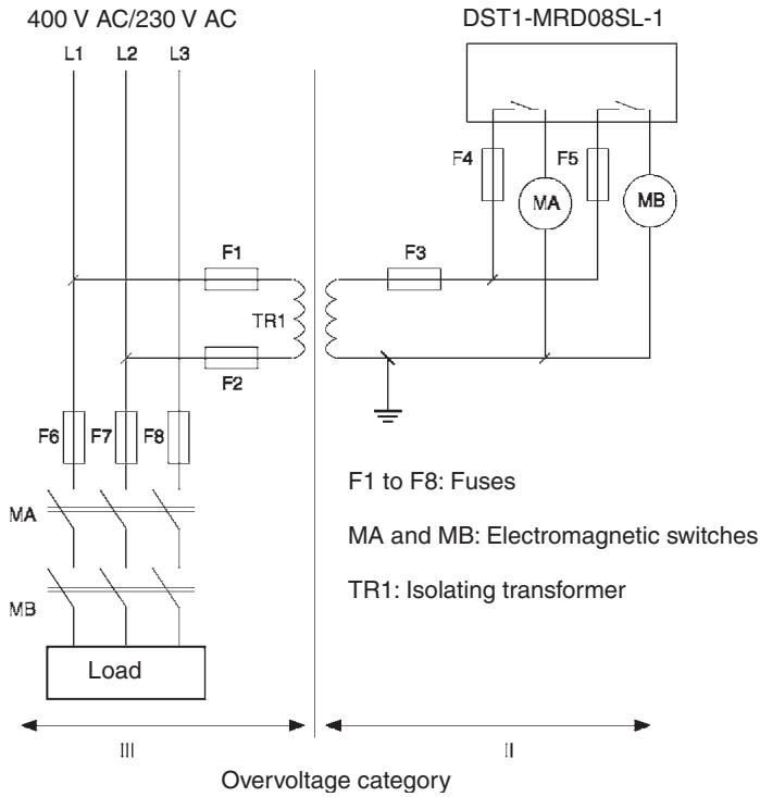
| For the DST1-MRD08SL-1, isolating transformers, such as TR1, that are used to isolate between overvoltage categories III and II must conform to IEC60742, and the insulation between the primary input and secondary output must satisfy at least the basic insulation standards of overvoltage category III. One side of the secondary output of the isolating transformer must be grounded to prevent electrical shock in case of short-circuiting to the ground or to the frame of the isolating transformer. To protect the isolating transformer and to prevent electrical shock in case of short-circuiting to the frame, insert fuses according to transformer specifications, i.e. at points F1, F2, and F3. |  |
 | |
| Serious injury may possibly occur due to loss of required safety functions. Clear the previous configuration data before connecting devices to the network. |  |
| Serious injury may possibly occur due to loss of required safety functions. Set suitable node addresses before connecting devices to the network. |  |
| Serious injury may possibly occur due to loss of required safety functions. Perform user testing and confirm that all device configuration data and operations are correct before starting system operation. |  |
| Serious injury may possibly occur due to loss of required safety functions.When replacing a device, configure the replacement device appropriately and confirm that it operates correctly. |  |
| For Model DST1-MRD08SL-1, insert a fuse rated at 3.15 A or less for each output terminal to protect safety output contacts from welding. Confirm the fuse selection with the fuse manufacturer to ensure the dependability of the characteristics of the connected load. |  |
| Serious injury may possibly occur due to loss of safety functions. Use appropriate devices according to the requirements given in the following table. |  |
| Control device | Requirements |
| Emergency stop switches | Use approved switches with a direct opening mechanism complying with IEC/EN 60947-5-1. |
| Door interlocking switchesLimit switches | Use approved switches with a direct opening mechanism complying with IEC/EN 60947-5-1 and capable of switching micro-loads of 5 mA at 24 V DC. |
| Safety sensors | Use approved sensors complying with the relevant product standards, regulations, and rules in the country where it is used. |
| Relays with forcibly guided contactsContactors | Use approved relays with forcibly guided contacts complying with EN 50205. For feedback purpose, use devices with contacts capable of switching micro-loads of 4 mA at 24 V DC. |
| Other devices | Evaluate whether devices used are appropriate to satisfy the requirements of safety category. |
4 Operating Environment Precautions
■Handle with Care
Do not drop the DST1 to the ground or excessive vibration or mechanical shocks. The DST1 may be damaged and may not function properly.
■Installation and Storage Environment
Do not use or store the DST1 in any of the following locations.
- Locations subject to direct sunlight.
- Locations subject to temperatures or humidity outside the range specified in the specifications.
- Locations subject to condensation as the result of severe changes in temperature.
- Locations subject to dust (especially iron dust) or salts
- Locations subject to dust (especially iron dust) or salts.
- Locations subject to water, oil, or chemicals.
- Locations subject to shock or vibration.
Take appropriate and sufficient countermeasures when installing systems in the following locations. Inappropriate and insufficient measures may result in malfunction.
- Locations subject to static electricity or other forms of noise.
- Locations subject to strong electromagnetic fields
- Locations subject to possible exposure to radioactivity.
- Locations close to power supplies.
This is a class A product. In residential areas it may cause radio interference, in which case the user may be required to take adequate measures to reduce interference.
■Installation/Mounting
- Use the DST1 within an enclosure with IP54 protection or higher of IEC/EN 60529.
- Use DIN rail (TH35-7.5 according to IEC60715) for placing the DST1 into the control board.
- Mount the DST1 to DIN rails with attachments (TYPE PFP-M, not incorporated to this product), not to drop out of rails by vibration etc.
- Spacing should be available around the DST1 at least 50 mm from its top and bottom surfaces for ventilation and wiring.
■Installation/Wiring
- Use the following to wire external I/O devices to the DST1.
| Solid wire | 0.2 to 2.5 mm ^2 AWG 24 to 12 |
| Standard (Flexible) wire | 0.34 to 1.5 mm ^2 AWG 22 to 16Standard wire should be processed with insulation-covered bar terminal (DIN46228-4 standard compatible type) at its ends before using for connection. |
- Disconnect the DST1 from power supply when wiring. Devices connected to DST1 may operate unexpectedly.
- Apply properly specified voltages to the DST1 inputs. Applying inappropriate DC voltage and any AC voltages cause the DST1 to fail.
- Be sure to separate the communication cable and the I/O cable from the high-voltage/ current lines.
- Be cautious not to have your fingers caught when attaching connectors to the plugs on the DST1.
- Mount screw of DeviceNet Connector and I/O Connector correctly. (0.25-0.3 N·m)
- Incorrect wiring may lead to loss of safety function. Wire conductors correctly and verify the operation of the DST1 before commissioning the system in which DST1 is incorporated.
- After wiring is completed, be sure to remove label for wire clipping prevention on the DST1 to enable heat to escape for proper cooling
■ Power Supply Selection
Use DC power supply satisfying requirements below.
- Secondary circuits of DC power supply is isolated from its primary circuit by double insulations or reinforced insulations
- DC power supply satisfies the requirement for class 2 circuits or limited voltage/current circuit stated in UL 508.
- 20 ms or over of the output hold time.
■Periodical Inspection and Maintenance
- Disconnect the DST1 from power supply when replacing. Devices connected to the DST1 may operate unexpectedly.
- Do not dismantle, repair, or modify the DST1. It may lead to loss of its safety functions.
■ Disposal
- Be cautious not to have you injured when dismantling the DST1.
5 Additional Precautions According to UL1604
DST1-ID12SL-1 and DST1-MD16SL-1 are suitable for use in Class I, Div. 2, Group A, B, C, D or Non-Hazardous Location Only.
WARNING - Explosion Hazard - Substitution of Components May Impair Suitability For Class I, Div. 2.
WARNING - Explosion Hazard - Do not Disconnect Equipment Unless Power Has Been Switched Off Or The Area Is Known To Be Non-Hazardous.
6 Regulation and Standards
The DST1 Series has received the following certifications.
| Certifying organization | Standards |
| TÜV Rheinland | IEC 61508 Part 1-7/12.98-05.00EN 954-1: 1996, ISO 13849-1:1999EN /ISO 13849-2: 2003IEC 61131-2: 2003EN 60204-1: 2006EN 61000-6-2: 2001EN 61000-6-4: 2001EN 418: 1992NFPA 79-2002, ANSI RIA15.06-1999, ANSI B11.19-2003 |
| UL (See note.) | UL 1998UL 508UL 1604 (except for DST1-MRD08SL-1)NFPA 79IEC 61508CSA 22.2 No. 142CSA 22.2 No. 213 (except for DST1-MRD08SL-1) |
7 Glossary
| Term | Description |
| idle data | Data sent when the originating application is in an inexecutable state. |
| assembly | Internal data in a device gathered as one group to be accessed externally. |
| safety data | Data with high reliability. |
| error latch time | The time period to hold an error state (control data, status data, and LED indications). |
| open type | The open method for Safety Connection. One of three types is selected in the settings of a connection to the Safety Master. |
| connection | A logical communications path used to communicate between devices. |
| configuration | The settings for a device and a network. |
| single channel | Using only one input or output as the input or output. |
| standard | A device or device function to which safety measures are not applied. |
| safety controller (safety PLC) | A controller with high reliability used for the safety control. |
| safety chain | The logical chain to actualize a safety function, that consists of the input device (sensor), the control device (including a remote I/O device), and the output device (actuator). |
| safety protocol | The communications hierarchy added to actualize highly reliable communications. |
| safety signature | A certificate of the configuration data issued to a device from the Network Configurator. The device verifies that the configuration data is correct by using the safety signature. |
| test pulse | A signal used to detect external wiring coming into contact with the power supply (positive) or short circuits between signal lines. |
| dual channel | Using two inputs or outputs as the input or output for redundancy. |
| Dual Channel Complementary | Setting to evaluate that two logic states are complementary. |
| Dual Channel Equivalent | Setting to evaluate that two logic states are equivalent. |
| Busoff | Status that occurs when the error rate is extremely high over a communications cable. An error is detected when the internal error counter exceeds a certain threshold value. (The internal error counter is cleared when it is started or restarted.) |
| DeviceNet Safety | A safety network that adds a safety protocol to DeviceNet to comply with IEC61508 SIL3, EN954-1 Safety Category 4. |
| discrepancy time | The time period from a change in one of two inputs until the other input changes. |
| EPI | The interval of safety data communications between the Safety Master and the Safety Slave. |
| multi-cast connection | Safety I/O communications in a 1:n configuration (n = 1 top 15). |
| single-cast connection | Safety I/O communications in 1:1 configuration. |
| TUNID | The UNID of the local node. Usually the TUNID is set from the Network Configurator. |
| UNID | A identifier to specify one device in all the network domains. Values combining the network address and the node address are used. |
SECTION 1 Overview
1-1 Overview.... 2
1-1-1 About the DST1-series Safety I/O Terminals.... 2
1-1-2 DST1-series Safety I/O Terminals Features 3
1-2 Standard Models 5
1-2-1 Input Terminals and I/O Terminals.... 5
1-2-2 Logic Terminals 5
1-3 Functions.... 6
1-3-1 Functions Supported by All DST1-series Terminals 6
1-3-2 Input Terminals and I/O Terminals.... 7
1-3-3 Logic Terminals 8
1-4 Description of Safety Functions 9
1-4-1 DST1-series Safety I/O Terminals 9
1-4-2 Safety Inputs.... 10
1-4-3 Safety Outputs 15
1-4-4 I/O Status Data 16
1-5 Logic Functions.... 17
1-5-1 Overview.... 17
1-5-2 Restrictions on the DST1-XD0808SL-1.... 17
1-5-3 Parameters That Can Be Set.... 18
1-1 Overview
1-1-1 About the DST1-series Safety I/O Terminals
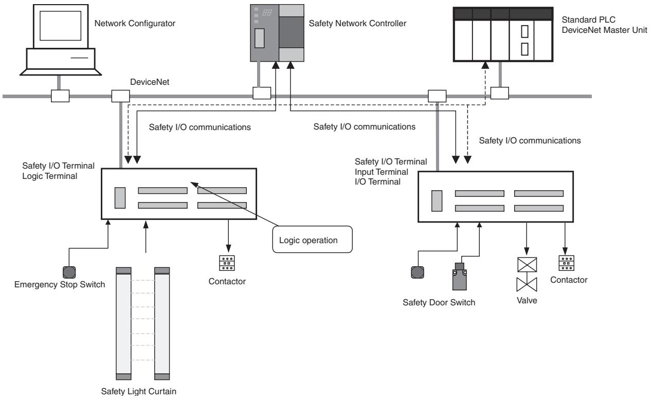
The DST1-series Safety I/O Terminals support the DeviceNet Safety protocol and provide various functions for the Safety System. The DST1-series Safety I/O Terminals allow the user to construct a safety control/network system that meets the requirements for Safety Integrity Level (SIL) 3 according to IEC 61508 (Functional Safety of Electrical/Electronic/ Programmable Electronic Safety-related Systems) and the requirements for Safety Category 4 according to EN 954-1.
The DST1-series Safety I/O Terminal's safety I/O data is transmitted through safety I/O communications conforming to the DeviceNet Safety Protocol, and the data processing is performed in conducted in the Safety Network Controller (NE1A-SCPU01).
Also, the status of the safety I/O data can be monitored in a standard PLC in an existing DeviceNet network using standard I/O communications or explicit message communications.
The DST1-XD0808SL-1 Logic Terminal has built-in logic functions. This enables direct control of local outputs from local inputs, allowing reaction time to be shortened.
flowchart
graph TD
    A["Network Configurator"] --> B["DeviceNet"]
    B --> C["Safety I/O communications"]
    C --> D["Safety I/O Terminal Logic Terminal"]
    D --> E["Contactor"]
    E --> F["Safety Light Curtain"]
    F --> G["Emergency Stop Switch"]
    G --> H["Safety Door Switch"]
    H --> I["Valve"]
    I --> J["Contactor"]
    J --> K["Safety I/O communications"]
    K --> L["Safety I/O Terminal Input Terminal I/O Terminal"]
    L --> M["Logic operation"]
    M --> N["Safety Network Controller"]
    N --> O["Standard PLC DeviceNet Master Unit"]
1-1-2 DST1-series Safety I/O Terminals Features
Safety Inputs
- Semiconductor output devices such as light curtains can be connected as well as contact output devices such as emergency stop switches.
- Faults in external wiring can be detected.
- Input delays (ON delays and OFF delays) can be set.
- Pairs of related local inputs can be set to Dual Channel Mode in order to be compliant with the Category 4 standards.
When Dual Channel Mode is set, the input data patterns and the time discrepancy between input signals can be evaluated.
Test Outputs
- 4 independent test outputs are available to use.
- A disconnected external indicator lamp can be detected. (Can be set for the T3 Terminal only.)
- Test outputs can be used as power supply terminals to devices such as sensors.
- Test outputs can be used as the standard output terminals for monitor outputs.
Safety Outputs
■ Semiconductor Outputs
- Pairs of related local outputs can be set to Dual Channel Mode in order to be compliant with the Category 4 standards.
When Dual Channel Mode is set, the output data patterns can be evaluated. - The rated output current is 0.5 A max. per output.
■ Relay Outputs
- Pairs of related output terminals can be set to Dual Channel Mode in order to be compliant with the Category 4 standards.
When Dual Channel Mode is set, the output data patterns can be evaluated. - The rated output current is 2 A max. per output.
- The safety relays can be replaced.
DeviceNet Safety Communications
As a Safety Slave, a DST1-series Safety I/O Terminal can perform safety I/O communications on up to four connections (or up to two connections for the DST1-XD0808SL-1).
DeviceNet Standard Communications
As a Standard Slave, the DST1-series Safety I/O Terminals can perform standard I/O communications with one Standard Master with up to two connections.
System Startup and Error Recovery Support
- Error information can be checked by using the error log function or the indicators on the front of the DST1-series Safety I/O Terminals.
- The DST1-series Safety I/O Terminal's safety I/O data and internal status information can be monitored from a Standard PLC by allocating the information in the standard Master. In the same way, the information can be monitored from a safety PLC by allocating the information in the Safety Master.
Access Control with a Password
The DST1-series Safety I/O Terminals configuration data is protected by a password.
I/O Connector Connection/Disconnection
- The I/O Connector can be connected and disconnected.
- The I/O Connector is structured to prevent incorrect connection.
Cage Clamp Wiring
Cables can be wired without terminal screws.
Maintenance Functions
The DST1-series Safety I/O Terminals are equipped with maintenance functions, such as a contact operation counter and cumulative ON time monitor.
Logic Functions (DST1-XD0808SL-1 Only)
- The DST1-XD0808SL-1 Logic Terminal is provided with basic logic parameters, such as AND and OR.
- This enables direct control of DST1-XD0808SL-1 local outputs from local inputs without involving NE1A safety logic.
1-2 Standard Models
As shown in the following tables, the DST1 Series consists of Input Terminals, I/O Terminals, and Logic Terminals.
1-2-1 Input Terminals and I/O Terminals
| Model | I/O capacity | |||
| Safety inputs | Test outputs | Safety outputs | ||
| Semiconductor outputs | Relay outputs | |||
| DST1-ID12SL-1 | 12 inputs | 4 outputs (See note.) | - | - |
| DST1-MD16SL-1 | 8 inputs | 4 outputs (See note.) | 8 outputs | - |
| DST1-MRD08SL-1 | 4 inputs | 4 outputs (See note.) | - | 4 outputs |
Note Each test output can be set to function as a test output or a standard output. Test outputs are used in combination with a safety input. Broken wires in an external indicator can be detected for terminal T3 only.
1-2-2 Logic Terminals
| Model | I/O capacity | |||
| Safety inputs | Test outputs | Safety outputs | ||
| Semiconductor outputs | Relay outputs | |||
| DST1-XD0808SL-1 | 8 inputs | 4 outputs (See note.) | 8 outputs | - |
Note (1) Each test output can be set to function as a test output or a standard output. Test outputs are used in combination with a safety input. Broken wires in an external indicator can be detected for terminal T3 only.
(2) Use Network Configurator version 2.0 or higher to set the DST1-XD0808SL-1.
1-3 Functions
1-3-1 Functions Supported by All DST1-series Terminals
Note Except for the DST1-MRD08SL-1.
| Function | Description | Reference | |
| Safety I/O | |||
| Safety inputs | The DST1-ID12SL-1 supports 12 safety inputs.The DST1-MD16SL-1 supports 8 safety inputs.The DST1-MRD08SL-1 supports 4 safety inputs.The DST1-XD0808SL-1 supports 8 safety inputs. | 1-4 Description of Safety FunctionsSECTION 5DST1 Series Specifications | |
| Input circuit diagnosis | Diagnoses internal circuits and external devices and wiring using test pulses. | ||
| Input delays (ON or OFF) | The input time constant can be set from 0 to 126 ms in units of 6 ms. This function can be used to reduce the effects of chattering and external noise. | ||
| Dual channel evaluation | Dual channel evaluation can be used to evaluate the discrepancy time between two associated local input data items or input signals. | ||
| Test outputs | Four independent test outputs are supported. Test outputs are used in combination with safety inputs. Depending on the settings, they can also be used as signal output terminals. | 1-4 Description of Safety FunctionsSECTION 5DST1 Series Specifications | |
| Broken wire detection (terminal T3 only) | Broken wires can be detected for terminal T3. | ||
| Overcurrent detection and protection | When an overcurrent is detected, the output is turned OFF to protect the circuit. | ||
| Safety outputs | The DST1-MD16SL-1 supports 8 safety outputs.The DST1-MRD08SL-1 supports 4 safety outputs.The DST1-XD0808SL-1 supports 8 safety outputs. | 1-4 Description of Safety FunctionsSECTION 5DST1 Series Specifications | |
| Output circuit diagnosis (See note.) | Diagnoses internal circuits and external devices and wiring according to test pulses. | ||
| Overcurrent detection and protection (See note.) | When an overcurrent is detected, the output is turned OFF to protect the circuit. | ||
| Dual channel evaluation | When an error occurs at one of two associated local outputs, the dual channel evaluation sets the two outputs to the safe state without relying on a user program. | ||
| DeviceNet Communications | |||
| Safety Slaves | DST1-series Terminals can be operated as DeviceNet Safety Slaves. Not only specified I/O areas, but also internal status information can be assigned in Safety Masters. | SECTION 3Configuration | |
| Standard Slaves | DST1-series Terminals can be operated as Standard Slaves. Not only specified I/O areas, but also internal status information can be assigned in Standard Masters. | SECTION 3Configuration | |
| Explicit message communications | Internal status information can be read by using a service for explicit messages. | Appendix 1:DeviceNet Explicit Messages | |
| Automatic baud rate detection | The baud rate is automatically set to the baud rate of the network. | - | |
| System Startup and Error Recovery Support | |||
| Error history | Internally saves information on errors that are detected. | 7-3 Error History | |
| Online monitoring | Internal status information and I/O data can be read using the Network Configurator. | Section 7 in DeviceNet Safety System Configuration Manual (Z905) | |
| Function | Description | Reference | |
| Other Functions | |||
| Configuration lock | After configuration data has been downloaded and verified, the configuration data that has been saved internally can be locked. | Section 3 in DeviceNet Safety System Configuration Manual (Z905) | |
| Reset | DST1-series Terminals can be reset using a service from the Network Configurator. | ||
| Password | A password can be set to prevent the DST1-series Terminal from being accessed unintentionally. | ||
1-3-2 Input Terminals and I/O Terminals
The following functions are provided by the DST1-ID12SL-1, DST1-MD16SL-1, and DST1-MRD08SL-1.
| Function | Description | Reference |
| Maintenance | ||
| Network power supply voltage monitor | The present, bottom, and peak values for the network power supply voltage can be recorded in the DST1-series Terminal. | Section 7 in DeviceNet Safety System Configuration Manual (Z905) |
| Unit conduction time monitor | The total ON time (unit: 0.1 h) of the internal circuit power can be calculated and recorded in the DST1-series Terminal. | |
| Unit name | The user can record a name or comment for each DST1-series Terminal, using up to 32 characters. | |
| I/O comments | The user can record a name or comment for each I/O terminal, using up to 32 characters. | |
| Last maintenance date | The date on which maintenance was last performed can be written in the DST1-series Terminal. | |
| I/O power status monitor | Can be used to check whether the I/O power is ON. | |
| Contact operation counters | Can be used to count the number of times each input or output contact changes from OFF to ON (maximum resolution of 50 Hz) and to record the total in the DST1-series Terminal. | |
| Total ON time monitor | Can be used to calculate the total ON time for each input or output contact (unit: s) and to record the total in the DST1-series Terminal. | |
| Operation time monitor | Can be used to measure the time from when an output contact turns OFF until an input contact turns OFF (unit: ms) and to record the time in the DST1-series Terminal. | |
1-3-3 Logic Terminals
These functions are provided by the DST1-XD0808SL-1.
| Function | Description | Reference |
| Logic Functions | ||
| Logic functions | The DST1-XD0808SL-1 provides basic logic parameters, such as AND and OR. This enables direct control of local outputs from local inputs, reducing reaction time. | 1-5 Logic Functions |
| Safety I/O | ||
| Output ON/OFF delays | The output time constant can be set from 0 to 300,000 ms, in increments of 100 ms. | 1-5 Logic Functions |
| Additional output setting | Any of the following outputs can be set: Same or inverse values for safety output terminal and another safety output, output indicating operating mode, output indicating normal status, and reset request outputs. | |
| Maintenance | ||
| Network power voltage monitor | The present, bottom, and peak values for the network power supply voltage can be recorded in the DST1-series Terminal. | Section 7 in DeviceNet Safety System Configuration Manual (Z905) |
| Unit conduction time monitor | The total ON time (unit: 0.1 h) of the internal circuit power can be calculated and recorded in the DST1-series Terminal. | |
| Unit name | The user can record a name or comment for each DST1-series Terminal, using up to 32 characters. | |
| I/O comments | The user can record a name or comment for each I/O terminal, using up to 32 characters. | |
| Last maintenance date | The date on which maintenance was last performed can be written in the DST1-series Terminal. | |
| I/O power status monitor | Can be used to check whether the I/O power is ON. | |
| Contact operation counters (See note.) | Can be used to count the number of times each input or output contact changes from OFF to ON (maximum resolution of 50 Hz) and to record the total in the DST1-series Terminal. | |
| Total ON time monitor (See note.) | Can be used to calculate the total ON time for each input or output contact (unit: s) and to record the total in the DST1-series Terminal. | |
Note Not including test output terminals.
1-4 Description of Safety Functions
1-4-1 DST1-series Safety I/O Terminals
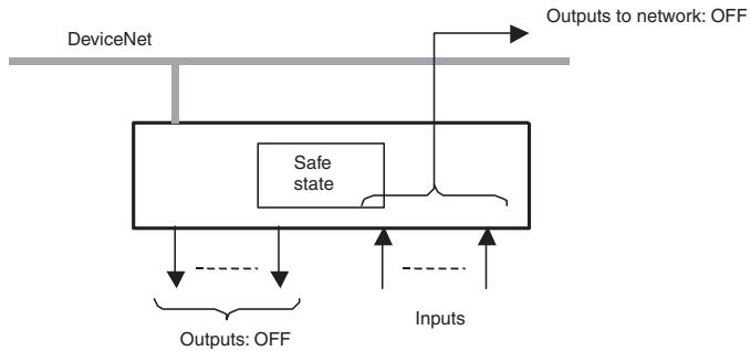
Safe State
The following status is treated as the safe state by the DST1-series Safety I/O Terminals.
- Safety outputs: OFF
- Output data to network: OFF
flowchart
graph TD
    A["DeviceNet"] --> B["Safe state"]
    B --> C["Outputs: OFF"]
    B --> D["Inputs"]
    E["Outputs to network: OFF"] --> B
Therefore, the DST1-series Safety I/O Terminals must be used for applications in which it enters into safe state when the safety outputs turn OFF and the output data to the network turns OFF.
Self-diagnosis Functions
Self-diagnosis is performed when the power is turned ON and periodically during operation. If an error occurs, it will be treated as a fatal error (the MS indicator will light in red), and the safety outputs and output data to the network will turn OFF.
Access Control by Password
After configuration data had been downloaded and verified, the configuration data within the DST1-series Safety I/O Terminals can be protected by a password.
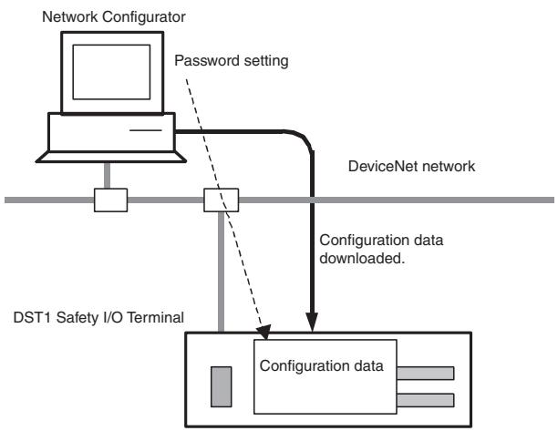
flowchart
graph TD
    A["Network Configurator"] -->|Password setting| B["DeviceNet network"]
    B --> C["Configuration data downloaded"]
    C --> D["DST1 Safety I/O Terminal"]
    D --> E["Configuration data"]
Note Refer to the System Configuration Manual (Cat. No. Z905) for password setting.
1-4-2 Safety Inputs
Safety Inputs with Test Pulses (Input Circuit Diagnosis)
A test output is used in combination with a safety input. Specify the corresponding test output terminal to use as the test source. The test output terminal is used as a power supply to connect an external input device to the safety input terminal.
Example: DST1-ID12S-1
Here, IN0 and T0 are used in combination,
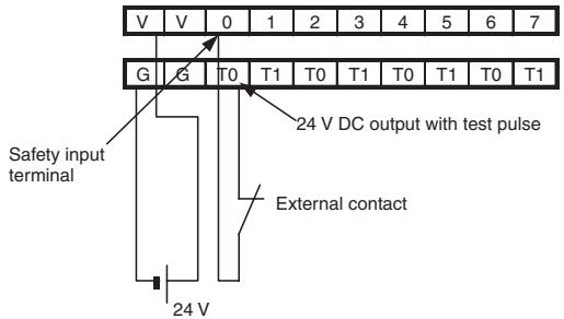
text_image
V V 0 1 2 3 4 5 6 7 G G T0 T1 T0 T1 T0 T1 T0 T1 24 V DC output with test pulse Safety input terminal External contact 24 VA test pulse is output from the test output terminal to diagnose the internal circuit when the external input contact turns ON. Using this function, short-circuits between input signal lines and the power supply (positive side), and short-circuits between input signal lines can be detected.
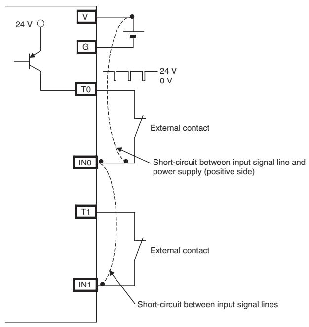
text_image
24 V V G T0 24 V 0 V External contact IN0 Short-circuit between input signal line and power supply (positive side) T1 External contact IN1 Short-circuit between input signal linesIf an error is detected, safety input data and individual safety input status will turn OFF.
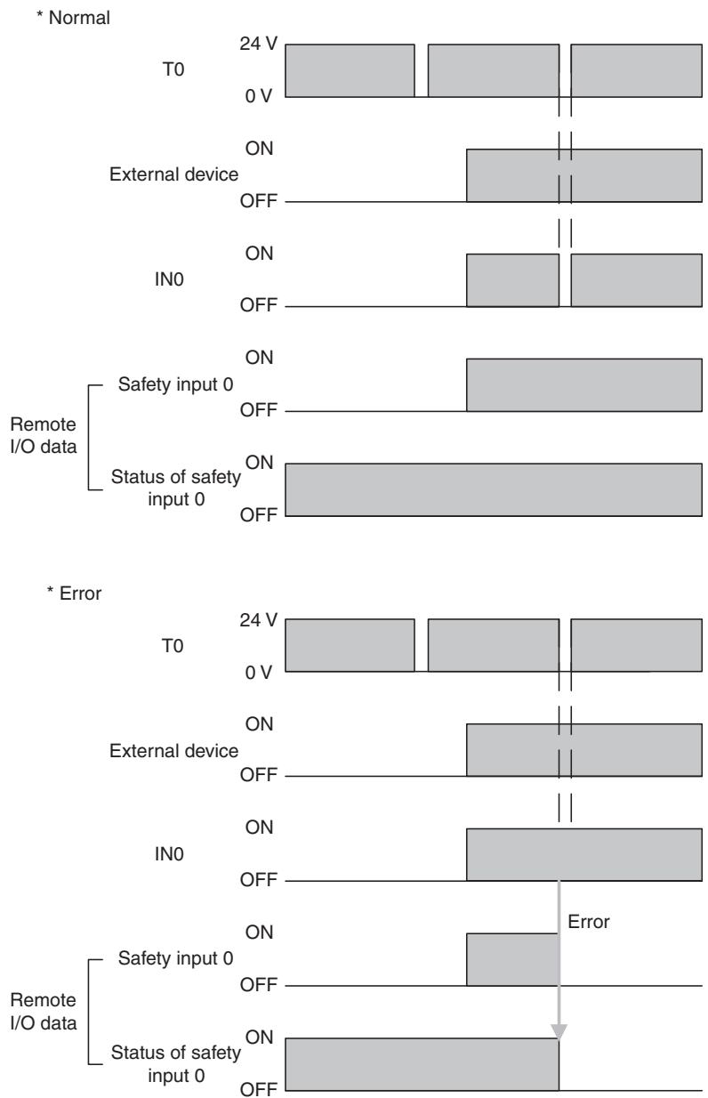
bar
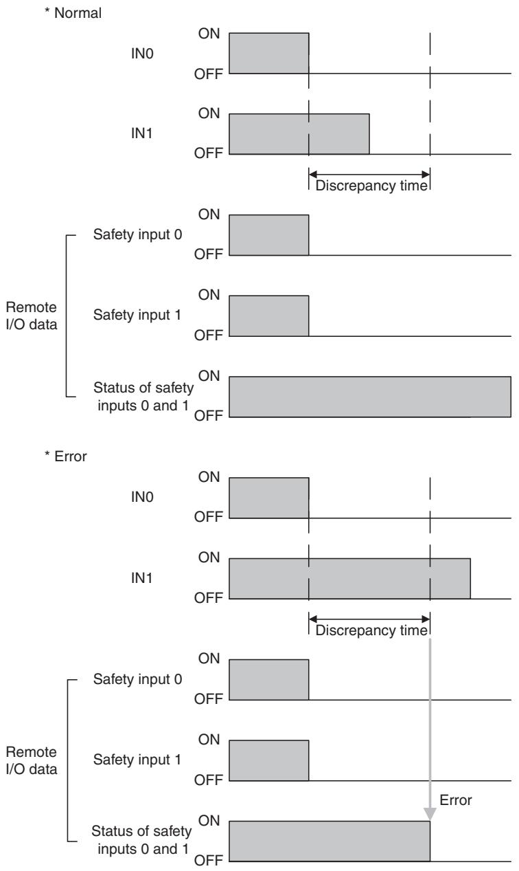
| Data Type | Condition | Voltage (V) | Current (V) | |-----------|-----------|-------------|-------------| | Normal | T0 | 24 | 0 | | Normal | External device | ON | OFF | | Normal | IN0 | ON | OFF | | Remote I/O data | Safety input 0 | ON | OFF | | Remote I/O data | Status of safety input 0 | ON | OFF | | Error | T0 | 24 | 0 | | Error | External device | ON | OFF | | Error | IN0 | ON | OFF | | Remote I/O data | Safety input 0 | ON | OFF | | Remote I/O data | Status of safety input 0 | ON | OFF |Setting Dual Channel Mode and Discrepancy Time
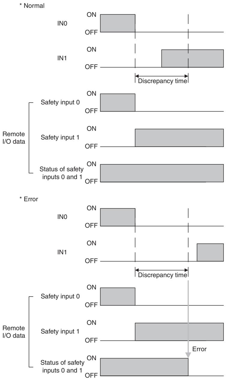
The consistency between signals on two channels can be evaluated. Either of the following settings can be selected. This function monitors the time during which there is a discrepancy in the logic between the two channels set as dual channels. If the length of the discrepancy exceeds the set discrepancy time (0 to 65,530 ms, in increments of 10 ms), the safety input data and the individual safety input status will turn OFF for both inputs.
IMPORTANT The dual channel function is used with 2 consecutive inputs that start from even input numbers: inputs 0 and 1, inputs 2 and 3, inputs 4 and 5, etc.
The following table shows the relation between terminal input and remote I/O data.
| Dual channel mode | Input terminals | Remote I/O data | Meaning of data | ||
| IN0 | IN1 | Safety input 0 | Safety input 1 | ||
| Dual Channel Equivalent | 0 | 0 | 0 | 0 | OFF |
| 0 | 1 | 0 | 0 | OFF | |
| 1 | 0 | 0 | 0 | OFF | |
| 1 | 1 | 1 | 1 | ON | |
| Dual Channel Complementary | 0 | 0 | 0 | 1 | OFF |
| 0 | 1 | 0 | 1 | OFF | |
| 1 | 0 | 1 | 0 | ON | |
| 1 | 1 | 0 | 1 | OFF | |
Dual Channels, Equivalent
The status is treated as normal when both channels are ON or OFF. If one channel is ON and the other channel is OFF, it will be treated as an error, and the safety input data and the individual safety input status will turn OFF for both inputs.
Dual Channels, Complementary
The status is treated as normal when one channel is ON and the other channel is OFF. When both channels are ON or both channels are OFF, it is treated as an error, and the safety input data and the individual safety input status will turn OFF for both inputs.
Error Recovery
All conditions below are necessary to recover from an error that has occurred in a safety input.
- The cause of the error must be removed.
- The error latch time must have passed.
- The input signal must return to an inactive state and there must be no error condition detected. (e.g., by pressing the emergency stop switch or opening a door)
Input Delays
ON Delay
An input signal is treated as being OFF during the ON delay setting time (0 to 126 ms, in increments of 6 ms) after the input contact's rising edge. The input will turn ON only if the input contact remains ON after the ON delay time has elapsed. This helps prevent chattering of the input contacts.

text_image
IN OFF Remote I/O data Safety input ON OFF ON delayOFF Delay
An input signal is treated as being ON during the OFF delay setting time (0 to 126 ms, in increments of 6 ms) after the input contact's falling edge. The input will turn OFF only if the input contact remains OFF after the OFF delay time has elapsed. This helps prevent chattering of the input contacts.
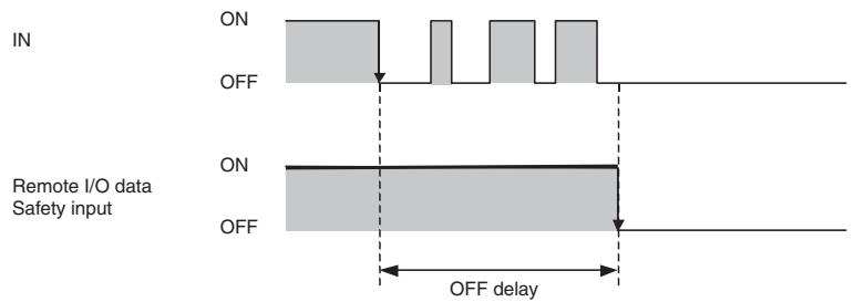
text_image
IN ON OFF Remote I/O data Safety input ON OFF OFF delay1-4-3 Safety Outputs
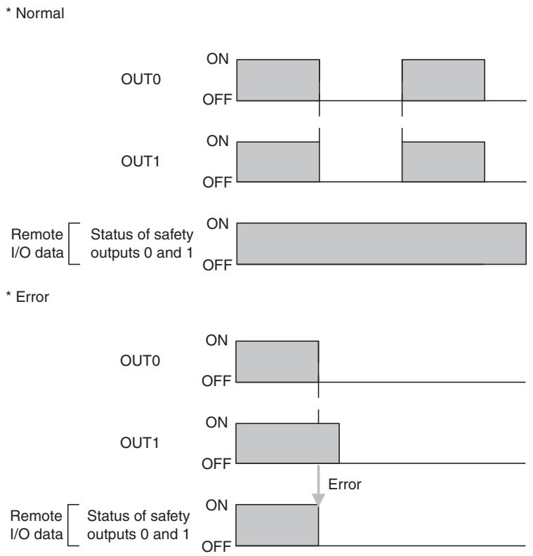
Safety Outputs with Test Pulses (Output Circuit Diagnosis)
When the output is ON, the test pulse is turned OFF for 470 s in a cycle of 648 ms. Using this function, short-circuits between output signal lines and the power supply (positive side) and short-circuits between output signal lines can be detected.
If an error is detected, the safety output data and the individual safety output status will turn OFF.
IMPORTANT To prevent the test pulse from causing the connected device to malfunction, pay careful attention to the input response time of the device.
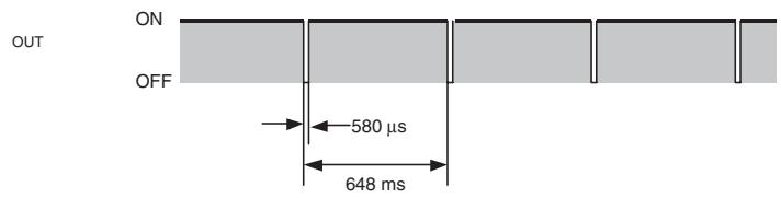
text_image
OUT ON OFF 580 µs 648 msDual Channel Setting
When both channels are normal, the outputs can be turned ON.
The status is treated as normal when both channels are normal. If an error is detected for one channel, the safety output data and the individual safety output status will turn OFF for both channels.
Error Recovery
All conditions below are necessary to recover from an error that has occurred in a
safety output.
- The cause of the error must be removed.
- Error latch time must have passed.
- The output signals to the output I/O tags from the user application that correspond to the safety output must go inactive.
1-4-4 I/O Status Data
In addition to I/O data, the DST1-series Safety I/O Terminals support status data to check the I/O circuits. The status data includes the following data, for which remote I/O communications can be performed.
- Normal Flags (ON when there is no faults in the internal circuit and the external wiring)
- An AND Flag of the Normal Flags
- Output monitors (the actual output ON/OFF status)
Normal Flags
Normal Flags indicates whether each safety input, safety output, or test output is normal (normal status: ON, error status: OFF).
Output Monitors
The outputs monitors indicated the actual ON/OFF status of the safety outputs.
1-5 Logic Functions
The DST1-XD0808SL-1 supports logic functions.
1-5-1 Overview
Safety logic control can be easily performed by setting a combination of I/O data from local I/O terminals and remote I/O data from a Standard Master or Safety Master with the logic operations supported by the DST1-XD0808SL-1. In addition, the safety status can be monitored from standard controls by using the safety output terminals as additional outputs and outputting data such as error information.
Note
(1) Refer to the NE0A Series Safety Network Controller Operation Manual (Cat. No. Z916) for details on functions and setting methods.
(2) Some NE0A-SCPU01 functions are not supported by the DST1-XD0808SL1. Refer to 1-5-2 Restrictions on the DST1-XD0808SL-1 for details
1-5-2 Restrictions on the DST1-XD0808SL-1
| NE0A Series Safety Network Controller Operation Manual | Restrictions on the DST1-XD0808SL-1 | |
| Section | Item | |
| 6-3-1 | Starting the Safety Wizard | Network settings cannot be made. |
| 6-3-4 | Setting Networks | Network settings cannot be made. |
| 6-4-1 | Safety Input Evaluation | Enable switches cannot be set. |
| User mode switches cannot be set. | ||
| Input ON-delay and OFF-delay times must be set from 0 to 126 ms (in 6-ms increments). | ||
| 6-4-2 | Input Condition Operations | Refer to 1-5-3 Parameters That Can Be Set for the input condition signals that can be set. |
| 6-4-3 | Reset Operation | Refer to 1-5-3 Parameters That Can Be Set for the reset condition signals that can be set. |
| 6-4-4 | Output Condition Operations | Refer to 1-5-3 Parameters That Can Be Set for the output condition signals that can be set. |
| 6-4-5 | Welding Check (EDM: External Device Monitoring) Operation | Refer to 1-5-3 Parameters That Can Be Set for the feedback signals that can be set. |
| 6-4-6 | Safety Output Evaluation | Refer to 1-5-3 Parameters That Can Be Set for the additional outputs that can be set. |
1-5-3 Parameters That Can Be Set
Data That Can Be Set for Input Condition Signals
| Name | Option | Setting range |
| Input condition signal | Remote I/O | Remote safety I/O data (received from Safety Master through the network) |
| Input 0 to Input 5 | Safety input terminals IN0 to IN5 |
The following data is used for remote I/O data. For details on remote I/O allocations, refer to 3-2-4 I/O Assembly Data.
| Bit 7 | Bit 6 | Bit 5 | Bit 4 | Bit 3 | Bit 2 | Bit 1 | Bit 0 |
| Reserved for system. | Input condition signal No. 5 | Input condition signal No. 4 (4/5) | Input condition signal No. 3 | Input condition signal No. 2 (2/3) | Input condition signal No. 1 | Input condition signal No. 0 (0/1) | |
Example 1: IN0 and IN1 Used in Single Channel Mode
IN0 input condition signal: Bit 0 input condition signal 0 (0/1) is used.
IN1 input condition signal: Bit 1 input condition signal 1 is used.
Example 2: IN0 and IN1 Used in Dual Channel Mode
IN0 input condition signal: Bit 0 input condition signal 0 (0/1) is used.
IN1 input condition signal: Not used.
Data That Can Be Set for Reset Signals
| Name | Option | Setting range |
| Reset signal | Remote I/O Low-High-Low | Remote safety I/O data (received from Safety Master or Standard Master through the network) used for a Low-high-Low reset. |
| Remote I/O Rising Edge | Remote safety I/O data (received from Safety Master or Standard Master through the network) used for a Rising Edge reset. | |
| IN6 Low-High-Low | The IN6 terminal is used for a Low-High-Low reset. | |
| IN6 Rising Edge | The IN6 terminal is used for a Rising Edge reset. | |
| IN7 Low-High-Low | The IN7 terminal is used for a Low-High-Low reset. | |
| IN7 Rising Edge | The IN7 terminal is used for a Rising Edge reset. |
The following data is used for remote I/O data. For details on remote I/O allocation, refer to 3-2-4 I/O Assembly Data.
| Bit 7 | Bit 6 | Bit 5 | Bit 4 | Bit 3 | Bit 2 | Bit 1 | Bit 0 |
| Reserved for system. | Reset signalNo.5 | Reset signalNo.4 (4/5) | Reset signalNo.3 | Reset signalNo.2 (2/3) | Reset signalNo.1 | Reset signalNo.0 (0/1) | |
Example 1: IN0 and IN1 Used in Single Channel Mode
IN0 reset signal: Bit 0 reset signal 0 (0/1) is used.
IN1 reset signal: Bit 1 reset signal 1 is used.
Example 2: IN0 and IN1 Used in Dual Channel Mode
IN0 reset signal: Bit 0 reset signal 0 (0/1) is used.
IN1 reset signal: Setting not required.
Data That Can Be Set for Safety Input Logic Result or Remote I/O ... —
| Name | Option | Setting range |
| Output condition signal | Remote I/O | Data received from Safety Master or Standard Master through the network |
| IN0 to IN5 | Safety input logic operation result |
The following data is used for remote I/O data. For details on remote I/O allocations, refer to 3-2-4 I/O Assembly Data.
| Bit 7 | Bit 6 | Bit 5 | Bit 4 | Bit 3 | Bit 2 | Bit 1 | Bit 0 |
| Safety output terminal 7, output condition signal 7 | Safety output terminal 6, output condition signal 6 (6/7) | Safety output terminal 5, output condition signal 5 | Safety output terminal 4, output condition signal 4 (4/5) | Safety output terminal 3, output condition signal 3 | Safety output terminal 2, output condition signal 2 (2/3) | Safety output terminal 1, output condition signal 1 | Safety output terminal 0, output condition signal 0 (0/1) |
Or
| Bit 7 | Bit 6 | Bit 5 | Bit 4 | Bit 3 | Bit 2 | Bit 1 | Bit 0 |
| Output condition signal 7 | Output condition signal 6 (6/7) | Output condition signal 5 | Output condition signal 4 (4/5) | Output condition signal 3 | Output condition signal 2 (2/3) | Output condition signal 1 | Output condition signal 0 (0/1) |
Example 1: Outputs 0 and 1 Used in Single Channel Mode
Output 0 output condition signal: Bit 0 output condition signal 0 (0/1) is used.
Output 1 output condition signal: Bit 1 output condition signal 1 is used.
Example 2: Outputs 0 and 1 Used in Dual Channel Mode
Output 0 output condition signal: Bit 0 output condition signal 0 (0/1) is used.
Output 1 output condition signal: Setting not required.
Data That Can Be Set for Feedback Signals

| Name | Option | Setting range |
| Feedback signal | IN4 | Use the IN4 terminal as the feedback input terminal. |
| IN5 | Use the IN5 terminal as the feedback input terminal. | |
| IN6 | Use the IN6 terminal as the feedback input terminal. | |
| IN7 | Use the IN7 terminal as the feedback input terminal. |
Data That Can Be Set for Additional Outputs
| Additional output data | Description | |
| S | Same value as safety output terminal | Outputs the same value as any safety output terminal. |
| S | Inverse value of safety output terminal | Outputs the inverse value of any safety output terminal. |
| Reset required indication | Outputs a 1-Hz pulsing signal to trigger a reset input. The signal is output when resetting is enabled for one or more terminals from among all the safety input terminals. | |
| RUN Status Flag | Outputs the operating mode.0: Not RUN mode1: RUN mode | |
| Normal Status Flag | Outputs the status.0: Error (See note.)1: Normal |
Note Turns OFF (0) when one of the errors shown in 7-3 Error History occurs.
IMPORTANT When additional output data is set, safety output terminals will reflect the output status even in Idle Mode.
Note (1) An additional output can be used only when the output terminals are set as a single channel.
(2) An ON delay or OFF delay can be set for safety output terminals even when an additional output is set.
SECTION 2
General Procedure
2-1 General Procedure.... 22
2-2 Installation.... 23
2-3 Connecting I/O Power and I/O Cable 24
2-4 Connecting the Communications Connector 26
2-5 Node Address 27
2-6 Configuration 27
2-1 General Procedure
The general procedure for using the DST1-series Safety I/O Terminals is given below.
Refer to the DeviceNet Operation Manual (Cat. No. W267) for the network structure and the topology.
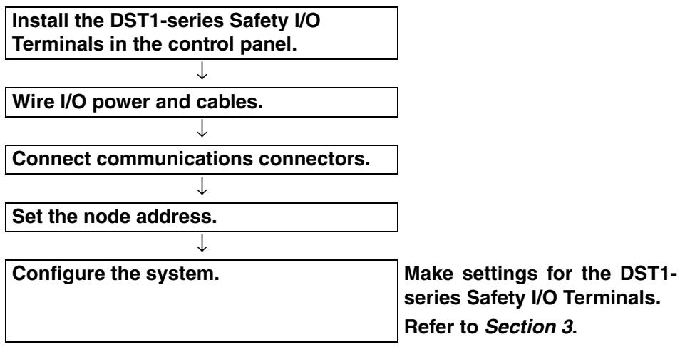
flowchart
graph TD
    A["Install the DST1-series Safety I/O Terminals in the control panel."] --> B["Wire I/O power and cables."]
    B --> C["Connect communications connectors."]
    C --> D["Set the node address."]
    D --> E["Configure the system."]
    E --> F["Make settings for the DST1-series Safety I/O Terminals. Refer to Section 3."]
The baud rate of the entire system is determined by the baud rate of the Master Unit. The baud rate does not need to be set for each DST1-series Safety I/O Terminals.
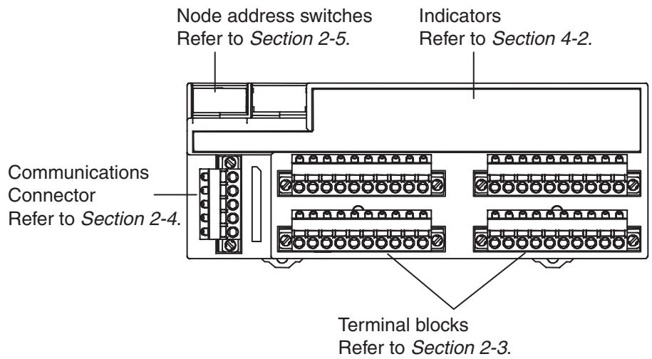
text_image
Node address switches Refer to Section 2-5. Indicators Refer to Section 4-2. Communications Connector Refer to Section 2-4. Terminal blocks Refer to Section 2-3.2-2 Installation
Use the DIN Track (35 mm wide) to install the DST1-series Safety I/O Terminals in the control panel.
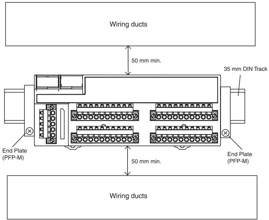
text_image
Wiring ducts 50 mm min. 35 mm DIN Track End Plate (PFP-M) End Plate (PFP-M) 50 mm min. Wiring ducts* Refer to the descriptions of individual DST1 models (Section 5) for dimensions.
IMPORTANT
- Use the DST1 in an environment that is within the general specifications.
- Use the DST1 in an enclosure rated IP54 (IEC 60529) or higher.
- Use DIN Track (35 mm wide) to mount the DST1 in the control panel.
- Always use an End Plate on each end of the DST1 to secure it.
- Allow a minimum of 50 mm above and below the DST1 for ventilation.
2-3 Connecting I/O Power and I/O Cable
The following table shows the applicable wires for the I/O connector (when using recommended post crimp terminals).
| Solid wire | 0.2 to 2.5 mm ^2 (AWG 24 to AWG 12) |
| Stranded wires | 0.34 to 1.5 mm ^2 (AWG 22 to AWG 16) |
* Refer to the descriptions of individual DST1 models (Section 5) for the terminal arrangement of the terminal block and wiring for external I/O.
Recommended Materials and Tools
Ferrules with Plastic Insulating Collars
Use the ferrules with insulating collars conforming to DIN 46228-4. Ferrules with similar appearance but not conforming to the standard may not match the terminal blocks of the DST1-series Safety I/O Terminals. (The wire dimensions shown below are rough dimensions. Confirm before application.)
Note
(1) If the terminal block is wired with ferrules, firmly insert them all the way in.
(2) When using 2-wire ferrules, the power lines must be of the same diameter.
(3) When using 2-wire ferrules, the metal part of the ferrule must be inserted straight into the terminal block.
Reference Specifications (Product Specifications from Phoenix Contact)
| Model of ferrule | Wire dimensions | Ferrule specifications | |||||||
| Cross-sectional area of conductor (mm2) | AWG | Removed length of insulation (mm) | Overall length L1 (mm) | Length of metal part L2 (mm) | Inner diameter of conductor D1 (mm) | Inner diameter of insulation cover D2 (mm) | Dimensions | ||
| For one wire | AI 0,34-8TQ | 0.34 | 22 | 10 | 12.5 | 8 | 0.8 | 2.0 | *1 |
| AI 0,5-10WH | 0.5 | 20 | 10 | 16 | 10 | 1.1 | 2.5 | ||
| AI 0,75-10GY | 0.75 | 18 | 10 | 16 | 10 | 1.3 | 2.8 | ||
| AI 1-10RD | 1.0 | 18 | 10 | 16 | 10 | 1.5 | 3.0 | ||
| AI 1,5-10BK | 1.5 | 16 | 10 | 18 | 10 | 1.8 | 3.4 | ||
| For two wires | AI-TWIN2 x 0,75-10GY | 2 x 0.75 | - | 10 | 17 | 10 | 1.8 | 2.8/5.0 | *2 |
| AI-TWIN2 x 1-10RD | 2 x 1 | - | 10 | 17 | 10 | 2.05 | 3.4/5.4 | ||

text_image
* 1 For One Wire Insulating collar L1 L2 Dia. D2 Dia. D1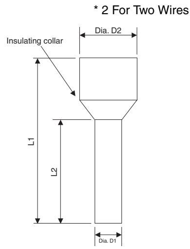
text_image
* 2 For Two Wires Insulating collar L1 L2 Dia. D2 Dia. D1Crimping Tool for Ferrules
| Manufacturer | Model |
| Phoenix Contact | CRIMPFOX UD6or CRIMPFOX ZA3 |
IMPORTANT
- I/O connectors are detachable. Tighten the screws on the I/O connector to 0.25 to 0.3 N·m.
- Separate I/O signal cables from high-voltage lines and power lines.
- I/O signal cables must be no longer than 30 m.
- Do not apply power to safety output terminals or test output terminals. Doing so may cause burning or other damage to the product.
- Do not remove the label from the DST1 before wiring.
- Always remove the label after completing wiring to ensure proper heat dispersion.
2-4 Connecting the Communications Connector
Colored stickers are provided on the communications connector that match the colors of the lines to be inserted. Check that the colors of the lines and stickers match when wiring the connectors. The colors are as follows:
| Color | Signal |
| Red | Power cable positive side (V+) |
| White | High side of communications data (CAN_H) |
| - | Shield |
| Blue | Low side of communications data (CAN_L) |
| Black | Power cable negative side (V-) |
Refer to the DeviceNet Operation Manual (Cat. No. W267) for details on communications specifications and wiring.
IMPORTANT
- When connecting the communications connector to the DST1, tighten the screws on the communications connector to 0.25 to 0.3 N·m.
- OMRON's S8□□Power Supplies are recommended for communications power.
Note
- The internal power for the DST1-series Safety I/O Terminals is supplied from the communications power supply (V+, V−).
2-5 Node Address
Set the node address using the two rotary switches on the front panel of the DST1-series Safety I/O Terminals. The default setting is 63. Set the tens digit of the node address (decimal) using the left rotary switch and set the ones digit using the right rotary switch. A value between 00 and 63 can be set.
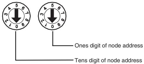
text_image
3 5 6 2 1 0 8 One digit of node address Tens digit of node addressIf a node address between 64 and 99 is set, the node address can be set from the Network Configurator.
IMPORTANT
- The node address must be set while the communications power supply is turned OFF.
- Do not change the rotary switches while the power is ON. The DST1-series Safety I/O Terminals will detect this as a change in the configuration and will switch to fault state.
- Use a small flat-blade screwdriver to set the rotary switches, being careful not to scratch them.
2-6 Configuration
Configure the DST1-series Safety I/O Terminals using the Network Configurator. Refer to Section 3 Configuration for details on settings. Refer to the System Configuration Manual (Cat. No. Z905) for Network Configurator operating procedures.
SECTION 3 Configuration
3-1 Editing Device Parameters 30
3-1-1 Parameter Group.... 30
3-1-2 General Parameters.... 31
3-1-3 Safety Input Parameters 32
3-1-4 Test Output Parameters.... 33
3-1-5 Safety Output Parameters 34
3-1-6 Operation Time Parameters 34
3-1-7 Safety Input Logic Parameter Groups (Safety Input Logic).... 35
3-1-8 Safety Output Logic Parameter Groups (Safety Output Logic).... 36
3-2 Remote I/O Allocations 37
3-2-1 I/O Allocations 37
3-2-2 I/O Data 37
3-2-3 I/O Data Supported by Each Model 38
3-2-4 I/O Assembly Data 43
3-2-5 Changing Default Standard I/O Assembly Data (DST1-XD0808SL-1 Only) 50
3-1 Editing Device Parameters
3-1-1 Parameter Group
The DST1-series Safety I/O Terminals have five parameter groups: General Parameters, Safety Input Parameters, Test Output Parameters, Safety Output Parameters, and Operating Time Parameters.
The settings in each parameter group are listed in the following tables. All parameters are set using the Network Configurator.
Note Parameters directly related to safety are marked with (s) in the left column.
3-1-2 General Parameters
| Parameter name | Value | Description | Default | |
| S | Safety Output Error Latch Time | 0 to 65,530 ms (in increments of 10 ms) | This parameter is common to all the safety outputs. It sets the time to latch the error state when an error occurs in these outputs. Even when the cause of the error has been removed, the error state will remain latched for the time set here. | 1,000 ms |
| S | Safety Input Error Latch Time | 0 to 65,530 ms (in increments of 10 ms) | This parameter is common to all safety inputs and test outputs. It sets the time to latch the error state when an error occurs in these inputs/outputs. Even when the cause of the error has been removed, the error state will remain latched for the time set here. | 1,000 ms |
| --- | Test Output Idle State | Clear OFF | This parameter is common to all test outputs for which the Test Output Channel Mode is set to Standard Output. It sets the output state of the test output when idle data is received. | Clear OFF |
| Keep output data | ||||
| --- | Unit Name | 32 characters max. | This parameter sets a user-chosen name for the DST1-series Safety I/O Terminals. The set name is saved in the DST1-series Safety I/O Terminals and displayed in the network configuration. | None |
| --- | Threshold Network Power Voltage | 8.0 to 30.0 V | This parameter sets the threshold of the network power voltage. When the voltage falls below the set threshold voltage, the corresponding bit in general status turns ON. | 11 V |
| --- | Threshold Run Hours | 0 to 429,496,729 hours | This parameter sets the threshold for unit operating hours. When the operating hours exceeds the set threshold, the corresponding bit in general status will turn ON. | 0 hours |
| --- | Last Maintenance date | 1972/01/01 to 2038/01/19 | This parameter saves the maintenance date in the DST1-series Safety I/O Terminals. | 1972/01/01 |
| S | Execution Mode (DST1-XD0808SL-1 only) | After Establishing Safety I/O Connection | Starts in Idle Mode after the configuration has been completed. Goes into RUN Mode when safety I/O communications are started. | After Establishing Safety I/O Connection |
| Auto Execution | Selecting this mode and executing the following operations causes startup in RUN Mode from that point onwards. • Locking the configuration • Turning OFF the power after changing to RUN Mode Safety I/O communications are not possible in this mode. | |||
IMPORTANT If the power is turned OFF in Idle Mode, the next operation will not start in RUN Mode even if Auto Execution is set as the execution mode and the configuration is locked. The power must be turned OFF in RUN Mode.
IMPORTANT Safety I/O communications cannot be used when Auto Execution is set as the execution mode. To use safety I/O communications, set After Establishing Safety I/O Connection as the execution mode.
3-1-3 Safety Input Parameters
| Parameter name | Value | Description | Default | |
| S | Off On Delay | 0 to 126 ms(in increments of 6 ms) | Sets the OFF/ON delay time. | 0 ms |
| S | Off On Delay | 0 to 126 ms(in increments of 6 ms) | Sets the ON/OFF delay time. | 0 ms |
| S | Safety Input Channel Mode | Not Used | The safety input is not used.(External input device not connected.) | Not Used |
| Test Pulse from Test Output | Specifies connecting a device with a contact output in combination with a test output. When this mode is selected, select the test output to use for the test source and then set the test output mode to Pulse Test Output. When these settings are made, contact between the input signal line and the power supply (plus) and short circuits with other input signal lines can be detected. | |||
| Used as Safety Input | Specifies connecting a safety device with a semiconductor output, such as a light curtain. | |||
| Used as Standard Input | Specifies connecting a standard device (i.e., a non-safety device). | |||
| S | Safety Input Test Source | Not used | If the channel mode of a safety input is set to Test Pulse from Test Out, the test output is selected for use in combination with the safety input. Set the channel mode of the test output selected here to Pulse Test Output. | Not Used |
| Test Output 0 | ||||
| Test Output 1 | ||||
| Test Output 2 | ||||
| Test Output 3 | ||||
| S | Dual Channel Safety Input Mode | Single Channel | Specifies using Single Channel Mode. If Single Channel is selected, the safety input that would be paired for the dual channel parameter will also be set to Single Channel Mode. | Dual Channel Equivalent |
| Dual Channel Equivalent | Specifies using the Dual Channel Equivalent Mode with a paired safety input. | |||
| Dual Channel Complementary | Specifies using Dual Channel Complementary Mode with a paired safety input. | |||
| S | Dual Channel Safety Input Discrepancy Time | 0 to 65,530 ms(in increments of 10 ms) | Sets the time to monitor the logic discrepancy in the dual channel input logic. Input logic, however, will not be evaluated when this value is set to 0 ms. | 0 ms |
| --- | I/O Comment | 32 characters max. | Sets an I/O comment for the safety input.The I/O comment set here is used as the I/O tag in the NE1A-series Logic Editor. | None |
| --- | Maintenance Counter Mode Choice | Time | Sets the operating mode for the maintenance counter. | Time |
| Count | ||||
| --- | Threshold Maintenance Counter | 0 to 4,294,967,295 | Sets the threshold value for the maintenance counter. | 0 |
Note When the Safety Input Channel Mode is set to Test Pulse from Test Out, specify the test output to use for the test source and set the Test Output Mode of the test output to Pulse Test Output.
3-1-4 Test Output Parameters
| Parameter name | Value | Description | Default | |
| S | Test Output Mode | Not Used | The corresponding test output is not used. | Not Used |
| Standard Output | Specifies connecting to the input for a muting lamp or PLC. Used as a monitor output. | |||
| Pulse Test Output | Specifies connecting a device with a contact output in combination with the safety input. | |||
| Power Supply Output | Specifies connecting to the power supply terminal of a safety sensor. The voltage supplied from the test output to the I/O power supply (V, G) is output. | |||
| Muting Lamp Output(Terminal T3 only) | Specifies a muting lamp output.When the output is ON, disconnection of the muting lamp can be detected. | |||
| --- | Fault Action | Clear OFF | Sets the output state of the test output when a communications error occurs.This parameter is enabled when the Test Output Mode is set to Standard Output or Muting Lamp Output. | Clear OFF |
| Hold Last Data | ||||
| --- | I/O Comment | 32 characters max. | Sets an I/O comment for the test output. The I/O comment set here is used as the I/O tag in the NE1A-series Logic Editor. | None |
| --- | Maintenance Counter Mode Choice (Cannot be set for the DST1-XD0808SL-1.) | Time | Sets the operating mode for the maintenance counter. | Time |
| Count | ||||
| --- | Threshold Maintenance Counter Monitor Value (Cannot be set for the DST1-XD0808SL-1.) | 0 to 4,294,967,295 | Sets the threshold value for the maintenance counter. | 0 |
Note With the DST1-XD0808SL-1, the contact operation counter and cumulative ON time monitor functions cannot be used for test output terminals.
3-1-5 Safety Output Parameters
| Parameter name | Value | Description | Default | |
| S | Safety Output Channel Mode | Not Used | The safety output is not used. (External output device not connected.) | Not Used |
| Safety (Can be set for the DST1-XD0808SL-1 only.) | Specifies not outputting the test pulse when the output is ON. Contact between the output signal line and the power supply (positive) when the output is OFF and ground faults can be detected. | |||
| Safety Pulse Test (Can be set for the DST1-XD0808SL-1 only.) | Outputs the test pulse when the output is ON. Contact between the output signal line and the power supply, and short circuits with other output signal lines can be detected. | |||
| Used (Can be set for the DST1-MRD0808SL-1 only.) | Uses safety output terminals. | |||
| S | Dual Channel Safety Output Mode | Single Channel | Specifies using Single Channel Mode. When Single Channel is set, the safety output that would be paired for the dual channel parameter is also set to Single Channel Mode. | Dual Channel |
| Dual Channel | Specifies using Dual Channel Mode. When both of the safety outputs to be paired are normal, the outputs can be turned ON. | |||
| --- | I/O Comment | 32 characters max. | Sets an I/O comment for the safety output. The I/O comment set here is used as the I/O tag in the NE1A-series Logic Editor. | None |
| --- | Maintenance Counter Mode Choice | Time | Sets the operating mode for the maintenance counter. | Time |
| Count | ||||
| --- | Threshold Maintenance Counter | 0 to 4,294,967,295 | Sets the threshold value for the maintenance counter. | 0 |
3-1-6 Operation Time Parameters
| Parameter name | Value | Description | Default | |
| --- | Equipment Name (Can-not be set for the DST1-XD0808SL-1.) | 32 characters max. | Sets a comment for the operation time to monitor. | None |
| --- | Threshold Operation Time (Cannot be set for the DST1-XD0808SL-1.) | 0 to 65,535 ms(in increments of 1 ms) | Sets the threshold value for the operation time. | 0 ms |
Note The operation time monitor function cannot be used with the DST1-XD0808SL-1.
3-1-7 Safety Input Logic Parameter Groups (Safety Input Logic)
Safety input parameter groups can be set only for the DST1-XD0808SL-1. Set these parameters using the Safety Logic Wizard.
| Parameter name | Value | Description | Default | |
| S | Input Condition | Not Used | Does not perform logic operations with safety input terminals. | Not Used |
| Logic operations for other safety input terminals and remote I/O signals | Performs logic operations with safety input terminals. The values for the OR operation are set from AND or OR operations of signals received from other safety input terminals and remote I/O (from the Master). | |||
| S | Reset Condition | Auto Reset | Sets reset conditions and reset input terminals. The reset conditions are selected from Auto Reset, L-H-L (Low - High - Low), and Rising Edge. Values used for reset inputs are selected from signals received from IN6, IN7, and remote I/O (from the Master). | Auto Reset |
| IN6 L-H-L | ||||
| IN6 Rising Edge | ||||
| IN7 L-H-L | ||||
| IN7 Rising Edge | ||||
| NW L-H-L | ||||
| NW Rising Edge | ||||
| --- | Safety Input Logic Comment | 48 single-byte characters max. | Sets the I/O comment for the results of safety input logic operations (input condition operations and reset operations). The I/O comment set here is used as the I/O tag by the NE1A-series Logic Editor. | None |
Note Safety input parameter groups can be set only for DST1-XD0808SL-1 safety inputs IN0 to IN5. For details on DST1-XD0808SL-1 logic functions, refer to 1-5 Logic Functions.
3-1-8 Safety Output Logic Parameter Groups (Safety Output Logic)
Safety output parameter groups can only be set for the DST1-XD0808SL-1. Set these parameters using the Safety Logic Wizard.
| Parameter name | Value | Description | Default | |
| S | Output Condition | Output from network | Uses a safety output terminal as a network output. The value (safety output) received from the net-work is directly output. | Output from net-work |
| Logic operations for safety input logic operation results and remote I/O signals (output from internal logic) | Uses the output as a safety output terminal logic output. The logic operation result is output. Set logic operations for safety input logic operation results and remote I/O (received from the Master). | |||
| Additional output | Uses a safety output terminal as an additional output terminal. Select the data to be output as the additional output data. | |||
| S | Welding Check (EDM) Feedback | Not Used | EDM feedback is not used. | Not Used |
| IN4 | EDM feedback is used. Select the terminals for connecting feedback signals from external devices. | |||
| IN5 | ||||
| IN6 | ||||
| IN7 | ||||
| S | Additional Output Data | Not Used | This setting is enabled when the safety output condition is set to additional output. | Not Used |
| OUT0 | Outputs the same value as OUT0. | |||
| OUT0 (NOT) | Outputs the inverse value of OUT0. | |||
| OUT2 | Outputs the same value as OUT2. | |||
| OUT2 (NOT) | Outputs the inverse value of OUT2. | |||
| OUT4 | Outputs the same value as OUT4. | |||
| OUT4 (NOT) | Outputs the inverse value of OUT4. | |||
| OUT6 | Outputs the same value as OUT6. | |||
| OUT6 (NOT) | Outputs the inverse value of OUT6. | |||
| Reset Required Indication | Outputs a 1-Hz pulsing signal to trigger a reset input. | |||
| RUN Status Flag | Outputs the operating mode.0: Not RUN mode1: RUN mode | |||
| Normal Status Flag | Outputs the status.0: Error (See note 1.)1: Normal | |||
| S | Off On Delay | 0 to 300,000 ms (Unit: 100 ms) | Sets the ON delay time. | 0 ms |
| S | On Off Delay | 0 to 300,000 ms (Unit: 100 ms) | Sets the OFF delay time. | 0 ms |
Note
(1) Turns OFF (0) when one of the errors shown in 7-3 Error History occurs.
(2) Safety output parameter groups can be set only for DST1-XD0808SL-1 safety outputs OUT0 to OUT7. For details on DST1-XD0808SL-1 logic functions, refer to 1-5 Logic Functions.
3-2 Remote I/O Allocations
3-2-1 I/O Allocations
The DST1-series Safety I/O Terminals internally store I/O data. Connection paths can be set using the Network Configurator to allocate I/O data for the Master Unit. Be sure to set the required connection paths.
3-2-2 I/O Data
The DST1-series Safety I/O Terminals store the following data.
- SAFE: The Controller can use this information in safety-related functions.
| Data | Description | |
| Input data | Safety Input DataSAFE | Indicates the ON/OFF status of each input terminal.• ON: 1• OFF: 0 |
| Combined Safety Input Status | An AND of the status of all input terminals.• All terminals are normal: 1• An error has been detected in one or more input terminals: 0 | |
| Individual Safety Input Status | Indicates the status of each input terminal.• Normal: 1• Error: 0 | |
| Combined Safety Output Status | An AND of the status of all output terminals.• All terminals are normal: 1• An error has been detected in one or more output terminals: 0 | |
| Individual Safety Output Status | Indicates the status of each output terminal.• Normal: 1• Error: 0 | |
| Muting Lamp Status | Indicates the status when terminal T3 is configured as the muting lamp output.• Normal: 1• Error: 0 | |
| Safety Output Monitor | Monitors the outputs of the safety output terminals.• ON: 1• OFF: 0 | |
| Individual Test Output Status | Indicates the status of each of the test output terminals.• Normal: 1• Error: 0 | |
| Safety Input Logic Result (DST1-XD0808SL-1 only.)SAFE | Operation result for safety input logic operation• ON: 1• OFF: 0 | |
| Reset Required Indication Signal (DST1-XD0808SL-1 only.) | Reset required indication signal pulse for reset of logic operations. | |
Note For information on errors, refer to 7-2 Troubleshooting.
| Data | Description | |||
| Input data | General Status Data | DST1-ID12SL-1DST1-MD16SL-1DST1-MRD08SL-1 | DST1-XD0808SL-1 | |
| Bit 0 | Safety Input Power Status Flag0: Input power supply ON1: Input power supply OFF | |||
| Bit 1 | Safety Output Power Status Flag0: Output power supply ON1: Output power supply OFF | |||
| Bit 2 | Network Power Voltage Drop Flag0: Normal (higher than set monitor value)1: Error (same as or lower than set monitor value) | |||
| Bit 3 | Unit Maintenance Flag0: Within range (lower than set monitor value)1: Over range (same as or higher than set monitor value) | |||
| Bit 4 | Reserved | Operating Mode Flag0: Not RUN mode1: RUN mode | ||
| Bit 5 | Combined I/O Port Status Flag0: Normal (all I/O points normal)1: Error (one or more I/O point error) | |||
| Bit 6 | Operation Time Exceeded Flag0: Within range (all I/O values are lower than set monitor value)1: Over range (one or more value is same as or higher than set value) | Status Flag0: Error (See note.)1: Normal | ||
| Bit 7 | Connected Component Maintenance Flag0: Within range (all I/O points are lower than set monitor value)1: Over range (one or more I/O point is same as or higher than set monitor value) | |||
| Output data | Safety Output DataSAFE | Controls the safety output terminal.• ON: 1• OFF: 0 | ||
| Safety Output Data and Output Condition Signal (DST1-XD0808SL-1 only)SAFE | When the safety output terminal is set toOutput from network:Safety output terminal ON/OFF status• ON: 1• OFF: 0When the safety output terminal is set toOutput from internal logic:Remote I/O signal for output condition operation• ON: 1• OFF: 0 | |||
| Output Condition Signal (DST1-XD0808SL-1 only) | Remote I/O signal for output condition operationWhen the safety output terminal is set toOutput from internal logic:• ON: 1• OFF: 0 | |||
| Standard Output Data | Controls the test output when test output mode is set to a standard output.• ON: 1• OFF: 0 | |||
| Input Condition Signal (DST1-XD0808SL-1 only)SAFE | Input condition signal for safety inputs. Used for input condition operations.• ON: 1• OFF: 0 | |||
| Reset Signal (DST1-XD0808SL-1 only) | Reset signal for safety inputs. Used for reset operations.• ON (High): 1• OFF (Low): 0 | |||
Note Turns OFF when one of the errors shown in 7-3 Error History occurs.
3-2-3 I/O Data Supported by Each Model
The following tables show the I/O data supported by each model of the DST1-series Safety I/O Terminals.
Refer to 3-2-4 I/O Assembly Data for data arrangements.
From among the I/O data, safety connections for up to four items, including one output, can be allocated for the Master Unit and standard connections for up to two items can be allocated for the Master Unit.
IMPORTANT Communications with up to 15 Safety Controllers for each connection can be performed using multi-cast connection. If four connections are used, however, only a maximum of 30 Safety Controllers total can communicate with the DST1-series Safety I/O Terminals. Up to two safety connections can be used with the DST1-XD0808SL-1.
DST1-ID12SL-1
The default values for the I/O assembly data are as follows:
Safety connections:
| Default (Assembly instance number) | |
| IN | Safety input assembly 1 (Instance No. 20C) |
| OUT | None |
Standard Connections: The default values for each type of connection are given below.
| Connection | Default (assembly instance number) | |
| Poll | IN | Safety input assembly 6 (No. 312) |
| OUT | Standard output assembly (No. 21) | |
| Bit strobe | IN | Safety input assembly 6 (No. 312) |
| OUT | None | |
| COS | IN | Test out status with General status assembly (No. 340) |
| OUT | None | |
| Cyclic | IN | Test out status with General status assembly (No. 340) |
| OUT | None | |
The following I/O data can be selected from the Network Configurator.
| Safety connection | Standard connection | Network Configurator setting | Assembly Instance No. | I/O size (bytes) | Inputs | Outputs | |||||||||
| Safety Input Data | Combined Safety Input Status | Individual Safety Input Status | Combined Safety Output Status | Individual Safety Output Status | Muting Lamp Status | Safety Output Monitors | Individual Test Output Status | General Status | Safety Output Data | Standard Output Data | |||||
| √ | √ | Safety input assembly 1 | 20C | Input 2 | √ | ||||||||||
| √ | √ | Safety input assembly 2 | 224 | Input 2 | √ | √ | |||||||||
| √ | √ | Safety input assembly 3 | 22C | Input 3 | √ | √ | |||||||||
| √ | √ | Safety input assembly 4 | 310 | Input 2 | √ | √ | √ | ||||||||
| √ | √ | Safety input assembly 5 | 311 | Input 4 | √ | √ | √ | ||||||||
| √ | √ | Safety input assembly 6 | 312 | Input 4 | √ | √ | √ | √ | |||||||
| √ | √ | Standard output assembly | 21 | Output 1 | √ | ||||||||||
| √ | General status assembly | 300 | Input 1 | √ | |||||||||||
| √ | Test output status with general status assembly | 340 | Input 2 | √ | √ | ||||||||||
DST1-MD16SL-1
The default values for the I/O assembly data are as follows:
Safety connections:
| Default (Assembly instance number) | |
| IN | Safety input assembly 1 (Instance No. 204) |
| OUT | Safety output assembly 1 (Instance No. 234) |
Standard connection: The default values for each type of connection are given below.
| Connection | Default (assembly instance number) | |
| Poll | IN | Safety input assembly 5 (No.323) |
| OUT | Standard output assembly (No.21) | |
| Bit strobe | IN | Safety input assembly 5 (No.323) |
| OUT | None | |
| COS | IN | Output Monitor/Test Out status with General status assembly (No.341) |
| OUT | None | |
| Cyclic | IN | Output Monitor/Test Out status with General status assembly (No.341) |
| OUT | None | |
The following I/O data can be selected from the Network Configurator.
| Safety connection | Standard connection | Network Configurator setting | Assembly Instance No. | I/O size (bytes) | Inputs | Outputs | |||||||||
| Safety Input Data | Combined Safety Input Status | Individual Safety Input Status | Combined Safety Output Status | Individual Safety Output Status | Muting Lamp Status | Safety Output Monitors | Individual Test Output Status | General Status | Safety Output Data | Standard Output Data | |||||
| √ | √ | Safety input assembly 1 | 204 | Input 1 | √ | ||||||||||
| √ | √ | Safety input assembly 2 | 320 | Input 2 | √ | √ | √ | √ | |||||||
| √ | √ | Safety input assembly 3 | 321 | Input 4 | √ | √ | √ | √ | |||||||
| √ | √ | Safety input assembly 4 | 322 | Input 5 | √ | √ | √ | √ | √ | ||||||
| √ | √ | Safety input assembly 5 | 323 | Input 5 | √ | √ | √ | √ | √ | √ | |||||
| √ | √ | Standard output assembly | 21 | Output 1 | √ | ||||||||||
| √ | Safety output assembly 1 | 234 | Output 1 | √ | |||||||||||
| √ | Safety output assembly 2 | 351 | Output 2 | √ | √ | ||||||||||
| √ | General status assembly | 300 | Input 1 | √ | |||||||||||
| √ | Output monitor/test output status with general status assembly | 341 | Input 3 | √ | √ | √ | |||||||||
DST1-MRD08SL-1
The default values for the I/O assembly data are as follows:
Safety connections:
| Default (Assembly instance number) | |
| IN | Safety input assembly 1 (Instance No. 203) |
| OUT | Safety output assembly 1 (Instance No. 233) |
Standard connection: The default values for each type of connection are given below.
| Connection | Default (assembly instance number) | |
| Poll | IN | Safety input assembly 5 (No.333) |
| OUT | Standard output assembly (No.21) | |
| Bit strobe | IN | Safety input assembly 5 (No.333) |
| OUT | None | |
| COS | IN | Output Monitor/Test Out status with General status assembly (No.342) |
| OUT | None | |
| Cyclic | IN | Output Monitor/Test Out status with General status assembly (No.342) |
| OUT | None | |
The following I/O data can be selected from the Network Configurator.
| Safety connection | Standard connection | Network Configurator setting | Assembly Instance No. | I/O size (bytes) | Inputs | Outputs | |||||||||
| Safety Input Data | Combined Safety Input Status | Individual Safety Input Status | Combined Safety Output Status | Individual Safety Output Status | Muting Lamp Status | Safety Output Monitors | Individual Test Output Status | General Status | Safety Output Data | Standard Output Data | |||||
| √ | √ | Safety input assembly 1 | 203 | Input 1 | √ | ||||||||||
| √ | √ | Safety input assembly 2 | 330 | Input 1 | √ | √ | √ | √ | |||||||
| √ | √ | Safety input assembly 3 | 331 | Input 2 | √ | √ | √ | √ | |||||||
| √ | √ | Safety input assembly 4 | 332 | Input 3 | √ | √ | √ | √ | √ | ||||||
| √ | √ | Safety input assembly 5 | 333 | Input 3 | √ | √ | √ | √ | √ | √ | |||||
| √ | √ | Standard output assembly | 21 | Output 1 | √ | ||||||||||
| √ | Safety output assembly 1 | 233 | Output 1 | √ | |||||||||||
| √ | Safety output assembly 2 | 350 | Output 1 | √ | √ | ||||||||||
| √ | General status assembly | 300 | Input 1 | √ | |||||||||||
| √ | Output monitor/test output status with general status assembly | 342 | Input 2 | √ | √ | √ | |||||||||
DST1-XD0808SL-1
The default values for the I/O assembly data are as follows:
Safety connections:
| Default (Assembly instance number) | |
| IN | Safety input assembly 1 (Instance No. 204) |
| OUT | Safety output assembly 1 (Instance No. 352) |
Standard connection: The default values for each type of connection are given below.
| Connection | Default (assembly instance number) | |
| Poll | IN | Safety input assembly 3 (No.3A1) |
| OUT | None | |
| Bit strobe | IN | Safety input assembly 3 (No.3A1) |
| OUT | None | |
| COS | IN | Safety input assembly 3 (No.3A1) |
| OUT | None | |
| Cyclic | IN | Safety input assembly 3 (No.3A1) |
| OUT | None | |
The following I/O data can be selected from the Network Configurator.
| Safety connection | Standard connection | Network Configurator setting | Assembly Instance No. | I/O size (bytes) | Inputs | Outputs | ||||||||||||
| Safety Input Data | Safety Input Status | Safety Output Status | Muting Lamp Status | Safety Output Monitors | Test Output Status | Safety Input Logic Result | Reset Required Indication | General Status | Output Condition Signal | Output Condition Signal | Output Condition Signal | Input Condition Signal | Reset Signal | |||||
| √ | √ | Safety input assembly 1 | 204 | Input 1 | √ | |||||||||||||
| √ | √ | Safety input assembly 2 | 3A0 | Input 2 | √ | √ | √ | |||||||||||
| √ | √ | Safety input assembly 3 | 3A1 | Input 7 | √ | √ | √ | √ | √ | √ | √ | √ | √ | |||||
| √ | Safety output assembly 1 | 352 | Output 1 | √ | ||||||||||||||
| √ | Safety output assembly 2 | 353 | Output 2 | √ | √ | |||||||||||||
| √ | Safety output assembly 3 | 354 | Output 3 | √ | √ | √ | ||||||||||||
| √ | √ | Standard output assembly | 355 | Output 3 | √ | √ | √ | |||||||||||
3-2-4 I/O Assembly Data
Input Data
| Instance (hex) | Byte | Bit 7 | Bit 6 | Bit 5 | Bit 4 | Bit 3 | Bit 2 | Bit 1 | Bit 0 |
| 203 | 0 | Reserved | Safety Input 3 | Safety Input 2 | Safety Input 1 | Safety Input 0 | |||
Applicable Terminal: DST1-MRD08SL-1
| Instance (hex) | Byte | Bit 7 | Bit 6 | Bit 5 | Bit 4 | Bit 3 | Bit 2 | Bit 1 | Bit 0 |
| 204 | 0 | Safety Input 7 | Safety Input 6 | Safety Input 5 | Safety Input 4 | Safety Input 3 | Safety Input 2 | Safety Input 1 | Safety Input 0 |
Applicable Terminals: DST1-MD16SL-1 and DST1-XD0808SL-1
| Instance (hex) | Byte | Bit 7 | Bit 6 | Bit 5 | Bit 4 | Bit 3 | Bit 2 | Bit 1 | Bit 0 |
| 20C | 0 | Safety Input 7 | Safety Input 6 | Safety Input 5 | Safety Input 4 | Safety Input 3 | Safety Input 2 | Safety Input 1 | Safety Input 0 |
| 1 | Reserved | Safety Input 11 | Safety Input 10 | Safety Input 9 | Safety Input 8 | ||||
Applicable Terminal: DST1-ID12SL-1
| Instance (hex) | Byte | Bit 7 | Bit 6 | Bit 5 | Bit 4 | Bit 3 | Bit 2 | Bit 1 | Bit 0 |
| 224 | 0 | Safety Input 7 | Safety Input 6 | Safety Input 5 | Safety Input 4 | Safety Input 3 | Safety Input 2 | Safety Input 1 | Safety Input 0 |
| 1 | Safety Input 7 Status | Safety Input 6 Status | Safety Input 5 Status | Safety Input 4 Status | Safety Input 3 Status | Safety Input 2 Status | Safety Input 1 Status | Safety Input 0 Status |
Applicable Terminal: DST1-ID12SL-1
| Instance (hex) | Byte | Bit 7 | Bit 6 | Bit 5 | Bit 4 | Bit 3 | Bit 2 | Bit 1 | Bit 0 |
| 22C | 0 | Safety Input 7 | Safety Input 6 | Safety Input 5 | Safety Input 4 | Safety Input 3 | Safety Input 2 | Safety Input 1 | Safety Input 0 |
| 1 | Safety Input 3 Status | Safety Input 2 Status | Safety Input 1 Status | Safety Input 0 Status | Safety Input 11 | Safety Input 10 | Safety Input 9 | Safety Input 8 | |
| 2 | Safety Input 11 Status | Safety Input 10 Status | Safety Input 9 Status | Safety Input 8 Status | Safety Input 7 Status | Safety Input 6 Status | Safety Input 5 Status | Safety Input 4 Status |
Applicable Terminal: DST1-ID12SL-1
| Instance (hex) | Byte | Bit 7 | Bit 6 | Bit 5 | Bit 4 | Bit 3 | Bit 2 | Bit 1 | Bit 0 |
| 300 | 0 | General Status | |||||||
Applicable Terminal: DST1-ID12SL-1, DST1-MD16SL-1, DST1-MRD08SL-1
| Instance (hex) | Byte | Bit 7 | Bit 6 | Bit 5 | Bit 4 | Bit 3 | Bit 2 | Bit 1 | Bit 0 |
| 310 | 0 | Safety Input 7 | Safety Input 6 | Safety Input 5 | Safety Input 4 | Safety Input 3 | Safety Input 2 | Safety Input 1 | Safety Input 0 |
| 1 | Muting Lamp Status | Safety In Status | Reserved | Safety Input 11 | Safety Input 10 | Safety Input 9 | Safety Input 8 | ||
Applicable Terminal: DST1-ID12SL-1
| Instance (hex) | Byte | Bit 7 | Bit 6 | Bit 5 | Bit 4 | Bit 3 | Bit 2 | Bit 1 | Bit 0 |
| 311 | 0 | Safety Input 7 | Safety Input 6 | Safety Input 5 | Safety Input 4 | Safety Input 3 | Safety Input 2 | Safety Input 1 | Safety Input 0 |
| 1 | Safety Input 3 Status | Safety Input 2 Status | Safety Input 1 Status | Safety Input 0 Status | Safety Input 11 | Safety Input 10 | Safety Input 9 | Safety Input 8 | |
| 2 | Safety Input 11 Status | Safety Input 10 Status | Safety Input 9 Status | Safety Input 8 Status | Safety Input 7 Status | Safety Input 6 Status | Safety Input 5 Status | Safety Input 4 Status | |
| 3 | Muting Lamp Status | Reserved | |||||||
Applicable Terminal: DST1-ID12SL-1
| Instance (hex) | Byte | Bit 7 | Bit 6 | Bit 5 | Bit 4 | Bit 3 | Bit 2 | Bit 1 | Bit 0 |
| 312 | 0 | Safety Input 7 | Safety Input 6 | Safety Input 5 | Safety Input 4 | Safety Input 3 | Safety Input 2 | Safety Input 1 | Safety Input 0 |
| 1 | Safety Input 3 Status | Safety Input 2 Status | Safety Input 1 Status | Safety Input 0 Status | Safety Input 11 | Safety Input 10 | Safety Input 9 | Safety Input 8 | |
| 2 | Safety Input 11 Status | Safety Input 10 Status | Safety Input 9 Status | Safety Input 8 Status | Safety Input 7 Status | Safety Input 6 Status | Safety Input 5 Status | Safety Input 4 Status | |
| 3 | Muting Lamp Status | Reserved | Test Output 3 Status | Test Output 2 Status | Test Output 1 Status | Test Output 0 Status | |||
Applicable Terminal: DST1-ID12SL-1
| Instance (hex) | Byte | Bit 7 | Bit 6 | Bit 5 | Bit 4 | Bit 3 | Bit 2 | Bit 1 | Bit 0 |
| 320 | 0 | Safety Input 7 | Safety Input 6 | Safety Input 5 | Safety Input 4 | Safety Input 3 | Safety Input 2 | Safety Input 1 | Safety Input 0 |
| 1 | Muting Lamp Status | Safety In Status | Safety Out Status | Reserved | |||||
Applicable Terminal: DST1-MD16SL-1
| Instance (hex) | Byte | Bit 7 | Bit 6 | Bit 5 | Bit 4 | Bit 3 | Bit 2 | Bit 1 | Bit 0 |
| 321 | 0 | Safety Input 7 | Safety Input 6 | Safety Input 5 | Safety Input 4 | Safety Input 3 | Safety Input 2 | Safety Input 1 | Safety Input 0 |
| 1 | Safety Input 7 Status | Safety Input 6 Status | Safety Input 5 Status | Safety Input 4 Status | Safety Input 3 Status | Safety Input 2 Status | Safety Input 1 Status | Safety Input 0 Status | |
| 2 | Safety Output 7 Status | Safety Output 6 Status | Safety Output 5 Status | Safety Output 4 Status | Safety Output 3 Status | Safety Output 2 Status | Safety Output 1 Status | Safety Output 0 Status | |
| 3 | Muting Lamp Status | Reserved | |||||||
Applicable Terminal: DST1-MD16SL-1
| Instance (hex) | Byte | Bit 7 | Bit 6 | Bit 5 | Bit 4 | Bit 3 | Bit 2 | Bit 1 | Bit 0 |
| 322 | 0 | Safety Input 7 | Safety Input 6 | Safety Input 5 | Safety Input 4 | Safety Input 3 | Safety Input 2 | Safety Input 1 | Safety Input 0 |
| 1 | Safety Input 7 Status | Safety Input 6 Status | Safety Input 5 Status | Safety Input 4 Status | Safety Input 3 Status | Safety Input 2 Status | Safety Input 1 Status | Safety Input 0 Status | |
| 2 | Safety Output 7 Status | Safety Output 6 Status | Safety Output 5 Status | Safety Output 4 Status | Safety Output 3 Status | Safety Output 2 Status | Safety Output 1 Status | Safety Output 0 Status | |
| 3 | Safety Output 7 Monitor | Safety Output 6 Monitor | Safety Output 5 Monitor | Safety Output 4 Monitor | Safety Output 3 Monitor | Safety Output 2 Monitor | Safety Output 1 Monitor | Safety Output 0 Monitor | |
| 4 | Muting Lamp Status | Reserved | |||||||
Applicable Terminal: DST1-MD16SL-1
| Instance (hex) | Byte | Bit 7 | Bit 6 | Bit 5 | Bit 4 | Bit 3 | Bit 2 | Bit 1 | Bit 0 |
| 323 | 0 | Safety Input 7 | Safety Input 6 | Safety Input 5 | Safety Input 4 | Safety Input 3 | Safety Input 2 | Safety Input 1 | Safety Input 0 |
| 1 | Safety Input 7 Status | Safety Input 6 Status | Safety Input 5 Status | Safety Input 4 Status | Safety Input 3 Status | Safety Input 2 Status | Safety Input 1 Status | Safety Input 0 Status | |
| 2 | Safety Output 7 Status | Safety Output 6 Status | Safety Output 5 Status | Safety Output 4 Status | Safety Output 3 Status | Safety Output 2 Status | Safety Output 1 Status | Safety Output 0 Status | |
| 3 | Safety Output 7 Monitor | Safety Output 6 Monitor | Safety Output 5 Monitor | Safety Output 4 Monitor | Safety Output 3 Monitor | Safety Output 2 Monitor | Safety Output 1 Monitor | Safety Output 0 Monitor | |
| 4 | Muting Lamp Status | Reserved | Test Output 3 Status | Test Output 2 Status | Test Output 1 Status | Test Output 0 Status | |||
Applicable Terminal: DST1-MD16SL-1
| Instance (hex) | Byte | Bit 7 | Bit 6 | Bit 5 | Bit 4 | Bit 3 | Bit 2 | Bit 1 | Bit 0 |
| 330 | 0 | Muting Lamp Status | Safety In Status | Safety Out Status | Reserved | Safety Input 3 | Safety Input 2 | Safety Input 1 | Safety Input 0 |
Applicable Terminal: DST1-MRD08SL-1
| Instance (hex) | Byte | Bit 7 | Bit 6 | Bit 5 | Bit 4 | Bit 3 | Bit 2 | Bit 1 | Bit 0 |
| 331 | 0 | Safety Input 3 Status | Safety Input 2 Status | Safety Input 1 Status | Safety Input 0 Status | Safety Input 3 | Safety Input 2 | Safety Input 1 | Safety Input 0 |
| 1 | Muting Lamp Sta- tus | Reserved | Safety Output 3 Status | Safety Output 2 Status | Safety Output 1 Status | Safety Output 0 Status | |||
Applicable Terminal: DST1-MRD08SL-1
| Instance (hex) | Byte | Bit 7 | Bit 6 | Bit 5 | Bit 4 | Bit 3 | Bit 2 | Bit 1 | Bit 0 |
| 332 | 0 | Safety Input 3 Status | Safety Input 2 Status | Safety Input 1 Status | Safety Input 0 Status | Safety Input 3 | Safety Input 2 | Safety Input 1 | Safety Input 0 |
| 1 | Safety Output 3 Monitor | Safety Output 2 Monitor | Safety Output 1 Monitor | Safety Output 0 Monitor | Safety Output 3 Status | Safety Output 2 Status | Safety Output 1 Status | Safety Output 0 Status | |
| 2 | Muting Lamp Status | Reserved | |||||||
Applicable Terminal: DST1-MRD08SL-1
| Instance (hex) | Byte | Bit 7 | Bit 6 | Bit 5 | Bit 4 | Bit 3 | Bit 2 | Bit 1 | Bit 0 |
| 333 | 0 | Safety Input 3 Status | Safety Input 2 Status | Safety Input 1 Status | Safety Input 0 Status | Safety Input 3 | Safety Input 2 | Safety Input 1 | Safety Input 0 |
| 1 | Safety Output 3 Monitor | Safety Output 2 Monitor | Safety Output 1 Monitor | Safety Output 0 Monitor | Safety Output 3 Status | Safety Output 2 Status | Safety Output 1 Status | Safety Output 0 Status | |
| 2 | Muting Lamp Status | Reserved | Test Output 3 Status | Test Output 2 Status | Test Output 1 Status | Test Output 0 Status | |||
Applicable Terminal: DST1-MRD08SL-1
| Instance (hex) | Byte | Bit 7 | Bit 6 | Bit 5 | Bit 4 | Bit 3 | Bit 2 | Bit 1 | Bit 0 |
| 340 | 0 | General Status | |||||||
| 1 | Reserved | Test Output 3 Status | Test Output 2 Status | Test Output 1 Status | Test Output 0 Status | ||||
Applicable Terminal: DST1-ID12SL-1
| Instance (hex) | Byte | Bit 7 | Bit 6 | Bit 5 | Bit 4 | Bit 3 | Bit 2 | Bit 1 | Bit 0 |
| 341 | 0 | General Status | |||||||
| 1 | Safety Output 7 Monitor | Safety Output 6 Monitor | Safety Output 5 Monitor | Safety Output 4 Monitor | Safety Output 3 Monitor | Safety Output 2 Monitor | Safety Output 1 Monitor | Safety Output 0 Monitor | |
| 2 | Reserved | Test Output 3 Status | Test Output 2 Status | Test Output 1 Status | Test Output 0 Status | ||||
Applicable Terminal: DST1-MD16SL-1
| Instance (hex) | Byte | Bit 7 | Bit 6 | Bit 5 | Bit 4 | Bit 3 | Bit 2 | Bit 1 | Bit 0 |
| 342 | 0 | General Status | |||||||
| 1 | Test Output 3 Status | Test Output 2 Status | Test Output 1 Status | Test Output 0 Status | Safety Output 3 Monitor | Safety Output 2 Monitor | Safety Output 1 Monitor | Safety Output 0 Monitor | |
Applicable Terminal: DST1-MRD08SL-1
| Instance (hex) | Byte | Bit 7 | Bit 6 | Bit 5 | Bit 4 | Bit 3 | Bit 2 | Bit 1 | Bit 0 |
| 3A0 | 0 | Safety Input 7 | Safety Input 6 | Safety Input 5 | Safety Input 4 | Safety Input 3 | Safety Input 2 | Safety Input 1 | Safety Input 0 |
| 1 | Reserved | Reset Required Indication | Safety Input Logic Result 5 | Safety Input Logic Result 4 (4/5) | Safety Input Logic Result 3 | Safety Input Logic Result 2 (2/3) | Safety Input Logic Result 1 | Safety Input Logic Result 0 (0/1) |
Applicable Terminal: DST1-XD0808SL-1
| Instance (hex) | Byte | Bit 7 | Bit 6 | Bit 5 | Bit 4 | Bit 3 | Bit 2 | Bit 1 | Bit 0 |
| 3A1 | 0 | Safety Input 7 | Safety Input 6 | Safety Input 5 | Safety Input 4 | Safety Input 3 | Safety Input 2 | Safety Input 1 | Safety Input 0 |
| 1 | Safety Input 7 Status | Safety Input 6 Status | Safety Input 5 Status | Safety Input 4 Status | Safety Input 3 Status | Safety Input 2 Status | Safety Input 1 Status | Safety Input 0 Status | |
| 2 | Safety Output 7 Status | Safety Output 6 Status | Safety Output 5 Status | Safety Output 4 Status | Safety Output 3 Status | Safety Output 2 Status | Safety Output 1 Status | Safety Output 0 Status | |
| 3 | Safety Output 7 Monitor | Safety Output 6 Monitor | Safety Output 5 Monitor | Safety Output 4 Monitor | Safety Output 3 Monitor | Safety Output 2 Monitor | Safety Output 1 Monitor | Safety Output 0 Monitor | |
| 4 | Muting Lamp Status | Reserved | Test Output 3 Status | Test Output 2 Status | Test Output 1 Status | Test Output 0 Status | |||
| 5 | Reserved | Reset Required Indication | Safety Input Logic Result 5 | Safety Input Logic Result 4 (4/5) | Safety Input Logic Result 3 | Safety Input Logic Result 2 (2/3) | Safety Input Logic Result 1 | Safety Input Logic Result 0 (0/1) | |
| 6 | General Status | ||||||||
Applicable Terminal: DST1-XD0808SL-1
Output Data
| Instance (hex) | Byte | Bit 7 | Bit 6 | Bit 5 | Bit 4 | Bit 3 | Bit 2 | Bit 1 | Bit 0 |
| 21 | 0 | Reserved | Standard Output 3 | Standard Output 2 | Standard Output 1 | Standard Output 0 | |||
Applicable Terminal: DST1-ID12SL-1, DST1-MD16SL-1, DST1-MRD08SL-1
| Instance (hex) | Byte | Bit 7 | Bit 6 | Bit 5 | Bit 4 | Bit 3 | Bit 2 | Bit 1 | Bit 0 |
| 233 | 0 | Reserved | Safety Output 3 | Safety Output 2 | Safety Output 1 | Safety Output 0 | |||
Applicable Terminal: DST1-MRD08SL-1
| Instance (hex) | Byte | Bit 7 | Bit 6 | Bit 5 | Bit 4 | Bit 3 | Bit 2 | Bit 1 | Bit 0 |
| 234 | 0 | Safety Output 7 | Safety Output 6 | Safety Output 5 | Safety Output 4 | Safety Output 3 | Safety Output 2 | Safety Output 1 | Safety Output 0 |
Applicable Terminal: DST1-MD16SL-1
| Instance (hex) | Byte | Bit 7 | Bit 6 | Bit 5 | Bit 4 | Bit 3 | Bit 2 | Bit 1 | Bit 0 |
| 350 | 0 | Standard Output 3 | Standard Output 2 | Standard Output 1 | Standard Output 0 | Safety Output 3 | Safety Output 2 | Safety Output 1 | Safety Output 0 |
Applicable Terminal: DST1-MRD08SL-1
| Instance (hex) | Byte | Bit 7 | Bit 6 | Bit 5 | Bit 4 | Bit 3 | Bit 2 | Bit 1 | Bit 0 |
| 351 | 0 | Safety Output 7 | Safety Output 6 | Safety Output 5 | Safety Output 4 | Safety Output 3 | Safety Output 2 | Safety Output 1 | Safety Output 0 |
| 1 | Reserved | Standard Output 3 | Standard Output 2 | Standard Output 1 | Standard Output 0 | ||||
Applicable Terminal: DST1-MD16SL-1
| Instance (hex) | Byte | Bit 7 | Bit 6 | Bit 5 | Bit 4 | Bit 3 | Bit 2 | Bit 1 | Bit 0 |
| 352 | 0 | Safety Output 7/ Output Condition Signal 7 | Safety Output 6/ Output Condition Signal 6 (6/7) | Safety Output 5/ Output Condition Signal 5 | Safety Output 4/ Output Condition Signal 4 (4/5) | Safety Output 3/ Output Condition Signal 3 | Safety Output 2/ Output Condition Signal 2 (2/3) | Safety Output 1/ Output Condition Signal 1 | Safety Output 0/ Output Condition Signal 0 (0/1) |
Applicable Terminal: DST1-XD0808SL-1
| Instance (hex) | Byte | Bit 7 | Bit 6 | Bit 5 | Bit 4 | Bit 3 | Bit 2 | Bit 1 | Bit 0 |
| 353 | 0 | Safety Output 7/ Output Condition Signal 7 | Safety Output 6/ Output Condition Signal 6 (6/7) | Safety Output 5/ Output Condition Signal 5 | Safety Output 4/ Output Condition Signal 4 (4/5) | Safety Output 3/ Output Condition Signal 3 | Safety Output 2/ Output Condition Signal 2 (2/3) | Safety Output 1/ Output Condition Signal 1 | Safety Output 0/ Output Condition Signal 0 (0/1) |
| 1 | Reserved | Reset Signal 5 | Reset Signal 4 (4/5) | Reset Signal 3 | Reset Signal 2 (2/3) | Reset Signal 1 | Reset Signal 0 (0/1) | ||
Applicable Terminal: DST1-XD0808SL-1
| Instance (hex) | Byte | Bit 7 | Bit 6 | Bit 5 | Bit 4 | Bit 3 | Bit 2 | Bit 1 | Bit 0 |
| 354 | 0 | Safety Output 7/ Output Condition Signal 7 | Safety Output 6/ Output Condition Signal 6 (6/7) | Safety Output 5/ Output Condition Signal 5 | Safety Output 4/ Output Condition Signal 4 (4/5) | Safety Output 3/ Output Condition Signal 3 | Safety Output 2/ Output Condition Signal 2 (2/3) | Safety Output 1/ Output Condition Signal 1 | Safety Output 0/ Output Condition Signal 0 (0/1) |
| 1 | Reserved | Reset Signal 5 | Reset Signal 4 (4/5) | Reset Signal 3 | Reset Signal 2 (2/3) | Reset Signal 1 | Reset Signal 0 (0/1) | ||
| 2 | Reserved | Input Condition Signal 5 | Input Condition Signal 4 (4/5) | Input Condition Signal 3 | Input Condition Signal 2 (2/3) | Input Condition Signal 1 | Input Condition Signal 0 (0/1) | ||
Applicable Terminal: DST1-XD0808SL-1
| Instance (hex) | Byte | Bit 7 | Bit 6 | Bit 5 | Bit 4 | Bit 3 | Bit 2 | Bit 1 | Bit 0 |
| 354 | 0 | Output Condition Signal 7 | Output Condition Signal 6 (6/7) | Output Condition Signal 5 | Output Condition Signal 4 (4/5) | Output Condition Signal 3 | Output Condition Signal 2 (2/3) | Output Condition Signal 1 | Output Condition Signal 0 (0/1) |
| 1 | Reserved | Reset Signal 5 | Reset Signal 4 (4/5) | Reset Signal 3 | Reset Signal 2 (2/3) | Reset Signal 1 | Reset Signal 0 (0/1) | ||
| 2 | Reserved | Standard Output 3 | Standard Output 2 | Standard Output 1 | Standard Output 0 | ||||
Applicable Terminal: DST1-XD0808SL-1
3-2-5 Changing Default Standard I/O Assembly Data (DST1-XD0808SL-1 Only)
With the DST1-XD0808SL-1, a Network Configurator can be used to change the default standard I/O assembly data (Default Connection Path). This function is enabled for communications with a Standard Master which cannot change I/O assembly data. This kind of Standard Master can perform standard I/O communications with a Standard Slave using default I/O assembly data only. This function must be used to perform I/O communications using other I/O assembly data.
CS/CJ-series DeviceNet Unit
A CS/CJ-series DeviceNet Unit can change I/O assembly data, so there is no need to use this function to change the default standard I/O assembly data. Even if this function is used to change the data, the CS/CJ-series DeviceNet Unit settings will be given priority.
Note For details on making these settings, refer to the CS/CJ-series DeviceNet Unit Operation Manual (Cat. No. W380).
Using a Standard Master That Cannot Actively Change the Default Standard I/O Assembly Data
Set the initial standard I/O assembly data (Default Connection Path) when using the Network Configurator to set the configuration.
1,2,3... 1. Open the Edit Device Parameters Window of the DST1-XD0808SL-1. From Default Connection Path, select the I/O assembly data for the type of connection (Poll, BitStrobe, COS, Cyclic) to be used for I/O communications with the Standard Master. "Null" means that I/O assembly data is not to be used, i.e., that the data size is 0 bytes.
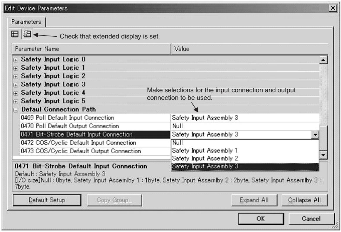
text_image
Edit Device Parameters Parameters Check that extended display is set. Parameter Name Value + Safety Input Logic 0 + Safety Input Logic 1 + Safety Input Logic 2 + Safety Input Logic 3 + Safety Input Logic 4 Make selections for the input connection and output connection to be used. + Safety Input Logic 5 - Default Connection Path 0469 Poll Default Input Connection Safety Input Assembly 3 0470 Poll Default Output Connection Null 0471 Bit-Strobe Default Input Connection Safety Input Assembly 3 0472 COS/Cyclic Default Input Connection Null 0473 COS/Cyclic Default Output Connection Safety Input Assembly 1 Safety Input Assembly 2 0471 Bit-Strobe Default Input Connection Safety Input Assembly 3 Default : Safety Input Assembly 3 [I/O size]Null : 0byte, Safety Input Assembly 1 : 1byte, Safety Input Assembly 2 : 2byte, Safety Input Assembly 3 : 7byte, Default Setup Copy Group... Expand All Collapse All OK Cancel- Download the specified configuration to the DST1-XD0808SL-1.
- Set the Standard Master so that the connection type (Poll, BitStrobe, COS, or Cyclic) and I/O data size agree with the settings that were made in step 1 above.
Note “Null” means that I/O assembly data is not used, i.e., that the data size is 0 bytes. The output connection size for a Bit-Strobe connection is always 0 bytes.
SECTION 4 Specifications
4-1 Specifications 54
4-1-1 Common Specifications 54
4-1-2 Current Consumption and Weights.... 54
4-1-3 DeviceNet Communications Specifications 54
4-2 Indicators.... 56
4-2-1 MS/NS Indicators 56
4-2-2 Configuration Lock Indicator 56
4-2-3 IN PWR/OUT PWR Indicators 57
4-2-4 I/O Indicators 57
4-1 Specifications
4-1-1 Common Specifications
| Item | Specifications |
| Communications power supply voltage | 11 to 25 V DC (Supplied from the communications connector.) |
| I/O power supply voltage | 20.4 to 26.4 V DC (24 V DC, -15% to +10%) |
| EMC | Conforms to IEC61131-2. |
| Vibration resistance | 10 to 57 Hz: 0.35-mm single amplitude,57 to 150 Hz: 50 m/s ^2 |
| Shock resistance | 150 m/s ^2 for 11 msDST1-MRD08SL-1: 100 m/s ^2 for 11ms |
| Operating temperature | -10 to 55°C |
| Relative humidity | 10% to 95% (with no condensation)DST1-MRD08SL-1: 10% to 85% (with no condensation) |
| Operating environment | No corrosive gases |
| Storage temperature | -40 to 70°C |
| Mounting | 35-mm DIN Track |
| Degree of protection | IP20 |
| Overvoltage Category | II |
4-1-2 Current Consumption and Weights
| Model | Communications current consumption | Weight |
| DST1-ID12SL-1 | 100 mA at 24 V DC | 420 g |
| DST1-MD16SL-1 | 110 mA at 24 V DC | 420 g |
| DST1-MRD08SL-1 | 100 mA at 24 V DC | 600 g |
| DST1-XD0808SL-1 | 110 mA at 24 V DC | 420 g |
4-1-3 DeviceNet Communications Specifications
| Item | Specifications | |||
| Communications protocol | Conforms to DeviceNet and DeviceNet Safety. | |||
| Topology | Combination of multi-drop and T-branch connections (for trunk or branch lines) | |||
| Baud rate | 125 kbps, 250 kbps, or 500 kbps | |||
| Communications media | Special 5-wire cable (2 signal lines, 2 power lines, 1 shield line) | |||
| Communications distances | Baud rate | Network length | Branch line length | Total branch line length |
| 500 kbps | 100 m max.(100 m max.) | 6 m max. | 39 m max. | |
| 250 kbps | 250 m max.(100 m max.) | 6 m max. | 78 m max. | |
| 125 kbps | 500 m max.(100 m max.) | 6 m max. | 156 m max. | |
| Values in parentheses are the lengths when using Thin Cables. | ||||
| Communications power supply | 11 to 25 V DC | |||
| Maximum number of nodes | 63 nodes | |||
| DST1-ID12SL-1DST1-MD16SL-1DST1-MRD08SL-1 | DST1-XD0808SL-1 | ||
| Safety I/O Communications | |||
| Number of connections | 4 (See note.) | 2 | |
| Connection type | Single-cast, Multi-cast | Single-cast, Multi-cast | |
| Standard I/O Communications | |||
| Number of connections | 2 | 2 | |
| Connection type | Poll/Bit-strobe/COS/Cyclic | Poll/Bit-strobe/COS/Cyclic | |
Note
Communications are enabled with 15 Safety Masters for each multi-cast connection, but if four connections are used, it is not possible to communicate with more than 30 Safety Masters total.
4-2 Indicators
4-2-1 MS/NS Indicators
This section describes the meanings of MS and NS indicators for the DST1-series Safety I/O Terminals.
The MS (Module Status) indicator displays the status of a node on the network.
The NS (Network Status) indicator displays the status of the entire network.
The MS and NS indicators can be green or red and they can be ON, flashing, or OFF. The meanings indicated by the combination of their colors and status are as given in the following table.
| Indicator | Color | Status | Meaning |
| MS | Green |  | Normal operation status; RUN status (See note.) |
 | Waiting for communications from the Safety Master; Idle status (See note.) | ||
| Red |  | System failure | |
 | Minor failure (Switch settings incorrect, etc.) | ||
| Green/Red |  | The DST1 is performing initialization process or waiting for configuration. | |
| - | [WZW] | Power is not supplied | |
| NS | Green |  | Online connection has been established. |
| [SWH6] | Online connection has not been established. | ||
| Red | [0XX4] | Unable to communicate | |
| [4W3Z] | I/O communication error | ||
| - |  | Not online/Not powered MS |


Note Applicable to the DST1-XD0808SL-1 only.
4-2-2 Configuration Lock Indicator
The LOCK indicator indicates that the configuration data has been locked.
| Indicator | Color | Status | Meaning |
| LOCK | Yellow |  | Lock has been completed with a valid configuration. |
 | Lock has not been completed with a valid configuration. | ||
| [33CV] | Configuration has not been performed. |


4-2-3 IN PWR/OUT PWR Indicators
The IN PWR and OUT PWR indicators indicate the status of the I/O power supplied to the DST1-series Safety I/O Terminals.
| LED Indicators | Color | Status | Meaning |
| IN PWR | Green | Normal status of input power | |
| Input power is not supplied. | |||
| OUT PWR | Green | Normal status of output power | |
| Output power is not supplied.Output power exceeds the upper/lower limit of the power range.A system error has occurred. |

4-2-4 I/O Indicators
The I/O indicators show the ON/OFF and error status of I/O.
Note The indicators are not lit while the DST1-series Safety I/O Terminals is being configured.
| Name | Color | Status | Meaning |
| IN0 to INn(See note.) | Yellow |  | Safety input ON. |
| ■ | Safety input OFF. | ||
| Red |  | • Error detected in safety input circuits.• Discrepancy error has occurred set for Dual Channel Mode. | |
| [IMAGE] | Error detected in the other input circuit set for Dual Channel Mode (no error in this circuit) | ||
| OUT0 to OUTn(See note.) | Yellow |  | Safety output ON. |
| ■ | Safety output OFF. | ||
| Red |  | • Error detected in safety output circuits.• EDM error (See note 2.) | |
 | Error detected in the other output circuit set for Dual Channel Mode (no error in this circuit) |

Note (1) "n" indicates the terminal number.
(2) Applicable to the DST1-XD0808SL-1 only.
SECTION 5
DST1 Series Specifications
5-1 DST1-ID12SL-1 60
5-1-1 Safety Input Specifications.... 60
5-1-2 Test Output Specifications 60
5-1-3 Nomenclature 60
5-1-4 Internal Circuits and Terminal Arrangement 61
5-1-5 Dimensions.... 62
5-2 DST1-MD16SL-1 63
5-2-1 Safety Input Specifications.... 63
5-2-2 Test Output Specifications 63
5-2-3 Safety Output Specifications for Semiconductor Outputs ..... 63
5-2-4 Nomenclature 64
5-2-5 Internal Circuits and Terminal Arrangement 64
5-2-6 Dimensions.... 66
5-3 DST1-MRD08SL-1....67
5-3-1 Safety Input Specifications.... 67
5-3-2 Test Output Specifications 67
5-3-3 Safety Output Specifications for Relay Outputs.... 67
5-3-4 Nomenclature 68
5-3-5 Internal Circuits and Terminal Arrangement 68
5-3-6 Dimensions.... 71
5-4 DST1-XD0808SL-1 72
5-4-1 Safety Input Specifications.... 72
5-4-2 Test Output Specifications 72
5-4-3 Safety Output Specifications for Semiconductor Outputs ..... 72
5-4-4 Nomenclature 72
5-4-5 Internal Circuits and Terminal Arrangement 73
5-4-6 Dimensions 75
5-1 DST1-ID12SL-1
5-1-1 Safety Input Specifications
The following table gives the safety input specifications for the DST1-ID12SL-1.
| Item | Specifications |
| Input type | Sinking input (PNP) |
| ON voltage | 11 VDC min. between each input terminal and G |
| OFF voltage | 5 VDC max. between each input terminal and G |
| OFF current | 1 mA max. |
| Input current | 6 mA |
5-1-2 Test Output Specifications
The following table gives the test output specifications for the DST1-ID12SL-1.
| Item | Specifications |
| Output type | Sourcing output (PNP) |
| Rated output current | 0.7 A |
| Residual voltage | 1.2 V max. between each output terminal and V |
| Leakage current | 0.1 mA max. |
5-1-3 Nomenclature
The following figure shows the names of the parts of the DST1-ID12SL-1.
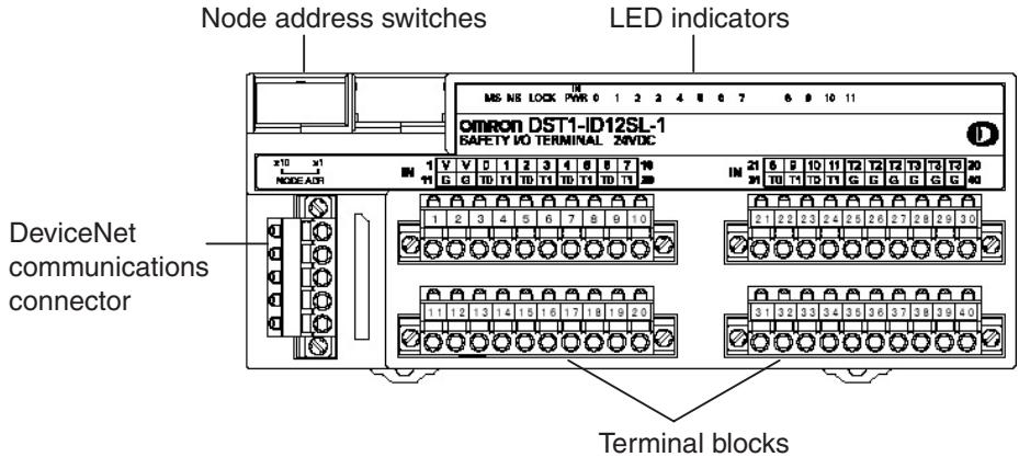
text_image
Node address switches LED indicators MS INS LOCK PWR 0 1 2 3 4 5 6 7 8 9 10 11 omron DST1-ID12SL-1 SAFETY I/O TERMINAL ZND/C x10 x1 NODE A31 DeviceNet communications connector Terminal blocks- Refer to 4-2 Indicators for information on the LED indicators.
- Refer to 2-4 Connecting the Communications Connector for information on the DeviceNet communications connector.
- Refer to 5-1-4 Internal Circuits and Terminal Arrangement for information on the terminal blocks.
5-1-4 Internal Circuits and Terminal Arrangement
The following figure shows the internal circuits of the DST1-ID12SL-1.
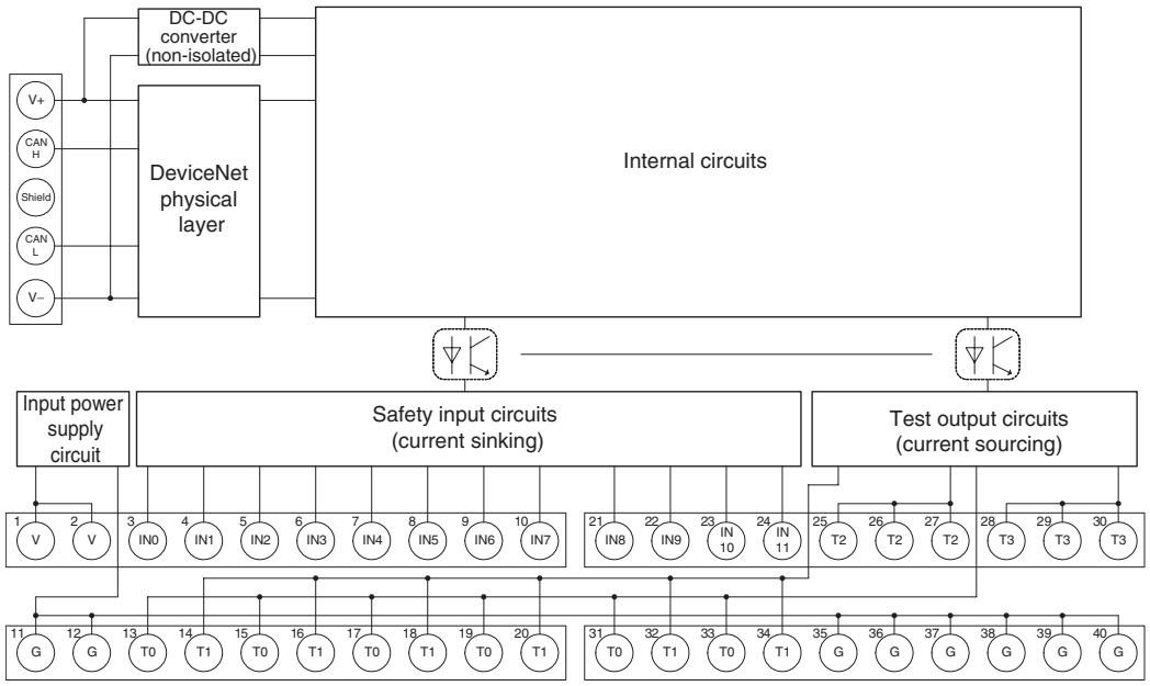
flowchart
graph TD
    A["Internal circuits"] --> B["DeviceNet physical layer"]
    B --> C["DC-DC converter (non-isolated)"]
    C --> D["V+"]
    C --> E["CAN H"]
    C --> F["Shield"]
    C --> G["CAN L"]
    C --> H["V-"]
    B --> I["Input power supply circuit"]
    I --> J["1 V 2 V"]
    I --> K["3 IN0 4 IN1 5 IN2 6 IN3 7 IN4 8 IN5 9 IN6 10 IN7"]
    I --> L["11 G 12 G 13 T0 14 T1 15 T0 16 T1 17 T0 18 T1 19 T0 20 T1"]
    B --> M["Safety input circuits (current sinking)"]
    M --> N["21 IN8 22 IN9 23 IN10 24 IN11"]
    M --> O["25 T2 26 T2 27 T2"]
    M --> P["28 T3 29 T3 30 T3"]
    M --> Q["31 T0 32 T1 33 T0 34 T1"]
    M --> R["35 G 36 G 37 G 38 G 39 G 40 G"]
    M --> S["Output Circuit"]
The following table gives the terminal arrangement of the terminal blocks on the DST1-ID12SL-1.
| Terminals | Names | Functions |
| 1, 2 | V | Power terminals for the input devices and test outputs. (24 VDC) |
| 11, 12 | G | |
| 35 to 40 | G | Common terminalsThe terminals 11, 12 and 35 to 40 are internally connected. |
| 3 to 1021 to 24 | IN0 to IN11 | Terminals for safety inputs |
| 13 to 2025 to 3031 to 34 | T0 to T3 | Terminals for test outputs |
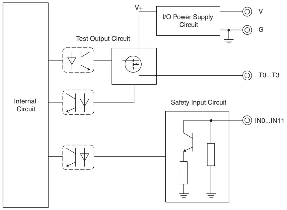
flowchart
graph TD
    A["Internal Circuit"] --> B["Test Output Circuit"]
    A --> C["Safety Input Circuit"]
    B --> D["I/O Power Supply Circuit"]
    C --> E["IN0...IN11"]
    D --> F["V"]
    D --> G["G"]
    D --> H["T0...T3"]
5-1-5 Dimensions
The following figures show the dimensions of the DST1-ID12SL-1 (unit: mm).
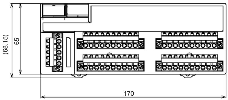
text_image
(68.15) 65 170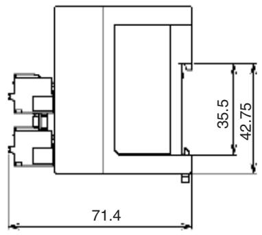
text_image
71.4 35.5 42.755-2 DST1-MD16SL-1
5-2-1 Safety Input Specifications
The following table gives the safety input specifications for the DST1-MD16SL-1.
| Item | Specifications |
| Input type | Sinking input (PNP) |
| ON voltage | 11 VDC min. between each input terminal and G0 |
| OFF voltage | 5 VDC max. between each input terminal and G0 |
| OFF current | 1 mA max. |
| Input current | 6 mA |
5-2-2 Test Output Specifications
The following table gives the test output specifications for the DST1-MD16SL-1.
| Item | Specifications |
| Output type | Sourcing output (PNP) |
| Rated output current | 0.7 A |
| Residual voltage | 1.2 V max. between each output terminal and V0 |
| Leakage current | 0.1 mA max. |
5-2-3 Safety Output Specifications for Semiconductor Outputs
The following table gives the safety output specifications for the Semiconductor outputs on the DST1-MD16SL-1.
| Item | Specifications |
| Output type | Sourcing output (PNP) |
| Rated output current | 0.5 A |
| Residual voltage | 1.2 V max. between each output terminal and V1 |
| Leakage current | 0.1 mA max. |
IMPORTANT In case that a safety output is configured as Safety pulsed test, while this output is in an ON state, the signal sequence shown below is output continuously to enable diagnosis. Confirm the response times of the devices connected to the safety outputs so that the devices do not malfunction due to the OFF pulse.
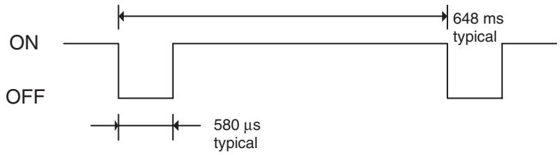
text_image
ON OFF 648 ms typical 580 µs typical5-2-4 Nomenclature
The following figure gives the names of the parts of the DST1-MD16SL-1
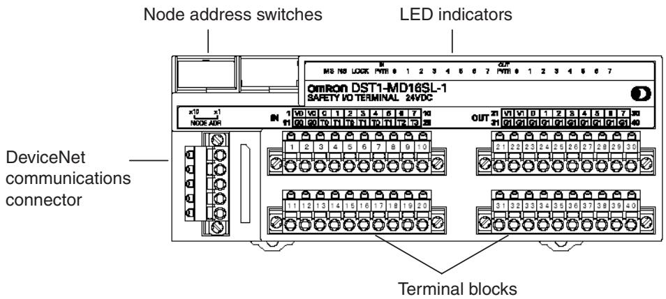
text_image
Node address switches LED indicators OMRON DST1-MD16SL-1 SAFETY I/O TERMINAL 24VDC DeviceNet communications connector Terminal blocks- Refer to 4-2 Indicators for information on the LED indicators.
- Refer to 2-4 Connecting the Communications Connector for information on the DeviceNet communications connector.
- Refer to 5-2-5 Internal Circuits and Terminal Arrangement for information on the terminal blocks.
5-2-5 Internal Circuits and Terminal Arrangement
The following figure shows the internal circuits of the DST1-MD16SL-1.
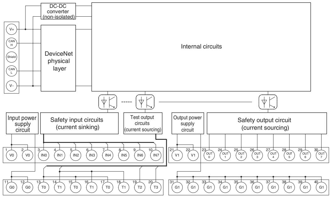
flowchart
graph TD
    A["DC-DC converter (non-isolated)"] --> B["DeviceNet physical layer"]
    C["Input power supply circuit"] --> D["Safety input circuits (current sinking)"]
    D --> E["Internal circuits"]
    F["Output power supply circuit"] --> G["Safety output circuit (current sourcing)"]
    G --> H["Internal circuits"]
    I["1 V0 2 V0"] --> J["3 IN0 4 IN1 5 IN2 6 IN3 7 IN4 8 IN5 9 IN6 10 IN7"]
    K["11 G0 12 G0"] --> L["13 T0 14 T1 15 T0 16 T1 17 T0 18 T1 19 T2 20 T3"]
    M["21 V1 22 V1"] --> N["Output power supply circuit"]
    O["OUT 0 23 OUT 1 24 OUT 2 25 OUT 3 26 OUT 4 27 OUT 5 28 OUT 6 29 OUT 7"]
    P["31 G1 32 G1 33 G1 34 G1 35 G1 36 G1 37 G1 38 G1 39 G1 40 G1"]
    Q["External Circuit"] --> R["DeviceNet physical layer"]
    S["V+"] --> A
    T["CAN H"] --> A
    U["Shield"] --> A
    V["CAN L"] --> A
    W["V-"] --> A
The following table shows the terminal arrangement of the terminal blocks on the DST1-MD16SL-1.
| Terminals | Names | Functions |
| 1,2 | V0 | Power terminals for the input devices and test outputs. (24 VDC) |
| 11,12 | G0 | |
| 3 to 10 | IN0 to IN7 | Terminals for safety inputs |
| 13 to 20 | T0 to T3 | Terminals for test outputs |
| 21, 22 | V1 | Power terminals for the output devices. (24 VDC) |
| 31, 32 | G1 | |
| 23 to 30 | OUT0 to OUT7 | Terminals for safety outputs |
| 33 to 40 | G1 | Common terminals. Terminals 31 to 40 are internally connected. |
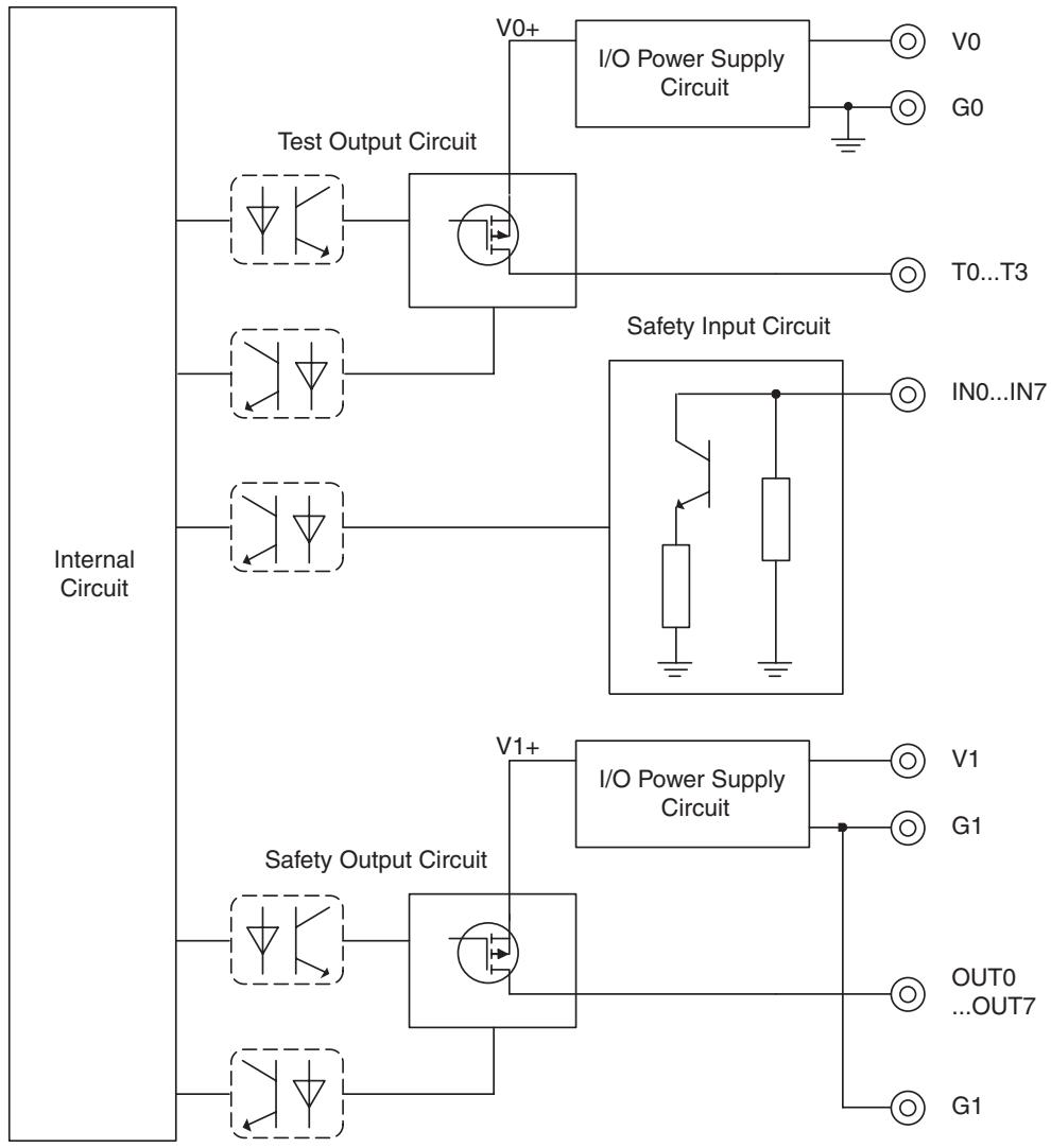
flowchart
graph TD
    A["Internal Circuit"] --> B["Test Output Circuit"]
    A --> C["Safety Input Circuit"]
    A --> D["Safety Output Circuit"]
    B --> E["I/O Power Supply Circuit"]
    C --> F["IN0...IN7"]
    D --> G["I/O Power Supply Circuit"]
    E --> H["V0+"]
    E --> I["G0"]
    F --> J["T0...T3"]
    F --> K["IN0...IN7"]
    G --> L["V1+"]
    G --> M["G1"]
    G --> N["OUT0 ...OUT7"]
    G --> O["G1"]
IMPORTANT Power supply terminal V1 for the outputs is internally monitored. Supply the voltage in the specified range (20.4 to 26.4 VDC). If the voltage is supplied outside this range, voltage will not be supplied to the output circuits.
5-2-6 Dimensions
The following figures show the dimensions of the DST1-MD16SL-1 (unit: mm).
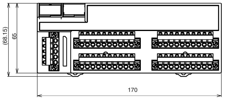
text_image
(68.15) 65 170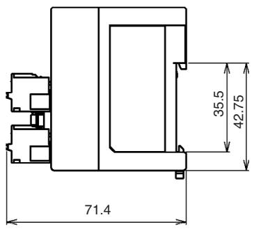
text_image
71.4 35.5 42.755-3 DST1-MRD08SL-1
5-3-1 Safety Input Specifications
The following table gives the safety input specifications for the DST1-MRD08SL-1.
| Item | Specifications |
| Input type | Sinking input (PNP) |
| ON voltage | 11 VDC min. between each input terminal and G0 |
| OFF voltage | 5 VDC max. between each input terminal and G0 |
| OFF current | 1 mA max. |
| Input current | 6 mA |
5-3-2 Test Output Specifications
The following table gives the test output specifications for the DST1-MRD08SL-1.
| Item | Specifications |
| Output type | Sourcing output (PNP) |
| Rated output current | 0.7 A |
| Residual voltage | 1.2 V max. between each output terminal and V0 |
| Leakage current | 0.1 mA max. |
5-3-3 Safety Output Specifications for Relay Outputs
The following table gives the safety output specifications for the DST1-MRD08SL-1.
| Item | Specifications | |
| Relays | G7SA-2A2BEN50205 Class A | |
| Failure rate P level (See note.) (Reference value) | 1 mA at 5 VDC | |
| Rated load for a resistive load | 240 VAC: 2 A30 VDC: 2 A | |
| Durability | Mechanical life expectancy | 5,000,000 operations min.(at approx. 7,200 operations/h) |
| Electrical life expectancy | 100,000 operations min.(at rated load and approx. 1,800 operations/h) | |
Note This value applies to a switching frequency of 300 operations/min.
5-3-4 Nomenclature
The following figure shows the names of the parts of the DST1-MRD08SL-1.
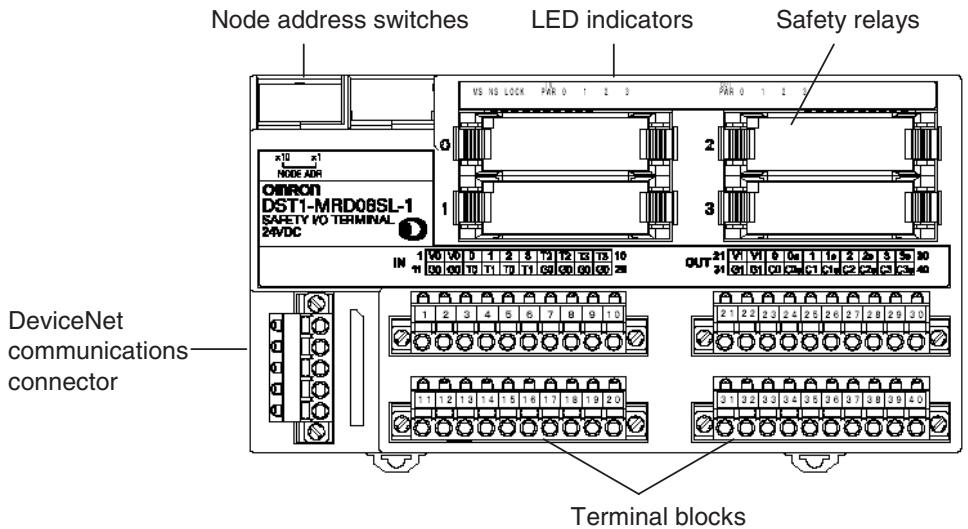
text_image
Node address switches LED indicators Safety relays OMRON DST1-MRD08SL-1 SAFETY I/O TERMINAL 2-RVDC IN 1 V0 V0 1 2 3 4 5 6 7 8 9 10 OUT 21 V1 V1 0 1 1 2 2 3 5 30 DeviceNet communications connector Terminal blocks- Refer to 4-2 Indicators for information on the LED indicators.
- Refer to 2-4 Connecting the Communications Connector for information on the DeviceNet communications connector.
- Refer to 5-3-5 Internal Circuits and Terminal Arrangement for information on the terminal blocks.
5-3-5 Internal Circuits and Terminal Arrangement
The following figure shows the internal circuits of the DST1-MRD08SL-1.
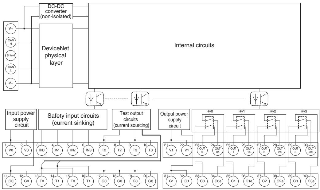
flowchart
graph TD
    subgraph_Internal_Circuits["Internal circuits"]
        A["DeviceNet physical layer"] --> B["DC-DC converter (non-isolated)"]
        B --> C["Input power supply circuit"]
        B --> D["Safety input circuits (current sinking)"]
        B --> E["Test output circuits (current sourcing)"]
        B --> F["Output power supply circuit"]
    end

    subgraph Safety Input Circuit
        G1["V0"] --> H1["1"]
        G2["V0"] --> H2["2"]
        H1 --> I1["3"]
        H2 --> I2["4"]
        I1 --> J1["5"]
        I2 --> J2["6"]
        J1 --> K1["7"]
        J2 --> K2["8"]
        K1 --> L1["T2"]
        K2 --> L2["T2"]
        L1 --> M1["T3"]
        L2 --> M2["T3"]
        M1 --> N1["T0"]
        M2 --> N2["T1"]
        N1 --> O1["G0"]
        N2 --> O2["G0"]
        O1 --> P1["G0"]
        O2 --> P2["G0"]
        P1 --> Q1["G0"]
        P2 --> Q2["G0"]
        Q1 --> R1["G0"]
        Q2 --> R2["G0"]
        R1 --> S1["G0"]
        R2 --> S2["G0"]
        S1 --> T1["G0"]
        S2 --> T2["G0"]
        T1 --> U1["G0"]
        T2 --> U2["G0"]
        U1 --> V1["G1"]
        U2 --> V2["G1"]
        V1 --> W1["G0"]
        V2 --> W2["G0"]
        W1 --> X1["G0"]
        W2 --> X2["G0"]
        X1 --> Y1["G0"]
        X2 --> Y2["G0"]
        Y1 --> Z1["G0"]
        Y2 --> Z2["G0"]
        Z1 --> AA1["G0"]
        Z2 --> AA2["G0"]
        AA1 --> AB1["G0"]
        AA2 --> AB2["G0"]
        AB1 --> AC1["G0"]
        AB2 --> AC2["G0"]
        AC1 --> AD1["G0"]
        AC2 --> AD2["G0"]
        AD1 --> AE1["G0"]
        AD2 --> AE2["G0"]
        AE1 --> AF1["G0"]
        AE2 --> AF2["G0"]
        AF1 --> AG1["G0"]
        AF2 --> AG2["G0"]
        AG1 --> AH1["G0"]
        AG2 --> AH2["G0"]
        AH1 --> AI1["G0"]
        AH2 --> AI2["G0"]
        AI1 --> AJ1["G0"]
        AI2 --> AJ2["G0"]
        AJ1 --> AK1["G0"]
        AJ2 --> AK2["G0"]
        AK1 --> AL1["G0"]
        AK2 --> AL2["G0"]
        AL1 --> AM1["G0"]
        AL2 --> AM2["G0"]
        AM1 --> AN1["G0"]
        AM2 --> AN2["G0"]
        AN1 --> AO1["G0"]
        AN2 --> AO2["G0"]
        AO1 --> AP1["G0"]
        AO2 --> AP2["G0"]
        AP1 --> AQ1["G0"]
        AP2 --> AQ2["G0"]
        AQ1 --> AR1["G0"]
        AQ2 --> AR2["G0"]
        AR1 --> AS1["G0"]
        AR2 --> AS2["G0"]
        AS1 --> AT1["G0"]
        AS2 --> AT2["G0"]
        AT1 --> AU1["G0"]
        AT2 --> AU2["G0"]
        AU1 --> AV1["G0"]
        AU2 --> AV2["G0"]
        AV1 --> AW1["G0"]
        AW1 --> AX1["G0"]
        AW2 --> AX2["G0"]
        AX3["Internal circuits"] --> A
    subgraph Safety Input Circuit
        B
    end

    subgraph Power Supply Circuit
        G4["V+"] & G5["V-"] & G6["V+"] & G7["V-"] & G8["V+"] & G9["V-"] & G10["V+"] & G11["V-"] & G12["V+"] & G13["V-"] & G14["V+"] & G15["V-"] & G16["V+"] & G17["V-"] & G18["V+"] & G19["V-"] & G20["V+"] & G21["V-"] & G22["V+"] & G23["V-"] & G24["V+"] & G25["V-"] & G26["V+"] & G27["V-"] & G28["V+"] & G29["V-"] & G30["V+"] & G31["V-"] & G32["V+"] & G33["V-"] & G34["V+"] & G35["V-"] & G36["V+"] & G37["V-"] & G38["V+"] & G39["V-"] & G40["V+"] & G41["V-"] & G42["V+"] & G43["V-"] & G44["V+"] & G45["V-"] & G46["V+"] & G47["V-"] & G48["V+"] & G49["V-"] & G50["V+"] & G51["V-"] & G52["V+"] & G53["V-"] & G54["V+"] & G55["V-"] & G56["V+"] & G57["V-"] & G58["V+"] & G59["V-"] & G60["V+"] & G61["V-"] & G62["V+"] & G63["V-"] & G64["V+"] & G65["V-"] & G66["V+"] & G67["V-"] & G68["V+"] & G69["V-"] & G70["V+"] & G71["V-"] & G72["V+"] & G73["V-"] & G74["V+"] & G75["V-"] & G76["V+"] & G77["V-"] & G78["V+"] & G79["V-"] & G80["V+"] & G81["V-"] & G82["V+"] & G83["V-"] & G84["V+"] & G85["V-"] & G86["V+"] & G87["V-"] & G88["V+"] & G89["V-"] & G90["V+"] & G91["V-"] & G92["V+"] & G93["V-"] & G94["V+"] & G95["V-"] & G96["V+"] & G97["V-"] & G98["V+"] & G99["V-"] & H00["V+"]
The following table shows the terminal arrangement of the terminal blocks on the DST1-MRD08SL-1.
| Terminals | Names | Functions |
| 1, 2 | V0 | Power terminals for the input devices, test outputs and internal relay feedback monitors. (24 VDC) |
| 11, 12 | G0 | |
| 17 to 20 | G0 | Common terminals. Terminals 11, 12, and 17 to 20 are internally connected. |
| 3 to 6 | IN0 to IN3 | Terminals for safety inputs |
| 7 to 1013 to 16 | T0 to T3 | Terminals for test/standard outputs |
| 21, 22 | V1 | Power terminals for driving internal relays. (24 VDC) |
| 31, 32 | G1 | |
| 23 to 3033 to 40 | OUT0 to OUT3C0 to C3OUT0e to OUT3eC0e to C3e | Terminals for safety outputsOutputs of terminals 23/33 (OUT0) and 24/34 (OUT0e) are the same.Output of terminals 25/35 (OUT1) and 26/36 (OUT1e) are the same.Output of terminals 27/37 (OUT2) and 28/38 (OUT2e) are the same.Output of terminals 29/39 (OUT3) and 30/40 (OUT3e) are the same. |
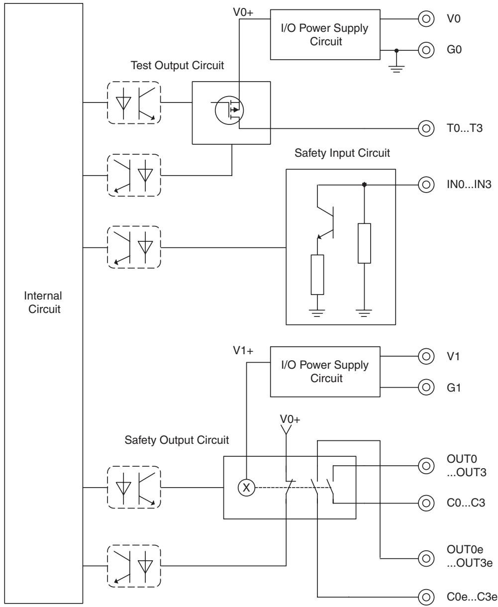
flowchart
graph TD
    A["Internal Circuit"] --> B["Test Output Circuit"]
    A --> C["Safety Input Circuit"]
    A --> D["Safety Output Circuit"]
    B --> E["I/O Power Supply Circuit"]
    C --> F["I/O Power Supply Circuit"]
    D --> G["I/O Power Supply Circuit"]
    E --> H["V0+"]
    E --> I["G0"]
    E --> J["T0...T3"]
    C --> K["IN0...IN3"]
    D --> L["V1+"]
    D --> M["V0+"]
    D --> N["OUT0...OUT3"]
    D --> O["C0...C3"]
    D --> P["OUT0e...OUT3e"]
    D --> Q["C0e...C3e"]
! WARNING
For the DST1-MRD08SL-1, isolating transformers, such as TR1, that are used to isolate between overvoltage categories III and II must conform to IEC60742, and the insulation between the primary input and secondary output must satisfy at least the basic insulation standards of overvoltage category III.
One side of the secondary output of the isolating transformer must be grounded to prevent electrical shock in case of short-circuiting to the ground or to the frame of the isolating transformer.
To protect the isolating transformer and to prevent electrical shock in case of short-circuiting to the frame, insert fuses according to transformer specifications, i.e. at points F1, F2, and F3.
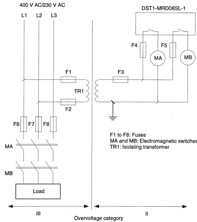
text_image
400 V AC/230 V AC L1 L2 L3 F1 TR1 F2 F6 F7 F8 MA MB Load III Overvoltage category II DST1-MRD08SL-1 F4 F5 MB MA F3 F1 to F8: Fuses MA and MB: Electromagnetic switches TR1: Isolating transformer
For Model DST1-MRD08SL-1, Insert a fuse rated at 3.15 A or less for each output terminal to protect safety output contacts from welding.
Confirm the fuse selection with the fuse manufacturer to ensure the dependability of the characteristics of the connected load.

IMPORTANT
- Supply power to both V0 and V1. The states of the relay contacts are internally monitored from the power supply of V 0.
- Power supply terminal V1 for the outputs is internally monitored. Supply the voltage in the specified range (20.4 to 26.4 VDC). If the voltage is supplied outside this range, voltage will not be supplied to the output circuits.
5-3-6 Dimensions
The following figures show the dimensions of the DST1-MRD08SL-1 (unit: mm).
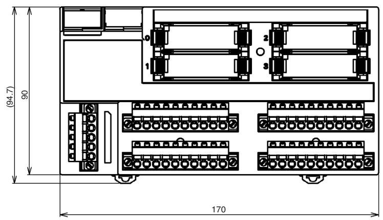
text_image
(94.7) 90 170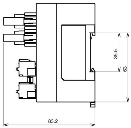
text_image
83.2 35.5 635-4 DST1-XD0808SL-1
5-4-1 Safety Input Specifications
The following table gives the safety input specifications for the DST1-XD0808SL-1.
| Item | Specifications |
| Input type | Sinking input (PNP) |
| ON voltage | 11 VDC min. between each input terminal and G0 |
| OFF voltage | 5 VDC max. between each input terminal and G0 |
| OFF current | 1 mA max. |
| Input current | 6 mA |
5-4-2 Test Output Specifications
The following table gives the test output specifications for the DST1-XD0808SL-1.
| Item | Specifications |
| Output type | Sourcing output (PNP) |
| Rated output current | 0.7 A |
| Residual voltage | 1.2 V max. between each output terminal and V0 |
| Leakage current | 0.1 mA max. |
5-4-3 Safety Output Specifications for Semiconductor Outputs
The following table gives the safety output specifications (for semiconductor outputs) for the DST1-XD0808SL-1.
| Item | Specifications |
| Output type | Sourcing output (PNP) |
| Rated output current | 0.5 A |
| Residual voltage | 1.2 V max. between each output terminal and V1 |
| Leakage current | 0.1 mA max. |
When the safety output channel mode for a safety output terminal is set to Safety Pulse Test, the following pulse signal is output when the safety output turns ON. Confirm the input response times for control devices connected the safety outputs so that the devices do not malfunction due to the OFF pulse.
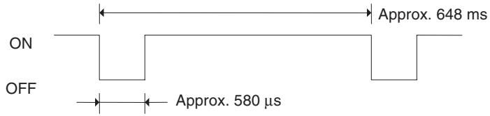
other
| Signal | Approx. Time (ms) | |--------|-------------------| | ON | Approx. 648 ms | | OFF | Approx. 580 µs |5-4-4 Nomenclature
The following figure shows the names of the DST1-XD0808SL-1.
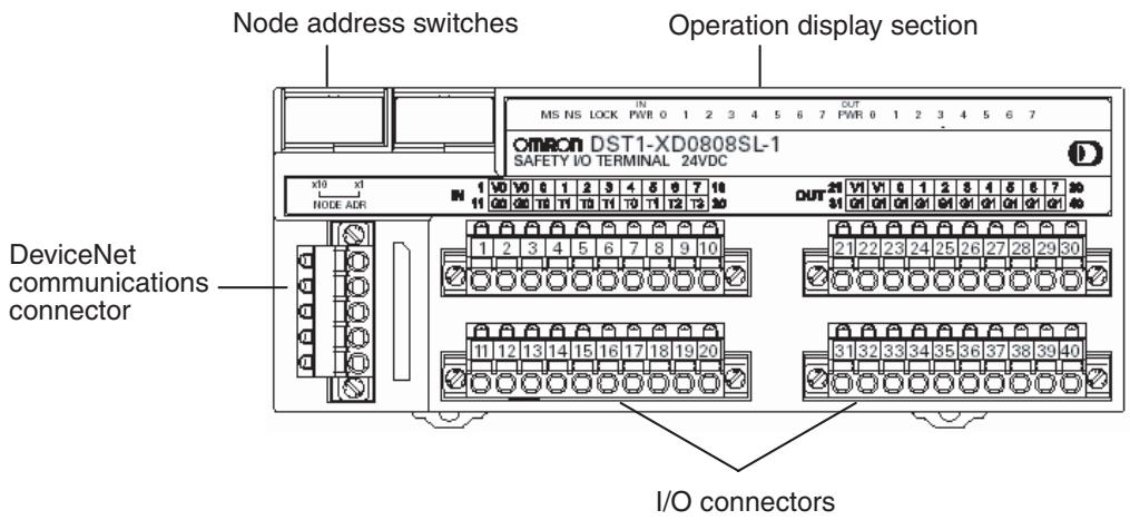
text_image
Node address switches Operation display section OMRON DST1-XD0808SL-1 SAFETY I/O TERMINAL 24VDC x10 x1 NODE ADR DeviceNet communications connector I/O connectors- Refer to 4-2 Indicators for details on the LED indicators.
- Refer to 2-4 Connecting the Communications Connector for details on the DeviceNet communications connector.
- Refer to 5-4-5 Internal Circuits and Terminal Arrangement for details on the terminal arrangement.
5-4-5 Internal Circuits and Terminal Arrangement
The following diagram shows the internal circuits of the DST1-XD0808SL-1.
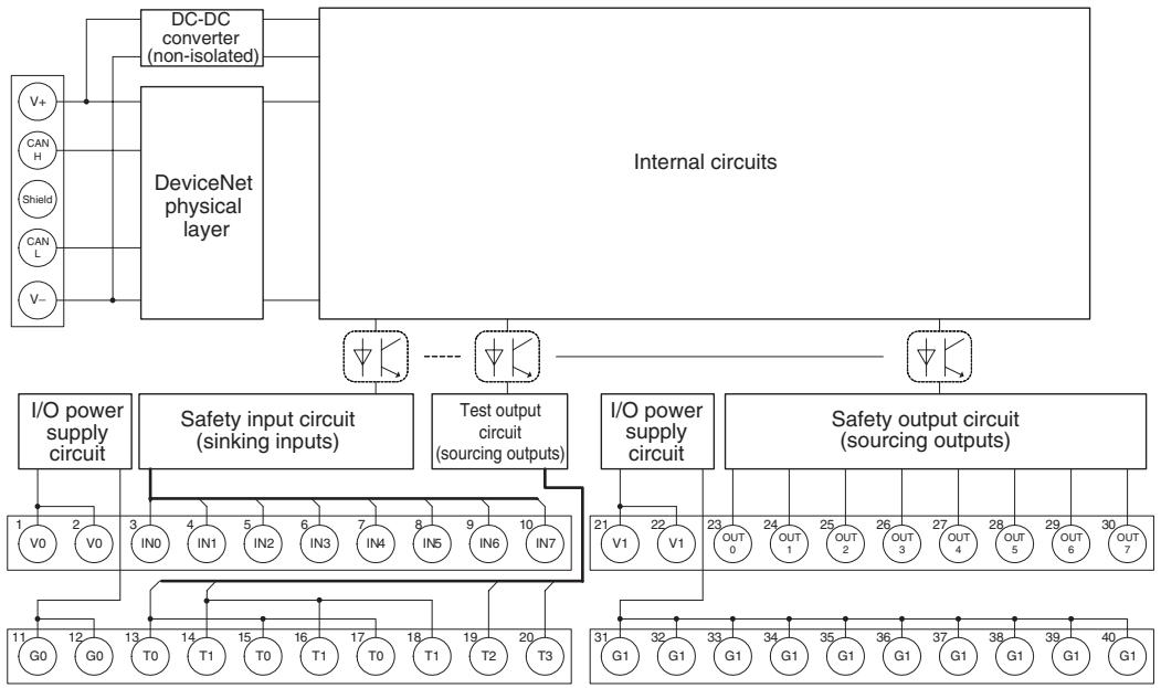
flowchart
graph TD
    A["Internal circuits"] --> B["DeviceNet physical layer"]
    B --> C["DC-DC converter (non-isolated)"]
    B --> D["Internal circuits"]
    D --> E["I/O power supply circuit"]
    D --> F["Safety input circuit (sinking inputs)"]
    D --> G["Test output circuit (sourcing outputs)"]
    D --> H["I/O power supply circuit"]
    D --> I["Safety output circuit (sourcing outputs)"]
    E --> J["1 V0 2 V0"]
    E --> K["3 IN0 4 IN1 5 IN2 6 IN3 7 IN4 8 IN5 9 IN6 10 IN7"]
    F --> L["21 V1 22 V1"]
    F --> M["OUT 0 23 OUT 1 24 OUT 2 25 OUT 3 26 OUT 4 27 OUT 5 28 OUT 6 29 OUT 7"]
    G --> N["31 G1 32 G1 33 G1 34 G1 35 G1 36 G1 37 G1 38 G1 39 G1 40 G1"]
    H --> O["11 G0 12 G0 13 T0 14 T1 15 T0 16 T1 17 T0 18 T1 19 T2 20 T3"]
    I --> P["Output"]
    style A fill:#f9f,stroke:#333
    style D fill:#ccf,stroke:#333
| Terminals | Names | Functions |
| 1, 2 | V0 | Power terminals for input devices and test outputs (24 VDC) |
| 11, 12 | G0 | |
| 3 to 10 | IN0 to IN7 | Terminals for safety inputs |
| 13 to 20 | T0 to T3 | Terminals for test outputs |
| 21, 22 | V1 | Power terminals for output devices (24 VDC) |
| 31, 32 | G1 | |
| 23 to 30 | OUT0 to OUT7 | Terminals for safety outputs |
| 33 to 40 | G1 | Common terminals. Terminals 31 to 40 are internally connected. |
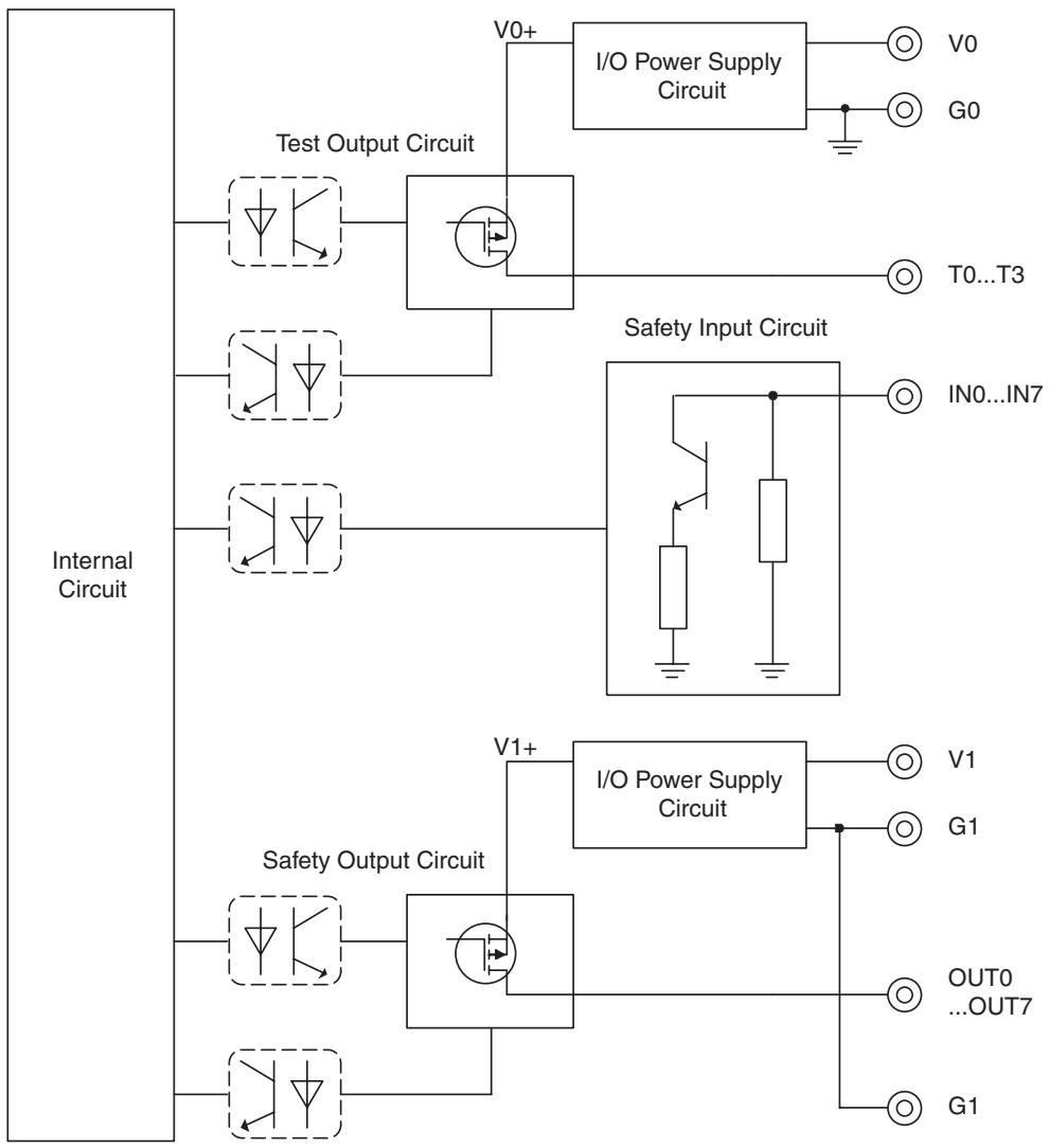
flowchart
graph TD
    A["Internal Circuit"] --> B["Test Output Circuit"]
    A --> C["Safety Input Circuit"]
    A --> D["Safety Output Circuit"]
    B --> E["I/O Power Supply Circuit"]
    C --> F["IN0...IN7"]
    D --> G["I/O Power Supply Circuit"]
    E --> H["V0+"]
    E --> I["G0"]
    F --> J["T0...T3"]
    G --> K["V1"]
    G --> L["G1"]
    D --> M["OUT0...OUT7"]
    D --> N["G1"]
Note Power supply terminal V1 for the output devices is internally monitored. Supply the voltage in the specified range (20.4 to 26.4 VDC). If the voltage is supplied outside this range, voltage will not be supplied to the output circuits.
5-4-6 Dimensions
The following figures show the dimensions of the DST1-XD0808SL-1 (unit: mm).
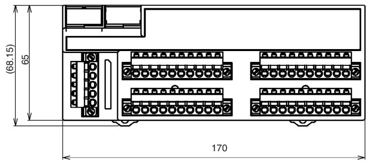
text_image
(68.15) 65 170
text_image
71.4 35.5 42.75SECTION 6
Response Performance
6-1 Reaction Time.... 78
6-1-1 Reaction Time Concept 78
6-1-2 Input Reaction Time 78
6-1-3 Output Reaction Time.... 78
6-1-4 Local Input and Local Output Reaction Times....78
6-1 Reaction Time
6-1-1 Reaction Time Concept
The reaction time is the maximum time required for stopping an output, taking into account errors that may occur in safety chains (logical connections for creating safety devices, consisting of input devices, control devices including remote I/O devices, and output devices). The safety distance is found based on the reaction time.
6-1-2 Input Reaction Time
The input reaction time is the time from when an input terminal signal is changed until an output is sent to the network. The input reaction time is determined as follows:
Input reaction time = 16.2 ms + Input ON/OFF delay time
The input reaction time for the safety input logic result of the DST1-XD0808SL-1 is as follows:
Input reaction time = 22.2 ms + Input ON/OFF delay time
Note For details on reaction times for the entire system, refer to the DeviceNet Safety System Configuration Manual (Cat. No. Z905).
6-1-3 Output Reaction Time
The output reaction time is the time from when a network signal is received until the output terminal is changed. The output reaction time is determined as follows:
Output reaction time (DST1-MD16SL-1) = 6.2 ms
Output reaction time (DST1-MRD08SL-1) = 26.2 ms
Output reaction time (DST1-XD0808SL-1) = 6.2 ms + Output ON/OFF delay time
Note For details on reaction times for the entire system, refer to the DeviceNet Safety System Configuration Manual (Cat. No. Z905).
6-1-4 Local Input and Local Output Reaction Times
The DST1-XD0808SL-1 can stop local outputs according to local input status by using logic operations. In such cases, the Unit can independently calculate the reaction time.
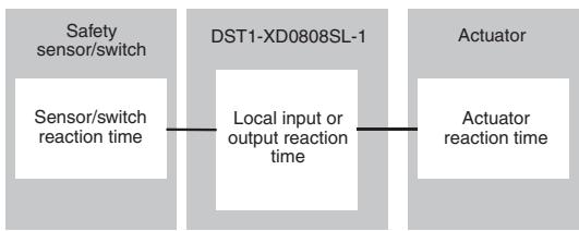
flowchart
graph LR
    A["Safety sensor/switch"] --> B["Sensor/switch reaction time"]
    B --> C["DST1-XD0808SL-1"]
    C --> D["Local input or output reaction time"]
    D --> E["Actuator"]
    E --> F["Actuator reaction time"]
Local input or output reaction time = 18.7 ms + Input ON/OFF delay time + Output ON/OFF delay time
SECTION 7
Troubleshooting and Maintenance
7-1 Indicators and Error Processing 80
7-2 Troubleshooting 81
7-2-1 Safety Input Errors 81
7-2-2 Test Output Errors.... 82
7-2-3 Safety Output Errors.... 83
7-3 Error History 84
7-4 Maintenance 86
7-4-1 Cleaning 86
7-4-2 Inspection 86
7-4-3 Replacing the DST1 87
7-1 Indicators and Error Processing
| MS | NS | LOCK | I/O PWR | I/O | Description | Probable cause and remedy | |||
| Green | Red | Green | Red | Yellow | Green | Yellow | Red | ||
| (XYZA) | GND31 | GND31 | GND41 | GND71 | - | - | - | Safety I/O communications in progress (normal status) | |
| - | - | - | - | - | - | RUN status (DST1-XD0808SL-1 only) | |||
| GND42 | GND41 | GND42 | GND42 | GND51 | - | - | - | Standard I/O communications or message communications in progress (normal status) | |
| GND43 | GND41 | GND42 | GND42 | ■ | - | - | - | The DST1 performing initializa-tion process or waiting for config-uration. | |
| FMD1 | GND41 | GND51 | GND50 | - | - | - | - | Waiting for safety or standard connection | |
| GND44 | GND41 | GND44 | GND44 | - | - | - | - | Communications timeout | Check the following items and restart the DST1.Are lengths of cables (trunk and branch lines) correct?Are cables broken or loose?Are Terminating Resistors connected to both ends of the trunk line only?Is noise interference excessive? |
| GND45 | GND41 | GND41 | GND41 | - | - | - | - | ||
| Node address duplication | Reset the DST1 so that it has a unique node address, and then restart the DST1. | ||||||||
| GND42 | GND41 | GND42 | GND42 | - | - | - | - | Waiting for completion of node address duplication check at the master | Reset the DST1 so that it has a unique node address, and then restart the DST1. |
| GND43 | GND41 | GND43 | GND43 | - | - | - | - | Switch settings are incorrect | Check the node address, and then restart the DST1. |
| GND45 | GND41 | GND44 | GND43 | GND44 | GND45 | GND46 | GND45 | System failure | Check to see if the positive side of the power supply is in contact with the signal line.Replace the DST1 if the system failure still occurs after turning the power supply ON again. |
| GND41 | GND41 | GND41 | GND41 | GND42 | GND41 | GND41 | GND41 | Input/output power is not supplied. | Check the following items.Are cables broken?Is the I/O power voltage within specifications? |
| GND42 | GND41 | GND41 | GND41 | GND41 | GND41 | GND41 | GND41 | An error occurred in an input/output circuit. | Check the following items.Has a ground fault occurred in the signal line?Is the signal line broken?Are there any troubles with the connected device?Is the power source (positive side) in contact with the signal line?Has a short-circuit occurred in the signal line?Is the discrepancy time setting suitable?Is the I/O power supply voltage within specifications?Did an EDM error occur?Details on the error can be read from the Network Configurator. |
| GND43 | GND41 | GND41 | GND41 | GND41 | GND41 | GND41 | GND41 | ||
| GND44 | GND41 | GND41 | GND41 | GND41 | GND41 | GND41 | GND41 | When dual channels are set: An error occurred in the other channel. | |


7-2 Troubleshooting
I/O errors can be read out from safety input status, test output status, and safety output status.
Status data when I/O is normal: ON (1)
Status data when an error occurs I/O: OFF (0)
The details of errors can be read out by using explicit messages and the Network Configurator.
Note For I/O error latch time settings, the OFF status is maintained for at least the error latch time (0 to 65,530 ms, in increments of 10 ms) when individual safety input status turns OFF.
7-2-1 Safety Input Errors
| Code | Error | Probable cause | Countermeasure |
| 01 hex | Configuration invalid | The configuration is invalid. | Configure the DST1 correctly. |
| 02 hex | External test signal failure | 1. The power source (positive side) is in contact with the input signal line.2. Short-circuit between input signal lines3. Trouble with the connected device | 1. 2. Check the wiring.3. Replace the connected device. |
| 03 hex | Internal input failure | Trouble with the internal circuits | Replace the DST1 if the system failure still occurs after turning the power supply ON again. |
| 04 hex | Discrepancy error | 1. Ground fault or break in an input signal line2. Trouble with the connected device3. The discrepancy time setting is not satisfied. | 1. Check the wiring.2. Replace the connected device.3. Change the time setting. |
| 05 hex | Failure of the associated dual-channel input | Dual channels are set and an error occurred in the other channel. | Remove the error in the other channel. |
Explicit Message for Reading the Cause of the Error
| Explicit message | Read/write | Function | Command | Response | ||||
| Service code | Class ID | Instance ID | Attribute ID | Data size | ||||
| Safety Input Cause of Error Information Read | Read | Reads the cause for the normal flag (1 to 12) speci-fied by the instance ID turn-ing OFF. (See note.) | 0E hex | 3D hex | 01 to 0C hex | 6E hex | - | 0: No error Or error code |
Note The instance numbers for safety inputs 0 to 11 are 1 to 12 (01 to 0C hex), respectively.
7-2-2 Test Output Errors
| Code | Error | Probable cause | Countermeasure |
| 01 hex | Configuration invalid | The configuration is invalid. | Configure the DST1 correctly. |
| 02 hex | Overload detected | 1. Ground fault or short-circuit of an output signal line2. Trouble with the connected device | 1. Check the wiring.2. Replace the connected device. |
| 05 hex | Stuck-at-high detected | 1. The power source (positive side) is in contact with the output signal line.2. Trouble with the internal circuit | 1. Check the wiring.2. Replace the DST1. |
| 06 hex | Undercurrent was detected using muting lamp | Trouble with the connected device | Replace the connected device. |
Explicit Message for Reading the Cause of the Error
| Explicit message | Read/write | Function | Command | Response | ||||
| Service code | Class ID | Instance ID | Attribute ID | Data size | ||||
| Test Output Cause of Error Information Read | Read | Reads the cause for the normal flag (1 to 4) specified by the instance ID turning OFF. (See note.) | 0E hex | 09 hex | 01 to 04 hex | 76 hex | - | 0 = No error Or error code |
Note The instance numbers for test outputs 0 to 3 are 1 to 4 (01 to 04 hex), respectively.
7-2-3 Safety Output Errors
| Code | Error | Probable cause | Countermeasure |
| 01 hex | Configuration invalid | The configuration is invalid. | Configure the DST1 correctly. |
| 02 hex | Overcurrent detected | Trouble with the connected device | Replace the connected device. |
| 03 hex | Short circuit to low | Ground fault of the output signal line | Check the wiring. |
| 04 hex | Stuck at high | 1. The power source (positive side) is in contact with the output signal line.2. Trouble with the internal circuit3. The I/O power supply voltage is not within specifications. | 1. Check the wiring.2. Replace the DST1.3. Make sure the I/O power supply voltage is within specifications. |
| 05 hex | Failure of the associated dual-channel input | Dual channels are set and an error occurred in the other channel. | Remove the error in the other channel. |
| 06 hex | Internal relay relevant circuit error (DST1-MRD08SL-1 only) | Trouble with the internal circuit (MRD only) | Replace the DST1 if the system failure still occurs after turning the power supply ON again. |
| 07 hex | Relay failure (DST1-MRD08SL-1 only) | Trouble with the relay (MRD only) | Replace the relay. |
| 08 hex | Dual channel violation | Wrong setting for output data | Check the program. |
| 09 hex | Cross connection detected | Short-circuit between output signal lines. | Check the wiring. |
| 0x0A | EDM error (DST1-XD0808SL-1 only) | 1. Break in the EDM feedback signal line, or contact with power supply (positive side), or ground fault2. Contactor or relay contact weld fault | 1. Check the wiring.2. Replace the contactor or relay. |
Explicit Message for Reading the Cause of the Error
| Explicit message | Read/write | Function | Command | Response | ||||
| Service code | Class ID | Instance ID | Attribute ID | Data size | ||||
| Safety Output Cause of Error Information Read | Read | Reads the cause for the normal flag (1 to 8) specified by the instance ID turning OFF. (See note.) | 0E hex | 3B hex | 01 to 08 hex | 6E hex | - | 0: No error Or error code |
Note The instance numbers for safety outputs 0 to 7 are 1 to 8 (01 to 08 hex), respectively.
7-3 Error History
The DST1-series Safety I/O Terminals internally store up to 10 error history records. The history is updated each time an error occurs. When more than ten records exist, the oldest record will be deleted. The error history can be read using the Network Configurator.
| Message | Countermeasure |
| DST1 Series System Failures | |
| System Failure | Check to see if the positive side of the power supply is in contact with the signal line.Replace the DST1 if the system failure still occurs after turning ON the power. |
| Invalid Configuration | Configure the DST1 correctly. |
| DeviceNet Communications Errors | |
| Switch Setting Mismatch | Check to see if the node address is the same as the node address used for the previous configuration.If not, set the node address to that of the previous configuration, or configure the DST1 again.If the error occurs again, replace the DST1. |
| Duplication MAC ID | Check the node addresses of other nodes.After setting the node addresses to eliminate address duplication, turn ON the power to the DST1 again. |
| Transmission Timeout | Check the following items.Are cable lengths (trunk and branch lines) correct?Are cables broken or loose?Are Terminating Resistors connected to both ends of the trunk line and only to both ends of the trunk line?Is noise interference excessive? |
| BusOff | |
| Standard IO Connection Timeout | |
| Safety I/O Connection Timeout | |
| Test Output Terminal-related Failures | |
| Stuck-at-high Detected at Test Output | Check to see if the positive side of the power source is in contact with the output signal line.If the wiring is okay, replace the DST1. |
| Overload Detected at Test Output | Check the wiring to see if a ground fault occurred in the output signal line. |
| Undercurrent is detected using muting lamp | Check the wiring to see if an output signal line is broken.If the wiring is okay, replace the external lamp. |
| Safety Input Terminal-related Failures | |
| Discrepancy Error at Safety Input | Check the following points:Make sure the input signal wire is not contacting the positive side of the power source.Make sure the input signal wire does not have an earth fault.Make sure the input signal wire is not disconnected.Make sure there is not a short circuit between input signal wires.Make sure a failure has not occurred in the connected device.Make sure the set value of the discrepancy time is valid.To recover from these failures, the following conditions are required:The latch input error time must have passed, and the cause of the error must have been removed.The target safety input terminal inputs must turn OFF.When changing the discrepancy time, reconfiguration is required. |
| External Connected Device Failure at Safety Input | |
| Internal Input Failure at Safety Input | Replace the DST1 if the system failure still occurs after turning the power supply ON again. |
| Safety Output Terminal-related Failures | |
| Cross Connection Detected at Safety Output | Check the following points:Make sure there is no overcurrent for the output.Make sure the output signal wire does not have an earth fault.Make sure the output signal wire is not contacting the positive side of the power supply.Make sure there is not a short circuit between output signal wires.Make sure the power supply voltage is set within the specification range.To recover from these failures, the following conditions are required:The latch output error time must have passed, and the cause of the error must have been removed.The output signal from the user application for the target safety output must turn OFF. |
| Stuck-at-high Detected at Safety Output | |
| Short Circuit Detected at Safety Output | |
| Over Current Detected at Safety Output | |
| Dual Channel Output failure | Check the program to see if output data for dual channels are the same. |
| Internal Relay Relevant Circuit Error | Check whether noise interference is excessive. |
| Relay Failure | Replace the safety relay. |
| EDM error | Check the following items.Is the output signal line broken?Is the output signal line grounded?Is the output signal line in contact with the power supply (positive side)?Is there a contactor or relay contact weld fault? |
| Maintenance Information | |
| Total On Time or Contact Operation Counter Exceeded Threshold | --- |
| Operation Time Exceeded Threshold | --- |
| Unit Conduction Time Exceeded Threshold | --- |
| Network PS Voltage Fell Below Threshold | --- |
| Error Related to Power Supply for I/O | |
| Output PS Voltage Low | Check the following items.Are cables broken?Is the power supply voltage within specifications? |
| Input PS Voltage Low | |
7-4 Maintenance
This section describes the routine cleaning and inspection recommended as regular maintenance. Handling methods when replacing the DST1-series Safety I/O Terminals are also explained here.
7-4-1 Cleaning
Clean the DST1-series Safety I/O Terminals regularly as described below to keep the network in optimal operating condition.
- Wipe the DST1-series Safety I/O Terminals with a dry, soft cloth for regular cleaning.
- When dust or dirt cannot be removed with a dry cloth, dampen the cloth with a neutral cleanser (2%), wring out the cloth, and wipe the DST1-series Safety I/O Terminals.
- Smudges may remain on the DST1-series Safety I/O Terminals from gum, vinyl, or tape that was left on for a long time. Remove these smudges when cleaning.
Note
Never use volatile solvents, such as paint thinner or benzene, or chemical wipes to clean the DST1-series Safety I/O Terminals. These substances may damage the surface of the DST1-series Safety I/O Terminals.
7-4-2 Inspection
Inspect the system periodically to keep it in optimal operating condition.
In general, inspect the system once every 6 to 12 months, but inspect more frequently if the system is used in high-temperature, humid, or dusty conditions.
Inspection Equipment
Prepare the following equipment before inspecting the system.
Equipment Required for Regular Inspection
Phillips screwdriver
A flat-blade screwdriver
A screwdriver for connecting communications connectors
A tester (or a digital voltmeter)
Industrial alcohol and a clean cloth
Other Equipment That May Be Required
A synchroscope
An oscilloscope
A thermometer or hygrometer
Inspection Procedure
Check the items in the following table and correct any condition that is below standard.
| Inspection item | Details | Standard | Equipment |
| Environmental conditions | Are ambient and panel temperatures correct? | Refer to the specifications for each DST1. | Thermometer |
| Are ambient and panel humidity correct? | Refer to the specifications for each DST1. | Hygrometer | |
| Has dust or dirt accumulated? | No dust or dirt | Visual inspection | |
| Installation conditions | Is the DST1 installed securely? | No looseness | Phillips screwdriver |
| Are the connectors of the communications cables fully inserted? | No looseness | A flat-blade screwdriver | |
| Are the external wiring screws tight? | No looseness | A flat-blade screwdriver | |
| Are the connecting cables undamaged? | No external damage | Visual inspection | |
| Safety relay operation | Does the safety relay contact go to OFF state? | No welded contacts | Visual inspection |
IMPORTANT
- The maintenance interval for the relay contacts must not exceed a period of 6 month to meet safety category 4 in accordance with EN 954-1.
- The G7SA-2A2B must be used when replacing safety relays.
7-4-3 Replacing the DST1
The network consists of the DeviceNet Unit (master) and DST1 Terminals. The entire network is affected when a DST1 is faulty, so a faulty DST1 must be repaired or replaced quickly. We recommend having spare DST1 Terminals available to restore network operation as quickly as possible.
Precautions for Replacing the DST1
Observe the following precautions when replacing a faulty DST1.
After replacement, make sure that there are no errors in the new DST1.
When a DST1 is being returned for repair, attach a detailed description of the problem and return the DST1 to your OMRON representative.
If there is a faulty contact, try wiping the contact with a clean, lint-free cloth dampened with alcohol.
Settings after Replacing a DST1
After replacing a DST1, set the new DST1's switches and configuration data to the same settings that were used on the old DST1.

WARNING
Safety functions may be impaired and serious injury may occasionally occur. When replacing a device, configure the replacement device suitably and confirm that it operate correctly.

SECTION 8
Wiring Examples
8-1 Wiring and Configuration 90
8-2 Examples of Wiring for Each Application 91
8-2-1 Emergency Stop Switch Dual Channel Inputs with Manual Reset. 91
8-2-2 Two-Hand Input 92
8-2-3 User Mode Switch Input....93
8-2-4 Muting Lamp Output 94
8-2-5 Limit Switch Dual Channel Inputs and a Manual Reset ..... 95
8-2-6 Safety Light Curtain Input 96
8-2-7 Semiconductor Outputs for Dual Channel Mode 97
8-2-8 Relay Outputs with Dual Channel Mode and EDM Input ..... 98
8-3 Logic Terminal Wiring Examples.... 99
8-3-1 Stopping Outputs by Using an Emergency Stop Switch or a Signal from a Safety Master 99
8-1 Wiring and Configuration
The following table shows input device connection methods and configuration.
| Connected device | Schematic diagram | Configuration |
Reset switch 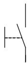 | Connect the switch between IN0 and T0. 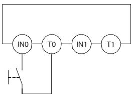 | Safety Input used as “Single Channel input” without test output.Test output used as power supply output. |
Connect the switch between 24 V DC and IN0. 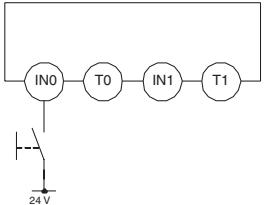 | Safety Input used as “Single Channel input” without test output. | |
Emergency stop switch Door monitor 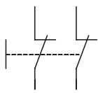 | Connect the switches between IN0 and T0, and IN1 and T1. 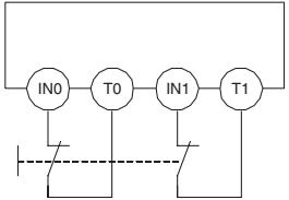 | Safety Inputs used as “Dual Channel input” with test output.Test outputs used as "Pulse Test Output". |
Connect the switches between T0 and IN0, IN. 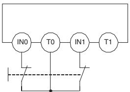 | Safety Inputs used as “Dual Channel input” with test output.Test output used as "Pulse Test Output". | |
Connect the switches between 24 V DC and IN0, IN1. 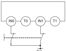 | Safety Inputs used as “Dual Channel input” without test output. | |
Safety Light Curtain 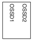 | Connect OSSD1 and OSSD2 to IN0 and IN1, respectively. 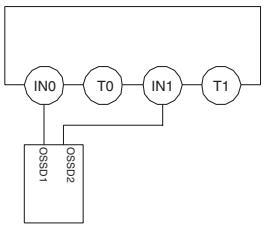 | Safety Inputs used as “Dual Channel input” without test output. |
8-2 Examples of Wiring for Each Application
8-2-1 Emergency Stop Switch Dual Channel Inputs with Manual Reset
An example of the wiring and configuration when using the DST1-ID12SL-1 is shown below.
Wiring
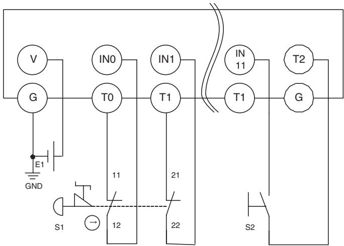
text_image
V IN0 IN1 IN T2 G T0 T1 T1 G E1 GND 11 21 S1 12 22 S2E1: 24-V DC Power Supply (S8□□)
S1: Emergency Stop Switch (A165E or A22E) (positive opening mechanism)
S2: Reset switch
Configuration
| Parameter group | Parameter name | Value | |
| Safety Input 0 | 0008 | Safety Input 0 Channel Mode | Test pulse from test output |
| 0009 | Safety Input 0 Test Source | Test Output 0 | |
| 0054 | Dual Channel Safety Input 0/1 Mode | Dual Channel Equivalent | |
| 0055 | Dual Channel Safety Input 0/1 Discrepancy Time | 100 x 10 ms | |
| Safety Input 1 | 0012 | Safety Input 1 Channel Mode | Test pulse from test output |
| 0013 | Safety Input 1 Test Source | Test Output 1 | |
| Safety Input 11 | 0052 | Safety Input 11 Channel Mode | Used as standard input |
| 0053 | Safety Input 11 Test Source | Not Used | |
| 0064 | Dual Channel Safety Input 10/11 Mode | Single Channel | |
| Test Output 0 | 0001 | Test Output 0 Mode | Pulse Test Output |
| Test Output 1 | 0002 | Test Output 1 Mode | Pulse Test Output |
| Test Output 2 | 0003 | Test Output 2 Mode | Power Supply Output |
8-2-2 Two-Hand Input
An example of the wiring and configuration when using the DST1-ID12SL-1 is shown below.
Wiring
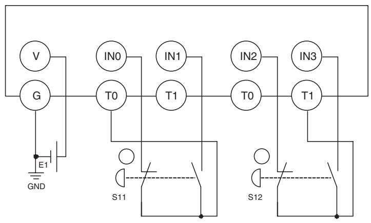
flowchart
graph TD
    V --> G
    G --> E1
    E1 --> GND
    GND --> S11
    S11 --> T0
    T0 --> IN0
    T0 --> T1
    T1 --> IN1
    T1 --> T0
    T0 --> IN2
    T0 --> T1
    T1 --> IN3
    T1 --> S12
    S12 --> T1
E1: 24-V DC Power Supply (S8□□)
S11,S12: Two-hand control switches
Configuration
| Parameter Group | Parameter Name | Value | |
| Safety Input 0 | 0008 | Safety Input 0 Channel Mode | Test pulse from test output |
| 0009 | Safety Input 0 Test Source | Test Output 0 | |
| 0054 | Dual Channel Safety Input 0/1 Mode | Dual Channel Complementary | |
| 0055 | Dual Channel Safety Input 0/1 Discrepancy Time | 100 x 10 ms | |
| Safety Input 1 | 0012 | Safety Input 1 Channel Mode | Test pulse from test output |
| 0013 | Safety Input 1 Test Source | Test Output 0 | |
| Safety Input 2 | 0016 | Safety Input 2 Channel Mode | Test pulse from test output |
| 0017 | Safety Input 2 Test Source | Test Output 1 | |
| 0056 | Dual Channel Safety Input 2/3 Mode | Dual Channel Complementary | |
| 0057 | Dual Channel Safety Input 2/3 Discrepancy Time | 100 x 10 ms | |
| Safety Input 3 | 0020 | Safety Input 3 Channel Mode | Test pulse from test output |
| 0021 | Safety Input 3 Test Source | Test Output 1 | |
| Test Output 0 | 0001 | Test Output 0 Mode | Pulse Test Output |
| Test Output 1 | 0002 | Test Output 1 Mode | Pulse Test Output |
8-2-3 User Mode Switch Input
An example of the wiring and configuration when using the DST1-ID12SL-1 is shown below.
Wiring
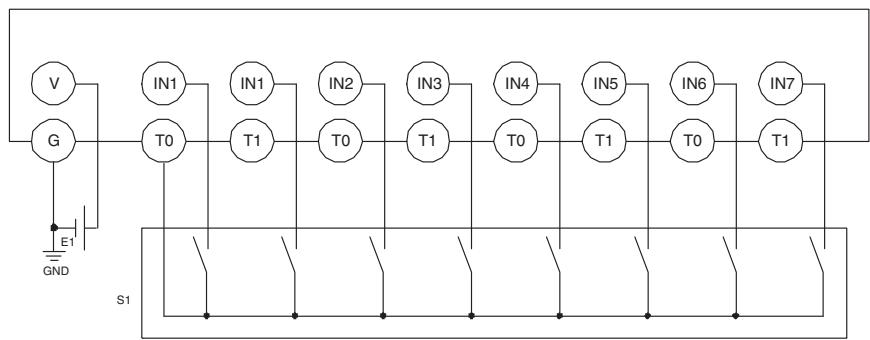
flowchart
graph TD
    V --> G
    G --> E1
    E1 --> GND
    T0 --> IN1
    T0 --> IN2
    T0 --> IN3
    T0 --> IN4
    T0 --> IN5
    T0 --> IN6
    T0 --> IN7
    IN1 --> T1
    IN2 --> T0
    IN3 --> T1
    IN4 --> T0
    IN5 --> T1
    IN6 --> T0
    IN7 --> T1
    S1 --> Ground
    E1 -.-> Ground
    GND -.-> Ground
E1: 24-V DC Power Supply (S8□□)
S1: User mode switch
Configuration
| Parameter group | Parameter name | Value | |
| Safety Input 0 | 0008 | Safety Input 0 Channel Mode | Test pulse from test output |
| 0009 | Safety Input 0 Test Source | Test Output 0 | |
| 0054 | Dual Channel Safety Input 0/1 Mode | Single Channel | |
| Safety Input 1 | 0012 | Safety Input 1 Channel Mode | Test pulse from test output |
| 0013 | Safety Input 1 Test Source | Test Output 0 | |
| Safety Input 2 | 0016 | Safety Input 2 Channel Mode | Test pulse from test output |
| 0017 | Safety Input 2 Test Source | Test Output 0 | |
| 0056 | Dual Channel Safety Input 2/3 Mode | Single Channel | |
| Safety Input 3 | 0020 | Safety Input 3 Channel Mode | Test pulse from test output |
| 0021 | Safety Input 3 Test Source | Test Output 0 | |
| Safety Input 4 | 0024 | Safety Input 4 Channel Mode | Test pulse from test output |
| 0025 | Safety Input 4 Test Source | Test Output 0 | |
| 0058 | Dual Channel Safety Input 4/5 Mode | Single Channel | |
| Safety Input 5 | 0028 | Safety Input 5 Channel Mode | Test pulse from test output |
| 0029 | Safety Input 5 Test Source | Test Output 0 | |
| Safety Input 6 | 0032 | Safety Input 6 Channel Mode | Test pulse from test output |
| 0033 | Safety Input 6 Test Source | Test Output 0 | |
| 0060 | Dual Channel Safety Input 6/7 Mode | Single Channel | |
| Safety Input 7 | 0036 | Safety Input 7 Channel Mode | Test pulse from test output |
| 0037 | Safety Input 7 Test Source | Test Output 0 | |
| Test Output 0 | 0001 | Test Output 0 Mode | Pulse Test Output |
8-2-4 Muting Lamp Output
An example of the wiring and configuration when using the DST1-ID12SL-1 is shown below.
Wiring
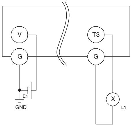
text_image
V G E1 GND T3 G X L1E1: 24-V DC Power Supply (S8□□)
L1: External muting lamp
Configuration
| Parameter group | Parameter name | Value | |
| Test Output 3 | 0004 | Test Output 3 Mode | Muting Lamp Output |
8-2-5 Limit Switch Dual Channel Inputs and a Manual Reset
An example of the wiring and configuration when using the DST1-ID12SL-1 is shown below.
Wiring
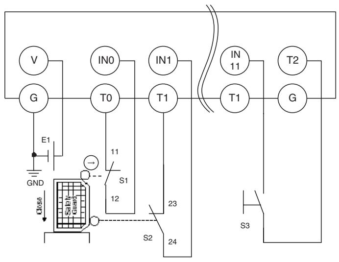
flowchart
graph TD
    V["Generator V"] --> G["Generator G"]
    G --> E1["Inductance E1"]
    E1 --> GND["GND"]
    GND --> Close["Close"]
    S1["S1"] -->|11| T0["T0"]
    S2["S2"] -->|12| T0
    T0 --> IN0["IN0"]
    T1["T1"] --> IN1["IN1"]
    T1 --> IN11["IN 11"]
    T1 --> T11["T1"]
    T11 --> T2["T2"]
    T2 --> G["G"]
    S3["S3"] -->|23| T1
    S2["S2"] -->|24| T1
    S1["S1"] -->|12| S2
    S2["S2"] -->|23| S1
E1: 24-V DC Power Supply (S8□□)
S1: Safety Limit Switch (D4D or D4B) (positive opening mechanism)
S2: Limit switch
S3: Reset switch
Configuration
| Parameter group | Parameter name | Value | |
| Safety Input 0 | 0008 | Safety Input 0 Channel Mode | Test pulse from test output |
| 0009 | Safety Input 0 Test Source | Test Output 0 | |
| 0054 | Dual Channel Safety Input 0/1 Mode | Dual Channel Equivalent | |
| 0055 | Dual Channel Safety Input 0/1 Discrepancy Time | 100 x 10 ms | |
| Safety Input 1 | 0012 | Safety Input 1 Channel Mode | Test pulse from test output |
| 0013 | Safety Input 1 Test Source | Test Output 1 | |
| Safety Input 11 | 0052 | Safety Input 11 Channel Mode | Used as standard input |
| 0053 | Safety Input 11 Test Source | Not Used | |
| 0064 | Dual Channel Safety Input 10/11 Mode | Single Channel | |
| Test Output 0 | 0001 | Test Output 0 Mode | Pulse Test Output |
| Test Output 1 | 0002 | Test Output 1 Mode | Pulse Test Output |
| Test Output 2 | 0003 | Test Output 2 Mode | Power Supply Output |
8-2-6 Safety Light Curtain Input
An example of the wiring and configuration when using the DST1-ID12SL-1 is shown below.
Wiring
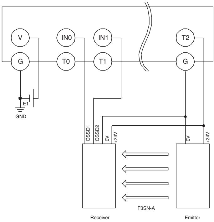
text_image
V G E1 GND IN0 T0 IN1 T1 T2 G OSSD1 OSSD2 0V +24V Receiver F3SN-A O5 +24V EmitterE1: 24-V DC Power Supply (S8□□)
F3SN-A: Safety Light Curtain
Configuration
| Parameter group | Parameter name | Value | |
| Safety Input 0 | 0008 | Safety Input 0 Channel Mode | Used as safety input |
| 0009 | Safety Input 0 Test Source | Not Used | |
| 0054 | Dual Channel Safety Input 0/1 Mode | Dual Channel Equivalent | |
| 0055 | Dual Channel Safety Input 0/1 Discrepancy Time | 100 x 10 ms | |
| Safety Input 1 | 0012 | Safety Input 1 Channel Mode | Used as safety input |
| 0013 | Safety Input 1 Test Source | Not Used | |
| Test Output 2 | 0003 | Test Output 2 Mode | Power Supply Output |
8-2-7 Semiconductor Outputs for Dual Channel Mode
An example of the wiring and configuration when using the DST1-MD16SL-1 is shown below.
Wiring
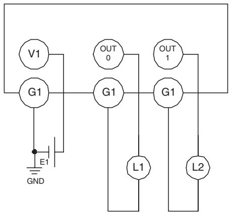
text_image
V1 G1 E1 GND OUT 0 G1 L1 OUT 1 G1 L2E1: 24-V DC Power Supply (S8□□)
L1, L2: Loads
Configuration
| Parameter Group | Parameter Name | Value | |
| Safety Output 0 | 0006 | Safety Output 0 Channel Mode | Safety Pulse Test |
| 0014 | Dual Channel Safety Output 0/1 Mode | Dual Channel | |
| Safety Output 1 | 0007 | Safety Output 1 Channel Mode | Safety Pulse Test |
8-2-8 Relay Outputs with Dual Channel Mode and EDM Input
An example of the wiring and configuration when using the DST1-MRD08SL-1 is shown below.
Wiring
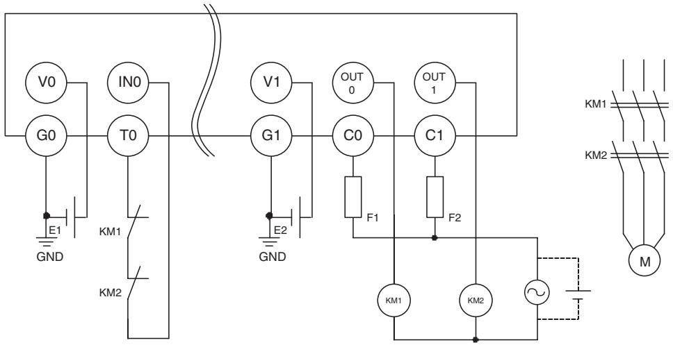
text_image
V0 IN0 G0 T0 E1 KM1 KM2 GND V1 OUT0 G1 E2 GND C0 OUT1 F1 C1 F2 KM1 KM2 M KM1 KM2E1, E2: 24-V DC Power Supply (S8□□)
KM1, KM2: Magnetic Contactors
M: 3-phase motor
F1, F2: Fuses
Configuration
| Parameter Group | Parameter Name | Value | |
| Safety Input 0 | 0015 | Safety Input 0 Channel Mode | Test pulse from test output |
| 0016 | Safety Input 0 Test Source | Test Output 0 | |
| 0029 | Dual Channel Safety Input 0/1 Mode | Single Channel | |
| Test Output 0 | 0001 | Test Output 0 Mode | Pulse Test Output |
| Safety Output 0 | 0006 | Safety Output 0 Channel Mode | Used |
| 0010 | Dual Channel Safety Output 0/1 Mode | Dual Channel | |
| Safety Output 1 | 0007 | Safety Output 1 Channel Mode | Used |
8-3 Logic Terminal Wiring Examples
8-3-1 Stopping Outputs by Using an Emergency Stop Switch or a Signal from a Safety Master
An example of the wiring and configuration when using the DST1-XD0808SL-1 is shown below.
Wiring
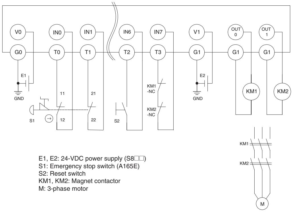
flowchart
graph TD
    subgraph Power Supply
        E1["EM"] --> GND["GND"]
        E2["EM"] --> S1["S1"]
        E2 --> S2["S2"]
        E2 --> KM1["KM1"]
        E2 --> KM2["KM2"]
        E2 --> KM1_M["M"]
    end

    subgraph Control Circuit
        S1 --> T0["T0"]
        T0 --> IN0["IN0"]
        IN0 --> V0["V0"]
        IN0 --> IN1["IN1"]
        IN1 --> T1["T1"]
        T1 --> IN6["IN6"]
        IN6 --> T2["T2"]
        T2 --> IN7["IN7"]
        IN7 --> T3["T3"]
        T3 --> KM1_NC["KM1-NC"]
        T3 --> KM2_NC["KM2-NC"]
        KM1_NC --> KM1_GND["GND"]
        KM2_NC --> KM1_GND
        KM1_GND --> OUT0["OUT0"]
        KM1_GND --> OUT1["OUT1"]
        KM1_GND --> KM2_GND["KM2"]
    end

    subgraph Motor Control Circuit
        KM1_NC --> KM2_GND
        KM1_GND --> KM1_GND
        KM1_GND --> KM2_GND
        KM1_GND --> KM2_GND
        KM1_GND --> KM1_M
        KM2_GND --> KM1_GND
        KM2_GND --> KM2_GND
    end

    style Power Supply fill:#f9f,stroke:#333
    style Control Circuit fill:#ccf,stroke:#333
Operation Chart
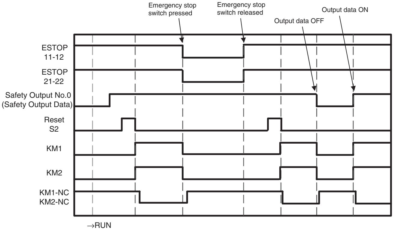
flowchart
graph TD
    A["ESTOP 11-12"] --> B["Emergency stop switch pressed"]
    C["ESTOP 21-22"] --> D["Emergency stop switch released"]
    E["Safety Output No.0 (Safety Output Data)"] --> F["Output data OFF"]
    G["Reset S2"] --> H["Reset S2"]
    I["KM1"] --> J["KM1"]
    K["KM2"] --> L["KM2"]
    M["KM1-NC KM2-NC"] --> N["KM1-NC KM2-NC"]
    style A fill:#f9f,stroke:#333
    style C fill:#f9f,stroke:#333
    style E fill:#f9f,stroke:#333
    style G fill:#f9f,stroke:#333
    style I fill:#f9f,stroke:#333
    style K fill:#f9f,stroke:#333
    style M fill:#f9f,stroke:#333
    style M fill:#ccf,stroke:#333
    style N fill:#ccf,stroke:#333
Configuration
| Port | Safety Input Parameter | |||||
| Channel Mode | Test Source | Off On Delay | On Off Delay | Dual Channel Mode | Discrepancy Time | |
| IN 0 | Test Pulse from test out | Test Output 0 | 0 ms | 0 ms | Dual Channel Equivalent | 500 ms |
| IN 1 | Test Pulse from test out | Test Output 1 | 0 ms | 0 ms | ||
| IN 6 | Test Pulse from test out | Test Output 2 | 0 ms | 0 ms | Single Channel | --- |
| IN 7 | Test Pulse from test out | Test Output 3 | 0 ms | 0 ms | Single Channel | --- |
| Port | Test Output Parameter |
| Output Mode | |
| T0 | Pulse Test Output |
| T1 | Pulse Test Output |
| T2 | Pulse Test Output |
| T3 | Pulse Test Output |
| Port | Safety Output Parameter | |||
| Channel Mode | Off On Delay | On Off Delay | Dual Channel Mode | |
| OUT 0 | Safety Pulse Test | 0 ms | 0 ms | Dual Channel |
| OUT 1 | Safety Pulse Test | 0 ms | 0 ms | |
| Input | Input Condition | Reset | |||
| [IN0/1]EMO NCEMO NC |  Off On Delay:0 msOn Off Delay:0 ms Off On Delay:0 msOn Off Delay:0 ms |  Reset Condition:IN6 Reset Low-High-Low Reset Condition:IN6 Reset Low-High-Low | [Jump0]EMO NC | ||
| [IN6]Reset | |||||
| Off On Delay:0 msOn Off Delay:0 ms | |||||
| [IN7]Feedback(00) | |||||
| Off On Delay:0 msOn Off Delay:0 ms | |||||
| Output Condition | Welding Check(EDM) | Output | |
 AND Condition :[Jump0] EMO NCRemote I/O AND Condition :[Jump0] EMO NCRemote I/O | ...  Feedback :IN7 Feedback(00) Feedback :IN7 Feedback(00) | Off On Delay :0 msOn Off Delay : | [OUT0/1]Safety RelaySafety Relay |
Appendix
Appendix 1: DeviceNet Explicit Messages
DeviceNet explicit messages sent from the Master Unit to the DST1-series Terminals can be used to read or write any parameter of a specified Terminal. The DST1-series Terminal processes a command sent from the Master Unit and then returns a response.
A-1-1 Basic Format of Explicit Messages
The basic format of each command and response is shown below.
Command Block
| Destination node address | Service code | Class ID | Instance ID | Attribute ID | Data |
Destination Node Address
The node address of the Unit that is sending the explicit message is specified with on hexadecimal byte.
Service Code, Class ID, Instance ID, and Attribute ID
The parameters used for specifying the command, processing object, and processing content.
Note The number of bytes designated for the class ID, instance ID, and attribute ID depend on the Master Unit. When sent from an OMRON DeviceNet Master, the class ID and instance ID are 2 bytes (4 digits) each, and the attribute ID is 1 byte (2 digits).
Data
Data is not required when a read command is used.
Response Block
Normal Response Block
| Number of bytes received | Source node address | Service code | Data |
Error Response Block
| Number of bytes received0004 hex (fixed) | Source nodeaddress | Service code | Error code |
Number of Bytes Received
The number of bytes received from the source node address is returned in hexadecimal. When an error response is returned for an explicit message, the number of bytes is always 0004 hex.
Source Node Address
The node address of the node from which the command was sent is returned in hexadecimal.
Service Code
For normal completions, the service code specified in the command with the leftmost bit turned ON is stored as shown in the following table.
| Function | Command service code | Response service code |
| Read data | 10 hex | 90 hex |
| Write data | 0E hex | 8E hex |
| Reset | 05 hex | 85 hex |
| Save | 16 hex | 96 hex |
When an error response is returned for an explicit message, the value is always 94 hex.
Data
Read data is included only when a read command is executed.
Error Code
The explicit message error code. For details, refer to the list of error codes in the following table.
Error Codes
| Code | Error name | Cause |
| 08FF | Service not supported | The service code is incorrect. |
| 09FF | Invalid attribute value | The specified attribute value is not supported.The data written was outside the valid range. |
| 16FF | Object does not exist | The specified Instance ID is not supported. |
| 15FF | Too much data | The data is larger than the specified size. |
| 13FF | Not enough data | The data is smaller than the specified size. |
| 0CFF | Object state conflict | The specified command cannot be executed due to an internal error. |
| 20FF | Invalid parameter | The specified operation command data is not supported. |
| 0EFF | Attribute not settable | An attribute ID supported only for reading has been executed for a write service code. |
| 10FF | Device state conflict | The specified command cannot be executed due to an internal hardware error. |
| 14FF | Attribute not supported | The specified attribute is not supported. |
| 19FF | Store operation failure | The data cannot be stored in memory. |
| 2AFF | Group 2 only server general failure | The specified command or attribute is not supported or the attribute was not set. |
A-1-2 Explicit Messages
Reading General Status
| Explicit message | Read/write | Function | Command | Response | ||||
| Service code | Class ID | Instance ID | Attribute ID | Data size | ||||
| General Status Read | Read | Reads the specified slave's status flags (8 bits) | 0E hex | 95 hex | 01 hex | 65 hex | - | 1 byte |
Setting and Monitoring the Unit Conduction Time
| Explicit message | Read/write | Function | Command | Response | ||||
| Service Code | Class ID | Instance ID | Attribute ID | Data size | ||||
| Unit Maintenance Set Value | Read | Reads the set value for the Unit Conduction Time (unit: 0.1 h). | 0E hex | 95 hex | 01 hex | 73 hex | - | 4 bytes0000 0000 to FFFF FFFF hex(0 to 4,294,967,295) |
| Write | Writes the set value for the Unit Conduction Time (unit: 0.1 h). | 10 hex | 95 hex | 01 hex | 73 hex | 4 bytes0000 0000 to FFFF FFFF hex(0 to 4,294,967,295) | ||
| Unit Maintenance Present Value | Read | Reads the present value for the Unit Conduction Time (unit: 0.1 h). | 0E hex | 95 hex | 01 hex | 71 hex | 4 bytes0000 0000 to FFFF FFFF hex(0 to 4,294,967,295) | |
| Unit Maintenance Flag | Read | Reads the monitor status of Unit Conduction Time. | 0E hex | 95 hex | 01 hex | 72 hex | 1 byte00 hex: Within range01 hex: Over range (over the monitor value) | |
Setting and Monitoring a Safety Input
| Explicit message | Read/write | Function | Command | Response | ||||
| Service Code | Class ID | Instance ID | Attribute ID | Data size | ||||
| Terminal Maintenance Information Monitor Mode | Read | Reads the monitor mode for maintenance information of the input (1 to 12) specified by the instance ID. | 0E hex | 3D hex | 01 to 0C hex | 65 hex | 1 byte00 hex: Total ON time mode01 hex: Contact operation counter mode | |
| Write | Writes the monitor mode for maintenance information of the input (1 to 12) specified by the instance ID. | 10 hex | 3D hex | 01 to 0C hex | 65 hex | 1 byte00 hex: Total ON time mode01 hex: Contact operation counter mode | ||
| Input Set Value for Total ON Time or Contact Operation Counter | Read | Reads the set value for the total ON time (unit: s) or number of contact operations (unit: operations) of the input (1 to 12) specified by the instance ID. | 0E hex | 3D hex | 01 to 0C hex | 68 hex | 4 bytes0000 0000 to FFFF FFFF hex(0 to 4,294,967,295) | |
| Write | Writes the set value for the total ON time (unit: s) or number of contact operations (unit: operations) of the input (1 to 12) specified by the instance ID. | 10 hex | 3D hex | 01 to 0C hex | 68 hex | 4 bytes0000 0000 to FFFF FFFF hex(0 to 4,294,967,295) | ||
| Input Total ON Time or Contact Operation Counter Read | Read | Reads the set value for the total ON time (unit: s) or number of contact operations (unit: operations) of the input (1 to 12) specified by the instance ID. | 0E hex | 3D hex | 01 to 0C hex | 66 hex | 4 bytes0000 0000 to FFFF FFFF hex(0 to 4,294,967,295) | |
| Input Total ON Time or Contact Operation Counter Reset | Reset | Resets the total ON time or number of contact operations (unit: operations) for time input (1 to 12) specified by the instance ID. | 05 hex | 3D hex | 01 to 0C hex | 66 hex | ||
| Input Monitor Status for Total ON Time or Contact Operation Counter Read | Read | Reads the set value for the total ON time (unit: s) or number of contact operations (unit: operations) of the input (1 to 12) specified by the instance ID. | 0E hex | 3D hex | 01 to 0C hex | 67 hex | 1 byte00 hex: Within range01 hex: Over range (over the monitor value) | |
| Safety Input Cause of Error Information Read | Read | Reads the cause for the normal flag (1 to 12) specified by the Instance ID turning OFF. | 0E hex | 3D hex | 01 to 0C hex | 6E hex | 0: No error01 hex: Configuration invalid02 hex: External wiring error03 hex: Internal input failure04 hex: Two-input logic discrepancy05 hex: Error in the other dual channel input | |
Setting and Monitoring the Safety Output Point
| Explicit message | Read/write | Function | Command | Response | ||||
| Service Code | Class ID | Instance ID | Attribute ID | Data size | ||||
| Terminal Maintenance Information Monitor Mode Read | Read | Reads the monitor mode for maintenance information of the output (1 to 8) specified by the instance ID. | 0E hex | 3B hex | 01 to 08 hex | 65 hex | - | 1 byte00 hex: Total ON time mode01 hex: Contact operation counter mode |
| Write | Writes the monitor mode for maintenance information of the output (1 to 8) specified by the instance ID. | 10 hex | 3B hex | 01 to 08 hex | 65 hex | 1 byte00 hex: Total ON time mode01 hex: Contact operation counter mode | - | |
| Output Set Value for Total ON Time or Contact Operation | Read | Reads the set value for the total ON time (unit: s) or number of contact operations (unit: operations) of the output (1 to 8) specified by the instance ID. | 0E hex | 3B hex | 01 to 08 hex | 68 hex | - | 4 bytes0000 0000 to FFFF FFFF hex (0 to 4,294,967,295) |
| Write | Writes the set value for the total ON time (unit: s) or number of contact operations (unit: operations) of the output (1 to 8) specified by the instance ID. | 10 hex | 3B hex | 01 to 08 hex | 68 hex | 4 bytes0000 0000 to FFFF FFFF hex (0 to 4,294,967,295) | - | |
| Output Total ON Time or Contact Operation Counter Read | Read | Reads the set value for the total ON time (unit: s) or number of contact operations (unit: operations) of the output (1 to 8) specified by the instance ID. | 0E hex | 3B hex | 01 to 08 hex | 66 hex | - | 4 bytes0000 0000 to FFFF FFFF hex (0 to 4,294,967,295) |
| Output Total ON Time or Contact Operation Counter Reset | Reset | Resets the total ON time or number of contact operations for time output (1 to 8) specified by the instance ID. | 05 hex | 3B hex | 01 to 08 hex | 66 hex | ||
| Output Monitor Status for Total ON Time or Contact Operation Counter Read | Read | Reads the set value for the total ON time or number of contact operations of the output (1 to 8) specified by the instance ID. | 0E hex | 3B hex | 01 to 08 hex | 67 hex | - | 1 byte00 hex: Within range01 hex: Over range (over the monitor value) |
| Safety Output Cause of Error Information Read | Read | Reads the cause for the normal flag (1 to 8) specified by the Instance ID turning OFF. | 0E hex | 3B hex | 01 to 08 hex | 6E hex | 0: No error01 hex: Configuration invalid02 hex: Overcurrent detected03 hex: Short-circuit detected04 hex: Output ON error05 hex: Error in the other dual channel output06 hex: Internal relay relevant circuit error07 hex: Relay failure08 hex: Dual channel violation09 hex: Cross connection detected0A hex: EDM error | |
Setting and Monitoring the Test Output Point
| Explicit message | Read/write | Function | Command | Response | ||||
| Service Code | Class ID | Instance ID | Attribute ID | Data size | ||||
| Terminal Maintenance Information Monitor Mode Read | Read | Reads the monitor mode for maintenance information of the output (1 to 4) specified by the instance ID. | 0E hex | 09 hex | 01 to 04 hex | 65 hex | - | 1 byte00 hex: Total ON time mode01 hex: Contact operation counter mode |
| Write | Writes the monitor mode for maintenance information of the output (1 to 4) specified by the instance ID | 10 hex | 09 hex | 01 to 04 hex | 65 hex | 1 byte00 hex: Total ON time mode01 hex: Contact operation counter mode | - | |
| Output Set Value for Total On Time or Contact Operation | Read | Reads the set value for the total ON time (unit: s) or number of contact operations (unit: operations) of the output (1 to 4) specified by the instance ID. | 0E hex | 09 hex | 01 to 04 hex | 68 hex | - | 4 bytes0000 0000 to FFFF FFFF hex(0 to 4,294,967,295) |
| Write | Writes the set value for the total ON time (unit: s) or number of contact operations (unit: operations) of the output (1 to 4) specified by the instance ID. | 10 hex | 09 hex | 01 to 04 hex | 68 hex | 4 bytes0000 0000 to FFFF FFFF hex(0 to 4,294,967,295) | - | |
| Output Total ON Time or Contact Operation Counter Read | Read | Reads the set value for the total ON time (unit: s) or number of contact operations (unit: operations) of the output (1 to 4) specified by the instance ID. | 0E hex | 09 hex | 01 to 04 hex | 66 hex | - | 4 bytes0000 0000 to FFFF FFFF hex(0 to 4,294,967,295) |
| Output Total ON Time or Contact Operation Counter Reset | Reset | Resets the total ON time or number of contact operations for time output (1 to 4) specified by the instance ID. | 05 hex | 09 hex | 01 to 04 hex | 66 hex | ||
| Output Monitor Status for Total ON Time or Contact Operation Counter Read | Read | Reads the set value for the total ON time or number of contact operations (unit: operations) of the output (1 to 4) specified by the instance ID. | 0E hex | 09 hex | 01 to 04 hex | 67 hex | - | 1 byte00 hex: Within range01 hex: Over range (over the monitor value) |
| Safety Output Cause of Error Information Read | Read | Reads the cause for the normal flag (1 to 8) specified by the Instance ID turning OFF. | 0E hex | 09 hex | 01 to 04 hex | 76 hex | 0 = No error01 hex: Configuration invalid02 hex: Over-load detected05 hex: Output ON error06 hex: Current limit detection | |
Setting and Monitoring Operation Time
| Explicit message | Read/write | Function | Command | Response Data size | ||||
| Service Code | Class ID | Instance ID | Attribute ID | Data size | ||||
| Set Value for Operation Time Monitor | Read | Reads the monitor value for the time (unit: ms) from when the output (1 to 8) specified by the instance ID turns ON until the corresponding input turns ON. | 0E hex | 97 hex | 01 to 08 hex | 67 hex | - | 2 bytes0000 to FFFF hex(0 to 65535) |
| Write | Writes the monitor value for the time (unit: ms) from when the output (1 to 8) specified by the instance ID turns ON until the corresponding input turns ON. | 10 hex | 97 hex | 01 to 08 hex | 67 hex | 2 bytes0000 to FFFF hex(0 to 65535) | ||
| Present Value for Operation Time Monitor | Read | Reads the present value for the time (unit: ms) from when the output (1 to 8) specified by the instance ID turns ON until the corresponding input turns ON. | 0E hex | 97 hex | 01 to 08 hex | 65 hex | - | 2 bytes0000 to FFFF hex(0 to 65535) |
| Monitor Status Value for Operation Time Monitor Read | Read | Reads the monitor status for the time (unit: ms) from when the output (1 to 8) specified by the instance ID turns ON until the corresponding input turns ON. | 0E hex | 97 hex | 01 to 08 hex | 66 hex | - | 1 byte00 hex: Within range01 hex: Over range (over the monitor value) |
Setting Hold/Clear for Communications Errors (Test Output)
| Explicitmessage | Read/write | Function | Command | Response | ||||
| ServiceCode | ClassID | InstanceID | AttributeID | Data size | ||||
| Setting for Output Status (Hold or Clear) after Communications Error | Read | Reads whether hold or clear is set as the output status after a communications error for the output (1 to 4) specified by the instance ID. The setting can be read for a specified number of points. | 0E hex | 09 hex | 01 to 04 hex | 05 hex | - | 1 byte00 hex: Clear01 hex: Hold |
| Setting for Output Status (Hold or Clear) after Communications Error | Write | Sets either hold or clear as the output status after a communications error for an output (1 to 4) specified by the instance ID. The setting can be read for a specified number of points. | 10 hex | 09 hex | 01 to 04 hex | 05 hex | 1 byte00 hex: Clear01 hex: Hold | |
Note The default setting is for all outputs to be cleared (0).
Writing Maintenance Information
| Explicit message | Read/write | Function | Command | Response | ||||
| Service Code | Class ID | Instance ID | Attribute ID | Data size | ||||
| Maintenance Counter Save | Save | Records the maintenance counter in the Slave's memory | 16 hex | 95 hex | 01 hex | - | - | - |
A-1-3 Using Explicit Messages
The following example shows how to use explicit messages with the DST1-series Safety I/O Terminals using a CS1W-DRM21 DeviceNet Unit (Master).
Example: Reading the Monitor Status for the Operation Time Monitor
Example Conditions
DeviceNet Unit node address: 05
Unit number: 0
Unit address: FE hex (or 10 hex)
DST1 node address: 11
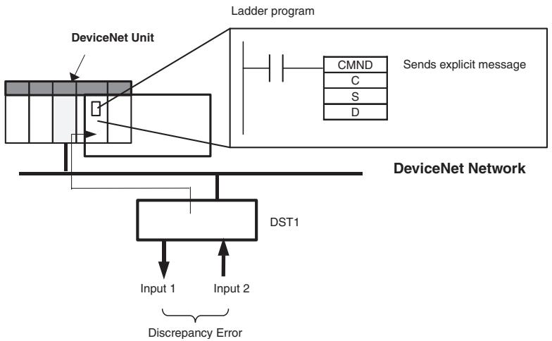
flowchart
graph TD
    A["DeviceNet Unit"] --> B["Ladder program"]
    B --> C["CMND"]
    B --> D["C"]
    B --> E["S"]
    B --> F["D"]
    C --> G["Sends explicit message"]
    D --> G
    E --> G
    F --> G
    G --> H["DeviceNet Network"]
    H --> I["DST1"]
    I --> J["Input 1"]
    I --> K["Input 2"]
    I --> L["Discrepancy Error"]
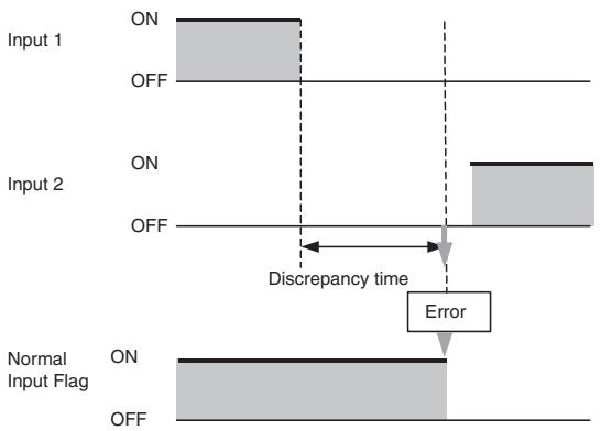
flowchart
graph TD
    A["Input 1 ON"] --> B["Off"]
    C["Input 2 ON"] --> D["Off"]
    E["Normal Input Flag ON"] --> F["Off"]
    G["Error"] --> H["Discrepancy time"]
    style A fill:#f9f,stroke:#333
    style C fill:#f9f,stroke:#333
    style E fill:#f9f,stroke:#333
    style G fill:#f9f,stroke:#333
    style B fill:#ccf,stroke:#333
    style D fill:#ccf,stroke:#333
    style F fill:#ccf,stroke:#333
    style H fill:#ccf,stroke:#333
Command Details
• [CMND S D C]
S: D01000
D (first response word): D02000
C: D00000
Contents of S
| Address | Contents | Meaning |
| D01000 | 2801 hex | Command code |
| D01001 | 0B0E hex | DST1 node address: 11Service code: 0E hex |
| D01002 | 003D hex | Class ID: 003D hex |
| D01003 | 0001 hex | Instance ID: 0001 hex |
| D01004 | 6E** hex | Attribute ID: 6E□□ hex (Set any value for the blank boxes.) |
Contents of C
| Address | Contents | Meaning |
| D00000 | 0009 hex | Number of bytes of command data |
| D00001 | 0009 hex | Number of bytes of response data |
| D00002 | 0000 hex | Destination DeviceNet Unit network address: 0 |
| D00003 | 05FE hex | Destination DeviceNet Unit node address: 5Destination DeviceNet Unit address: FE hex (or 10 hex) |
| D00004 | 0000 hex | Response requiredCommunications port number: 0Number of retries: 0 |
| D00005 | 003C hex | Response monitoring time: 6 s |
Response
Contents of D
| Address | Contents | Meaning |
| D02000 | 2801 hex | |
| D02001 | 0000 hex | |
| D02002 | 0003 hex | |
| D02003 | 0B8E hex | Response source node address: 11 (0B hex)Normal completion: 8E hex |
| D02004 | 0400 hex | Safety input cause of error information:0004Discrepancy Error |
Appendix 2: Calculated Values of PFD and PFH
Calculated values of PFD and PFH of the DST1-series Safety I/O Terminals are given in the following tables. These values must be calculated for the overall devices within the system to comply with the SIL level required for application.
A-2-1 Calculated PFD Values
| Model | Proof test interval (years) | PFD |
| DST1-ID12SL-1 | 0.25 | 2.21E-07 |
| 0.5 | 4.39E-07 | |
| 1 | 8.76E-07 | |
| 2 | 1.76E-06 | |
| DST1-MD16SL-1 | 0.25 | 2.22E-07 |
| 0.5 | 4.40E-07 | |
| 1 | 8.77E-07 | |
| 2 | 1.76E-06 | |
| DST1-MRD08SL-1 | 0.25 | 4.70E-06 |
| 0.5 | 9.54E-06 | |
| DST1-XD0808SL-1 | 0.25 | 2.22E-07 |
| 0.5 | 4.40E-07 | |
| 1 | 8.77E-07 | |
| 2 | 1.76E-06 |
IMPORTANT The proof test interval of the DST1-MRD08SL-1 must not exceed 0.5 years because the maintenance interval for the relay contacts must not exceed a period of 6 month to satisfy safety category 4 in accordance with EN 954-1.
A-2-2 Calculated PFH Values
| Model | PFH |
| DST1-ID12SL-1 | 2.00E-10 |
| DST1-MD16SL-1 | 2.00E-10 |
| DST1-MRD08SL-1 | 4.20E-09 |
| DST1-XD0808SL-1 | 2.00E-10 |
Index
A
applications
precautions, xxi
C
cleaning, 86
communications connector, 26
configuration, 27
configuration lock indicator, 56
configuration status, 56
current consumption, 54
D
DeviceNet communications
connector, 26
specifications, 54
DeviceNet explicit messages, 103
DeviceNet Safety
protocol, 2
dimensions
DST1-ID12SL-1, 62
DST1-MD16SL-1, 66
DST1-MRD08SL-1, 71
DST1-XD0808SL-1, 75
discrepancy time, 11
DST1-ID12SL-1
dimensions, 62
internalcircuits,61
nomenclature, 60
safety input specifications, 60
terminal arrangement, 61
test output specifications, 60
DST1-MD16SL-1
dimensions, 66
internalcircuits,64
nomenclature, 64
safety input specifications, 63
safety output specifications, 63
terminal arrangement, 65
test output specifications, 63
DST1-MRD08SL-1
dimensions, 71
internalcircuits,68
nomenclature, 68
safety input specifications, 67
safety output specifications, 67
terminal arrangement, 68
test output specifications, 67
DST1-XD0808SL-1
dimensions, 75
internalcircuits,73
nomenclature, 72
safety input specifications, 72
safety output specifications, 72
terminal arrangement, 73
test output specifications, 72
dual channel mode, 11, 15
complementary, 14
equivalent, 13
relay outputs, 98
semiconductor outputs, 97
E
error codes
list, 104
error history, 84
error processing
indicators, 80
error recovery, 14, 16
explicit messages, 103
application examples, 114
list, 105
F
features, 3
ferrules, 24
list of models, 25
functions
password protection, 9
safety, 9
safety inputs, 7
safety outputs, 15
self-diagnosis, 9
test outputs, 8
G
general parameters, 31
glossary, xxii
I
I/O assembly data, 43
I/O cables, 24
I/O data, 38
I/O indicators, 57
I/O power supply indicators, 57
I/O status data, 16
IN PWR indicator, 57
indicators, 56
error processing, 80
inspection, 86
installation, 23
L
Limit Switch
with dual channel inputs, 95
LOCK indicator, 56
M
maintenance, 86
manual reset, 91, 95
MS indicator, 56
muting lamp output, 94
N
Network Configurator, 27
node address, 27
nomenclature
DST1-ID12SL-1, 60
DST1-MD16SL-1, 64
DST1-MRD08SL-1, 68
DST1-XD0808SL-1, 72
NS indicator, 56
O
OFF delay, 15
ON delay, 15
operating environment
precautions, xix
operation time parameters, 34
OUT PWR indicator, 57
P
parameters
general, 31
operation time, 34
safety input, 32
safety output, 34
test output, 33
password protection, 9
PFD
calculated values, 116
PFH
calculated values, 116
precautions
applications, xxi
general, xvi
operating environment, xix
replacing the DST1, 87
safety precautions, xviii
R
regulations, xxi
relay outputs
dual channel mode, 98
remote I/O allocations, 37
replacing the DST1, 87
S
safety functions, 9
Safety I/O Terminals, 2
with relay outputs, 67
safety input parameters, 32
safety input specifications, 63
DST1-ID12SL-1, 60
DST1-MRD08SL-1, 67
DST1-XD0808SL-1, 72
safety input terminals, 60
safety inputs, 7, 10
errors, 81
Safety Light Curtain input, 96
Safety Network Controller, 2
safety output parameters, 34, 36
safety output specifications
DST1-MD16SL-1, 63
DST1-MRD08SL-1, 67
DST1-XD0808SL-1, 72
relay outputs, 67
semiconductor outputs, 63
safety outputs, 15
errors, 83
safety precautions, xviii
self-diagnosis functions, 9
semiconductor outputs
dual channel mode, 97
specifications
common, 54
current consumption, 54
DeviceNet communications, 54
safety inputs, 60, 63, 67
test outputs, 60, 63, 67
weight, 54
standard models, 5
standards, xxi
T
terminal arrangement
DST1-ID12SL-1, 61
DST1-MD16SL-1, 65
DST1-MRD08SL-1, 68
DST1-XD0808SL-1, 73
test output parameters, 33
test output specifications
DST1-ID12SL-1, 60
DST1-MD16SL-1, 63
DST1-MRD08SL-1, 67
DST1-XD0808SL-1, 72
test outputs, 8
errors, 82
troubleshooting, 81
two-hand input, 92
U
user mode switch input, 93
W
weight, 54
wiring
examples, 91
input devices, 90
Revision History
The manual revision is indicated at the end of the Cat. No. printed at the lower left of back cover of the manual.
Cat. No. Z904-E1-04
Revision code
The following table outlines the changes made to the manual during each revision. Page numbers refer to the previous version.
| Revision code | Date | Revised content |
| 1 | April 2005 | First edition |
| 02 | February 2006 | Page 9:Precautions added.Pages 9 and 5-12:Information added on isolating transformers.Pages 3-7 and 3-8:Information added on I/O data supported by Safety I/O Terminals.Page 5-9:Changes made to safety output specifications.Page 6-2:Changes made to indicators and error processing table.Pages 6-3 to 6-5:Changes made to troubleshooting tables.Pages 6-6 and 6-7:Changes made to error history table. |
| 03 | June 2007 | Revised to add information on DST-XD0808SL-1 and corrected mistakes. |
| 04 | March 2008 | Page xx:Added precaution.Page xxi:Updated regulations and standards and removed note.Page 7:Changed definition of “contact operation counters.”Page 17:Added new material on DST-XD0808SL-1 and parameters that can be set and deleted previous material.Page 41:Added crimping tool model.Page 53:Changed “SAFE” and “NON-SAFE” designations in table.Pages 55 to 58:Changed description of default values.Pages 77, 80, 84, and 89:Changed “DRAIN” to “Shield” in circuit diagrams.Page 83:Removed specification for the rated load for an inductive load.Page 94:Added information for the DST-XD0808SL-1.Pages 97 to 99:Changed error names and responses. |