
A165W - Rotary switch OMRON - Free user manual and instructions
Find the device manual for free A165W OMRON in PDF.
User questions about A165W OMRON
0 question about this device. Answer the ones you know or ask your own.
Ask a new question about this device
Download the instructions for your Rotary switch in PDF format for free! Find your manual A165W - OMRON and take your electronic device back in hand. On this page are published all the documents necessary for the use of your device. A165W by OMRON.
USER MANUAL A165W OMRON
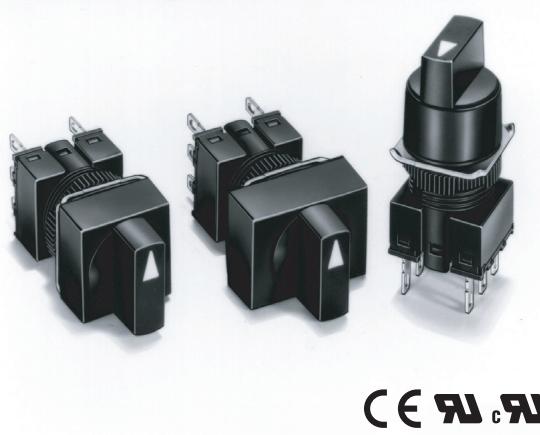
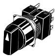
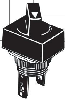
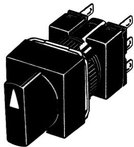
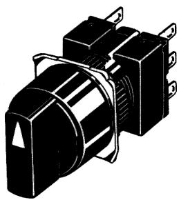
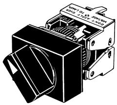
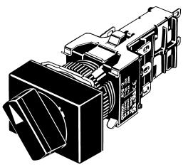
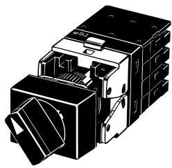
Knob-type Selector Switch
A165S/W
Mounting Aperture of 16 mm
- Modular construction
Oil-resistant IP65 models - UL and cUL approved.
- Conforms to EN60947-5-1, IEC947-5-1
- Short mounting depth, less than 28.5 mm below panel
- Wide range of switching capacity from standard to microload
- Lighted and non-lighted models
2 and 3-notch models - Manual and automatic reset models
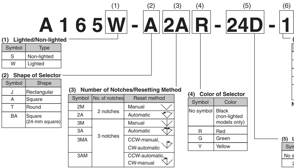
Model Number Structure
■ Model Number Legend
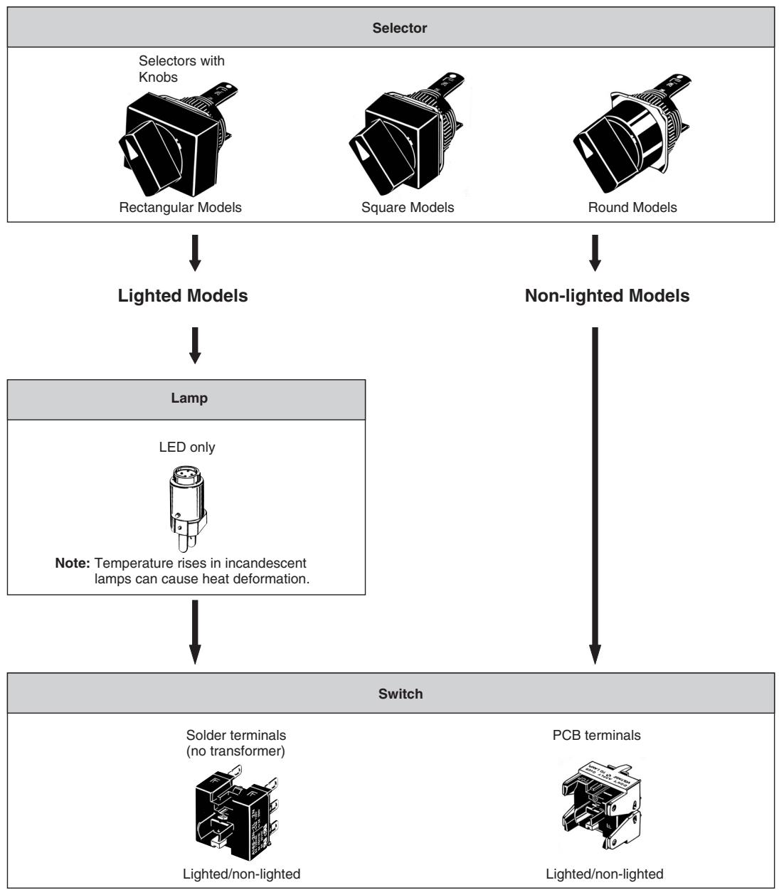
Completely Assembled
The model numbers used to order sets of Units are illustrated below. One set comprises the Selector, Lamp (lighted models only), and Switch.
(6) Contact Configuration
| Symbol | Type | Terminal |
| 1 | SPDT | Solder terminal |
| 2 | DPDT | |
| 1P | SPDT | PCB terminal |
| 2P | DPDT | |
| 2S | DPDT | Screw-Less Clamp |
Note: 1. Only DPDT contacts are available with 3-notch models and Scraw-Lee Clamp models.
2. PCB terminals are available only with 2-notch models.
(5) Light Source
| Symbol | Type |
| No symbol | Non-lighted |
| 24D | 24-V LED |
Voltage Reduction Unit (24-V Built-in LED)
| Symbol | Type | Operating voltage | Rated voltage |
| T1 | LED | 90 to 121 VAC/VDC | 110 VAC/VDC |
| T2 | 180 to 242 VAC/VDC | 220 VAC/VDC |
Note: 1. Solder terminals are only available with 100-V models.
2. The Voltage Reduction Unit is not available for models with PCB terminals.
Subassembled
1. Selector
A165□-□□□
1 2 3 4
- Lighted/Non-lighted
S: Non-lighted
W: Lighted
- Flange Shape
J: Rectangular
A: Square
T: Round
BA: Square (24-mm square)
- Number of Notches/Reset Method
2M: 2 notches/Manual
2A: 2 notches/Automatic
3M: 3 notches/Manual
3A: 3 notches/Mixed-operation
3MA: 3 notches
3AM: 3 notches
2. Switch (Same as for Key-type Selector Switches)
A16S-□-□□
1 2 3 4
- Number of Notches
2N: 2 notches
3N: 3 notches
- Contacts
1: SPDT
2: DPDT
3. Lamp
A16-□□
12
- Operating Voltage (Rated Voltage) LED
5DS: 5 VDC (5 VDC)
12DS:12 VDC (12 VDC)
24DS:24 VDC (24 VDC)
- Illumination Color
None: Black (Non-lighted models only)
R: Red
G: Green
Y: Yellow
- Lighted/Non-lighted
None: Non-lighted
L: Lighted
- Terminals
None: Solder terminals (tab terminals #110)
- Illumination Color
R: Red (LED)
G: Green (LED)
Y: Yellow (LED)
■ List of Models
Ordering as a Set
The model numbers used to order sets of Units are given in the following tables. One set comprises the Selector, Lamp (lighted models only), and Switch.
Solder Terminals
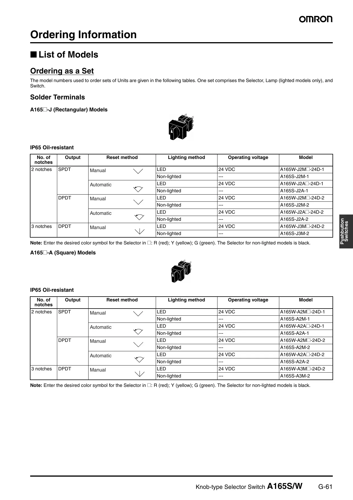
A165□-J (Rectangular) Models
IP65 Oil-resistant
A165□-A (Square) Models
| No. of notches | Output | Reset method | Lighting method | Operating voltage | Model |
| 2 notches | SPDT | Manual | LED | 24 VDC | A165W-J2M□-24D-1 |
| Non-lighted | --- | A165S-J2M-1 | |||
| Automatic | LED | 24 VDC | A165W-J2A□-24D-1 | ||
| Non-lighted | --- | A165S-J2A-1 | |||
| DPDT | Manual | LED | 24 VDC | A165W-J2M□-24D-2 | |
| Non-lighted | --- | A165S-J2M-2 | |||
| Automatic | LED | 24 VDC | A165W-J2A□-24D-2 | ||
| Non-lighted | --- | A165S-J2A-2 | |||
| 3 notches | DPDT | Manual | LED | 24 VDC | A165W-J3M□-24D-2 |
| Non-lighted | --- | A165S-J3M-2 |
Note: Enter the desired color symbol for the Selector in : R (red); Y (yellow); G (green). The Selector for non-lighted models is black.
IP65 Oil-resistant
| No. of notches | Output | Reset method | Lighting method | Operating voltage | Model |
| 2 notches | SPDT | Manual | LED | 24 VDC | A165W-A2M□-24D-1 |
| Non-lighted | --- | A165S-A2M-1 | |||
| Automatic | LED | 24 VDC | A165W-A2A□-24D-1 | ||
| Non-lighted | --- | A165S-A2A-1 | |||
| DPDT | Manual | LED | 24 VDC | A165W-A2M□-24D-2 | |
| Non-lighted | --- | A165S-A2M-2 | |||
| Automatic | LED | 24 VDC | A165W-A2A□-24D-2 | ||
| Non-lighted | --- | A165S-A2A-2 | |||
| 3 notches | DPDT | Manual | LED | 24 VDC | A165W-A3M□-24D-2 |
| Non-lighted | --- | A165S-A3M-2 |
Note: Enter the desired color symbol for the Selector in : R (red); Y (yellow); G (green). The Selector for non-lighted models is black.
IP65 Oil-resistant
| No. of notches | Output | Reset method | Lighting method | Operating voltage | Model |
| 2 notches | SPDT | Manual | LED | 24 VDC | A165W-T2M□-24D-1 |
| Non-lighted | --- | A165S-T2M-1 | |||
| Automatic | LED | 24 VDC | A165W-T2A□-24D-1 | ||
| Non-lighted | --- | A165S-T2A-1 | |||
| DPDT | Manual | LED | 24 VDC | A165W-T2M□-24D-2 | |
| Non-lighted | --- | A165S-T2M-2 | |||
| Automatic | LED | 24 VDC | A165W-T2A□-24D-2 | ||
| Non-lighted | --- | A165S-T2A-2 | |||
| 3 notches | DPDT | Manual | LED | 24 VDC | A165W-T3M□-24D-2 |
| Non-lighted | --- | A165S-T3M-2 |
Note: Enter the desired color symbol for the Selector in : R (red); Y (yellow); G (green). The Selector for non-lighted models is black.
Ordering Individually
Selectors, Lamps, and Switches (Sockets) can be ordered separately. Combinations that are not available as sets can be created using individual Units. Also, store the parts as spares for maintenance and repairs.
Selectors (Oil-resistant IP65 Models Only)
| Appearance | Number of notches | Reset method | Lighting method | Operating voltage | Model | Selector color symbol |
| Rectangular (A165□-J) | 2 notches | Manual | LED | 24 VDC | A165W-J2M□ | R (red), Y (yellow), G (green) |
| Non-lighted | --- | A165S-J2M | ||||
| Automatic | LED | 24 VDC | A165W-J2A□ | |||
| Non-lighted | --- | A165S-J2A | ||||
| 3 notches | Manual | LED | 24 VDC | A165W-J3M□ | ||
| Non-lighted | --- | A165S-J3M | ||||
| Fully automatic | LED | 24 VDC | A165W-J3A□ | |||
| Non-lighted | --- | A165S-J3A | ||||
| 3 notches | Mixed-operation | LED | 24 VDC | A165W-J3MA□ | ||
| Non-lighted | --- | A165S-J3MA | ||||
| Mixed-operation | LED | 24 VDC | A165W-J3AM□ | |||
| Non-lighted | --- | A165S-J3AM | ||||
| Square (A165□-A) | 2 notches | Manual | LED | 24 VDC | A165W-A2M□ | R (red), Y (yellow), G (green) |
| Non-lighted | --- | A165S-A2M | ||||
| Automatic | LED | 24 VDC | A165W-A2A□ | |||
| Non-lighted | --- | A165S-A2A | ||||
| 3 notches | Manual | LED | 24 VDC | A165W-A3M□ | ||
| Non-lighted | --- | A165S-A3M | ||||
| Fully automatic | LED | 24 VDC | A165W-A3A□ | |||
| Non-lighted | --- | A165S-A3A | ||||
| 3 notches | Mixed-operation | LED | 24 VDC | A165W-A3MA□ | ||
| Non-lighted | --- | A165S-A3MA | ||||
| Mixed-operation | LED | 24 VDC | A165W-A3AM□ | |||
| Non-lighted | --- | A165S-A3AM | ||||
| Round (A165□-T) | 2 notches | Manual | LED | 24 VDC | A165W-T2M□ | R (red), Y (yellow), G (green) |
| Non-lighted | --- | A165S-T2M | ||||
| Automatic | LED | 24 VDC | A165W-T2A□ | |||
| Non-lighted | --- | A165S-T2A | ||||
| 3 notches | Manual | LED | 24 VDC | A165W-T3M□ | ||
| Non-lighted | --- | A165S-T3M | ||||
| Fully automatic | LED | 24 VDC | A165W-T3A□ | |||
| Non-lighted | --- | A165S-T3A | ||||
| 3 notches | Mixed-operation | LED | 24 VDC | A165W-T3MA□ | ||
| Non-lighted | --- | A165S-T3MA | ||||
| Mixed-operation | LED | 24 VDC | A165W-T3AM□ | |||
| Non-lighted | --- | A165S-T3AM |
Note: 1. Enter the desired color symbol for the Selector in the .
2. The selector for non-lighted models is black.
Switches
| Appearance | Classification | Model | ||||
| Lighted | Socket (without voltage-reduction lighting) | 2 notches | SPDT | Solder terminal | A16S-2N-1L | |
| DPDT | A16S-2N-2L | |||||
| 3 notches | DPDT | A16S-3N-2L | ||||
| Non-lighted | 2 notches | SPDT | A16S-2N-1 | |||
| DPDT | A16S-2N-2 | |||||
| 3 notches | DPDT | A16S-3N-2 | ||||
| Lighted | 2 notches | SPDT | PCB terminal | A16S-2N-1LP | ||
| DPDT | A16S-2N-2LP | |||||
| Non-lighted | SPDT | A16S-2N-1P | ||||
| DPDT | A16S-2N-2P | |||||
Lamps
LED
| Light color\Operating voltage | 5 VDC | 12 VDC | 24 VDC |
| Red | A16-5DSR | A16-12DSR | A16-24DSR |
| Yellow | A16-5DSY | A16-12DSY | A16-24DSY |
| Green | A16-5DSG | A16-12DSG | A16-24DSG |
Accessories (Order Separately)
Accessories
| Name | Appearance | Classification | Model | Remarks |
| Panel Plugs | Rectangular | A16ZJ-3003 | Used for covering the panel cutouts for future panel expansion. Degree of protection: IP40 | |
| Square | A16ZA-3003 | |||
| Round | A16ZT-3003 |
Tools
| Name | Appearance | Model | Applicable types | Remarks | ||||
| Pushbutton Switch | Knob-type Selector Switch | Key-type Selector Switch | Emergency Stop Switch | Indicator | ||||
| Screw Fit-ting | A16Z-3004 | Yes | Yes | Yes | Yes | Yes | Convenient for ganged installation.Tighten to a torque of 0.39 N·m min. | |
| Extractor | A16Z-5080 | Yes | Yes | Yes | Yes | Yes | Convenient for extract-ing the Switches and Lamps. | |
■ Approved Standards
| Agency | Standards | File No. |
| UL, cUL (See note.) | UL508 | E41515 |
| --- | EN60947-5-1 | --- |
Note:cUL:CSA,C22.2 No.14
■ Approved Standard Ratings
UL, cUL (File No. E41515)
5 A at 125 VAC, 3 A at 250 VAC (general use)
3 A at 30 VDC (resistive)
EN60947-5-1 (Low Voltage Directive)
3 A at 250 VAC (AC12), 3 A at 30 VDC (DC12)
Ratings
Contacts
| AC resistive load | DC resistive load |
| 3 A at 250 VAC | 3 A at 30 VDC |
| 5 A at 125 VAC |
Minimum applicable load: 1 mA at 5 VDC
Rated values are obtained from tests conducted under the following conditions.
- Load: Resistive load
- Mounting conditions: No vibration and no shock
- Temperature: 20 ± 2^ C
- Operating frequency: 20 times/min
Super-bright LED
| Rated voltage | Rated current | Operating voltage | Internal limiting resistor |
| 5 VDC | 30 mA (15 mA) | 5 VDC±5% | 33 Ω (68 Ω) |
| 12 VDC | 15 mA | 12 VDC±5% | 270 Ω (560 Ω) |
| 24 VDC | 10 mA | 24 VDC±5% | 1600 Ω (2,000 Ω) |
Note: The values in parentheses are for blue Selectors.
Characteristics
| Item | Knob-type Selector Switch | |
| Allowable operating frequency | Mechanical | 20 operations/minute max. |
| Electrical | 10 operations/minute max. | |
| Insulation resistance | 100 MΩ min. (at 500 VDC) | |
| Dielectric strength | 1,000 VAC, 50/60 Hz for 1 min between terminals of same polarity2,000 VAC, 50/60 Hz for 1 min between terminals of different polarity and also between each ter- minal and ground1,000 VAC, 50/60 Hz for 1 min between lamp terminals (see note 2) | |
| Vibration resistance | Malfunction | 10 to 55 Hz, 1.5-mm double amplitude (malfunction within 1 ms) |
| Shock resistance | Mechanical | 500 m/s2 |
| Malfunction | 150 m/s2 max. (malfunction within 1 ms) | |
| Durability | Mechanical | 250,000 operations min. |
| Electrical | 100,000 operations min. | |
| Ambient temperature | Operating: -10°C to 55°C (with no icing or condensation)Storage: -25°C to 65°C (with no icing or condensation) | |
| Ambient humidity | Operating: 35% to 85% | |
| Electric shock protection class | Class II | |
| PTI (tracking characteristic) | 175 | |
| Degree of contamination | 3 (IEC947-5-1) | |
| Weight | Approx. 13 g (in the case of a lighted DPDT switch) | |
Note: 1. Set and reset constitute one operation.
2. With LED and incandescent lamp not mounted.
Screw-less Clamp
| Item | Screw-less Clamp | ||||
| Recommended wire size | 0.5 mm² twisted wire or 0.8 mm-dia. solid wire | ||||
| Usable wires and ten-sile strength | Twisted wire | 0.3mm² | 0.5 mm² | 0.75 mm² | 1.25 mm² |
| Solid wire | 0.5 mm dia. | 0.8 mm dia. | 1.0 mm dia. | --- | |
| Tensile strength | 10 N | 20 N | 30 N | 40 N | |
| Length of exposed wire | 10 ±1 mm | ||||
■Operating Characteristics
| Type Features | Knob-type Selector Switch | |
| 2 notches | 3 notches | |
| Operating force (OF) max. | 9.8 N·m | |
| Set position (SP) | 90±5° | 45+10°/0 |
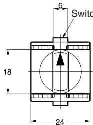
■ Operation Angle
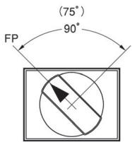
Two notches
Three notches
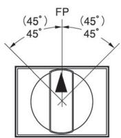
Note: 1. The angle used for automatic reset is shown in parentheses.
2. FP: Free Position
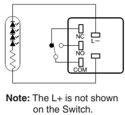
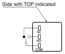
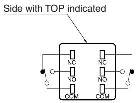
■ Contact Form
| Name | Contact |
| SPDT | COM NO |
| Notch | Contact | ||||
| SPDT | DPDT | ||||
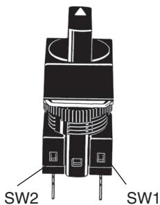
| Position | SW | Position | SW2 | SW1 | |
| 2 notches | |||||
| 3 notches | --- | ||||
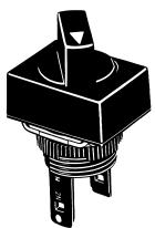
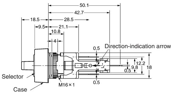
Nomenclature
Selector
Flange Shape
Rectangular (A165□-J)
Square (A165□-A)

Round (A165□-T)

Protective Structure
Oil-resistant IP65
Color of Selector
- LED models
Red, green, yellow
Non-lighted models
Black
Lighting Method
- Lighted (LED) models
(The upper face of the knob is illuminated.)
Non-lighted models
Number of Notches and Reset Method
2 Notches
Manual reset
Automatic reset
3 Notches
Manual reset
Automatic reset
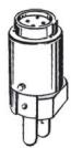
Lamp
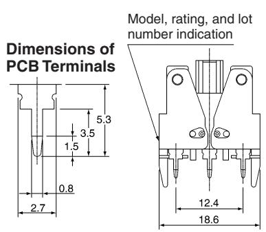
Terminal Type
- Solder terminals
TAB TERMINALS #110
PCB terminals
Switch
Switch Specifications
- Standard Loads
5 A at 125 VAC
5 A at 250 VAC
3 A at 30 VDC
Minimum applicable load: 1 mA at 5 VDC
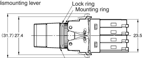
Note: All units are in millimeters unless otherwise indicated.
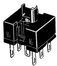
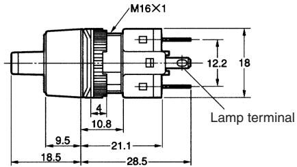
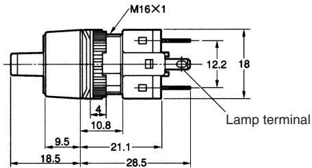
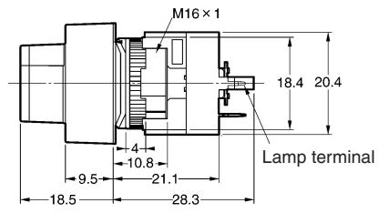
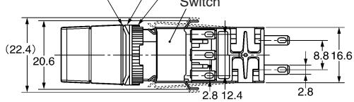
■ Knob-type Selector Switches without Voltage Reduction Unit
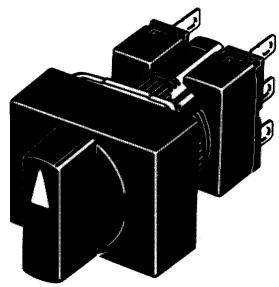
Rectangular
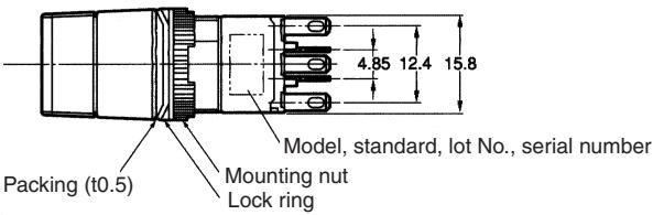
A165□-J
Solder terminals (tab terminals #110)
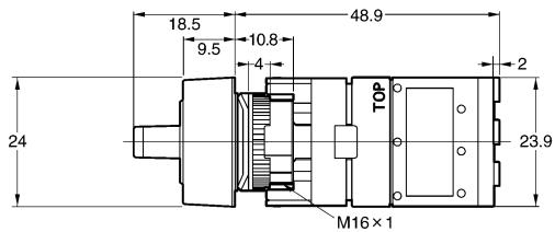
Note: See page 14 for panel cutouts.
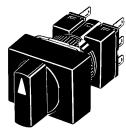
Square
A165□-A
Solder terminals (tab terminals #110)
Note: See page 14 for panel cutouts.
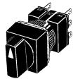
Round
A165□-T
Solder terminals (tab terminals #110)
Note: See page 14 for panel cutouts.
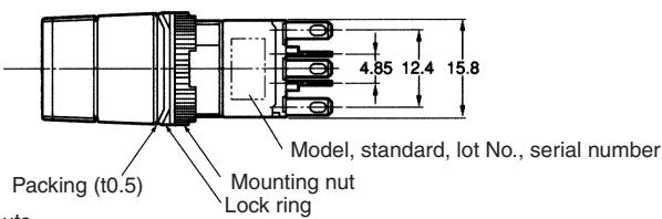
The following diagrams show the rectangular model as a representative example. The lamp terminal is also provided with non-lighted models.
Rectangular
A165J-J
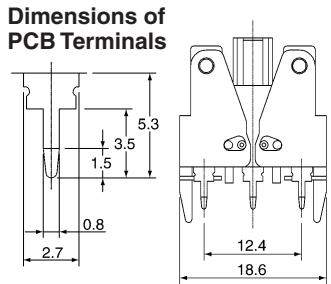
PCB terminals
Note: See page 14 for panel cutouts.
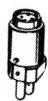
Rectangular
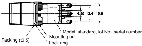
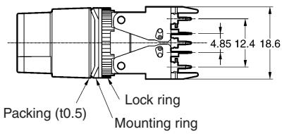
A165W□-T
Reduced-voltage light ing, solder terminals (tab terminals #110)
Packing (t0.5)
(for oil-resistant IP65 only) / Mounting ring
Rectangular
A165□-2S
Screw-Less Clamp
ch dismounting lever
Packing (t0.5)
(for oil-resistant IP65 only)
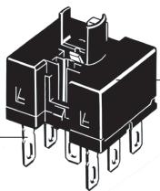
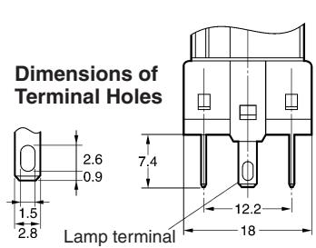
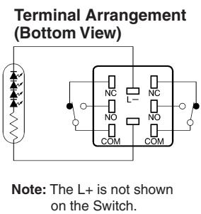
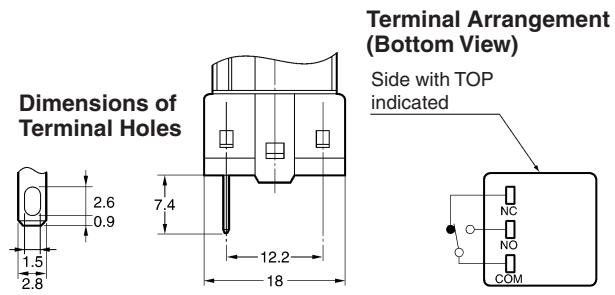
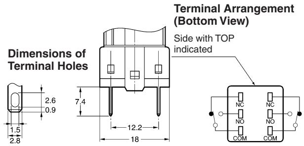
■ Terminal Arrangement
Models with Solder Terminals without Reduced-voltage Lighting
Lamp terminals are not provided with the Non-lighted Knob-type Selector Switches and Key-type Selector Switches.
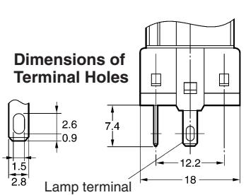
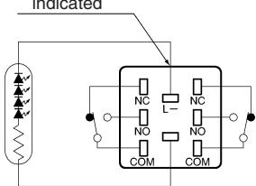
Lighted SPDT Switches
Terminal Arrangement (Bottom View)
Lighted DPDT Switches
Non-lighted SPDT Switches
Non-lighted DPDT Switches
Models with PCB Terminals
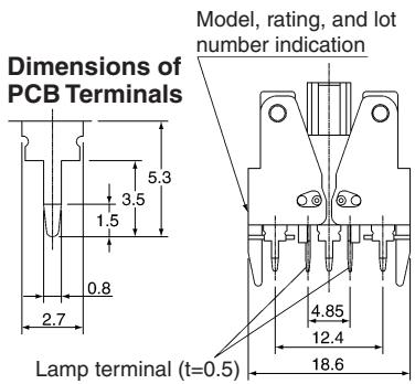
Lighted SPDT Switches
Terminal Arrangement (Bottom View)
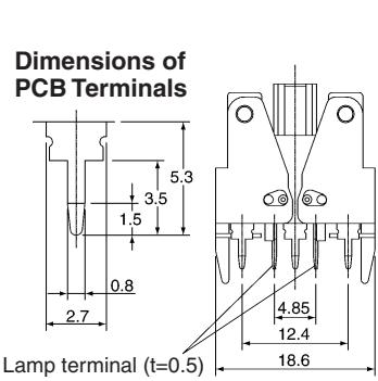
Lighted DPDT Switches
Terminal Arrangement (Bottom View) Side with TOP indicated
Note: For details of the terminal arrangement for Screw-Less Clamps, refer to the corresponding section for the A16.
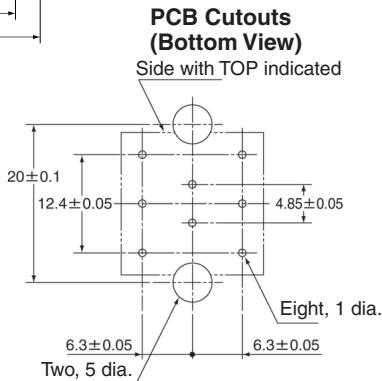
Non-lighted Models with PCB Terminals
Lamp terminals are not provided with the Non-lighted Knob-type Selector Switches and Key-type Selector Switches.
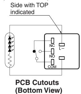
Non-lighted SPDT Switches
Terminal Arrangement (Bottom View)
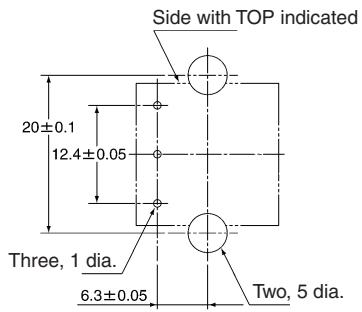
PCB Cutouts (Bottom View)
Non-lighted DPDT Switches
PCB Cutouts (Bottom View)
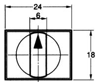
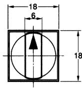
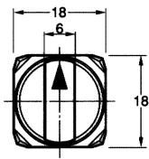
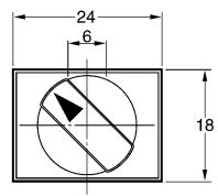
Panel Cutouts
Models with Solder Terminals
Rectangular A165□-J
(Top View)
Square A165□-A Round A165□-T
(Top View)
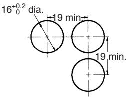
Note: 1. Make sure the thickness of the mounting panel is 0.5 to 3.2mm
2. If the panel is to be finished with coating, etc., make sure that the panel meets the specified dimensions after coating.
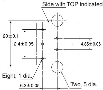
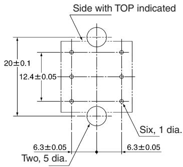
Models with PCB Terminals
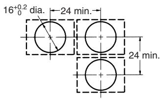
Rectangular A165□-J
(Top View)

Square A165□-A Round A165□-T
(Top View)
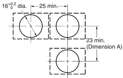
Rectangular A165W□-T
Recommended panel thickness: 0.5 to 3.2mm
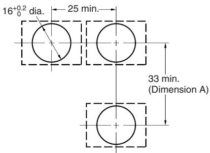
Rectangular A165-2S
Recommended panel thickness: 0.5 to 3.2mm
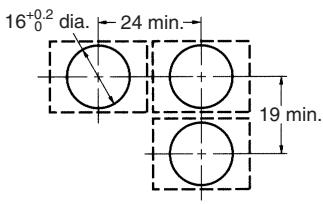
Note: 1. Ensure that the variation in the distance between the centers of neighboring mounting holes is less than ± 0.1 mm .
2. Make sure the thickness of the mounting panel is 0.5 to 3.2mm . If, however, a Switch Guard or Dust Cover is used, the thickness of the mounting panel must be 0.5 to 2mm .
3. If the panel is to be finished with coating, etc., make sure that the panel meets the specified dimensions after coating.
Installation
For details on mounting the Switch to a panel, and mounting and dismounting the Switch, refer to installation details for the A16 Pushbutton Switch.
Panel Mounting
Refer to the Installation section for the A16.
Mounting and Replacing the Pushbutton
Refer to the Installation section for the A16.
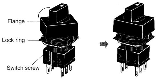
Flange Rotation
A165 Knob-type Selector Switch
Fix the Switch screw and rotate the flange in 45^ turns.
Precautions
Refer to the Technical Information for Pushbutton Switches (Cat. No. A143) and the Precautions section for the A16.
ALL DIMENSIONS SHOWN ARE IN MILLIMETERS.
To convert millimeters into inches, multiply by 0.03937. To convert grams into ounces, multiply by 0.03527.
Cat. No. A125-E1-02
In the interest of product improvement, specifications are subject to change without notice.