
61F-GPN-BT - Liquid level controller OMRON - Free user manual and instructions
Find the device manual for free 61F-GPN-BT OMRON in PDF.
| Product type | Conductive liquid level controller |
| Brand | OMRON |
| Model | 61F-GPN-BT |
| Supply voltage | 24 VDC |
| Admissible voltage range | 85% to 110% of rated voltage |
| Voltage between electrodes | 5 VAC max. |
| Operating resistance | Variable (0 to 100 kΩ) |
| Release resistance | 200% max. of operating resistance |
| Output type | Open collector (NPN) |
| Output specifications | 30 VDC, 100 mA max. |
| Supply/drain switching | Terminals 7 and 8 open: drainage; short-circuited: supply |
| Max. wiring distance | 100 m (with 0.75 mm² cable) |
| Operating ambient temperature | -10 to 55 °C |
| Operating ambient humidity | 25% to 85% |
| Insulation resistance | 100 MΩ min. (500 VDC) |
| Dielectric strength | 2,000 VAC, 50/60 Hz for 1 min |
| Power consumption | 2 W max. |
| Response time | Operation: 1.5 s max.; Release: 3.0 s max. |
| Compatible front socket | PF113A-E |
| Weight | Approx. 150 g (estimate) |
| Dimensions | Approx. 48 x 80 x 80 mm (estimate) |
| Maintenance and cleaning | Clean with a dry cloth; avoid moisture and corrosive gases |
| Safety | Do not use in flammable atmosphere; respect rated voltage |
| Spare parts and repairability | Socket PF113A-E; separate electrode holders; no user-serviceable parts |
Frequently Asked Questions - 61F-GPN-BT OMRON
User questions about 61F-GPN-BT OMRON
0 question about this device. Answer the ones you know or ask your own.
Ask a new question about this device
Download the instructions for your Liquid level controller in PDF format for free! Find your manual 61F-GPN-BT - OMRON and take your electronic device back in hand. On this page are published all the documents necessary for the use of your device. 61F-GPN-BT by OMRON.
USER MANUAL 61F-GPN-BT OMRON
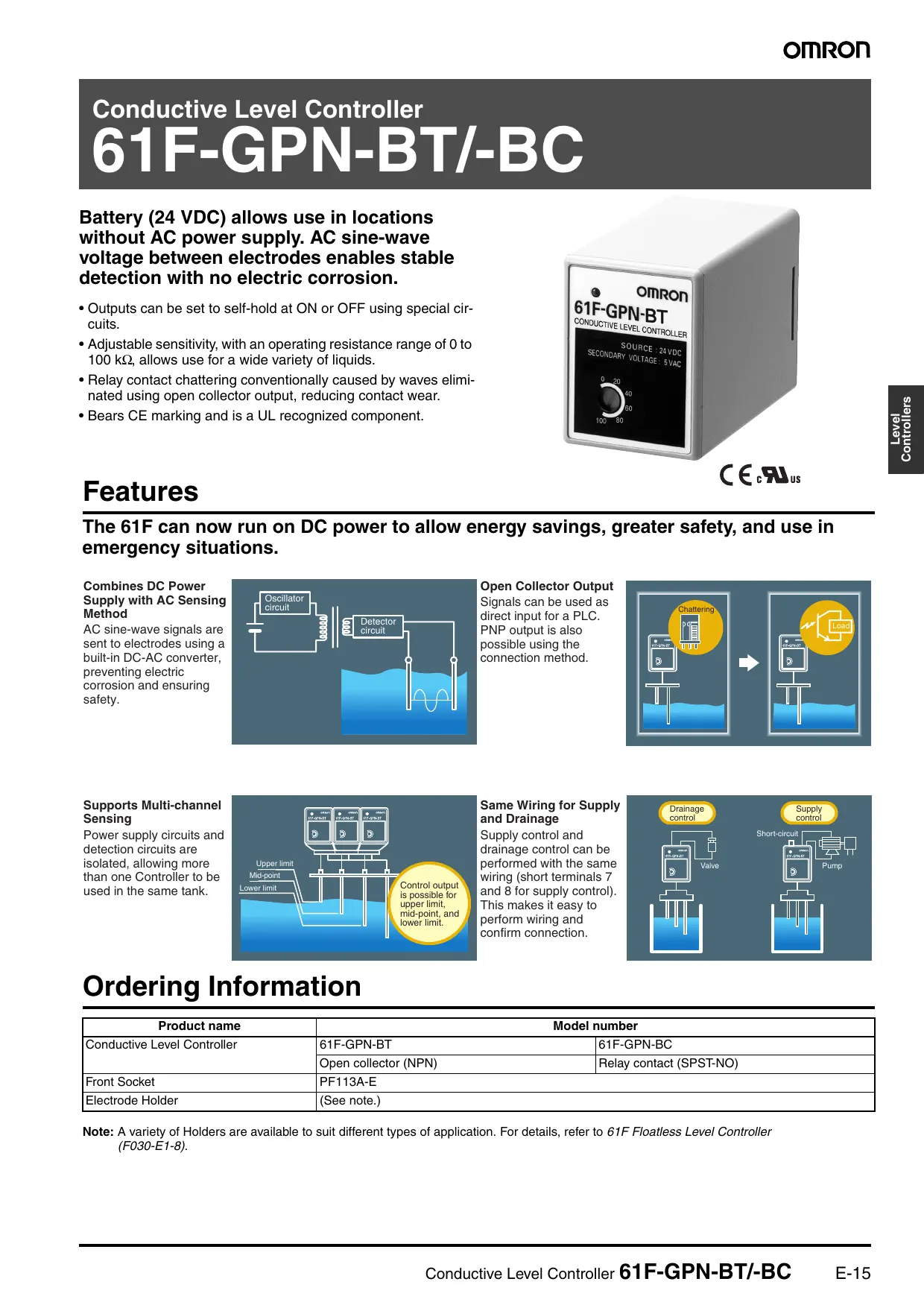
Conductive Level Controller
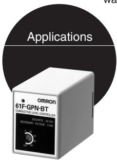
61F-GPN-BT/-BC
Battery (24 VDC) allows use in locations without AC power supply. AC sine-wave voltage between electrodes enables stable detection with no electric corrosion.
- Outputs can be set to self-hold at ON or OFF using special circuits.
- Adjustable sensitivity, with an operating resistance range of 0 to 100k , allows use for a wide variety of liquids.
- Relay contact chattering conventionally caused by waves eliminated using open collector output, reducing contact wear.
- Bears CE marking and is a UL recognized component.
C∈cRus
Features
The 61F can now run on DC power to allow energy savings, greater safety, and use in emergency situations.
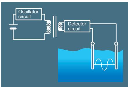
Combines DC Power Supply with AC Sensing Method
AC sine-wave signals are sent to electrodes using a built-in DC-AC converter, preventing electric corrosion and ensuring safety.
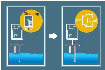
Open Collector Output Signals can be used as direct input for a PLC. PNP output is also possible using the connection method.
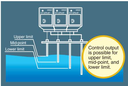
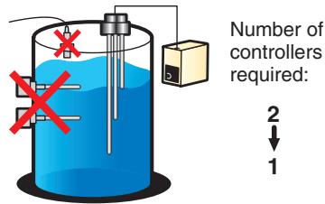
Supports Multi-channel Sensing
Power supply circuits and detection circuits are isolated, allowing more than one Controller to be used in the same tank.
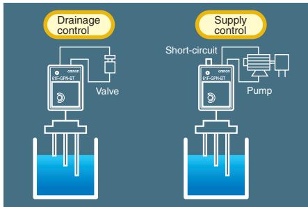
Same Wiring for Supply and Drainage
Supply control and drainage control can be performed with the same wiring (short terminals 7 and 8 for supply control). This makes it easy to perform wiring and confirm connection.
Ordering Information
| Product name | Model number | |
| Conductive Level Controller | 61F-GPN-BT | 61F-GPN-BC |
| Open collector (NPN) | Relay contact (SPST-NO) | |
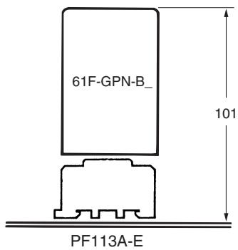
| Front Socket | PF113A-E | |
| Electrode Holder | (See note.) | |
Note: A variety of Holders are available to suit different types of application. For details, refer to 61F Floatless Level Controller (F030-E1-8).
Ratings
| 61F-GPN-BT | 61F-GPN-BC | |
| Rated voltage | 24 VDC | |
| Allowable voltage range | 85% to 110% of the rated voltage | |
| Interelectrode voltage | 5 VAC max. | |
| Operation resistance (See note 1.) | Variable (0 to 100 kΩ) | |
| Error | For scale of 0: +10 kΩ; For scale of 100: ±10 kΩ | |
| Release resistance | 200% max. of the operation resistance | |
| Switching between supply and drainage | Terminals 7 and 8 open: Automatic drainage operation Terminals 7 and 8 shorted: Automatic supply operation | |
| Output specifications | Open collector (NPN) 30 VDC, 100 mA max. | SPST-NO 5 A, 240 VAC (Resistive load) 2 A, 240 VAC (Inductive load: cosφ=0.4) |
| Life expectancy | --- | Electrical: 100,000 operations min. Mechanical: 20,000,000 operations min. |
| Wiring distance (See note 2.) | 100 m max. | |
Note: 1. The 61F may not operate at resistance settings close to zero. Adjust the sensitivity to match actual usage conditions.
2. The figure for wiring distance above is for when 600-V 3-core cabtyre cable with a cross-sectional area of 0.75mm^2 is used.
Characteristics
| Ambient operating temperature | -10 to 55°C |
| Ambient operating humidity | 25% to 85% |
| Insulation resistance | 100 MΩ min. (at 500 VDC) |
| Dielectric strength (See note.) | 2,000 VAC, 50/60 Hz for 1 minute |
| Power consumption | 2 W max. |
| Response time | Operating: 1.5 s max. Releasing: 3.0 s max. |
Note: The dielectric strength is measured between power terminals and electrode terminals, power terminals and output terminals, and between electrode terminals and output terminals.
Connections
Automatic Drainage Operation
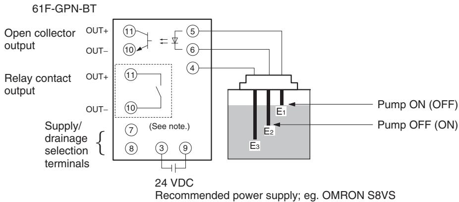
Note: The part within the dotted-line box is for the 61F-GPN-BC (relay-output type) only.
Automatic Water Supply Operation
Short terminals 7 and 8 for automatic water supply operation. (Operation shown in parentheses in the diagram above.)
■ Reading Signals for the Liquid Level Only (No Control)
Only E1 and E3 are used. Output will turn ON when the liquid level reaches E1 if terminals 7 and 8 are open, and will turn OFF if terminals 7 and 8 are closed. Also, to take signals for liquid level at several points, use terminal 4 as a common for all of the Controllers and use terminal 5 of each Controller as an electrode.
Note: If terminals 7 and 8 are shorted, operation of the 61F relay is "de-energizing" (i.e., energized normally and de-energized when liquid is present across the electrodes). Therefore, if the power supply connected across terminals 3 and 9 is interrupted, the output from terminals 10 and 11 will turn OFF, enabling detection of power interruptions.
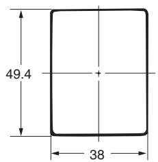
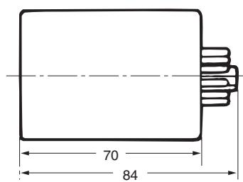
Dimensions
Application Examples
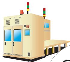
Drainage control for semiconductor wafer cleaning installations.
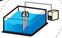
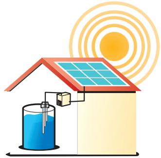
Liquid level control for solar power generation systems.
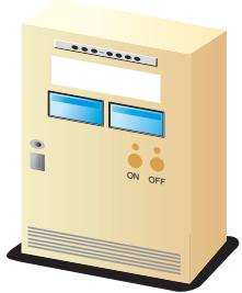
Meet safety standards by using DC power supply for all devices in a panel.
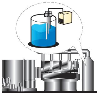
Liquid level control for waste-heat recovery boilers in co-generation systems.
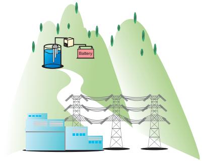
Liquid level control for remote regions without AC power supply.
Cut costs by using the 61F in situations where ultrasonic/electrostatic capacity level controllers were used because only DC power supply was available.
General Precautions
Before using the Controller under conditions not described in the relevant documents or applying the Controller to nuclear control systems, railroad systems, aviation systems, vehicles, combustion systems, medical equipment, amusement machines, safety equipment and other systems, machines, and equipment that may have a serious influence on lives and property if used improperly, consult your OMRON representative.
Make sure that the ratings and performance characteristics of the Controller are sufficient for the systems, machines, and equipment and be sure to provide the systems, machines, and equipment with double safety-mechanisms.
Safety Precautions
In order to ensure safe operation, be sure to observe the following points.
- Use a power supply voltage within the specified range.
- Do not use the Controller in locations subject to flammable gases or objects.
- Insert the Socket until it securely clicks into place.
- Do not short the load connected to the output terminals.
- Do not connect the power supply in reverse.
Correct Use
Mounting
Mount to a panel of thickness 1 to 5mm
Do not mount the Controller in the following places.
- Locations subject to strong vibrations or shocks.
- Locations outside the specified temperature and humidity ranges, or locations prone to condensation. (The Controller detects high impedances. Do not use in locations subject to high humidity levels.)
- Locations subject to dust.
- Locations subject to corrosive gases (in particular, sulphurized gas or ammonia gas).
- Outdoors, or in locations subject to direct sunlight.
- Near devices that generate strong, high-frequency noise (e.g., high-frequency welders, machines).
ALL DIMENSIONS SHOWN ARE IN MILLIMETERS.
To convert millimeters into inches, multiply by 0.03937. To convert grams into ounces, multiply by 0.03527.
Cat. No. F053-E1-02
In the interest of product improvement, specifications are subject to change without notice.