
IB9 - Motherboard ABIT - Free user manual and instructions
Find the device manual for free IB9 ABIT in PDF.

| Product Type | Motherboard |
| Brand | ABIT |
| Model | IB9 |
| Form Factor | ATX (305 x 244 mm) |
| Processor Socket | LGA775 |
| Chipset | Intel P965 + ICH8 |
| Memory Type | DDR2 SDRAM |
| Number of Memory Slots | 4 (2 channels) |
| Maximum Memory Capacity | 8 GB |
| SATA Connectors | 4 (SATA 3 Gbit/s) |
| IDE Connectors | 2 (1 channel) |
| Floppy Connector | 1 |
| Front USB Ports (Internal) | 4 (2 connectors) |
| Front IEEE1394 Ports (Internal) | 2 (2 connectors) |
| Audio | HD Audio 7.1 channels, Optical SPDIF input/output |
| Network | Gigabit Ethernet |
| Power Connectors | ATX 24-pin, ATX12V 4-pin |
| Fan Connectors | CPU, system, auxiliary, Northbridge |
| Rear Ports | PS/2 mouse and keyboard, LPT, COM, 4 USB, 2 IEEE1394, Optical SPDIF, 7.1 audio, LAN |
| Special Features | CMOS clear jumper, HD Audio and AC'97 support |
| Included Software | Drivers and utilities (downloadable) |
| Operating Temperature | 0°C to 50°C (estimated) |
| Weight | Approximately 800 g |
Frequently Asked Questions - IB9 ABIT
User questions about IB9 ABIT
0 question about this device. Answer the ones you know or ask your own.
Ask a new question about this device
Download the instructions for your Motherboard in PDF format for free! Find your manual IB9 - ABIT and take your electronic device back in hand. On this page are published all the documents necessary for the use of your device. IB9 by ABIT.
USER MANUAL IB9 ABIT
Pentium Extreme Edition,
Pentium D, Pentium 4
Intel P965/ICH8
FSB1066
Dual DDR2 800
PCI Express
Gigabit LAN
4x SATA 3Gb/s
7.1 Channel HD Audio
IB9
User's Manual
English + Multilingual QIG
1^st Edition, October 2006
Copyright and Warranty Notice
The information in this document is subject to change without notice and does not represent a commitment on part of the vendor, who assumes no liability or responsibility for any errors that may appear in this manual.
No warranty or representation, either expressed or implied, is made with respect to the quality, accuracy or fitness for any particular part of this document. In no event shall the manufacturer be liable for direct, indirect, special, incidental or consequential damages arising from any defect or error in this manual or product.
Product names appearing in this manual are for identification purpose only and trademarks and product names or brand names appearing in this document are the property of their respective owners.
This document contains materials protected under International Copyright Laws. All rights reserved. No part of this manual may be reproduced, transmitted or transcribed without the expressed written permission of the manufacturer and authors of this manual.
If you do not properly set the motherboard settings, causing the motherboard to malfunction or fail, we cannot guarantee any responsibility.
1. Hardware Setup 1-1
1.1 Specifications 1-1
1.2 Motherboard Layout 1-2
1.3 Choosing a Computer Chassis 1-3
1.4 Installing Motherboard 1-3
1.5 Checking Jumper Settings 1-4
1.5.1 CMOS Memory Clearing Header and Backup Battery 1-4
1.5.2 Wake-up Header 1-6
1.6 Connecting Chassis Components 1-7
1.6.1 ATX Power Connectors 1-7
1.6.2 Front Panel Switches & Indicators Headers 1-8
1.6.3 FAN Power Connectors 1-9
1.7 Installing Hardware 1-10
1.7.1 CPU Socket 775 1-10
1.7.2 DDR2 Memory Slots 1-12
1.8 Connecting Peripheral Devices 1-13
1.8.1 Floppy and IDE Disk Drive Connectors 1-13
1.8.2 Serial ATA Connectors 1-14
1.8.3 Additional USB 2.0 Port Headers.. 1-15
1.8.4 Internal Audio Connectors 1-16
1.8.5 Front Panel Audio Connection Header 1-16
1.8.6 PCI and PCI Express X16, X1 Slots 1-18
1.9 Onboard Status Display 1-19
1.9.1 Power Source Indicators 1-19
1.10 Connecting Rear Panel I/O Devices 1-20
2. BIOS Setup 2-1
2.1 SoftMenu Setup 2-2
2.2 Standard CMOS Features 2-4
2.3 Advanced BIOS Features 2-7
2.4 Advanced Chipset Features 2-10
2.5 Integrated Peripherals 2-12
2.6 Power Management Setup 2-15
2.7 PnP/PCI Configurations 2-17
2.8 PC Health Status 2-18
2.9 Load Fail-Safe Defaults 2-20
2.10 Load Optimized Defaults.. 2-20
2.11 Set Password 2-20
2.12 Save & Exit Setup 2-20
2.13 Exit Without Saving 2-20
3. Driver & Utility 3-1
3.1 Intel Chipset Software Installation Utility 3-2
3.2 Audio Driver 3-2
3.3 LAN Driver 3-2
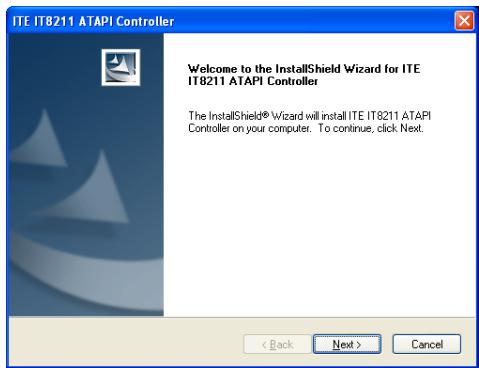
3.4 iTE IDE Controller Driver 3-3
3.5 USB 2.0 Driver 3-3
3.6 ABIT EQ (The Hardware Doctor Utility) 3-4
3.7 FlashMenu (BIOS Update Utility) 3-5
3.8 Build A Driver Disk Under Windows Environment 3-6
3.9 Build A Driver Disk Under DOS Environment 3-7
4. Multilingual Quick Installation Guide 4-1
4.1 French//Guide d'Installation Rapide 4-1
4.2 German//Kurze Installationsanleitung 4-3
4.3 Italian//Guida all'installazione rapida 4-5
4.4 Spanish//Guía rápida de instalación 4-7
4.5 Portuguese//Guia de instalação rápida 4-9
4.6 Russian//KpaTkoe pyKOBOCTBO no yCTaHOBKe 4-11
4.7 Estonian//Kiirpaigaldusjuhend 4-13
4.8 Latvian//Atras installesanas instrukcija 4-15
4.9 Lithuanian//Trumpas instaliavimo vadovas 4-17
4.10 Polish//Instrukcja szybkiej instalacji 4-19
4.11 Hungarian//Gyorstelepiétiú utmutató 4-21
4.12 Turkish//Hizli Kurulum Kilavuzu 4-23
4.13 Arabic// 4-25
4.14 Persian///
4.15 Japanese//クイックインストーリド 4-29
4.16 Korean//哪部电影 哪部电影 4-31
4.17 Malay//Panduan Pemasangan Ringkas 4-33
4.18 Thai//nannnnnnnnnnnnnnnnnnnnnnnnnnnnnnnnnnnnnnnnnnnnnnnnnnnnnnnnnnnnnnnnnnnnnnnnnnnnnnnnnnnnnnnnnnnnnnnnnnnnnnnnnnnnnnnnnnnnnnnn
4.19 繁體中交 4-37
5.1 Troubleshooting (How to Get Technical Support?) 5-1
5.1.1 Q & A. 5-1
5.1.2 Technical Support Form 5-4
5.1.3 Contact Information 5-5
1. Hardware Setup
1.1 Specifications
CPU
Support Intel Core 2 Duo, Pentium Extreme Edition, Pentium D, Pentium 4 Processor with 1066/800MHz FSB
Chipset
Intel P965/ICH8
Memory
- 4x 240-pin DIMM slots support maximum memory capacity up to 8GB
Supports Dual Channel DDR2 800/667/533 Un-buffered Non-ECC memory
LAN
- Onboard 10/100/1000M PCI controller
Audio
- Onboard 7.1 CH HD Audio CODEC
Serial ATA
4x SATA 3Gb/s
Expansion Slots
- 1x PCI-E X16 slot
- 3x PCI-E X1 slots
- 2x PCI slots
Internal I/O Connectors
1x Floppy port
2x ATA 100 IDE connectors
4x SATA 3Gb/s connectors
- 3x USB 2.0 headers
1x FP-Audio header
1x CD-In connector
Rear Panel I/O
1x PS/2 Keyboard connector
- 1x PS/2 Mouse connector
1x S/PDIF Out
1x 7.1CH Audio Connector
4x USB 2.0 connectors
- 1x RJ-45 Gigabit LAN connector
ABIT Engineered
- ABIT SoftMenu™ Technology
RoHS
100% Lead-free process and RoHS compliant
Miscellaneous
- ATX form factor (305mm x 245mm)
※ Specifications and information contained herein are subject to change without notice.
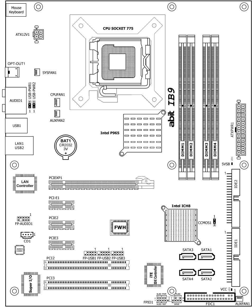
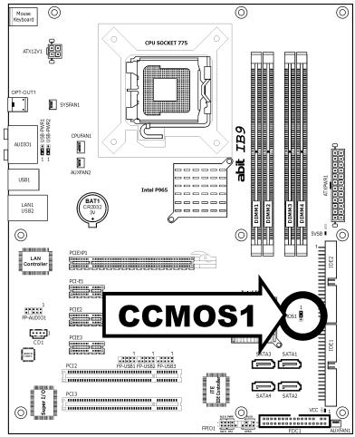
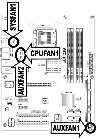
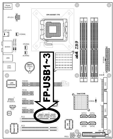
1.2 Motherboard Layout
1.3 Choosing a Computer Chassis
- Choose a chassis big enough to install this motherboard.
- As some features for this motherboard are implemented by cabling connectors on the motherboard to indicators and switches or buttons on the chassis, make sure your chassis supports all the features required.
- If there is possibility of adopting some more hard drives, make sure your chassis has sufficient power and space for them.
- Most chassis have alternatives for I/O shield located at the rear panel. Make sure the I/O shield of the chassis matches the I/O port configuration of this motherboard. You can find an I/O shield specifically designed for this motherboard in its package.
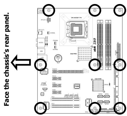
1.4 Installing Motherboard
Most computer chassis have a base with many mounting holes to allow the motherboard to be securely attached, and at the same time, prevent the system from short circuits. There are two ways to attach the motherboard to the chassis base: (1) with studs, or (2) with spacers.
Basically, the best way to attach the board is with studs. Only if you are unable to do this should you attach the board with spacers. Line
up the holes on the board with the mounting holes on the chassis. If the holes line up and there are screw holes, you can attach the board with studs. If the holes line up and there are only slots, you can only attach with spacers. Take the tip of the spacers and insert them into the slots. After doing this to all the slots, you can slide the board into position aligned with slots.
After the board has been positioned, check to make sure everything is OK before putting the chassis back on.
Always power off the computer and unplug the AC power cord before adding or removing any peripheral or component. Failing to so may cause severe damage to your motherboard and/or peripherals. Plug in the AC power cord only after you have carefully checked everything.
To install this motherboard:
- Locate all the screw holes on the motherboard and the chassis base.
- Place all the studs or spacers needed on the chassis base and have them tightened.
- Face the motherboard's I/O ports toward the chassis's rear panel.
- Line up all the motherboard's screw holes with those studs or spacers on the chassis.
- Install the motherboard with screws and have them tightened.
※ To prevent shorting the PCB circuit, please REMOVE the metal studs or spacers if they are already fastened on the chassis base and are without mounting-holes on the motherboard to align with.
1.5 Checking Jumper Settings
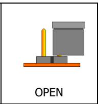
- For a 2-pin jumper, plug the jumper cap on both pins will make it CLOSE (SHORT). Remove the jumper cap, or plug it on either pin (reserved for future use) will leave it at OPEN position.
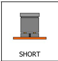
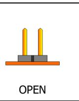
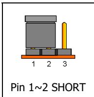
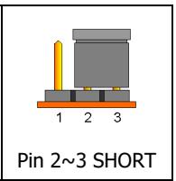
For 3-pin jumper, pin 1 2 or pin 2 3 can be shorted by plugging the jumper cap in.
1.5.1 CMOS Memory Clearing Header and Backup Battery
The time to clear the CMOS memory occurs when (a) the CMOS data becomes corrupted, (b) you forgot the supervisor or user password preset in the BIOS menu, (c) you are unable to boot-up the system because the CPU ratio/clock was incorrectly set in the BIOS menu, or (d) whenever there is modification on the CPU or memory modules.
This header uses a jumper cap to clear the CMOS memory and have it reconfigured to the default values stored in BIOS.
- Pins 1 and 2 shorted (Default): Normal operation.
- Pins 2 and 3 shorted: Clear CMOS memory.
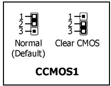
To clear the CMOS memory and load in the default values:
- Power off the system.
- Set pin 2 and pin 3 shorted by the jumper cap. Wait for a few seconds. Set the jumper cap back to its default settings --- pin 1 and pin 2 shorted.
- Power on the system.
- For incorrect CPU ratio/clock settings in the BIOS, press
key to enter the BIOS setup menu right after powering on system. - Set the CPU operating speed back to its default or an appropriate value.
- Save and exit the BIOS setup menu.
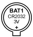
CMOS Backup Battery:
An onboard battery saves the CMOS memory to keep the BIOS information stays on even after disconnected your system with power source. Nevertheless, this backup battery exhausts after some five years. Once the error message like "CMOS BATTERY HAS Failed" or "CMOS checksum error" displays on monitor, this backup battery is no longer functional and has to be renewed.
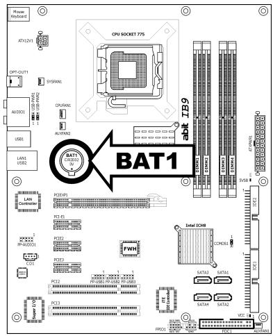
To renew the backup battery:
- Power off the system and disconnect with AC power source.
- Remove the exhausted battery.
- Insert a new CR2032 or equivalent battery. Pay attention to its polarity. The "+" side is its positive polarity.
- Connect AC power source and power on the system.
- Enter the BIOS setup menu. Reconfigure the setup parameters if necessary.
CAUTION:
Danger of explosion may arise if the battery is incorrectly renewed.
Renew only with the same or equivalent type recommended by the battery manufacturer.
※ Dispose of used batteries according to the battery manufacturer's instructions.
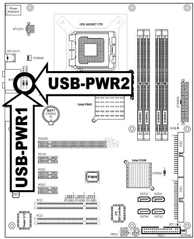
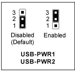
1.5.2 Wake-up Header
These headers use a jumper cap to enable/disable the wake-up function.
USB-PWR1:
Pin 1-2 shorted (Default): Disable wake-up function support at USB1 port.
Pin 2-3 shorted: Enable wake-up function support at USB1 port.
USB-PWR2:
Pin 1-2 shorted (Default): Disable wake-up function support at USB2 port.
Pin 2-3 shorted: Enable wake-up function support at USB2 port
1.6 Connecting Chassis Components
1.6.1 ATX Power Connectors
These connectors provide the connection from an ATX power supply. As the plugs from the power supply fit in only one orientation, find the correct one and push firmly down into these connectors.
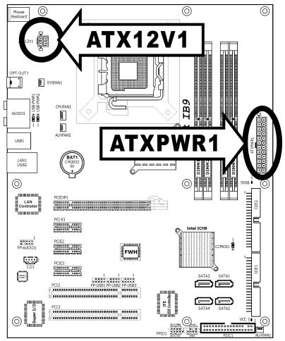
ATX 24-Pin Power Connector:
The power supply with 20-pin or 24-pin cables can both be connected to this 24-pin connector. Connect from pin-1 for either type. However, a 20-pin power supply may cause the system unstable or even unbootable for the sake of insufficient electricity. A minimum power of 300W or higher is recommended.
ATX 12V 4-Pin Power Connector:
This connector supplies power to CPU. The system will not start without connecting power to this one.
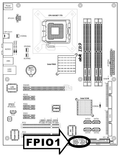
1.6.2 Front Panel Switches & Indicators Headers
This header is used for connecting switches and LED indicators on the chassis front panel.
Watch the power LED pin position and orientation. The mark "+" align to the pin in the figure below stands for positive polarity for the LED connection. Please pay attention when connecting these headers. A wrong orientation will only cause the LED not lighting, but a wrong connection of the switches could cause system malfunction.
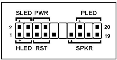
HLED (Pin 1, 3):
Connects to the HDD LED cable of chassis front panel.
RST (Pin 5, 7):
Connects to the Reset Switch cable of chassis front panel.
- SPKR (Pin 13, 15, 17, 19):
Connects to the System Speaker cable of chassis.
SLED (Pin 2, 4):
Connects to the Suspend LED cable (if there is one) of chassis front panel.
PWR (Pin 6, 8):
Connects to the Power Switch cable of chassis front panel.
PLED (Pin 16, 18, 20):
Connects to the Power LED cable of chassis front panel.
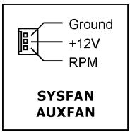
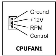
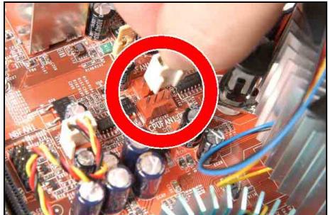
1.6.3 FAN Power Connectors
These connectors each provide power to the cooling fans installed in your system.
- CPUFAN1: CPU Fan Power Connector
- SYSFAN1: System Fan Power Connector
AUXFAN1~2: Auxiliary Fan Power Connector
These fan connectors are not jumpers. DO NOT place jumper caps on these connectors.
1.7 Installing Hardware
※ DO NOT scratch the motherboard when installing hardware. An accidentally scratch of a tiny surface-mount component may seriously damage the motherboard.
※ In order to protect the contact pins, please pay attention to these notices:
- A maximum 20 cycles of CPU installation is recommended.
- Never touch the contact pins with fingers or any object.
- Always put on the cap when the CPU is not in use.
1.7.1 CPU Socket 775
The installation procedures vary with different types of CPU fan-and-heatsink assembly. The one shown here is served for demo only. For detailed information on how to install the one you bought, refer to its installation guidelines.
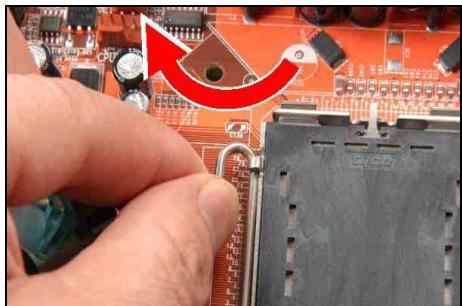
1. Place the board so as to let the lever-hook of the socket is on your left side. Use your left thumb and forefinger to hold the lever hook, pull it away from the retention tab. Rotate the lever to fully open position.
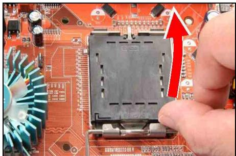
2. Use your right-thumb to raise the load plate. Lift it up to fully open position.
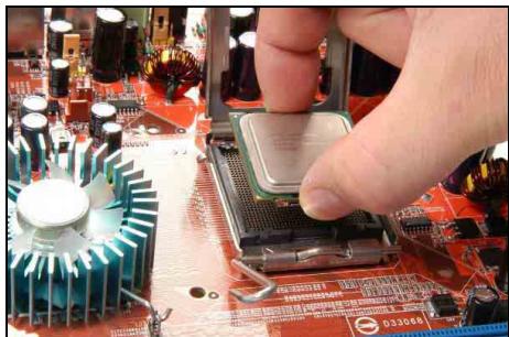
3. Use your right thumb and forefinger to grasp the CPU package. Be sure to grasp on the edge of the substrate, and face the Pin-1 indicator toward the bottom-left side. Aim at the socket and place the CPU package vertical down into the socket.
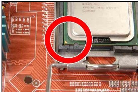
4. Visually inspect if the CPU is seated well into the socket. The alignment key must be located in the notch of package.
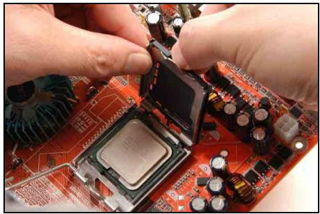
- Use your left hand to hold the load plate, and use your right thumb to peel the cap off.
The cap plays an important role in protecting contact pins. In order to prevent bent pin, PUT ON the cap after operation or testing.
- Lower the plate onto the CPU package. Engage the load lever while gently pressing down the load plate.
- Secure the lever with the hook under retention tab.
- Place the heatsink and fan assembly onto the socket. Align the four fasteners toward the four mounting holes on the motherboard.
- Press each of the four fasteners down into the mounting holes. Rotate the fastener clock-wise to lock the heatsink and fan assembly into position.
- Attach the four-pin power plug from the heatsink and fan assembly to the CPU FAN connector.
A higher fan speed will be helpful for better airflow and heat-dissipation. Nevertheless, stay alert to touch any heatsink since the high temperature generated by the working system is still possible.
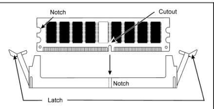
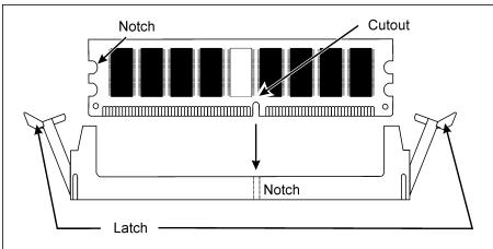
1.7.2 DDR2 Memory Slots
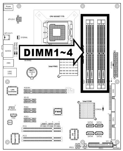
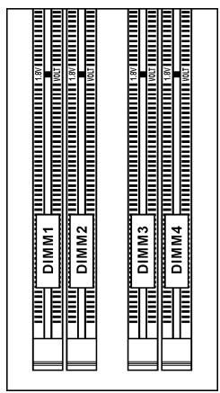
- To reach the optimum performance in dual-channel configurations, install identical DDR2 DIMM pairs for each channel.
- Install DIMMs with the same CAS latency. To reach the optimum compatibility, obtain memory modules from the same vendor.
Usually there is no hardware or BIOS setup required after adding or removing memory modules, but you will have to clear the CMOS memory first if any memory module related problem occurs.
To install system memory:
- Power off the computer and unplug the AC power cord before installing or removing memory modules.
- Locate the DIMM slot on the board.
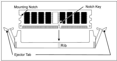
- Hold two edges of the DIMM module carefully, keep away from touching its connectors.
- Align the notch key on the module with the rib on the slot.
- Firmly press the module into the slots until the ejector tabs at both sides of the slot automatically snap into the mounting notch. Do not force the DIMM module in with extra force as the DIMM module only fits in one direction.
- To remove the DIMM modules, push the two ejector tabs on the slot outward simultaneously, and then pull out the DIMM module.
Static electricity can damage the electronic components of the computer or optional boards. Before starting these procedures, ensure that you are discharged of static electricity by touching a grounded metal object briefly.
1.8 Connecting Peripheral Devices
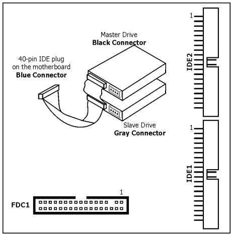
1.8.1 Floppy and IDE Disk Drive Connectors
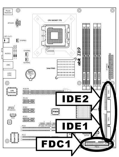
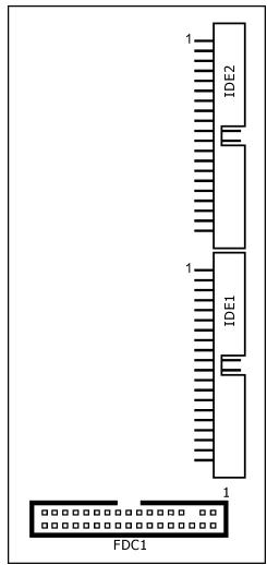
The FDC1 connector connects up to two floppy drives with a 34-wire, 2-connector floppy cable. Connect the single end at the longer length of ribbon cable to the FDC1 on the board, the two connectors on the other end to the floppy disk drives connector. Generally you need only one floppy disk drive in your system.
The red line on the ribbon cable must be aligned with pin-1 on both the FDC1 port and the floppy connector.
Each of the IDE port connects up to two IDE drives at Ultra ATA/100 mode by one 40-pin, 80-conductor, and 3-connector Ultra ATA/66 ribbon cables.
Connect the single end (blue connector) at the longer length of ribbon cable to the IDE port of this board, the other two ends (gray and black connector) at the shorter length of the ribbon cable to the connectors of your hard drives.
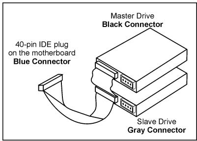
※ Make sure to configure the "Master" and "Slave" relation before connecting two drives by one single ribbon cable. The red line on the ribbon cable must be aligned with pin-1 on both the IDE port and the hard-drive connector.
※ You will have to install the "iTE IDE Controller Driver" first to enable the IDE1 and IDE2 connections.
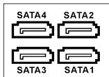
1.8.2 Serial ATA Connectors
Each SATA connector serves as one single channel to connect one SATA device by SATA cable.
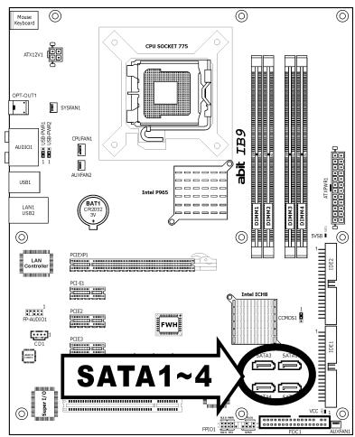
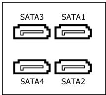
To connect SATA device:
- Attach either end of the signal cable to the SATA connector on motherboard. Attach the other end to SATA device.
- Attach the SATA power cable to the SATA device and connect the other end from the power supply.
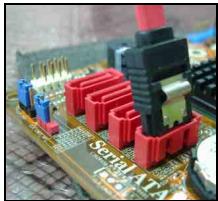
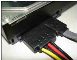
The motherboard in this illustration is served for DEMO only, may not be the same type or model as the one described in this user's manual.
1.8.3 Additional USB 2.0 Port Headers
Each header supports 2x additional USB 2.0 ports by connecting bracket or cable to the rear I/O panel or the front-mounted USB ports of your chassis.
| Pin | Pin Assignment | Pin | Pin Assignment |
| 1 | VCC | 2 | VCC |
| 3 | Data0 - | 4 | Data1 - |
| 5 | Data0 + | 6 | Data1 + |
| 7 | Ground | 8 | Ground |
| 10 | NC |
※ Make sure the connecting cable bears the same pin assignment.
1.8.4 Internal Audio Connectors
This connector connects to the audio output of internal CD-ROM drive or add-on card.
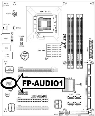
1.8.5 Front Panel Audio Connection Header
This header provides the front panel connection for HD (High Definition) Audio, yet for AC'97 Audio CODEC connection, you must carefully check the pin assignment before connecting from the front panel module. An incorrect connection may cause malfunction or even damage the motherboard.
※ Please do not connect the "Ground" cable or "USB VCC" cable from the front panel module to the Pin 4 "AVCC" of this header.
| Pin | Pin Assignment (HD AUDIO) |
| 1 | MIC2 L |
| 2 | AGND |
| 3 | MIC2 R |
| 4 | AVCC |
| 5 | FRO-R |
| 6 | MIC2_JD |
| 7 | F_IO_SEN |
| 9 | FRO-L |
| 10 | LINE2_JD |
| Pin | Pin Assignment (AC'97 AUDIO) |
| 1 | MIC In |
| 2 | GND |
| 3 | MIC Power |
| 4 | NC |
| 5 | Line Out (R) |
| 6 | NC |
| 7 | NC |
| 9 | Line Out (L) |
| 10 | NC |
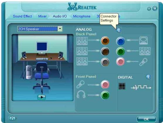
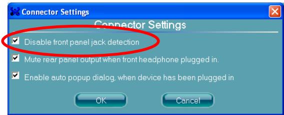
Driver Configuration for AC'97 audio connection:
The audio driver is originally configured to support HD Audio. For AC'97 audio connection, you may:
- Right-click the "Realtek HD Audio Manager" icon in system tray.
- Click "Audio I/O" tab, and then click "Connector Settings".
- Click "Disabled front panel jack detection", and then click "OK" to confirm.
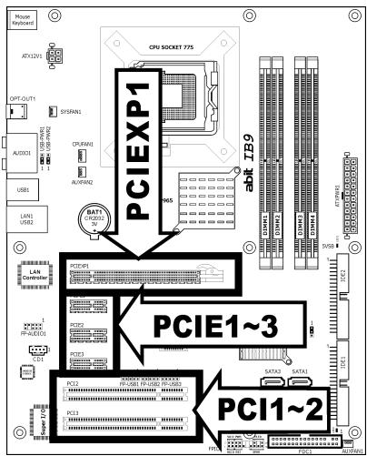
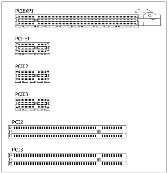
1.8.6 PCI and PCI Express X16, X1 Slots
Install PCI Express X16 graphics card into slot "PCIEXP1".
Install PCI Express X1 cards into slots "PCI-E1", "PCI-E2", and/or "PCI-E3".
Install PCI cards into slots "PCI1" and/or "PCI2".
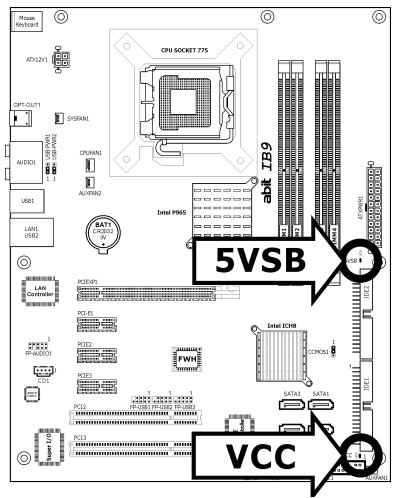
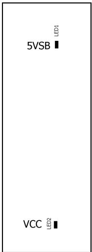
1.9 Onboard Status Display
1.9.1 Power Source Indicators
These indicators work as a reminding device to display the power status of this motherboard with power source connected.
5VSB: This LED lights up when the power supply is connected with power source.
VCC: This LED lights up when the system power is on.
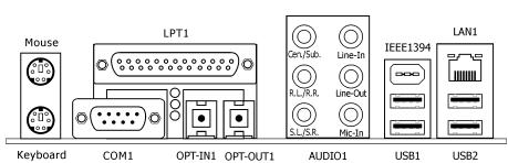
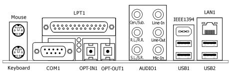
1.10 Connecting Rear Panel I/O Devices
The rear I/O part of this motherboard provides the following I/O ports:
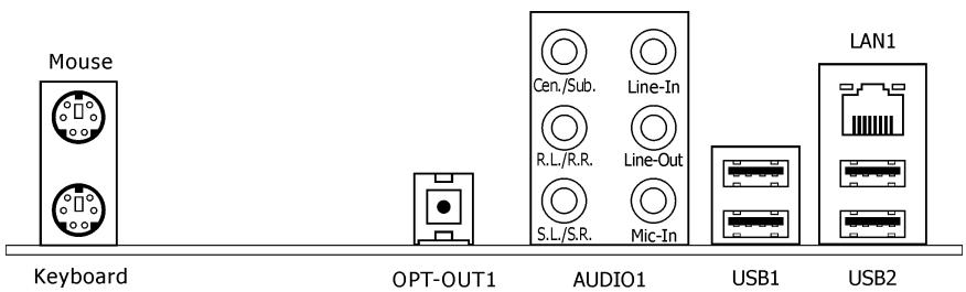
- Mouse: Connects to PS/2 mouse.
Keyboard: Connects to PS/2 keyboard. - OPT-OUT1: This connector provides an S/PDIF-Out connection through optical fiber to digital multimedia devices.
AUDIO1:
Cen./Sub. (Center / Subwoofer): Connects to the center and subwoofer channel in the 7.1 channel audio system.
R.L./R.R. (Rear Left / Rear Right): Connects to the rear left and rear right channel in the 7.1 channel audio system.
S.L./S.R. (Surround Left / Surround Right): Connects to the surround left and surround right channel in the 7.1 channel audio system.
Line-In: Connects to the line out from external audio sources.
Line-Out: Connects to the front left and front right channel in the 7.1-channel or regular 2-channel audio system.
Mic-In: Connects to the plug from external microphone.
LAN1: Connects to Local Area Network.
- USB1/USB2: Connects to USB devices such as scanner, digital speakers, monitor, mouse, keyboard, hub, digital camera, joystick etc.
2. BIOS Setup
This motherboard provides a programmable EEPROM so that you can update the BIOS utility. The BIOS (Basic Input/Output System) is a program that deals with the basic level of communication between processor and peripherals. Use the BIOS Setup program only when installing motherboard, reconfiguring system, or prompted to "Run Setup". This chapter explains the Setup Utility of BIOS utility.
After powering up the system, the BIOS message appears on the screen, the memory count begins, and then the following message appears on the screen:
PRESS DEL TO ENTER SETUP
If this message disappears before you respond, restart the system by pressing <Ctrl> + <Alt> + <Del> keys, or by pressing the Reset button on computer chassis. Only when these two methods fair should you restart the system by powering it off and then back on.
After pressing <Del> key, the main menu screen appears.
| Phoenix - AwardBIOS CMOS Setup Utility | |
| ► SoftMenu Setup► Standard CMOS Features► Advanced BIOS Features► Advanced Chipset Features► Integrated Peripherals► Power Management Setup► PnP/PCI Configurations | ► PC Health StatusLoad Fail-Safe DefaultsLoad Optimized DefaultsSet PasswordSave & Exit SetupExit Without Saving |
| Esc: Quit↑↓→← : Select ItemF10: Save & Exit Setup (i965-W627EHG-6A79LA1BC-00) | |
| Change CPU's Clock & Voltage | |

In order to increase system stability and performance, our engineering staff is constantly improving the BIOS menu. The BIOS setup screens and descriptions illustrated in this manual are for your reference only, and may not completely match with what you see on your screen.
2.1 SoftMenu Setup
This option configures the CPU's clock and voltage.
| Phoenix - AwardBIOS CMOS Setup Utility SoftMenu Setup | |
| Brand Name: Genuine Intel(R) CPU 3.60GHz Frequency: 3.60GHz Cache Size: 1024K | Item Help |
| CPU Operating Speed 3600(200) x - External Clock 200MHz x - Multiplier Factor 18 X x - Estimated New CPU Clock 3.60GHz x - N/B Strap CPU As By CPU x - DRAM Spec. (CPU:DRAM) By SPD x - PCI Express Frequency 100MHz | |
| Voltages Control Default x - CPU Core Voltage 1.3875v x - DDR2 Voltage 1.80v x - MCH Voltage 1.250v | |
| ↑↓→←:Move Enter:Select +/-/PU/PD:Value F10:Save ESC:Exit F1:General Help F5: Previous Values F6: Fail-Safe Defaults F7: Optimized Defaults | |
Brand Name
This item displays the CPU model name installed on this motherboard.
Frequency
This item displays the processor speed of the CPU installed on this motherboard.
Cache Size
This item displays the L2 cache size of your CPU.
CPU Operating Speed
This item displays the CPU operating speed according to the type and speed of your CPU. You can also select the [User Define] option to enter the manual option.
User Define:
The wrong settings of the multiplier and external clock in certain circumstances may cause CPU damage. Setting the working frequency higher than the PCI chipset or processor specs, may cause abnormal memory module functioning, system hangs, hard disk drive data lose, abnormal functioning of the VGA card, or abnormal functioning with other add-on cards. Using non-specification settings for your CPU is not the intention of this explanation. These should be used for engineering testing, not for normal applications.
※ There will be no guaranty for the settings beyond specification. Any damage of any component on this motherboard or peripherals resulting therein is not our responsibility.
External Clock
This item selects the external clock frequency. Due to the specification limit of the CPU you installed, the speed you set over its standard bus speed is supported, but not guaranteed.
Multiplier Factor
This item displays the multiplier factor for the CPU you installed.
- Estimated New CPU Clock
This item displays an estimated CPU processor speed.
N/B Strap CPU As
This item sets the external hardware reset strap assigned to MCH (Memory Controller Hub).
DRAM Spec. (CPU:DRAM)
This item determines the DRAM frequency.
PCI Express Frequency
This item determines the PCI Express slot frequency.
Voltages Control
This option allows you to switch between the default and user-defined voltages. Leave this setting at default unless the current voltage setting cannot be detected or is not correct. The option "User Define" enables you to select the following voltages manually.
CPU Core Voltage
DDR2 Voltage
MCH Voltage
2.2 Standard CMOS Features
| Phoenix - AwardBIOS CMOS Setup Utility Standard CMOS Features | ||
| Date (mm:dd:yy) | Thu. Oct 12 2006 | Item Help |
| Time (hh:mm:ss) | 12 : 34 : 56 | |
| IDE Channel 1 Master | None | |
| IDE Channel 2 Master | None | |
| IDE Channel 3 Master | None | |
| IDE Channel 4 Master | None | |
| Drive A | 1.44M, 3.5 in. | |
| Drive B | None | |
| Floppy 3 Mode Support | Disabled | |
| Halt On | All, But Keyboard | |
| Base Memory | 640K | |
| Extended Memory | 1047552K | |
| Total Memory | 1047552K | |
| ↑↓→←:Move Enter:Select +/-/PU/PD:Value F10:Save ESC:Exit F1:General Help F5: Previous Values F6: Fail-Safe Defaults F7: Optimized Defaults | ||
Date (mm:dd:yy)
This item sets the date you specify (usually the current date) in the format of [Month], [Date], and [Year].
Time (hh:mm:ss)
This item sets the time you specify (usually the current time) in the format of [Hour], [Minute], and [Second].

IDE Channel 1 Master, IDE Channel 2 Master, IDE Channel 3 Master, IDE Channel 4 Master
Click
| Phoenix - AwardBIOS CMOS Setup Utility IDE Channel 1 Master | ||
| IDE HDD Auto-Detection | Press Enter | Item Help |
| IDE Channel 1 Master | Auto | |
| Access Mode | Auto | |
| Capacity | 0 MB | |
| Cylinder | 0 | |
| Head | 0 | |
| Precomp | 0 | |
| Landing Zone | 0 | |
| Sector | 0 | |
| ↑↓→←:Move Enter:Select +/-/PU/PD:Value F10:Save ESC:Exit F1:General Help F5: Previous Values F6: Fail-Safe Defaults F7: Optimized Defaults | ||
| IDE HDD Auto-Detection This item allows you to detect the parameters of IDE drives by pressing <Enter> key. The parameters will be shown on the screen automatically. | ||
| IDE Channel 1 Master, IDE Channel 2 Master, IDE Channel 3 Master, IDE Channel 4 Master When set to [Auto], the BIOS will automatically check what kind of SATA hard drive you are using. If you want to define your own drive by yourself, set it to [Manual] and make sure you fully understand the meaning of the parameters. Please refer to the instruction manual provided by the device's manufacturer to get the setting right. | ||
| Access Mode This item selects the mode to access your SATA devices. Leave this item at its default [Auto] setting to detect the access mode of your HDD automatically. | ||
| Capacity This item displays the approximate capacity of the disk drive. Usually the size is slightly greater than the size of a formatted disk given by a disk-checking program. | ||
| Cylinder This item configures the numbers of cylinders. | ||
| Head This item configures the numbers of read/write heads. | ||
| Precomp This item displays the number of cylinders at which to change the write timing. | ||
| Landing Zone This item displays the number of cylinders specified as the landing zone for the read/write heads. | ||
| Sector This item configures the numbers of sectors per track. | ||
| Back to Standard CMOS Features Setup Menu | ||
| Drive A & Drive B This item sets the type of floppy drives (usually only Drive A) installed. | ||
| Floppy 3 Mode Support This item allows you to use "3 Mode Floppy Drive" in Japanese computer systems by selecting drive A, B, or both. Leave this item at its default [Disabled] setting if you are not using this Japanese standard floppy drive. | ||
| Halt On This item determines whether the system stops if an error is detected during system boot-up. [All Errors]: The system-boot will stop whenever the BIOS detect a non-fatal error. [No Errors]: The system-boot will not stop for any error detected. [All, But Keyboard]: The system-boot will stop for all errors except a keyboard error. [All, But Diskette]: The system-boot will stop for all errors except a diskette error. [All, But Disk/Key]: The system-boot will stop for all errors except a diskette or keyboard error. | ||
Base Memory
This item displays the amount of base memory installed in the system. The value of the base memory is typically 640K for system with 640K or more memory size installed on the motherboard.
Extended Memory
This item displays the amount of extended memory detected during system boot-up.
Total Memory
This item displays the total memory available in the system.
2.3 Advanced BIOS Features
| Phoenix - AwardBIOS CMOS Setup Utility Advanced BIOS Features | ||
| CPU L3 Cache | Enabled | Item Help |
| Hyper-Threading Technology | Enabled | |
| Quick Power on Self Test | Enabled | |
| CPU Feature | Press Enter | |
| Hard Disk Boot Priority | Press Enter | |
| First Boot Device | Floppy | |
| Second Boot Device | Hard Disk | |
| Third Boot Device | SATA CDROM | |
| Boot Other Device | Enabled | |
| Boot Up Floppy Seek | Disabled | |
| Boot Up NumLock Status | On | |
| Security Option | Setup | |
| MPS Version Ctrl For OS | 1.4 | |
| Report No FDD for OS | No | |
| Delay IDE Initial (Secs) | 0 | |
| Full Screen Logo Show | Enabled | |
| Disable Unused PCI Clock | Yes | |
| ↑↓→←:Move Enter:Select +/-/PU/PD:Value F10:Save ESC:Exit F1:General Help F5: Previous Values F6: Fail-Safe Defaults F7: Optimized Defaults | ||
CPU L3 Cache
This item is used to enable the L3 cache (default setting), and appears only for certain CPU (Intel Pentium 4 processor with HT Technology Extreme Edition) that possesses L3 cache.
Hyper-Threading Technology
This item is used to enable the functionality of the processor with Hyper-Threading Technology and will appear only when using such processor.
The Hyper-Threading Technology helps your PC work more efficiently by maximizing processor resources and enabling a single processor to run two separate threads of software simultaneously, bringing forth greater performance and system responsiveness when running multiple applications at once.
Quick Power On Self Test
When set to [Enabled], this item speeds up the Power On Self Test (POST) after powering on the system. The BIOS shorten or skip some check during the POST.
Click
| Phoenix - AwardBIOS CMOS Setup Utility Advanced BIOS Features | ||
| Thermal Management | Thermal Monitor 1 | Item Help |
| - TM2 Bus Ratio | By CPU | |
| - TM2 Bus VID | By CPU | |
| Limit CPUID MaxVal | Disabled | |
| C1E Function | Enabled | |
| Execute Disable Bit | Enabled | |
| Virtualization Technology | Enabled | |
| EIST Function | Enabled | |
| ↑↓→←:Move Enter:Select +/-/PU/PD:Value F10:Save ESC:Exit F1:General Help F5: Previous Values F6: Fail-Safe Defaults F7: Optimized Defaults | ||
Thermal Management
This item selects the type of thermal monitoring.
TM2 Bus Ratio
This item represents the frequency (bus ratio) of the throttled performance state that will be initiated when the on-die sensor goes from not hot to hot.
TM2 Bus VID
This item represents the voltage of the throttled performance state that will be initiated when the on-die sensor goes from not hot to hot.
Limit CPUID MaxVal
When set to [Enabled], this item limits the CPUID maximum value to 3, which is usually required for older OS like Windows NT4.0.
Leave this item at its default [Disabled] settings for OS like Windows XP.
C1E Function
This item appears only for certain processors with the C1E (Enhanced Halt State) Function. When set to [Enabled], the processor will further reduce the total power consumption.
Execute Disable Bit
This item appears only for certain processors with the Execute Disable Bit (XD bit) feature. When set to [Enabled], this item allows the processor to prevent data pages from being used by malicious software to execute code and provide memory protection.
Virtualization Technology
This option enables or disables the additional hardware capabilities provided by Virtualization Technology.
EIST Function
This item appears only for certain processors with the EIST (Enhanced Intel SpeedStep Technology) Function. When set to [Enabled], EIST will dynamically switch between multiple frequency and voltage points to optimize the power and performance balance of the processor and system based on demand.
| Hard Disk Boot Priority This item selects the hard disks booting priority. By pressing <Enter> key, you can enter its submenu where the hard disks detected can be selected for the booting sequence to boot up system. This item functions only when there is the option of [Hard Disk] in any one of the First/Second/Third Boot Device items. |
| First Boot Device / Second Boot Device / Third Boot Device / Boot Other Device Select the drive to boot first, second and third in the [First Boot Device], [Second Boot Device], and [Third Boot Device] items respectively. The BIOS will boot the operating system according to the sequence of the drive selected. Set [Boot Other Device] to [Enabled] if you wish to boot from another device other than these three items. ※ Select the correct type of CD-ROM for the option [First Boot device] when installing OS from CD-ROM. |
| Boot Up Floppy Seek When set to [Enabled], the BIOS will check whether the floppy disk drive is installed or not. |
| Boot Up NumLock Status This item determines the default state of the numeric keypad at system booting up. [On]: The numeric keypad functions as number keys. [Off]: The numeric keypad functions as arrow keys. |
| Security Option This item determines when the system will prompt for password - every time the system boots or only when enters the BIOS setup. [Setup]: The password is required only when accessing the BIOS Setup. [System]: The password is required each time the computer boots up. ※ Don't forget your password. If you forget the password, you will have to open the computer case and clear all information in the CMOS before you can start up the system. But by doing this, you will have to reset all previously set options. |
| MPS Version Ctrl For OS This item specifies which version of MPS (Multi-Processor Specification) this motherboard will use. Leave this item at its default setting. |
| Report No FDD For OS When set to [Yes], this item allows you to run some older operating system without floppy disk drive. Leave this item at its default setting. |
| Delay IDE Initial (Secs) This item allows the BIOS to support some old or special IDE devices by prolonging this delay time. A larger value will give more delay time to the device for which to initialize and to prepare for activation. |
| Full Screen LOGO Show This item determines to show the full screen logo when booting. |
| Disable Unused PCI Clock This option disables the clock of PCI slot that is not in use. |
[Yes]: The system automatically detect the unused DIMM and PCI slots, and stop sending clock signal to these unused PCI slots.
[No]: The system always send clock signal to all PCI slots.
Set this option to [No] setting if there are adapters that cannot be automatically detected by the system and will cause malfunction.
2.4 Advanced Chipset Features
| Phoenix - AwardBIOS CMOS Setup Utility Advanced Chipset Features | ||
| DRAM Timing Selectable | By SPD | Item Help |
| X - CAS Latency Time (tCL) | Auto | |
| X - RAS# to CAS# Delay (tRCD) | Auto | |
| X - RAS# Precharge (tRP) | Auto | |
| X - Precharge Delay (tRAS) | Auto | |
| X - Command Rate | Auto | |
| X - tRFC | Auto | |
| PCI Express Root Port Func | Press Enter | |
| Init Display First | PCI Slot | |
| ↑↓→←:Move Enter:Select +/-/PU/PD:Value F10:Save ESC:Exit F1:General Help F5: Previous Values F6: Fail-Safe Defaults F7: Optimized Defaults | ||
DRAM Timing Selectable
This item sets the optimal timings for the following four items, depending on the memory module you are using. The default setting "By SPD" configures these four items by reading the contents in the SPD (Serial Presence Detect) device. The EEPROM on the memory module stores critical parameter information about the module, such as memory type, size, speed, voltage interface, and module banks. The following items will be available to make adjustments by selecting option [Manual].
CAS Latency Time (tCL)
RAS# to CAS# Delay (tRCD)
RAS# Precharge (tRP)
Precharge Delay (tRAS)
Command Rate
- tRFC
Click
| Phoenix - AwardBIOS CMOS Setup Utility PCI Express Root Port Func | ||
| PCI Express Slot 1 | Auto | Item Help |
| PCI Express Slot 2 | Auto | |
| PCI Express Slot 3 | Auto | |
| PCI-E Compliancy Mode | v1.0a | |
| ↑↓→←:Move Enter:Select +/-/PU/PD:Value F10:Save ESC:Exit F1:General Help F5:Previous Values F6:Fail-Safe Defaults F7:Optimized Defaults | ||
PCI Express Slot 1 / PCI Express Slot 2 / PCI Express Slot 3
This option enables or disables the PCI Express port function.
PCI-E Compliancy Mode
This item selects the mode for PCI Express add-on card.

Back to Advanced Chipset Features Setup Menu
Init Display First
This item allows you to choose the primary display card.
2.5 Integrated Peripherals
| Phoenix - AwardBIOS CMOS Setup Utility Integrated Peripherals | ||
| ►OnChip IDE Device | Press Enter | Item Help |
| ►OnChip PCI Device | Press Enter | |
| ►Super-IO Device | Press Enter | |
| ►Onboard PCI Device | Press Enter | |
| ↑↓→←:Move Enter:Select +/-/PU/PD:Value F10:Save ESC:Exit F1:General Help F5:Previous Values F6:Fail-Safe Defaults F7:Optimized Defaults | ||

OnChip IDE Device
Click
| Phoenix - AwardBIOS CMOS Setup Utility OnChip IDE Device | |
| IDE Bus Master Enabled | Item Help |
| ↑↓→←:Move Enter:Select +/-/PU/PD:Value F10:Save ESC:Exit F1:General Help F5:Previous Values F6:Fail-Safe Defaults F7:Optimized Defaults | |
IDE Bus Master
This option enables or disables the function over SATA 1~4 connectors.
Click
| Phoenix - AwardBIOS CMOS Setup Utility OnChip PCI Device | ||
| OnChip USB Controller | Enabled | Item Help |
| - USB 2.0 Controller | Enabled | |
| - USB Keyboard Support | OS | |
| - USB Mouse Support | OS | |
| OnChip Audio Controller | Enabled | |
| ↑↓→←:Move Enter:Select +/-/PU/PD:Value F10:Save ESC:Exit F1:General Help F5: Previous Values F6: Fail-Safe Defaults F7: Optimized Defaults | ||
OnChip USB Controller
This option enables or disables the USB controller.
USB 2.0 Controller
This option enables or disables the USB 2.0 controller.
USB Keyboard Support
Select [BIOS] for the legacy operating system (such as DOS) that does not support USB keyboard.
- USB Mouse Support
Select [BIOS] for the legacy operating system (such as DOS) that does not support USB mouse.
OnChip Audio Controller
This option enables or disables the audio controller.
Click
| Phoenix - AwardBIOS CMOS Setup Utility Super-IO Device | |
| Floppy Disk Controller Enabled | Item Help |
| ↑↓→←:Move Enter:Select +/-/PU/PD:Value F10:Save ESC:Exit F1:General Help F5:Previous Values F6:Fail-Safe Defaults F7:Optimized Defaults | |
Floppy Disk Controller
This option enables or disables the floppy disk controller.

Onboard PCI Device
Click
| Phoenix - AwardBIOS CMOS Setup Utility Onboard PCI Device | |
| IDE Controller | Enabled |
| Network Controller | Enabled |
| - Invoke Boot Agent | Disabled |
| ↑↓→←:Move Enter:Select +/-/PU/PD:Value F10:Save ESC:Exit F1:General Help F5:Previous Values F6:Fail-Safe Defaults F7:Optimized Defaults | |
IDE Controller
This option enables or disables the function over IDE1~2 connectors.
Network Controller
This option enables or disables the LAN controller.
- Invoke Boot Agent
This item allows you to use the boot ROM (instead of a disk drive) to boot up the system and access the local area network directly.
2.6 Power Management Setup
| Phoenix - AwardBIOS CMOS Setup Utility Power Management Setup | ||
| ACPI Suspend Type | S3(Suspend To RAM) | Item Help |
| - Resume by USB from S3 | Enabled | |
| Power Button Function | Instant-Off | |
| CPU THRM-Throttling | 50.0% | |
| Wake-Up by PME# of PCI | Disabled | |
| Wake-Up by Onboard LAN | Disabled | |
| Wake-Up by Alarm | Disabled | |
| X - Date(of month) Alarm | 0 | |
| X - Time(hh:mm:ss) Alarm | 0 : 0 : 0 | |
| POWER On Function | Button Only | |
| X - KB Power On Password | Enter | |
| X - Hot Key Power On | Ctrl-F1 | |
| Restore On AC Power Loss | Power Off | |
| ↑↓→←:Move Enter:Select +/-/PU/PD:Value F10:Save ESC:Exit F1:General Help F5: Previous Values F6: Fail-Safe Defaults F7: Optimized Defaults | ||
ACPI Suspend Type
This item selects the type of Suspend mode.
Resume by USB from S3
When set to [Enabled], this item allows you to use a USB device to wake up a system that is in the S3 (STR - Suspend To RAM) state. This item can be configured only if the item "ACPI Suspend Type" is set to [S3(STR)].
Power Button Function
This item selects the method of powering off your system:
[Delay 4 Sec.]: Pushing the power button for more than 4 seconds will power off the system. This will prevent the system from powering off in case you accidentally hit or pushed the power button.
[Instant-Off]: Pressing and then releasing the power button at once will immediately power off the system.
CPU THRM-Throttling
This item controls the CPU speed by cutting down its regular power to a percentage during the STR (Suspend To RAM) state.
Wake-Up by PME# of PCI
When set to [Enabled], access through the add-on PCI card can remotely wake up the system that was in Soft-Off condition. The PCI card must support the wake up function.
Wake-Up by Onboard LAN
When set to [Enabled], access through the onboard LAN port can remotely wake up the system that was in Soft-Off condition.
Wake-Up by Alarm
When set to [Enabled], you can set the date and time you would like the Soft-Off PC to power-on in the "Date (of Month) Alarm" and "Time (hh:mm:ss) Alarm" items. However, if the system is being accessed by incoming calls or the network (Resume On Ring/LAN) prior to the date and time set in these items, the system will give priority to the incoming calls or network instead.
- Date (of Month) Alarm
[0]: This option power-on the system everyday according to the time set in the "Time (hh:mm:ss) Alarm" item.
[1-31]: This option selects a date you would like the system to power-on. The system will power-on on the date set, and the time set in the "Time (hh:mm:ss) Alarm" item.
Time (hh:mm:ss) Alarm
This item sets the time you would like the system to power-on.
POWER ON Function
This item selects the way you want your system to power on.
[Password]: Use a password to power on the system, select this option then press
[Hot KEY]: Use any of the function keys between <F1> to <F12> to power on the system.
[Mouse Left]: Double click the mouse left button to power on the system.
[Mouse Right]: Double click the mouse right button to power on the system.
[Any KEY]: Use any keyboard keys to power on the system.
[Button Only]: Use only the power button to power on the system.
[Keyboard 98]: Use the power-on button on the "Keyboard 98" compatible keyboard to power on the system.
The mouse wake up function can only be used with the PS/2 mouse, not with the COM port or USB type. Some PS/2 mice cannot wake up the system because of compatible problems. If the specs of your keyboard are too old, it may fail to power on.
KB Power ON Password
This item sets the password required in order to power on your computer.
※ Do not forget your password, or you will have to clear the CMOS and reset all parameters in order to utilize this function again.
Hot Key Power ON
This item powers on the system by pressing
Restore On AC Power Loss
This item selects the system action after an AC power failure.
[Power Off]: When power returns after an AC power failure, the system's power remains off. You must press the Power button to power-on the system.
[Power On]: When power returns after an AC power failure, the system's power will be powered on automatically.
[Last State]: When power returns after an AC power failure, the system will return to the state where you left off before power failure occurs. If the system's power is off when AC power failure occurs, it will remain off when power returns. If the system's power is on when AC power failure occurs, the system will power-on when power returns.
2.7 PnP/PCI Configurations
| Phoenix - AwardBIOS CMOS Setup Utility PnP/PCI Configurations | ||
| Resources Controlled By X - IRQ Resources PCI/VGA Pallete Snoop | Auto Press Enter Disbaled | Item Help |
| ↑↓→←:Move Enter:Select +/-/PU/PD:Value F10:Save ESC:Exit F1:General Help F5:Previous Values F6:Fail-Safe Defaults F7:Optimized Defaults | ||
Resources Controlled By
This item configures all of the boot and Plug-and-Play compatible devices.
[Auto]: The system will automatically detect the settings.
[Manual]: Choose the specific IRQ resources in the "IRQ Resources" menu.
- IRQ Resources
Click
This item sets each system interrupt to either [PCI Device] or [Reserved].
| Phoenix - AwardBIOS CMOS Setup Utility - IRQ Resources | ||
| IRQ-3 assigned to PCI Device IRQ-4 assigned to PCI Device IRQ-5 assigned to PCI Device IRQ-7 assigned to PCI Device IRQ-10 assigned to PCI Device IRQ-11 assigned to PCI Device | Item Help | |
| ↑↓→←:Move Enter:Select +/-/PU/PD:Value F10:Save ESC:Exit F1:General Help F5:Previous Values F6:Fail-Safe Defaults F7:Optimized Defaults | ||
PCI/VGA Palette Snoop
This item determines whether the MPEG ISA/VESA VGA cards can work with PCI/VGA or not.
[Enabled]: MPEG ISA/VESA VGA cards work with PCI/VGA.
[Disabled]: MPEG ISA/VESA VGA cards do not work with PCI/VGA.
2.8 PC Health Status
| Phoenix - AwardBIOS CMOS Setup Utility PC Health Status | ||
| ▲ ABIT FanEQ Control | Press Enter | Item Help |
| FAN Fail Alarm Selectable | Disabled | |
| Shutdown When FAN Fail | Disabled | |
| CPU Shutdown Temperature | 90°C/ 194°F | |
| CPU Warning Temperature | 85°C/ 185°F | |
| CPU Temperature | 35°C/ 95°F | |
| SYS Temperature | 32°C/ 89°F | |
| PWM Temperature | 35°C/ 95°F | |
| CPU FAN Speed | 3245 RPM | |
| SYS FAN Speed | 4218 RPM | |
| AUX1 FAN Speed | 0 RPM | |
| AUX2 FAN Speed | 0 RPM | |
| CPU Core Voltage | 1.30V | |
| DDR2 Voltage | 1.80V | |
| DDR2 VTT Voltage | 0.88V | |
| MCH Voltage | 1.25V | |
| ATX +12V | 12.00V | |
| ATX +5V | 5.00V | |
| ATX +3.3V | 3.30V | |
| ↑↓→←:Move Enter:Select +/-/PU/PD:Value F10:Save ESC:Exit F1:General Help F5: Previous Values F6: Fail-Safe Defaults F7: Optimized Defaults | ||

ABIT FanEQ Control
This item determines the temperature threshold to raise the fan attached at CPU and SYS fan headers up to their full speed.
Click
| Phoenix - AwardBIOS CMOS Setup Utility ABIT FanEQ Control | ||
| CPU FanEQ control | Enabled | Item Help |
| - FanEQ Target Tempe. | 50°C/122°F | |
| - FanEQ Temp. Tolerance | 5°C/ 41°F | |
| - FanEQ Start Control | 80% | |
| - FanEQ Stop Control | 50% | |
| ↑↓→←:Move Enter:Select +/-/PU/PD:Value F10:Save ESC:Exit F1:General Help F5:Previous Values F6:Fail-Safe Defaults F7:Optimized Defaults | ||
CPU FanEQ Control
This item allows you to control the CPUFAN speed. When set to [Enabled], the following items become selectable.
FanEQ Target Temp
This item sets the temperature mark for the "CPU FanEQ" function to take effect.
FanEQ Temp. Tolerance
This item sets the temperature tolerance range for the item "FanEQ Target Temp."
FanEQ Start Control
This item sets the speed ratio for the 3-pin CPU fan assembly connected at "CPUFAN1" fan power connector to start running.
FanEQ Stop Control
This item sets the lowest speed ratio for the 3-pin CPU fan assembly connected at "CPUFAN1" fan power connector to run at when the CPU temperature detected is lower than the value of item "FanEQ Target Temp." plus the value of item "FanEQ Temp. Tolerance".
In the situation when the CPU temperature detected is higher than the value of item "FanEQ Target Temp." plus the value of item "FanEQ Temp. Tolerance", the speed ratio for the 3-pin CPU fan assembly connected at "CPUFAN1" fan power connector will first run at the speed ratio set by the item "FanEQ Start Control", and then up to 100% .

Back to PC Health Status Setup Menu
| FAN Fail Alarm Selectable This item selects the fan that will be monitored for malfunction. |
| Shutdown When FAN Fail When set to [Enabled], the system will be shut down if the fan selected for monitoring is not running. |
| CPU Shutdown Temperature You can set the processor shutdown temperature here. If the processor temperature exceeds the settings value, system will force to shutdown to protect the processor not overheat. |
| CPU Warning Temperature This item lets you select the temperature at which you want the system to send out a warning message to the PC speakers of when the temperature goes beyond either limit. You can select the temperatures you want. |
All Voltages, Fans Speed and Thermal Monitoring
These unchangeable items list the current status of the CPU and environment temperatures, fan speeds, and system power voltage.
2.9 Load Fail-Safe Defaults
This option loads the BIOS default values for the most stable, minimal-performance system operations.
2.10 Load Optimized Defaults
This option loads the BIOS default values that are factory settings for optimal-performance system operations.
2.11 Set Password
This option protects the BIOS configuration or restricts access to the computer itself.
2.12 Save & Exit Setup
This option saves your selections and exits the BIOS setup menu.
2.13 Exit Without Saving
This option exits the BIOS setup menu without saving any changes.
3. Driver & Utility
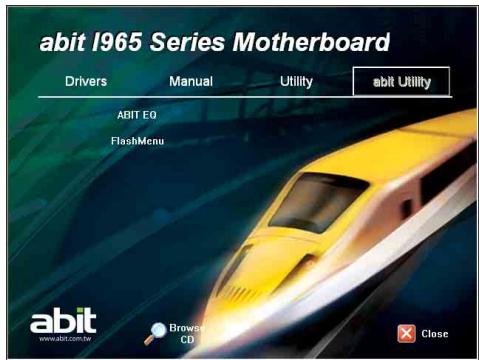
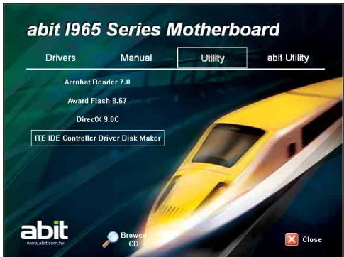
The "Driver- &- Utility CD" that came packed with this motherboard contains drivers, utilities and software applications required for its basic and advanced features.
Place the "Driver-&-Utility CD" into the CD-ROM drive in your system. The following installation auto-run screen appears. If not, browse the root directory of the CD-ROM via the File Manager, and double click the "AUTORUN" file.
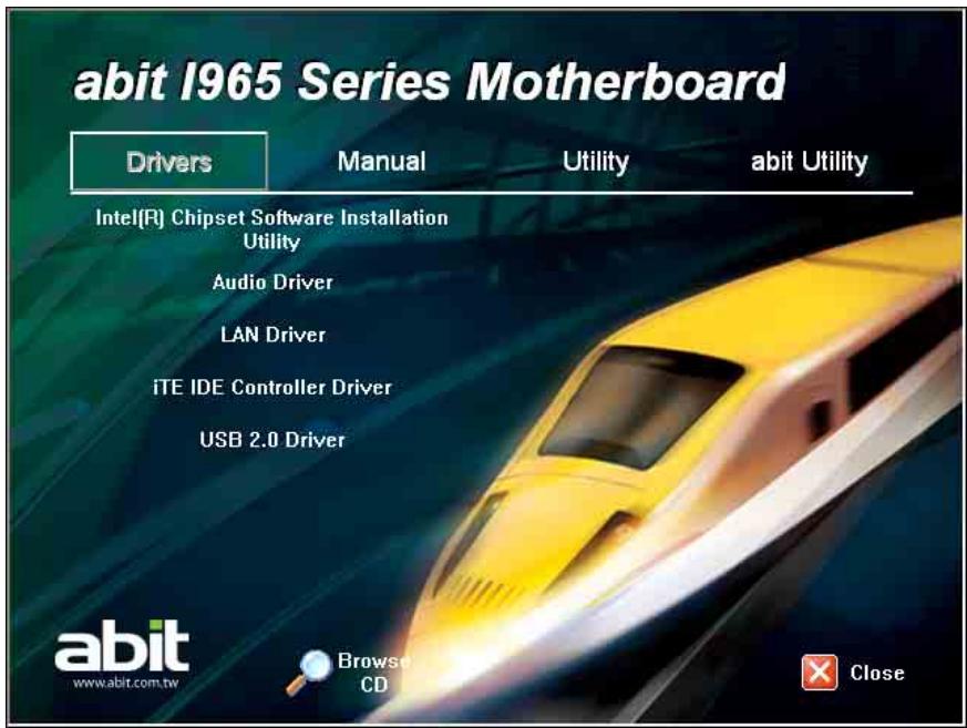
[Drivers]: Click to enter the driver installation menu.
- [Manual]: Click to enter the user's manual menu.
- [Utility]: Click to enter the utilities installation menu.
- [ABIT Utility]: Click to enter the installation menu of utilities exclusively developed by ABIT.
- [Browse CD] : Click to browse the contents of this "Driver-&-Utility CD".
- [ Close] Close]: Click to exit this installation menu.
3.1 Intel Chipset Software Installation Utility
To install this driver:
- Click on the [Drivers] tab in the installation menu screen.
- Click the [Intel Chipset Software Installation Utility] item. The installation screen appears.
- Follow the prompts on the screen to complete installation.
Intel(R) Chipset Software Installation Utility 8.0.1.1002

Welcome to the Intel(R) Chipset Software Installation Utility.
This program will install the Plug and Play components for the Intel(R) System. The following instructions are usually recommended that you exit all Windows programs before continuing:


Intel(R) Installation Frameworks
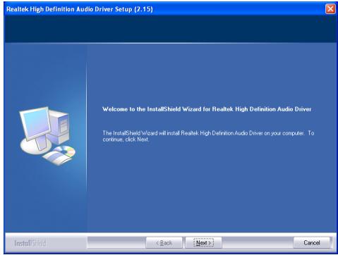
3.2 Audio Driver
To install this driver:
- Click on the [Drivers] tab in the installation menu screen.
- Click the [Audio Driver] item. The installation screen appears.
- Follow the prompts on the screen to complete installation.
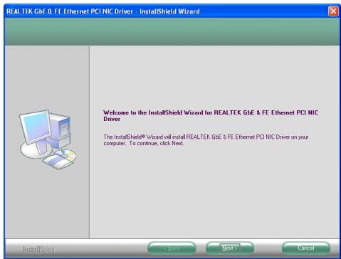
3.3 LAN Driver
To install this driver:
- Click on the [Drivers] tab in the installation menu screen.
- Click the [LAN Driver] item. The installation screen appears.
- Follow the prompts on the screen to complete installation.
3.4 iTE IDE Controller Driver
This driver is used to enable the IDE controller after having installed the Windows operating system to the hard disk connected between "IDE1" and "IDE2" connectors.
To install this driver:
- Click on the [Drivers] tab in the installation menu screen.
- Click the [iTE IDE Controller Driver] item. The installation screen appears.
- Follow the prompts on the screen to complete installation.
3.5 USB 2.0 Driver
※ There is no need to install this driver for Windows 2000 with Service Pack 4, Windows XP with Service Pack 1, or their later version.
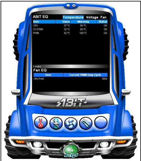
3.6 ABIT EQ (The Hardware Doctor Utility)
The ABIT EQ is a self-diagnostic system that protects PC Hardware by monitoring critical items of Power Supply Voltage, CPU & System Fans Speed, and CPU & System Temperature.
To install this utility:
- Click on the [ABIT Utility] tab in the installation menu screen.
- Click the [ABIT EQ] item. The following screen appears.
- Follow the prompts on the screen to complete installation.
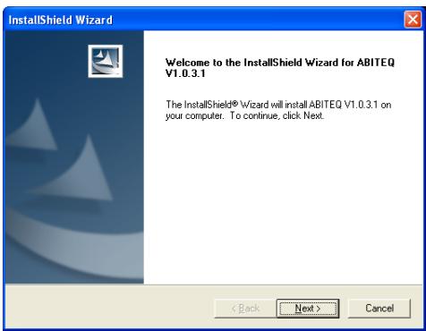
- Execute the ABIT EQ by entering the Windows Menu [Start] [All Programs] [ABIT] [ABIT EQ].
- ABIT EQ shows you the status of Voltage, Fan Speed, and Temperature readings as well.
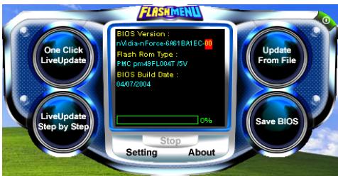
3.7 FlashMenu (BIOS Update Utility)
The FlashMenu is a utility to flash the BIOS in a more easily and quickly way.
To install this utility:
- Click on the [ABIT Utility] tab in the installation menu screen.
- Click the [FlashMenu] item. The following screen appears.

- Follow the prompts on the screen to complete installation.
- Execute the FlashMenu by entering the Windows Menu [Start] [All Programs] [ABIT] [FlashMenu].
- This FlashMenu screen appears. You can easily update the BIOS from clicking [Update From File], [One Click LiveUpdate], or [LiveUpdate Step by Step] button.
3.8 Build A Driver Disk Under Windows Environment
This utility is used to build the driver program for IDE controller into a floppy disk under Windows environment.
Connect a 3.5" floppy disk drive to the "FDC1" connector on this motherboard before entering Windows operating system.
To create a driver disk:
- Click on the [Utility] tab in the installation menu screen.
- Click the [ITE IDE Controller Driver Disk Maker] item. The installation screen appears.
- Insert one blank floppy disk to the selected floppy drive and click [Build].
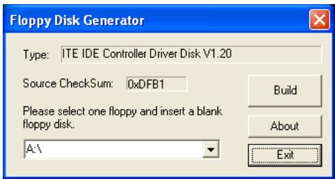
- Click [OK] to finish building the SATA Driver Disk.
- Click [Exit] to exit this utility.
3.9 Build A Driver Disk Under DOS Environment
The "Driver Disk Maker" program bundled in the Driver- &-Utility CD is a utility to build the driver program for IDE controller into a floppy disk under DOS environment. This procedure is necessary only for installing Windows operating system to the hard disk connected to "IDE1" or "IDE2" connector.
To create a driver disk:
- Before starting, connect a 3.5'' floppy disk drive to the "FDC1" connector, and connect a CD-ROM drive to your motherboard. Prepare a 3.5'' floppy disk.
- After completed all the start-up preparation for hardware setup, power on the system.
- Enter the BIOS Setup Menu by hitting <Del> key.
Enter and select the BIOS menu "Advanced BIOS Features". Configure the option "First Boot Device" to "CD-ROM" drive. Save this selection and exit BIOS setup menu by accessing the BIOS menu "Save & Exit Setup".
- Restart the system. The system will now boot from CD, and enter the ABIT Boot Manager, the following options appear3:
(0) Boot From First HDD
(1) Make Driver Disk
(2) Boot From First Floppy Drive
(3) Skip CD-ROM Boot (Try Next Boot Device)
Type <1> and hit <Enter> key. The following options appear:
(1) Make Driver Disk
(2) Exit to FreeDOS
Type <1> and hit
- The driver options appear:
(1) Generate NVRaid Floppy Disk(32bit)
(2) Intel SATA RAID Driver Disk Maker
Type the number of the action you want and hit
- Insert floppy disk to the floppy drive5. Press any key to continue.
- Now starts copying files to floppy. After completed copying, hit <n> key for not making another Driver Disk, and stop at the A:> prompt.
- Take out the Driver- &- Utility CD from the CD-ROM drive now. Restart your system6.
To install OS from IDE CD-ROM:
- Prepare a 3.5'' floppy disk drive and connect it to "FDC1" connector on this motherboard.
- Start install operating system.
- Insert this IDE driver disk into floppy disk drive when the screen instruction prompts you to install a third-party SCSI or RAID driver.
- Press <F6> key, and then follow the screen instruction to complete the installation.
This procedure is particularly necessary when you want to install operating system from a CD-ROM drive connected through "IDE1" or "IDE2" connector.
※ Make sure to select the IDE CD-ROM type for the option [First Boot device] in the BIOS Setup Menu [Advanced BIOS Features] before doing so.
4. Multilingual Quick Installation Guide
4.1 French//Guide d'Installation Rapide
| PIN | Affectation (AC'97 AUDIO) |
| 1 | MIC In |
| 2 | GND |
| 3 | MIC Power |
| 4 | NC |
| 5 | Line Out (R) |
| 6 | NC |
| 7 | NC |
| 9 | Line Out (L) |
| 10 | NC |
Interne Audioanschlüsse: [CD1], [AUX1]
![ABIT IB9 - Interne Audioanschlüsse: [CD1], [AUX1] - 1](/content/2019/10/16769/images/c783249bcd94c02103b5b96c5d816a7ebd489b586be09e458d39173cb2a3a0b6.jpg)
Conectores de paine frontal: [FPI01]
BEHTNJTTOPHbIE coeHHeHHa:
- CPUFAN1: Геанда Равьентлаятopa охлajдени CPU.
SYSFAN1:Гнздю вERTINТОРаoxJAKДENHICNTEMI.
auxFAN1: rHe3dOДЯdo6aBOuHORo BENTHJIPTOPa OxIJIaXeJTHN. - NBFAN1: I.Nézdo pour BéHTINIaTOpA OXIAJKeHnIA Northbridge.
3TNrHE3daIraBEHTNlAToPbHEaBIAKOTcNEpeMbYkAMn. HE BKNIOUATEK KOLOKnepMeBvueK E 3TN rHE3da
CoeineHnne npedne nanei: [FPI01]
![ABIT IB9 - CoeineHnne npedne nanei: [FPI01] - 1](/content/2019/10/16769/images/cd3f997aa98d7f0a3cad421f035063d4ddaeb7ab6eb43827f940cdf1ddf94ec3.jpg)
- [HLED]: CoeinnHaeTcC kαbeJem HDD LED.
[_RST]: CoemnHertcKa KaBEn M BkIIOuTeTnepeaerpyKHK. - SPKR: CoeindnHaTcC ka6eIeM CInCTeMHOrO dHnAmNka.
SLED: CoedinnaerCTc C ka6eJIem HnDikatopap PpOIOSTAOHBOKn.
PWR: CoeDnHReTcSc Ka6eJeM BbIKNIOHaTeIaHTAHIA. - PLED: CoeinnieTcC Ka6eJem HnIkaTopa NtTaHna.
Долоннichteьна Насда КаюТСВ: [FP-USB1], [FP-USB2]
YctaHObKa CPU 6JIOka TEnNOOTBODa
Tak kak cyuectbyet 60nbwo Bb6op pa3hbx TINOB
zentpaHbNbX npoecccopB (CPU) nix 6nIOKoTENNOOTbOa,
n Tak kak kakdni HNY xctahabnIbaeTcno-pa3HO.
npocIM CTOPO pnpdePKNBaTCNHTpykLNI NO yCTAHOBKE,
KOTOpBE bI haidete B KynIeHNOM Bamn NakeTe. CPU-3TO
TOnHOE 3NEKTPOHNOe YCTPOCTBO,KOTOpEO BO BPemPA60tBJbDJIenr OOrPMHOK KOJIeCteBO TpELA. PocSIM
PpHHMnATcbc 3a YCTAHOBK C npedelbHO OCTOPOXHOCTBO.
YCTaHOB MBENIOOTBOH h npOeCCOP, coeHNHTte NITAHne BENTINIATOPA OXnAeDeneHRA PC p3aBemOM CPUFAN1 HA matePHNCKO I nIATE.
UctaHOBKa ModyJeI nnamrTn
CTaTHcEe3JIeKTHpUeCTBO MOKeT NOBpeHbT 3JIeKToHHoB KOMIOHeHTb KOMIbTOpeA HIN donOHNHTeBbIX HtA. IpeT cem, KaK hauatb 3TN
ДeнТСБ, He 3a6yIbTe H36BnITbC8 O T cTahueckOrO 3NeKTpHcYBaTBA,KOPOTKO KCHyBUnCb METaJIIMHeCKOrO 3a3eMJIeHOrO rpeMetA.
CoedHHeHne yCTpoBCTB XpaHEnn daHbIX
CoeINHeHne dNcKOBoJa rN6Knx dNcKOB: [FDC1]
CoeHHeHHe JKeCTKnx DnCKOB IDE: [IDE1], [IDE2]
![ABIT IB9 - CoeHHeHHe JKeCTKnx DnCKOB IDE: [IDE1], [IDE2] - 1](/content/2019/10/16769/images/f41c4f84833eb48d2018a9514f6dd01a9ba405a582c498aceb91308ef548b32b.jpg)
CoednHeHne NocIeDobateNbHx JeeCTKHX DnCKOB ATA:[SATA1] [SATA4]
3TN pa3bembl npedHa3NaueHbI dI I coeIMHeNn PO ODHOMY nocedobateIbHOMy UcTpoIcTBy ATA h KaKdbi KaHAN C nomOuBIO Ka6eI naocedobateIbHoro ATA.
![ABIT IB9 - CoednHeHne NocIeDobateNbHx JeeCTKHX DnCKOB ATA:[SATA1] [SATA4] - 1](/content/2019/10/16769/images/5474f5f571119dfb6b993c3c564e136083f653bb2ff5b4ade8f1fa2ee339c2e7.jpg)
CoedHHnHa3dNe nHei
- Mouse: CoeHInTe c PS/2MbIb.
- Keyboard: Coeɪnɪte c PS/2 kʌbɪaTpy.
LPT1: CoedNHInATE c pinnHTepOM IINI pYHMIM YCTPOHCTBAMN, NOIDEPKINBAOUIIMN PTOKOTOKI NAPJALNBHORO B3AIMODECTBNI.
COM1: CoedInnate C BHEUHIM MODEMOM, Mbluho NIN DpyTmN CYTOBCTBAMN, NOpeKxHBauOUM INPOTOKOL NOCLEBOATEBHO 83AAMOEICTBIA. - OPT-IN1:Даннь пазьем обсянвает полкioчесни ONTOBOLOKONHOrO ka6eЯ S/PDIF OT MyIbTHmEINHbIX yCTPOINCTB.
- OUT-1:Даннь разбем обсесчиевет Бухонhoe ПОДКЛЮЧЕни ONTOВOLOKONHORO Ka6ья S/PDIF K МУЛБТМЕДИNHIM YCTРОCTВAM.
- AUDIOO1:Даньш пазьемОбсеньеетов BXOHDои BvBXODHонордкLOHENH7.1-KahalNBHOro ayniOnCIRHaJa.
- IEEE1394: CoeijnHte c yctpOJICTbAMn IpOTOKoJa
IEEE1394.
LAN1: CoeHHnTe C JOKaJIbHoI cTbIO. - USB1/USB2: CoönHInTe C TAKMIM yCTPOIcBAMN USB, KAK cKaHep, ΙιΦροBBe ένΗΜΙΝΚ, ΜΟΥΠΟΓ, ΜΙΙΙδΑ, KλαΒαπaTypa, xàβ, ΙιΦροBAr KαμερΑ, ΜΩΚΙΘΝΤι.
4.7 Estonian//Kiirpaigaldusjuhend
| Pin | Atama | Pin | Atama | |
| 1 | TPA0 + | 2 | TPA0 - | |
| 3 | Topraklama (Ground) | 4 | Topraklama (Ground) | |
| 5 | TPB0 + | 6 | TPB0 - | |
| 7 | +12V | 8 | +12V | |
| 10 | Topraklama (Ground) |
jall [ATX12V1] aaiy aay aay aay aay aay aay aay aay aay aay
2×2
:agaaa
a aaa a a a a a a a a a a a a a a a a a a a a a a a a a a a a a a a a a a a a a a a a a
Cllgall jn glwol wgl gwl n a ylyd
Aalalll jilll jilj, jld jilj jilj jilj
o gllg j ayl 1y jy 1 y 1 y 1 y 1 y 1 y 1 y 1 y 1 y
Aayalil jksjagssj
y 1
gaaa aagaae
y gill ygill ygill ygill ygill ygill ygill ygill
aaii iie 1
gill jaljll cks gai aaii ball alalw, gai jll aaii
1.
a 1 a 1 1 1 1 1 1 1 1 1 1 1 1
y
y j 1
aalil 10 gill jall
a 1
1
aaii aii iie 8y gai ygai yalalalalalalalalalalalalalalalalalalalalalalalal
yolwai a1s pS
jaii jaii jaii jaii jaii jaii jaii jaii jaii jaii jaii jaii jaii jaii jaii jaii jaii jaii jaii jaii jaii jaii jaii jaii jaii jaii jaii jaii jaii jaii jaii jaii jaii jaii jali jali jali jali jali jali jali jali jali jali jali jali jali jali jali jali jali jali jali jali jali jali jali jali jali jali jali jali jali jali jali jali jali jali jali jali jali jali jali jali jali jali jali jali
CMOS issi

Normal (Default)

Clear CMOS
0000
cmOS sul
BOS
BIOS 1234567890
a a a a a a a a a a a a a a a a a a a a a a a a a a a a a a a a a a a a a a a a a a
ydi li ydi du jia jia
.PS/2 1950:Mouse
.PS/2 E 10000000000000000000000000000000000000000000000000000000000000
Jgssy sill gj 1 j 1 LpL1 .
a a a a a a a a a a a a a a a a a a a a a a a a a a a a a a a a a a a a a a a a a a a a a a a a a a a a a a a a a a a a a a a a a
s1i7.7.1 g aal jg w g bai: AUDIO1
Jalal Jalal jajjall USB jujjll sill jilll Jusll Jusll USB jujjll jilll jusll Jusll jujjll
a aee aee aee aee aee aee aee aee aee aee aee aee aee
y jlll lllllllllllllllllllll
Clllal (CPU) yjy jlllall Clll, g jil l l j 1111111111111111111111111111111111111111
Ie aolill iic jiall,
Jusu jusu p aee annn aas yj yaae aayy o aayy aay CPUFAN1 3aay ay jx yaal aalaaa 2y yay yay aal aal
5555555555
y 11111111111111111111111111111111111111
.
Lwaw
[ATX12V1] [ATXPWR1] :ATX uio guo
2x12 yJUaI Jz aI ATX Jyulawu jzg
Ls Log [ATXPWR1]
sL sL sL sL sL sL sL sL sL sL sL sL sL sL sL sL sL sL sL sL sL sL sL sL sL sL sL sL sL sL sL sL sL sL sL sL sL sL sL sL sL sL sL sL sL sL sL sL sL sL sL
JgJioJI "USB VCC" JLS U (Ground) "Jos" JLS laB
Luslogsslo w1 "AVCC" 4wuyslj
| (AC'97LJUJS) | |
| MIC In | 1 |
| GND | 2 |
| MIC Power | 3 |
| NC | 4 |
| Line Out (R) | 5 |
| NC | 6 |
| NC | 7 |
| Line Out (L) | 9 |
| NC | 10 |
| (HD L#S) | |
| MIC2 L | 1 |
| AGND | 2 |
| MIC2 R | 3 |
| AVCC | 4 |
| FRO-R | 5 |
| MIC2_JD | 6 |
| F_IO_SEN | 7 |
| FRO-L | 9 |
| LINE2_JD | 10 |
a a 1 a b1 a b1 a b1 a b1 a b1 a b1 a b1 a b1 a b1 a b1 a b1 a b1 a b1 a b1 a b1 a b1 a b1 a b1 a b1 a b1 a b1 a b1 a b1 a b1 a b1 a b1 a b1 a b1 a b1 a b1 a b1 a b1 a b1 a b
jol cww jkpa y sl a
aui guo aubu ags yu suu u juua
.1s jw w s 8, g slk g ljwl a Jzil
aas aas
.2Jw,0d|g,du|l,lj
:JU. sW L W s, r Jr Jr Jr Jr Jr Jr
JgswwcbwcbwcbbI/Osag
S OBC = S COD + S_ BOC
LJyJswLwuygysdlo gLa yslgjw Jzo
.
aLgJyLsl aLsLgJyLsLgJyL
aS a>01g0s|jwL
Lsw sla y b u L Jy rsslo s g y sl a y
.
[IDE2].[IDE1]:IDEJdRd
[SATA1] :Serial ATA Sssdla [SATA4]
S JUaI S JUaI S aI aI aI aI aI aI aI aI aI aI aI aI aI aI aI aI aI aI aI aI aI aI aI aI aI aI aI aI aI aI aI aI aI aI aI aI aI aI aI aI aI aI aI aI aI aI aI aI aI aI aII Serial ATA oS S S S S S S S S S S S S S S S S S S S S S S S S S S S S S S S S S S S S S S S S S S S S S S S S S S S S S S S S
a c jj u
Jog PS/2 wgl:Mouse
.1s Jog PS/2 a:Keyboard
bljI JSggyjI aS yuL oBcDswuLyu LyJyL L:LPT1
Lis Log, liS go jiuu sJgo
j ASyIaOgLwLyUygSogSgLo:COM1
Lgog s guljwblj
S/PDIF sJUJ:OPT-IN1
a a 1 1 1 1 1 1 1 1 1 1 1 1 1 1 1 1
j S/PDIF JJOLJLJOLJL:OPT-OUT1
aJluiuus sla iLw,du slal oLwss aSg jyjb 2JLW
.ajus 7/1 sgs sgs/sgs jai:AUDIO1
Jog IEEE1394 Js jy sI sl slgol:IEEE1394
.
Log (LAN) 120 si aebio as:LAN1
sLgssu USB s0s:USB1/USB2
,Uuusssssssssssssssssssssssssssssssssssssssssssssssssssssssssssssssssssssssssssssssssssssssss
Lus Log oucg Suiu1Sg>
[FP-USB2].[FP-USB1]:USB
I/O, JU, aS, Lla, 0g, g>o USB Uaia cta Jz, oog Lc JI, USB Cg, g, Juaia g, la, g La, g, j, J, J, J, J, J, J, J, J, J, J, J, J, J, J, J, J, J, J, J, J, J, J, J
a a a a a a a a a a a a a a a a a a a a a a a a a a a a a a a a a a a a a a a a a a a a a a a a a a
. 1000000000000000000000000000000000000000000
sssssssssssssssssssssssssssssssssssssssssssssssssssssssssssssssssssssssssssss
LgJyRjSlo Sg CPUFAN1 JaiI JzQ a Jy
abol sla Ugjlo wai
jguols suiis/ oebq a 1g so sLw auiuys
/egwj wyy 0o o / sla/sda
jolal s1sul9 ssw uuswsuol
JSLW awwujs/1,16 as 1g w jiaobo.olgs vio S
Lw/olw alzj law
| Pin | Tugasan (AC'97 AUDIO) |
| 1 | MIC In |
| 2 | GND |
| 3 | MIC Power |
| 4 | NC |
| 5 | Line Out (R) |
| 6 | NC |
| 7 | NC |
| 9 | Line Out (L) |
| 10 | NC |
Port Kepala USB Tambahan: [FP-USB1], [FP-USB2]
JNDNNTTNNNNNNNNNNNNNNNNNNNNNNNNNNNNNNNNNNNNNNNNNNNNNNNNNNNNNNNNNNNNNNNNNNNNNNNNNNNNNNNNNNNNNNNNNNNNNNNNNNNNNNNNNNNNNNNNNNNNNNNNNNNNNNNNNNNNNNNNNNNNNNNNNNNNNNNN
nwnnnnnaaannnnnnae nnnnnnnnnae
nunnnn "GROUND" n 13 "USB VCC" nnnnnnn 4 "AVCC" vannnnn
![ABIT IB9 - Port Kepala USB Tambahan: [FP-USB1], [FP-USB2] - 1](/content/2019/10/16769/images/e9de08d9a3130bbd9505967f33374110c405c517d08c2d1d604da0a54fe13bdd.jpg)
| an | wnwthwnu (HD AUDIO) |
| 1 | MIC2 L |
| 2 | AGND |
| 3 | MIC2 R |
| 4 | AVCC |
| 5 | FRO-R |
| 6 | MIC2_JD |
| 7 | F_IO_SEN |
| 9 | FRO-L |
| 10 | LINE2_JD |
| 7531 108642 FP-USB1 FP-USB2 | 7531 108642 FP-USB1 FP-USB2 | 7531 108642 FP-USB1 FP-USB2 | 7531 108642 FP-USB1 FP-USB2 | |
| 1 | VCC | 2 | ||
| 3 | Negative Data Channel 0 | 4 | ||
| 5 | Positive Data Channel 0 | 6 | ||
| 7 | Ground | 8 | ||
| 10 |
IEEE1394: [FP-1394-1], [FP-1394-2]
nF Floppy Disk Drive: [FDC1]
IDE Hard Drives: [IDE1], [IDE2]
![ABIT IB9 - IDE Hard Drives: [IDE1], [IDE2] - 1](/content/2019/10/16769/images/c38eb8b21b5ec3b58141bba2cbb74a4098fed49791e4d1011ebeae9b3431c519.jpg)
Serial ATA Hard Disk Drives: [SATA1] ~ [SATA4]
Serial ATA Serial ATA
![ABIT IB9 - Serial ATA Hard Disk Drives: [SATA1] ~ [SATA4] - 1](/content/2019/10/16769/images/98ba11301211a8d6c7a87485a7e783b0fa5770f6c5c739dcb96860fae55aee3e.jpg)
nnaaannaaan
- Mouse: iαμινησιρι PS/2
- Keyboard: nānnuu wnuu PS/2
LPT1:
COM1: 4 - OPT-IN1: 500000000000000 S/PDIF 500000000000000 150000000000000
- OPT-OUT1: 7000000000000000 S/PDF wnuwnuu wnuwnuwnuwnuwnuwnuwnuwnuwnuwnuwnuwnuwnuwnuwnuwnuwnuwnuwnuwnuwnuwnuwnuwnuwnuwnuwnuwnuwnuwnuwnuwnuwnuwnuwnuwnuwnuwnuwnuwnuwnuwnuwnuwnuwnuwnuwnuwnuwnuwnuwnu
AUDIO1: 7.1 - IEEE1394: nuaaunnuuauuuu IEEE1394
LAN1: Local Area Network.
USB1/USB2: nuaaunu USB uunuua, unu, nanw, uww, uww, uww, uww
4.19 繁體中文
4.19.1 規格
處理器
5.1 Troubleshooting (How to Get Technical Support?)
5.1.1 Q & A
Q: Do I need to clear the CMOS before I use a new motherboard to assemble my new computer system?
A: Yes, we highly recommend that you clear the CMOS before installing a new motherboard. Please move the CMOS jumper from its default 1-2 position to 2-3 for a few seconds, and then back. When you boot up your system for the first time, follow the instructions in the user's manual to load the optimized defaults.
Q: If my system hangs when I update the BIOS or set the wrong CPU parameters, what should I do?
A: Whenever you update the BIOS or if the system hangs due to wrong CPU parameters setting, always clear CMOS jumper before booting up again.
Q: Why does the system fail to boot up again right after a mechanical power-off?
A: Please keep a 30-second interval between each mechanical power On/Off.
Q: Why does the system fail to boot up and nothing displays on the screen after I did some over-clocking or non-standard settings inside the BIOS?
A: It should not cause hardware or permanent damage to motherboard when BIOS settings were changed from default to over-clocking or non-standard status.
We suggest the following three troubleshooting methods to discharge CMOS data, recover the hardware default status, and then making the motherboard work again. There is no need to bother returning the motherboard to where you bought it from or go through an RMA process.
Step 1. Switch off the power supply unit and then switch it on again after one minute. If there is no power-switch on the power supply unit, disconnect its power cord for one minute and then reconnect.
Press and hold the key to enter the BIOS setup page to apply the correct settings.
If the situation remains the same, repeat the procedures in Step 1 for three times, or try Step 2.
Step 2. Switch off the power supply unit or disconnect the power cord. Open the chassis cover. Locate the CCMOS jumper near the button battery. Change the jumper position from default 1-2 to 2-3 for one minute to discharge the CMOS data, and then put it back to default 1-2 position.
Close the chassis and switch on the power supply unit or plug in the power cord. Press the power-on button to boot up system. If it works, hit key to enter the BIOS setup page to do the correct settings.
If the situation remains the same, try Step 3.
Step 3. The same procedure as Step 2, but while discharging the CMOS data, pull out the ATX power connectors from motherboard and remove the button battery during CMOS discharge.
Q: How to get a quick response for my request on technical support?
A: Please carry out a simple troubleshooting before sending "Technical Support Form":
System boot-up fails after the system had been assembled:
Check the motherboard's supporting specifications first to see if all the key components attached in your system can meet.
To do so, you may:
- Remove all the unnecessary add-on devices (except the CPU, VGA card, DRAM, and Power Supply), and then reboot.
- If the trouble still exists, try another VGA card of different brand/model to see if the system will start.
- If the trouble still exists, try another memory module of different brand/model.
- If the trouble still exists, try another CPU and Power Supply.
If the system runs successfully, shut it down and start re-installing the interface cards and devices that were previously installed in the system. Re-install and start the system one at a time until the system won't start.
Malfunction in the OS:
If the system hangs after resuming from S3 or some testing program, if the CPU cannot be recognized properly, if the display resolution mixed, or if a certain program cannot be executed, etc, you may:
- Upgrade the motherboard's latest BIOS version.
- Upgrade the add-on device's latest driver version.
- Check if there is any conflict in the "Control Panel/System Properties".
Q: How to fill in the "Technical Support Form"?
A: To fill in this "Technical Support Form", please refer to the following instructions:
Region: Type in your country name.
E-mail: Type in your contact E-mail information.
- First name: Type in your first name.
- Last name: Type in your last name.
- Subject: Type in the model name and the problem of your motherboard. Example 1: AA8XE and SCSI 29160 malfunction Example 2: AA8XE boot fails, POST code AF Example 3: AA8XE (system hang when S3 resume)
- Motherboard: Type in the model name and revision number of your motherboard. Example: AA8XE REV: 1.00
BIOS Version: Type in the BIOS version of your motherboard. (You can find it on the screen during the POST sequence.)
- CPU: Type in the brand name and the speed (MHz) of your CPU. (Illustrate the over-clocking status if you had done so.) Example: Intel 650 3.4GHz (OC FSB=220MHz)
- Memory brand: Type in the brand and model name of your memory module. Example: Memory brand: Kingston (KVR533D2N4/1G)
Memory size: Type in the size of your memory module. Example: 512M* 4PCS
- Memory configuration: Type in the memory configuration in BIOS setting. Example: Memory Timing: 2.5-3-3-7 @533MHz
- Graphics information: Note Graphics card's brand, model and driver version
- Graphics card: Type in the brand and model name of your graphics card. Example: ATI RADEON X850 XT PE
- Graphics driver version: Type in the driver version of your graphics card Example: Catalyst 5.12V
- Power supply maker: Type in the brand and model name of your power supply unit.
- Power supply wattage: Type in the power wattage of your power supply unit.
- Storage devices: Type in the brand and specifications of your HDD drive and quantity. Specify if it was inserted on IDE (Master or Slave) or SATA ports, including the RAID allocation status. Example 1: WD Caviar WD600 60GB (on IDE2 master), Maxtor DiamondMax 10 SATA 300GB (on SATA 3) Example 2: Maxtor DiamondMax 10 SATA 300GB *2 (on SATA 3, SATA 4 RAID 1)
- Optical devices: Type in the brand and specifications of your optical drives and quantity. Specify if it was inserted on IDE (Master or Slave) or SATA ports.
- Other devices: Indicate which add-on cards or USB devices that you absolutely sure are related to the problem. If you cannot identify the problem's origin, indicate all the add-on cards or USB devices inserted on your system. Example: AHA 29160 (on PCI 2), Sandisk Cruzer mini 256MB USB Flash-disk.
- Operating system: Indicate which OS and language version Example: Microsoft Windows XP SP2, English version Example: Microsoft Media Center Edition 2005, Korean version
- Problem description: Describe the problem of your system configuration. Indicate the steps to duplicate problem if possible.
See the next page for a blank Technical Support Form, or visit our website to fill in the form on line (http://www.abet.com.tw/page/en/contact/technical.php).
Q. Is the motherboard dead? Do I need to return it to where I bought from or go through an RMA process?
A: After you had gone through the troubleshooting procedures, yet the problem still exists, or you find an evident damage on the motherboard. Please contact our RMA center. (http://www2.abit.com.tw/page/en/contact/index.php?pFUN KEY=18000&pTITLE IMG)
5.1.2 Technical Support Form
| Region: | |
| E-mail: | |
| First name: | |
| Last Name: | |
| Subject: | |
| Motherboard: | |
| BIOS Version: | |
| CPU: | |
| Memory brand: | |
| Memory size: | |
| Memory configuration: | |
| Graphics card: | |
| Graphics driver version: | |
| Power supply maker: | |
| Power supply wattage: | |
| Storage devices: | |
| Optical devices: | |
| Other devices: | |
| Operating system: | |
| Problem description: |
5.1.3 Contact Information
Taiwan Head Office
Universal ABIT Co., Ltd.
No. 323, Yang Guang St., Neihu, Taipei, 114, Taiwan
Tel: 886-2-8751-3380
Fax: 886-2-8751-3381
Sales: sales@abit.com.tw
Marketing: market@abit.com.tw
North America, South America
Universal ABIT (USA) Corporation
2901 Bayview Drive,
Fremont, CA 94538, U.S.A.
Tel: 1-510-623-0500
Fax: 1-510-623-1092
Website: http://www.abit-usa.com
Latin America: ventas@abit-usa.com
RMA Center: http://rma.abit-usa.com
UK, Ireland
Universal ABIT UK Corporation
Unit 3, 24-26 Boulton Road, Stevenage, Herts SG1 4QX, UK
Tel: 44-1438-228888
Fax: 44-1438-226333
for technical support: technical@abitcomputer.co.uk
for RMA no direct technical support: returns@abitcomputer.co.uk
Tel: 44-1438-362088
Germany and Benelux (Belgium, Netherlands, Luxembourg), France, Italy, Spain, Portugal, Greece, Denmark, Norway, Sweden, Finland, Switzerland
Universal ABIT NL B.V.
Jan van Riebeeckweg 15, 5928LG, Venlo, The Netherlands
Tel: 31-77-3204428
Fax: 31-77-3204420
Austria, Czech, Romania, Bulgaria, Slovakia, Croatia, Bosnia, Serbia, Macedonia, Slovenia
Universal ABIT Austria Computer GmbH
Schmalbachstrasse 5, A-2201 Gerasdorf / Wien, Austria
Tel: 43-1-7346709
Fax: 43-1-7346713
Contact: office@abit-austria.at
Website: http://www.abit-austria.at
Shanghai
Universal ABIT (Shanghai) Co. Ltd.
FL 19 Xuhui Yuan BLOG NO.1089
ZhongShan s 2 RD, ShangHai 200030
The People's Republic of China
Tel: (86-21) 54102211
Fax: (86-21) 54104791
Website: http://www.abit.com.cn
Poland
Universal ABIT Poland (Rep. office)
Strzegomska 310/2, 54-432 Wroclaw
Tel: +48-71-718-12-39
Fax: +48-71-718-12-38
Contact: Grzegorz Morgiel
Turkey
Universal ABIT Turkey (Rep. office)
Tel: 90 532 211 6860
abit
UNIVERSAL ABIT Co., Ltd.
http://www.ubit.com.tw

- IB9
- Copyright and Warranty Notice
- Hardware Setup 1-1
- BIOS Setup 2-1
- Driver & Utility 3-1
- Multilingual Quick Installation Guide 4-1
- Hardware Setup
- Specifications
- CPU
- Chipset
- Memory
- LAN
- Audio
- Serial ATA
- Expansion Slots
- Internal I/O Connectors
- Rear Panel I/O
- ABIT Engineered
- RoHS
- Miscellaneous
- Choosing a Computer Chassis
- Installing Motherboard
- To install this motherboard:
- Checking Jumper Settings
- CMOS Memory Clearing Header and Backup Battery
- To clear the CMOS memory and load in the default values:
- CMOS Backup Battery:
- To renew the backup battery:
- CAUTION:
- Wake-up Header
- USB-PWR1:
- USB-PWR2:
- Connecting Chassis Components
- ATX Power Connectors
- ATX 24-Pin Power Connector:
- ATX 12V 4-Pin Power Connector:
- Front Panel Switches & Indicators Headers
- FAN Power Connectors
- Installing Hardware
- CPU Socket 775
- DDR2 Memory Slots
- To install system memory:
- Connecting Peripheral Devices
- Floppy and IDE Disk Drive Connectors
- Serial ATA Connectors
- To connect SATA device:
- Additional USB 2.0 Port Headers
- Internal Audio Connectors
- Front Panel Audio Connection Header
- Driver Configuration for AC'97 audio connection:
- PCI and PCI Express X16, X1 Slots
- Onboard Status Display
- Power Source Indicators
- Connecting Rear Panel I/O Devices
- BIOS Setup
- PRESS DEL TO ENTER SETUP
- SoftMenu Setup
- Brand Name
- Frequency
- Cache Size
- CPU Operating Speed
- User Define:
- External Clock
- Multiplier Factor
- - Estimated New CPU Clock
- PCI Express Frequency
- Voltages Control
- Standard CMOS Features
- Date (mm:dd:yy)
- Time (hh:mm:ss)
- IDE Channel 1 Master, IDE Channel 2 Master, IDE Channel 3 Master, IDE Channel 4 Master
- Base Memory
- Extended Memory
- Total Memory
- Advanced BIOS Features
- CPU L3 Cache
- Hyper-Threading Technology
- Quick Power On Self Test
- Thermal Management
- TM2 Bus Ratio
- TM2 Bus VID
- Limit CPUID MaxVal
- C1E Function
- Execute Disable Bit
- Virtualization Technology
- EIST Function
- Advanced Chipset Features
- DRAM Timing Selectable
- PCI Express Slot 1 / PCI Express Slot 2 / PCI Express Slot 3
- PCI-E Compliancy Mode
- Back to Advanced Chipset Features Setup Menu
- Init Display First
- Integrated Peripherals
- OnChip IDE Device
- IDE Bus Master
- OnChip USB Controller
- USB 2.0 Controller
- USB Keyboard Support
- - USB Mouse Support
- OnChip Audio Controller
- Floppy Disk Controller
- Onboard PCI Device
- IDE Controller
- Network Controller
- - Invoke Boot Agent
- Power Management Setup
- ACPI Suspend Type
- Resume by USB from S3
- Power Button Function
- CPU THRM-Throttling
- Wake-Up by PME# of PCI
- Wake-Up by Onboard LAN
- Wake-Up by Alarm
- - Date (of Month) Alarm
- Time (hh:mm:ss) Alarm
- POWER ON Function
- KB Power ON Password
- Hot Key Power ON
- Restore On AC Power Loss
- PnP/PCI Configurations
- Resources Controlled By
- - IRQ Resources
- PCI/VGA Palette Snoop
- PC Health Status
- ABIT FanEQ Control
- CPU FanEQ Control
- FanEQ Target Temp
- FanEQ Temp. Tolerance
- FanEQ Start Control
- FanEQ Stop Control
- Back to PC Health Status Setup Menu
- All Voltages, Fans Speed and Thermal Monitoring
- Load Fail-Safe Defaults
- Load Optimized Defaults
- Set Password
- Save & Exit Setup
- Exit Without Saving
- Driver & Utility
- Intel Chipset Software Installation Utility
- To install this driver:
- Intel(R) Chipset Software Installation Utility 8.0.1.1002
- Audio Driver
- LAN Driver
- iTE IDE Controller Driver
- USB 2.0 Driver
- ABIT EQ (The Hardware Doctor Utility)
- To install this utility:
- FlashMenu (BIOS Update Utility)
- Build A Driver Disk Under Windows Environment
- To create a driver disk:
- Build A Driver Disk Under DOS Environment
- To install OS from IDE CD-ROM:
- Multilingual Quick Installation Guide
- French//Guide d'Installation Rapide
- Interne Audioanschlüsse: [CD1], [AUX1]
- BEHTNJTTOPHbIE coeHHeHHa:
- CoeineHnne npedne nanei: [FPI01]
- Долоннichteьна Насда КаюТСВ: [FP-USB1], [FP-USB2]
- YctaHObKa CPU 6JIOka TEnNOOTBODa
- UctaHOBKa ModyJeI nnamrTn
- CoedHHeHne yCTpoBCTB XpaHEnn daHbIX
- CoeINHeHne dNcKOBoJa rN6Knx dNcKOB: [FDC1]
- CoeHHeHHe JKeCTKnx DnCKOB IDE: [IDE1], [IDE2]
- CoednHeHne NocIeDobateNbHx JeeCTKHX DnCKOB ATA:[SATA1] [SATA4]
- CoedHHnHa3dNe nHei
- Estonian//Kiirpaigaldusjuhend
- Aayalil jksjagssj
- CMOS issi
- ydi li ydi du jia jia
- y jlll lllllllllllllllllllll
- 5555555555
- Lwaw
- jol cww jkpa y sl a
- a c jj u
- abol sla Ugjlo wai
- Port Kepala USB Tambahan: [FP-USB1], [FP-USB2]
- IEEE1394: [FP-1394-1], [FP-1394-2]
- nF Floppy Disk Drive: [FDC1]
- IDE Hard Drives: [IDE1], [IDE2]
- Serial ATA Hard Disk Drives: [SATA1] ~ [SATA4]
- nnaaannaaan
- 繁體中文
- 規格
- 處理器
- Troubleshooting (How to Get Technical Support?)
- Q & A
- System boot-up fails after the system had been assembled:
- Malfunction in the OS:
- Q: How to fill in the "Technical Support Form"?
- Is the motherboard dead? Do I need to return it to where I bought from or go through an RMA process?
- Technical Support Form
- Contact Information
- Taiwan Head Office
- Universal ABIT Co., Ltd.
- North America, South America
- Universal ABIT (USA) Corporation
- UK, Ireland
- Universal ABIT UK Corporation
- Universal ABIT NL B.V.
- Austria, Czech, Romania, Bulgaria, Slovakia, Croatia, Bosnia, Serbia, Macedonia, Slovenia
- Universal ABIT Austria Computer GmbH
- Shanghai
- Universal ABIT (Shanghai) Co. Ltd.
- Poland
- Universal ABIT Poland (Rep. office)
- Turkey
- Universal ABIT Turkey (Rep. office)
- abit
Brand : ABIT
Model : IB9
Category : Motherboard