FATAL1TY F-I90HD - Motherboard ABIT - Free user manual and instructions
Find the device manual for free FATAL1TY F-I90HD ABIT in PDF.

User questions about FATAL1TY F-I90HD ABIT
0 question about this device. Answer the ones you know or ask your own.
Ask a new question about this device
Download the instructions for your Motherboard in PDF format for free! Find your manual FATAL1TY F-I90HD - ABIT and take your electronic device back in hand. On this page are published all the documents necessary for the use of your device. FATAL1TY F-I90HD by ABIT.
USER MANUAL FATAL1TY F-I90HD ABIT
For more information:
WWW.ABIT.COM.TW
WWW.FATALITY.COM
F-I90HD
User's Manual
English + Multilingual QIG
P/N: 4310-0000-83
Rev. 2.00, April 2007
Copyright and Warranty Notice
The information in this document is subject to change without notice and does not represent a commitment on part of the vendor, who assumes no liability or responsibility for any errors that may appear in this manual.
No warranty or representation, either expressed or implied, is made with respect to the quality, accuracy or fitness for any particular part of this document. In no event shall the manufacturer be liable for direct, indirect, special, incidental or consequential damages arising from any defect or error in this manual or product.
Product names appearing in this manual are for identification purpose only and trademarks and product names or brand names appearing in this document are the property of their respective owners.
This document contains materials protected under International Copyright Laws. All rights reserved. No part of this manual may be reproduced, transmitted or transcribed without the expressed written permission of the manufacturer and authors of this manual.
If you do not properly set the motherboard settings, causing the motherboard to malfunction or fail, we cannot guarantee any responsibility.
The Fatality name, Fatality logos and the Fatality likeness are trademarks of Fatality, Inc. All rights reserved. Built to Kill is a trademark of PWX, LLC.
© 2007 Universal ABIT Co., Ltd.
All other trademarks are the property of their respective owners.
The Following Information is Only for EU-member States:

Directive 2002/96/EC on Waste Electrical and Electronic Equipment (WEEE): The use of the symbol indicates that this product may not be treated as household waste. By Ensuring this product is disposed of correctly, you will help prevent potential negative consequences for the environment and human health, which could otherwise be cause by inappropriate waste handling of this product. For more detailed information about recycling of this product, please contact your local city office, your household waste disposal service or the shop where you purchased the product.
Introduction
FATALITY STORY
Who knew that at age 19, I would be a World Champion PC gamer. When I was 13, I actually played competitive billiards in professional tournaments and won four or five games off guys who played at the highest level. I actually thought of making a career of it, but at that young age situations change rapidly. Because I've been blessed with great hand-eye coordination and a grasp of mathematics (an important element in video gaming) I gravitated to that activity.

GOING PRO
I started professional gaming in 1999 when I entered the CPL (Cyberathlete Professional League) tournament in Dallas and won 4,000 for coming in third place. Emerging as one of the top players in the United States, a company interested in sponsoring me flew me to Sweden to compete against the top 12 players in the world. I won 18 straight games, lost none, and took first place, becoming the number one ranked Quake III player in the world in the process. Two months later I followed that success by traveling to Dallas and defending my title as the world's best Quake III player, winning the40,000 grand prize. Since then I've traveled the globe to compete against the best in the world, winning prizes and acclaim, including the 2005 CPL World Tour Championship in New York City for a $150,000 first place finish.
LIVIN' LARGE
Since my first big tournament wins, I have been a "Professional Cyberathlete", traveling the world and livin' large with lots of International media coverage on outlets such as MTV, ESPN and G4TV to name only a few. It's unreal - it's crazy. I'm living a dream by playing video games for a living. I've always been athletic and took sports like hockey and football very seriously, working out and training hard. This discipline helps me become a better gamer and my drive to be the best has opened the doors necessary to become a professional.
A DREAM
Now, another dream is being realized – building the ultimate gaming computer, made up of the best parts under my own brand. Quality hardware makes a huge difference in competitions...a couple more frames per second and everything gets really nice. It's all about getting the computer processing faster and allowing more fluid movement around the maps.
My vision for Fatal1ty hardware is to allow gamers to focus on the game without worrying about their equipment, something I've preached since I began competing. I don't want to worry about my equipment. I want it to be there – over and done with - so I can focus on the game. I want it to be the fastest and most stable computer equipment on the face of the planet, so quality is what Fatal1ty brand products will represent.
FATALITY PARTNERS
This is just the beginning. We're already in development for several new products, and I'm really grateful to all my Fatal1ty partners for helping make my dreams a reality.
I know there is a business side to all of this, but for me the true reward is making products that are so good I can win with them – and making them available to fellow gamers. Gaming is my life, and many fellow gamers around the world are also some of my best friends, so giving back to the gaming community is really important to me.

Johnathan "Fatality" Wendel
1. Hardware Setup 1-1
1.1 Specifications 1-1
1.2 Motherboard Layout 1-2
1.3 Choosing a Computer Chassis 1-3
1.4 Installing Motherboard 1-3
1.5 Checking Jumper Settings 1-4
1.5.1 CMOS Memory Clearing Header and Backup Battery 1-4
1.6 Connecting Chassis Components 1-6
1.6.1 ATX Power Connectors 1-6
1.6.2 Front Panel Switches & Indicators Headers 1-7
1.6.3 FAN Power Connectors 1-7
1.7 Installing Hardware 1-8
1.7.1 CPU Socket 775 1-8
1.7.2 DDR2 Memory Slots 1-10
1.8 Connecting Peripheral Devices 1-11
1.8.1 Floppy and IDE Disk Drive Connectors 1-11
1.8.2 Serial ATA Connectors 1-12
1.8.3 Additional USB 2.0 Port Headers 1-13
1.8.4 Internal Audio Connector 1-14
1.8.5 Front Panel Audio Connection Header 1-14
1.8.6 PCI and PCI Express X16, X1 Slots 1-16
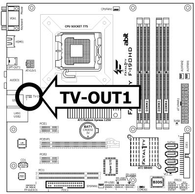
1.8.7 TV-OUT Header 1-16
1.9 Onboard Indicators and Buttons 1-17
1.9.1 LED Indicators 1-17
1.10 Connecting Rear Panel I/O Devices 1-18
2. BIOS Setup 2-1
2.1 SoftMenu Setup 2-2
2.2 Standard CMOS Features 2-3
2.3 Advanced BIOS Features 2-6
2.4 Advanced Chipset Features 2-9
2.5 Integrated Peripherals 2-10
2.6 Power Management Setup 2-13
2.7 PnP/PCI Configurations 2-15
2.8 PC Health Status 2-16
2.9 Load Fail-Safe Defaults.. 2-18
2.10 Load Optimized Defaults 2-18
2.11 Set Password 2-18
2.12 Save & Exit Setup 2-18
2.13 Exit Without Saving 2-18
3. Driver & Utility 3-1
3.1 CD-ROM AUTORUN 3-1
3.2 ATi South Bridge Driver 3-2
3.3 Microsoft.NET Framework 3-2
3.4 ATi VGA Driver 3-3
3.5 Realtek LAN Driver 3-3
3.6 Realtek Audio Driver (ATi HDMI) 3-4
3.7 ATi RAID Driver 3-6
3.8 USB 2.0 Driver 3-6
3.9 abit EQ 3-7
3.10 FlashMenu (BIOS Update Utility) 3-8
3.11 SATA RAID Driver (for Windows Vista) 3-9
3.12 SATA RAID Driver (for Windows XP, 2003, or 2000) 3-9
4. Multilingual Quick Installation Guide 4-1
4.1 Français//Guide d'Installation Rapide 4-1
4.2 Deutsch//Kurze Installationsanleitung 4-2
4.3 Italiano//Guida all'installazione rapida 4-3
4.4 Espanol//Guía rápida de instalación 4-4
4.5 Portugues//Guia de instalação rápida 4-5
4.6 Pyccn//KpaTkoe pyKOBOCTBO no yCTaHOBKe 4-6
4.7 Eesti//Kiirpaigaldusjuhend 4-7
4.8 Latviski//Atras instalëšanas instrukcija 4-8
4.9 Lietuviu//Trumpas instaliavimo vadovas 4-9
4.10 Polski//Instrukcja szybkiej instalacji 4-10
4.11 Magyar//Gyorstelepitési utmutató 4-11
4.12 Türkç//Hizl Kurulum Kilavuzu 4-12
4.13 UJgO UJgU JUJ UJU UJU UJU
4.14 /Jrws// Jorwosu wS
4.15 日本語//ケイククインスローガイド 4-15
4.16 韩国..//..
4.17 Bahasa Malaysia//Panduan Pemasangan Ringkas 4-17
4.18//nuiyua
4.19繁體中交 4-19
5.1 Troubleshooting (How to Get Technical Support?) 5-1
5.1.1 Q & A 5-1
5.1.2 Technical Support Form 5-4
5.1.3 Contact Information 5-5
1. Hardware Setup
1.1 Specifications
CPU
Designed for Intel Dual Core LGA775 processor with 1066/800MHz FSB
Support Intel Core 2 Extreme, Core 2 Quad, Core 2 Duo, Pentium EE, Pentium D, Pentium Dual Core, and Pentium 4 Processor
Chipset
NB:ATI Radeon Xpress 1250
- SB: ATI SB600
Memory
4x 240-pin DIMM slots support maximum memory capacity up to 16GB
Supports Dual Channel DDR2 800/667/533 Un-buffered ECC/Non-ECC memory
Graphics
- ATI Radeon Xpress 1250 on-chip (Radeon X700-based 2D/3D graphics)
HDMI
Support HDMI
Support High Definition Video Output
Support 7.1-channel HD audio
LAN
- Onboard PCIE Gigabit LAN
Audio
- Onboard 7.1-channel HD audio
Serial ATA
- 4x SATA 3Gb/s supports SATA RAID 0, 1, and 0 + 1
Expansion Slots
1x PCI-E X16 slot
- 2x PCI-E X1 slots
- 1x PCI slot
Internal I/O Connectors
- 1x Floppy port
1x Ultra ATA 133 IDE connector
4x SATA 3Gb/s connectors - 3x USB 2.0 headers
1x FP-Audio header
1x CD-In connector - 1x TV-OUT header
Rear Panel I/O
- 1x PS/2 Keyboard connector
1x PS/2 Mouse connector - 1x VGA connector
1x HDMI connector
1x Optical S/PDIF Out connector - 1x7.1-channel Audio connector
4x USB 2.0 connectors
1x RJ-45 Gigabit LAN connector
abit Engineered
- abit SoftMenu™ Technology
RoHS
100% Lead-free process and RoHS compliant
Miscellaneous
- Micro ATX form factor (244mm x 244mm)
※ Specifications and information contained herein are subject to change without notice.
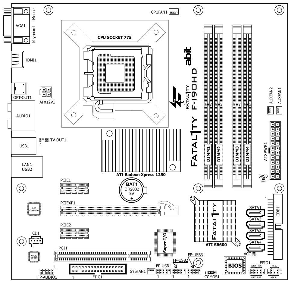
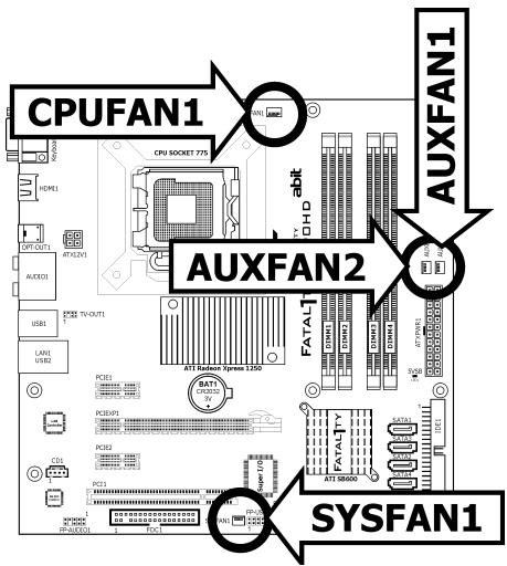
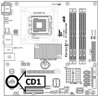
1.2 Motherboard Layout
1.3 Choosing a Computer Chassis
- Choose a chassis big enough to install this motherboard.
- As some features for this motherboard are implemented by cabling connectors on the motherboard to indicators and switches or buttons on the chassis, make sure your chassis supports all the features required.
- If there is a possibility of adopting some more hard drives, make sure your chassis has sufficient power and space for them.
- Most chassis have alternatives for I/O shield located at the rear panel. Make sure the I/O shield of the chassis matches the I/O port configuration of this motherboard. You can find an I/O shield specifically designed for this motherboard in its package.
1.4 Installing Motherboard
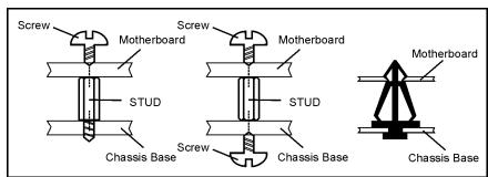
Most computer chassis have a base with many mounting holes to allow the motherboard to be securely attached, and at the same time, prevent the system from short circuits. There are two ways to attach the motherboard to the chassis base: (1) with studs, or (2) with spacers.
Basically, the best way to attach the board is with studs. Only if you are unable to do this
should you attach the board with spacers. Line up the holes on the board with the mounting holes on the chassis. If the holes line up and there are screw holes, you can attach the board with studs. If the holes line up and there are only slots, you can only attach with spacers. Take the tip of the spacers and insert them into the slots. After doing this to all the slots, you can slide the board into position aligned with slots. After the board has been positioned, check to make sure everything is OK before putting the chassis back on.

Always power off the computer and unplug the AC power cord before adding or removing any peripheral or component. Failing to so may cause severe damage to your motherboard and/or peripherals. Plug in the AC power cord only after you have carefully checked everything.
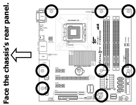
To install this motherboard:
- Locate all the screw holes on the motherboard and the chassis base.
- Place all the studs or spacers needed on the chassis base and have them tightened.
- Face the motherboard's I/O ports toward the chassis's rear panel.
- Line up all the motherboard's screw holes with those studs or spacers on the chassis.
- Install the motherboard with screws and have them tightened.
※ To prevent shorting the PCB circuit, please REMOVE the metal studs or spacers if they are already fastened on the chassis base and are without mounting-holes on the motherboard to align with.
1.5 Checking Jumper Settings
- For a 2-pin jumper, plug the jumper cap on both pins will make it CLOSE (SHORT). Remove the jumper cap, or plug it on either pin (reserved for future use) will leave it at OPEN position.
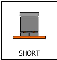
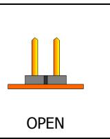
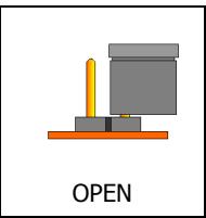
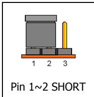
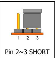
- For 3-pin jumper, pin 1 2 or pin 2 3 can be shorted by plugging the jumper cap in.
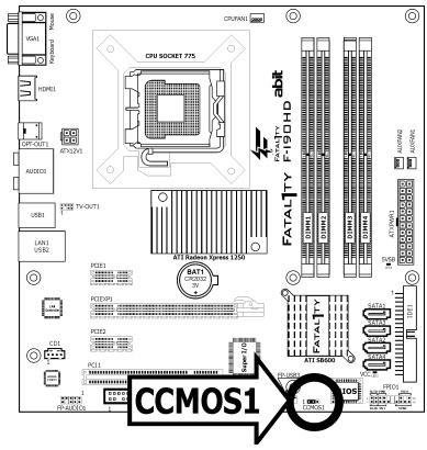
1.5.1 CMOS Memory Clearing Header and Backup Battery
The time to clear the CMOS memory occurs when (a) the CMOS data becomes corrupted, (b) you forgot the supervisor or user password preset in the BIOS menu, (c) you are unable to boot-up the system because the CPU ratio/clock was incorrectly set in the BIOS menu, or (d) whenever there is modification on the CPU or memory modules.
This header uses a jumper cap to clear the CMOS memory and have it reconfigured to the default values stored in BIOS.
- Pins 1 and 2 shorted (Default): Normal operation.
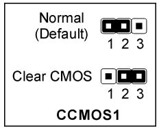
- Pins 2 and 3 shorted: Clear CMOS memory.
To clear the CMOS memory and load in the default values:
- Power off the system.
- Set pin 2 and pin 3 shorted by the jumper cap. Wait for a few seconds. Set the jumper cap back to its default settings --- pin 1 and pin 2 shorted.
- Power on the system.
- For incorrect CPU ratio/clock settings in the BIOS, press
key to enter the BIOS setup menu right after powering on system. - Set the CPU operating speed back to its default or an appropriate value.
- Save and exit the BIOS setup menu.
CMOS Backup Battery:
An onboard battery saves the CMOS memory to keep the BIOS information stays on even after disconnected your system with power source. Nevertheless, this backup battery exhausts after some five years. Once the error message like "CMOS BATTERY HAS Failed" or "CMOS checksum error" displays on monitor, this backup battery is no longer functional and has to be renewed.
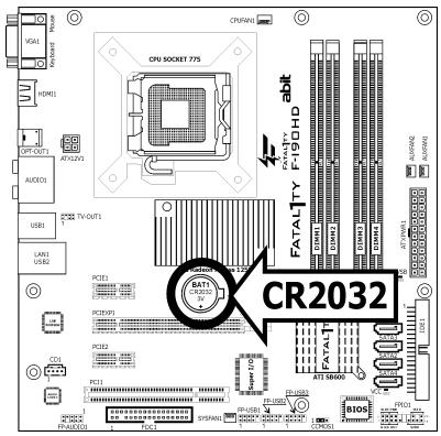
To renew the backup battery:
- Power off the system and disconnect with AC power source.
- Remove the exhausted battery.
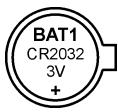
- Insert a new CR2032 or equivalent battery. Pay attention to its polarity. The "+" side is its positive polarity.
- Connect AC power source and power on the system.
- Enter the BIOS setup menu. Reconfigure the setup parameters if necessary.
CAUTION:
Danger of explosion may arise if the battery is incorrectly renewed.
Renew only with the same or equivalent type recommended by the battery manufacturer.
※ Dispose of used batteries according to the battery manufacturer's instructions.
1.6 Connecting Chassis Components
1.6.1 ATX Power Connectors
These connectors provide the connection from an ATX power supply. As the plugs from the power supply fit in only one orientation, find the correct one and push firmly down into these connectors.
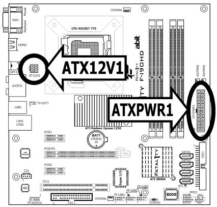
ATXPWR1: ATX 24-Pin Power Connector
The power supply with 20-pin or 24-pin cables can both be connected to this 24-pin connector. Connect from pin-1 for either type. However, a 20-pin power supply may cause the system unstable or even unbootable for the sake of insufficient electricity. A minimum power of 300W or higher is recommended.
ATX12V1: ATX 12V 4-Pin Power Connector
This connector supplies power to CPU. The system will not start without connecting power to this one.
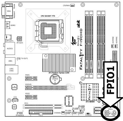
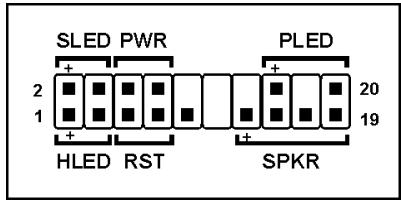
1.6.2 Front Panel Switches & Indicators Headers
This header is used for connecting switches and LED indicators on the chassis front panel.
Watch the power LED pin position and orientation. The mark "+" align to the pin in the figure below stands for positive polarity for the LED connection. Please pay attention when connecting these headers. A wrong orientation will only result in the LED not lighting, but a wrong connection of the switches could cause system malfunction.
HLED (Pin 1, 3):
Connects to the HDD LED cable of chassis front panel.
RST (Pin 5, 7):
Connects to the Reset Switch cable of chassis front panel.
SPKR (Pin 13, 15, 17, 19):
Connects to the System Speaker cable of chassis.
- SLED (Pin 2, 4):
Connects to the Suspend LED cable (if there is one) of chassis front panel.
PWR (Pin 6, 8):
Connects to the Power Switch cable of chassis front panel.
PLED (Pin 16, 18, 20):
Connects to the Power LED cable of chassis front panel.
1.6.3 FAN Power Connectors
These connectors each provide power to the cooling fans installed in your system.
- CPUFAN1: CPU Fan Power Connector
- SYSFAN1: System Fan Power Connector
- AUXFAN1~2: Auxiliary Fan Power Connector
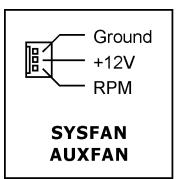
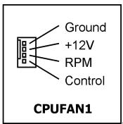
These fan connectors are not jumpers. DO NOT place jumper caps on these connectors.
1.7 Installing Hardware
※ DO NOT scratch the motherboard when installing hardware. An accidental scratch of a tiny surface-mount component may seriously damage the motherboard.
※ In order to protect the contact pins, please pay attention to these notices:
- A maximum 20 cycles of CPU installation is recommended.
- Never touch the contact pins with fingers or any object.
- Always put on the cap when the CPU is not in use.
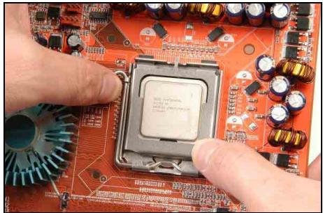
1.7.1 CPU Socket 775
The installation procedures vary with different types of CPU fan-and-heatsink assembly. The one shown here is served for demo only. For detailed information on how to install the one you bought, refer to its installation guidelines.
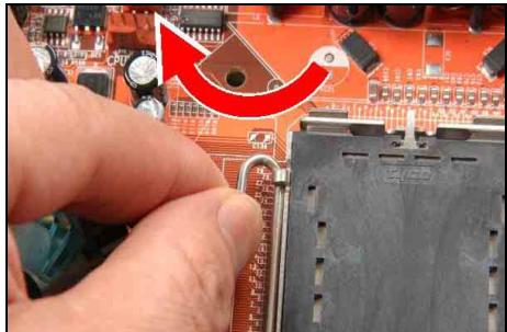
1. Place the board so that the lever-hook of the socket is on your left side. Use your left thumb and forefinger to hold the lever hook, pull it away from the retention tab. Rotate the lever to fully open position.
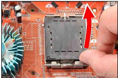
2. Use your right-thumb to raise the load plate. Lift it up to fully open position.
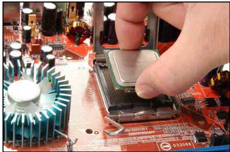
3. Use your right thumb and forefinger to grasp the CPU package. Be sure to grasp on the edge of the substrate, and face the Pin-1 indicator toward the bottom-left side. Aim at the socket and place the CPU package vertical down into the socket.
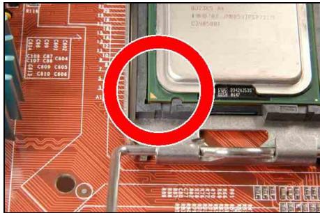
4. Visually inspect if the CPU is seated well into the socket. The alignment key must be located in the notch of package.
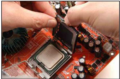
- Use your left hand to hold the load plate, and use your right thumb to peel the cap off.
The cap plays an important role in protecting contact pins. In order to prevent bent pin, PUT ON the cap after operation or testing.
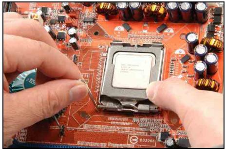
- Lower the plate onto the CPU package. Engage the load lever while gently pressing down the load plate.
- Secure the lever with the hook under retention tab.
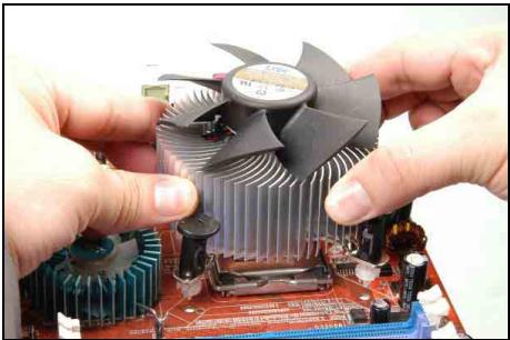
- Place the heatsink and fan assembly onto the socket. Align the four fasteners toward the four mounting holes on the motherboard.
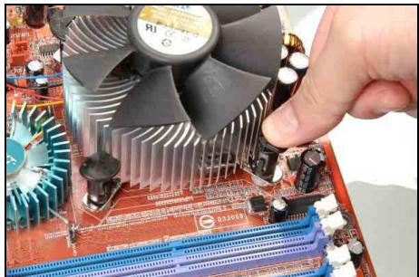
- Press each of the four fasteners down into the mounting holes. Rotate the fastener clock-wise to lock the heatsink and fan assembly into position.
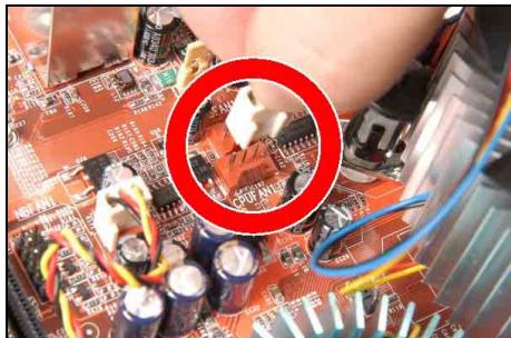
- Attach the four-pin power plug from the heatsink and fan assembly to the CPU FAN connector.
A higher fan speed will be helpful for better airflow and heat-dissipation. Nevertheless, stay alert to not touch any heatsink since a high temperature generated by the working system is still possible.
1.7.2 DDR2 Memory Slots
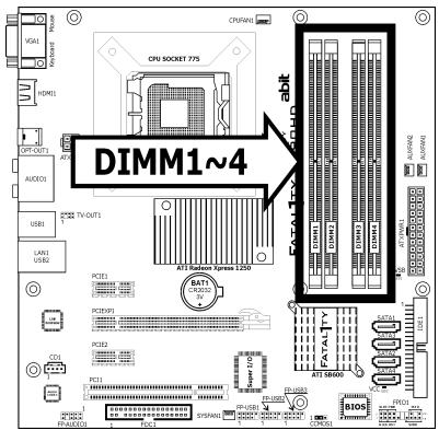
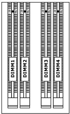
To reach the performance of Dual Channel DDR2, the following rules must be obeyed:
For a 2-DIMM dual-channel installation:
Populate DIMM modules of the same type and size on slots [DIMM1] + [DIMM3], or slots [DIMM2] + [DIMM4].
For a 4-DIMM dual-channel installation:
Populate 2 DIMM modules of the same type and size on slots [DIMM1] + [DIMM3], and another 2 DIMM modules of the same type and size on slots [DIMM2] + [DIMM4].
[DIMM1] and [DIMM3] slots are made of the same color.
[DIMM2] and [DIMM4] are made of another same color.
Usually there is no hardware or BIOS setup required after adding or removing memory modules, but you will have to clear the CMOS memory first if any memory module related problem occurs.
This motherboard does not support DDR2 memory modules of X4 device width.
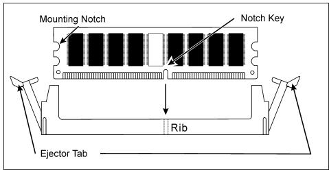
To install system memory:
- Power off the computer and unplug the AC power cord before installing or removing memory modules.
- Locate the DIMM slot on the board.
- Hold two edges of the DIMM module carefully, keep away from touching its connectors.
- Align the notch key on the module with the rib on the slot.
- Firmly press the module into the slots until the ejector tabs at both sides of the slot automatically snap into the mounting notch. Do not force the DIMM module in with extra force as the DIMM module only fits in one direction.
- To remove the DIMM modules, push the two ejector tabs on the slot outward simultaneously, and then pull out the DIMM module.
Static electricity can damage the electronic components of the computer or optional boards. Before starting these procedures, ensure that you are discharged of static electricity by touching a grounded metal object briefly.
1.8 Connecting Peripheral Devices
1.8.1 Floppy and IDE Disk Drive Connectors
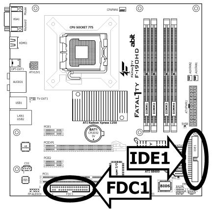
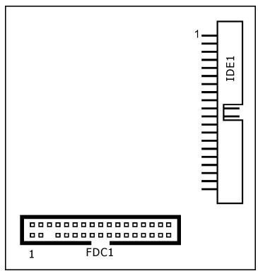
The FDC1 connector connects up to two floppy drives with a 34-wire, 2-connector floppy cable. Connect the single end at the longer length of ribbon cable to the FDC1 on the board, the two connectors on the other end to the floppy disk drives connector. Generally you need only one floppy disk drive in your system.
The red line on the ribbon cable must be aligned with pin-1 on both the FDC1 port and the floppy connector.
Each of the IDE port connects up to two IDE drives at Ultra ATA/100 mode by one 40-pin, 80-conductor, and 3-connector Ultra ATA/66 ribbon cables.
Connect the single end (blue connector) at the longer length of ribbon cable to the IDE port of this board, the other two ends (gray and black connector) at the shorter length of the ribbon cable to the connectors of your hard drives.
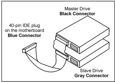
※ Make sure to configure the "Master" and "Slave" relation before connecting two drives by one single ribbon cable. The red line on the ribbon cable must be aligned with pin-1 on both the IDE port and the hard-drive connector.
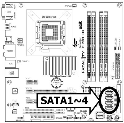
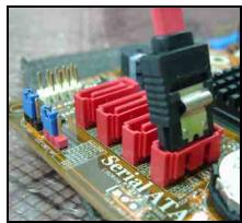
1.8.2 Serial ATA Connectors
Each SATA connector serves as one single channel to connect one SATA device by SATA cable.
The RAID 0/1/0+1 configuration is also possible by the combination of disk arrays through these SATA connectors:
For more information on how to configure the function mode for SATA, please refer to the item "OnChip SATA Mode" in the BIOS setup menu of "OnChip IDE Device".
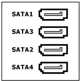
To connect SATA device:
- Attach either end of the signal cable to the SATA connector on motherboard. Attach the other end to the SATA device.
- Attach the SATA power cable to the SATA device and connect the other end from the power supply.
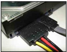
The motherboard in this photo is served for DEMO only, and may not be the same type or model as the one described in this user's manual.
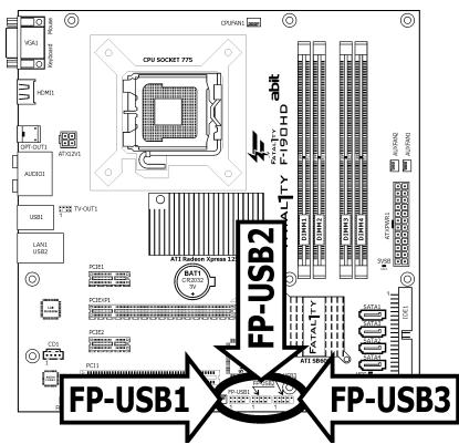
1.8.3 Additional USB 2.0 Port Headers
Each header supports 2x additional USB 2.0 ports by connecting bracket or cable to the rear I/O panel or the front-mounted USB ports of your chassis.
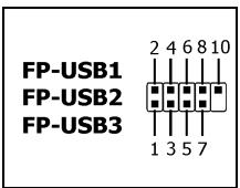
| Pin | Pin Assignment | Pin | Pin Assignment |
| 1 | VCC | 2 | VCC |
| 3 | Data0 - | 4 | Data1 - |
| 5 | Data0 + | 6 | Data1 + |
| 7 | Ground | 8 | Ground |
| 10 | NC |
※ Make sure the connecting cable bears the same pin assignment.
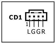
1.8.4 Internal Audio Connector
This connector connects to the audio output of internal CD-ROM drive or add-on card.
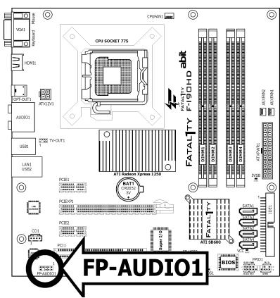
1.8.5 Front Panel Audio Connection Header
This header provides the front panel connection for HD (High Definition) Audio, yet for AC'97 Audio CODEC connection, you must carefully check the pin assignment before connecting from the front panel module. An incorrect connection may cause malfunction or even damage the motherboard.
Please do not connect the "Ground" cable or "USB VCC" cable from the front panel module to the Pin 4 "AVCC" of this header.
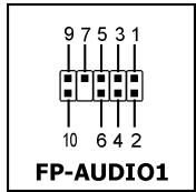
| Pin | Pin Assignment (HD AUDIO) |
| 1 | MIC2 L |
| 2 | AGND |
| 3 | MIC2 R |
| 4 | AVCC |
| 5 | FRO-R |
| 6 | MIC2_JD |
| 7 | F_IO_SEN |
| 9 | FRO-L |
| 10 | LINE2_JD |
| Pin | Pin Assignment (AC'97 AUDIO) |
| 1 | MIC In |
| 2 | GND |
| 3 | MIC Power |
| 4 | NC |
| 5 | Line Out (R) |
| 6 | NC |
| 7 | NC |
| 9 | Line Out (L) |
| 10 | NC |
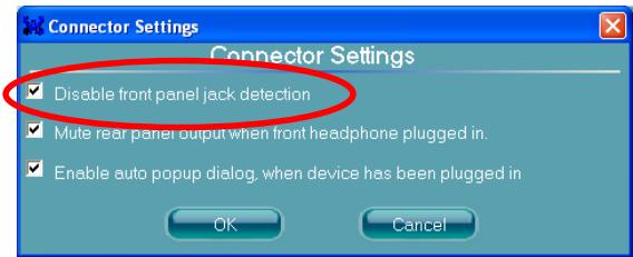
Driver Configuration for AC'97 audio connection:
The audio driver is originally configured to support HD Audio. For AC'97 audio connection, you may:
- Right-click the "Realtek HD Audio Manager" icon in system tray.

- Click "Audio I/O" tab, and then click "Connector Settings".
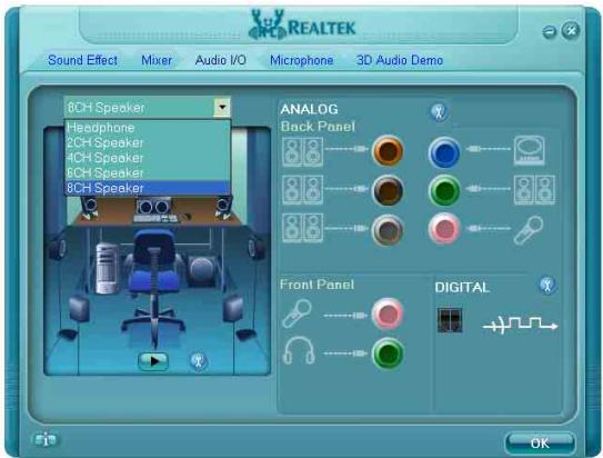
- Click "Disabled front panel jack detection", and then click "OK" to confirm.
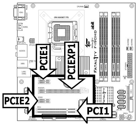
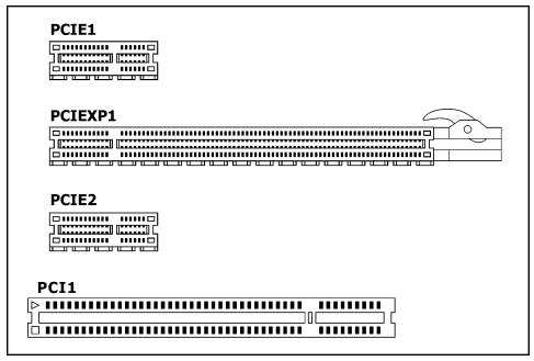
1.8.6 PCI and PCI Express X16, X1 Slots
Install PCI Express X16 graphics card into slot "PCIEXP1".
Install PCI Express X1 card into slot "PCIE1" and/or "PCIE2".
Install PCI card into slot "PCI1".
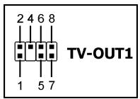
1.8.7 TV-OUT Header
This header is reserved for connecting an optional TV-Out card (Model name: HDTV-10).
1.9 Onboard Indicators and Buttons
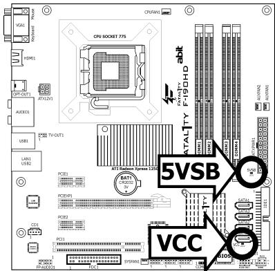
1.9.1 LED Indicators
5VSB: This LED lights up when the power supply is connected with power source.
VCC: This LED lights up when the system power is on.

1.10 Connecting Rear Panel I/O Devices
The rear I/O part of this motherboard provides the following I/O ports:
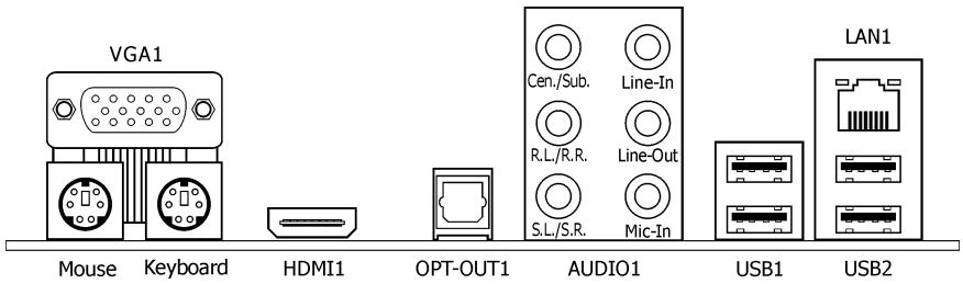
- Mouse: Connects to PS/2 mouse.
Keyboard: Connects to PS/2 keyboard.
VGA1: Connects to monitor input. - HDMI1: Connects to multimedia devices of HDMI protocol.
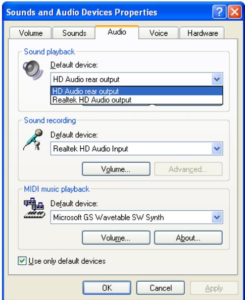
To enable this HDMI function, you will have to:
(1) Select the option [Normal] for the "HDMI Port Display" in BIOS Setup Menu "Advanced Chipset Features".
(2) Install the "Realtek Audio Driver (ATi HDMI)".
(3) Make sure to select "HD Audio rear output" as the sound playback device in the "Sounds and Audio Devices Properties" through Windows' Control Panel.
- OPT-OUT1: This connector provides an S/PDIF-Out connection through optical fiber to digital multimedia devices.
AUDIO1:
Cen./Sub. (Center / Subwoofer): Connects to the center and subwoofer channel in the 7.1-channel audio system.
R.L./R.R. (Rear Left / Rear Right): Connects to the rear left and rear right channel in the 7.1-channel audio system.
S.L./S.R. (Surround Left / Surround Right): Connects to the surround left and surround right channel in the 7.1-channel audio system.
Line-In: Connects to the line out from external audio sources.
Line-Out: Connects to the front left and front right channel in the 7.1-channel or regular 2-channel audio system.
Mic-In: Connects to the plug from external microphone.
LAN1: Connects to Local Area Network.
- USB1/USB2: Connects to USB devices such as scanner, digital speakers, monitor, mouse, keyboard, hub, digital camera, joystick etc.
2. BIOS Setup
This motherboard provides a programmable EEPROM so that you can update the BIOS utility. The BIOS (Basic Input/Output System) is a program that deals with the basic level of communication between processor and peripherals. Use the BIOS Setup program only when installing motherboard, reconfiguring system, or prompted to "Run Setup". This chapter explains the Setup Utility of BIOS utility.
After powering up the system, the BIOS message appears on the screen, the memory count begins, and then the following message appears on the screen:
PRESS DEL TO ENTER SETUP
If this message disappears before you respond, restart the system by pressing <Ctrl> + <Alt> + <Del> keys, or by pressing the Reset button on the computer chassis. Only when these two methods fail should you restart the system by powering it off and then back on.
After pressing <Del> key, the main menu screen appears.
| Phoenix - AwardBIOS CMOS Setup Utility | |
| ► SoftMenu Setup► Standard CMOS Features► Advanced BIOS Features► Advanced Chipset Features► Integrated Peripherals► Power Management Setup► PnP/PCI Configurations | ► PC Health StatusLoad Fail-Safe DefaultsLoad Optimized DefaultsSet PasswordSave & Exit SetupExit Without Saving |
| Esc: Quit↑↓→← : Select ItemF10: Save & Exit Setup (RS600-W627DHG-6A667A1AC-00) | |
| Change CPU's Clock & Voltage | |

In order to increase system stability and performance, our engineering staff is constantly improving the BIOS menu. The BIOS setup screens and descriptions illustrated in this manual are for your reference only, and may not completely match with what you see on your screen.
2.1 SoftMenu Setup
This option configures the CPU's clock and voltage.
| Phoenix - AwardBIOS CMOS Setup Utility SoftMenu Setup | |
| Brand Name: Genuine Intel(R) CPU 2.80GHz Frequency: 2.80GHz | Item Help |
| CPU Operating Speed 2800 (200) x - External Clock 200MHz x - Multiplier Factor 14 X x - Estimated New CPU Clock 2.80GHz x - DRAM Spec. (CPU:DRAM) By SPD | |
| Voltages Control Default x - CPU Core Voltage 1.300V x - DDR2 Voltage 1.80V x - NB 1.8 Voltage 1.800V | |
| ↑↓→←:Move Enter:Select +/-/PU/PD:Value F10:Save ESC:Exit F1:General Help F5: Previous Values F6: Fail-Safe Defaults F7: Optimized Defaults | |
Brand Name
This item displays the CPU model name installed on this motherboard.
Frequency
This item displays the processor speed of the CPU installed on this motherboard.
CPU Operating Speed
This item displays the CPU operating speed according to the type and speed of your CPU. Select the [User Defined] mode to enter the manual option.
Manual Option:
The wrong settings of the multiplier and external clock in certain circumstances may cause CPU damage. Setting the working frequency higher than the PCI chipset or processor specs, may cause abnormal memory module functioning, system hangs, hard disk drive data lose, abnormal functioning of the VGA card, or abnormal functioning with other add-on cards. Using non-specification settings for your CPU is not the intention of this explanation. These should be used for engineering testing, not for normal applications.
※ There will be no guaranty for the settings beyond specification. Any damage of any component on this motherboard or peripherals resulting therein is not our responsibility.
External Clock
This item selects the front side bus frequency.
Due to the specification limit of the CPU you installed, the speed you set over its standard bus speed is supported, but not guaranteed.
Multiplier Factor
This item displays the multiplier factor for the CPU you installed.
- Estimated New CPU Clock
This item displays an estimated CPU processor speed.
DRAM Spec. (CPU:DRAM)
This item determines the DRAM frequency.
Voltages Control
This option allows you to switch between the default and user-defined voltages. Leave this setting at default unless the current voltage setting cannot be detected or is not correct. The option "User Define" enables you to select the following voltages manually.
CPU Core Voltage
DDR2 Voltage
NB 1.8 Voltage
2.2 Standard CMOS Features
| Phoenix - AwardBIOS CMOS Setup Utility Standard CMOS Features | ||
| Date (mm:dd:yy) | Mon. Apr 23 2007 | Item Help |
| Time (hh:mm:ss) | 12 : 34 : 56 | |
| IDE Channel 1 Master | None | |
| IDE Channel 1 Slave | None | |
| SATA Channel 1 | None | |
| SATA Channel 2 | None | |
| SATA Channel 3 | None | |
| SATA Channel 4 | None | |
| Drive A | 1.44M, 3.5 in. | |
| Floppy 3 Mode Support | Disabled | |
| Halt On | All, But Keyboard | |
| Base Memory | 640K | |
| Extended Memory | 1047552K | |
| Total Memory | 1047552K | |
| ↑↓→←:Move Enter:Select +/-/PU/PD:Value F10:Save ESC:Exit F1:General Help F5: Previous Values F6: Fail-Safe Defaults F7: Optimized Defaults | ||
Date (mm:dd:yy)
This item sets the date you specify (usually the current date) in the format of [Month], [Date], and [Year].
Time (hh:mm:ss)
This item sets the time you specify (usually the current time) in the format of [Hour], [Minute], and [Second].
Click
| Phoenix - AwardBIOS CMOS Setup Utility IDE Channel 1 Master | ||
| IDE HDD Auto-Detection | Press Enter | Item Help |
| IDE Channel 1 Master | Auto | |
| Access Mode | Auto | |
| Capacity | 0 MB | |
| Cylinder | 0 | |
| Head | 0 | |
| Precomp | 0 | |
| Landing Zone | 0 | |
| Sector | 0 | |
| ↑↓→←:Move Enter:Select +/-/PU/PD:Value F10:Save ESC:Exit F1:General Help F5:Previous Values F6:Fail-Safe Defaults F7:Optimized Defaults | ||
IDE HDD Auto-Detection
This item allows you to detect the parameters of IDE or SATA drives by pressing
IDE Channel 1 Master/Slave, SATA Channel 1~4
When set to [Auto], the BIOS will automatically check what kind of IDE or SATA hard drive you are using. If you want to define your own drive yourself, set it to [Manual] and make sure you fully understand the meaning of the parameters. Please refer to the instruction manual provided by the device's manufacturer to get the setting right.
Access Mode
This item selects the mode to access your IDE or SATA devices. Leave this item at its default [Auto] setting to detect the access mode of your HDD automatically.
Capacity
This item displays the approximate capacity of the disk drive. Usually the size is slightly greater than the size of a formatted disk given by a disk-checking program.
Cylinder
This item configures the numbers of cylinders.
Head
This item configures the numbers of read/write heads.
Precomp
This item displays the number of cylinders at which to change the write timing.
Landing Zone
This item displays the number of cylinders specified as the landing zone for the read/write heads.
Sector
This item configures the numbers of sectors per track.

Back to Standard CMOS Features Setup Menu
Drive A
This item sets the type of floppy drives installed.
Floppy 3 Mode Support
This item allows you to use "3 Mode Floppy Drive" in Japanese computer systems. Leave this item at its default [Disabled] setting if you are not using this Japanese standard floppy drive.
Halt On
This item determines whether the system stops if an error is detected during system boot-up.
[All Errors]: The system-boot will stop whenever the BIOS detect a non-fatal error.
[No Errors]: The system-boot will not stop for any error detected.
[All, But Keyboard]: The system-boot will stop for all errors except a keyboard error.
[All, But Diskette]: The system-boot will stop for all errors except a diskette error.
[All, But Disk/Key]: The system-boot will stop for all errors except a diskette or keyboard error.
Base Memory
This item displays the amount of base memory installed in the system. The value of the base memory is typically 640K for systems with 640K or more memory size installed on the motherboard.
Extended Memory
This item displays the amount of extended memory detected during system boot-up.
Total Memory
This item displays the total memory available in the system.
2.3 Advanced BIOS Features
| Phoenix - AwardBIOS CMOS Setup Utility Advanced BIOS Features | ||
| Hyper-Threading Technology | Enabled | Item Help |
| Quick Power On Self Test | Enabled | |
| CPU Feature | Press Enter | |
| Hard Disk Boot Priority | Press Enter | |
| First Boot Device | Floppy | |
| Second Boot Device | Hard Disk | |
| Third Boot Device | IDE CDROM | |
| Boot Other Device | Enabled | |
| Boot Up Floppy Seek | Disabled | |
| Boot Up NumLock Status | On | |
| Security Option | Setup | |
| MPS Version Ctrl For OS | 1.4 | |
| Delay IDE Initial (Secs) | 0 | |
| Full Screen LOGO Show | Enabled | |
| Disable Unused PCI Clock | Yes | |
| ↑↓→←:Move Enter:Select +/-/PU/PD:Value F10:Save ESC:Exit F1:General Help F5: Previous Values F6: Fail-Safe Defaults F7: Optimized Defaults | ||
Hyper-Threading Technology
This item is used to enable the functionality of the processor with Hyper-Threading Technology and will appear only when using such processor.
The Hyper-Threading Technology helps your PC work more efficiently by maximizing processor resources and enabling a single processor to run two separate threads of software simultaneously, bringing forth greater performance and system responsiveness when running multiple applications at once.
Quick Power On Self Test
When set to [Enabled], this item speeds up the Power On Self Test (POST) after powering on the system. The BIOS shorten or skip some check during the POST.

CPU Feature
Click
| Phoenix - AwardBIOS CMOS Setup Utility CPU Feature | ||
| Thermal Control | Enabled | Item Help |
| Limit CPUID MaxVal | Disabled | |
| C1E Function | Enabled | |
| Execute Disable Bit | Enabled | |
| Virtualization Technology | Enabled | |
| EIST Function | Enabled | |
| ↑↓→←:Move Enter:Select +/-/PU/PD:Value F10:Save ESC:Exit F1:General Help F5:Previous Values F6:Fail-Safe Defaults F7:Optimized Defaults | ||
| Thermal Control This option enables or disables the thermal monitoring. | ||
| Limit CPUID MaxVal When set to [Enabled], this item limits the CPUID maximum value to 3, which is usually required for older OS like Windows NT4.0. Leave this item at its default [Disabled] settings for OS like Windows XP. | ||
| C1E Function This item appears only for certain processors with the C1E (Enhanced Halt State) Function. When set to [Enabled], the processor will further reduce the total power consumption. | ||
| Execute Disable Bit This item appears only for certain processors with the Execute Disable Bit (XD bit) feature. When set to [Enabled], this item allows the processor to prevent data pages from being used by malicious software to execute code and provide memory protection. | ||
| Virtualization Technology This option enables or disables the additional hardware capabilities provided by Virtualization Technology. | ||
| EIST Function This item appears only for certain processors with the EIST (Enhanced Intel SpeedStep Technology) Function. When set to [Enabled], EIST will dynamically switch between multiple frequency and voltage points to optimize the power and performance balance of the processor and system based on demand. Back to Advanced BIOS Features Setup Menu | ||
| Hard Disk Boot Priority This item selects the hard disks booting priority. By pressing <Enter> key, you can enter its submenu where the hard disks detected can be selected for the booting sequence to boot up system. This item functions only when there is the option of [Hard Disk] in any one of the First/Second/Third Boot Device items. | ||
| First Boot Device / Second Boot Device / Third Boot Device / Boot Other Device Select the drive to boot first, second and third in the [First Boot Device], [Second Boot Device], and [Third Boot Device] items respectively. The BIOS will boot the operating system according to the sequence of the drive selected. Set [Boot Other Device] to [Enabled] if you wish to boot from another device other than these three items. | ||
| Boot Up Floppy Seek When set to [Enabled], the BIOS will check whether the floppy disk drive is installed or not. | ||
| Boot Up NumLock Status This item determines the default state of the numeric keyboard at system booting up. [On]: The numeric keyboard functions as number keys. | ||
[Off]: The numeric keypad functions as arrow keys.
Security Option
This item determines when the system will prompt for password - every time the system boots or only when enters the BIOS setup.
[Setup]: The password is required only when accessing the BIOS Setup.
[System]: The password is required each time the computer boots up.
※ Don't forget your password. If you forget the password, you will have to open the computer case and clear all information in the CMOS before you can start up the system. But by doing this, you will have to reset all previously set options.
MPS Version Ctrl For OS
This item specifies which version of MPS (Multi-Processor Specification) this motherboard will use. Leave this item at its default setting.
Delay IDE Initial (Secs)
This item allows the BIOS to support some old or special IDE devices by prolonging this delay time. A larger value will give more delay time to the device for which to initialize and to prepare for activation.
Full Screen LOGO Show
This item determines to show the full screen logo when booting.
Disable Unused PCI Clock
This option disables the clock of PCI slot that is not in use.
2.4 Advanced Chipset Features
| Phoenix - AwardBIOS CMOS Setup Utility Advanced Chipset Features | ||
| DRAM Timing Selectable | By SPD | Item Help |
| x - CAS Latency Time (tCL) | 5 | |
| x - RAS# to CAS# Delay (tRCD) | 5 | |
| x - RAS# Precharge (tRP) | 5 | |
| x - Precharge Delay (tRAS) | 15 | |
| x - Refresh Cycle Time (tRFC) | 20 | |
| GFX Link Width | x16 | |
| Surround View Function | Disabled | |
| Init Display First | PCI Slot | |
| UMA Frame Buffer Size | 64MB | |
| HDMI Port Display | DVI | |
| ↑↓→←:Move Enter:Select +/-/PU/PD:Value F10:Save ESC:Exit F1:General Help F5: Previous Values F6: Fail-Safe Defaults F7: Optimized Defaults | ||
DRAM Timing Selectable
This item sets the optimal timings for the following four items, depending on the memory module you are using. The default setting "By SPD" configures these four items by reading the contents in the SPD (Serial Presence Detect) device. The EEPROM on the memory module stores critical parameter information about the module, such as memory type, size, speed, voltage interface, and module banks. The following items will be available to make adjustments by selecting option [Manual].
CAS Latency Time (tCL)
RAS# to CAS# Delay (tRCD)
RAS# Precharge (tRP)
Precharge Delay (tRAS)
Refresh Cycle Time (tRFC)
GFX Link Width
This item specifies the bandwidth for slot [PCIEXP1].
Surround View Function
This item allows you to enable or disable the surround view function.
This item appears only when the slot [PCIEXP1] has been installed with an ATI graphics card.
Init Display First
This item allows you to choose the primary display card.
UMA Frame Buffer Size
This item selects the size of memory pre-allocated for frame buffer.
In the applications that require higher frame buffer size, such as 3-D game, HDMI, or Blu-ray DVD playing, please select the option [256MB] for higher video performance.
HDMI Port Display
This item selects the type of display device connected through the "HDMI Port" on this motherboard.
[DVI]: Select this option if you are connecting a non-HDMI monitor through the "HDMI Port" on this motherboard. This is the default setting.
[Normal]: Select this option if you are connecting HDMI digital display through the "HDMI Port" on this motherboard.
An unmatched configuration will cause the display device abnormal. For example, an HDMI digital device connected to "HDMI Port" under the [DVI] selection will have no sound on the digital display, whereas a non-HDMI monitor connected to "HDMI Port" under the [Normal] selection will cause the screen flickering. Select the correct one for your display device.
2.5 Integrated Peripherals
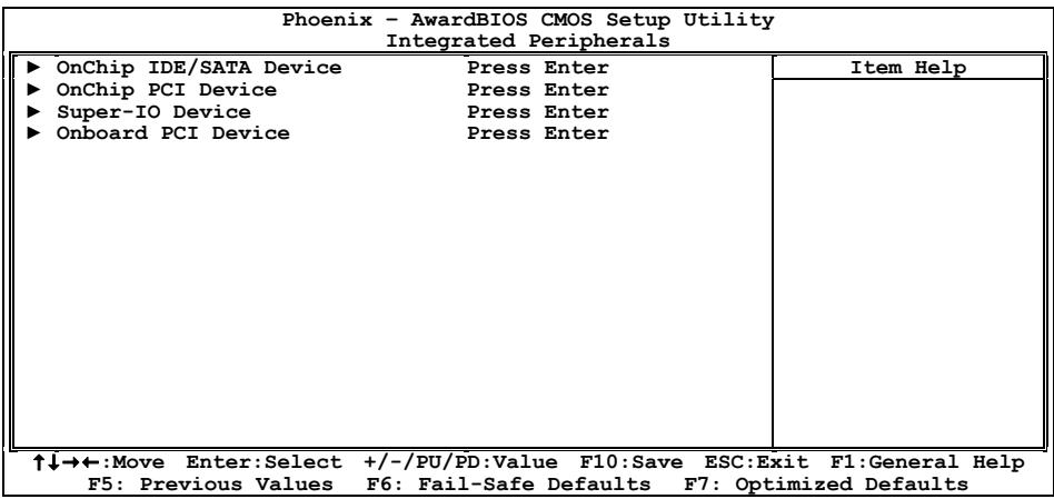

OnChip IDE/SATA Device
Click
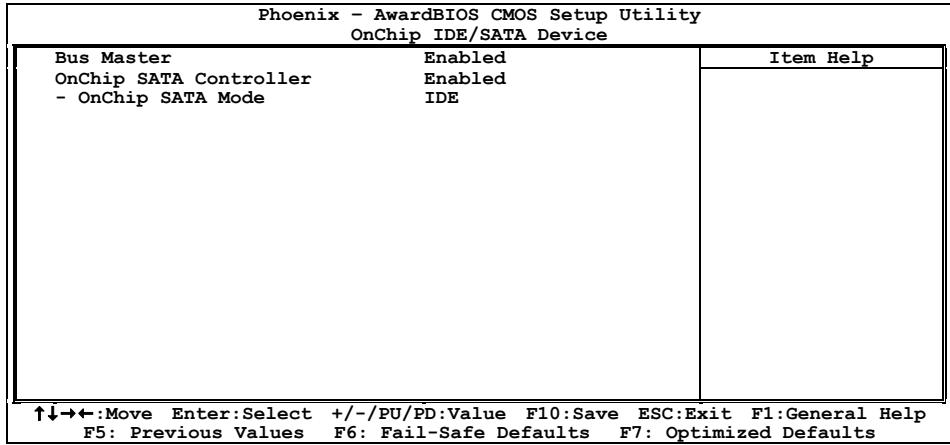
Bus Master
This option enables or disables the IDE bus mastering capability under the DOS environment.
OnChip SATA Controller
This option enables or disables the onchip SATA controller.
OnChip SATA Mode
This item selects the mode for devices connected through SATA ports.

OnChip PCI Device
Click
| Phoenix - AwardBIOS CMOS Setup Utility OnChip PCI Device | ||
| OnChip USB Controller | Enabled | Item Help |
| - USB 2.0 Controller | Enabled | |
| - USB Keyboard Support via | OS | |
| - USB Mouse Support via | OS | |
| OnChip Audio Controller | Enabled | |
| ↑↓→←:Move Enter:Select +/-/PU/PD:Value F10:Save ESC:Exit F1:General Help F5: Previous Values F6: Fail-Safe Defaults F7: Optimized Defaults | ||
OnChip USB Controller
This option enables or disables the USB controller.
USB 2.0 Controller
This option enables or disables the USB 2.0 controller.
USB Keyboard Support via
Select [BIOS] for the legacy operating system (such as DOS) that does not support USB keyboard.
USB Mouse Support via
Select [BIOS] for the legacy operating system (such as DOS) that does not support USB mouse.
OnChip Audio Controller
This option enables or disables the audio controller.
Click
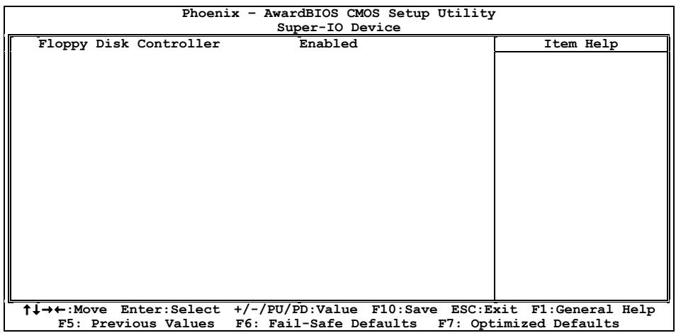
Floppy Disk Controller
This option enables or disables the floppy disk controller.

Onboard PCI Device
Click
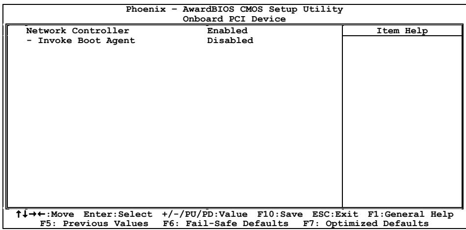
Network Controller
This option enables or disables the LAN controller.
- Invoke Boot Agent
This item allows you to use the boot ROM (instead of a disk drive) to boot up the system and access the local area network directly.
2.6 Power Management Setup
| Phoenix - AwardBIOS CMOS Setup Utility Power Management Setup | ||
| ACPI Suspend Type | S3(Suspend To RAM) | Item Help |
| - Resume by USB From S3 | Enabled | |
| Power Button Function | Instant-Off | |
| Wake Up by PME# of PCI | Disabled | |
| Wake Up by Onboard LAN | Disabled | |
| Wake Up by Wake# of PCIe | Disabled | |
| Wake Up by Alarm | Disabled | |
| X - Date(of Month) Alarm | 0 | |
| X - Time(hh:mm:ss) Alarm | 0 : 0 : 0 | |
| Power On Function | Button Only | |
| X - KB Power On Password | Enter | |
| X - Hot Key Power On | Ctrl-F1 | |
| Restore On AC Power Loss | Power Off | |
| ↑↓→←:Move Enter:Select +/-/PU/PD:Value F10:Save ESC:Exit F1:General Help F5: Previous Values F6: Fail-Safe Defaults F7: Optimized Defaults | ||
ACPI Suspend Type
This item selects the type of Suspend mode.
Resume by USB From S3
When set to [Enabled], this item allows you to use a USB device to wake up a system that is in the S3 (STR - Suspend To RAM) state. This item can be configured only if the item "ACPI Suspend Type" is set to [S3(STR)].
Power Button Function
This item selects the method of powering off your system:
[Delay 4 Sec.]: Pushing the power button for more than 4 seconds will power off the system. This will prevent the system from powering off in case you accidentally hit or pushed the power button.
[Instant-Off]: Pressing and then releasing the power button at once will immediately power off the system.
Wake Up by PME# of PCI
When set to [Enabled], access through the add-on PCI card can remotely wake up the system that was in Soft-Off condition. The PCI card must support the wake up function.
Wake Up by Onboard LAN
When set to [Enabled], access through the onboard LAN port can remotely wake up the system that was in Soft-Off condition.
Wake Up by Wake# of PCIe
When set to [Enabled], access through the add-on PCI Express card can remotely wake up the system that was in Soft-Off condition. The PCI Express card must support the wake up function.
Wake Up by Alarm
When set to [Enabled], you can set the date and time you would like the Soft-Off PC to power-on in the "Date (of Month) Alarm" and "Time (hh:mm:ss) Alarm" items. However, if the system is being accessed by incoming calls or the network (Resume On Ring/LAN) prior to the date and time set in these items, the system will give priority to the incoming calls or network instead.
- Date (of Month) Alarm
[0]: This option power-on the system everyday according to the time set in the "Time (hh:mm:ss) Alarm" item.
[1-31]: This option selects a date you would like the system to power-on. The system will power-on on the date set, and the time set in the "Time (hh:mm:ss) Alarm" item.
Time (hh:mm:ss) Alarm
This item sets the time you would like the system to power-on.
Power On Function
This item selects the way you want your system to power on.
[Password]: Use a password to power on the system, select this option then press
[Hot KEY]: Use any of the function keys between <F1> to <F12> to power on the system.
[Mouse Left]: Double click the mouse left button to power on the system.
[Mouse Right]: Double click the mouse right button to power on the system.
[Any KEY]: Use any keyboard keys to power on the system.
[Button Only]: Use only the power button to power on the system.
[Keyboard 98]: Use the power-on button on the "Keyboard 98" compatible keyboard to power on the system.
The mouse wake up function can only be used with the PS/2 mouse, not with the COM port or USB type. Some PS/2 mice cannot wake up the system because of compatible problems. If the specs of your keyboard are too old, it may fail to power on.
KB Power On Password
This item sets the password required in order to power on your computer.
Do not forget your password, or you will have to clear the CMOS and reset all parameters in order to utilize this function again.
Hot Key Power On
This item powers on the system by pressing
Restore On AC Power Loss
This item selects the system action after an AC power failure.
[Power Off]: When power returns after an AC power failure, the system's power remains off. You must press the Power button to power-on the system.
[Power On]: When power returns after an AC power failure, the system's power will be powered on automatically.
[Last State]: When power returns after an AC power failure, the system will return to the state where you left off before power failure occurred. If the system's power is off when AC power failure occurs, it will remain off when power returns. If the system's power is on when AC power failure occurs, the system will power-on when power returns.
2.7 PnP/PCI Configurations
| Phoenix - AwardBIOS CMOS Setup Utility PnP/PCI Configurations | ||
| Resources Controlled By x - IRQ Resources | Auto Press Enter | Item Help |
| PCI/VGA Pallete Snoop PCI Latency Timer(CLK) | Disbaled 64 | |
| ** PCI Express relative items ** Maximum Payload Size | 4096 | |
| ↑↓→←:Move Enter:Select +/-/PU/PD:Value F10:Save ESC:Exit F1:General Help F5: Previous Values F6: Fail-Safe Defaults F7: Optimized Defaults | ||
Resources Controlled By
This item configures all of the boot and Plug-and-Play compatible devices.
[Auto]: The system will automatically detect the settings.
[Manual]: Choose the specific IRQ resources in the "IRQ Resources" menu.
- IRQ Resources
Click
This item sets each system interrupt to either [PCI Device] or [Reserved].
| Phoenix - AwardBIOS CMOS Setup Utility - IRQ Resources | ||
| IRQ-3 assigned to | Reserved | Item Help |
| IRQ-4 assigned to | PCI Device | |
| IRQ-5 assigned to | PCI Device | |
| IRQ-7 assigned to | PCI Device | |
| IRQ-10 assigned to | PCI Device | |
| IRQ-11 assigned to | PCI Device | |
| ↑↓→←:Move Enter:Select +/-/PU/PD:Value F10:Save ESC:Exit F1:General Help F5:Previous Values F6:Fail-Safe Defaults F7:Optimized Defaults | ||
PCI/VGA Palette Snoop
This item determines whether the MPEG ISA/VESA VGA cards can work with PCI/VGA or not.
[Enabled]: MPEG ISA/VESA VGA cards work with PCI/VGA.
[Disabled]: MPEG ISA/VESA VGA cards do not work with PCI/VGA.
PCI Latency Timer (CLK)
This item controls how long each PCI device can hold the bus before another takes over. When set to higher values, every PCI device can conduct transactions for a longer time and thus improve the effective PCI bandwidth. For better PCI performance, you should set the item to higher values.
Maximum Payload Size
This item sets the maximum TLP payload size for the PCI Express devices.
2.8 PC Health Status
| Phoenix - AwardBIOS CMOS Setup Utility PC Health Status | ||
| ▲ ABIT FanEQ Control | Press Enter | Item Help |
| FAN Fail Alarm Selectable | Disabled | |
| Shutdown When FAN Fail | CPU FAN | |
| CPU Shutdown Temperature | 90°C/ 194°F | |
| CPU Warning Temperature | 80°C/ 176°F | |
| CPU Temperature | 35°C/ 95°F | |
| System Temperature | 32°C/ 89°F | |
| PWM Temperature | 35°C/ 95°F | |
| CPU FAN Speed | 3245 RPM | |
| SYS FAN Speed | 4218 RPM | |
| AUX1 FAN Speed | 0 RPM | |
| AUX2 FAN Speed | 0 RPM | |
| CPU Core Voltage | 1.25V | |
| DDR2 Voltage | 1.80V | |
| DDR2 VTT Voltage | 0.88V | |
| PCIe Voltage | 1.20V | |
| ATX +12V | 12.00V | |
| ATX +3.3V | 3.29V | |
| ↑↓→←:Move Enter:Select +/-/PU/PD:Value F10:Save ESC:Exit F1:General Help F5: Previous Values F6: Fail-Safe Defaults F7: Optimized Defaults | ||

ABIT FanEQ Control
This item determines the temperature threshold to raise the fan attached at CPU and SYS fan headers up to their full speed.
Click
| Phoenix - AwardBIOS CMOS Setup Utility ABIT FanEQ Control | ||
| CPU FanEQ control | Enabled | Item Help |
| - FanEQ Target Temp. | 50°C/122°F | |
| - FanEQ Temp. Tolerance | 5°C/ 41°F | |
| - FanEQ Start Control | 80% | |
| - FanEQ Stop Control | 50% | |
| SYS FanEQ Control | Enabled | |
| - FanEQ Target Temp. | 35°C/ 95°F | |
| - FanEQ Temp. Tolerance | 5°C/ 41°F | |
| - FanEQ Start Control | 70% | |
| - FanEQ Stop Control | 50% | |
| ↑↓→←:Move Enter:Select +/-/PU/PD:Value F10:Save ESC:Exit F1:General Help F5: Previous Values F6: Fail-Safe Defaults F7: Optimized Defaults | ||
CPU FanEQ Control
This item allows you to control the CPUFAN speed. When set to [Enabled], the following items become configurable.
FanEQ Target Temp.
This item sets the temperature mark for the "CPU FanEQ" function to take effect.
FanEQ Temp. Tolerance
This item sets the temperature tolerance range for the item "FanEQ Target Temp."
FanEQ Start Control
This item sets the speed ratio for the CPU fan assembly connected at "CPUFAN1" fan power connector to start running.
FanEQ Stop Control
This item sets the lowest speed ratio for the CPU fan assembly connected at "CPUFAN1" fan power connector to run at when the CPU temperature detected is lower than the value of item "FanEQ Target Temp." plus the value of item "FanEQ Temp. Tolerance".
In the situation when the CPU temperature detected is higher than the value of item "FanEQ Target Temp." plus the value of item "FanEQ Temp. Tolerance", the speed ratio for the CPU fan assembly connected at "CPUFAN1" fan power connector will first run at the speed ratio set by the item "FanEQ Start Control", and then up to 100% .
SYS FanEQ Control
This item allows you to control the SYSFAN speed. When set to [Enabled], the following items become configurable.
FanEQ Target Temp.
This item sets the temperature mark for the "SYS FanEQ" function to take effect.
FanEQ Temp. Tolerance
This item sets the temperature tolerance range for the item "FanEQ Target Temp."
FanEQ Start Control
This item sets the speed ratio for the fan assembly connected at "SYSFAN1" fan power connector to start running.
FanEQ Stop Control
This item sets the lowest speed ratio for the fan assembly connected at "SYSFAN1" fan power connector to run at when the temperature of "FanEQ Reference Temp." detected is lower than the value of item "FanEQ Target Temp." plus the value of item "FanEQ Temp. Tolerance".
In the situation when the temperature of "FanEQ Reference Temp." detected is higher than the value of item "FanEQ Target Temp." plus the value of item "FanEQ Temp. Tolerance", the speed ratio for the fan assembly connected at "SYSFAN1" fan power connector will first run at the speed ratio set by the item "FanEQ Start Control", and then up to 100% .

Back to PC Health Status Setup Menu
FAN Fail Alarm Selectable
This item selects the fan that will be monitored for malfunction.
| Shutdown When FAN Fail When set to [Enabled], the system will be shut down if the CPU fan is not running. |
| CPU Shutdown Temperature This item sets the temperature that will shutdown the system automatically in order to prevent system overheats. |
| CPU Warning Temperature This item selects the CPU's warning temperature limit. Once the system has detected that the CPU's temperature exceeded the limit, warning beeps will sound. |
| All Voltages, Fans Speed and Thermal Monitoring These unchangeable items list the current status of the CPU and environment temperatures, fan speeds, and system power voltage. |
| 2.9 Load Fail-Safe Defaults This option loads the BIOS default values for the most stable, minimal-performance system operations. |
| 2.10 Load Optimized Defaults This option loads the BIOS default values that are factory settings for optimal-performance system operations. |
| 2.11 Set Password This option protects the BIOS configuration or restricts access to the computer itself. |
| 2.12 Save & Exit Setup This option saves your selections and exits the BIOS setup menu. |
| 2.13 Exit Without Saving This option exits the BIOS setup menu without saving any changes. |
| For more information: WWW.ABIT.COM.TW WWW.FATALITY.COM |
3. Driver & Utility
The "Driver- & - Utility CD" that came packed with this motherboard contains drivers, utilities and software applications required for its basic and advanced features.
3.1 CD-ROM AUTORUN
To run the CD-ROM automatically:
-
Place the "Driver-&-Utility CD" into the CD-ROM drive in your system. The following installation auto-run screen appears. If not, browse the root directory of the CD-ROM via the File Manager, and double click the "AUTORUN" file.
-
Click the item needed for installation.
-
[Drivers]: Click to enter the driver installation menu.
- [Manual]: Click to enter the user's manual menu.
- [Utility]: Click to enter the utilities installation menu.
-
[abit Utility]: Click to enter the installation menu of utilities exclusively developed by abit.
-
[Browse CD] : Click to browse the contents of this "Driver-&-Utility CD".
-
[Close] Click to exit this installation menu.
-
The Windows will automatically search for current and updated software by looking up your computer.
When this "Found New Hardware Wizard" window appears. Click [Cancel] to start the following procedures.

Found New Hardware Wizard
Welcome to the Found New Hardware Wizard
Windows will search for current and updated software by looking on your computer, on the hardware installation CD, or on the Windows Update Web site (with your permission). Read our privacy policy
Can Windows connect to Windows Update to search for software?
Yes, this time only
Yes, now and every time I connect a device
No, not this time.
Click Next to continue.
<Back
Next>
Cancel
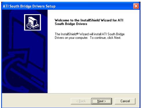
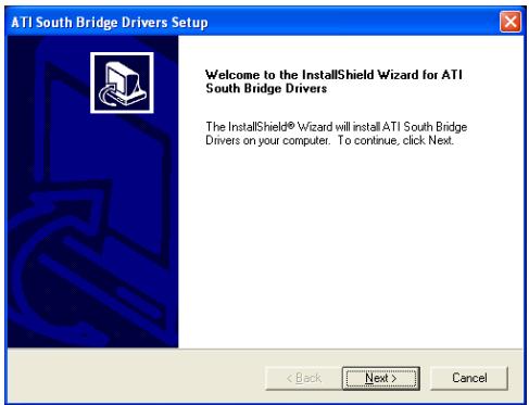
3.2 ATi South Bridge Driver
This program enables the chipset function.
※ Please install this driver first after having installed the Windows operating system.
To install this program:
- Click on the [Drivers] tab in the installation menu screen.
- Click the [ATi South Bridge Driver] item. The installation screen appears.
- Follow the prompts on the screen to complete installation.
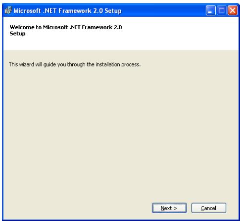
3.3 Microsoft.NET Framework
This program enables the amendment for ATi Catalyst.
※ Please install this driver first before installing the ATI VGA driver.
To install this program:
- Click on the [Drivers] tab in the installation menu screen.
- Click the [Microsoft.NET Framework] item. The installation screen appears.
- Follow the prompts on the screen to complete installation.
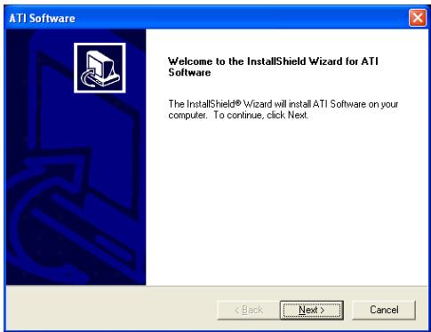
3.4 ATi VGA Driver
This program enables the [VGA1] connector function.
To install this program:
- Click on the [Drivers] tab in the installation menu screen.
- Click the [ATi VGA Driver] item. The installation screen appears.
- Follow the prompts on the screen to complete installation.
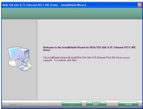
3.5 Realtek LAN Driver
This program enables the [LAN1] connector function.
To install this program:
- Click on the [Drivers] tab in the installation menu screen.
- Click the [Realtek LAN Driver] item. The installation screen appears.
- Follow the prompts on the screen to complete installation.
3.6 Realtek Audio Driver (ATi HDMI)
This program is capable of enabling function for both [AUDIO1] and [HDMI] connectors located at rear I/O panel.
Before installing the ATI HDMI driver together with the Realtek audio driver, you will have to select the option [Normal] for the "HDMI Port Display" in BIOS Setup Menu "Advanced Chipset Features".
To install this program:
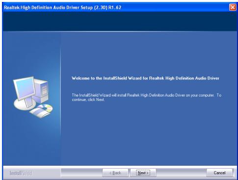
- Click on the [Drivers] tab in the installation menu screen.
- Click the [Realtek Audio Driver (Ati HDMI)] item. The installation screen appears.
-
Follow the prompts on the screen to complete installation.
-
After restarting the system, right-click the Sound Manager icon located at the desktop shortcut. Click item "Sound Manager". The Realtek HD Audio Manager appears.

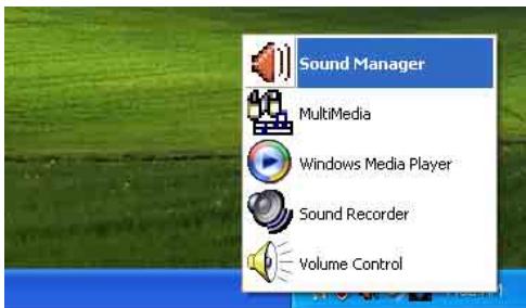
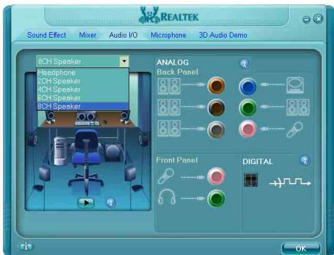
- Click the [Audio I/O] tab.
- Click the pull down menu to select the channel configuration.
- Click [OK] button to apply the Audio I/O settings and exit.
To enable the audio function through HDMI connector:
- Double-click the "Sounds and Audio Devices" icon through Windows' Control Panel to enter its properties.

- You may also get in the "Multimedia" menu directly by right-clicking your mouse button on the "Sound Manager" icon located at the desktop shortcut.
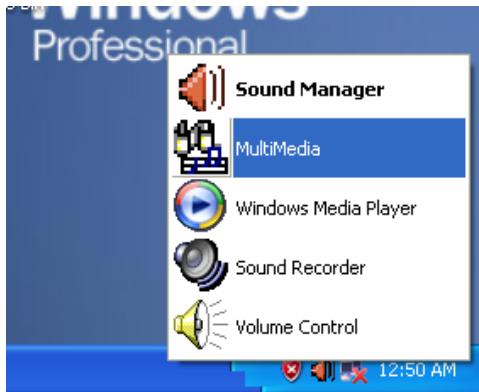
- To enable the audio function through HDMI connector, make sure to select "HD Audio rear output" as the sound playback device in this "Sounds and Audio Devices Properties". The audio function through "Realtek HD Audio output" will then be disabled consequently.
Click [OK] to exit.
If you leave the sound playback device at the "Realtek HD Audio output" for HDMI connection, the audio will come out through the "AUDIO1" connector at rear panel instead.
3.7 ATI RAID Driver
This program enables the RAID function for [SATA] connectors.
To install this program:
- Click on the [Drivers] tab in the installation menu screen.
- Click the [ATi RAID Driver] item. The installation screen appears.
- Follow the prompts on the screen to complete installation.
3.8 USB 2.0 Driver
There is no need to install this driver for Windows 2000 with Service Pack 4, Windows XP with Service Pack 1, or their later version.
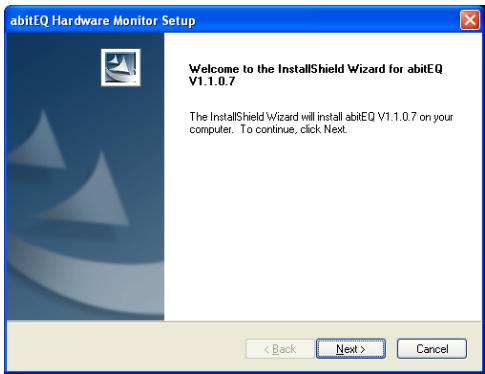
3.9 abit EQ
The [abit EQ] is a self-diagnostic system designed to protect PC Hardware by monitoring critical items of Power Supply Voltage, CPU & System Fans Speed, and CPU & System Temperature.
To install this utility:
- Click on the [abit Utility] tab in the installation menu screen.
- Click the [abit EQ] item. The following screen appears.

- Follow the prompts on the screen to complete installation.
- Restart the system for the program to take effect.
- Execute the [abit EQ] by entering the Windows Menu [Start] [All Programs] [abit] [abitEQ].
- The [abit EQ] shows you the status of Voltage, Fan Speed, and Temperature readings as well.

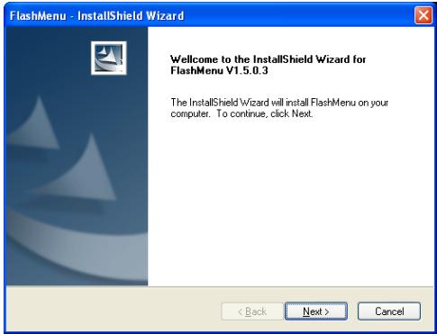
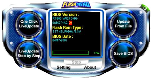
3.10 FlashMenu (BIOS Update Utility)
The [FlashMenu] is the most stable Windows-based BIOS flash available. No more worries about crashing. With one click of BIOS updating, users can flash their BIOS more easily and in less time.
To install this utility:
- Click on the [abit Utility] tab in the installation menu screen.
- Click the [FlashMenu] item. The following screen appears.

- Follow the prompts on the screen to complete installation.
- Restart the system for the program to take effect.
- Execute the FlashMenu by entering the Windows Menu [Start] [All Programs] [abit] [FlashMenu].
- This FlashMenu screen appears. You can easily update the BIOS from clicking [Update From File], [One Click LiveUpdate], or [LiveUpdate Step by Step] button.
3.11 SATA RAID Driver (for Windows Vista)
The Raid Driver needed when installing Windows Vista operating system is located at the following path of your CD-ROM drive after placing the "Driver- & Utility CD" into it:
For Vista 32bit CD-ROM Drive:\Drivers\SATARIAID\ATi\Vista32
For Vista 64bit CD-ROM Drive:\Drivers\SATARIAID\ATi\Vista64
3.12 SATA RAID Driver (for Windows XP, 2003, or 2000)
The "Driver Disk Maker" program bundled in the Driver-&-Utility CD is a utility to build the driver program needed for SATA controller into a floppy disk under DOS environment. This procedure is necessary only for installing Windows operating system to the hard disk connected to "SATA1 ~ SATA4" connector.
To create a driver disk:
- Before starting, connect a 3.5'' floppy disk drive to the "FDC1" connector, and connect a CD-ROM drive to your motherboard. Prepare a 3.5'' floppy disk.
- After completing all the start-up preparation for hardware setup, power on the system.
- Enter the BIOS Setup Menu by hitting <Del> key ^1 . Enter and select the BIOS menu "Advanced BIOS Features". Configure the option "First Boot Device" to "CD-ROM" drive. Save this selection and exit BIOS setup menu by accessing the BIOS menu "Save & Exit Setup".
- Restart the system. The system will now boot from CD, and enter the ABIT Boot Manager, the following options appear3:
(0) Boot From First HDD
(1) Make Driver Disk
(2) Boot From First Floppy Drive
(3) Skip CD-ROM Boot (Try Next Boot Device)
Type <1> and hit
(1) Make Driver Disk
(2) Exit
Type <1> and hit
- The driver options appear:
(1) ATi SATA RAID Driver Disk for WinXP_2K_2003
Type the number of the actions you want and hit
- Insert floppy disk to the floppy drive4. Press any key to continue.
- Copying files to floppy now starts. After completed copying, hit the <n> key if you do not want to make another Driver Disk, and stop at the A:> prompt.
- Take out the Driver- &- Utility CD from the CD-ROM drive now. Restart your system ^5 .