
PM11S3 - Integrated amplifier MARANTZ - Free user manual and instructions
Find the device manual for free PM11S3 MARANTZ in PDF.

| Product Type | Stereo Integrated Amplifier |
| Brand | Marantz |
| Model | PM11S3 |
| Output Power | 2 x 95 W (8 Ω), 2 x 140 W (4 Ω) |
| Load Impedance | 4 - 16 Ω |
| Frequency Response | 5 Hz - 100 kHz (±3 dB) |
| Total Harmonic Distortion | 0.01% (1 kHz, 8 Ω, 1 W) |
| Signal-to-Noise Ratio | 106 dB (Line Input) |
| Analog Inputs | 5 x RCA (Line), 1 x XLR (Balanced), 1 x Phono (MM/MC) |
| Outputs | 1 x RCA Pre-out, 1 x Headphone Output (6.35 mm) |
| Dimensions (W x H x D) | 440 x 123 x 444 mm |
| Weight | 14.5 kg |
| Power Supply | 230 V AC, 50/60 Hz |
| Power Consumption | 300 W (max), <0.3 W (Standby) |
| Special Features | HDAM Amplifier, High Current Circuit, Toroidal, Phono Input MM/MC |
| Chassis Material | Brushed Aluminum |
| Included Accessories | Power Cord, Remote Control, Batteries, User Manual |
| Maintenance and Cleaning | Dust with a soft, dry cloth. Do not use chemical products. |
| Safety | Ensure adequate ventilation, do not block openings, unplug when not in use for an extended period. |
| Spare Parts and Repairability | Contact an authorized Marantz service center for repairs. Repairability index not provided. |
Frequently Asked Questions - PM11S3 MARANTZ
User questions about PM11S3 MARANTZ
0 question about this device. Answer the ones you know or ask your own.
Ask a new question about this device
Download the instructions for your Integrated amplifier in PDF format for free! Find your manual PM11S3 - MARANTZ and take your electronic device back in hand. On this page are published all the documents necessary for the use of your device. PM11S3 by MARANTZ.
USER MANUAL PM11S3 MARANTZ
Model PM-11S3 Owner's Manual
Integrated Amplifier
SAFETY PRECAUTIONS

CAUTION
RISK OF ELECTRIC SHOCK DO NOT OPEN

CAUTION:
TO REDUCE THE RISK OF ELECTRIC SHOCK, DO NOT REMOVE COVER (OR BACK). NO USER-SERVICEABLE PARTS INSIDE. REFER SERVICING TO QUALIFIED SERVICE PERSONNEL.

The lightning flash with arrowhead symbol, within an equilateral triangle, is intended to alert the user to the presence of uninsulated "dangerous voltage" within the product's enclosure that may be of sufficient magnitude to constitute a risk of electric shock to persons.

The exclamation point within an equilateral triangle is intended to alert the user to the presence of important operating and maintenance (servicing) instructions in the literature accompanying the appliance.
WARNING:
TO REDUCE THE RISK OF FIRE OR ELECTRIC SHOCK, DO NOT EXPOSE THIS APPLIANCE TO RAIN OR MOISTURE.

Hot surface mark
CAUTION:
The top surface over the internal heat sink may become hot when operating this product continuously.
Do not touch hot areas, especially around the "Hot surface mark" and the top panel.
PRECAUTION:
SURFACE CHAUBE. NE PASTOUCHER.
- Read these instructions.
- Keep these instructions.
- Heed all warnings.
- Follow all instructions.
- Do not use this apparatus near water.
- Clean only with dry cloth.
- Do not block any ventilation openings. Install in accordance with the manufacturer's instructions.
- Do not install near any heat sources such as radiators, heat registers, stoves, or other apparatus (including amplifiers) that produce heat.
- Do not defeat the safety purpose of the polarized or grounding-type plug. A polarized plug has two blades with one wider than the other. A grounding type plug has two blades and a third grounding prong. The wide blade or the third prong are provided for your safety. If the provided plug does not fit into your outlet, consult an electrician for replacement of the obsolete outlet.
- Protect the power cord from being walked on or pinched particularly at plugs, convenience receptacles, and the point where they exit from the apparatus.
- Only use attachments/accessories specified by the manufacturer.
- Use only with the cart, stand, tripod, bracket, or table specified by the manufacturer, or sold with the apparatus. When a cart is used, use caution when moving the cart/ apparatus combination to avoid injury from tip-over.
- Unplug this apparatus during lightning storms or when unused for long periods of time.
- Refer all servicing to qualified service personnel. Servicing is required when the apparatus has been damaged in any way, such as power-supply cord or plug is damaged, liquid has been spilled or objects have fallen into the apparatus, the apparatus has been exposed to rain or moisture, does not operate normally, or has been dropped.
- Batteries shall not be exposed to excessive heat such as sunshine, fire or the like.
CAUTION:
To completely disconnect this product from the mains, disconnect the plug from the wall socket outlet.
The mains plug is used to completely interrupt the power supply to the unit and must be within easy access by the user.
PRECAUTION:
FCC INFORMATION (For US customers)
1.PRODUCT
This product complies with Part 15 of the FCC Rules. Operation is subject to the following two conditions: (1) this product may not cause harmful interference, and (2) this product must accept any interference received, including interference that may cause undesired operation.
2. IMPORTANT NOTICE: DO NOT MODIFY THIS PRODUCT
This product, when installed as indicated in the instructions contained in this manual, meets FCC requirements. Modification not expressly approved by Marantz may void your authority, granted by the FCC, to use the product.
3. NOTE
This product has been tested and found to comply with the limits for a Class B digital device, pursuant to Part 15 of the FCC Rules. These limits are designed to provide reasonable protection against harmful interference in a residential installation.
This product generates, uses and can radiate radio frequency energy and, if not installed and used in accordance with the instructions, may cause harmful interference to radio communications. However, there is no guarantee that interference will not occur in a particular installation. If this product does cause harmful interference to radio or television reception, which can be determined by turning the product OFF and ON, the user is encouraged to try to correct the interference by one or more of the following measures:
- Reorient or relocate the receiving antenna.
- Increase the separation between the equipment and receiver.
- Connect the product into an outlet on a circuit different from that to which the receiver is connected.
- Consult the local retailer authorized to distribute this type of product or an experienced radio/TV technician for help.
For Canadian customers:
This Class B digital apparatus complies with Canadian ICES-003.
Cautions on installation
Thank you for purchasing this marantz product. To ensure proper operation, please read this owner's manual carefully before using the product.
After reading the manual, be sure to keep it for future reference.
Contents
Getting started
Accessories 1
About this manual 1
Cautions on handling 2
About the remote control 2
Inserting the batteries 2
Operating range of the remote control unit 2
Features 3
Part names and functions 4
Front panel 4
Rear panel 4
Remote control 5
Basic connections 6
Preparations 6
Connecting cables 6
Connecting the audio equipment 6
Connecting the speakers 7
Connecting the speakers cables 7
Speaker connections 8
Bi-wiring connection 8
Connecting players 9
Connecting recorders 10
Connecting the power cord 10
Basic operation 11
Before use 11
Turning the power on 11
Turning the power standby 11
Turning the power off 11
Starting playback 11
Adjusting the levels 12
Adjusting the tone 12
Muting the sound 13
Using headache set 13
Switching the illumination lamp setting 13
Advanced connections 14
F.C.B.S. connection 14
Preparation for F.C.B.S. connection 14
Stereo complete bi-amp connection 16
Connection for 5.1 Multi-channel Playback 17
Connecting P.DIRECT IN connectors 19
Connecting pre out connectors 19
Connecting the remote control connectors 20
Advanced operations 20
Setting Auto standby mode 20
Explanation terms 21
Troubleshooting 21
Troubleshooting 21
Specifications 24
Index 24
Accessories
Check that the following parts are supplied with the product.
① Owner's manual. 1
② Power cord. 1
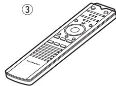
③ Remote control (RC001PMSA) 1
(4) R03/AAA batteries 2
⑤ Warranty card (for USA) 1
⑥ Warranty card (for CANADA) 1
About this manual
Operation buttons
The operations described in this manual are based mainly on remote control operation.
□ Symbols

This symbol indicates a reference page on which related information is described.

This symbol indicates a supplementary information and tips for operations.
NOTE
This symbol indicates points to remember operations or function limitations.
□ Illustrations
Note that the illustrations in these instructions are for explanation purposes and may differ from the actual unit.
Cautions on handling
- Before turning the power on
-
Check once again that all connections are correct and that there are no problems with the connection cables.
-
Power is supplied to some of the circuitry even when the unit is set to the standby mode. When going on vacation or leaving home for long periods of time, be sure to unplug the power cord from the power outlet.
- About condensation
If there is a major difference in temperature between the inside of the unit and the surroundings, condensation (dew) may form on the operating parts inside the unit, causing the unit not to operate properly.
If this happens, let the unit sit for an hour or two with the power turned off and wait until there is little difference in temperature before using the unit.
- Cautions on using mobile phones
Using a mobile phone near this unit may result in noise. If that occurs, move the mobile phone away from this unit when it is in use.
- Moving the unit
Turn off the power and unplug the power cord from the power outlet. Next, disconnect the connection cables to other system units before moving the unit.
- About care
- Wipe the cabinet and control panel clean with a soft cloth.
- Follow the instructions when using a chemical cleaner.
- Benzene, paint thinner or other organic solvents as well as insecticide may cause material changes and discoloration if brought into contact with the unit, and should therefore not be used.
About the remote control
The supplied remote control can be used to control marantz Integrated Amplifier and marantz Super Audio CD player.
- The remote control may not operate some products.
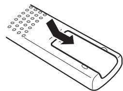
Inserting the batteries
(1) Remove the rear lid in the direction of the arrow and remove it.
② Load the two batteries properly as indicated by the marks in the battery compartment.
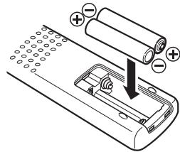
③ Put the rear cover back on.
NOTE
- Insert the specified batteries in the remote control unit.
- Replace the batteries with new ones if the set does not operate even when the remote control unit is operated close to the unit. (The supplied batteries are only for verifying operation. Replace them with new batteries at an early date.)
- When inserting the batteries, be sure to do so in the proper direction, following the and marks in the battery compartment.
-
To prevent damage or leakage of battery fluid:
-
Do not use a new battery together with an old one.
- Do not use two different types of batteries.
- Do not attempt to charge dry batteries.
- Do not short-circuit, disassemble, heat or dispose of batteries in flames.
- Do not keep the battery in a place exposed to direct sunlight or in places with extremely high temperatures, such as near a heater.
- If the battery fluid should leak, carefully wipe the fluid off the inside of the battery compartment and insert new batteries.
- Remove the batteries from the remote control unit if it will not be in use for long periods.
- Used batteries should be disposed of in accordance with the local regulations regarding battery disposal.
- The remote control unit may function improperly if rechargeable batteries are used.
Operating range of the remote control unit
Point the remote control unit at the remote sensor when operating it.
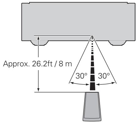
NOTE
- The set may function improperly or the remote control unit may not operate if the remote control sensor is exposed to direct sunlight, strong artificial light from an inverter type fluorescent lamp or infrared light.
- When using 3D video devices that transmit radio communication signals (such as infrared signals etc) between the various units (such as the monitor, 3D glasses, 3D transmitter unit etc), the remote control unit may not operate due to interference from those radio communication signals. If this occurs, adjust the direction and distance of the 3D communication for each unit, and check that the remote control unit operation is not affected by these signals.
Features
HDAM®SA3 Module
This unit includes the HDAM®SA3 which had been developed for high-end models. The HDAM®SA3 is incorporated into many components, such as the current feedback phono equalizer, balance buffer, and input buffer.
Constant Current Feedback Phono Equalizer
This unit incorporates the constant current feedback phono equalizer which had been developed for high-end models. This equalizer, developed by marantz, has the advantages of both NF-type and CR-type phono equalizers, and it supports both MM and MC cartridges.
Current Feedback Balance Buffer Amplifier
The Current Feedback Balance Buffer Amplifier, which incorporates the HDAM®SA3 amp module, is provided with this unit, in order to faithfully convey signals from Super Audio CD players and D/A converters that have high-quality balanced output.
Dedicated Input Buffers for All Line Input Jacks
Each CD, LINE 1, LINE 2, REORDER 1, and REORDER 2 input jack has its own input buffer amplifier that incorporates an HDAM®SA3. These amplifiers' arrangement are circuit designed close to the respective jacks. Therefore, each input signals are faithfully conveyed without interference between them.
Linear Control Volume
The control knob had adopted the high-end model design concept. For better S/N ratio, the MAS6116 from Micro Analog Systems and the HDAM®SA3 have been combined, which enables smooth adjustment in the range of 0 to -100 dB in units of ±0.5 dB.
Tone Control Amplifier
The electronic tone control amplifier is provided for adjustment of bass (low frequency) and treble (high frequency) sound in units of 2 dB in the range of -8 to +8 dB.
Dual-Amplifier Structure
Amplifier of this unit has dual structure, voltage amplifier and power buffer, adopting high-end model design concept. This dual structure enables the power buffer amplifier to drive the speakers powerfully, preventing influence from the back electromagnetic force from the speakers. The voltage amplifier drives the power buffer with superlow distortion.
New-Designed Current Feedback Power Amplifier
To minimize noise of power amplifier, circuit design with lower impedance is incorporated. This enables the user to obtain natural acoustics.
F.C.B.S.
A Floating Control Bus System (F.C.B.S.) enables the user to connect up to four PM-11S3 units, making a diversity of applications possible with complete bi-amp and multichannel connections. Moreover, a ground loop is not formed among multiple PM-11S3 units connected; therefore, sound quality is not adversely affected.
BI-AMP Mode
Complete bi-amp connection proposed by marantz enables a level of reproduction of the acoustic field never before achieved. Synchronized operation of two PM-11S3 units is made possible by F.C.B.S. (Floating Control Bus System) connection, with each PM-11S3 in Bi-Amp mode working as a monaural integrated amplifier.
Power Amplifier Direct In Mode
In this mode, this unit works as a power amplifier. This mode will be useful in home theater systems.
Display
This unit adopts an LCD (Liquid Crystal Display) to display the input source and volume level. Compared with other types of display panels, an LCD requires less drive power and generates less radiation noise, which minimizes any adverse effect on sound quality.
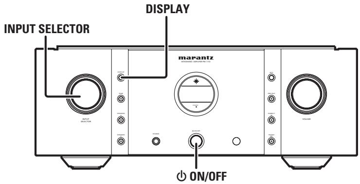
Part names and functions
For buttons not explained here, see the page indicated in parentheses ( ).
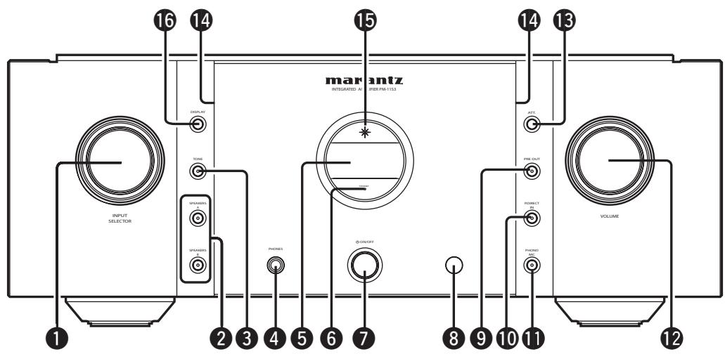
Front panel
1 INPUT SELECTOR knob (11)
Speaker output switch button (SPEAKERS A, SPEAKERS B) (11)
TONE button (12)
4 Headphone jack (PHONES) (13)
⑤ Display
Standby status indicator Indicates the status of the unit's as follows:
- Power "ON". Off
- Standby............Red
- Power "OFF". Off
Power switch (ON/OFF) (11)
Remote control sensor (2)
PRE OUT switch button (19)
10 Power amplifier direct mode switch button (P.DIRECT IN) (19)
11 Phono equalizer switch button (PHONO MC) (9)
12 VOLUME knob (11)
13 Attenuator button (ATT.) (13)
14 Illumination lamp (13)
15 Power indicator.. (11) Indicates the status of the unit's as follows:
- Power “ON”............ Blue
- Standby.
- Power "OFF". Off
16 DISPLAY button (13)
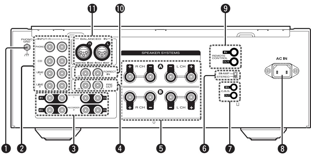
Rear panel
1 PHONO GND (ground) terminal (9)
NOTE
This terminal is not a safety ground.
2 Input terminals (INPUT) (9)
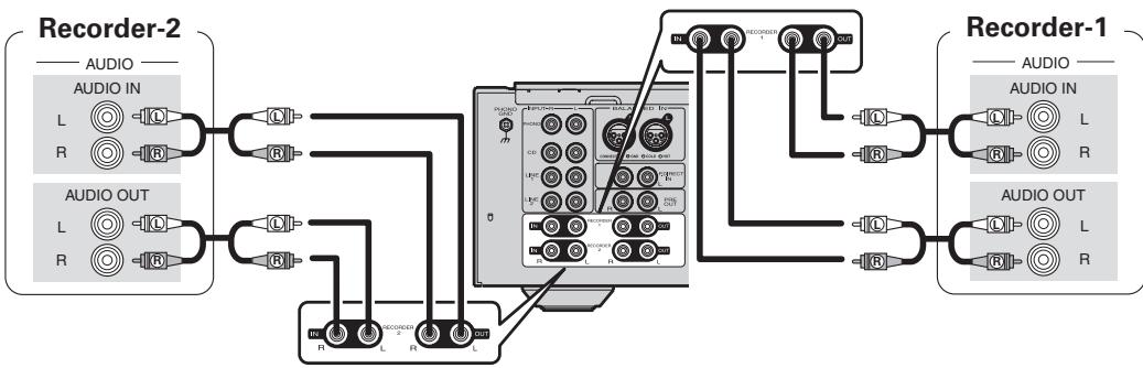
Input/output terminals (Recordings) (RECORDER1, RECORDER2) (10)
4 PRE OUT terminals (19)
Speaker system terminals (SPEAKER SYSTEMS) (7, 8)
⑥ Amplifier mode switch (16)
F.C.B.S. terminals (14)
AC inlet (AC IN) (10)
9 REMOTE CONTROL terminals (20)
10 Power amplifier direct terminals (P. DIRECT IN) (19)
11 Balanced input terminals (9)
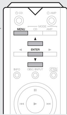
Remote control
□ Buttons for amplifier
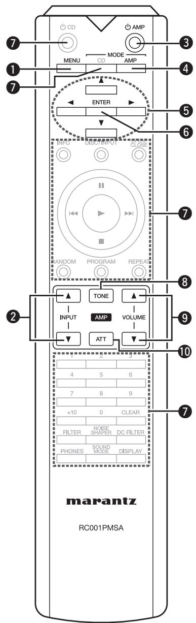
1 MENU button (12)
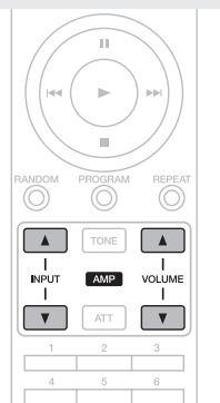
Input selector buttons (INPUT) (11)
③ Amplifier power button (AMP) ……(11)
Remote control mode switch button (MODE AMP) (12)
Cursor buttons ( ) (12)
6 ENTER button (12)
7 Buttons for Super Audio CD player
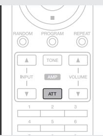
8 TONE switch button (12)
9 VOLUME buttons ( ) (11)
10 Attenuator button (ATT) (13)

- The supplied remote control can be used to control marantz Integrated Amplifier and marantz Super Audio CD player.
- When using this remote control, also refer to the operating instructions of the other devices.
NOTE
The remote control may not operate some products.
□ Buttons for Super Audio CD player
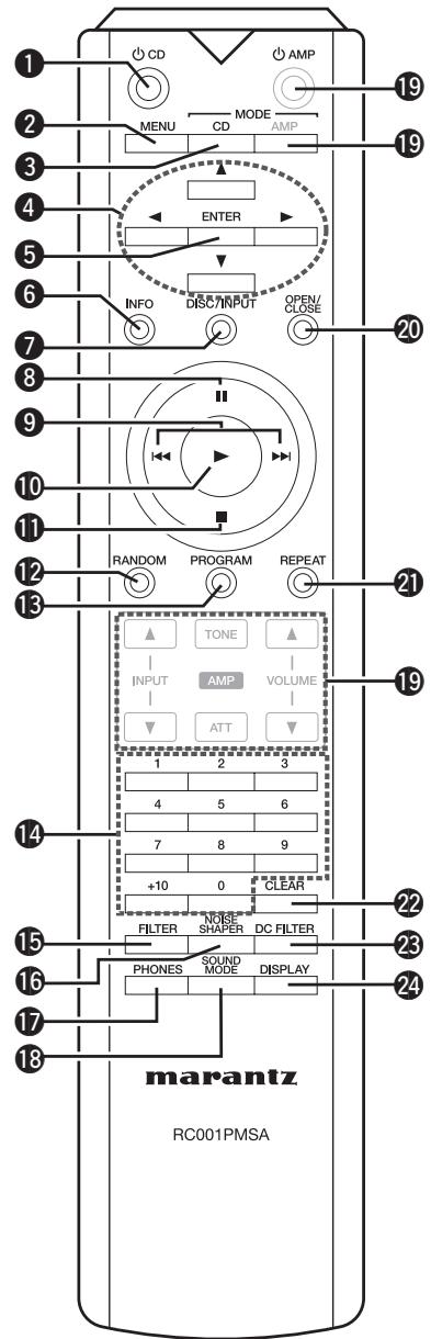
Super Audio CD player power button (CD)
2 MENU button
Remote control mode switch button (MODE CD)
4 Cursor buttons (▲▼▲▶)
ENTER button
Information display switch button (INFO)
Input selection button (DISC/INPUT)
8 Pause button (II)
9 Skip buttons (I<, ▷>I)
10Playback button ()
Stop button (■)
12 RANDOM button
13 PROGRAM button
14 Numeric buttons (0 - 9, +10)
15 FILTER button
16 NOISE SHAPER button
PHONES button
18 SOUND MODE button
19 Buttons for amplifier
20 Disc tray OPEN/CLOSE button
REPEAT button
CLEAR button
DC FILTER button
24 DISPLAY button
Basic connections
NOTE
- Do not plug in the power cord until all connections have been completed.
- When making connections, also refer to the operating instructions of the other components.
- Be sure to connect the left and right channels properly (left with left, right with right).
- Do not bundle power cords with connection cables. Doing so can result in humming or noise.
- Do not turn up the volume without a turntable connected to the PHONO input terminals. Doing so will cause humming or noise.
Preparations
Connecting cables
Select the cables according to the equipment being connected.
Audio cables
Analog connections (UNBALANCED)
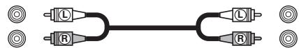
Pin-plug cable (sold separately)
Analog connections (BALANCED)
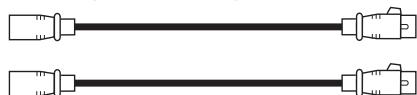
Balance cables (sold separately)
Speaker connections

Speaker cables (sold separately)
Connecting the audio equipment
Cautions on playing SA sources:
When regular speakers not compatible with SA sources (DVD Audio discs, Super Audio CDs and other sources, including treble components above the audible range), set the properties of the player (DVD Audio player, Super Audio CD player, etc.) for use with regular speakers (or amplifiers). The speakers may be damaged if the volume is set too high when playing SA sources. For instructions on player settings, refer to the operating instructions included with the player.
Connecting the speakers
Connecting the speakers cables
Carefully check the left (L) and right (R) channels and + (red) and - (white) polarities on the speakers being connected to the unit, and be sure to connect the channels and polarities correctly.
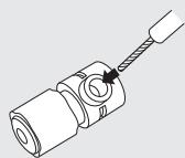
1 Peel off about 0.03ft / 10mm of sheathing from the tip of the speaker cable, then either twist the core wire tightly or apply solder to it.

2 Turn the speaker terminal counterclockwise to loosen it.
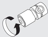
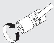
3 Insert the speaker cable's core wire to all the way into the speaker terminal.
4 Turn the speaker terminal clockwise to tighten it.
Spade lug connector
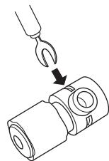
When using a banana plug
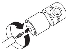
Tighten the speaker terminal firmly before inserting the banana plug.
NOTE
- Connect the speaker cables so they do not stick out of the speaker terminals. The protection circuit may be activated if the wires touch the rear panel or if the + and - sides touch each other (page 21 "Protection Circuit").
- Never touch the speaker terminals while the power supply is connected. Doing so could result in electric shock.
Speaker impedance
Use speakers with impedances within the ranges shown below to suit how they are used.
| Speakers used | Impedance |
| A | 4 – 16 Ω |
| B | 4 – 16 Ω |
| A and B | 8 – 16 Ω |
| Bi-wiring Connection | 8 – 16 Ω |
Protection circuit
The protection circuit is be activated in the following situations:
- If the speaker cable wire touches the rear panel or screws or if the speaker cable wire touches the speaker cable's + and - sides are touching
- If the surrounding temperature is extremely high
- If the inside of the amplifier gets hot to extended use at a high output
If this happens, unplug the power cord, then check the connections of the speaker cables and input cables.
If the unit becomes very hot, wait for it to cool off and improve the ventilation around it. After doing this, plug the power cord back in.
If the protection circuit is activated even though there are no problems with the ventilation around the unit or in connections, the unit may be damaged. Turn off the power and then contact a marantz service center.
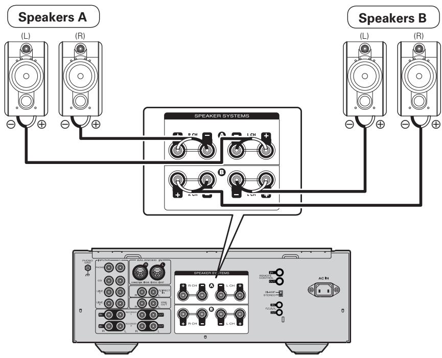
Speaker connections
- The same signal is output from the SPEAKER A and B terminals.
- When only one set of speakers is to be connected, use either the SPEAKER A or B terminals.
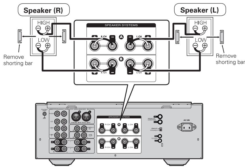
Bi-wiring connection
- When bi-wiring with bi-wireable speakers, connect the mid and high range terminals to SYSTEM (A) (or SYSTEM (B)), the low range terminals to SYSTEM (B) (or SYSTEM (A)).
- This enables playback with minimal interference between the high-range speaker unit and the low-range speaker unit.
Connecting players
Set phono equalizer switch button by the type of your cartridge to be used MM or MC.
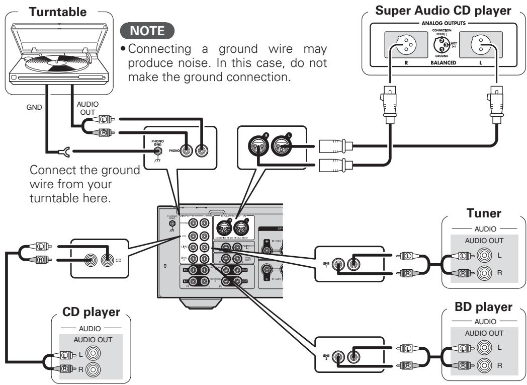
BALANCED Jacks
The BALANCED jacks on this unit are equipped with XLR connectors that are widely used on professional equipment. Their features are listed below.
- The 3 pin construction enables the musical signal to be transmitted as a balanced signal, with little effect from external noise
- The detachable locking mechanism minimizes connector play and enhances connection reliability.
The XLR connector for professional use is internally wired in either of the following two systems.
- USA system (② PIN=COLD ③ PIN=HOT)
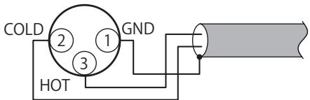
- European system (② PIN=HOT ③ PIN=COLD)
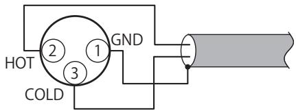
If a product that employs the European system is connected with this unit via a balanced cable, the reproduced signal may be phase-inverted.
To correct the inversion, connect the one side XLR connector reversing the ② PIN and ③ PIN.
Connecting recorders
Connecting the power cord
Do not plug in the power cord until all connections have been completed.
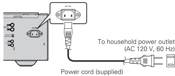
NOTE
Insert the plugs securely. Loose connections will result in the generation of noise.
Basic operation
Before use
Turning the power on
Press ON/OFF on the unit.
- Power is turned on.
The power indicator lights in blue. - The unit will be ready to start playback after several seconds.
Turning the power standby
Press AMP.
The power is set to the standby mode.
The Standby status indicator lights in red.
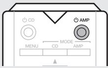

- Press AMP to turn on power from standby mode.
- You can also turn on power by using either INPUT SELECTOR on this unit from standby mode.
NOTE
Power continues to be supplied to some of the circuitry even when the power is in the standby mode. When leaving home for long periods of time or when going on vacation, either press ON/OFF to turn off the power, or unplug the power cord from the power outlet.
Turning the power off
Press ON/OFF on the unit.
- Power is turned off.
- All indicators will turn off.
Starting playback
1 Press SPEAKERS A/SPEAKERS B on the unit to select the speaker system to be used for playback.
2 Use INPUT SELECTOR on the unit or INPUT on the remote control to select the source.
- The input source changes as follows with each press of the button:
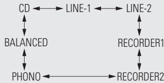
3 Start playing back the source.
4 Adjust the VOLUME on the unit or remote control to the desired level.
Adjusting the levels
Left and right channel balance
The volume level of the left and right channels can be trimmed in 0.5 dB steps across a 0.0 - 9.0 dB range. When the unit is shipped from the factory, the volume level is set to 0.0 dB (maximum).
1 Press MENU. The unit enters the level adjustment mode.
- The left channel level value flashes.

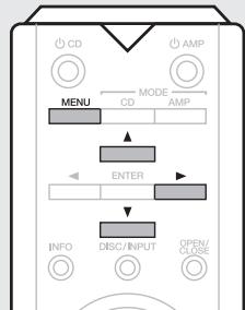
2 Press to adjust the left channel level.

3 Press. The adjustment mode selects the right channel.
- The tight channel level value flashes.

4 Press to adjust the right channel level.
Press MENU. The unit exits the adjustment mode.
- If you have connected a "SLAVE" device using the F.C.B.S. connection (B page 14), proceed to the slave setting.
Adjusting the tone
Low frequency range
The low frequency range can be trimmed in 2 dB steps across a -8 + + 8 dB range. When the unit is shipped from the factory, the level is set to 0.0dB . Before making this adjustment, press TONE on the unit or the remote control to set the tone control to on.
1 Press MENU. The unit enters the level adjustment mode.
2 Press ENTER. The adjustment mode selects the low frequency range.

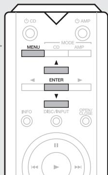
Press to adjust the level.

- If not operated for 15 seconds, the current setting is saved and the display returns to normal.
High frequency range
The high frequency range can be trimmed in 2 dB steps across a -8 - +8 dB range. When the unit is shipped from the factory, the level is set to 0.0dB . Before making this adjustment, press TONE on the unit or the remote control to set the tone control to on.
Press MENU.
The unit enters the level adjustment mode.
Press ENTER twice.
The adjustment mode selects the high frequency range.

Press ▲▼ to adjust the level.

- If not operated for 15 seconds, the current setting is saved and the display returns to normal.
NOTE
Before making the adjustment for level and tone, press MODE/AMP to set its control mode to amplifier.
Muting the sound
Sound can be muted temporarily.
Press ATT.
"ATT" appears on the display and the sound is muted.

- To restore the sound, press the button again.
How to Set Attenuation Level
- Attenuation level can only be set using ATT on the unit.
The attenuation level can be set at -20dB -40dB or -
The factory default setting is -20dB
Press and hold ATT on the unit for 2 seconds or longer.
The attenuation level will appear on the display.

Press ATT on the unit.
Each time the button is pressed, the attenuation level changes as follows:

- If not operated for 2 seconds, the current setting is saved and the display returns to normal.
Using headphone set
Plug headphones into PHONES jack.
- When using headphones, turn off the speaker output using SPEAKERS A/SPEAKERS B.
- To prevent hearing loss, do not raise the volume level excessively when using headphones.
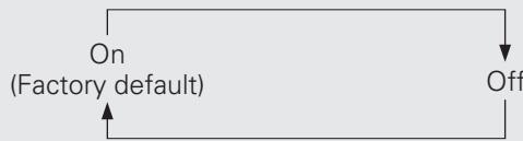
Switching the illumination lamp setting
The illumination lamps on the both sides of the unit main panel can be turned on or off.
Press and hold DISPLAY on the unit for 2 seconds or longer.
The on/off setting changes as follows with each press of the button.
Advanced connections
F.C.B.S. connection
The marantz F.C.B.S. (Floating Control Bus System) is the high quality sound system for link control between multiple PM-11S3 units (up to 4 units). Each unit is controlled via its ID number registered beforehand.
The ID numbers need to be set to an operating unit (master) and a subordinate unit (slave) receiving the command from the master. For slave units, register ID numbers in the order of command reception from the master.
Once registered the ID numbers, the units will enable link control operations such as input selection, volume control, on/off selection of muting, display, tone control, etc.
Furthermore, F.C.B.S. connection of multiple units has the feature that switches this unit's output from stereo to monaural so that the unit can works as a monaural output amplifier.
Follow the respective instructions to make the necessary settings.
Preparation for F.C.B.S. connection
Making the F.C.B.S. connection
To use multiple PM-11S3 units, make this connection in addition to audio connection.
For details on each connection feature, refer to the respective instructions.
Prepare the correct number of portable audio connection cables for the number of units to be connected. Either of the following types of connection cables are adequate.
Do not use connecting cables that contain resistance.
Connection example
In the connection of the following example, an unit with ID number 1 acts as a master amplifier to control all the other slave units with ID numbers 2 to 4.
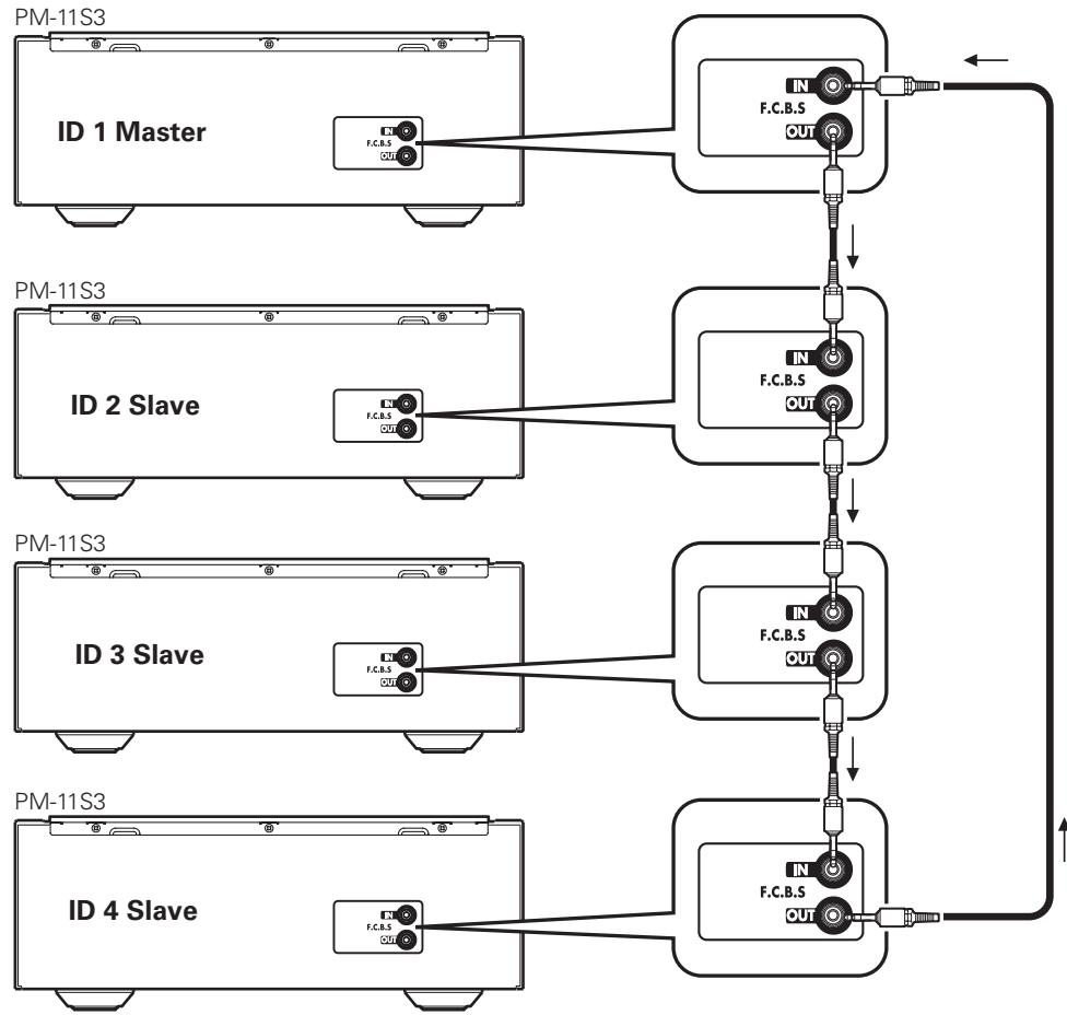
NOTE
- The PM-11S3 F.C.B.S. function is only valid between the same PM-11S3 models. This function may not operate correctly if other marantz models (PM-11S2, etc.) are connected.
- To turn the power of multiple F.C.B.S.-connected units ON/OFF, switch the power ON in order of lowest to highest ID number, and switch the power OFF in order of highest to lowest ID number.
How to set ID number for F.C.B.S.
When the unit is turned on, the display shows the ID number for three seconds.

For a master unit, ID number 1 needs to be assigned.
For a slave unit, set any of ID numbers 2 to 4.
1 While holding DISPLAY on the unit, press ON/OFF.

2 Turn INPUT SELECTOR on the unit to select an ID number.

3 Turn the unit off.
4 Again turn the unit on. The setting is saved.
- The unit registered as a slave shows "SLAVE" on the display.
NOTE
- If using this unit by itself as a stereo amplifier, set the ID number to "0" (Default setting is "0").
- If the ID number is set to a number other than "0", this unit cannot be used for standalone operation.
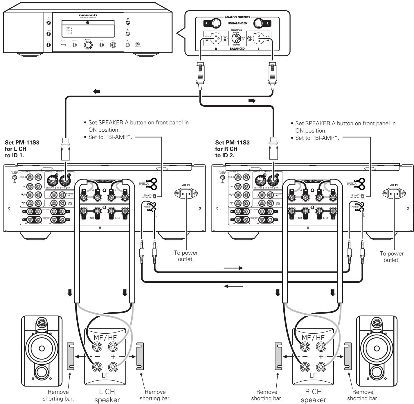
Stereo complete bi-amp connection
This mode enables the two amplifiers connected to this unit to function as one monaural amplifier. To use this mode, two F.C.B.S. connected PM-11S3 units are required.
To switch the mode, use the amplifier mode switch on the rear panel while the power is off.

The figures below show example displays in the stereo and bi-amp modes.

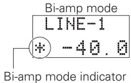
In bi-amp mode, connect to the left channel input jack. The right channel input is disabled.
The same signals are output from the left and right output jacks.
NOTE
- Always turn the power to the unit OFF before changing the operating mode switch setting. Turning the power ON again activates the new setting.
- When in bi-amp mode, the R channel input jacks cannot be used.
- When in bi-amp mode, the signals input into the L channel are output from both channels. Therefore, the same signals are output from the L channel and R channel in RECORD OUT, PRE OUT, PHONES OUT.
- Speaker systems connected using complete bi-amp connections must support bi-amp connections. Before connecting your speakers, check in the instruction manual that came with the speakers or contact the manufacturer to confirm whether they support bi-amp connection.
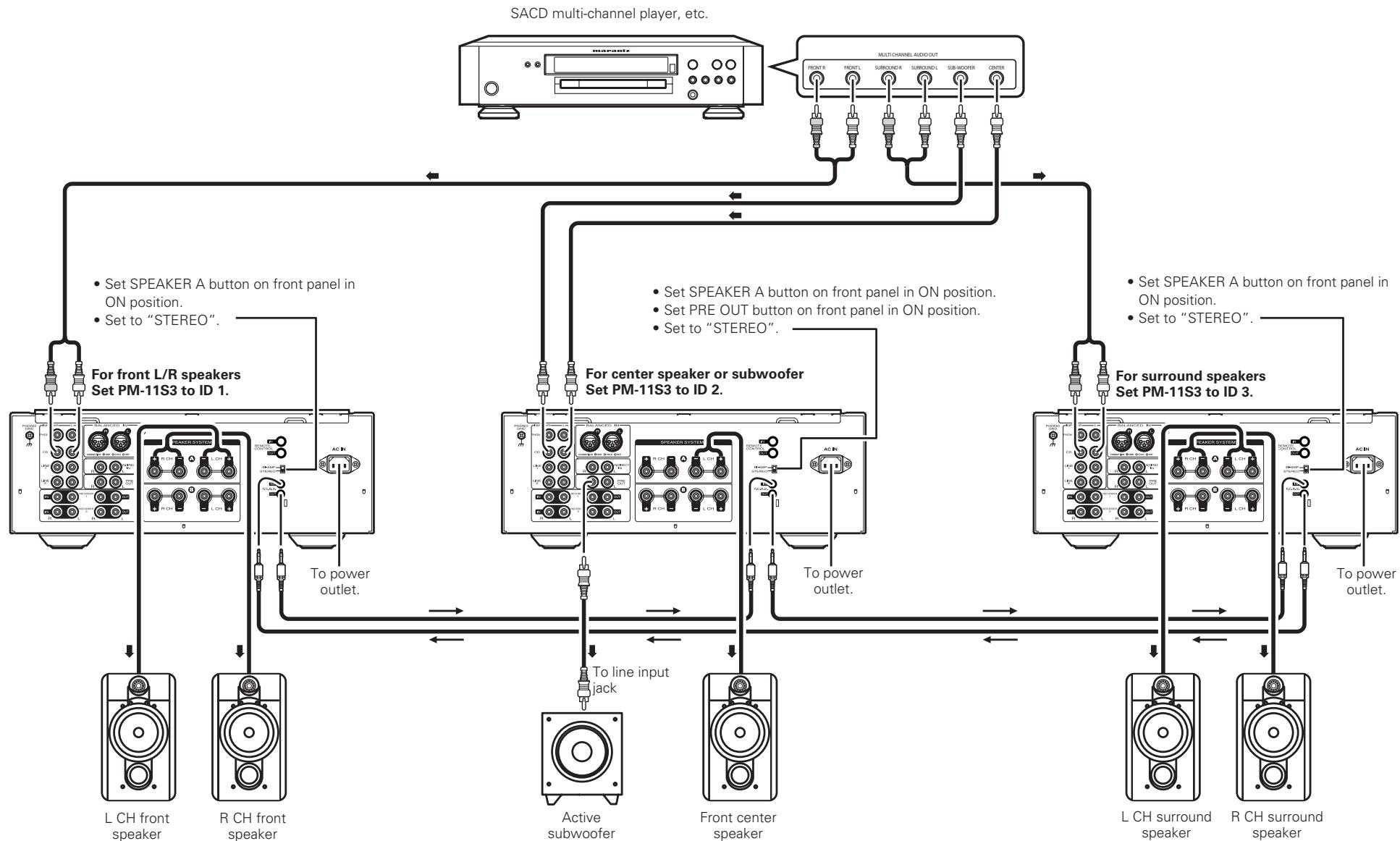
Connection for 5.1 Multi-channel Playback
The three units are connected using F.C.B.S. For the F.C.B.S connection, prepare 3 audio connection cables, and refer to F.C.B.S. ( page 14).
Connect the outputs of players that have 5.1 channel analog outputs to each of the three units.
If using an active subwoofer, see the instruction manual that came with the subwoofer for further instructions.
Set the ID numbers for the three amplifiers as explained in How to set ID number for F.C.B.S. (10 page 15).
- When the ID 1 unit is operated, ID 2 and ID 3 units will operate in sync.
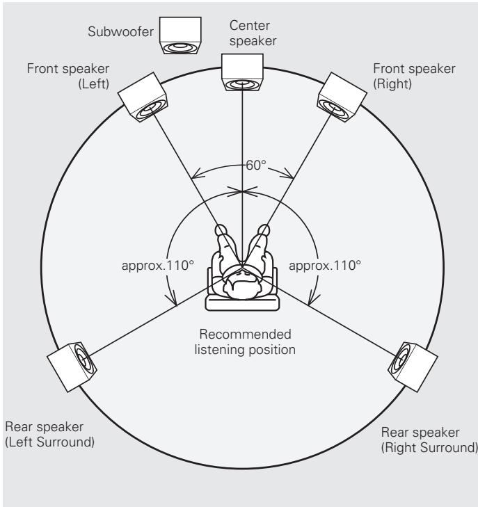
Speaker Positioning for Super Audio Multi-channel Sound
In order to enjoy Super Audio CD multi-channel sound with the best possible acoustics, it is recommended to position speakers as specified in ITU-R BS.775-1 of the International Telecommunication Union (ITU). Super Audio CD multi-channel discs are recorded and mixed so as to achieve the optimum effect with a speaker system laid out as specified in ITU-R BS.775-1.
- With Super Audio CD multi-channel discs, the music signals are basically recorded using 5 channels (3 - 6 channels sometimes), but in some cases, LFE (for subwoofer) is recorded as a sixth channel.
Each disc indicates how many channels have been recorded on it. - The basic layout is 3 speakers in the front and 2 in the back since multi-channel discs usually have 5 channels. The 2 front, 1 center and 2 surround (rear) speakers should be set in a circle around the listening point. If using speakers of differing sizes, adjust volume balance from the amplifier.
- The location of the subwoofer in the figure is just for explanatory purposes. It can be located anywhere in the room. For connection and positioning instructions, see the instruction manual that came with the subwoofer.
- ITU (International Telecommunication Union)
The ITU is a special organization of the United Nations. It consists of a number of organs, one of which is the Radio Broadcasting Section.
ITU-R BS in the recommendation which consists of standards relating to broadcasting (audio) operations, one of which is the ITU-R BS.775-1 which governs "multi-channel stereo sound systems".
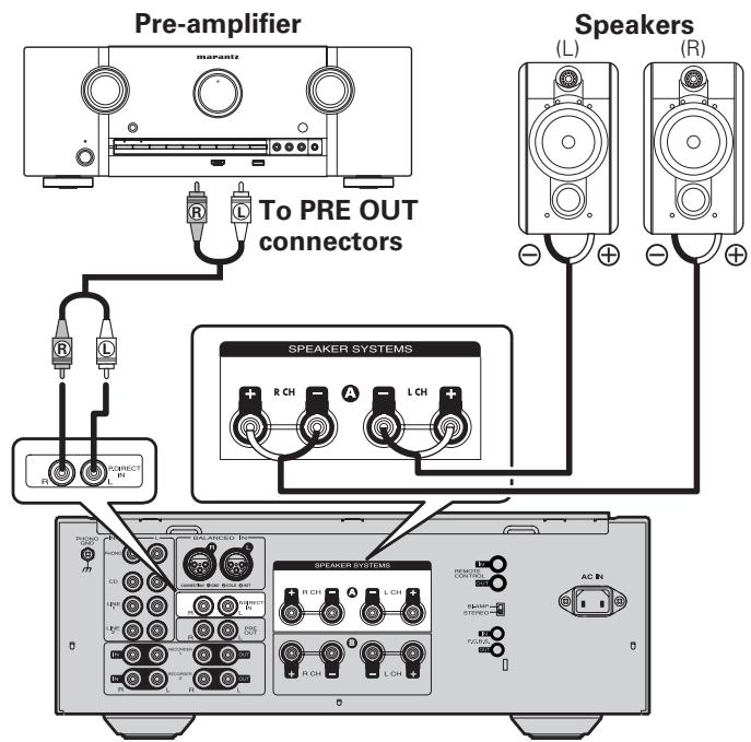
Connecting P.DIRECT IN connectors
If you use a preamplifier, connect it as shown below, and then you can use this unit as a power amplifier.
Press and hold P.DIRECT IN on the unit for 2 seconds or longer.
- The power direct mode setting changes with each press of the button.
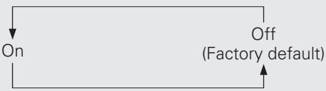
- If the mode is set to on, the display shows "POWER AMP DIRECT".
On: Allows the device connected to the Power Amp Direct connector to be played.
Off: Allows the program source selected using INPUT SELECTOR to be played.
NOTE
- When the POWER AMP DIRECT is "ON", adjustment of the volume, balance and tone on the main unit has no effect. Adjust the volume on the pre-amplifier.
- When the POWER AMP DIRECT is "ON", the main unit outputs at maximum volume. Check the output level on the input device before playing it and adjust the volume accordingly.
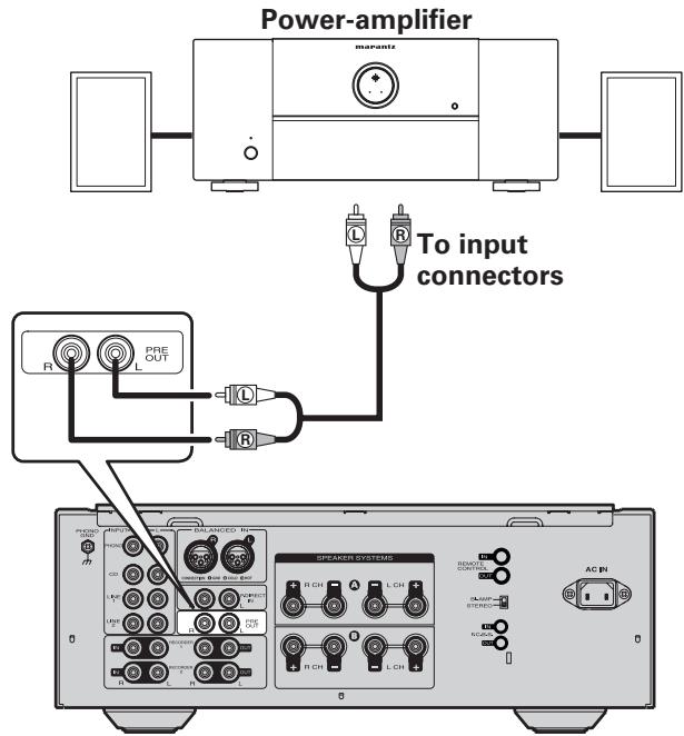
Connecting pre out connectors
If you use a power amplifier, connect it as shown below, and then you can use this unit as a preamplifier.
- Press the PRE OUT switch button on this unit to turn on the PRE OUT function.
- For connecting speaker systems, refer to the instruction manual supplied with the power amplifier to be used.
NOTE
The power amp direct function and the pre out function cannot work at the same time.
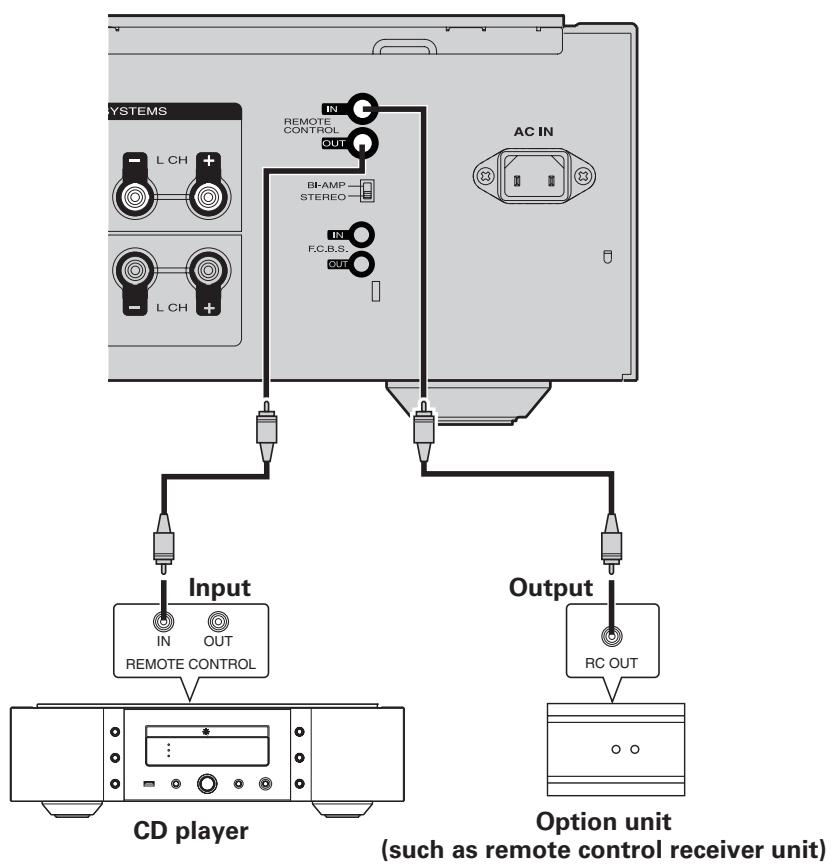
Connecting the remote control connectors
When you use this unit connected to marantz audio components, it sends control signals to operate each component.
Connection
Use the remote connection cable (supplied with a marantz audio component you want to connect) to connect the REMOTE CONTROL OUT terminal of this unit to the REMOTE CONTROL IN terminal of the component to be connected.
□ Setting
Set the remote control switch located on the rear panel of the connected audio component to "EXTERNAL" or "EXT." to use this feature.
- This setting will disable remote sensor reception of the connected audio component.
- To operate the connected audio component, point the remote control at the remote sensor of this unit.
- To use the system control to this unit via the connected device, make the connection following the instructions supplied with the connected device.
Advanced operations
Setting Auto standby mode
With the Auto standby mode ON, this unit will automatically enter the standby mode after about 30 continuous minutes of no output from the selected input source.
Press and hold TONE on this unit for 5 seconds or longer.
- Auto standby mode is switched between On and Off with each press of the button.
- If the mode is set to off, the display shows "AUTO STBY OFF".

- This unit will automatically enter standby mode after about continuous 30 minutes in the following conditions.
- No operation performed on the remote control.
- No operation of this unit.
- The display will show the remaining time for three minutes before the units enters standby mode.
- In F.C.B.S. connection, only the ID 1 master unit activates Auto standby mode. If the ID 1 master unit is operated with no audio input, set the Auto standby mode to OFF.
Explanation terms
MM/MC cartridge select
There are two types--MM (Moving Magnet) and MC (Moving Coil)--of cartridges for turntable.
As the output levels for these two types of cartridges differ, the setting of the phono equalizer that is mounted in this unit must be switched according to the type of cartridge for your turntable. For switching, use the PHONO MC button on this unit.
Speaker impedance
This is certain-rated resistance of the speaker set to an alternating current and expressed in ohms.
The smaller the impedance, the greater the output. However, load on the amplifier is increased. Use speakers whose impedance is supported by this unit
Bi-wiring Connection
This method of connecting a speaker by using two speaker cables enables separate transmission of treble and bass signals.
This enables playback with minimal interference between the high-range speaker unit and the low-range speaker unit.
Protection Circuit
This is a function to prevent damage to components within the power supply when an abnormality such as an overload or excess voltage occurs for any reason.
In this unit, the power indicator blinks and the unit enters standby mode when an abnormality occurs.
Troubleshooting
Troubleshooting
About the protection circuit
This unit is equipped with a protection circuit to protect the amplifier circuits and speaker system from damage.
If the protection circuit is activated, the sound is instantly muted.
In this case, the message "PROTECT" flashes on the display panel, and the STANDBY indicator also flashes.
To deactivate the protection circuit, turn the unit off then back on again after about 1 minute or more.
At power on
For about 8 seconds after the power is turned on, the protection circuit is activated, muting the sound to give the amplifier circuits time to stabilize. Once the amplifier circuits stabilize, the protection circuit is released, and audio is enabled.
In the event of overcurrent
The protection circuit is activated if current exceeding a certain level is detected, which can happen if excessive signal flow is input to the amplifier or if the unit is connected to a speaker system of less than 4 impedance. The protection circuit is also activated if a speaker cable shorts.
In such cases, the message "PROTECT" flashes on the display, and the volume is automatically reduced. After approximately 8 seconds, the protection circuit is released. Therefore, the volume needs readjusting to continue normal use.
If the overcurrent continues, the amplifier shuts itself OFF, and the STANDBY indicator flashes.
To deactivate the protection circuit, turn the unit off then back on again after about 1 minute or more.
If excessive ultrabass signals are input
The protection circuit is also activated if ultrabass signals are input. In such a case, the STANDBY indicator flashes, and the volume is automatically reduced. After approximately 8 seconds, the protection circuit is released. Therefore, the volume needs readjusting to continue normal use. If excessive ultrabass signal input continues or if DC voltage is detected owing to trouble with the amplifier, the amplifier shuts itself OFF, and the STANDBY indicator flashes.
To deactivate the protection circuit, turn the unit off then back on again after about 1 minute or more.
If the main-amplifier overheats
The protection circuit is activated if the temperature of the main amplifier section rises above a certain level, which can happen if the amplifier is continuously used with excessive signal flow being input to it. The protection circuit is also activated when the specified operating temperature is exceeded, which can happen if the vents on top of the amplifier are covered or if the amplifier is installed on a cramped audio rack. In such a case, the STANDBY indicator flashes, and the volume is automatically reduced. After approximately 8 seconds, the protection circuit is released. Therefore, the volume needs readjusting to continue normal use.
If the temperature does not sufficiently fall within a certain amount of time after the protection circuit activation, the amplifier shuts itself OFF, and the STANDBY indicator flashes. To deactivate the protection circuit, turn the unit off, let it stand until it cools down, then turn it ON again.
In the event of amplifier trouble
The protection circuit is activated, and the power is automatically shut OFF, if an abnormality is detected in the power circuit. The same happens if the main fuse inside the amplifier blows. In such cases, the STANDBY indicator flashes. Turn the unit off then after several minutes turn it on again. If the display does not light up, and the STANDBY indicator remains flashing after the unit is turned on again, the unit may be in failure.
□ Error messages
When multiple amplifiers are connected by F.C.B.S., the error messages described in the table below may be displayed on the display. In such a case, ID number setting or remote cable connection may be in failure. Check the ID number or remote cable connection, referring to the table below. For details on ID number setting, see "How to set ID number for F.C.B.S."
(1 page 15).
| Indication | Meaning | |
| 1 | ERROR 02 | Multiple amplifiers take ID No. 2. |
| 2 | ERROR 03 | Multiple amplifiers take ID No. 3. |
| 3 | ERROR 04 | Multiple amplifiers take ID No. 4. |
| → Assign different ID numbers to the amplifiers. | ||
| 4 | ERROR 11 | The amplifiers with ID Nos. 2-4 cannot communicate with the amplifier with ID No. 1. |
| → If the amplifier with ID No. 1 is not on, turn it ON. | ||
| → Check that the remote cable is properly connected. | ||
| 5 | ERROR 12 | The amplifier with ID No. 1 cannot communicate with the amplifiers with ID Nos. 2-4. |
| → If multiple amplifiers take ID No. 1, set ID numbers properly. | ||
| → If the amplifier with ID No. 1 is connected to the amplifier with ID No. 0, set ID numbers properly. | ||
| → Check that the remote cable is properly connected. | ||
Are the connections correct?
□ Is the unit being operated as described in the owner's manual?
Are the other components operating properly?
If this unit does not operate properly, check the items listed in the table below. If the problem persist there may be a malfunction. In that case, disconnect the power immediately and contact your retail outlet.
| Symptom | Cause | Countermeasure | Page |
| When the power is turned on, the power indicator does not light and no sound is produced. | The power cord's plug is not fully plugged in. | Check the cord is securely inserted into the unit's AC inlet and the wall power outlet. | 10 |
| Power switches off suddenly while you are using the unit, the power indicator will flash in red at intervals of approximately 2 seconds. | The protection circuit will be activated depending upon the temperature rise in the internal parts of the unit. | Please switch off power at once, and re-apply the power after the body temperature has fallen sufficiently.Pleases re-install the unit in a place having good ventilation. | 72 |
| Power switches off suddenly while you are using the unit, the power indicator will flash red at intervals of approximately 0.5 seconds. | A speaker with impedance not supported by this unit is used.The protection circuit has been activated because the core wires of different speaker cables have touched each other or a core wire was slipped out of the terminal and is touching the unit's rear panel. | Please use speakers which have the specified impedance.Unplug the power cord, then after twisting the core wires together tightly again, or effecting termination treatments etc, please reconnect once again. | 77 |
| Even applying power, the power display flashes red at intervals of approximately 0.5 seconds. | The amplifier circuit in failure. | Switch off the power and please contact the marantz service adviser. | - |
| The power indicator lights but no sound is produced. | The speaker cables are not fully connected.The device you want to listen to has not been selected.The volume control is set to minimum.The input cable is not fully connected.The speaker output switch is set to OFF. | Connect securely.Insure the correct input is selected.Set to an appropriate level.Connect securely.Set the speaker output switch to ON. | 7111911 |
| Sound is only produced from the left or right speaker (s). | The speaker cables are not fully connected.The input cable is not fully connected.The left/right balance is off. | Connect securelyCONNECT securely%.Adjust to a proper balance with the balance control knob. | 7912 |
Troubleshooting
| Symptom | Cause | Countermeasure | Page |
| The left and right of stereo sound is reversed. | ·The connections of the speakers or input cables are reversed | ·Check the connections to be sure that left is connected to left, right to right. | 7 |
| Humming sound is heard in the music when playing turntable. | ·The player's ground wire is not connected. ·The cables are not fully connected to the PHONO terminals. ·Influence from a TV or VCR near the player. | ·Connect securely. ·Connect securely. ·Try changing the positions in which the devices are installed. | 9 9 - |
| Howling is produced along with the music if the volume is too high when playing turntable. | ·The player and speakers are too close together. ·The vibrations from the speakers are being transmitted to the player through the floor. | ·Install the player and speakers as far from each other as possible. ·Use cushions, etc., to absorb the speakers' vibrations. | - - |
| When playing turntable, the sound is distorted. | ·The needle pressure is incorrect. ·There is dirt on the tip of the needle. ·The cartridge is defective. | ·Adjust to a proper needle pressure. ·Check the tip of the needle. ·Replace the cartridge. | - - - |
| The remote control does not work. | ·The batteries are exhausted. ·The remote control unit is too far from the unit. ·There is an obstacle between the unit and the remote control unit. ·Button selection was mistaken. ·The batteries are not loaded with correct polarity (⊕, ⊙). | ·Replace the batteries with new ones. ·Operate closer to the unit. ·Remove the obstacle. ·Confirm the correct button to press. ·Correct the direction of the batteries according the polarity instruction. | 2 2 - - - 2 |
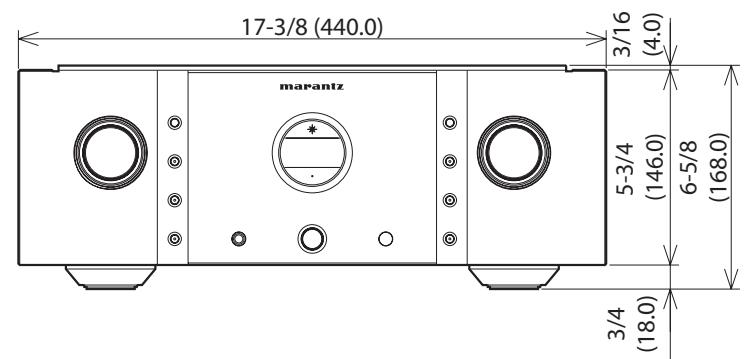
Specifications
RMS Power output: 100 W × 2 (8 Ω) (20 Hz - 20 kHz 2-channel simultaneously driven) 200 W × 2 (4 Ω)
- Total harmonic distortion: (20 Hz - 20 kHz 2-channel simultaneously driven, 8 Ω)
Output band width: (8, 0.05%)
Frequency response: (CD, 1 W, 8 Ω load)
Damping factor: (8, 20Hz - 20kHz)
- Input sensitivity/Input impedance
PHONO (MC): 260 μV / 100 Ω
PHONO (MM): 2.7 mV / 47 kΩ
BALANCED: 480 mV / 40 kΩ
CD/LINE: 240 mV / 20 kΩ
P. DIRECT IN: 1.7 V / 20 kΩ
- Output voltage/Output impedance PRE OUT: 1.9 V / 220 Ω
- Maximum allowable PHONO input level (1 kHz)
MC: 10 mV
MM: 105 mV
- RIAA deviation: (20 Hz - 20 kHz) ± 0.5 dB
- S/N (IHF-A, 8 Ω)
PHONO (MC): 76 dB (0.5 mV Input, 1 W Output)
PHONO (MM): 88 dB (5 mV Input, 1 W Output)
BALANCED: 109 dB (4 V Input, Rated output)
CD/LINE: 108 dB (2 V Input, Rated output)
- Tone control
BASS (50 Hz): ± 8 dB
TREBLE (20 kHz): ± 8 dB
- Power requirement: AC 120 V, 60 Hz
- Power consumption (UL60065): 300 W
- Standby power consumption: 0.2 W
For the purpose of improvement, the specifications and design are subject to change without notice.
Index


Accessories 1
Adjust the levels (Left and Right) 12
Adjust the tone 12
Adjust the volume 11
Auto standby mode 20


Batteries 2


Cable Balance cable 6
Pin- plug cable 6
Speaker cable 6
Condensation 2
Connection 5.1 Multi-channel Playback 17
Bi-wiring 8
Cables 6
Player 9
Power Amp Direct 19
Power cord 10
PRE OUT connectors 19
Recorder 10
Remote control connectors 20
Speaker 8
Stereo complete bi-amp 16


F.C.B.S. connection 14
Front panel 4


High frequency range 12

INPUT SELECTOR 11
Inserting the batteries 2

Low frequency range 12


MM/MC cartridge select 21
Muting the sound 13

Protection circuit 7, 21

Remote control 5

Speaker impedance 7, 21
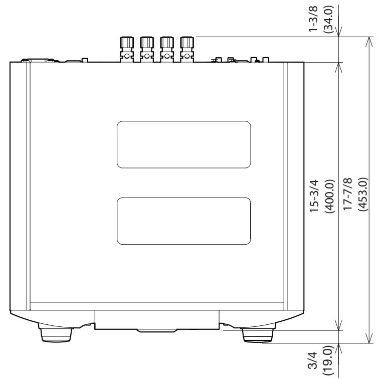
Unit / Unite / Unidad : inch (mm)
Weight / Poids / Peso : 58 lbs 10 oz (26.6 kg)
www.marantz.com
You can find your nearest authorized distributor or dealer on our website.
marantz® is a registered trademark.
- SAFETY PRECAUTIONS
- CAUTION
- RISK OF ELECTRIC SHOCK DO NOT OPEN
- CAUTION:
- WARNING:
- PRECAUTION:
- SURFACE CHAUBE. NE PASTOUCHER.
- FCC INFORMATION (For US customers)
- 1.PRODUCT
- IMPORTANT NOTICE: DO NOT MODIFY THIS PRODUCT
- NOTE
- For Canadian customers:
- Contents
- Getting started
- Basic connections 6
- Basic operation 11
- Advanced connections 14
- Advanced operations 20
- Explanation terms 21
- Troubleshooting 21
- Specifications 24
- Index 24
- Accessories
- About this manual
- Operation buttons
- □ Symbols
- NOTE
- □ Illustrations
- Cautions on handling
- - Before turning the power on
- - About condensation
- - Cautions on using mobile phones
- - Moving the unit
- - About care
- About the remote control
- Inserting the batteries
- Operating range of the remote control unit
- Features
- HDAM®SA3 Module
- Constant Current Feedback Phono Equalizer
- Current Feedback Balance Buffer Amplifier
- Dedicated Input Buffers for All Line Input Jacks
- Linear Control Volume
- Tone Control Amplifier
- Dual-Amplifier Structure
- New-Designed Current Feedback Power Amplifier
- F.C.B.S.
- BI-AMP Mode
- Power Amplifier Direct In Mode
- Display
- Part names and functions
- Remote control
- □ Buttons for amplifier
- □ Buttons for Super Audio CD player
- Basic connections
- Preparations
- Connecting cables
- Audio cables
- Analog connections (UNBALANCED)
- Analog connections (BALANCED)
- Speaker connections
- Connecting the audio equipment
- Cautions on playing SA sources:
- Connecting the speakers
- Connecting the speakers cables
- Spade lug connector
- When using a banana plug
- Speaker impedance
- Protection circuit
- Bi-wiring connection
- Connecting players
- BALANCED Jacks
- Connecting recorders
- Connecting the power cord
- Basic operation
- Before use
- Turning the power on
- Turning the power standby
- Turning the power off
- Starting playback
- Adjusting the levels
- Left and right channel balance
- Adjusting the tone
- Low frequency range
- High frequency range
- Press MENU.
- Press ENTER twice.
- Muting the sound
- Press ATT.
- How to Set Attenuation Level
- Press and hold ATT on the unit for 2 seconds or longer.
- Press ATT on the unit.
- Using headphone set
- Plug headphones into PHONES jack.
- Switching the illumination lamp setting
- Press and hold DISPLAY on the unit for 2 seconds or longer.
- Advanced connections
- F.C.B.S. connection
- Preparation for F.C.B.S. connection
- Making the F.C.B.S. connection
- Connection example
- How to set ID number for F.C.B.S.
- Stereo complete bi-amp connection
- Connection for 5.1 Multi-channel Playback
- Speaker Positioning for Super Audio Multi-channel Sound
- Connecting P.DIRECT IN connectors
- Press and hold P.DIRECT IN on the unit for 2 seconds or longer.
- Connecting pre out connectors
- Connecting the remote control connectors
- Connection
- □ Setting
- Advanced operations
- Setting Auto standby mode
- Press and hold TONE on this unit for 5 seconds or longer.
- Explanation terms
- MM/MC cartridge select
- Troubleshooting
- About the protection circuit
- At power on
- In the event of overcurrent
- If excessive ultrabass signals are input
- If the main-amplifier overheats
- In the event of amplifier trouble
- □ Error messages
- Are the connections correct?
- □ Is the unit being operated as described in the owner's manual?
- Are the other components operating properly?
- Specifications
- Index
- www.marantz.com
Brand : MARANTZ
Model : PM11S3
Category : Integrated amplifier