USER MANUAL ST7001 MARANTZ
CAUTION
RISK OF ELECTRIC SHOCK
DO NOT OPEN

CAUTION: TO REDUCE THE RISK OF ELECTRIC SHOCK, DO NOT REMOVE COVER (OR BACK)
NO USER-SERVICEABLE PARTS INSIDE
REFER SERVICING TO QUALIFIED SERVICE PERSONNEL
The lightning flash with arrowhead symbol within an equilateral triangle is intended to alert the user to the presence of uninsulated “dangerous voltage” within the product’s enclosure that may be of sufficient magnitude to constitute a risk of electric shock to persons.

The exclamation point within an equilateral triangle is intended to alert the user to the presence of important operating and maintenance (servicing) instructions in the literature accompanying the product.
WARNING
TO REDUCE THE RISK OF FIRE OR ELECTRIC SHOCK, DO NOT EXPOSE THIS PRODUCT TO RAIN OR MOISTURE.
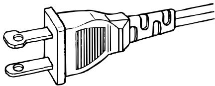
CAUTION: TO PREVENT ELECTRIC SHOCK, MATCH WIDE BLADE OF PLUG TO WIDE SLOT, FULLY INSERT.
ATTENTION: POUR ÉVITER LES CHOC ÉLECTRIQUES, INTRODUIRE LA LAME LA PLUS LARGE DE LA FICHE DANS LA BORNE CORRESPONDANTE DE LA PRISE ET POUSSER JUSQU'AU FOND.
NOTE:
This equipment has been tested and found to comply with the limits for a Class B digital device, pursuant to Part 15 of the FCC Rules. These limits are designed to provide reasonable protection against harmful interference in a residential installation. This equipment generates, uses and can radiate radio frequency energy and, if not installed and used in accordance with the instructions, may cause harmful interference to radio communications. However, there is no guarantee that interference will not occur in a particular installation. If this equipment does cause harmful interference to radio or television reception, which can be determined by tuning the equipment off and on, the user is encouraged to try to correct the interference by one or more of the following measures:
- Reorient or relocate the receiving antenna.
- Increase the separation between the equipment and receiver.
- Connect the equipment into an outlet on a circuit different from that to which the receiver is connected.
- Consult the dealer or an experienced radio/TV technician for help.
NOTE:
Changes or modifications not expressly approved by the party responsible for compliance could void the user's authority to operate the equipment.
NOTE TO CATV SYSTEM INSTALLER:
This reminder is provided to call the CATV (Cable-TV) system installer's attention to Section 820-40 of the NEC which provides guidelines for proper grounding and, in particular, specifies that the cable ground shall be connected to the grounding system of the building, as close to the point of cable entry as practical.
IMPORTANT SAFETY INSTRUCTIONS
READ BEFORE OPERATING EQUIPMENT
This product was designed and manufactured to meet strict quality and safety standards. There are, however, some installation and operation precautions which you should be particularly aware of.
- Read Instructions – All the safety and operating instructions should be read before the product is operated.
- Retain Instructions – The safety and operating instructions should be retained for future reference.
- Heed Warnings – All warnings on the product and in the operating instructions should be adhered to.
- Follow Instructions – All operating and use instructions should be followed.
- Cleaning – Unplug this product from the wall outlet before cleaning. Do not use liquid cleaners or aerosol cleaners. Use a damp cloth for cleaning.
- Attachments – Do not use attachments not recommended by the product manufacturer as they may cause hazards.
- Water and Moisture – Do not use this product near water-for example, near a bath tub, wash bowl, kitchen sink, or laundry tub, in a wet basement, or near a swimming pool, and the like.
- Accessories – Do not place this product on an unstable cart, stand, tripod, bracket, or table. The product may fall, causing serious injury to a child or adult, and serious damage to the product. Use only with a cart, stand, tripod, bracket, or table recommended by the manufacturer, or sold with the product. Any mounting of the product should follow the manufacturer's instructions, and should use a mounting accessory recommended by the manufacturer.
- A product and cart combination should be moved with care. Quick stops, excessive force, and uneven surfaces may cause the product and cart combination to overturn.

natural_image
Silhouette of a person climbing a ladder inside a circle (no text or symbols)
- Ventilation – Slots and openings in the cabinet are provided for ventilation and to ensure reliable operation of the product and to protect it from overheating, and these openings must not be blocked or covered. The openings should never be blocked by placing the product on a bed, sofa, rug, or other similar surface. This product should not be placed in a built-in installation such as a bookcase or rack unless proper ventilation is provided or the manufacturer's instructions have been adhered to.
-
Power Sources – This product should be operated only from the type of power source indicated on the marking label. If you are not sure of the type of power supply to your home, consult your product dealer or local power company. For products intended to operate from battery power, or other sources, refer to the operating instructions.
-
Grounding or Polarization – This product may be equipped with a polarized alternating-current line plug (a plug having one blade wider than the other). This plug will fit into the power outlet only one way. This is a safety feature. If you are unable to insert the plug fully into the outlet, try reversing the plug. If the plug should still fail to fit, contact your electrician to replace your obsolete outlet. Do not defeat the safety purpose of the polarized plug.
natural_image
Line drawing of a three-pin electrical outlet plug (no text or symbols)
AC POLARIZED PLUG
- Mains Cord Protection – Mains cord should be routed so that they are not likely to be walked on or pinched by items placed upon or against them, paying particular attention to cords at plugs, convenience receptacles, and the point where they exit from the product.
- Protective Attachment Plug – The product is equipped with an attachment plug having overload protection. This is a safety feature. See Instruction Manual for replacement or resetting of protective device. If replacement of the plug is required, be sure the service technician has used a replacement plug specified by the manufacturer that has the same overload protection as the original plug.
- Outdoor Antenna Grounding – If an outside antenna or cable system is connected to the product, be sure the antenna or cable system is grounded so as to provide some protection against voltage surges and built-up static charges. Article 810 of the National Electrical Code, ANSI/NFPA 70, provides information with regard to proper grounding of the mast and supporting structure, grounding of the lead-in wire to an antenna discharge unit, size of grounding conductors, location of antenna-discharge unit, connection to grounding electrodes, and requirements for the grounding electrode. See Figure 1.
- Lightning – For added protection for this product during a lightning storm, or when it is left unattended and unused for long periods of time, unplug it from the wall outlet and disconnect the antenna or cable system. This will prevent damage to the product due to lightning and power-line surges.
- Power Lines – An outside antenna system should not be located in the vicinity of overhead power lines or other electric light or power circuits, or where it can fall into such power lines or circuits. When installing an outside antenna system, extreme care should be taken to keep from touching such power lines or circuits as contact with them might be fatal.
- Overloading – Do not overload wall outlets, extension cords, or integral convenience receptacles as this can result in a risk of fire or electric shock.
-
Object and Liquid Entry – Never push objects of any kind into this product through openings as they may touch dangerous voltage points or short-out parts that could result in a fire or electric shock. Never spill liquid of any kind on the product.
-
Servicing – Do not attempt to service this product yourself as opening or removing covers may expose you to dangerous voltage or other hazards. Refer all servicing to qualified service personnel.
-
Damage Requiring Service – Unplug this product from the wall outlet and refer servicing to qualified service personnel under the following conditions:
a. When the Mains cord or plug is damaged.
b. If liquid has been spilled, or objects have fallen into the product.
c. If the product has been exposed to rain or water.
d. If the product does not operate normally by following the operating instructions. Adjust only those controls that are covered by the operating instructions as an improper adjustment of other controls may result in damage and will often require extensive work by a qualified technician to restore the product to its normal operation.
e. If the product has been dropped or damaged in any way, and
f. When the product exhibits a distinct change in performance – this indicates a need for service.
- Replacement Parts – When replacement parts are required, be sure the service technician has used replacement parts specified by the manufacturer or have the same characteristics as the original part. Unauthorized substitutions may result in fire, electric shock, or other hazards.
- Safety Check – Upon completion of any service or repairs to this product, ask the service technician to perform safety checks to determine that the product is in proper operating condition.
- Wall or Ceiling Mounting – The product should be mounted to a wall or ceiling only as recommended by the manufacturer.
- Heat – The product should be situated away from heat sources such as radiators, heat registers, stoves, or other products (including amplifiers) that produce heat.
FIGURE 1
EXAMPLE OF ANTENNA GROUNDING AS PER
NATIONAL ELECTRICAL CODE, ANSI/NFPA 70
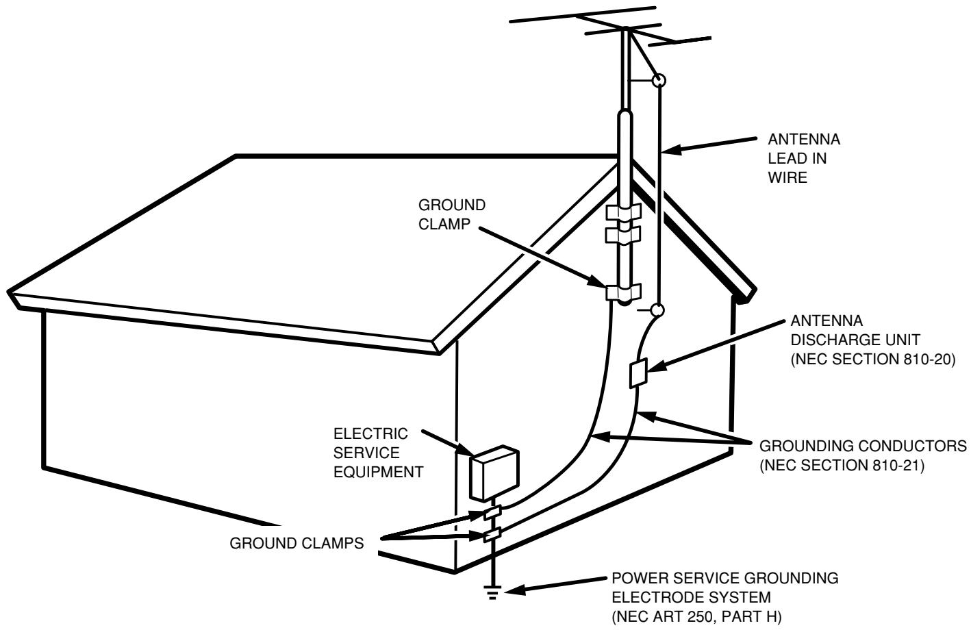
NEC - NATIONAL ELECTRICAL CODE
CONTENTS
FEATURES....1
BEFORE USE 2
PART NAMES AND FUNCTIONS ....4
FRONT PANEL 4
REAR PANEL ....5
REMOTE CONTROL UNIT 6
CONNECTIONS....8
CONNECTING THE ANTENNA TERMINALS 8
CONNECTING THE AMPLIFIER 9
OPERATION....10
LISTENING TO FM/AM 10
LISTENING TO XM SATELLITE RADIO ....14
SEARCH MODE ....17
OTHER OPERATION 19
SETTING THE CLOCK 19
TIMER PROGRAMS 20
LAST FUNCTION MEMORY ....22
INITIALIZATION OF THE MICROPROCESSOR ....22
TROUBLESHOOTING....23
SPECIFICATIONS & DIMENSIONAL DRAWINGS ....24
OTHERS 25
FEATURES
• XM Satellite Radio Ready
• High Performance D/A Converter
• 200 Channels, Group Presets
- Customizable Station Names
• Weekly Timer Program
- Sleep Timer
- Display Dimmer
- Timer-controlled AC outlet
• RS-232C Terminal for Custom Installation

READY
The XM name and related logos are registered trademarks of XM Satellite Radio Inc.
BEFORE USE
This section must be read before any connection is made to the mains supply.
■ EQUIPMENT MAINS WORKING SETTING
Your Marantz product has been prepared to comply with the household power and safety requirements that exist in your area.
ST7001 can be powered by 120V AC only.
COPYRIGHT
Recording and playback of any material may require consent. For further information refer to the following:
— Copyright Act 1956
— Dramatic and Musical Performers Act 1958
— Performers Protection Acts 1963 and 1972
— Any subsequent statutory enactments and orders
■ Do Not Locate in the Following Places
To ensure long-lasting use, do not locate the ST7001 where:
- Exposed to direct sunlight.
- Near to sources of heat such as heaters.
• Highly humid or poorly ventilated.
- Dusty.
- Subjected to mechanical vibrations.
- On wobbly, inclined or otherwise unstable surfaces
- Radiated heat is blocked such as in cramped audio racks.
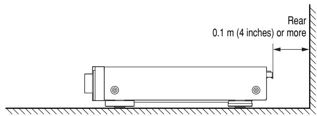
To ensure proper heat radiation, ensure the below clearance from walls and other equipment.
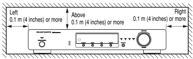
Noise or disturbance of the picture may be generated if this unit or any other electronic equipment using microprocessors is used near a tuner or TV.
If this happens, take the following steps:
• Install this unit as far as possible from the tuner or TV.
- Set the antenna wires from the tuner or TV away from this unit's mains cord and input/output connection cords.
- Noise or disturbance tends to occur particularly when using indoor antennas or 300 Ω/ohms feeder wires. We recommend using outdoor antennas and 75 Ω/ohms coaxial cables.
Note
For heat dispersal, do not install this equipment in a confined space such as a book case or similar unit.
■ Accessories Check
Before use, check the below accessories were included in the package.
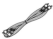
• Audio connecting cord x 1
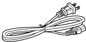
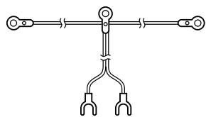
- Mains cord x 1
natural_image
Line drawing of a straight cord with two connectors and a power plug (no text or symbols)
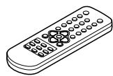
- Remote control unit (RC7001ST) x 1
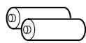
- Size "AAA" batteries x 2
- AM loop antenna x 1

- FM indoor antenna x 1
natural_image
Pure electrical circuit lines without any symbols
• FM antenna adaptor x 1
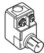
- Remote Control Connecting Cord x 1
- User Guide x 1
• Warranty Card for USA x 1
- Warranty Card for CANADA x 1
■ Loading batteries
Before using the supplied remote control unit for the first time, load the batteries in the remote control unit. The batteries provided are used to verify the operations of the remote control unit only.
- Take hold of the tab on the battery cover which is found on the back side of the remote control unit, and pull it up.
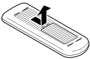
natural_image
Illustration of a handheld electronic device with a black checkmark on top (no text or symbols)
- Take load the two new size “AAA” batteries inside the battery compartment while taking care to align their polarities correctly with the polarity markings (⊕ with ⊕ and ⊖ with ⊖).
Size "AAA" (SUM-4) batteries x 2
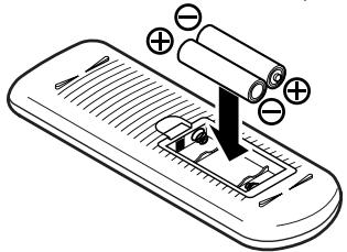
natural_image
Illustration of a smartphone with battery and resistor components, no text or symbols present
- Push the battery cover down in the direction of the arrow to close it.
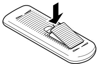
natural_image
Illustration of a handheld device with a handle and internal structure, no text or symbols present
Notes on batteries:
- If the battery fluid should leak, carefully wipe the fluid off the inside of the battery compartment and insert new batteries.
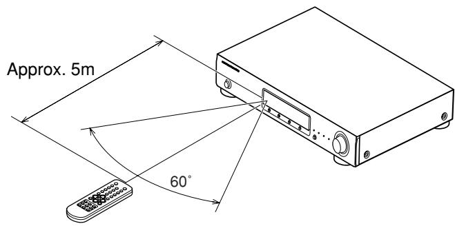
■ Operating range of the remote control unit
- Point the remote control unit at the remote sensor on the main unit as shown on the diagram.
- The remote control unit can be used from a straight distance of approximately 5 meters from the main unit, but this distance will be shorter if there are obstacles in the way or if the remote control unit is not pointed directly at the remote sensor.
- The remote control unit can be operated at a horizontal angle of up to 30 degrees with respect to the remote sensor.
Note
- It may be difficult to operate the remote control unit if the remote sensor is exposed to direct sunlight or strong artificial light.
- Do not press buttons on the main unit and remote control unit simultaneously. Doing so may result in malfunction.
- Neon signs or other devices emitting pulse-type noise nearby may result in malfunction, so keep the set as far away from such devices as possible.
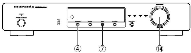
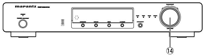
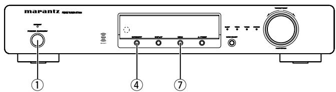
PART NAMES AND FUNCTIONS
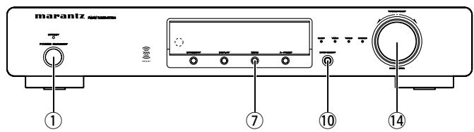
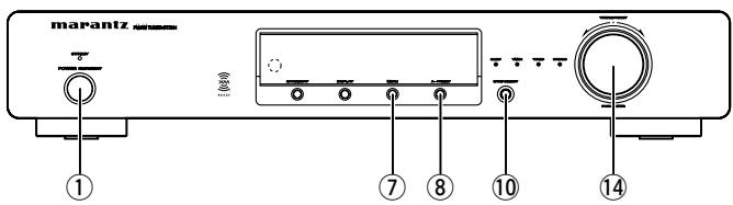
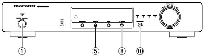
FRONT PANEL
For details on the functions of these parts, refer to the pages given in parenthesis.
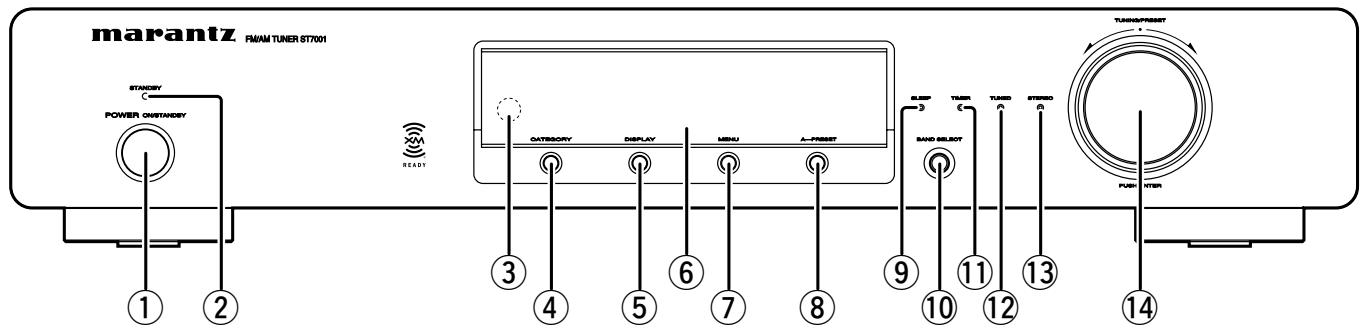
① Power ON/STANDBY switch
This is used to turn the unit's power ON and STANDBY. When it is pressed, the display lights and the power is turned on; when it is pressed again, the power is turned off and STANDBY indicator will be illuminated.
② STANDBY indicator
This indicator illuminates red when the unit's status is standby.
③ Remote control sensor
This sensor receives the infrared light transmitted from the wireless remote control unit.
For remote control, point the wireless remote control unit to the sensor.
Some of the functions can be operated with the remote control unit (RC7001ST).
This button to ENTER/EXIT XM Category search mode. Available only when the unit is in the XM Satellite Radio mode.
This button is used to switch XM information such as artist name/song title, category or signal status.
Available only when the unit in the XM Satelite Radio mode.
⑥ Display
This button to ENTER/EXIT menu mode.
The unit times out if no operation is performed for about 5 seconds after the menu mode is set.
This button is used for the auto preset memory feature which automatically searches for and sets radio stations.
⑨ SLEEP indicator
This indicator illuminates while the sleep timer is running. The display is automatically dimmed while the sleep timer is running.
This button is used to select XM, FM or AM.
⑪ TIMER indicator
This indicator illuminates while the timer program is ON.
Timer Program
When a recording device with an auto start recording function is connected (power on) to the AC outlet on the rear panel of this tuner, timer recording is can be controlled by the tuner's timer.
Note
- For setting procedures for recording device, see the instruction manual that came with the recording device.
- If the internal clock has not been set, set the time first before using the timer program. ( page 19)
⑫ TUNED indicator
This indicator illuminates when a station is properly tuned in.
⑬ STEREO indicator
This indicator illuminates when an FM station is being tuned into stereo condition.
⑭ TUNING/PRESET knob
This knob is used in conjunction with the MENU button, and is used to select and determine the operation mode. Also, this knob is used for the TUNING/PRESET search. In the tuning mode, the reception frequency is tuned up or down. Turning the control in the clockwise direction tunes the frequency up. Tuning the control in the counterclockwise direction tunes the reception frequency down.
In the preset mode, the selection of the preset channel is moved up or down. The auto tuning operation cannot be used when in this mode.
When entering station names, use this control to select the letters ( page 13).
Memo
- Whenever the Power ON/STANDBY switch is in the STANDBY position, the unit is still connected on AC line voltage.
Please be sure to unplug the cord when you leave home for, say, a vacation.
- Noise may be generated if a near-by television set is on during AM, FM or XM broadcasting reception. The tuner should be used as far away from a television as possible.
- Effective period of memory back-up is about a month under normal temperature.
REAR PANEL
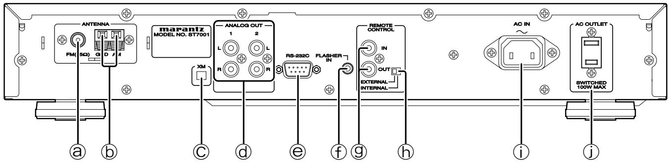
Ⓐ FM antenna terminal (75 ohms)
Connect an external FM antenna with a coaxial cable, or the supplied FM indoor antenna.
⑥ AM antenna and ground terminals
Connect the supplied AM loop antenna. Use the terminals marked "AM" and "GND". The supplied AM loop antenna will provide good AM reception in most areas. Position the loop antenna until you hear the best reception.
© XM terminal
See page 14 for connecting information.
d ANALOG OUT 1, 2 (analog output) connectors
The audio signals are output from these connectors.
e RS-232C
The RS-232C port is to be used in conjunction with an external controller to control the operation of the ST7001 by using an external device.
This terminal is to control the unit from another zone. Connect the control signal from a Keypad, etc.
⑨ REMOTE CONTROL IN and OUT connectors
Using the supplied remote control connecting cord, these connectors enable this unit to be connected to a Marantz component equipped with remote control connectors. These connections make it possible to control an entire system that centers on the amplifier or other such component.
h EXTERNAL/INTERNAL switch
Before the unit was shipped from the factory, this switch was set to INTERNAL to enable the remote sensor built into the unit to be used.
Before using the supplied connecting cord to make the connection between the unit and the remote control connectors on a Marantz equipment, set the switch to EXTERNAL.
Note
- Signals cannot be received from the remote control unit if the switch is kept at EXTERNAL when the unit is to be used on its own.
i AC INLET
Plug the supplied mains cord into this AC INLET and then into the power outlet on the wall.
ST7001 can be powered by 120V AC only.
j AC OUTLET
Connect the AC mains cord of components such as a MD or Tape Deck to this outlet. This SWITCHED outlet provides power only when the ST7001 is turned on.
Caution
- In order to avoid potential turn-off thumps, anything plugged into this outlet should be powered up before the ST7001 is turned on.
- The capacity of this AC outlet is 100W. Do not connect devices that consume electricity more than the capacity of this AC outlet.
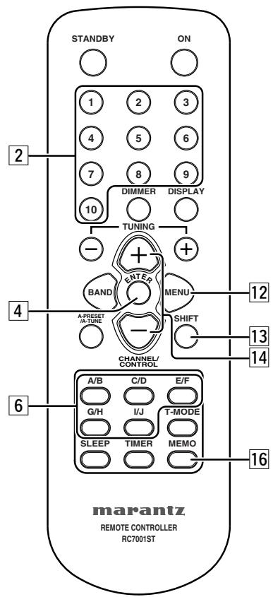
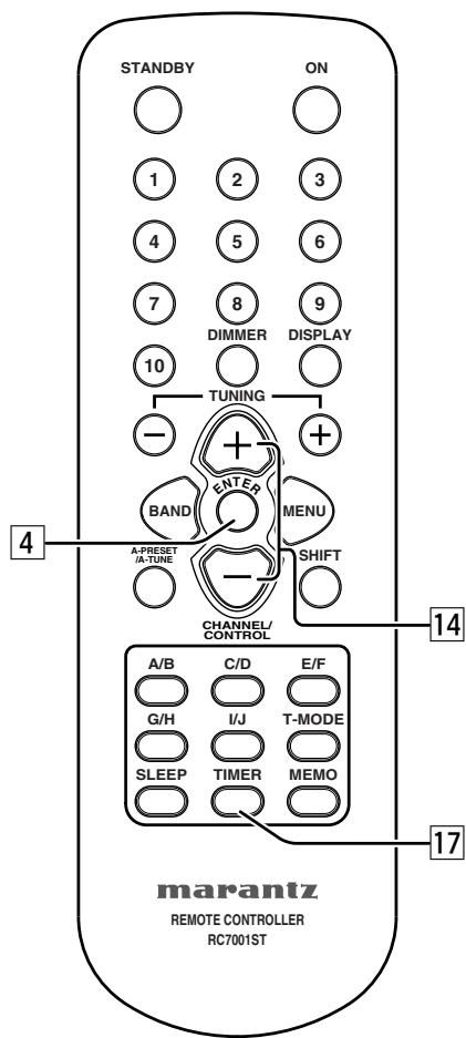
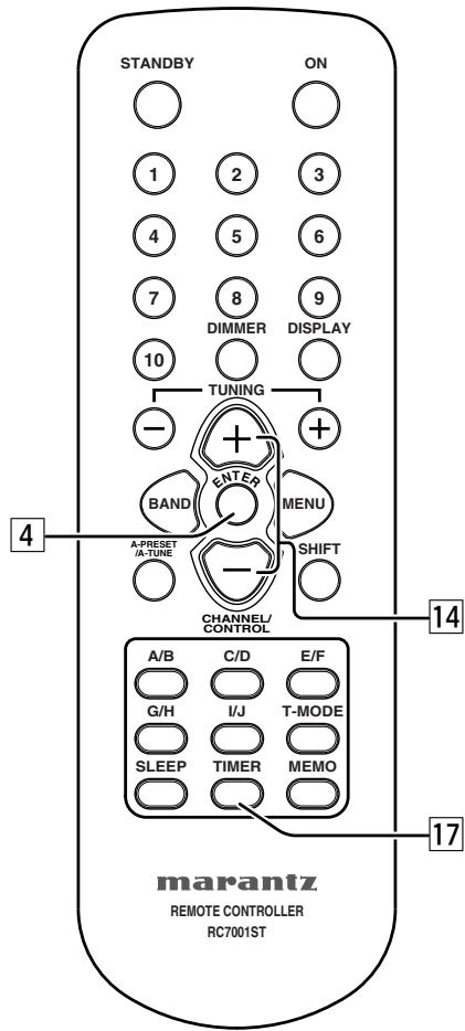
PART NAMES AND FUNCTIONS
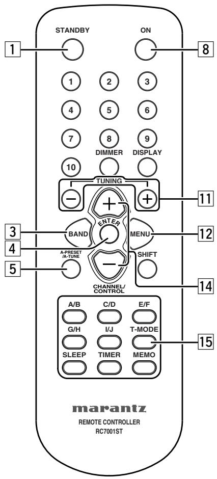
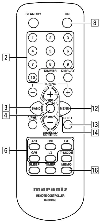
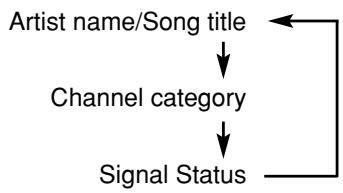
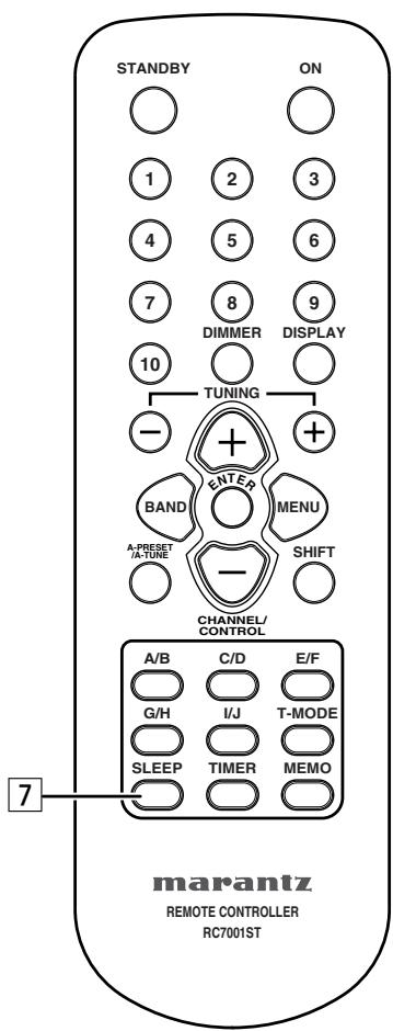
REMOTE CONTROL UNIT
For details on the functions of these parts, refer to the pages given in parenthesis ( page 10 \~ 22).
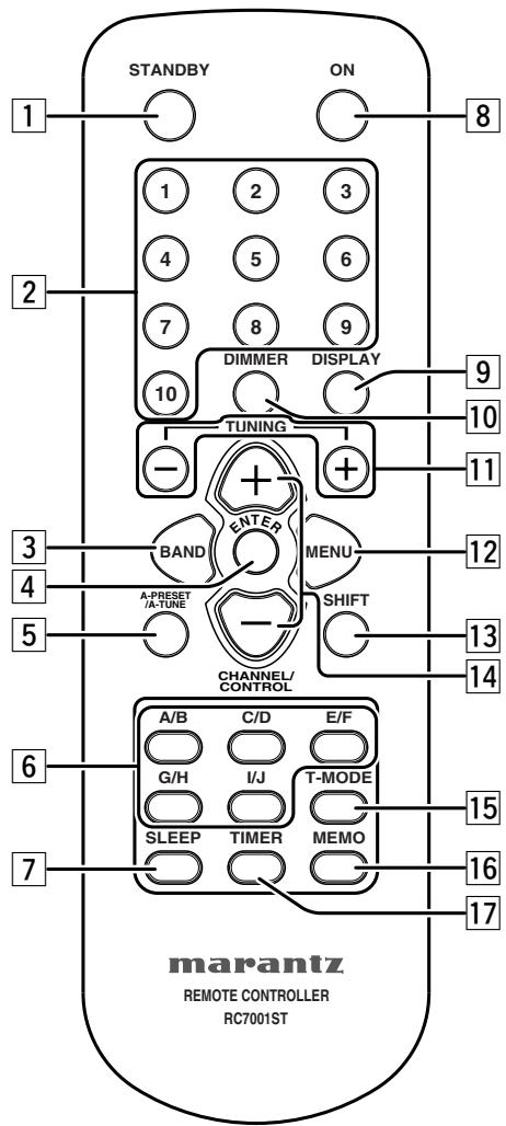
Press this button to switch from the operating mode to the standby mode.
Use these when presenting and recalling stations. Also use these with the SHIFT ,MEMORY GROUP button to use a total of 200 preset channels (FM/AM 100 , XM 100), A (1 \~ 10), B (1 \~ 10), ... J (1 \~ 10).
This button is used to select XM, FM or AM.
This button is used to set the menu.
When pressed in the FM mode, receivable FM/AM stations are automatically stored in the preset memory in order starting from preset channel A1.
Use these buttons to switch the preset channel's shift mode directly.
This button is used for setting the sleep timer. ( page 22)
Press this button to switch from the standby mode to the operating mode.
This button is used to switch XM information such as artist name/song title, category or signal status.
Available only when the unit in the XM Satellite Radio mode.
The display's brightness switches (in three levels) each time this button is pressed.
Use these to change the received frequency/XM channel to a higher frequency/XM channel (+) or a lower frequency/XM channel (−).
This button is used to enter/exit menu mode.
Use this button to select the memory groups, A (1 \~ 10), B (1 \~ 10), ... J (1 \~ 10).
This button is used to select radio presets or select stations and menu options.
Selects the stereo mode or mono mode when a FM stereo broadcast is received. ( page 10)
Frequencies and station names can be stored in the memory. When this button is pressed, the Preset channel number on the display flashes for 10 seconds. Use the SHIFT button and the Preset channel buttons during this time to designate the desired preset channel.
This button is used to enter the timer program mode. Clock setup mode can be entered by holding down this button for 3 seconds or more. Please refer to page 20 for TIMER program operation.
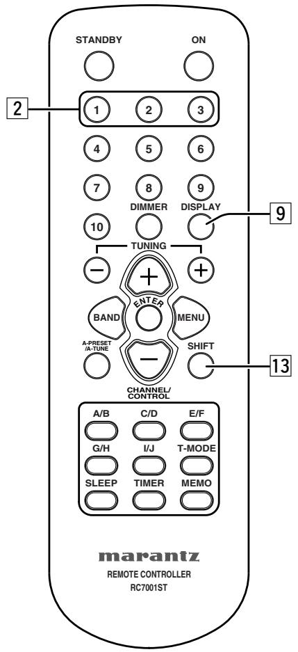
■ Remote control code setting
The remote control unit contains 3 sets of remote control codes, and it can be used to control up to 3 tuners in one location. To control a second or third tuner, select the remote control code as explained below. The selected tuner can be operated from the remote control.
- When the unit is shipped from the factory, the main unit and remote control are set to TUNER1.
1. TUNER2
To set the remote control to TUNER2, hold down both the SHIFT button 13 and 2 number button 2 on the remote control for at least five seconds.
TUNER3
To set the remote control to TUNER3, hold down both the SHIFT button 13 and 3 number button 2 on the remote control for at least five seconds.
- Also set the main unit's remote control setting to the same setting as the remote control. To change main unit's remote control setting, hold down both the SHIFT 13 and DISPLAY 9 buttons on the remote control; the remote control setting ("TUNER1", "TUNER2" or "TUNER3") will be displayed in the display window on the main unit and main unit setting will be changed same setting as remote control.
Note
- To set the remote control back to TUNER1, hold down both the SHIFT button 13 and 1 number button 2 on the remote control for at least five seconds.
- If the batteries in the remote control are replaced while the remote control is set to TUNER2 or TUNER3, the setting will revert to TUNER1.
- If the main unit is unplugged the mains cord, the remote control setting will revert to TUNER1.
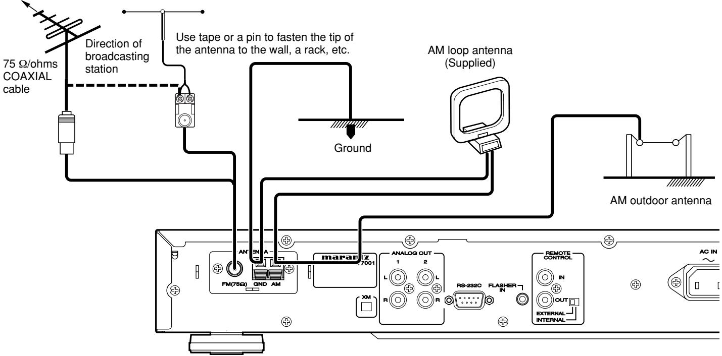
CONNECTIONS
CONNECTING THE ANTENNA TERMINALS
FM outdoor antenna FM indoor antenna (Supplied)
■ AM loop antenna assembly
①
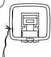
Remove the vinyl tie and take out the connection line.
②
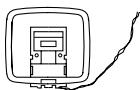
Connect to the AM antenna terminals.
③
Bend in the reverse direction.
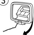
a. With the antenna on top any stable surface.
④
b. With the antenna attached to the wall.
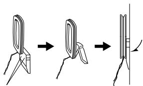
Installation hole Mount on the wall, etc.
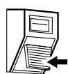
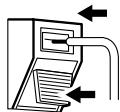
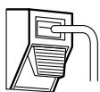
■ Connection of AM antennas
-
Push the lever.
-
Insert the conductor.
-
Return the lever.


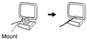
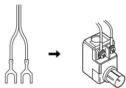
■ Connecting the antenna wire to the antenna adaptor
Loosen the screws and attach the wire terminals, then tighten the screws with a screwdriver.
natural_image
Diagram showing a fork-shaped connector transforming into a mechanical device (no text or symbols present)
Notes
Connecting an FM outdoor antenna
- Keep the antenna away from noise sources (neon signs, busy roads, etc.).
- Do not put the antenna close to power lines. Keep it well away from power lines, transformers, etc.
- To avoid the risk of lightning and electrical shock, grounding is necessary.
Connecting an AM outdoor antenna
An outdoor antenna will be more effective if it is stretched horizontally above a window or outside.
- Do not remove the AM loop antenna.
- To avoid the risk of lightning and electrical shock, grounding is necessary.
CONNECTING THE AMPLIFIER
Note
- Do not plug in the mains cord until all connections have been completed.
- When making connections, also refer to the operating instructions of the other components.
- Be sure to connect the left and right channels properly (left with left, right with right).
- Note that binding pin-plug cords together with mains cords or placing them near a power transformer will result in generating hum or other noise.
■ Connecting the analog output connector
Use the audio connecting cord to connect the unit with a stereo amplifier or AV amplifier. Do not connect the unit to the PHONO input connectors on the amplifier.
When making the connections, insert the plugs securely into the connectors. Failure to insert the plugs securely may result in noise.
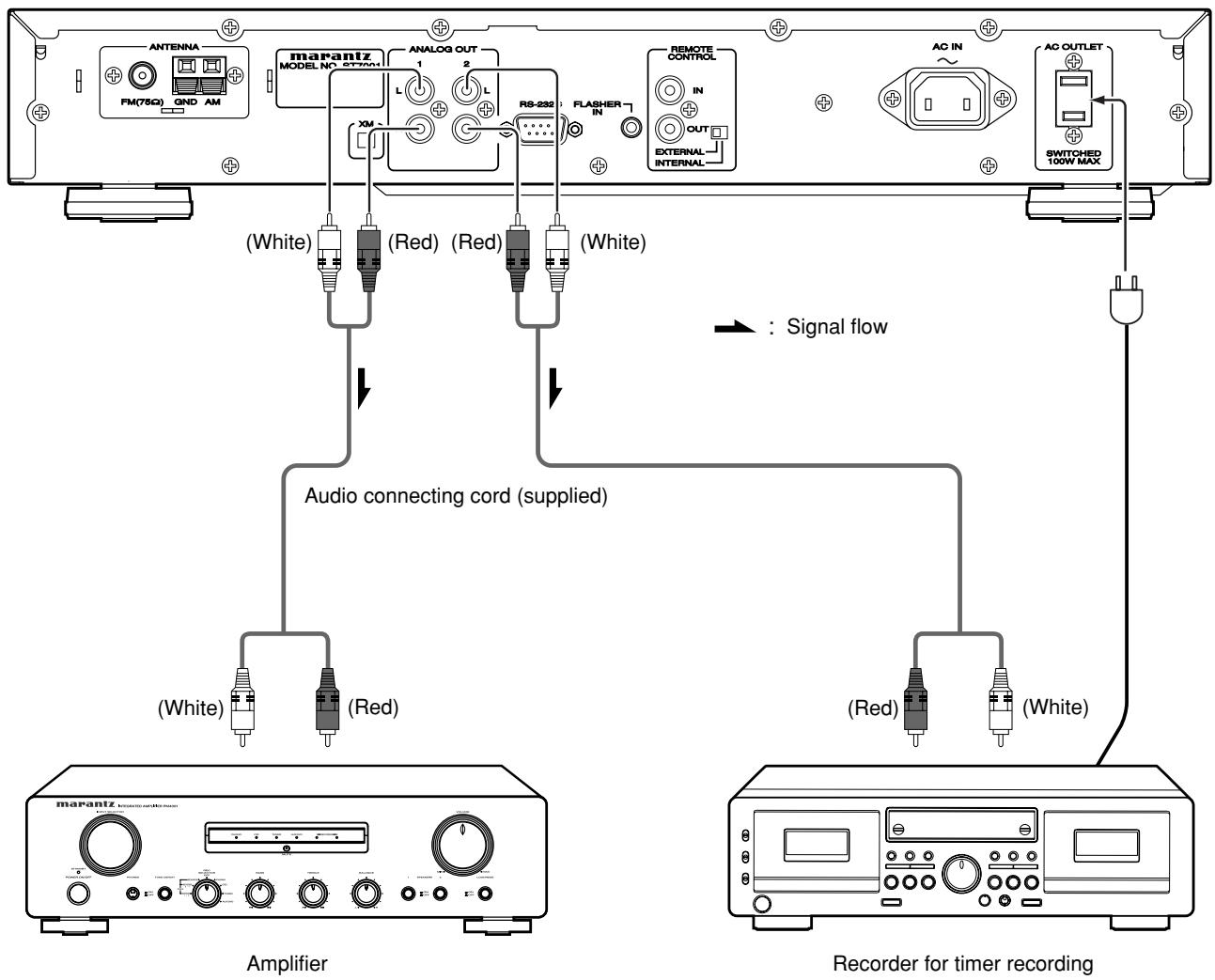
flowchart
graph TD
    A["Amplifier"] --> B["Audio connecting cord (supplied)"]
    B --> C["Recorder for timer recording"]
    subgraph Amplifier
        D["Antenna FM(75Ω) GND AM"]
        E["marantz MODEL NO SYSTEM1"]
        F["(White)"]
        G["(Red)"]
        H["(Red)"]
        I["(White)"]
        J["(White)"]
        K["(Red)"]
        L["(White)"]
        M["(Red)"]
        N["(White)"]
    end
    subgraph Recorder
        O["AC IN"]
        P["AC OUTLET"]
        Q["SWITCHED 100W MAX"]
    end
    style Amplifier fill:#f9f,stroke:#333
    style Recorder fill:#bbf,stroke:#333
LISTENING TO FM/AM
FM Auto preset memory
- Press the POWER ON/STANDBY switch ① or ON button ⑧ to turn on the power.
- Watching the display, press the BAND SELECT button ⑩ or BAND button ③ to select the FM band.
F H
- Press the A-PRESET button ⑧ or A-PRESET/A-TUNE button 5.
AUTO PRESET
- Press the TUNING/PRESET knob ⑭ or ENTER button ④.
- The unit automatically begins searching for FM broadcast stations.
AUTO PRESET
- When the first FM broadcast station is found, that station is stored in the preset memory at channel A1.
- Subsequent stations are automatically stored in order at preset channels A1 to A10, B1 to B10, C1 to C10, D1 to D10, E1 to E10, F1 to F10, G1 to G10, H1 to H10, I1 to I10 and J1 to J10 for a maximum of 100 stations.
- After presetting all of the FM broadcast stations, the timer starts presetting AM broadcast stations.
- Channel A1 is tuned in after the auto preset memory operation is completed.
Note
- If an FM station cannot be preset automatically due to poor reception, use the “Manual tuning” operation to tune in the station, then preset it using the manual “Preset memory” operation. ( page 15)
- To interrupt this function, press the POWER ON/STANDBY switch ① or STANDBY button ①.
DEFAULT VALUE
| Auto tuner presets |
| A1 ~ A10 | 87.5 / 89.1 / 98.1 / 108.0 / 92.75 / 92.75 / 92.75 / 92.75 / 92.75 / 92.75 MHz |
| B1 ~ B10 | 520 / 610 / 1050 / 1500 / 1700 kHz92.75 / 92.75 / 92.75 / 92.75 / 92.75 MHz |
| C1 ~ C10 | 92.75 MHz |
| D1 ~ D10 | 92.75 MHz |
| E1 ~ E10 | 92.75 MHz |
| F1 ~ F10 | 92.75 MHz |
| G1 ~ G10 | 92.75 MHz |
| H1 ~ H10 | 92.75 MHz |
| I1 ~ I10 | 92.75 MHz |
| J1 ~ J10 | 92.75 MHz |
■ Auto tuning (FM/AM)
- Press the POWER ON/STANDBY switch ① or ON button ⑧ to turn on the power.
- Watching the display, press the BAND SELECT button ⑩ or BAND button ③ to select the desired band (AM or FM).
F M
-
Press the MENU button ⑦ or ⑫ to select menu.
-
-
-
-
-
-
-
-
-
-
-
-
-
-
-
-
-
-
-
-
-
-
-
-
-
-
-
-
-
-
-
-
-
-
-
-
-
-
-
-
-
-
-
-
-
-
-
-
-
-
-
-
-
-
-
-
-
-
-
-
-
-
-
-
-
-
-
-
-
-
-
-
-
-
-
-
-
-
-
-
-
-
-
-
-
-
-
-
-
-
-
-
-
-
-
-
-
- 99.
-
Press the TUNING/PRESET knob ⑭ or ENTER button ④ to set search mode.
- Either turn the TUNING/PRESET knob ⑭ or press the CHANNEL/CONTROL button ⑭ to select "Auto".
[1] [2] [3] [4] [5] [6] [7] [8] [9] [10] [11] [12] [13] [14] [15] [16] [17] [18] [19] [20]
- Press the TUNING/PRESET knob ⑭ or ENTER button ④ to set the auto tuning mode.
F107.95MHz F100
H
- Either turn the TUNING/PRESET knob ⑭ or press the TUNING button ⑪.
- Automatic searching begins, then stops when a station tuned in.
Note
- When in the auto tuning mode on the FM band, the "STEREO" indicator lights on the panel when the stereo broadcast is tuned in. At open frequencies, the noise is muted and the "TUNED" and "STEREO" indicators tuned off.
- If the signal is weak, if may be difficult to tune into the station in stereo. In such a case, press the T-MODE button 15 on the remote control. FM stereo broadcasts are received in monaural and the stereo indicator is not illuminated. To return to stereo mode, press the T-MODE button 15 on the remote control again.
- If tuning does not stop at the desired station. Use “Manual tuning” operation.
■ Manual tuning (FM/AM)
- Press the POWER ON/STANDBY switch ① or ON button ⑧ to turn on the power.
- Watching the display, press the BAND SELECT button ⑩ or BAND button ③ to select the desired band (AM or FM).
- Press the MENU button ⑦ or ⑫ to select menu.
- Press the TUNING/PRESET knob ⑭ or ENTER button ④ to set search mode.
- Either turn the TUNING/PRESET knob 14 or press the CHANNEL/CONTROL button 14 to select "Manual".
The image contains no discernible text or symbols. The characters '***' are likely from the visual content, but they are not clearly represented as text. Therefore, the correct OCR output is an empty string.
- Press the TUNING/PRESET knob ⑭ or ENTER button ④ to set the manual tuning mode.
F1007.5.11
- Either turn the TUNING/PRESET knob ⑭ or press the TUNING button ⑪ to tune in the desired station.
- The frequency changes continuously when the TUNING button 11 on the remote control unit is held in.
■ Preset stations (FM/AM)
- Use the "Auto tuning" or "Manual tuning" operation to tune in the station to be preset in the memory.
- Press the MENU button ⑦ or ⑫ to select menu.
- Either turn the TUNING/PRESET knob ⑭ or press the CHANNEL/CONTROL button ⑭ to select "Memory".
PLENNY
- Press the TUNING/PRESET knob ⑭, or ENTER button ④ to set the preset mode and make the preset channel number flash.
AM 1010kHz AUTO
- Steps 1 to 4 can be skipped when using the MEMO 16 button.
When this button is pressed, the preset memory standby mode is set, regardless of the menu setting at that time.
- While the preset channel number is flashing, either press the SHIFT button 13 to select the desired memory group (A to J) or press a MEMORY GROUP (A to J) button 6.
- While the preset channel number is flashing, either turn the TUNING/PRESET knob ⑭, press the CHANNEL/CONTROL ⑭ or Preset channel button ② to select the desired preset channel (1 to 10).
- While the preset channel number is flashing, either press the TUNING/PRESET knob ⑭ or MEMO button ⑯ to store the station in the preset memory.
- To preset other channels, repeat steps 2 to 6.
- A total of 100 broadcast stations can be preset — 10 stations (channels 1 to 10) in each of groups A to J.
■ Recalling preset stations (FM/AM)
- Press the POWER ON/STANDBY switch ① or ON button ⑧ to turn on the power.
- Watching the display, press the BAND SELECT button ⑩ or BAND button ③ to select the desired band (AM or FM).
- Press the MENU button ⑦ or ⑫ to select menu.
- Steps 2 to 6 can be skipped when using the CHANNEL/CONTROL 14, SHIFT 13, MEMORY GROUP (A to J) 6 and Preset channel 2 buttons.
The preset mode is set when any of these buttons is pressed, regardless of the menu setting at that time.
■ Registering station names (FM/AM only)
- Use the procedure described at "Auto tuning", "Manual tuning" or "Recalling preset stations" to tune in the desired frequency.
Example: To register "MARANTZ" as the FM station name at preset channel "A2".
- Press the MENU button ⑦ or ⑫ to select menu.
-
While “_” is flashing, either turn the TUNING/PRESET knob ⑭ or press the CHANNEL/CONTROL button ⑭ to display “M”.
-
The “_” moves to the right when the TUNING/PRESET knob ⑭ or ENTER button ④ is pressed. Use the same procedure to display “A”, “R”, “A”, “N”, “T”, and “Z”, in that order.
“……”
- Press the TUNING/PRESET knob ⑭ or ENTER button ④ for at least 2 seconds.
- The station name is set.
- Then “A2” blinks, either press the TUNING/PRESET knob 14 or MEMO button 16 to store the station name in the preset memory.
- This procedure can be used to registered station names with up to 8 digits for up to 100 AM/FM stations at random.
- The 63 characters below can be selected.
ABCDEFGHIJKLMNOPQRSTUVWXYZ 0123456789[\]^_!#“$%&’() * +,-./:;<=>? (space)
LISTENING TO XM SATELLITE RADIO
XM Radio Overview
Introducing XM Satellite Radio
There's a world of audio listening pleasure beyond AM and FM. XM Satellite Radio. Select from over 150 channels of music, news, sports, comedy, talk, and entertainment. Coast-to-coast coverage. Digital quality sound. With all music channels 100% commercial free.
Questions?: Visit www.xmradio.com.
How to Subscribe
Listeners can subscribe by visiting XM on the Web at www.xmradio.com or by calling XM's Listener Care at (800) 967-2346. Customers should have their Radio ID and credit card ready. The Radio ID can be found by selecting channel 0 on the radio. (Checking the XM signal strength and Radio ID")
A Warning Against Reverse Engineering
It is prohibited to copy, decompile, disassemble, reverse engineer, or manipulate any technology incorporated in receivers compatible with the XM Satellite Radio system.
Furthermore, the AMBE® voice compression software included in this product is protected by intellectual property rights including patent rights, copyrights, and trade secrets of Digital Voice Systems, Inc. The user of this or any other software contained in an XM Radio is explicitly prohibited from attempting to copy, decompile, reverse engineer, or disassemble the object code, or in any other way convert the object code into human-readable form. The software is licensed solely for use within this product.
Hardware and required basic monthly subscription sold separately. Premium Channel available at additional monthly cost. Installation costs and other fees and taxes, including a one-time activation fee may apply. Subscription fee is consumer only. All fees and programming subject to change. Subscriptions subject to Customer Agreement available at xmradio.com. Only available in the 48 contiguous United States. ©2005 XM Satellite Radio Inc. All rights reserved. All other trademarks are the property of their respective owners.
Connecting the XM Connect -and-Play Antenna
- Plug the XM Connect-and-Play antenna into XM terminal on the rear panel.
- Position the XM Connect-and-Play antenna near a south-facing window to receive the best signal. When making connections, also refer to the operating instructions of the XM Connect-and-Play antenna.
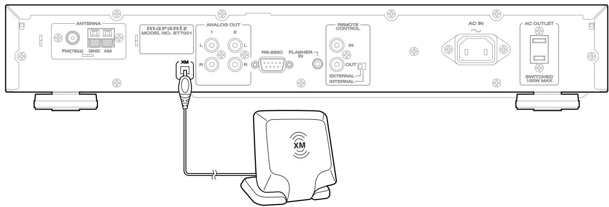
Note
- Keep the power supply cord unplugged until the XM Connect-and-Play antenna connection have been completed.
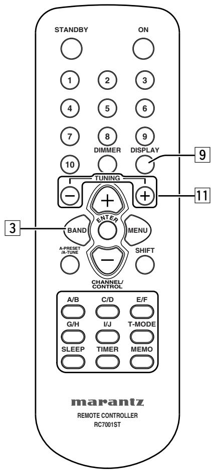
■ Checking the XM signal strength and Radio ID
- Press the POWER ON/STANDBY switch ① or ON button ⑧ to turn on the power.
- Watching the display, press the BAND SELECT button ⑩ or BAND button 3 to select the XM mode.
X M
- Press the DISPLAY button ⑤ or ⑨ twice. Signal status is displayed.
XM940 DeepTrks
STRONG
- The display changes as shown below according to the receiving condition.
| Display | Condition |
| STRONG | Signal strength is good |
| MARGINAL | Signal strength is marginal |
| WEAK | Signal strength is poor |
| NO | Loss of the signal |
-
Adjust the antenna location until "SIGNAL:STRONG" is displayed.
-
Press the TUNING - button 11 to select channel 0 (XM000).
• The Radio ID is displayed.
XINGG RADIO ID
[Non-Text]

Note
- If “CHECK ANTENNA” appears in the front panel display, the XM Connect-and-Play antenna may not be connected to the XM terminal on the rear panel of this unit properly.
- You can not select channel "0" if the All channel search mode is not selected.
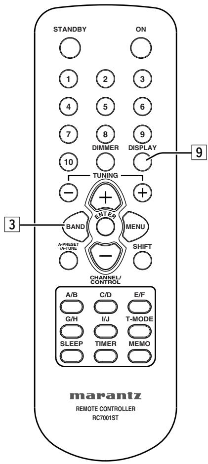
OPERATION
You can display XM information (such as artist name, song title, category or signal status) for the channel currently selected in the front panel display.
- Watching the display, press the BAND SELECT button ⑩ or BAND button 3 to select the XM mode.
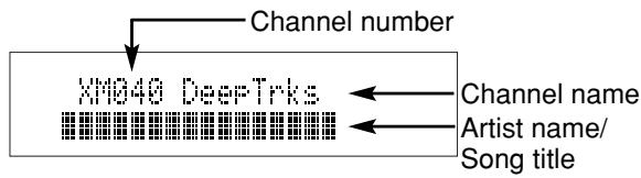
- Press the DISPLAY button ⑤ or ⑨ repeatedly to toggle between the following channel information display modes.
flowchart
graph TD
    A["Artist name/Song title"] --> B["Channel category"]
    B --> C["Signal Status"]
    C --> A
When the channel Artist name/Song title is displayed:
Xin040 DeepTrks
Pink Flood / Mon
When the channel category is displayed:
XM040 DeepTrks
Rock
When the signal status is displayed:
XIM049 DeepTrks
STRONG
Note
- The front panel display can indicate up to 16 alphanumeric characters at once. If the information contains more than 16 characters, the information scrolls from right to left.
- If the information contains a character that cannot be recognized by that unit, the character will be displayed with “” (space).

SEARCH MODE
You can search for the channel you want to listen to using one of three search modes. You can also enter the number directly to select the desired channel (For details, see "Direct Number Access mode" on page 18).
All Channel search mode
- Press the MENU ⑦ or ⑫ button to select menu.
P1. P2. P3. P4. P5. P6. P7. P8. P9. P10. P11. P12. P13. P14. P15. P16. P17. P18. P19. P20. P21. P22. P23. P24. P25. P26. P27. P28. P29. P30. P31. P32. P33. P34. P35. P36. P37. P38. P39. P40. P41. P42. P43. P44. P45. P46. P47. P48. P49. P50.
- Press the TUNING/PRESET knob ⑭ or ENTER button ④ to set the search mode.
- Either turn the TUNING/PRESET knob ⑭ or press the CHANNEL/CONTROL button ⑭ to select "Search Mode All CH Search".
- To search a channel within all channels, either turn the TUNING/PRESET knob 14 or press the CHANNEL/CONTROL button 14 repeatedly.
Preset search mode
Prior to selecting a preset channel in the Preset Search mode, You should preset XM Satellite Radio channels. For details, see “preset channels (XM)” on page 18.
- Press the MENU button ⑦ or ⑫ to select menu.
[1] [2] [3] [4] [5] [6] [7] [8] [9] [10] [11] [12] [13] [14] [15] [16] [17] [18] [19] [20]
- Press the TUNING/PRESET knob ⑭ or ENTER button ④ to set the search mode.
- Either turn the TUNING/PRESET knob ⑭ or press the CHANNEL/CONTROL button ⑮ to select "Search Mode Preset".
1
2
3
4
5
6
7
8
9
10
11
12
13
14
15
16
17
18
19
20
21
22
23
24
25
26
27
28
29
30
31
32
33
34
35
36
37
38
39
40
41
42
43
44
45
46
47
48
49
50
51
52
53
54
55
56
57
58
59
60
61
62
63
64
65
66
67
68
69
70
71
72
73
74
75
76
77
78
79
80
81
82
83
84
85
86
87
88
89
90
91
92
93
94
95
96
97
98
99
100
- Press the TUNING/PRESET knob ⑭ or ENTER button ④ to display the first channel at Preset.
XM040 DeepTrks
A10
5 ^-1 .Watching the display, turn the TUNING/ PRESET knob ⑭, or press the CHANNEL/CONTROL button ⑭ to select the desired preset channel.
5 ^2 .Press the SHIFT button 13 and select the desired memory group (A to J) or press the MEMORY GROUP (A to J) button 6.
5 ^-3 . Press the Preset channel button 2 to select the desired preset channel (1 to 10).
Note
- Steps 2 to 6 can be skipped when using the CHANNEL/CONTROL 14, SHIFT 13 and MEMORY GROUP (A to J) 6 buttons.
The preset mode is set when any of these buttons is pressed, regardless of the menu setting at that time.
■ Category search mode
- Press the MENU ⑦ or ⑫ button to select menu.
When this button is pressed, the category search mode is set, regardless of the menu setting at that time.
- To change the category, either turn the TUNING/PRESET knob 14 or press the CHANNEL/CONTROL button 14 repeatedly.
- Press the TUNING/PRESET knob ⑭ or ENTER button ④ to select the category.
XIN840 DeepTrks
CAT : Rock
- To search a channel within the selected category, either turn the TUNING/PRESET knob 14 or press the CHANNEL/CONTROL button 14 repeatedly.
■ Direct Number Access mode
You can not call channel if the preset channel search mode is selected.
- Press the Preset channel buttons 2 to enter the desired channel number.
For example, to enter the number 13ch press the Preset channel buttons 2 as shown below.

The display changes as follows.
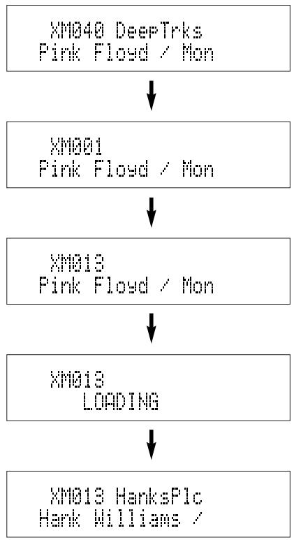
flowchart
graph TD
    A["XMQ40 DeepTrks\nPink Floyd / Mon"] --> B["XMQ01\nPink Floyd / Mon"]
    B --> C["XMQ13\nPink Floyd / Mon"]
    C --> D["XMQ13\nLOADING"]
    D --> E["XMQ13 HanksPlc\nHank Williams /"]
- Press the ENTER button 4 to tune to the channel.
Note
- If no button is pressed within five seconds after entering one-digit or two-digit number, the unit automatically confirms the entered channel number.
- Pressing a button other than Preset channel buttons 2 or ENTER button 4 cancels the direct number access procedure.
■ Preset channels (XM)
- Use the "All channel search mode" or "Category search mode" or "Direct Number Access mode" to tune in the channel to be preset in the memory.
- Press the MENU button ⑦ or ⑫ to select menu.
- Either turn the TUNING/PRESET knob ⑭ or press the CHANNEL/CONTROL button ⑭ to select "Memory".
The image contains pixelated, abstract symbols and no textual content. Therefore, the correct OCR output is an empty string.
- Press the TUNING/PRESET knob ⑭, or ENTER button ④ to set the preset mode and make the preset channel number flash.

- Steps 1 to 4 can be skipped when using the MEMO 16 button.
When this button is pressed, the preset memory standby mode is set, regardless of the menu setting at that time.
- While the preset channel number is flashing, either press the SHIFT button 13 to select the desired memory group (A to J) or press a MEMORY GROUP (A to J) button 6.
- While the preset channel number is flashing, either turn the TUNING/PRESET knob ⑭, press the CHANNEL/CONTROL ⑭ or Preset channel button ② to select the desired preset channel (1 to 10).
- While the preset channel number is flashing, either press the TUNING/PRESET knob 14 or MEMO button 16 to store the channel in the preset memory.
- To preset other channels, repeat steps 2 to 6.
- A total of 100 XM Satellite Radio Channels can be preset — 10 channels (channels 1 to 10) in each of groups A to J.
SETTING THE CLOCK
■ Present time setting
- To operate the timer program, you must set the present time. The clock time can be set 12-hour or 24-hour system. The clock displays “SUNDAY” “12H SYSTEM” “0:00AM” at initial.
- Press and hold down the TIMER button 17 until the "CLOCK 0:00AM" is displayed.
CLOCK
0:00AM
- Press the TUNING/PRESET knob ⑭ or ENTER button ④, the day of the week flashes.
CLOCK SETUP
SUNDAY
-
Either turn the TUNING/PRESET knob ⑭ or press the CHANNEL/CONTROL button ⑭ to select a day.
-
Press the TUNING/PRESET knob ⑭ or ENTER button ④, "12H SYSTEM" is flashes.
CLOCK SETUP
12H SYSTEM
If you want to select 24H SYSTEM, either turn the TUNING/PRESET knob ⑭ or press the CHANNEL/CONTROL button ⑭.
- Press the TUNING/PRESET knob ⑭ or ENTER button ④ to set the desired system. The hour digit flashes.
CLOCK SETUP
8:00AM
-
Either turn the TUNING/PRESET knob ⑭ or press the CHANNEL/CONTROL button ⑭ to set the hours and press the TUNING/PRESET knob ⑭ or ENTER button ④. The minute digit flashes.
-
Either turn the TUNING/PRESET knob 14 or press the CHANNEL/CONTROL button 14 to set the minutes, and press the TUNING/PRESET knob 14 or ENTER button 4. The display flashes.
CLOCK
0:00AM
- Press the TUNING/PRESET knob ⑭ or ENTER button ④ to confirm the actual time. The clock now starts.
- In the event of a power failure or when the AC mains cord is disconnected. You must reset the clock.
■ Displaying present time
- A present time can be displayed for 5 seconds by holding down the TIMER button 17 more than 3 seconds.
CLOCK
5:00PM

TIMER PROGRAMS
About the Timer Programs
- This unit has three timer programs so that you can turn it on and off automatically at certain times and on certain days of the week.
- Timer programs can be set for single operation (Once) or everyweek operation (Everyweek) or everyday operation (Everyday) or the days of the week operation (Weekday).
Timer Program Examples
- The following examples highlight some of the ways in which you can use the timer programs.
Example 1: To wake up to your favorite radio station every morning, set as follows:
TIMER PROGRAM 1 SET → FM/AM → A1 FM 87.50MHz → EVERYDAY → ON TIME= 7:00AM → OFF TIME= 7:30AM (If you want a radio alarm only on weekdays, select “WEEKDAY” instead of “EVERYDAY” and specify “MON-FRI”.)
Example 2: To listen a radio program on only this Sunday, set as follows:
TIMER PROGRAM 2 SET → FM/AM → B1 AM520kHz
→ ONCE → SUNDAY → ON TIME= 9:00PM → OFF
TIME=10:00PM
Timer Program Overlap
- If two or three timer programs are set to the same ON TIME, the timer program with the lowest number has priority.
For example, if Timer program 1 and Timer program 2 are both set to an ON TIME of 7:00AM, Timer program 1 has priority and Timer program 2 is ignored.
Timer program 1: 7:00AM - 1:00PM
(This timer has priority)
Timer program 2: 7:00AM - 0:30PM
If the setting of the two timer program overlaps, the earlier timer has priority.
Timer program 1: 9:00AM - 10:00AM
Timer program 2: 8:00AM - 10:00AM
(Timer program 2 has priority)
Timer Program Setting
- You must set the clock time before you set the timer programs.
- You need to store preset stations before you set the timer programs.
- Press the TIMER button 17, "TIMER PROGRAM 1" is displayed.
TIMER PROGRAM 1
- The display changes as follows each time the TUNING/PRESET knob ⑭ is turned or the CHANNEL/CONTROL button ⑮ is pressed.
TIMER PROGRAM 1 ← TIMER PROGRAM 2
TIMER PROGRAM 3 ←
-
Press the TUNING/PRESET knob ⑭ or ENTER button ④ to select timer program number.
-
The display indicate "TIMER PROGRAM x SET".
TIMER PROGRAM 1
SET
Either turn the TUNING/PRESET knob ⑭ or press the CHANNEL/CONTROL button ⑮, the display changes as follows.
TIMER PROGRAM x SET ← TIMER PROGRAM x CONFIRM
TIMER PROGRAM x OFF ← TIMER PROGRAM x ON
- If timer program is already available, to select “TIMER PROGRAM x CONFIRM” to scroll the timer setting contents.
- If timer program is already available, to select “TIMER PROGRAM x ON” to activate the timer.
-
To select "TIMER PROGRAM x OFF" to turn off the timer program.
-
Press the TUNING/PRESET knob ⑭ or ENTER button ④ to select "TIMER PROGRAM x SET".
-
The display indicate "TIMER PROGRAM x FM/AM". Either turn the TUNING/PRESET knob ⑭ or press the CHANNEL/CONTROL button ⑭, the display changes "TIMER PROGRAM x FM/AM" or "TIMER PROGRAM x XM".
TIMER PROGRAM 1
FM/AM
-
Press the TUNING/PRESET knob ⑭ or ENTER button ④ to select "FM/AM" or "XM".
-
Either turn the TUNING/PRESET knob 14 or press the CHANNEL/CONTROL button 14 to select Preset station to be programmed.
TIMER PROGRAM 1
AI FM 87.50MHz
- Select the Operation method.
TIMER PROGRAM 1
ONCE
Either turn the TUNING/PRESET knob ⑭ or press the CHANNEL/CONTROL button ⑭ to select operation method “ONCE”, “EVERYWEEK”, “EVERYDAY” or “WEEKDAY”.
② Press the TUNING/PRESET knob ⑭ or ENTER button ④ to decide the operation.
When you select "ONCE" or "EVERYWEEK", you can select the day of the week by turning the TUNING/PRESET knob ⑭ or pressing the CHANNEL/CONTROL button ⑮.
When you select "WEEKDAY", use the TUNING/PRESET knob ⑭ or pressing the CHANNEL/CONTROL button ⑭ to select the first day, and then press the TUNING/PRESET knob ⑭ or ENTER button ④.
Use the TUNING/PRESET knob ⑭ or pressing the CHANNEL/CONTROL button ⑯ to select the last day. Then press the TUNING/PRESET knob ⑭ or ENTER button ④.
- Set the On time.
TIMER PROGRAM 1
ON TIME= 0:00AM
Either turn the TUNING/PRESET knob ⑭ or press the CHANNEL/CONTROL button ⑭ to adjust the hour for the On time and press the TUNING/PRESET knob ⑭ or ENTER button ④.
② Either turn the TUNING/PRESET knob ⑭ or press the CHANNEL/CONTROL button ⑭ to adjust the minutes for the On time and press the TUNING/PRESET knob ⑭ or ENTER button ④.
- Set the Off time.
TIMER PROGRAM 1
OFF TIME=0:00AM
Either turn the TUNING/PRESET knob ⑭ or press the CHANNEL/CONTROL button ⑭ to adjust the hour for the Off time and press the TUNING/PRESET knob ⑭ or ENTER button ④.
② Either turn the TUNING/PRESET knob ⑭ or press the CHANNEL/CONTROL button ⑮ to adjust the minutes for the Off time.
- Set the timer program.
① Press the TUNING/PRESET knob ⑭ or ENTER button ④ to decide the timer program setting. Timer indicator lights up and setting contents are scrolled.
Note
- Timer program can activate regardless of power on or standby mode.
- When timer program is finished, the unit goes to standby mode.
- You can cancel the Timer program setting procedure at any time by pressing the TIMER button 17.
■ Confirm and change timer program
- You can check and change the timer program setting as follows.
- Press the TIMER button 17.
- Either turn the TUNING/PRESET knob ⑭ or press the CHANNEL/CONTROL button ⑭ to select timer program number.
- You can change the displayed contents with the TUNING/PRESET knob 14 or CHANNEL/CONTROL 14 and ENTER buttons 4 if necessary.
Note
- Timer program is not changed if you quit confirming halfway through a procedure.
■ Timer program off
- Press the TIMER button 17 , “TIMER PROGRAM 1” is displayed.
- Either turn the TUNING/PRESET knob ⑭ or press the CHANNEL/CONTROL button ⑭ to select timer program number.
- Press the TUNING/PRESET knob ⑭ or ENTER button ④, "TIMER PROGRAM x SET" is displayed.
- Either turn the TUNING/PRESET knob ⑭ or press the CHANNEL/CONTROL button ⑭ to select "TIMER PROGRAM x OFF".
TIMER PROGRAM X
OFF
- Press the TUNING/PRESET knob ⑭ or ENTER button ④ to turn off the timer program.
Note
- To turn a timer program back on again, repeat this procedure and select "TIMER PROGRAM x ON".
■ Sleep timer
- The sleep timer function allows the unit to be in standby mode automatically after specific period of time.
- Press the SLEEP button 7 on the remote control.
Sleep
OFF
- Each press of the button will increase the time before shut down in the following sequence.

- The sleep timer will be shown for 5 seconds in the display, and it will count down until the time has elapsed. When the programmed sleep timer has elapsed, the unit will automatically turn off.
Note that the display will be dimmed when the sleep timer is programmed.
- Press the SLEEP button 7. The display shows the remaining time until standby mode begins.
- To cancel the sleep timer, press the SLEEP button 7 repeatedly until the display shows "SLEEP OFF".
- When the sleep timer is programmed, DIMMER function does not activate.
LAST FUNCTION MEMORY
- This unit is equipped with a last function memory which stores the input and output setting conditions as they were immediately before the power is switched off.
This function eliminates the need to perform complicated resettings when the power is turned on.
- The unit is also equipped with a back-up memory.
This function provides approximately one month of memory storage when the main unit's power switch is off and with the mains cord disconnected.
INITIALIZATION OF THE MICROPROCESSOR
- When the indication of the display is not normal or when the operation of the unit does not shows the reasonable result, the initialization of the microprocessor is required by the following procedure.
- Unplug the mains cord from the power outlet after pressing the POWER ON/STANDBY switch ① and setting the standby mode.
- Holding both the CATEGORY button ④ and MENU button ⑦, plug the mains cord into the power outlet.
- Check that the entire display is flashing with an interval of about 1 second, and release your fingers from the 2 buttons and the microprocessor will be initialized.
Note
- If step 3 does not work, start over from step 1.
- If the microprocessor has been initialized all function settings are reset to the default values (the values set upon shipment from the factory).
TROUBLESHOOTING
If a problem should arise, first check the following.
- Are the connections correct?
- Have you operated the receiver according to the operating instructions?
- Are the speakers and other components operating properly?
If this unit is not operating properly, check the items listed in the table below. Should the problem persist, there may be a malfunction. Disconnect the power immediately and contact your store of purchase.
| Symptom | Cause | Measures | Page |
| Power does not turn on when POWER ON/STANDBY switch is pressed. | Mains cord's plug is not plugged into wall outlet. | Plug the mains cord in properly. | |
| Hissing noise is heard on FM broadcasts. | Antenna cable is not properly connected.Antenna is not pointing in the right direction.Radio waves are weak. | Connect the leads properly.Point the antenna in the right direction.Install an outdoor antenna. | 888 |
| Hissing or buzzing sound is heard on AM broadcasts. | Noise from a TV or interference in the signals sent from the broadcast station. | Turn off the TV.Change the position of the loop antenna.Install an outdoor antenna. | 888 |
| Booming sound (humming) is heard in AM broadcasts. | Signals transmitted over the main cord are modulated by the power source frequency. | Insert the plug in the opposite direction.Install an outdoor antenna. | 98 |
| Nothing happens when remote control buttons are pressed. | Are the batteries dead?Is the remote control unit too far away?Is there an obstacle between the remote control unit and the main unit?You have pressed the wrong button.Batteries are not set in their proper direction (⊕ and ⊖).Remote control code is different between the main unit and remote control.Rear Panel EXTERNAL/INTERNAL switch is set EXTERNAL position. | Replace the batteries with new ones.Operate from closer to the main unit.Remove the obstacle.Press the desired button.Set the batteries in the proper direction.Set the remote control codes of both main unit and remote control to the same setting.Set the EXTERNAL/INTERNAL switch to INTERNAL position. | 3336375 |
| “CHECK ANTENNA” is displayed | XM terminal and the XM Connect-and-Play antenna is not properly connected. | Check that the connection are correct. | 14 |
| “NO SIGNAL” is displayed. | The signal cannot be received. | Reposition your XM Connect-and-Play antenna. | 15 |
| “OFF AIR” is displayed. | The selected channel is not currently broad-casting. | Select the another channel. | 17 |
| Receiving only XM channels 0 and 1. | The XM Tuner is not activated. | Contact XM Radio. | 14 |
SPECIFICATIONS & DIMENSIONAL DRAWINGS
FM tuner section
Frequency range 87.5 MHz \~ 108.0 MHz
Antenna terminals ....75 Ω/ohm Unbalanced
Usable sensitivity ....1.1 V (12.2 dBf)
....1.1 V (IHF)
Image interference ratio....80 dB
IF interference ratio....100 dB
AM suppression ratio 50 dB
Effective selectivity....50 dB (±400 kHz)
Capture ratio 2.0 dB
Frequency characteristics
.....20 Hz \~ 15 kHz +0.5/-1.0dB
Signal-to-noise ratio
Monaural ....74 dB (IHF), 70 dB (DIN)
Stereo....68 dB (IHF), 64 dB (DIN)
Total harmonic distortion
Mono 1 kHz (at 75 kHz dev.)....0.2 %
Stereo 1 kHz (at 67.5 kHz dev.)....0.3 %
Stereo separation 1 kHz (WIDE) ....43 dB
AM tuner section
Frequency range ....520 kHz \~ 1710kHz
Antenna terminals
Terminal type with loop antenna
Usable sensitivity....18 μV
Signal-to-noise ratio....53 dB
General
Power supply......AC 120 V, 60 Hz
Power consumption 12 W
Weight 4.1 kg
Accessories
Audio connecting cord....1
Mains cord....1
Remote control unit (RC7001ST)....1
Size "AAA" batteries....2
AM loop antenna....1
FM indoor antenna....1
FM antenna adaptor....1
Remote Control Connecting Cord....1
User Guide....1
Warranty Card for USA 1
Warranty Card for CANADA....1
* For purposes of improvement, specifications and design are subject to change without notice.
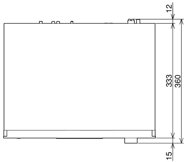
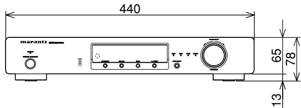
(mm)
OTHERS
The section describes the care and maintenance tasks that must be performed to optimize the operation of your Marantz equipment.
■ Cleaning of equipment external surfaces
The exterior finish of your unit will last indefinitely with proper care and cleaning, Never use scouring pads, steel wool, scourging powders or harsh chemical agents (e.g., lye solution), alcohol, thinner, benzine, insecticide or other volatile substances as these wil mar the finish of the equipment. Likewise, never use cloths containing chemical substances. If the equipment get dirty, wipe the external surfaces with a soft, lint-free cloth.
If the equipment becomes heavily soiled:
- dilute some washing up liquid in water, in a ratio of one part detergent to six parts water.
- dip a soft, lint-free cloth in the solution and wring the cloth till it is damp.
- wipe the equipment with the damp cloth.
- dry the equipment by wiping it with a dry cloth.

■ Repairs
Only the most competent and qualified service technicians should be allowed to service the factory-trained warranty station personnel have the knowledge and special facilities needed for repair and calibration of this precision equipment. After the warranty period has expired, repairs will be performed for a charge if the equipment can be returned to normal operation.
In the event of difficulty, refer to your dealer or write directly to the nearest location to you that is listed on the Marantz Authorized Service Station list. If writing, please include the model and serial number of the equipment together with a full description of what you think is abnormal about the equipment's behaviour.
www.marantz.com
You can find your nearest authorized distributor or dealer on our website.
U.S.A. Marantz America, Inc. 1100 Maplewood Drive, Itasca, IL 60143, U.S.A.
EUROPE Marantz Europe B.V. P.O. Box 8744, 5605 LS Eindhoven, The Netherlands
marantz ^® is a registered trademark.