
MECABLITZ 60 CT-1 - Photo lighting METZ - Free user manual and instructions
Find the device manual for free MECABLITZ 60 CT-1 METZ in PDF.

| Product type | Electronic flash for photography |
| Brand | METZ |
| Model | MECABLITZ 60 CT-1 |
| Guide number (ISO 100/21°) | 60 m (197 ft) |
| Operating modes | Non-TTL automatic, manual, motorized winder/motor |
| Available automatic apertures | 2 - 2,8 - 4 - 5,6 - 8 - 11 |
| Flash duration | 1/200 s (full power) to 1/20,000 s (partial power) |
| Color temperature | 5600 K |
| Power supply | Rechargeable NiCd 60-38 battery pack (included) |
| Recycling time | 5 s (M mode) to 0,25 s (motor mode) |
| Number of flashes per charge | 160 (full power) to 4500 (low power) |
| Supported film sensitivity | ISO 25 to 3200 |
| Dimensions (flash head) | 110 x 254 x 102 mm |
| Dimensions (generator unit) | 126 x 165 x 58 mm |
| Weight (flash head) | 650 g |
| Weight (generator unit with battery) | 1850 g |
| Reflector orientation | Vertical: click stops at 15°, 30°, 45°, 60°, 75°, 90°; Horizontal: 180° left and right with click stops at 90° and 180° |
| Wide-angle diffuser | Yes, built-in (increases vertical coverage from 42° to 65°) |
| Motorized recycling | Winder: 2 flashes/s; Motor: 5 flashes/s |
| Maintenance | Clean with a soft, dry or silicone cloth; do not use detergent |
| Safety | Do not disassemble (high voltage); avoid flammable gases; do not touch the flash window after use; keep away from eyes |
| Included accessories | Flash, bracket, battery pack 60-38, generator unit, connecting cord, charger, sync cable 60-50, user manual |
Frequently Asked Questions - MECABLITZ 60 CT-1 METZ
User questions about MECABLITZ 60 CT-1 METZ
0 question about this device. Answer the ones you know or ask your own.
Ask a new question about this device
Download the instructions for your Photo lighting in PDF format for free! Find your manual MECABLITZ 60 CT-1 - METZ and take your electronic device back in hand. On this page are published all the documents necessary for the use of your device. MECABLITZ 60 CT-1 by METZ.
USER MANUAL MECABLITZ 60 CT-1 METZ
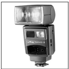
natural_image
Black-and-white photo of a Mezzelitz 80 CT device with attached harness and flashlight (no visible text or symbols on main body)
MECABLITZ 60 CT-1
Bedienungsanleitung
Gebruiksaanwijzing
Manuale istruzioni
Mode d'emploi
Operating instruction
Abmaße ca. in mm (B x H x T)
- Safety instructions 28
- Preparing the flashgun for use 29
2.1 Attaching the flashgun to a camera 29
2.2 Power supply 29
2.2.1 Battery replacement 29
2.3 Switching the flashgun on and off 29
2.4 Flash-ready indication....29
2.5 Correct exposure indication....29 - Automatic flash mode..... 30
- Manual flash mode 30
- Bounced flash 31
5.1 Bounced flash in automatic and TTL flash modes ..... 31
5.2 Bounced flash in manual flash mode 31 - Winder-/ Motordrive mode ..... 31
- Fill-in flash in daylight 32
7.1 Fill-in flash in automatic mode 32 - Illumination and wide-angle diffuser....32
- Exposure corrections 32
9.1 Exposure correction in automatic flash mode. 32 - Care and maintenance....33
- Technical data 33
- Optional accessories 34
Foreword
Congratulations on purchasing this METZ flashgun, and thank you for your confidence in METZ equipment.
It is only natural that you should want to use your flashgun straight away. However, it will be well worth your while to study these Operating Instructions carefully beforehand to ensure that you can operate the flashgun effectively and without any problems.
Please also oppen the back cover page with the illustrations.
This flashgun can be used with:
- All cameras with synch connection in conjunction with the supplied synch cable.
Brief survey of the operating functions:
Configuration and operating modes
- 60 CT-1 with synch cable: Automatic flash mode, Ch. 3, Page 30. Manual flash mode, Ch. 4, Page 30.
Points worth knowing
The mecablitz 60 CT-1 is supplied complete with 60-38 battery and charger.
Outstanding features:
- Universal, swivelling quadrolight reflector for bounced flash without having to forgo the benefits of automatic exposure control.
- Wide-angle diffuser.
- Automatic exposure control with a selection of 6 working apertures to easily resolve the problems associated with depth-of-field and to offer greater creative scope regarding camera settings.
- Power-saving thyristor light output control, particularly in the close-up range, for shorter recycle times and a higher number of flashes from just one battery charge
- Correct exposure confirmation (auto check) with a long display duration.
- Convenient calculator dial for all settings.
- Manual mode or operation with partial light output.
• Operation with winder cameras.
1. Safety instructions
- The flash unit is exclusively intended and approved for photographic use!
- Never fire a flash in the vicinity of flammable gases or liquids (petrol, solvents, etc.) - DANGER OF EXPLOSION!
- Never take flash shots of car, bus or train drivers, or of motorcycle and bicycle riders, whilst they are travelling. They could be blinded by the light and cause an accident!
- Never fire a flash in the immediate vicinity of the eyes! Flash fired directly in front of the eyes of a person or animal can damage the retina and lead to severe visual disorders - even blindness!
-
Only use the approved power sources listed in the Operating Instructions!
-
Do not expose batteries to excessive heat, sunshine, fire and the like!
- Never throw exhausted batteries on to a fire!
- Exhausted batteries should be immediately removed from the flash unit! Lye leaking out of spent batteries will damage the unit.
- Never recharge dry-cell batteries!
- Do not expose the flash unit or battery charger to dripping or splashing water!
- Protect the flash unit from excessive heat and humidity! Do not store the flash unit in the glove compartment of a car!
- Never place material that is impervious to light in front of, or directly on, the reflector screen. The reflector screen must be perfectly clean when a flash is fired. The high energy of the flash light will burn the material or damage the reflector screen if this is not observed.
- Do not touch the reflector screen after a series of flash shots. Danger of burns!
- Never disassemble the flashgun! DANGER: HIGH VOLTAGE!
- There are no components inside the flashgun that can be repaired by a layperson.
2. Preparing the flashgun for use
2.1 Attaching the flashgun to a camera
The flashgun can only be operated with synch cable on the camera.
Be sure to switch off the mecablitz by its main switch prior to mounting or removing the standard foot or SCA adapter. Before mounting or removing the flash unit, switch off both the camera and the flash unit!
Mounting the flashgun:
- Fasten the camera bracket with the bracket screw to the camera's tripod bush. For medium- and large-format cameras we recommend the use of the 70-35 bracket (optional accessory).
- Insert the camera bracket into the quick-release device ⑤ (fig. 1) of the bracket holder ④ (fig. 1) until it is audibly engaged (fig. 1).
- Secure the camera bracket with the locking screw.
- Connect the synch or SCA cable to the flashgun and camera or adapter.
2.2 Power supply
The flash unit can only be operated with the 60-38 battery.
Spent batteries must not be thrown into the domestic waste! Help keep the environment clean and discard spent batteries at corresponding collecting points!
Before using the mecablitz for the first time, open the battery compartment cover ⑥ (fig. 5) and remove the inserted cardboard insulating strip between the battery and contacts.
2.2.1 Charging the battery
The 60-38 rechargeable battery must only be charged with the battery charger (Table 2, Page 513). The operating voltage must be set on the battery charger prior to the charging operation.
Note ! During charging the flash unit must be turned off !
Recharging an exhausted battery to 80% of its capacity takes approx. 7 hours. During this time, the red monitoring light ⑧ remains illuminated. As soon as the battery has been recharged up to 80% of its capacity the red monitoring light ⑧ starts flashing. The green monitoring light ⑧ (fig. 5) remains illuminated during the whole recharging procedure. After a further six hours the accumulator is then fully charged
The battery is exhausted when recycling after a full-power flash takes more than 30 seconds. An exhausted battery must be immediately recharged.
2.3 Switching the flash unit ON and OFF
The flash unit is turned on with the main switch ⑨ (fig. 5). The in-use indicator ⑩ (fig. 5) of the generator will then light up. Push the main switch into position "0" to turn off the flash unit.
The mecablitz is ready for operation as soon as the flash-ready indicator ⑱ (fig. 3) lights up.
If the flash ready indicator ⑱ ((fig. 3) is illuminated while the power pack is switched off, then this indicates that the amount of light is no longer sufficient for a correct exposure.
2.4 Flash ready indication
The mecablitz is ready for operation as soon as the flash-ready indicator ⑱ (fig. 3) lights up. Only then can a flash be fired.
2.5 Correct exposure indication
The exposure o.k. indicator ⑨ (fig. 3) only lights up if the shot will be/has been correctly exposed in automatic or TTL flash mode.
This gives you the opportunity to manually fire a test flash in the auto flash mode in order to determine the correct aperture for a given subject - a procedure that can be otherwise daunting with bounce flash when the reflection conditions are difficult to judge in advance.
The test flash is triggered with the manual firing button.
If the exposure o.k. indicator ⑨ (fig. 3) remains dark after firing a test flash, then the next lower f-number must be set to widen the aperture, or the distance to the reflection surface or subject has to be
shortened. Thereafter repeat the test flash.
The f-stop established in this manner also has to be set on the camera.
Direct the flash unit with its sensor for the test flash in the same manner as for the subsequent flash shot.
3. Automatic Flash Mode
In the automatic flash mode the sensor ③ (fig. 1) measures the light reflected from the subject. The flash is cut off as soon as sufficient light has been emitted for correct exposure.
In this manner there is no need to calculate and set a new aperture when the distance is changed, provided that the subject remains within the indicated automatic flash range.
The photosensor of the flashgun must be directed at the subject, regardless of the direction at which the main reflector is pointing. The photosensor has a measuring angle of approx. 25^ , and it only measures the actual amount of light emitted by the flashgun.
Six working apertures are available in the automatic flash mode.
Adjusting procedure for the automatic flash mode:
Example:
Flash-to-subject distance: 5 m Film speed: ISO 100/21°
- Adjust the camera according to the manufacturer's operating instructions.
- Switch on the flashgun with the main switch ⑨ (fig. 5).
- Set the film speed with the setting knob ⑰ (fig. 3) on the flashgun's handle.
- Set the indicator window ⑫ (fig. 3) for one of the "C" auto apertures. The minimum lighting distance is approx. 10% of the maximum flash range.
- Await flash readiness indication – The flash ready indicator ⑱ lights up (fig. 3)
The subject should be within the middle third of the distance range. This gives the electronic control sufficient scope for compensation should this be necessary.
There is a certain measure of overlap between the individual automatic apertures. As a result of this overlap it is always possible to place the subject within the middle third of the range.
CAUTION with zoom lenses!
Due to their design they can cause a loss of light in the order of up to one f-stop. Furthermore, the effective aperture can also vary, depending upon the adjusted focal length. This must be compensated by manually correcting the aperture setting on the flashgun!
4. Manual Flash Mode
In this mode the flashgun will emit its full power. The flashgun can be adapted to the actual picture shooting situation by setting the corresponding aperture on the camera.
If the displayed value does not coincide with the actual distance, then the aperture have to be changed accordingly.
Adjusting procedure for the manual flash mode:
Example:
Flash-to-subject distance: 15 m Film speed: ISO 100/21°
- Set the camera as indicated in the camera's operating instructions.
- Turn on the flash unit with the main switch ⑨ (fig 5).
- Set the film speed with the setting knob ⑰ (fig. 3) on the flash handle.
- Set the indicator window ⑫ (fig. 3) at "M".
The distance will then be opposite an f-number. This f-number is the aperture to be set. - Await flash readiness indication – The flash ready indicator ⑱ (fig. 3) lights up.
At a flash-to-subject distance of 15 m (as in our example), an aperture
of f/4 has to be set on the camera. The adjusted aperture must be corrected when the wide-angle diffuser is used.
5. Bounce Flash
Photos shot with full frontal flash are easily recognizable by their harsh, dense shadows. This is often associated with a sharp drop of light from the foreground to the background.
This phenomenon can be avoided with bounce flash because the diffused light will produce a soft and uniform rendition of both the subject and the background. For this purpose the main reflector is turned in such a manner that the flash is bounce back from a suitable reflective surface (e.g. ceiling or walls of a room).
For this reason the main reflector can be turned vertically and horizontally. The following are the vertical lock-in positions for bounce flash:
- 15^ , 30^ , 45^ , 60^ , 75^ and 90^ (simply tilt the reflector to the required angle)
The head can be swivelled horizontally to the left and right by 180^ , and locks into position at 90^ and 180^ .
When swivelling the reflector vertically, it is essential to ensure that it is turned by a sufficiently wide angle so that direct light can no longer fall on the subject. Therefore, always tilt the reflector to at least the 60^ lock-in position.
The diffused light bounced back from the reflective surfaces results in a soft illumination of the subject.
The reflecting surface must be white or a neutral colour, and it must not be structured (e.g. wooden beams in the ceiling) as this could cast shadows. For colour effects just select reflective surfaces in the required colour.
5.1 Bounced flash in automatic and TTL flash modes
It is advisable to check prior to the actual exposure whether the light is sufficient for the selected aperture. Please refer to Ch. 2.5, for the corresponding procedure.
5.2 Bounce flash in manual flash mode
The required camera aperture in the manual flash mode is best established with an exposure meter. Observe the following rule of thumb if an exposure meter is not available
$$ \text { Camera aperture } = \frac {\text { guide number }}{\text { light distance } \times 2} $$
to establish the guide value for the aperture that can then be varied by +1 f-stop for the actual exposure.
6. Winder/Motordrive Mode
Definition:
In the winder/motordrive mode a series of pictures can be shot at the rate of several frames per second. The winder mode is based on partial light output levels.
Up to 2 flashes per second can be fired in the "Winder W" mode; up to 5 flashes per second are possible in the "Motordrive MD" mode.
Setting procedure for picture shooting in the winder flash mode:
- Set the camera as described in its Operating Instructions.
- Turn on the flash unit by its main switch ⑨ (fig. 5).
- Turn the setting knob ③ (fig. 4) for film speed on the reflector head. The setting mark must be positioned at the given ISO film speed.
- Set the setting dial ① (fig. 4) at "W" or "MD"
The distance will then be opposite an f-number. This f-number is the aperture to be set. - Await flash readiness indication – The flash ready indicator ⑱ (fig. 3) lights up.
The aperture to be set on the camera is then indicated on the scale opposite the flash-to-subject distance.
7. Fill-in Flash in Daylight
The mecablitz can also be used for fill-in flash in daylight to soften harsh shadows and lower the contrast, thereby producing a more balanced exposure when shooting against the light.
7.1 Fill-in flash in automatic mode
Use the camera, or a hand-held exposure meter, to establish the required aperture and shutter speed for a normal exposure. Ensure that the shutter speed either equals, or is slower than, the fastest flash synch speed (varies with the given camera model).
Example:
Established aperture = f/8; established shutter speed = 1/60 sec. Flash synch speed of the camera, e.g. 1/100 sec. (see operating instructions for the given camera).
The two established values for aperture and shutter speed can be set on the camera because the camera's shutter speed is slower than the camera's flash synch speed.
To maintain a balanced range of highlights, for instance in order to retain the character of the shadows, it is advisable to select the automatic aperture on the flashgun one setting lower than the aperture adjusted on the camera. In the above example the camera was adjusted to f/8. Consequently, we advise you to set an aperture of f/5.6 on the flashgun.
When shooting into the light, ensure that the backlight does not shine directly onto the sensor as this will confuse the flashgun's electronics!
8. Illumination and Wide-Angle Diffuser
The wide-angle diffuser widens the horizontal lighting angle from 62^ to 65^ , and the vertical lighting angle from 42^ to 60^ .
The wide-angle diffuser is intended for use with focal lengths of less than 28 . . 35 mm (for 24 x 36 mm), and less than 50 . .75 mm (for 6 x 6 cm).
If the wide-angle diffuser is not required, it should always be set in its park position under the reflector.
In the auto flash mode, the flash coverage widened by the wide-angle diffuser reduces the maximum flash ranges of the working apertures to approx. 70% of their original value. The new maximum flash ranges are indicated at the bottom edge of the setting slide.
When the wide-angle diffuser is being used in manual mode it will be necessary to set the next smaller f-number than the one indicated on the programming centre.
9. Exposure Corrections
The automatic exposure systems are based on a subject reflection factor of 25%, this being the average reflection factor for subjects shot with flash.
Dark backgrounds absorb a lot of light, while bright backgrounds reflect a great deal of light (e.g. backlit scenes), thereby resulting in subject overexposure or underexposure, respectively.
9.1 Exposure correction in automatic flash mode
To compensate the above mentioned effect, the exposure can be corrected by opening or stopping down the camera's aperture. With a bright background the sensor of the flashgun cuts out the flash too soon with the result that the actual subject is too dark. With a dark background the flash is cut out too late so that the actual subject is too bright.
Bright background: Open the camera aperture by 1/2 to 1 f-stop (e.g. from f/5.6 to f/4).
Dark background: Close the aperture by 1/2 to 1 f-stop (e.g. from f/8 to f/11).
10. Care and Maintenance
Remove dust and grime with a soft dry cloth, or a silicon-treated cloth. Do not use detergents as these may damage the plastic parts.
Forming the flash capacitor
The flash capacitor incorporated in the flashgun undergoes a physical change when the flashgun is not switched on for prolonged periods. For this reason it is necessary to switch on the flashgun for approx. 10 minutes every 3 months. The battery must supply sufficient power to light up the flash-ready light within one minute after the flashgun was switched on.
11. Technical Data
Guide numbers at ISO 100/21°:
In the metric system: 60 In the imperial system: 197
6 auto apertures at ISO 100/21°:
2 - 2,8 - 4 - 5,6 - 8 - 11
Flash durations:
- approx. 1/200 ... 1/20.000 sec.
- in M mode approx. 1/200 sec. at full light output.
- in winder mode approx. 1/3500 sec.
- in motordrive mode approx. 1/5000 sec.
Coverage angle of sensor: approx. 25°
Colour temperature: approx.: ca. 5600 K
Film speed: ISO 25 to ISO 3200
Synchronisation: low-voltage thyristor ignition
Number of flashes:
160*...4500.
* at full light output
Recycling time:
5 Sek. (in M mode) ... 0,25 Sek.
Swivelling ranges and locking positions of flash head:
| upwards: 15° | 30° | 45° | 60° | 75° | 90° |
| counter-clockwise | 90° | 180° | |||
| clockwise 90° | 180° |
Dimensions approx. in mm (wxhxd)
Flash unit 110 x 254 x 102
Generator 126 x 165 x 58
Weight:
Flash unit approx. 650 g
Generator with 60-38 battery approx. 1850 g
Table 1: Guide numbers at maximum light output (page 51)
Table 2: Chargers (page 51)
Included:
Flash unit, bracket, 60-38 battery, generator, connecting cable, charger, synch cable 60-50, operating instructions.
12. Optional accessories
Malfunctions and damage caused to the mecablitz 60 CT-1 due to the use of accessories from other manufacturers are not covered by our guarantee!
- Bounce diffuser 60-33 (Order No: 000060334) To soften heavy shadows with reflected light.
- Battery charger B 27 (Order No: 000100272) to charge the 60-38 battery and 60-39 NiCad pack
- Camera bracket 70-35 (Order No: 000070353) To attach the flashgun to the side of the camera.
- Camera cable release 45-26 (Order No: 000045265) The camera shutter can be tripped with the same hand that is holding the flashgun. This frees the other hand for focusing.
- Filter set 60-21 (Order No: 000060213) Consists of a set of 4 colour effects filters and 1 clear filter to hold any coloured foil.
- Mecalux 11 (Order No: 000000112) Slave triggering unit. For optical, delay-free remote triggering of slave flashguns by a camera-triggered flash. Responds also to infrared light beam. Does not require batteries.
- Mecalux Holder 60-26 (Order No: 000060264) To mount the Mecalux 11.
- Shoulder strap 50-31 (Order No: 000050319)
- Shoulder strap 60-80 (Order No: 000060802)
- Synch leads: Coiled synch lead 60-52 (Order No: 000060525) Synch extension lead 60-54 (5 m) (Order No: 000060541)
-
Telephoto attachment 60-42 (Order No: 000060420) For flash shots with telelenses. Nearly doubles the guide number. Infrared shots are also possible.
-
Connecting cable 60-61 (Order No: 000060611) 3 m cable
- Connecting cable, coiled, 60-59 (Order No: 000060592)
Disposal of batteries
Do not dispose of spent batteries with domestic rubbish.
Please return spent batteries to collecting points should they exist in your country!
Please return only fully discharged batteries.
Normally, batteries are fully discharged if:
- The device they powered switches itself off and indicates "Spent Batteries".
- They no longer function properly after prolonged use.
To ensure short-circuit safety please cover the battery poles with adhesive tape.
Indice
natural_image
Aerial view of an industrial complex with multiple factory buildings and surrounding farmland (no visible text or signage)natural_image
Illustration of a modern flat-screen TV unit with control panels and front-mounted screens (no text or symbols visible)Consumer electronics
natural_image
Exterior view of a modern office building (no signage)Photoelectronics
natural_image
Close-up of a robotic arm connecting wires to a mechanical component (no visible text or symbols)Plastics technology
natural_image
Close-up of a precision laser cutting through a circuit board (no visible text or symbols)Industrial electronics
Metz. Always first class.
C ∈
703 47 0079.A1
D F NL GB I E
- MECABLITZ 60 CT-1
- Foreword
- Points worth knowing
- Outstanding features:
- Safety instructions
- Preparing the flashgun for use
- Attaching the flashgun to a camera
- Mounting the flashgun:
- Power supply
- Charging the battery
- Switching the flash unit ON and OFF
- Flash ready indication
- Correct exposure indication
- Automatic Flash Mode
- Adjusting procedure for the automatic flash mode:
- Example:
- Manual Flash Mode
- Adjusting procedure for the manual flash mode:
- Bounce Flash
- Bounced flash in automatic and TTL flash modes
- Bounce flash in manual flash mode
- Winder/Motordrive Mode
- Setting procedure for picture shooting in the winder flash mode:
- Fill-in Flash in Daylight
- Fill-in flash in automatic mode
- Illumination and Wide-Angle Diffuser
- Exposure Corrections
- Exposure correction in automatic flash mode
- Care and Maintenance
- Forming the flash capacitor
- Technical Data
- Included:
- Optional accessories
- Disposal of batteries
- Indice
Brand : METZ
Model : MECABLITZ 60 CT-1
Category : Photo lighting