K7S41 - Motherboard ASROCK - Free user manual and instructions
Find the device manual for free K7S41 ASROCK in PDF.
Download the instructions for your Motherboard in PDF format for free! Find your manual K7S41 - ASROCK and take your electronic device back in hand. On this page are published all the documents necessary for the use of your device. K7S41 by ASROCK.
USER MANUAL K7S41 ASROCK
ASRocK K7S41 K7S41GX User Manual Version 1.0 Published December 2003 Copyright©2003 ASRock INC. AII rights reserved.
Copyright Notice: No part of this manual may be reproduced, transcribed, transmitted, or translated in any language, in any form or by any means, except duplication of documentation by the purchaser for backup purpose, without written consent of ASRock Inc: Products and corporate names appearing in this manual may or may not be regis- tered trademarks or copyrights of their respective companies, and are used only for identification or explanation and to the owners’ benefit, without intent to infringe Disclaimer: Specifications and information contained in this manual are furnished for informa- tional use only and subject to change without notice, and should not be constructed as à commitment by ASRock. ASRock assumes no responsibility for any errors or omissions that may appear in this manual With respect to the contents of this manual, ASRock does not provide warranty of any kind, either expressed or implied, including but not limited to the implied warran- ties or conditions of merchantability or fitness for a particular purpose. In no event shall ASRock, its directors, officers, employees, or agents be liable for any indirect, special, incidental, or consequential damages (including damages for loss of profits, loss of business, loss of data, interruption of business and the like), even if ASRock has been advised of the possibility of such damages arising from any defect or error in the manual or product ASRock Website: http://www.asrock.com
2 Installation Pre-installation Precautions
2.1 CPU Installation . …
2.2 Installation of CPU Fan and Heatsink.…
3.3 Advanced, Security, P Power, Boot, and Exit Menus
4.2.3 Utilities Menu. as 23
Thank you for purchasing ASRock K7S41 / K7S41GX motherboard, a reliable moth- erboard produced under ASRock's consistentiy stringent quality control. It delivers excellent performance with robust design conforming to ASRock's commitment to quality and endurance.
Chapter 1 and 2 of this manual contain introduction of the motherboard and step-by-
step installation guide. Chapter 3 and 4 contain basic BIOS setup and support CD information. More information of advanced BIOS setup is offered on page 24 for advanced users’ reference Because the motherboard specifications and the BIOS software might be updated, the content of this manual will be subject to change without notice. In case any modifications of this manual occur, the updated version will be available on ASRock website without further notice. You may find the latest memory and CPU support lists on ASRock website as well. ASRock website http://www.asrock.com
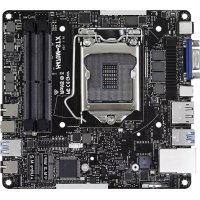
Platform: CPU: Chipsets: Memory: Floppy Port: Audio: LAN: Hardware Monitor: PCI slots: AGP slot: AMR slot: USB 2.0: ASRock 1/07: Micro ATX Form Factor: 9.6-in x 7.8-in, 24.4 cm x 19.8 cm Supports Socket A (462 pins) for AMD Athlon" XP / Duron processor North Bridge (K7S41): sis 741, FSB@400 MHz, AGP 8X/4X North Bridge (K7S41GX): sis 741GX, FSB@333 MHz, AGP 8X/4X South Bridge: SiS 963L, supports USB 2.0, ATA 133 2DDR DIMM Slots: DDR1 and DDR2 K7S41: PC3200 (DDR400) / PC2700 (DDR333) / PC2100 (DDR266), Max. 2GB; K7S41GX: PC2700 (DDR333) / PC2100 (DDR266), Max. 2GB IDE1: ATA 133 / Ultra DMA Mode 6, IDE2: ATA 133 / Ultra DMA Mode 6, Supports up to 4 IDE devices Supports up to 2 floppy disk drives
5.1 channels AC'97 Audio
Speed: 802.3u (10/100 Ethernet), supports Wake-On-LAN CPU temperature sensing, Chassis temperature sensing, CPU overheat shutdown to protect CPU life (ASRock U-COP)(see CAUTION 1), CPU fan tachometer, Chassis fan tachometer, Voltage monitoring: +12V, +5V, +3V, Voore 2 slots with PCI Specification 2.2 1 AGP slot, supports 1.5V, 8X/4X AGP card (see CAUTION 2) 1 slot, supports ASRock MR card (Optional) 6 USB 2.0 ports: includes 4 default USB 2.0 ports on the rear panel, plus one connector to support 2 additional USB 2.0 ports (see CAUTION 3) 1 PS/2 mouse port, 1 PS/2 keyboard port, 1 VGA port, 1 parallel port: ECP/EPP support, 1 RJ 45 port, 4 default USB 2.0 ports, 1 Game port, Audio Jack: Line Out / Line In / Microphone
While GPU overheat is detected, the system will automatically shutdown. Please check if the CPU fan on the motherboard functions properly before you resume the system. To improve heat dissipation, remember to spray thermal grease between the CPU and the heatsink when you install the PC system. Do NOT use a 3.3V AGP card on the AGP slot of this motherboard! It may cause permanent damage! Power Management for USB 2.0 works fine under Microsoft® Windows® XP SP1/2000 SPA. It may not work properly under Microsoft? Windows® S8/ME. Please refer to Microsoft® official document at htip:/mw microsoft. comihdc/hwdev/bus/USB/USB2support.mspx Although this motherboard offers stepless control, it is not recommended to perform over clocking. Frequencies other than the recommended CPU bus frequencies may cause the instability of the system or damage the CPU. The CPU host frequency of this motherboard is determined by the jumper-setting. You must set the FSB jumper according to your AMD CPU before you use the “Manual” option as he FSB setting in BIOS setup to perform over clocking. Please check page 24 for details.
PS2_USB_PWR1 Jumper CPU Fan Connector (CPU_FAN1) CPU Socket North Bridge Controller 184-pin DDR DIMM Slots (DDR 1-2) ATX Power Connector (ATXPWR1) Secondary IDE Connector (IDE2, Black) Primary IDE Connector (IDE, Blue) AGP Slot (1.5V_AGP4) South Bridge Controller Clear CMOS (CLREMOS1, solder points) Clear CMOS (CLRCMOS2, 2-pin jumper) Chassis Fan Connector (CHA_FAN1) Power LED Connector (PWR_LED1) System Panel Connector (PANEL1) 16 Chassis Speaker Connector (SPEAKER 1)
Chapter 2 Installation
K7S41 / K7S41GX is a Micro ATX form factor (9.6-in x 7.8-in, 24.4 cm x 19.8 cm) motherboard. Before you install the motherboard, please study the configura- tion of your chassis to ensure that the motherboard fits into it Pre-installation Precautions Take note of the following precautions before you install motherboard compo- nents or change any motherboard settings.
1. Unplug the power cord from the wall socket before touching any component.
2. To avoid damaging the motherboard components due to static electricity,
NEVER place your motherboard directly on the carpet or the like. Also re- member to use a grounded wrist strap or touch a safety grounded object before you handle components.
3. Hold components by the edges and do not touch the ICs.
4. Whenever you uninstall any component, place it on a grounded antistatic
pad or in the bag that comes with the component. Before you install or remove any component, ensure that the \ power is switched off or the power cord is detached from the power supply. Failure to do so may cause severe damage to the motherboard, peripherals, and/or components
CPU Installation Unlock the socket by lifting the lever up to à 90° angle. Position the CPU directly above the socket such that its marked corner matches the base of the socket lever. Carefully insert the CPU into the socket until i its in place. The CPU fits only in one correct orientation. DO NOT force the CPU into the socket to avoid bending of the pins. When the CPU is in place, press it firmlÿ on the socket while you push down the socket lever to secure the CPU. The lever clicks on the side tab to indicate that it is locked STEP1 STEP 2ISTEP 3. STEP4: LiftUp The SocketLever Match The CPU Marked Corner _ Push Don AndLock to The Socket Marked Comer The SocketLever Installation of CPU Fan and Heaïisink This motherboard adopts 462-pin CPU socket to support AMD Athlon XP / Duron CPU. It requires larger heatsink and cooling fan to dissi- pate heat. You also need to spray thermal grease between the CPU and the heatsink to improve heat dissipation. Make sure that the CPU and the heatsink are securely fastened and in good contact with each other. Then connect the CPU fan to the CPU_FAN connector (CPU_FAN1, see page 7/page 8, No. 2). For proper installation, please kindly refer to the instruction manuals of the CPU fan and the heatsink.
K7S41 ! K7S41GX motherboard provides two 184-pin DDR (Double Data Rate) DIMM slots. Please make sure to disconnect power supply before adding or l f removing DIMMS or the system components. Step 1. Unlock a DIMM slot by pressing the retaining clips outward Step 2. Align a DIMM on the slot such that the notch on the DIMM matches the break on the slot. <=hotch æ-hreak <-notch æ=break The DIMM ony fits in one correct orientation. It will cause permanent damage to the motherboard and the DIMM if you force the DIMM into the slot at incorrect orientation. Step 3. Firmly insert the DIMM into the slot until the retaining clips at both ends fully snap back in place and the DIMM is properly seated.
Expansion Slots (PCI, AMR, and AGP Slots) There are 2 PCI slots, 1 AMR slot, and 1 AGP slot on K7S41 / K7S41GX motherboard. PCI slots: PCI slots are used to install expansion cards that have the 32-bit PCI interface. AMR slot: The AMR slot is used to insert an ASRock MR card (optional) with v.92 Modem functionality. AGP slot: The AGP slot is used to install a graphics card. The ASRock AGP slot has
à special design of clasp that can securely fasten the inserted graphics card. Please do NOT use a 3.3VAGP card on the AGP slot of this motherboard! It may cause permanent damage! For the voltage information of your graphics card, please check with the graphics card vendors. Installing an expansion card Step 1. Step 2. Step 3. Step 4. Step 5. Step 6. Before installing the expansion card, please make sure that the power supply is switched off or the power cord is unplugged. Please read the documentation of the expansion card and make necessary hardware settings for the card before you start the installation. Remove the system unit cover (if your motherboard is already installed in a chassis). Remove the bracket facing the slot that you intend to use. Keep the screws for later use. Align the card connector with the slot and press firmly until the card is completely seated on the slot Fasten the card to the chassis with screws. Replace the system cover.
Theillustration shows how jumpers are selup. When the jumper cap is placed on pins, the jumper is J 4 “SHORT”. If no jumper cap is placed on the pins, the jumper is “OPEN”. The illustration shows a 3-pin jumper whose pin1 and pin2 are *SHORT” when LES jumper cap is placed on these 2 pins. Short Open Jumper Setting FSB Select K7S41: Jumpers 23 23 23 12 Geep7p8No2n| Fe seu CO Oroseu (D rose CO re se Do) 12 Ex 12 12 Fee seu DO) roses CO se se OÙ rss seu D.) rse_seco CO rss seu OO rse_seco OI: rs8_seo DJ: rs 200uH F2 2664 Feu ss FS2 «oo K7S41GX: rss secs Oo) rseset COX Fse_seci OEI°) rss seco COS Fss-seuo © OI Fss_seco OI Fs8 2004 F8 266 Fu ss Note: The setting of the CPU front side bus frequency of this motherboard is by means of the adjustment of jumper-setting. You must set the FSB jumper according to your AMD CPU before you use the “Manual” option as the FSB setting in BIOS setup to perform over clocking. Please follow the figures above to set the CPU front side bus frequency.
(ee p7Ip8 No. 1) 24 Short pin2, pin3 to enable +5VSB (standby) for PS/2 or USB wake up events. Note: To select +5VSB, it requires 2 Amp and higher standby current provided by power supply. +v +vs8 JR1(see p.7/p.8 No. 24) AL1(see p.718 No. 23) TR A Note: _Ifthe jumpers JL1 and JR1 are short (see the figure above), both front panel and rear panel audio connectors can work.
Clear CMOS (CLRCMOS1, saider points) (see p7Ip.8 No. 11) Note: CLRCMOS1 and CLRCMOS2 allow you to clear the data in CMOS. The data in CMOS includes system setup information such as system password, date, time, and system setup parameters. There are 2 ways for you to clear and reset the system parameters to the default setup. Please turn off the computer and unplug the power cord, then you may either short the solder points on CLRCMOS1 by using metal material, e.g., a paper clip for 3 seconds; or you may use a jumper cap to short the pin on CLRCMOS2 for 3 seconds. Please remember to remove he paper clip or the jumper cap after clearing the CMOS. If you need to clear the CMOS when you just finish updating the BIOS, you must boot up the system first, and then shut it down before you do the clear-CMOS action
For example, “Athlon XP 2000+" is an 1666MHz CPU: 12.5 (Muitiplier) X 133MHz (External frequency) = 1666MHz FID jumpers setting: The jumper caps are not provided by ASRock. Please understand that ASRock d $ does not guarantee and support the adjustment of multiplier. These jumpers setting may not apply to all multiplier-locked or even some unlocked AMD CPU. Frequencies other than the recommended CPU bus frequencies may cause the instability of the system or damage the CPU.
\ Connectors are NOT jumpers. DO NOT place jumper caps over these connectors. Placing jumper caps over the connectors will cause perma- nent damage ofthe motherboard! Connector Figure Description FDD Connector (see p7p8 No 17) Pini FLOPPYI the red-striped side to Pin Note: Make sure the red-striped side of the cable is plugged into Pin1 side of the connector. Primary IDE Connector (Blue) Secondary IDE Connector (Black) (G9-pinIDE1, see p7/p.8 No. 8) (G9-pin IDE2, see p.7/p8 No. 7) F [ Toni IDET lin IDE2 connect the blue end 3 gp connect the black end to the motherboard CHER SEEN | to the IDE devices 80-conductor, ATA 66/100/133 cable Note: If you use only one IDE device on this motherboard, please set the IDE device as “Master”. Please refer to the instruction of your IDE device vendor for the details. Besides, to optimize compatibility and performance, please connect your hard disk drive to the primary IDE connector (IDE, blue) and CD-ROM to the secondary IDE connector (IDE2, black).
USB 2.0 Connector (pin USB45) (ee p7Ip8 No. 18) use Pure There are 4 default USB 2.0 ports on the rear panel. If the rear USB ports are not sufficient, this USB 2.0 connector is available to support 2 additional USB 2.0 ports. Infrared Module Connector G-pinIR1) (ee p7Ip8 No. 19) This connector supports an optional wireless transmitting and receiving infrared module. Internal Audio Connectors Céspin CD, pin AUX) (CDI: see p71p8 No 28) (AUX: see p 71.8 No 29)
These connectors allow you to receive stereo audio input from sound sources such as à CD- ROM, DVD-ROM, TV tuner card, or MPEG card. Front Panel Audio Connector @-pin AUDION) (see p71p8 No. 25) This is an interface for front panel audio cable that allows conve- nient connection and control of audio devices. System Panel Connector {-pin PANEL1) {see p.7/p.8 No. 15)
This connector accommodates several system front panel functions: Chassis Speaker Connector pin SPEAKER 1) (ee p7Ip8 No. 16)
speaxen louis our Please connect the chassis speaker to this connector. Chassis Fan Connector G-pin CHA_FANT) (see p.7IP.8 No. 13) eno
Please connect a chassis fan cable to this connector and match the black wire to the ground pin. CPU Fan Connector G-pin GPU_ FAN) (see p71p8 No.2) Please connect a CPU fan cable to this connector and match the black wire to the ground pin
ATX Power Connector (0-pin ATXPWR1) (ee p7Ip8 No 8) Please connect an ATX power supply to this connector. Serial port connector (G-pin COM) (eee p71p8 No22) ocost This COM1 connector supports à serial port module Power LED Connector G-pin PWR_LEDI) (see p.71p8 No. 14) LED. PLéD+ bLéD+ Please connect a 3-pin power LED cable to this connector.
This section explains how to use the BIOS Setup Utility to configure your system The Flash Memory on the motherboard stores the BIOS Setup Utility. You may run the BIOS Setup when you start up the computer. Please press <F2> during the Power- On-Self-Test (POST) to enter the BIOS Setup Utility, otherwise, POST will continue with its test routines. If you wish to enter the BIOS Setup after POST, restart the system by pressing <Ctl> + <Alt> + <Delete>, or by pressing the reset button on the system chassis You may also restart the system by turning the system off and then back on. The BIOS Setup Utility is designed to be user-friendly. It is a menu-driven program, which allows you to scroll through its various sub-menus and select among the predetermined choices Because the BIOS software is constantiy being updated, the following BIOS setup screens and descriptions are for reference purpose only, and may not exactly match what you see on your screen.
The top of the screen has à menu bar with the following selections: MAIN Sets up the basic system configuration ADVANCED Sets up the advanced features SECURITY Sets up the security features POWER Configures Power Management features BOOT Configures the default system device that is used to locate and load the Operating System EXIT Exits the current menu or the BIOS Setup To access the menu bar items, press the right or left arrow key on the keyboard until the desired item is highlighted.
Atthe bottom of the Setup Screen is a legend bar. The following table lists the keys in the legend bar with their corresponding functions.
When you enter the BIOS Setup Utility, the following screen appears. RATS SETUP UTILE VERSION Ie PRE Neon Poner on Eu 1 Setup Help System Date 11 2003 Thu System Time Æ Month: Jan Dee Day Floppy Déives Year 1940 IDE Devices
“Total Memory DRI DDR2 Fin :Selcet tem Fse:Eni Men EnterSe F9:Setup Defauls FO:Save à Exit System Date [Month/Day/Year] Set the system date that you specify. Valid values for month, day, and year are Month: (Jan to Dec), Day: (1 to 31), Year: (up to 2099). Use ? } keys to move between the Month, Day, and Year fields. System Time [Hour:Minute:Second] Set the system to the time that you specify. Use ? Ÿ keys to move between the Hour, Minute, and Second fields. Floppy Drives Use this to set the type of floppy drives installed. IDE Devices Use this to configure IDE devices.
TYPE To set the type of the IDE device, first, please select ‘IDE Devices” on Main menu and press <Enter> to get into the sub-menu. Then, select among “Primary IDE Master”, “Primary IDE Slave”, “Secondary IDE Master”, and “Secondary IDE Slave” to make configuration of its type. Below are the configuration options. juge Fam DE ter Ta Type ce | nm dde ie Precompensation S£ecs LAUTOI 10 set Fier HSekerten Change Values F9 Scur Delais EnciPretious Menu Enr Selet Sub Menu F:Save it [USER]: lt allows user to manually enter the number of cylinders, heads, and sectors per track for the drive. Before attempting to configure a hard disk drive, make sure you 4 have the correct configuration information supplied by the drive manufacturer. Incorrect settings may cause the system to fail to recognize the installed hard disk. [Auto]: Select [Auto] to automatically detect hard disk drive. If auto- detection is successful, the BIOS Setup automatically fills in the correct values for the remaining fields on this sub-menu. If the auto- detection fails, it may due to that the hard disk is too old or too new If the hard disk was already formatted on an older system, the BIOS Setup may detect incorrect parameters. In these cases, select [User] to manually enter the IDE hard disk drive parameters: After entering the hard disk information into BIOS, use a disk utility, such as FDISK, to partition and format the new IDE hard disk drives. This is necessary so that you can write the data into or read the data from the installed hard disk. Please make sure to set the partition of the Primary IDE hard disk drives to make them active.
[CD/DVD]: This is used for IDE CD/DVD drives. IARMDJ: This is used for IDE ARMD (ATAPI Removable Media Device), such as MO. Cylinders This is used to configure the number of cylinders. Refer to the drive documentation to determine the correct value Heads This is used to configure the number of read/write heads. Refer to the drive documentation to determine the correct values Write Pre-compensation Enter Write Pre-compensation sector. Refer to the drive documentation to determine the correct value. Sectors This is used to configure the number of sectors per track. Refer to the drive documentation to determine the correct value. Maximum Capacity This field shows the drive's maximum capacity as calculated by the BIOS based on the drive information you entered LBA Mode This allows user to select the LBA mode for a hard disk > 512 MB under DOS and Windows; for Netware and UNIX user, select [Off] to disable the LBA mode. Block Mode Set the block mode to [On] will enhance hard disk performance by reading or writing more data during each transfer. Fast Programmed 1/0 Modes This allows user to set the PIO mode to enhance hard disk performance by optimizing the hard disk timing. 32 Bit Transfer Mode It allows user to enable 32-bit access to maximize the IDE hard disk data transfer rate. Ultra DMA Mode Ultra DMA capability allows improved transfer speeds and data integrity for compatible IDE devices. Set to [Disabled] to suppress Ultra DMA capability.
3.3 Advanced, Security, Power, Boot, and Exit Menus
Detailed descriptions of these menus are listed in the Appendix. See page 24.
Chapter 4 Software Support
4.1 Install Operating System
This motherboard supports various Microsoft® Windows® operating systems 98 SE / ME / 2000 / XP. Because motherboard settings and hardware options vary, use the setup procedures in this chapter for general reference only. Refer to your OS documentation for more information
4.2 Support CD Information
The Support CD that came with the motherboard contains necessary drivers and useful utilities that will enhance the motherboard features.
4.2.1 Running The Support CD
To begin using the support CD, insert the CD into your CD-ROM drive. The CD automatically displays the Main Menu if *AUTORUN" is enabled in your computer. If the Main Menu did not appear automatically, locate and double click on the file ASSETUP.EXE from the BIN folder in the Support CD to display the menus.
The Drivers Menu shows the available devices drivers if the system detects installed devices. Install the necessary drivers to activate the devices.
4.2.3 Utilities Menu
The Utilities Menu shows the applications software that the motherboard supports. Click on a specific item then follow the installation wizard to install it
4.2.4 ASRock PC-DIY Live Demo Program
ASRock presents you a multimedia PC-DIY live demo, which shows you how to install your own PC system step by step. You may find the file through the following path:
.\MPEGAV \AVSEQ01.DAT
To see this demo program, you may run Microsoft® Media Player” to play the file.
4.2.5 Contact Information
If you need to contact ASRock or want to know more about ASRock, welcome to visit ASRock's website at http:/www.asrock.com; or you may contact your dealer for further information
Appendix: Advanced BIOS Setup This section will introduce you the following BIOS Setup menus: “Advanced,” “Security,” “Power,” “Boot,” and “Exit.”
1. Advanced BIOS Setup Menu
ANTBIOS SETUPUTIENV- VERSION Sa 1 Senpreip Spread Spectrum CPU Hon Frequency By Jumper Enter 1o enable or Actual Frequency FMH diable the feature DRAM Frequeney Auto spread spectrum Flexibility Option Disabled } Chipset Configuration ee Fonfiguration Monitor FiHelp ge Value F9:Setup Defauts EseFa Enter let RSub-Meny — F10:Save & Exit Spread Spectrum: This field should always be [Disabled] for better system stability. CPU Host Frequency: [By Jumper]: it is recommended to select this option, which will let the CPU host frequency of this motherboard determined by the jumper-setting [Manual]: This allows user to set CPU host frequency manually. However, because the CPU host frequency of this motherboard is determined by the jumper-setting, you must set the FSB jumper adjustment according to your AMD CPU before you use this “Manual” option as the FSB setting in BIOS setup to perform over clocking. This is not recommended unless you thoroughly know the feature. Wrong setup may cause problems during operation. DRAM Frequency: If set to [Auto], the motherboard will detect the inserted memory module(s) and automatically assign appropriate frequency. You may select other value as the operating frequency: [133MHz (DDR266)], [166MHz (DDR333)], [200MHz (DDR400)]. Please note that the option [200MHz (DDR400)] will be available only when K7S41 motherboard is installed. Flexibility Option: The default value of this option is [Disabled]. It will allow better tolerance for memory compatibility when it is set to [Enabled].
Chipset Configuration:
TRI Chipset Configuration Setup Help Onboard VGA Share Memory AGP Aperure Size USB Controller Enabled « Enabled Support Disabled DRAM CAS y auto Over Veore Voltage Disabled Fieip H:Seleetttem Change Values F9:Setup Defaults Esc:Previous Menu EntersSeleet_pSub-Meny FI0:Save & Exit OnBoard VGA Share Memory: This allows you to select the size of share memory for onboard VGA. Onboard VGA will get better resolution if larger size of share memory is selected AGP Aperture Size: It refers to a section of the PCI memory address range used for graphics memory. It is recommended to leave this field at the default value unless the installed AGP card's specifications requires other sizes. USB Controller: Use this to enable or disable the use of USB controller. USB 2.0 Controller: Use this to enable or disable USB 2.0 controller. If this is set to [Disabled], USB Controller will run at USB 1.1. USB Device Legacy Support: Use this to enable or disable the support to emulate legacy 1/O devices such as mouse, keyboard. etc. DRAM CAS Latency: This is used to adjust the means of memory accessing Configuration options: [Auto], [2T], [2.ST], [3T] Please note that not all the DDR DIMMS can support CAS latency=3T. Over Vcore Voltage: This feature allows you to increase the CPU Vcore voltage by 3% or 6%. The default value is [Disabled] It is not recommended to enable “Over Vcore Voltage” feature. Doing so may cause CPU damage. 25!
Resource Configuration:
Resource Configuration 1 SeupHelp_] Enter> to select PCI PCI Latency Timer (PCI Cloeks) loc. on Primary Graphics Adapter Per default seting for the AGP Data Rate Auto best PCT performance AGP Fast Write Enabled Fan Esc:Previous Menu Select em FoSetup Defaults FID:Save & En: ‘Change Value Enter:Seleet_pSub-Menu PCI Latency Timer (PCI Clocks): The default is 32. It is recommended to keep the default value unless the installed PCI expansion cards specifications require other settings. Primary Graphics Adapter: If both AGPcard and PCI graphics card are installed on the mother board, you may use this option to select PCI or AGP as the primary graphics adapter. AGP Data Rate: The default setting is [Auto]. You may select between [BX] or [4X] for an AGP 3.0 card, or select among [4X], [2X], [1X] for an AGP 2.0 card. AGP Fast Write: This allows you to enable or disable the feature of AGP fast write protocol support Peripheral Configuration: ANTIOS SERUPONENN VERSION Ie TRRET Peripherl Configuration D Sep Help Enter to enable or OnBoard FDC disable the floppy OnBoard Serial Port Auto drive controller OnBoard Infrared Port Disubled OnBoard Parallel Port Auto Parallel Port Mode ECP-EPP sion 19 Parallel Port IRQ Auto Parallel Port DMA Channel Auto OnBoard Midi Port Disubled Midi D 5 OnBoard Game Port 200 OnBoard IDE Both OnBoard LAN Enabled OnBoard AC°97 Audio Auto OnBoard MC°97 Modem Auto
OnBoard FDC: Use this to enable or disable floppy drive controller. OnBoard Serial Port: Use this to set addresses for the onboard serial ports or disable serial ports. Configuration options: [Auto], [Disabled], [3F8 / IRQ4 / COM!], [2F8/ IRQ3 / COM2] [3E8 / IRQ4/ COM], [2E8 / IRQ3 / COM4]. OnBoard Infrared Port: You may select [Enabled] or [Disabled] for this onboard infrared port feature. OnBoard Parallel Port: Select Parallel Port address or disable Parallel Port. Configuration options: [Auto], [Disabled], [378], [278] Parallel Port Mode: Set the operation mode of the parallel port. The default value is [ECP+EPP]. If this option is set to [ECP+EPP], it will show the EPP version in the following item, “EPP Version” OnBoard Midi Port: Select address for Midi Port or disable Midi Port. Configuration options: [Disabled], [330], and [300]. Midi IRQ Select: Use this to select Midi IRQ OnBoard Game Port: Select address for Game Port or disable Game Port Configuration options: [Disabled], [200], [208]. OnBoard IDE: You may enable either the primary IDE channel or the secondary IDE channel. Or you may enable both the primary and the secondary IDE channels by selecting [Both]. Set to [Disabled] will disable the both. Configuration options: [Disabled], [Primary], [Secondary], [Both]. OnBoard LAN: This allows you to enable or disable the onboard LAN feature. OnBoard AC’97 Audio: Select [Disabled], [Auto] or [Enabled] for the onboard AC'97 Audio feature OnBoard MC’97 Modem: Select [Disabled], [Auto] or [Enabled] for the onboard MC'97 Modem feature System Hardware Monitor: You may check the status of the hardware on your system. It allows you to monitor the parameters for CPU temperature, Mother- board temperature, CPU fan speed, and critical voltage. TRUT 1 seen Change Values F9-Seip Deus ous Menu erSelret PSabMege — FI0:Save & Ex
Setup Help Supervisor Password Clear L_SenpHelp 1 User Password Clear Enter to set he superviser password Set Supervisor Password Set User Password cr Password Check Setup Fin H:Select rem Change Values F9:Setup Defaults seen =Sclee Menu EmierSeleet PSubMenu FI0:Save & Ext Supervisor Password: This field shows the status of the Supervisor Password [Clear]: No password has been set. [Set]: Supervisor password has been set. User Password: This field shows the status of the User Password. [Clear]: No password has been set. [Set]: User password has been set Set Supervisor Password: Press <Enter> to set the Supervisor Password. Valid password can be a 1 to 6 alphanumeric characters combination. If you already have a password, you need to enter your current password first in order to create a new password Set User Password: Press <Enter> to set the User Password. Valid password can be a 1 to 6 alphanumeric characters combination. If you already have a password, you need to enter your current password first in order to create a new password Password Check: Select the check point for “Password Check”. Configuration options: [Setup], [Always]. If [Setup] option is selected, the “Password Check” is performed before BIOS setup. If [AÏways] option is selected, the “Password Check" is performed before both boot-up and BIOS setup.
LE MR spend To RAM (53) Dre Video on $3 Resume Disable <Enee to select on ÀC/ Power Loss Power OI automdeteet or disable Ring-In Power On Disabled fe ACPI 53 feature PCT Devices Power On Disabled eyboard Power On Disabled RTC Alarm Power On Disabled RTC Alarm Date Evervday RTC Alarm Hour a RTC Alarm Minute 30 RTC Alarm Second 30 Fielp 1 Set em “Change Values F9:Setup Defaults EsciEni = Seleet Menu Enr Select DSub-Menu F10-Save & Exit Suspend to RAM (S3): This field allows you to select whether to auto-detect or disable “ACPI S3" feature. Select [Auto] will enable this feature if the system supports it Repost Video on S3 Resume: This feature allows you to repost video on S3 resume. It is recommended to enable this feature under Microsoft® Windows® 98/ME Restore on AC/Power Loss: This allows you to set the power state after an unexpected AC/power loss. If [Power Off] is selected, the AC/power remains off when the power recovers. If [Power On] is selected, the AC/power resumes and the system starts to boot up when the power recovers. Ring-In Power On: Use this to enable or disable Ring-in signals to turn on the system from the power-soft-off mode. PCI Devices Power On: Use this to enable or disable PCI devices to turn on the system from the power-soft-off mode. PS/2 Keyboard Power On: Use this to enable or disable PS/2 keyboard to turn on the system from the power-soft-off mode RTC Alarm Power On: Use this to enable or disable RTC (Real Time Clock) to power on the system. If [Enable] is selected, you must fill the RTC Alarm Date / Hour / Minute / Second sub-fields with the actual wake up time you desire