USER MANUAL SU-700 TECHNICS
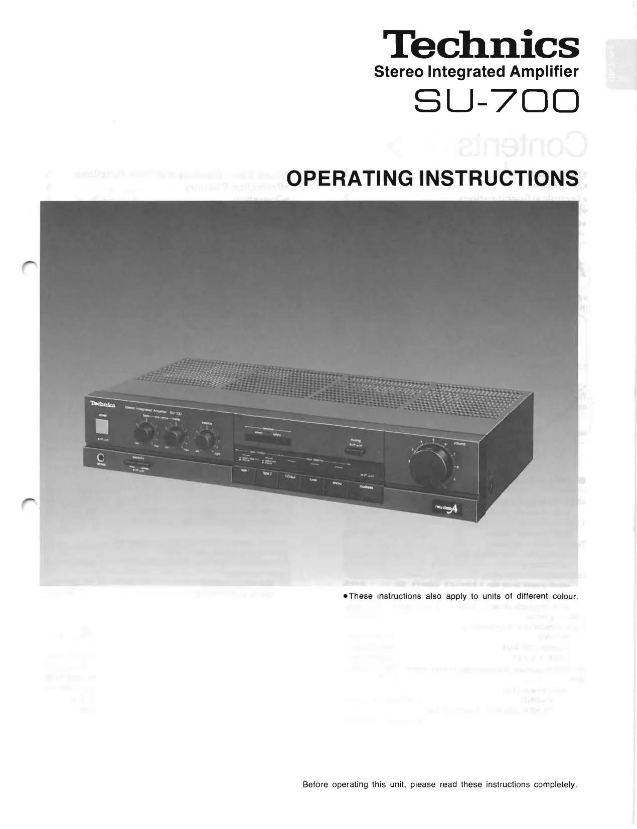
Stereo Integrated Amplifier
SU-700
OPERATING INSTRUCTIONS
These instructions also apply to units of different colour.
We want to thank you for selecting this product and to welcome you to the growing family of satisfied Technics product owners around the world.
We feel certain you will get maximum enjoyment
from this new addition to your home.
Please read these operating instructions carefully, and be sure to keep them handy for convenient reference.
Contents
Accessory 2
Before Use 2
-Technical Specifications 2
Suggestions for Safety 3
- Connections 4
Accessory
- AC power supply cord 1
(Refer to page 4.)
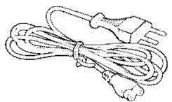
The configuration of the AC outlet and AC power supply cord differs according to area.
- Front Panel Controls and Their Functions 5
Protection Circuitry 5
Operation 6
- Troubleshooting Guide 7
- Maintenance 7
Before Use
Be sure to disconnect the mains cord before adjusting the voltage selector.
Use a minus (-) screwdriver to set the voltage selector (on the rear panel) to the voltage setting for the area in which the unit will be used.
(If the power supply in your area is 117V or 120V , set to the "127 V" position.)
Note that this unit will be seriously damaged if this setting is not made correctly. (There is no voltage selector for some countries; the correct voltage is already set.)
Technical Specifications (DIN 45 500)
■ AMPLIFIER SECTION
40 Hz~20 kHz continuous power output both channels driven 2 × 60W (8Ω)
1 kHz continuous power output both channels driven 2× 70W (8)
Total harmonic distortion rated power at 40 Hz~20 kHz 0.04% (8Ω) half power at 1 kHz 0.03% (8Ω)
Intermodulation distortion rated power at 60 Hz: 7 kHz=4:1, SMPTE, 8Ω 0.05%
Power bandwidth both channels driven, -3 dB 10 Hz~30 kHz (8Ω, 0.04%) Damping factor 50 (8Ω)
Input sensitivity and impedance
PHONO 2.5 mV/4.7kΩ
TUNER, CD/AUX 150 mV/22kΩ
TAPE 1, 2/EXT 150 mV/22kΩ
PHONO maximum input voltage (1 kHz, RMS) 150 mV S/N
rated power (8Ω)
PHONO 71 dB (IHF, A: 72 dB)
TUNER, CD/AUX, TAPE 1,2/EXT
90 dB (IHF, A: 98 dB)
Frequency response PHONO RIAA standard curve ± 0.8 dB (30 Hz~15 kHz) TUNER, CD/AUX, TAPE 1,2/EXT 5 Hz~90 kHz (-3 dB)
Tone controls BASS 50Hz, + 10dB -10dB TREBLE 20kHz, + 10dB -10dB Loudness control (volume at -30dB) 50Hz, + 9dB
Output voltage and impedance
REC OUT 150 mV
Channel balance, CD/AUX 250 Hz~6,300 Hz ±1 dB
Channel separation, AUX 1 kHz 45 dB
Headphones output level and impedance 560 mV/330Ω
Load impedance MAIN or REMOTE 4 16 MAIN and REMOTE 8 16
GENERAL
Power consumption 360W
Power supply For Australia AC 50 Hz/60 Hz,240V For continental Europe AC 50 Hz/60 Hz,220V For others AC 50 Hz/60 Hz,110V/127V/220V/240V
Dimensions (W× H× D) 430× 86× 240mm (16-15/16" × 3-3/8" × 9-7/16") Weight 5.3 kg (11.7 lb.)
Note:
Total harmonic distortion is measured by the digital spectrum analyzer (H.P. 3045 system).
Suggestions for Safety
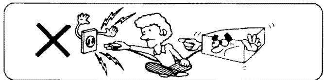
Use a standard electrical AC wall outlet
- Use from an AC power source of high voltage, such as for air conditioners, is very dangerous.
Be extremely careful not to make a connection to the electrical outlet for a large air conditioner or central-heating unit which uses high voltage, because there is the possibility of fire.
- A DC power source cannot be used.
Be sure to check the power source carefully, especially on a ship or other place where DC is used.
■ Connection and removal of the power cord plug
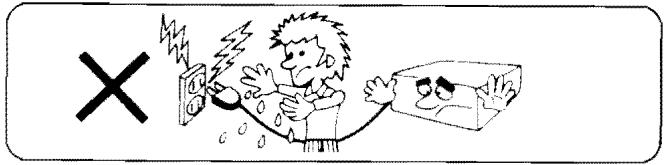
- Wet hands are dangerous.
A dangerous electric shock may result if the plug is touched by wet hands.
- Don't pull the power cord.
Always grasp the plug: never pull the cord itself.
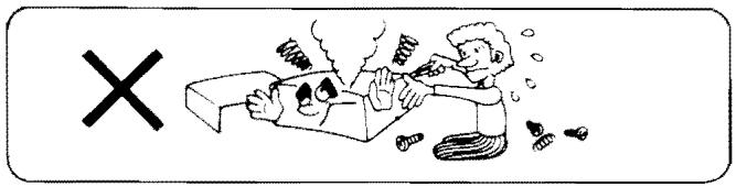
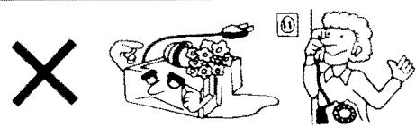
■ Never attempt to repair or reconstruct this unit
A serious electric shock might occur if this unit is repaired, disassembled or reconstructed by unauthorized persons, or if the internal parts are accidentally touched.
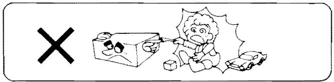
For families with children
Never permit children to put anything, especially metal, inside this unit. A serious electric shock or malfunction could occur if articles such as coins, needles, screwdrivers, etc. are inserted through the ventilation holes, etc. of this unit.
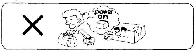
Turn off after use
If the unit is left for a long time with the power on, this will not only shorten its useful operation life, but may also cause other unexpected trouble.
If water is spilled on the unit
Be extremely careful if water is spilled on the unit, because a fire or serious electric shock might occur. Immediately disconnect the power cord plug, and consult with your dealer.
Place the unit where it will be well ventilated, and away from direct sunlight
Place this unit at least 10 cm (4") away from wall surfaces, etc., and away from direct sunlight. Be careful that curtains and similar materials do not obstruct the ventilation holes.
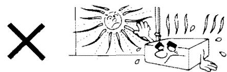
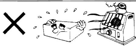
■ Keep the unit away from heaters, etc.
Heat can damage the external surfaces as well as internal circuits and components.
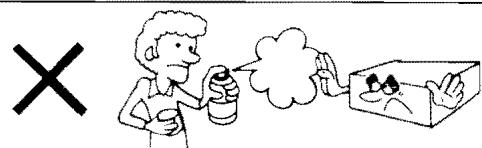
Avoid spray-type insecticides
Insecticides might cause cracks or "cloudiness" in the cabinet and plastic parts of this unit. The gas used in such sprays might, moreover, be ignited suddenly.
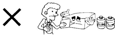
■ Never use alcohol or paint thinner
These and similar chemicals should never be used, because they may damage the finish.
If trouble occurs
If, during operation, the sound is interrupted or indicators no longer illuminate, or if abnormal odor or smoke is detected, immediately disconnect the power cord plug, and contact your dealer or an Authorized Service Center.
Connections
"TUNER" terminals
Connect a tuner.
"CD/AUX" terminals
Use these terminals to connect a compact disc player (digital audio disc), or tape deck (playback only).
"TAPE 1" terminals
Connect an audio tape deck.
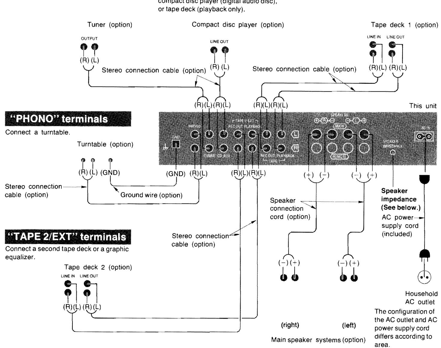
Speaker terminals ("SPEAKERS")
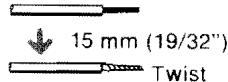
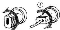
Connection of speaker wires
① Strip off the outer covering, and twist the center conductor.
② Turn completely to the left.
③ Insert wire and turn completely to the right. Pull wire to insure a proper connection.

②
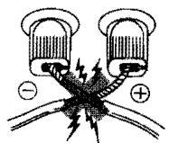
Note:
To prevent damage to circuitry, never short-circuit plus (+) and minus (-) speaker terminals.
Remote speaker terminals ("REMOTE")
For connection to a second pair of speakers.
Speaker impedance selector
Set to the position corresponding to the impedance of the speaker systems being used.
If a speaker system with an impedance value outside these ranges is connected, low output, protection circuit activation or amplifier damage may occur.
If either the main or the remote speaker systems are used:
4~6Ω (1→):
For speaker impedance of 4 6
8~16Ω(→I):
For speaker impedance of 8 16
If both main and remote speaker systems are used:
1) If the impedance of both systems is 16 ohms, set the speaker impedance selector to "16Ω".
2) If the impedance of both systems is 8 ohms, or one is 8 ohms and the other is 16 ohms, set the speaker impedance selector to "8Ω".
Note:
Be sure to make this setting before switching the power "on".
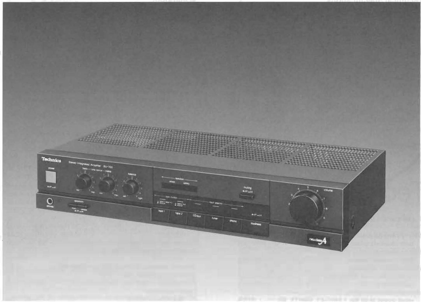
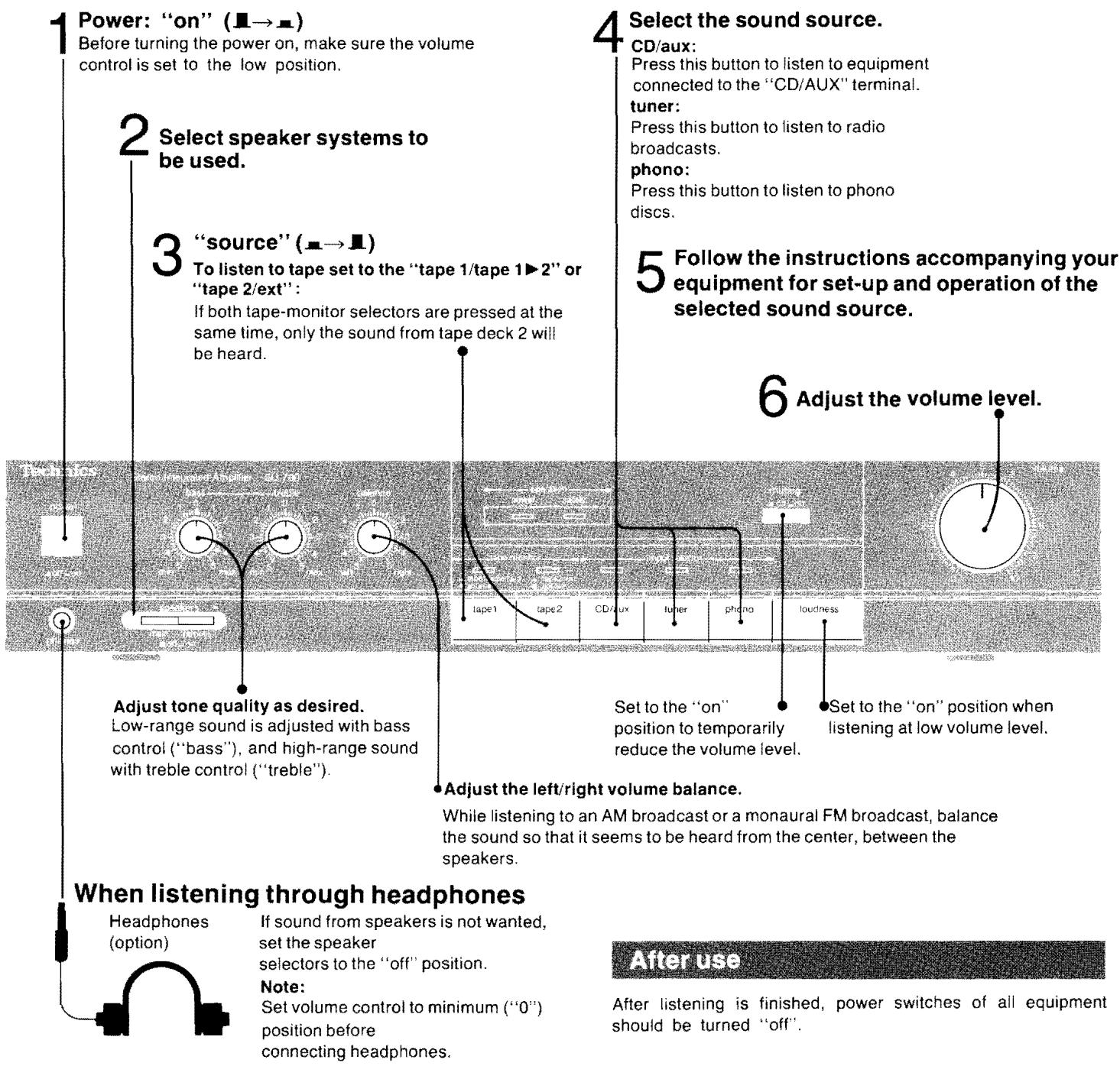
Front Panel Controls and Their Functions
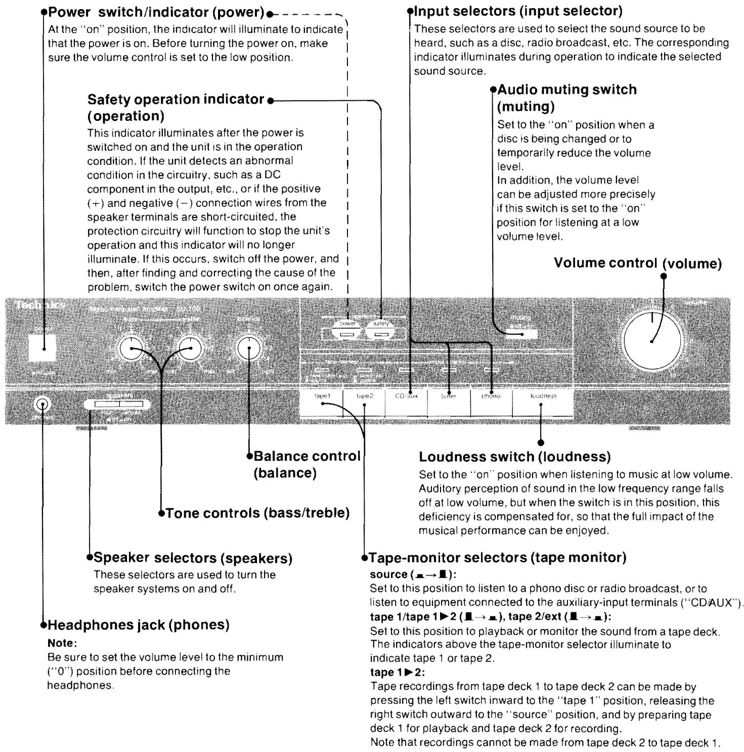
Protection Circuitry
The protection circuitry may have operated if either of the following conditions is noticed:
- No sound is heard when the power is turned on.
Sound stops during a performance.
The function of this circuitry is to prevent circuitry damage if, for example, the positive and negative speaker connection wires are "shorted", or if speaker systems with an impedance less than the indicated rated impedance of the amplifier are used.
If this occurs, follow the procedure outlined below:
- Turn off the power.
- Determine the cause of the problem and correct it.
- Turn on the power once again.
Note:
When the protection circuitry functions, the unit will not operate unless the power is first turned off and then on again.
Tape recording
- Follow above steps 1 through 6.
- Operation of tape deck connected to the "TAPE 1" and/or "TAPE 2/EXT" terminals.
- By using the controls on the tape deck, adjust the recording level. Then begin recording.
Tape-to-tape recording
By using two tape decks, tape-to-tape recording can be performed.
To record from tape deck 1 to 2 (Recording is not possible from 2 to 1):
1.Left tape monitor selector . "tape 1/tape 1 2 (I→R) Right tape-monitor selector . "source" ( )
2. Make the adjustment of the recording level by using the controls on the tape deck 2.
3. Begin the tape deck 1 (TAPE 1) for playback and the tape deck 2 (TAPE 2) for recording.
Troubleshooting Guide
Before requesting service for this unit, check the chart below for a possible cause of the problem you are experiencing. Some simple checks or a minor adjustment on your part may eliminate the problem and restore proper operation.
If you are in doubt about some of the check points, or if the remedies indicated in the chart do not solve the problem, refer to the directory of Authorized service centers (enclosed with this unit) to locate a convenient service center, or consult your Technics dealer for instructions.
| Problem | Probable cause(s) | Suggested remedy |
| Problems noted at all times |
| No sound is heard when the power is turned on. | Connections are incomplete or incorrect to the speaker systems, etc. | Check to be sure that all connection wires are correctly connected. |
| The incorrect input selector has been pressed. | Check to be sure that the correct selector is pressed. |
| The tape-monitor selectors are incorrectly set to the "tape" position. | Except for tape playback, set the tape-monitor selectors to the "source" position. |
| When listening to stereo sound, the sound of the various musical instruments is not heard from its correct position. | The positive (+) and negative (−) connections of the speaker connection wires are reversed. | Reconnect the speaker connection wires so that the positive and negative connections are correct. |
| When listening to stereo sound, the left and right sounds are reversed. | The left and right connections of the speaker connection wires are reversed. | Check the speaker connection wires and connect them correctly if necessary. |
| The left and right connections of the connec-tion wires connected to other equipment are reversed. | Check the connection wires to other equipment and connect them correctly if necessary. |
| A low-pitched noise ("hum" or "buzz") is heard. | The power cord or a fluorescent light, etc., is near the connection wires. | Try separating the amplifier from the electric appliance as far as possible.Reverse the connection of the power cord plug. |
| The connection of the ground wire is incorrect or incomplete. | Check to be sure that the grounding connection is correct. |
| Sound is not heard from the speaker system on one side. | The speaker connection wires are disconnected. | Check and correct the connections of the speaker connection wires. |
| The balance control of the amplifier is not set to the center position. | Set the mark on the balance control to the center position. |
| Sound stops during a performance, or no sound is heard when the power is turned on. | The protection circuitry has functioned because the positive and negative speaker connection wires are "shorted" or speaker systems with an impedance less than the indicated rated impedance of the amplefier are used. | Switch off the power, and, after determining and correcting the cause, turn on the power once again. |
Maintenance
To clean this unit, use a soft, dry cloth.
If the surfaces are extremely dirty, use a soft cloth, dipped into a soap-and-water solution or a weak detergent solution.
Wring the cloth well before wiping the unit.
Wipe once again with a soft, dry cloth.
Never use alcohol, paint thinner, benzine, nor a chemically treated cloth to clean this unit.
Such chemicals may damage the finish of your unit.
90 dB (1HF, A: 98 dB)
Respuestade freuencia TOCADISC. (PHONO) curva RIAA estandar ± 0,8 dB (30 Hz~15 kHz)
SINTON, CD/AUX., GRAB. 1, 2/EXT
(TUNER, CD/AUX, TAPE 1, 2/EXT) 5Hz 90kHz(-3dB)
Controles de tono
BAJOS (BASS) 50 Hz, +10 dB~ -10 dB
AGUDOS (TREBLE) 20kHz, + 10dB -10dB
90 dB (IHF, A: 98 dB)