
CTR34 - Electronic board DUCATI - Free user manual and instructions
Find the device manual for free CTR34 DUCATI in PDF.
User questions about CTR34 DUCATI
0 question about this device. Answer the ones you know or ask your own.
Ask a new question about this device
Download the instructions for your Electronic board in PDF format for free! Find your manual CTR34 - DUCATI and take your electronic device back in hand. On this page are published all the documents necessary for the use of your device. CTR34 by DUCATI.
USER MANUAL CTR34 DUCATI
The manufacturer reserves the right to modify or improve the product without prior notice. Any inaccuracies or errors found in this manual will be corrected in the next edition.
A Scope of the device 18
B Limits to use 18
C Installation 19
D Operation 19
D.1 Controls 19
D.2 Safety devices.. 19
D.3 Outputs. 19
D.4 Power supply. 20
D.5 Accessory inputs/outputs 20
D.6 Optical signals 20
D.7 Trimmers 21
D.8 Dip switches 21
D.9 Programming keys 21
D.10 Protection fuses 22
D.11 Technical features 22
D.12 Operation modes 23
D.13 Electrical and mechanical specifications 25
D.14 Electric connections 25
E Maintenance 28
F Conformity declaration 28
G Board programming 29
H General diagram 30
ENGLISH
A) - Scope of the device
The electronic board controls one or two low voltage motors that operate at 15Vdc or 24Vdc for the automation of a single or two-wing gate.
B) - Limits to use
Caution : Before operating the electronic unit make sure the following operations have been carried out.
Note 1 - Read carefully the whole technical documentation supplied.
Note 2 - The electronic unit must be installed by qualified personnel only. The installation engineer must have the necessary technical and professional qualification.
Note 3 - The mains power supply connected to the unit must be 230Vac + / - 10% .
Note 4 - The neutral (N) pole of the mains power supply must be unipotential to the ground.
Note 5 - All security norms for the installation of electric and electronic devices must be respected.
Note 6 - The mains power must be supplied with an efficient differential switch tested and calibrated in conformity with the applicable rules.
Note 7 - Before installing the electronic unit check the motors to which it will be connected. When the motors are connected to a suitable battery the torque they apply to the gate must respect the applicable rules and, in any case, it must be such that in case of collision no damage will be caused to persons, animals or objects.
Note 8 - The unit must be applied for the intended use only (see point A). All other use is to be considered improper and dangerous.
Note 9 - Before acceding to the electronic unit's box for any intervention check that the mains power has been cut off.
Note 10 - Do not access the unit with wet/damp hand or feet.
Note 11 - Do not expose the unit to weather (rain, snow, etc.)
Note 12 - Do not allow any children or unqualified persons to touch the unit.
Note 13 - The electronic unit must be placed in the box supplied.
Note 14 - The plastic material used for the box is not self-extinguishing. Therefore it must be installed in an well aired place far from any objects or elements that can cause fire.
Note 15 - The ordinary maintenance of electronic unit must be executed by qualified personnel every 6 months.
Caution: Failure to respect the above listed norms can cause damage to persons, animals or objects. The manufacturer can in no way be held responsible for such damage.
ENGLISH
C) - Installation
1) Unscrew the cover screws and lift the cover. Check that the electronic unit is in good order. In case of doubt do not install the unit and ask for the intervention of qualified personnel. The container's accessories (screws, round seal, cable glands) must not be left within the reach of children since they are a potential danger.
2) Check that the electronic unit is properly fixed to its box. If not, tighten all screws or provide the missing screws.
3) Place the unit near the gate so that the system connection wires' length is reduced to the minimum.
Caution: For the unit's correct operation the wires connected to it must not be longer than 10 metres.
4) For increased weather protection we recommend to place the unit under a roof or, even better, in an enclosure having two side walls. Wherever possible, it is advisable to install the unit at a minimum 1,5 mt level above the ground to keep it out of the reach of children.
5) Before proceeding to assembly place the container so that the side fitted with the cable glands is directed towards the ground.
Caution: Do not assemble the container on wood surfaces.
6) Lift the mobile portion of the connector and proceed to connect the unit wires as described in the following chapters.
Caution : The motors, battery, electric lock and blinker connection wires must have a 2,5 mm² minimum size.
D) - Operation
1) Definitions of Controls
Start
Input connected to a push-button placed outside the unit. It is employed to request the gate's opening or closure (for both wings). This input is usually connected to a key push-button.
Pedestrian Start
Input connected to a push-button placed outside the unit. It is employed to request the opening or closure of one wing only (pedestrian wing) to allow the passage of persons or animals.
2) Definitions of Safety devices
Stop
Input connected to a push-button or switch placed outside the unit. It is employed to cause the gate's immediate stop. This control must used in an emergency situation.
Photo-cell
Input connected to an optical barrier. It detects and signal the passage of persons or vehicles in the area crossed by the gate or in the nearby area.
Photoshop
Input connected to an optical barrier. It detects and signal the passage of persons or vehicles in the area crossed by the gate or in the nearby area.
3) Definitions of Outputs
Blinker
Lamp's on/off control. The lamp functions as a warning and optical signaller of potential danger for the gate's motion.
ENGLISH
Motor 1
Outputs for the opening/closure control of the motor which drives the first gate wing during the closing phase.
Motor 2
Outputs for the opening/closure control of the motor which drives the gate wing delayed during the closing phase. This wing is usually connected with an electric lock.
Electric lock
Impulse control for the electric lock release.
4) Definitions of Power Supply Inputs/Outputs
AC IN
12Vac or 20Vac Input for the electronic board power supply.
12Vcc or 24Vcc OUT (It depends on the position of the Jumper JP2)
Power supply output for the photo-cells and/or any other accessory devices.
BATT IN
Input for a 12Vdc or 24Vdc backup battery connection, it depends on the power supply selected. In case of 24Vdc battery connection, It's obligatory to remove the Jumper JP1. Attention: The electronic card isn't able to charge a 24Vdc battery, so it'll be necessary to connect a suitable external battery-charger.
5) Definitions of Accessory Inputs/Outputs
Aerial
Input for the connection of a radio receiving aerial. This input can only be used if a radio receiver card is connected to the unit.
2nd radio channel
Auxiliary control output. To be used only if a two-channel radio receiver card is connected to the unit.
6) Definitions of Optical Signals
DL1 - Programming led (red)
It is lit (together with the blinker) in the programming phase and during the gate's motion.
DL2 - Mains power led (green)
It is lit when the 12Vac or 20Vac voltage is present to the AC IN input.
DL3-Pedestrian start led (green)
It is lit when the pedestrian start control is operated.
DL4 - Start led (green)
It is lit when the start control is operated.
DL5 - Stop led (red)
It signals the gate's block state. The led goes off when the stop control is operated (emergency).
DL6 - Photo-cell led (yellow)
It signals the optical barrier's state. The led goes off when the photo-cell is covered by persons or vehicles
DL7 - Photostop led (yellow)
It signals the optical barrier's state. The led goes off when the photo-cell is covered by persons or vehicles
ENGLISH
7) Definitions of Trimmers
RV1 - Slow-down speed
It defines the gate's speed during the slow-down phase.
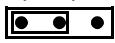
8) Definitions of Dip Switches and Jumpers (Selection of Programs)
Dip switch 1 (Attention: if you place the Dip switch 1 in ON, the state of the Dip switch 2 doesn't have any influence anymore) It chooses whether the unit will operate in the mode determined by dip-switch 2 or in condominium mode.
ON=Codominium OFF=No effect
Dip switch 2
It chooses whether the unit will operate in step-by-step mode or in automatic mode.
ON = Automatic OFF=Step by step
Dip switch 3
It enables the operation with a single-wing gate.
ON=Single wing OFF=Double wing
Dip switch 4
It enables or excludes the kickback (during the opening phase with closed gate) and extra-push (during the closure phase) procedures.
ON= Kickback enabled OFF=No effect
Dip switch 5 (Important: if you place the Dip switch 5 in ON, the Dip switch 3 must be positioned obligatorily in OFF)
It enables or excludes the delay between the wings' starts
ON=0secDelay OFF Delayenabled
Jumper JP1
When it's removed, it disconnects the 13,5Vdc battery-charger built in on the electronic card. In case of motors that operate at 24Vdc, you must remove the JP1 Jumper so it's possible to connect a 24Vdc battery equipped with external battery-charger.
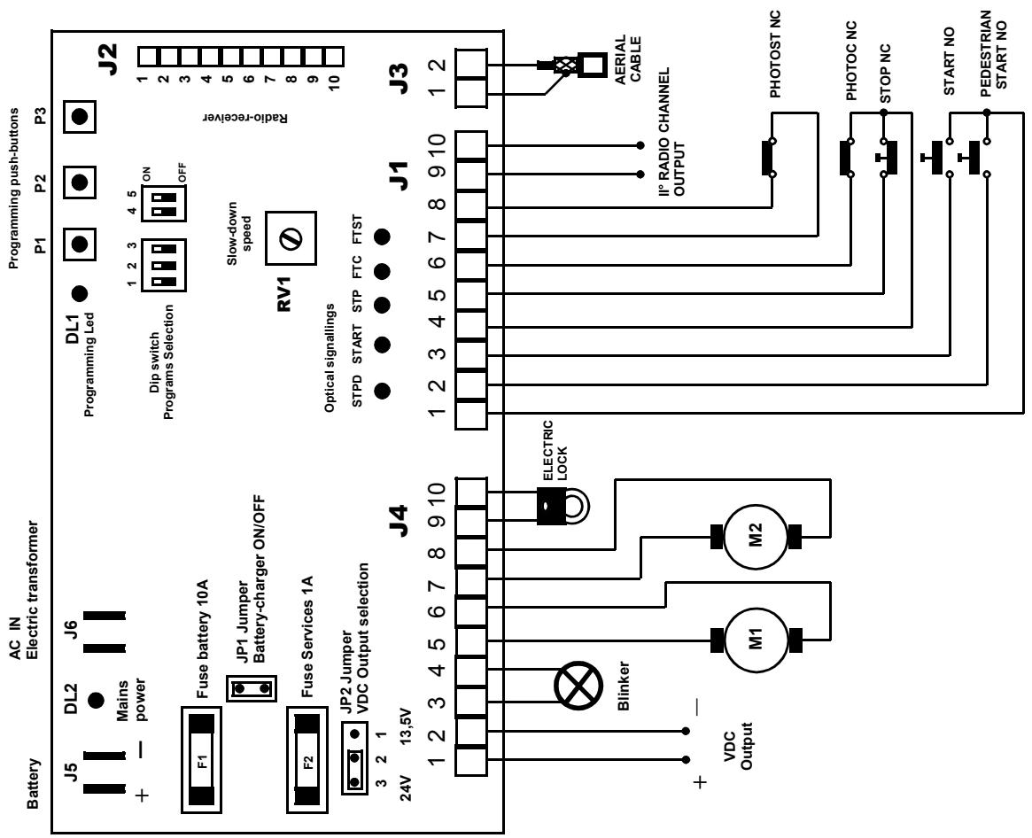
Jumper JP2
It selects the power supply voltage on the output terminals 1 and 2 of J4. You can select 13,5Vdc or 24Vdc.

1 2 3


1 2 3
9) Definitions of Programming Keys
P1 - Allows to insert/cancel the radio-command codes in the memory
P2 - Allows to set the motors' work time and the M2 motor's closing delay time
P3 - Allows to set the pause time
ENGLISH
10) Definitions of Protection Fuses
F1-Battery fuse (10A)
It disconnects the backup battery from the electronic card in case of short-circuit or electric current consumption anomalies.
F2 - Services fuse (0,8A)
It protects the electronic unit in case of short circuits or overcurrents on photo-cells or any other accessory devices connected to the card.
11) Technical features
Power supply
The electric power is supplied to the electronic card and the motors by means of an electric transformer fitted with a protection fuse. The appliance may be connected to an optional backup battery (12Vdc or 24Vdc) for the automation system to work in case of absence of power supply. If the JP1 Jumper is inserted, the electronic card is able to charge a 12Vdc battery. The electronic card isn't able to charge a 24Vdc battery. If you connect a 24Vdc battery, it is obligatory to remove the JP1 Jumper and connect an external and suitable battery-charger.
Radioreceiver
The electronic unit contains a two-channel radio receiver allowing remote control of the gate by means of the radio transmitter. The radio receiver channel 1 acts as Start control and channel 2 acts as Pedestrian start. The radio receiver operates with a self-learning logic and can store up to 50 different codes from the remote controls. Each code may be addressed on the desired channel (start or pedestrian start). The memory contents is preserved in absence of power supply. The memory contents may be erased (total cancellation). In alternative the electronic unit is pre-set for the optional connection of an accessory radio receiver card. The channel 1 of the radio receiver card ends with a non-polarized electric contact (relay) directly connected to the start input. The channel 2 of the radio receiver card ends with a non-polarized electric contact (relay) directly connected to the 2nd radio channel output.
Work time
The motors' work time is controlled by two independent digital timers. If any command interrupts the wing's travel before its end, the Timer stops and the elapsed time is stored in memory. Therefore the unit can determine, with a fair approximation, the partial working time necessary to the wing to end its travel. For the automation system to work properly the work time value to be set (see page 29) must be slightly (approx. 5 sec.) above the wing's actual work time. In this way the motor will stop even if the AMPEROMETRIC STOP control has not operated. We recommend to adjust the work time so that the wing starts to slow down at min. 50~cm from the end of its travel. The stop of the wing depends by the current consumed by the motor (Torque). During the normal speed phase, when the motor's current reaches the self-learned value, the gate stops (both wings) in opening and then it reverses its motion for approx. 2 sec., while during the closure phase, the gate stops and reverses its motion after approx. 1,5 sec. During the slowing-down phase the AMPEROMETRIC STOP acts as a Limit switch. After the electric power is supplied to the electronic card (at installation), or after one absence of power supply, when the Start push-button is pressed for the first time the gate performs a slowed-down opening cycle. This feature guarantees maximum safety of operation.
Warning : In case of absence of power supply the stored position will be lost.
Kickback / extra-push
This procedure can be enabled or excluded. It is usually employed to help the electric lock insertion and release during bad weather conditions (wind, ice, etc.). The "kickback" procedure consists of a logic sequence operating the electric lock during a short closure phase (approx 1 sec.) with the gate closed. The electric lock is released only after the wing has started its opening motion. The "extra-push" procedure is enabled only during the closing slow-down phase near at the end of the wings' travel. It consists of a short acceleration of both wings (approx. 1 sec.) to help the electric lock's insertion.
ENGLISH
Blinker
The electronic card supplies an on/off control (flashing light) to the lamp. The logic of the blinking allows displaying the gate's operating.
Quick flashing light : it signals the opening phase
Slow flashing light : it signals the closing phase
Fixed light : it signals that the gate is blocked in wait that the obstacle that covers the photocell or photostop to be removed.
The device supplies an on/off control (flashing light) to the lamp for approx. 1 sec. before the motors start (pre-alarm).
Important : In case of absence of power supply, with the backup Battery connected to the card, the blinker flashes every 4 sec. (in opening and closing cycle).
M1 delay at opening
The unit causes a fixed delay of approx. 2 seconds between the first wing's (M2) and the second wing's (M1) start during the gate's opening phase.
This delay is imposed irrespective of the position from which the gate starts to open. This delay may be cancelled by setting the dip switch 5 =ON.
12) Operation modes
Introduction
The electronic unit contains a micro-processor to control the gate's operation modes. These are the four main operation phases:
Phase preceding the gate's motion
Gate's fast motion phase
Gate's slow motion phase
Gate's pause phase (open gate)
The unit can function in three modes:
Step by step - This mode is enabled by setting the dip switches 1=OFF 2=OFF
Automatic - This mode is enabled by setting the dip switches 1 = OFF 2 = ON
Condominium- This mode is enabled by setting the dip switches 1=ON 2= No effect
The Condominium mode is the priority operation mode. If more than one modes are selected the priority mode will be enabled.
Notice: The operation logic setting (dip switch), the work time programming and the pause time programming must be carried out only if the cycle is concluded or before it starts (with closed gate).
The opening and closure cycles are enabled by a Start or Pedestrian start control.
Important : Whatever logic has been selected, the first Start command after the power is supplied to the electronic card will always cause the start of an opening cycle
"Step-by-step" mode
After the power is supplied to the electronic card the first start command determines an opening cycle. During the slow-down phase, at the end of the two work times or after the AMPEROMETRIC STOP has operated for both motors, the gate stops. The operating cycle is completed (blinker off) and the system waits for a new start command to determine the closing cycle. If a start command is supplied when the end of travel has not been reached yet the gate stops. A new start command will cause the reversal of the motion.
ENGLISH
"Automatic" mode
After the power is supplied to the electronic card the first start command determines an opening cycle. During the slow-down phase, at the end of the two work times or after the AMPEROMETRIC STOP has operated for both motors, the gate stops. The pause period starts (blinker off). At the end of the pause period the gate closes automatically. The operating cycle is complete only when the closing motion has ended. If a start command is supplied before the end of travel is reached the gate stops. A new start command will cause the gate to reverse its motion. If a start command is supplied during the pause period the operating cycle is interrupted and the gate does not close automatically. A further start command will determine a closing cycle.
"Condominium" mode
After the power is supplied to the electronic card the first start command determines an opening cycle. During the slow-down phase, at the end of the two work times or after the AMPEROMETRIC STOP has operated for both motors, the gate stops. The pause period starts (blinker off). At the end of the pause period the gate closes automatically. The operating cycle is complete only when the closing motion has ended. If a start command is supplied while the gate opens, the command will have no effect. If a start command is supplied while the gate closes, the gate will stop and reverse its motion after approx. 1.5 sec. If a start command is supplied during the pause period, the period will be reset and the automatic closure will start later. Important : If the gate opening is controlled by a clock the "condominium" mode must be enabled.
"Single wing" mode
This mode is employed with single-wing gates. When enabled, it drives the motor M2 only. The operating modes described above remain unchanged. When the "single-wing" mode is selected the dip switch 3=ON must be set.
Note : At the beginning of each opening cycle, with the gate closed, the electric lock can operate in 2 modes :
1) If dip switch 4=OFF the electric lock operates a split of second (0,8 sec) before the first wing (M2) starts, and stops operating a split of second (0,4 sec) after the wing's start.
2) if dip switch 4=ON the electric lock operates for a short time (approx. 1 sec.) during the wings' closure, and stops operating after that the M2 wing starts the opening. The "kickback" procedure is usually employed to help the electric lock's release during bad weather.
In any operation mode, the safety devices causes the following effects :
Stop : If the stop command is enabled no cycles can start and the start command will have no effect. If a stop command is supplied during motion, the gate will immediately stop e interrupt its operating cycle. This condition will continue until the stop command is on. A start command following a stop command always determines an opening cycle. A stop command supplied during the pause period interrupts the operating cycle. A start command subsequently supplied will start a closure cycle.
Photo-cell : This device has effect only during the closure phase or in the pause period. If an obstacle covers the photo-cell during the closure phase , the gate stops and reverses its motion after approx. 1,5 sec. If an obstacle covers the photo-cell during the pause period this last one is reset and the automatic closure is therefore delayed.
Photostop : If an obstacle covers the photo-cell during the gate's motion (opening or closure), or during the period preceding the operating cycle's start, then the gate is temporarily stopped, until the obstacle is not removed. The blinker will light with a fixed light to signal the irregular condition. When the obstacle is removed and the photocell is freed, an opening cycle will start. This does
ENGLISH
Pedestrian start: The pedestrian start command operates in the same way as the other start command, but in this case only the (M2) wing fitted with the electric lock will be opened or closed. The pedestrian start command has no effect during a start cycle and up to the end of the closing phase (closed gate). During a pedestrian start cycle the start command is always active and causes the start of an opening cycle for both wings.
13) Electrical and mechanical specifications
Dimensions and weight : 186 x 283 x 112 mm - 2,3 Kg
Power supply transformer : 230 / 12Vac-20Vac - 100VA
Battery-charger capacity : 13,5Vdc - 0,5 A
Optional battery capacity : 12Vdc or 24Vdc – 7 Ah
Blinker power supply : 15Vdc or 24Vdc - 15 W max
Relays contacts characteristics : 14Vdc 15 A max
Electric lock power supply : 15Vdc or 24Vdc - 15 W max
Motor power supply : 15Vdc or 24Vdc - 100 W max
Radio receiver power supply : 13,5Vdc - 2 W max
Accessories power supply : 13,5Vdc or 24Vdc - 3 W max
Operating temperature range: 0 to +60 °C
2^nd radio channel relay contact characteristic: 24Vac 0,5 A max
Motors' work time : programmable, 1 to 120 sec.
Pause time : programmable, 1 to 120 sec.
2^nd wing closing delay : programmable, 0 to 25 sec.
Amperometric Stop : Automatic
Caution : The unit must be not switched on if the connected loads or the power supply exceed the a.m. limits. Failure to observe this precaution can result in damage to persons, animals or objects for which the manufacturer cannot be held responsible.
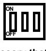
14) Electric connections
6 electric connectors are fitted to the card :
1) J1 10-pole removable terminal board for the connection of the commands and safety devices
2) J2 10-pole connector for the optional connection of a radio receiver card
3) J3 2-pole Terminal board for the connection of the aerial cable
4) J4 10-pole removable terminal board for the connection of the power devices
5) J5 (FS3,FS4) 2 Faston for the connection of a Backup battery
6) J6 (FS1,FS2) 2 Faston for connection of the power supply transformer
ENGLISH
Terminal board J1
Terminal1 - Common terminal for all electric contacts of commands
Terminal2 - Pedestrian start push-button's normally open electric contact
Terminal3 - Start push-button's normally open electric contact
Terminal4 - Common terminal for all electric contacts of stop push-button and photo-cell
Terminal5 - Emergency push-button's normally closed electric contact (stop)
Terminal6 - Photo-cell's normally closed electric contact
Terminal7 - Common terminal for the electric contact of photostop
Terminal8 - Photoelectric cell's normally closed electric contact (photostop)
Terminal9 - 2nd radio-channel's normally open electric contact (output)
Terminal10 - 2nd radio-channel's normally open electric contact (output)
Important: The normally closed inputs not in use must be fitted with jumpers
Connector J2
Terminal1 - Normally open electric contact connected to the start
Terminal2 – Common of the normally open electric contact connected to the start
Terminal3 - Normally open electric contact connected to the 2nd radio-channel output
Terminal4 - Normally open electric contact connected to the 2nd radio-channel output
Terminal5 - Power supply negative (common)
Terminal6 - Power supply positive
Terminal7 - Power supply positive
Terminal8 - Power supply negative (common)
Terminal9 - Aerial input (shield)
Terminal10 - Aerial input (signal)
Terminal board J3
Terminal1 - Aerial cable connection (shield) for radio receiver card
Terminal2 - Aerial cable connection (signal) for radio receiver card
Terminal board J4
Terminal1 - Power supply positive for photo-cells or other devices
Terminal2 - Power supply negative for photo-cells or other devices (common)
Terminal3 - Power supply positive for blinker
Terminal4 - Power supply negative for blinker (common)
Terminal5 - Motor M2 power supply
Terminal6 - Motor M2 power supply
Terminal7 - Motor M1 power supply
Terminal8 - Motor M1 power supply
Terminal9 - Power supply positive for electric lock
Terminal10 - Power supply negative for electric lock (common)
ENGLISH
Connector J5
FS3 Faston - Backup battery's positive pole connection
FS4 Faston - Backup battery's negative pole connection
Connector J2
FS1 Faston - Power supply from the electric transformer
FS2 Faston - Power supply from the electric transformer
Connection of the devices
Motor 1 - Terminals 7 and 8 on J4
Motor 2 - Terminals 5 and 6 on J4
Blinker - Terminals 3 and 4 on J4
Electric lock - Terminals 9 e 10 on J4
Photo-cells power supply - Terminals 1 and 2 on J4
NC photo-cell contact - Terminals 6 and 4 on J1
NC stop push-button - Terminals 5 and 4 on J1
NC photosop contact - Terminals 7 and 8 on J1
NO start push-button - Terminals 1 and 3 on J1
NO pedestrian start push-button - Terminals 1 and 2 on J1
Aerial - Terminals 1 and 2 on J3
Important: Before starting the gate check the following conditions :
a) connections to the electronic card
b) electric contacts' switching
c) state of the protection fuses
d) leds' correct operation.
ENGLISH
E) MAINTENANCE
Warning : The maintenance of the device must be effected only and exclusively by a specialized technician authorized from the Manufacturer. Any operation of maintenance or control of the device must be effected in absence of power supply.
Ordinary maintenance: Every time that it is necessary and however every 6 months is recommended to verify the device operation. Extraordinary maintenance: In case of failure, remove the device and send it for repair to the manufacturer laboratory or to authorized laboratory. The Manufacturer is not responsible for missing observance of rules above described.
F) CONFORMITY DECLARATION (To EMC directive EN45014 and ISO guide 22)
Company name and registered office :
Description of the appliance : Electronic board for the control of 1 or 2 low voltage motor for gate automation.
Model: CTR34
Reference rules applied : EN 50081-1, EN 50082-1, EN 55014
Basic rules applied: EN 61000-3-2, EN 61000-3-3, EN 61000-4-4, EN 61000-4-2, ENV 50140, EN 55104, EN 61000-4-11, EN 61000-4-5
Test laboratory: Comutec
Outcome: Positive
The manufacturer declares that the above listed products comply to the norms on electromagnetic compatibility provided for by directives 89/336/EEC, 92/31/EEC, 93/68/EEC.
Date,20-05-2000
ENGLISH
G) Programming the board

123

45
Step-by-step logic
Set the dip switches 1 and 2 to OFF
The state of the other dip switches has no effect

123

45
Condominium logic
Set the dip switch 1 to ON
The state of the other dip switches has no effect

123

45
Automatic logic
Set the dip switch 1 to OFF
Set the dip switch 2 to ON
The state of the other dip switches has no effect

123

45
Kickback / extra-push logic
Set the dip switch 4 to ON
The state of the other dip switches has no effect

123

45
Single wing logic
Set the dip switch 3 to ON
The state of the other dip switches has no effect
123

45
2nd wing delay reset (zero delay)
Set the dip switch 5 to ON
The dip switch 3 must be positioned obligatorily in OFF
The state of the other dip switches has no effect
Attention: before proceeding with the programming of the card, it is necessary that all the inputs are connected correctly (see chapters D1 and D2).
Radio-command codes self-learning: Press the P1 key once to insert a "Start" code; press the P1 push-button twice to insert a "Pedestrian Start" code. Each time the push-button is pressed, the led DL1 flashes in acknowledgement. Subsequent pressures of the P1 key must be spaced by 1 sec. minimum periods. When the led is lit with a fixed light transmit the code to be learn by means of the radio-command.
Erasing all stored codes: Press push-button P1 until the led DL1 goes off (about 10 seconds).
Setting the work time: Make sure the gate is completely closed. If not, position it manually. Press push-button P2 for about 3 seconds (the led DL1 will light with a fixed light) until the gate starts opening at a reduced speed. During this phase adjust the speed by means of the trimmer RV1 to obtain the desired slow-down. After 3 seconds from the complete opening, push the P2 key again and wait for the led DL1 and the blinker to go on with a fixed light. Then push the P2 key repeatedly (6 times) to program the following operations :
1) motor M1 start
2) motor M2 start (delayed)
3) motor M1 slow-down start
4) motor M2 slow-down start
5) motor M1 stop (after 5 seconds from the end of the run)
6) motor M2 stop (after 5 seconds from the end of the run) - end of programming
Setting the pause time: Press push-button P3 until the led DL1 lights. Let the desired pause time pass, then press push-button P3 again.
ENGLISH
General diagram