
CTR29 - Electronic board DUCATI - Free user manual and instructions
Find the device manual for free CTR29 DUCATI in PDF.
| Product Type | Electronic board for controlling single-phase asynchronous motor 230 Vac, intended for automation of rolling shutters or awnings |
| Brand | DUCATI |
| Model | CTR29 |
| Dimensions (W x H x D) | 88 x 127 x 58 mm |
| Weight | 0.3 kg |
| Power Supply | 230 Vac +/- 10%, 50/60 Hz |
| Operating Temperature | 0 °C to +60 °C |
| Max Motor Power | 1 HP under 230 Vac |
| Built-in Radio Receiver | Frequency 433.92 MHz, sensitivity -102 dBm, self-learning up to 120 codes |
| Operating Time Programming | From 1 to 250 seconds, memorized even after power cut |
| Operating Logics | Step-by-step, manual (presence), cyclic - selectable by jumper JP1 |
| Protection | Mains fuse 5A (F1) |
| Compliance | Directives EMC 89/336/EEC, 92/31/EEC, 93/68/EEC; standards EN 50081-1, EN 50082-1, EN 55014 |
| Manufacturer | Leb electronics s.r.l., Via Valle Maria, 55/a, 46040 Casalmoro (MN) Italy |
| Maintenance | Ordinary every 6 months by qualified personnel; always de-energized |
| Repairability | In case of failure, send to manufacturer or approved laboratory |
| Supplied Accessories | Protection box, connectors J1 (5-pin) and J2 (5-pin) |
Frequently Asked Questions - CTR29 DUCATI
User questions about CTR29 DUCATI
0 question about this device. Answer the ones you know or ask your own.
Ask a new question about this device
Download the instructions for your Electronic board in PDF format for free! Find your manual CTR29 - DUCATI and take your electronic device back in hand. On this page are published all the documents necessary for the use of your device. CTR29 by DUCATI.
USER MANUAL CTR29 DUCATI
CTR29
MANUALE D'ISTRUZIONI
INSTRUCTIONS MANUAL
MANUEL D'EMPLOI
ITALIANO 3
ENGLISH 15
FRANCAIS 27
The manufacturer reserves the right to modify or improve the product without prior notice. Any inaccuracies or errors found in this manual will be corrected in the next edition.
D.7 Programs selection.... 19
D.8 Protection fuse.... 20
D.9 Technical features.... 20
D.10 Operation modes.... 21
D.11 Electrical and mechanical specifications... 22
D.12 Electric connections.... 22
E MAINTENANCE.... 24
F CONFORMITY DECLARATION.... 24
G BOARD PROGRAMMING.... 25
H GENERAL DIAGRAM.... 26
A) SCOPE OF THE DEVICE
Electronic board controlling one 230 Vac single-phase asynchronous motor for the automation of one roller shutter or one sun awning.
B) LIMITS TO USE
Caution : Before operating the electronic unit make sure the following operations have been carried out.
Note 1 - Read carefully the whole technical documentation supplied.
Note 2 - The electronic unit must be installed by qualified personnel only. The installation engineer must have the necessary technical and professional qualification.
Note 3 - The mains power supply connected to the unit must be 230 Vac +/- 10%.
Note 4 - The neutral (N) pole of the mains power supply must be unipotential to the ground.
Note 5 - All security norms for the installation of electric and electronic devices must be respected.
Note 6 - The mains power must be supplied with an efficient differential switch tested and calibrated in conformity with the applicable rules.
Note 7 - Before installing the electronic unit check the motor to which it will be connected. When the motor is connected to the mains power the torque it apply to the roller shutter must respect the applicable rules and, in any case, it must be such that in case of collision no damage will be caused to persons, animals or objects.
Note 8 - The unit must be applied for the intended use only (see point A). All other use is to be considered improper and dangerous
Note 9 - Before acceding to the electronic unit's box for any intervention check that the mains power has been cut off.
Note 10 - Do not access the unit with wet/damp hand or feet.
Note 11 - Do not expose the unit to weather (rain, snow, etc.)
Note 12 - Do not allow any children or unqualified persons to touch the unit.
Note 13 - The electronic unit must be placed in the box supplied.
Note 14 - The plastic material used for the box is not self-extinguishing. Therefore it must be installed in an well aired place far from any objects or elements that can cause fire.
Note 15 - The ordinary maintenance of electronic unit must be executed by qualified personnel every 6 months.
Caution: Failure to respect the above listed norms can cause damage to persons, animals or objects. The manufacturer can in no way be held responsible for such damage.
C) INSTALLATION
1) Unscrew the cover screws and lift the cover. Check that the electronic unit is in good order. In case of doubt do not install the unit and ask for the intervention of qualified personnel. The container's accessories (screws, round seal, cable glands) must not be left within the reach of children since they are a potential danger.
2) Check that the electronic unit is properly fixed to its box. If not, tighten all screws or provide the missing screws.
3) Place the unit near the roller shutter so that the system connection wires' length is reduced to the minimum.
Caution: For the unit's correct operation the wires connected to it must not be longer than 10 metres.
4) For increased weather protection we recommend to place the unit under a roof or, even better, in an enclosure having two side walls. Wherever possible, it is advisable to install the unit at a minimum 1,5 mt level above the ground to keep it out of the reach of children.
5) Before proceeding to assembly place the container so that the side fitted with the cable glands is directed towards the ground.
Caution : Do not assemble the container on wood surfaces.
6) Proceed to connect the unit wires as described in the following chapters.
D) OPERATION
1) DEFINITIONS OF CONTROLS
Opening Start
Input connected to a push-button placed outside the unit. It is employed to request the opening of the roller shutter. A N.O. push-button is usually connected to this input.
Closing Start
Input connected to a push-button placed outside the unit. It is employed to request the closure of the roller shutter. A N.O. push-button is usually connected to this input.
2) DEFINITIONS OF OUTPUTS
Motor 1
Outputs for the opening/closure control of the motor which drives the roller shutter.
3) DEFINITIONS OF POWER SUPPLY INPUTS
230 Vac mains power
Input for the electronic board power supply.
4) DEFINITIONS OF INPUTS
Aerial
Input for the connection of a radio receiving aerial.
5) DEFINITIONS OF OPTICAL SIGNALS
LD1 - Power supply led (red)
It is lit when the electronic card power supply is present.
6) DEFINITIONS OF TIMERS
Work time
It defines the motor's work time during the opening or closure phases.
7) DEFINITIONS OF JUMPERS (SELECTION OF PROGRAMS)
JP1 jumper
It determines whether the unit will operate in step-by-step, manual or cyclical mode.
8) DEFINITION OF PROTECTION FUSE
F1 - Mains power fuse (5A)
It disconnects the electronic unit from the power supply mains in case of short-circuit or electric current consumption anomalies.
9) TECHNICAL FEATURES
Radioreceiver
The electronic unit contains a two-channel radio receiver allowing remote control of the roller shutter by means of the radio transmitter. The radio receiver channel 1 acts as Opening start, whereas channel 2 acts as Closing start. The radio receiver operates with a self-learning logic and can store up to 120 different codes from the radio-commands. Each code may be addressed on the desired channel (opening start or closing start). The memory contents is preserved in absence of power supply. The memory contents may be erased (total cancellation).
Work time
The motor's work time is controlled by one digital timer. For the automation system to work properly the operating time value to be set must be slightly (min. 2 sec.) above the roller shutter's actual work time. If any command interrupts the roller shutter's travel before its end, the Timer stops and the elapsed time is stored in memory. Therefore the unit can determine, with a fair approximation, the partial working time necessary to the roller shutter to end its travel. In case of limit switch lack, thanks to this feature it is possible to avoid that the motor works for a long time after the end of the roller shutter's travel, thus reducing overheating to the minimum.
Warning : In case of absence of power supply the stored position will be lost.
10) OPERATION MODES
Introduction
The electronic unit contains a micro-processor to control the roller shutter's operation modes.
These are the main operation modes :
"Step-by-step" mode (JP1 jumper = not inserted)
When the roller shutter is closed, the opening start command determines an opening cycle. At the end of the work time, the roller shutter stops. The operating cycle is completed and the system waits for a closing start command. If a opening start or closing start command is supplied when the end of travel has not been reached yet the roller shutter stops.
Manual (JP1 jumper = inserted between 3 and 2)
The roller shutter move until the (opening or closure) push-button is pressed.
Note : The opening start and closing start commands can be supplied by the two push-buttons of radio-command.
"Cyclical" mode (JP1 jumper = inserted between 1 and 2)
In cyclical mode the difference between the opening start and closing start commands is cancelled and both commands have the same function. The operation is controlled by a single start command. In cyclical mode the “step-by-step” operation logic remains unchanged.
Notice: The operation logic setting (jumper) and the work time programming must be carried out only if the cycle is concluded or before it starts (with closed roller shutter).
11) ELECTRICAL AND MECHANICAL SPECIFICATIONS
Dimensions and weight : 88 x 127 x 58 mm - 0,3 Kg
Mains power supply : 230 Vac +/- 10%
Operating temperature range : 0 to +60 °C
Single-phase motor power supply : 230 Vac 1 HP max
Motor's work time : programmable, 1 to 250 sec.
Operating frequency : 433,92 MHz
Radio receiver RF sensitivity : approx. -102 dBm
Caution : The unit must be not switched on if the connected loads or the power supply exceed the a.m. limits. Failure to observe this precaution can result in damage to persons, animals or objects for which the manufacturer cannot be held responsible.
12) ELECTRIC CONNECTIONS
2 electric connectors are fitted to the card :
a) J1 5-pole Terminal board for the connection of the devices operating with 230 Vac mains power supply (motor and mains cable).
b) J2 5-pole Terminal board for the connection of the devices operating at low voltage (commands and aerial).
TERMINAL BOARD J1
Terminal 1 - 230 Vac mains power supply phase
Terminal 2 - 230 Vac mains power supply neutral
Warning: The power supply voltage polarities must be carefully observed.
Terminal 3 - 230 Vac motor M1 power supply common
Terminal 4 - 230 Vac motor M1 power supply phase (opening)
Terminal 5 - 230 Vac motor M1 power supply phase (closure)
Note: connect the capacitor of the motor M1 between terminals 4 and 5
TERMINAL BOARD J2
Terminal 1 – Opening start push-button's normally open electric contact
Terminal 2 – Closing start push-button's normally open electric contact
Terminal 3 – Common terminal for all electric contacts of commands
Terminal 4 - Aerial input (signal)
Terminal 5 – Aerial input (shield)
CONNECTION OF THE DEVICES
230 Vac mains power supply cable and ground – Terminals 1 and 2 on J1
Warning: The cable's ground pole must be connected to a good ground reference in the roller shutter's nearby area.
Motor 1 – Terminals 3, 4 and 5 on J1
Aerial – Terminals 4 and 5 on J2
NO Opening start push-button – Terminals 1 and 3 on J2
NO Closing start push-button – Terminals 2 and 3 on J2
Important: Before starting the roller shutter check all connections to the electronic card. Check also the electric contacts' switching.
E) MAINTENANCE
Warning : The maintenance of the device must be effected only and exclusively by a specialized technician authorized from the Manufacturer. Any operation of maintenance or control of the device must be effected in absence of power supply.
Ordinary maintenance: Every time that it is necessary and however every 6 months is recommended to verify the device operation.
Extraordinary maintenance: In case of failure, remove the device and send it for repair to the manufacturer laboratory or to authorized laboratory.
The Manufacturer is not responsible for missing observance of rules above described.
F) CONFORMITY DECLARATION (To EMC directive EN45014 and ISO guide 22).
Company name and registered office :
Leb electronics s.r.l.
Via Valle Maria, 55/a
46040 Casalmoro (MN) - Italia
Description of the appliance:
Electronic board for the control of one 230 Vac single-phase asynchronous motor for roller shutter automation.
Model : CTR29.01
Reference rules applied : EN 50081-1, EN 50082-1, EN 55014
Basic rules applied : EN 61000-3-2, EN 61000-3-3, EN 61000-4-4, EN 61000-4-2, ENV 50140
Test laboratory : Intek s.p.a.
Outcome : Positive
The manufacturer declares that the above listed products comply to the norms on electromagnetic compatibility provided for by directives 89/336/EEC, 92/31/EEC, 93/68/EEC.
Casalmoro, 01-01-2000
G) PROGRAMMING THE BOARD
Step-by-step logic
JP1

1 2 3
jumper not inserted
Cyclical mode
JP1

1 2 3
jumper inserted between 1 and 2 terminals
Manual logic
JP1

1 2 3
jumper inserted between 3 and 2 terminals
Radio-command codes self-learning : Press the P1 push-button once to insert a "Opening Start" code; press the P1 push-button twice to insert a "Closing Start" code. Each time the push-button is pressed, the led DL1 flashes in acknowledgement. Subsequent pressures of the P1 push-button must be spaced by 1 sec. minimum periods. When the led is lit with a fixed light transmit the code to be learn by means of the radio-command.
Erasing all stored codes : Press push-button P1 until the led DL1 goes off (about 10 seconds).
Setting the work time : Press the Closing start push-button or the corresponding push-button on the radio-command until the roller shutter is completely closed. Press push-button P1 for about 3 seconds (the led will light with a fixed light) until the roller shutter starts to open. When it is completely open press push-button P1 again. The roller shutter will stop and the led will go off.
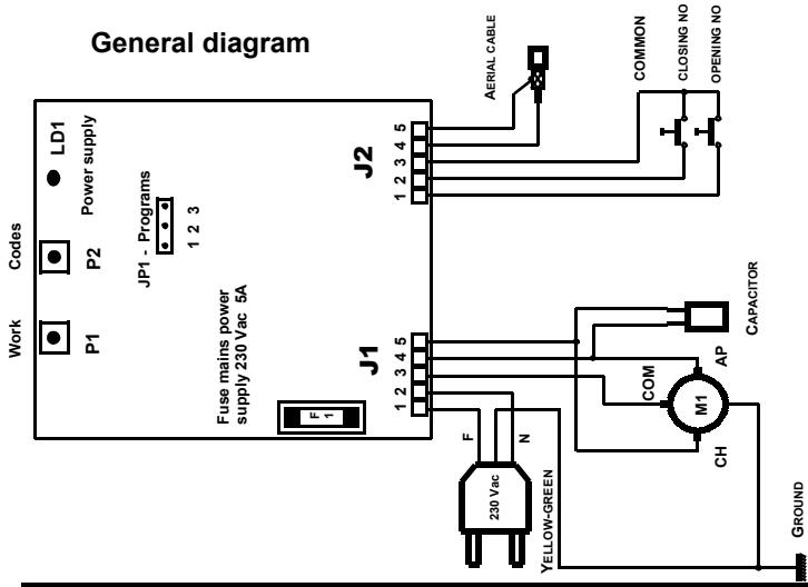
TABLE GENERALE
A EMPLOI DE LE TABLEAU ÉLECTRONIQUE 28
F DÉCLARATION DE CONFORMITÉ 36
G PROGRAMMATION DE LA CARTE ÉLECTRONIQUE 37
H SCHÉMA GÉNÉRAL 38