1198 - Motorcycle DUCATI - Free user manual and instructions
Find the device manual for free 1198 DUCATI in PDF.
User questions about 1198 DUCATI
0 question about this device. Answer the ones you know or ask your own.
Ask a new question about this device
Download the instructions for your Motorcycle in PDF format for free! Find your manual 1198 - DUCATI and take your electronic device back in hand. On this page are published all the documents necessary for the use of your device. 1198 by DUCATI.
USER MANUAL 1198 DUCATI
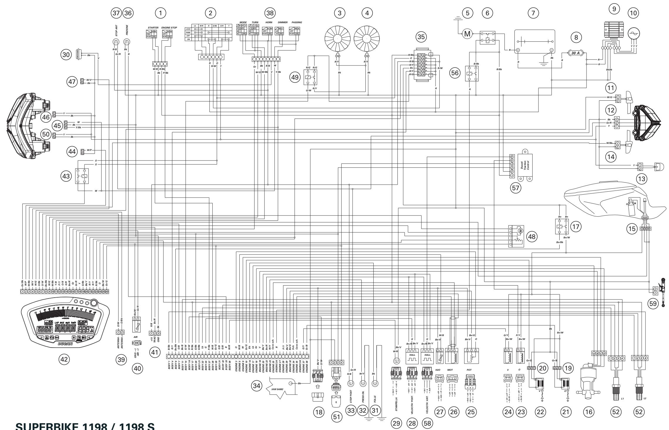
DUCATISUPERBIKE 1198/1198S
DUCATISUPERBIKE
1198 / 1198S

We would like to welcome you among Ducati enthusiasts, and congratulate you on your excellent choice of motorcycle. We are sure that you will use your Ducati for longer journeys as well as short daily trips, but however you use your motorcycle, Ducati Motor Holding S.p.a wishes you an enjoyable ride.
We are continuously working to improve our Technical Assistance service. For this reason, we recommend that you follow strictly the instructions in this manual, especially those regarding the running-in period. This will ensure that your Ducati motorcycle will continue to be a pleasure to ride. For repairs or advice, please contact one of our authorized service centres.
We also provide an information service for all Ducati owners and enthusiasts for any advice and suggestions you might need.
Enjoy the ride!

Notes
Ducati Motor Holding S.p.A. cannot accept any liability for errors that may have occurred in the preparation of this manual. All information in this manual is valid at the time of going to print. Ducati Motor Holding S.p.A. reserves the right to make any modifications required due to the ongoing development of their products.
For safety and reliability, to avoid invalidating the warranty and to maintain the value of your motorcycle, use only original Ducati spare parts.

Warning
This manual is an integral part of the motorcycle and if ownership of the motorcycle is transferred to a third party, the manual must be handed over to the new owner.
Table of contents
General indications 6
Warranty 6
Symbols 6
Useful road safety information 7
Riding with a full load 8
Identification data 9
Controls 10
Position of the motorcycle controls 10
Instrument panel 11
LCD - Main functions 13
LCD-How to set/display parameters 15
The immobilizer system 45
Code card 46
Immobilizer override procedure 47
Duplicate keys 49
Ignition switch and steering lock 50
Left-hand handlebar switch 51
Clutch lever 52
Right-hand handlebar switch 53
Throttle twistgrip 53
Front brake lever 54
Rear brake pedal 55
Gearchange pedal 55
Adjusting the position of the gearchange and rear brake
pedals 56
Main components and devices 58
Position on motorcycle 58
Fuel tank filler cap 59
Seat lock 60
Sidestand 61
Steering damper 62
Front fork adjusters 63
Shock absorber adjusters 65
Adjusting the rear ride height 67
Riding the motorcycle 69
Running-in recommendations 69
Pre-ride checks 71
Starting the engine 72
Moving off 74
Braking 74
Stopping the motorcycle 75
Parking 75
Refuelling 76
Toolkit and accessories 77
Ducati Data Analyzer with USB (for 1198S only) 78
Main maintenance operations 79
Removal of the fairings 79
Checking and topping up the coolant level 83
Checking the brake and clutch fluid level 84
Checking the brake pads for wear 86
Lubricating cables and linkages 87
Adjustment of the throttle cable free play 88
Charging the battery 89
Checking the chain tension 90
Lubricating the drive chain 91
Changing the high and low beam bulbs 92
Changing the sidelight bulb 94
Rear turn signals 95
Number plate light 95
Headlight aim 96
Rearview mirror adjustment 97
Tubeless tyres 98
Checking the engine oil level 100
Cleaning and renewing the spark plugs 101
General cleaning 102
Storing the motorcycle 103
Important notes 103
Maintenance 104
Programmed maintenance plan: operations to be carried out by the dealer 104
Programmed maintenance plan: operations to be carried out by the customer 107
Technical data 108
Overall dimensions (mm) 108
Weights 108
Engine 110
Timing system 110
Performance data 111
Spark plug 111
Fuel system 111
Brakes 112
Transmission 113
Frame 114
Wheels 114
Tyres 114
Suspension 114
Exhaust system 115
Colour schemes 115
Electrical system 115
Routine maintenance record 120
For United States of America version
Only 121
Reporting of safety defects 121
Safety warnings 121
Noise emission warranty 121
Noise and exhaust emission control system information 121
Tampering warning 122
Riding safety 123
Protective apparel 124
Vehicle identification number (VIN); 124
Label location 125
California evaporation emission system 127
Ducati limited warranty on emission control system 127
Routine maintenance record 130
General indications
Warranty
In your own interest, and in order to guarantee product reliability, you are strongly advised to refer to a Ducati Dealer or Authorized Workshop for servicing that requires any particular technical expertise.
Our highly skilled staff have the tools required to perform any servicing job to the highest professional standards, using only Ducati original spare parts to ensure full interchangeability, smooth running and long life.
All Ducati motorcycles come with a Warranty Booklet. However, the warranty does not apply to motorcycles used in competitions. If any motorcycle part is tampered with, modified, or replaced with parts other than original Ducati spare parts during the warranty period, the warranty is automatically invalidated.
Symbols
Ducati Motor Holding S.p.A. advises you to read this manual carefully in order to familiarise yourself with your motorcycle. If in doubt, please contact a Ducati Dealer or Authorized Service Centre. You will find the information in the manual useful on trips (which Ducati Motor Holding S.p.A. hopes will be smooth and enjoyable), and it will help you obtain top performance from your motorcycle for a long time.
This booklet uses a set of symbols with special meanings:
Warning
Failure to comply with these instructions may put you at risk, and could lead to severe injury or even death.
Important
Risk of damage to the motorcycle and/or its components.
Notes
Additional information about the current operation.
References to the right or left side of the motorcycle assume you are sitting on the seat, facing forward.
Useful road safety information

Warning
Read this section before riding your motorcycle.
Many accidents are the result of the inexperience of the rider. Always make sure you have your licence with you; you need a valid licence that entitles you to ride a motorcycle. Do not lend your motorcycle to persons who are inexperienced or do not hold a valid licence.
Riders and passengers must always wear appropriate clothing and a safety helmet.
Do not wear loose clothes or accessories that could become tangled in the controls or limit your field of vision.
Never start or run the engine in enclosed space.
Exhaust gases are toxic and may lead to loss of consciousness or even death within a short time.
The rider should keep his/her feet on the footrests when the motorcycle is in motion.
Always hold the handlebars firmly with both hands so you will be ready for sudden changes in direction or in the road surface. The pillion passenger should always hold on to the strap on the pillion seat with both hands.
Obey the legal requirements and observe national and local regulations.
Always respect speed limits where these apply, and never exceed the speed allowed by the particular visibility, road and traffic conditions.
Always signal your intention to turn or change lane in good time, using the appropriate turn signals.
Be sure you are clearly visible and avoid riding within the blind spot of a vehicle in front of you.
Be very careful at road junctions, or when riding in areas near exits from private land or car parks, or on the slip roads to motorways.
Always turn off the engine when refuelling. Be extremely careful not to spill fuel on the engine or on the exhaust pipe when refuelling.
Do not smoke when refuelling.
While refuelling, it is possible to inhale noxious fuel vapours. Should any fuel drops be spilled on your skin or clothing, immediately wash with soap and water and change your clothing.
Always remove the key if leaving your motorcycle unattended. The engine, exhaust pipes and silencers remain hot for a long time.

Warning
The exhaust system may still be hot even after engine is switched off; so take special care not to touch it with any part of the body and do not park the motorcycle next to inflammable material (wood, leaves, etc.).
Park your motorcycle where no one is likely to knock against it, and use the sidestand.
Never park on uneven or soft ground, or your motorcycle may fall over.
Riding with a full load
Your motorcycle is designed for travelling over long distances with a full load in complete safety.
Even weight distribution is critical for maintaining safety standards, and to avoid getting into difficulties when making sudden manoeuvres or riding on bumpy roads.
Information on load capacity
The total weight of the motorcycle in running order with rider, luggage and additional accessories should not exceed 390 kg.
Arrange your luggage or heavy accessories in the lowest possible position and as close to centre of the motorcycle as possible.
Secure the luggage firmly to the motorcycle structure.
Luggage incorrectly secured may cause the motorcycle to become unstable.
Never attach bulky or heavy objects to the top yoke or front mudguard, as this would cause dangerous instability.
Do not insert objects into gaps in the frame, where they could interfere with moving parts.
Check that the tyres are inflated to the pressure indicated on page 98 and that they are in good condition.
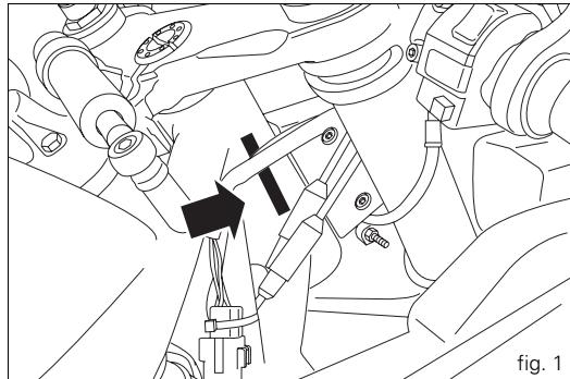
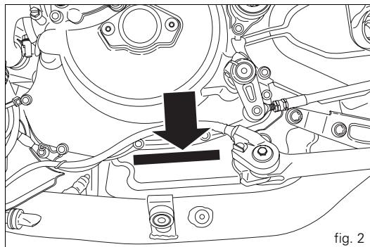
Identification data
All Ducati motorcycles have two identification numbers, one for the frame (fig. 1) and one for the engine (fig. 2).
Frame number
Engine number

Notes
These numbers indicate the motorcycle model and should be quoted when ordering spare parts.
Controls
Warning
This section shows the position and function of the controls used to drive the motorcycle. Be sure to read this information carefully before you use the controls.
Position of the motorcycle controls (fig. 3)
1) Instrument panel.
2) Key-operated ignition switch and steering lock.
3) Left-hand handlebar switch.
4) Clutch lever.
5) Rear brake pedal.
6) Right-hand handlebar switch.
7) Throttle twistgrip.
8) Front brake lever.
9) Gearchange pedal.
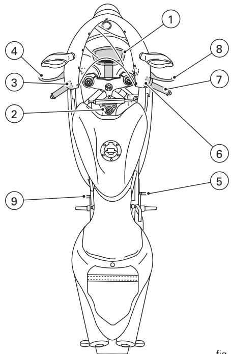
fig. 3
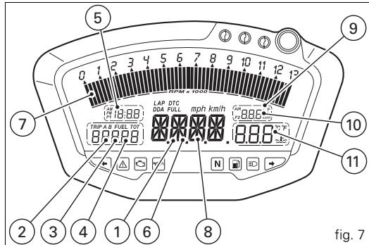
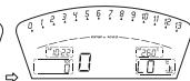
Instrument panel (fig. 4)
1) LCD, (see page 13).
2) Tachometer (rpm).
Indicates engine revs per minute.
3) Neutral (N) indicator (green).
Illuminates when the gearbox is in neutral.
4) Fuel warning light (yellow).
Illuminates when there are approximately 3 litres of fuel left in the tank.
5) Turn signal indicator light (green).
Illuminates and flashes when the turn signal is in operation.
6) Engine oil pressure warning light (red).
Illuminates when engine oil pressure is too low. This light should illuminate when the ignition is switched to ON and should go out a few seconds after the engine starts.
It may come on briefly if the engine is very hot, but should go out again as engine speed increases.

Important
If this light (6) stays on, stop the engine to avoid
serious damage.
7) High beam warning light (blue).
Illuminates when the high beam headlight is on.
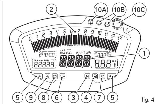
8) "EOBD engine diagnostics light" (amber).
The engine ECU illuminates this light to indicate errors and, in certain cases, consequent engine lockup.
9) "Motorcycle diagnostics" light.
Illuminates when the motorcycle diagnostics detects a problem.
10) OVER REV warning lights.
Indicator light 10A: illuminates steadily at 800rpm before intervention of the rev limiter.
Indicator lights 10A + 10B : illuminate steadily 400~rpm before intervention of the rev limiter.
Indicator lights 10A + 10B + 10C : start flashing when the rev limiter is reached.
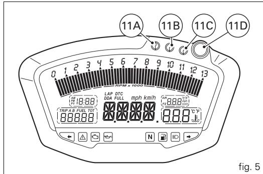
11) Traction Control light (fig. 5).
Indicator light 11A: with DTC activated, illuminates when minimal torque reduction is applied.
Indicator lights 11A + 11B with DTC activated, illuminates when low level torque reduction is applied.
Indicator lights 11A + 11B + 11C with DTC activated, illuminates when medium level torque reduction is applied. Indicator lights 11A + 11B + 11C + 11D with DTC activated, illuminates when high level torque reduction is applied.
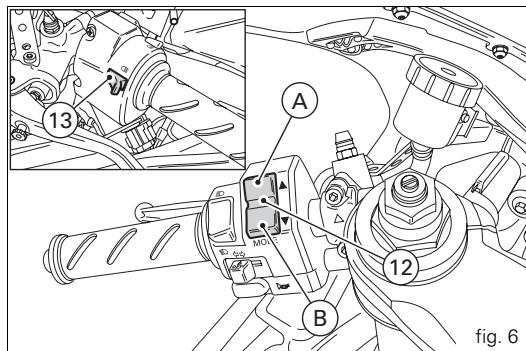
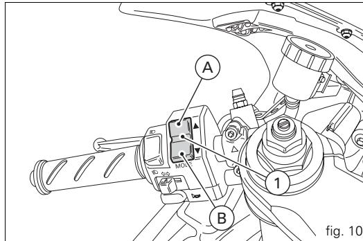
12) 2-position switch A and B (fig. 6).
Switch used for displaying and setting instrument panel parameters. It has two positions, A "▲" and B "▼".
13) High beam headlight flasher switch (fig. 6).
The high beam headlight flasher switch is also used for the LAP and DDA data acquisition functions.
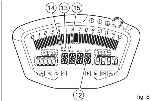
LCD - Main functions

Warning
Any adjustments to the instrument panel must only be
carried out when the motorcycle is stationary. Never operate the instrument panel controls while riding the motorcycle.
1) Speedometer.
Indicates road speed.
2) Odometer.
Shows total distance travelled.
3) Trip meter.
Shows the distance travelled since the last reset (TRIP A and TRIP B).
4) Fuel reserve trip counter.
Shows distance travelled on reserve fuel.
5)Clock.
6) Lap time.
7) Rev counter (RPM).
8) Recording of lap time, maximum speed and maximum rpm (LAP).
9) Battery voltage indicator (BATT).
10) Air temperature indicator.
11) Coolant temperature indicator.
Indicates engine coolant temperature.

Important
Stop riding if the temperature reaches the maximum
value, otherwise the engine might be damaged.
12) Service indicator (SERV).
The message "SERV" indicates that the service interval has been reached. The message is displayed only at Key-On for 5 seconds. The service indicator will be reset at an authorized Ducati Service Centre during servicing.
13) LAP function.
Indicates that the LAP function has been activated.
14) DDA function.
Indicates that the DDA function has been activated.
15) Ducati Traction Control (DTC).
Indicates activation of the DTC control unit.

Important
The instrument panel incorporates diagnostic functions for the electronic injection/ignition system. If you accidentally access a restricted menu, do not under any circumstances attempt to use it, but turn the ignition key to OFF. In the case of any problems, contact an authorized Ducati service centre to carry outthe necessary checks.
LCD - How to set/display parameters
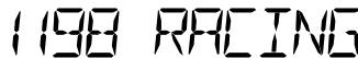
At key-on (key turned from OFF to ON) the instrument panel activates all the digits of the LCD for 1 second and switches on the indicator lights in sequence.
It then reverts to "normal" mode and, in place of motorcycle speed, shows the model and, for 2 seconds, also the version (EU, UK, USA, CND, FRA, JAP).
The model is displayed cyclically until the engine is started.

Notes
For the 1198S version with the Ducati Performance kit
"Complete Exhaust" installed, at key-on the instrument panel will display the message:

Warning
The Ducati Performance kit "Complete Exhaust" is
intended for track use ONLY.
ENGINE OFF
ENGINE OFF
ENGINE OFF
ENGINE OFF
ENGINE OFF
ENGINE RUNNING
fig. 9
At Key-On, the instrument panel always shows the following information (de-activating any previously activated functions, with the exception of the Traction Control function):
Odometer
Air temperature
Clock
Speed
Coolant temperature
Engine rpm
At this point, with switch (1, fig. 10) in position B "▼", it is possible to switch from the Odometer (TOT) display function to the following functions:
TRIP A
TRIP B
TRIP FUEL (only if active)
DTC (only available if Traction Control is both present and activated) before returning to the Odometer (TOT) function.
If, however, you press button (1, fig. 10) in position A "▲", the system enters MENU mode and displays the following functions in sequence:
Error (only if at least one error is present)
BATT
RPM
LAP (OFF or ON)
LAP MEM
DDA (OFF or ON)
Erase DDA
DTC OFF/ON (only active if Traction Control is present)
DTC Setup (active only if DTC is activated) TIME Set
CODE (only if active)

Important
This menu is active only if the speed of the motorcycle is less than 20km / h . If this menu is on the display and the speed of the motorcycle exceeds 20km / h , the instrument panel automatically exits the menu and returns to the initial display. It is possible to exit the menu at any time, however, by pressing switch (1, fig. 10) in position A “▲” for 3 seconds.
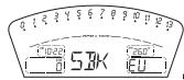
Total distance travelled indicator (odometer)
This function enables display of the total distance travelled. At Key-On the system automatically enters this function. The reading is saved permanently and cannot be reset. If the distance travelled exceeds 99999 km (or 99999 miles), the value "99999" will be displayed permanently.
vs. EU, CND, FRA, JAP
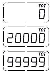
vs. UK, USA
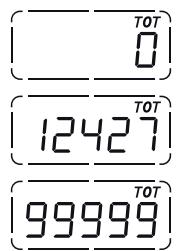
fig. 11
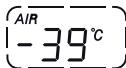
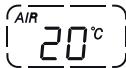
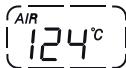
Air temperature indicator
This function displays the external air temperature.
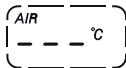
Display limits: -39 °C to +124 °C.
In the event of a sensor FAULT (-40 °C, +125 °C or
disconnected) a series of dashes "---" is displayed steadily and the engine diagnostics warning light (8, fig. 4) comes on.
vs. EU, UK, CND, FRA, JAP
vs. USA
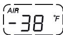
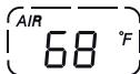
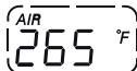
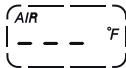
fig. 12
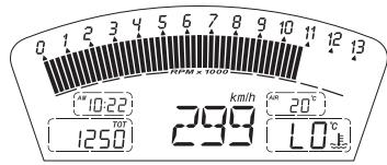
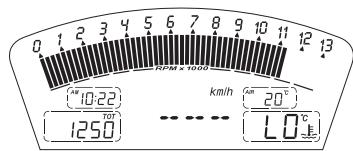
Motorcycle speed
This function displays the motorcycle speed.
The instrument panel receives the actual speed value (expressed in km/h) from the ECU and displays the value increased by 8% .
The maximum speed that can be displayed is 299km / h (186 mph).
Over 299 km/h (186 mph) the display will show a series of dashes "---" (steadily lit - not flashing).
vs. EU, CND, FRA JAP
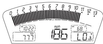
v.s. UK, USA
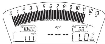
fig. 13
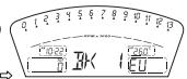
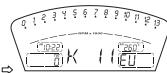
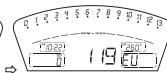
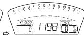
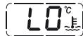
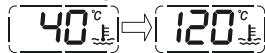
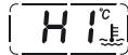
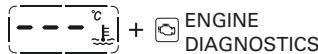
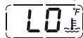
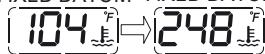
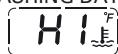
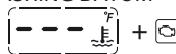
Coolant temperature indicator
Displays the engine coolant temperature:
- if the reading is less than or equal to -40^(-40^) , the display shows a series of flashing dashes ("---") and the Engine Diagnostics warning light (8, fig. 4) comes on;
- if the reading is between -39^ (-38^) and +39^ (+102^) , the message "LO" is displayed steadily;
- if the reading is between +40^ (+104^) and +120^ (+248^) , the message "LO" is displayed steadily;
- if the reading is between +121^ C ( +250^ F ) and +124^ C ( +255^ F ), the message "LO" is displayed steadily;
- if the reading is greater than or equal to +125^ (+257^) , the display shows a series of flashing dashes ("--") and the Engine Diagnostics warning light (9, fig. 4) comes on.
- In the event of a fault, the display will show a series of flashing dashes ("---") and the Engine Diagnostics light (8, fig. 4) will come on.
vs. EU, UK, CND, FRA, JAP
FIXED DATUM
FIXED DATUM FIXED DATUM
FLASHING DATUM
FLASHING DATUM
vs. USA
FIXED DATUM
FIXED DATUM FIXED DATUM
FLASHING DATUM
FLASHING DATUM
ENGINE
DIAGNOSTICS
fig. 14
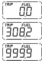
Trip meter "TRIP A"
This function displays the distance travelled since the last reset.
While in this function, if you press switch (1, fig. 10) in
position B "▼" for 3 seconds, the reading is reset.
If the reading exceeds 999.9, it is reset to zero and the
count restarts automatically.
vs. EU, CND, FRA, JAP
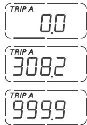
vs. UK, USA
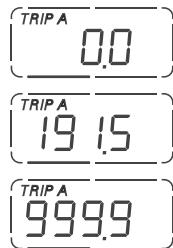
fig. 15
Trip meter "TRIP B"
This function displays the distance travelled since the last reset.
While in this function, if you press switch (1, fig. 10) in position B "▼" for 3 seconds, the reading is reset.
If the reading exceeds 999.9, it is reset to zero and the count restarts automatically.
vs. EU, CND, FRA, JAP
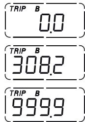
vs. UK, USA
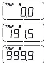
fig. 16
"TRIP FUEL" (distance travelled on reserve fuel) indicator
This function displays the distance travelled on reserve fuel. When the fuel warning light comes on, the TRIP FUEL meter is activated automatically, regardless of the function displayed. If the fuel level remains in reserve, the reading is saved even after Key-Off.
The count stops automatically when the fuel level rises above reserve.
If the reading exceeds 999.9, it is reset and the count restarts automatically.
vs. EU, CND, FRA, JAP
vs. UK, USA
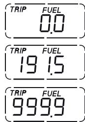
fig.17
Service indicator (SERV)
Indicates that the next service is due.
The message "SERV" appears on the display at the following intervals:
after the first 1000km on the odometer;
every 12000km on the odometer.
The service indicator will remain on the display until reset.
When the service indicator appears, contact your
Ducati dealer or Authorized Service Centre.
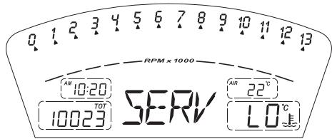
fig. 18
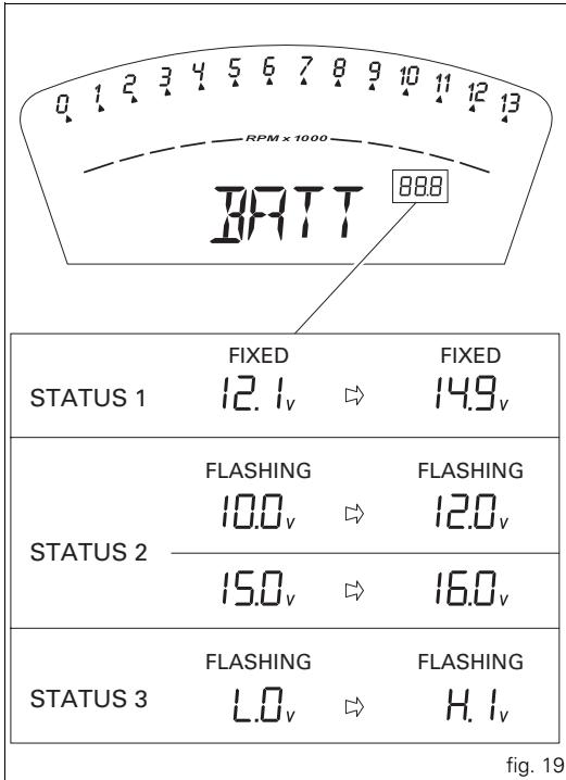
Battery voltage indicator (BATT)
This function displays the battery charge level.
To display this function, go into the menu and select the "BATT" page.
The battery voltage reading is displayed as follows:
- if the reading is between 12.1 and 14.9 Volts, it is steadily illuminated on the display;
- if the reading is between 10.0 and 12.0 Volts or between 15.0 and 16.0 Volts, it flashes on the display;
- if the reading is less than or equal to 9.9 Volts, the message "LO" flashes on the display and the Motorcycle Diagnostics warning light (9, fig. 4) comes on;
- if the reading is greater than or equal to 16.1 Volts, the message "HI" flashes on the display and the Motorcycle Diagnostics warning light (9, fig. 4) comes on.
Engine idle speed adjustment (rpm)
This function displays the engine idle speed adjustment. To display the function, go into the menu and call up the "RPM" page.
In addition to the upper rev counter scale, the display also shows engine rpm numerically so that you can adjust the idle speed more precisely.
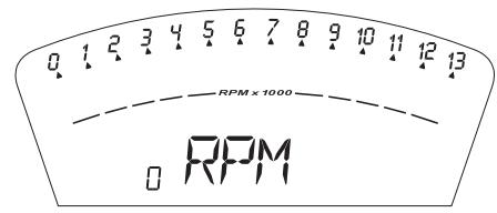
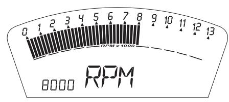
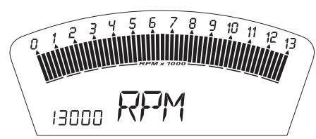
fig. 20
LAP time display function
This function displays the recorded lap time.
To activate this function, go into the menu and set the "LAP" function to "On" by pressing switch (1, fig. 10) in position B "▼" for 3 seconds.
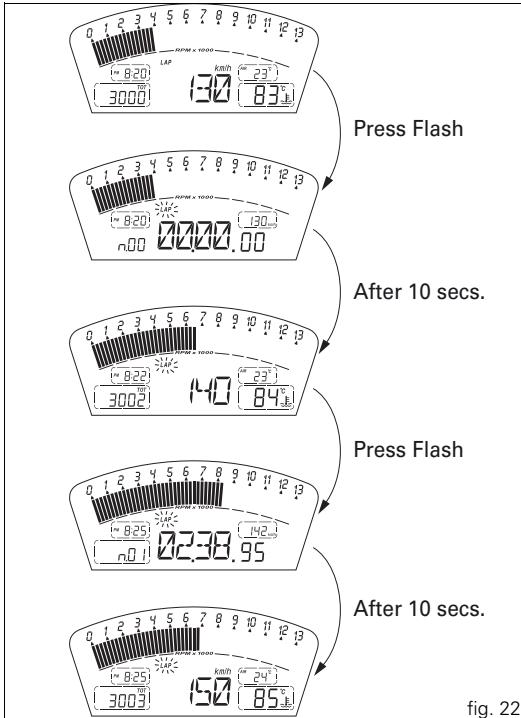
To START and STOP the timer press the high beam flasher switch (12, fig. 5) on the left-hand handlebar switch.
When the LAP function is active, each time you press the flasher switch, the display will show the lap time for 10 seconds, before reverting to normal mode.
You can save a maximum of 30 laps in the memory.
If the memory is full, each time you press the flasher switch, no more lap times can be saved and the display will show the flashing message "FULL" for 3 seconds until the memory is reset.
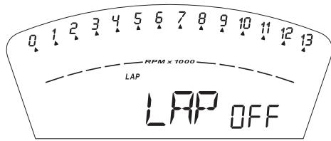
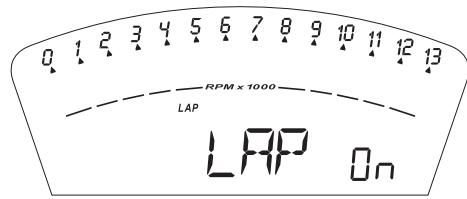
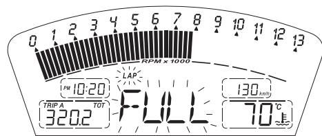
fig. 21
When you switch the LAP function off using the menu, the lap in progress is not saved.
If the LAP function is active and the instrument panel is suddenly switched off (Key-Off), the LAP function is switched off automatically (even if the timer was ON, the lap in progress is not saved).
If the timer is not stopped, when it reaches 99 minutes, 59 seconds and 99 hundredths, it restarts from 0 (zero) and continues until the function is switched off.
If however the LAP function is switched on and the memory has not been cleared, but fewer than 30 laps have been saved (e.g. 18 laps), the instrument panel will save any remaining laps until the memory is full (in this case, it will save a further 12 laps).
In this function, only the lap time is displayed, but other data are also saved (MAX speed, MAX rpm, rev limiter if reached) for viewing at a later date in the Lap Memory function.
LAP Memory display
Displays the data saved using the LAP function: lap time, MAX speed and MAX rpm.
To display the saved lap times, go into the menu and select the "LAP MEM" page.
From this menu page, if you hold pressed switch (1, fig. 10) in position B "▼" for 3 seconds, the data for the first lap will appear. The display will show the lap number, lap time, MAX speed and the MAX rpm reached for the lap in question.
If you press switch (1, fig. 10) in position B "▼", the display scrolls through the 30 lap times saved in the memory, before returning to the 1^st lap.
If you press switch (1, fig. 10) in position B "▼" for 3 seconds while the saved times are displayed, the display immediately resets all the saved times. In this case, if the LAP function was active, it is switched off automatically. The MAX speed saved is the maximum speed indicated on the display in Lap function.
During saving, if the MAX speed shown exceeds 299km / h (186 mph), the speed reached is displayed (e.g. 316 km/h). If there is no reading in the memory, the 30 times are shown, with the display showing "00.00.00", MAX rpm = 0 and MAX speed = 0.
During the lap, if the engine reaches one of the two thresholds before the rev limiter or the rev limiter itself, the respective warning lights (10, fig. 4) come on during the display of the saved times.
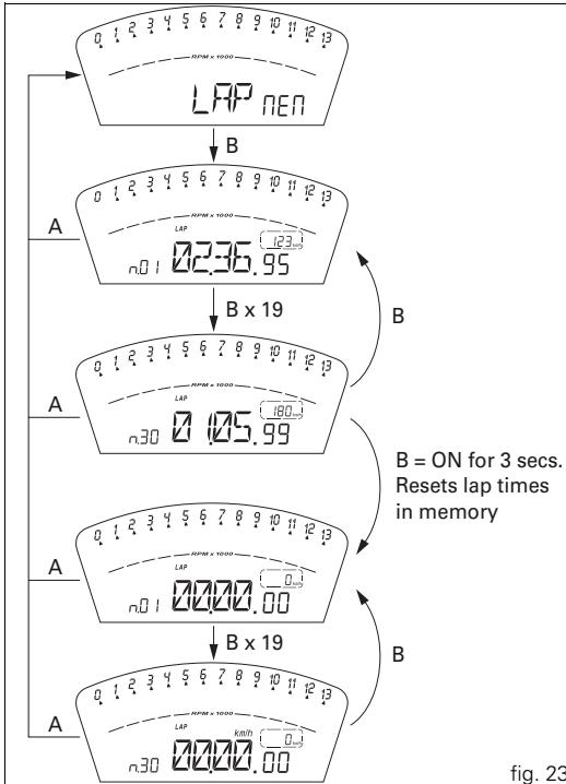
fig. 23
DDA data acquisition
This function serves to activate the DDA (Ducati Data Analyzer) (see page 78): the DDA must be connected to the motorcycle wiring.
To activate the DDA, go into the menu and set the "DDA" to "On" by pressing switch (1, fig. 10) in position B "▼" for 3 seconds.
START and STOP the lap separator by pressing the high beam FLASH button (13, fig. 6) on the left-hand handlebar switch.
If the DDA function is active and the instrument panel is suddenly switched off (Key-Off), the function is automatically disabled.
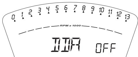
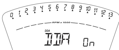
fig. 24
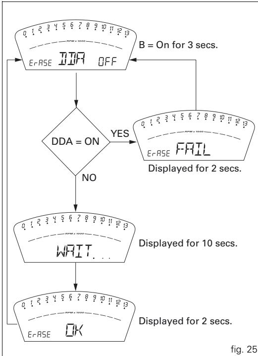
Erase DDA
This function enables you to delete the data saved on the DDA: the DDA must be connected to the motorcycle wiring. To delete the data, enter the menu and select the "Erase DDA" page.
If you press switch (1, fig. 10) in position B "▼" for 3 seconds and the DDA is not acquiring data, the message "WAIT..." appears on the display for 10 seconds. After 10 seconds, the message "ERASE OK" appears for 2 seconds, to confirm that the data has been deleted. If you press switch (1, fig. 10) in position B "▼" for 3 seconds and the DDA is acquiring data, the DAQ memory is not cleared and the display shows the message "FAIL" for 2 seconds.
Function for activation/deactivation of the Ducati Traction Control system

Warning
This function is only available on the 1198S version.
It is used to activate the Ducati Traction Control system: DTC

Warning
Description of the system
DTC is a rider aid that can be used both on the track and the road.
The system is designed to make riding easier and to enhance safety, but in no way relieves the rider of the obligation to drive responsibly. It can also help the rider avoid accidents,
whether caused by his own errors or those of other road users, by improving control and stability during emergency manoeuvres, in accordance with the prescriptions of the highway code.
The rider must always be aware that active safety systems have a preventive function. The active elements help the rider control the motorcycle, making it as easy and safe to ride as possible. The presence of an active safety system should not encourage the rider to ride at speeds beyond the reasonable limits, in accordance with the road conditions, the laws of physics, good riding standards and the requirements of the highway code.
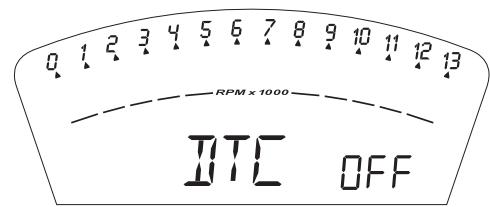
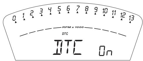
fig. 26
Activation of the system
To activate the system, the motorcycle must be stationary and safely parked.
To enable Traction Control, enter the menu and set "DTC" to "On" by pressing switch (1, fig. 10) in position B "▼" for 3 seconds; once the 3 seconds have elapsed, the message "DTC" will appear on the display to indicate activation of the Ducati Traction Control system. When activated, the message "DTC" is visible both on the normal display and also within the menu pages.

Notes
The functions of the system
To operate the system, the motorcycle must be stationary and safely parked.
Each time DTC is activated, the Traction Control ECU will set the sensitivity level to 8; the level may then be adjusted using the function "Traction Control Sensitivity Level Setting (DTC SETUP)".
To disable Traction Control, enter the menu and set "DTC" to "OFF" by pressing again switch (1, fig. 10) in position B "▼" for 3 seconds; once the 3 seconds have elapsed, the message "DTC" will disappear from the display, thereby indicating deactivation of the Ducati Traction Control system. If the engine is suddenly switched off (Key-Off) while Traction Control is activated, the function will not be disabled but will still be active (DTC On) at the next Key-ON. If, however, battery power is suddenly cut off (Batt-OFF), when battery power is restored and the engine is next switched on (Key-On), the Traction Control will no longer be activated (DTC OFF).
Regular maintenance
To ensure that system continues to function correctly it is necessary to observe the manufacturer's programmed maintenance schedule.
Reasonable errors made by the rider with the DTC system activated.
DTC (Ducati Traction Control) setting function

Warning
This function is only available on the 1198S version.
This function serves to set the intervention level for the ECU of the DTC (Ducati Traction Control).
To set the Traction Control intervention level, with the motorcycle stationary, enter the "Setup DTC" menu page. This page only appears in the menu once the Traction Control ECU has been activated (DTC ON). The Traction Control intervention level setting (L.1.....L.8) is indicated on the right-hand side of the display; the intervention levels range from "1" to "8"; the higher the number, the greater the intervention of the Traction Control system (see following paragraph).
Within this menu page, press switch (1, fig. 10) in position B "▼" for 3 seconds to access the level setting function.
page 1: the display will show "Setup LEV. 1".
If you wish to set this level, press switch (1, fig. 10) in position B "▼" for 3 seconds; the instrument panel will automatically quit this page and return to the initial display, with the level setting indicated on the right-hand side. If instead you wish to set the next highest level, press switch (1, fig. 10) in position B "▼".
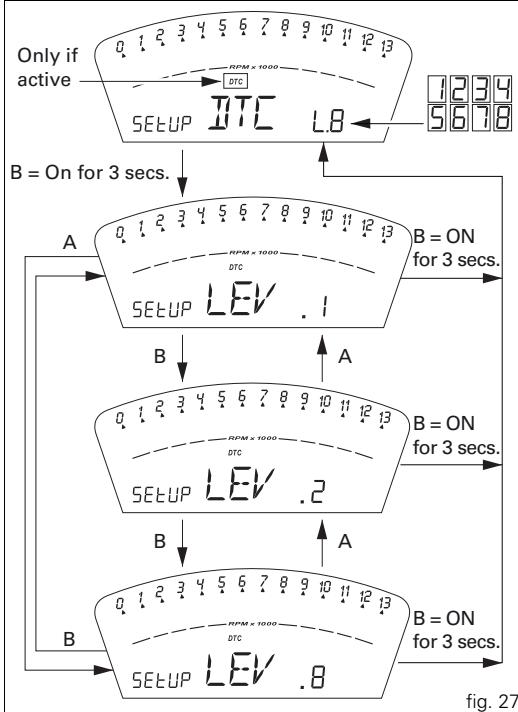
page 2: the display will show "Setup LEV. 2". If you wish to set this level, press switch (1, fig. 10) in position B "▼" for 3 seconds; the instrument panel will automatically quit this page and return to the initial display, with the level setting indicated on the right-hand side. If you wish to set the next highest level, press switch (1, fig. 10) in position B "▼"; to return to the previous level, press switch (1, fig. 10) in position A "▲".
page 3: the display will show "Setup LEV. 3". If you wish to set this level, press switch (1, fig. 10) in position B "▼" for 3 seconds; the instrument panel will automatically quit this page and return to the initial display, with the level setting indicated on the right-hand side. If you wish to set the next highest level, press switch (1, fig. 10) in position B "▼"; to return to the previous level, press switch (1, fig. 10) in position A "▲".
page 4: the display will show "Setup LEV. 4". If you wish to set this level, press switch (1, fig. 10) in position B "▼" for 3 seconds; the instrument panel will automatically quit this page and return to the initial display, with the level setting indicated on the right-hand side. If you wish to set the next highest level, press switch (1, fig. 10) in position B "▼"; to return to the previous level, press switch (1, fig. 10) in position A "▲".
page 5: the display will show "Setup LEV. 5". If you wish to set this level, press switch (1, fig. 10) in position B "▼" for 3 seconds; the instrument panel will automatically quit this page and return to the initial display, with the level setting indicated on the right-hand side. If you wish to set the next highest level, press switch (1, fig. 10) in position B "▼"; to return to the previous level, press switch (1, fig. 10) in position A "▲".
page 6: the display will show "Setup LEV. 6". If you wish to set this level, press switch (1, fig. 10) in position B "▼" for 3 seconds; the instrument panel will automatically quit this page and return to the initial display, with the level setting indicated on the right-hand side. If you wish to set the next highest level, press switch (1, fig. 10) in position B "▼"; to return to the previous level, press switch (1, fig. 10) in position A "▲".
page 7: the display will show "Setup LEV. 7". If you wish to set this level, press switch (1, fig. 10) in position B "▼" for 3 seconds; the instrument panel will automatically quit this page and return to the initial display, with the level setting indicated on the right-hand side. If you wish to set the next highest level, press switch (1, fig. 10) in position B "▼"; to return to the previous level, press switch (1, fig. 10) in position A "▲".
page 8: the display will show "Setup LEV. 8". If you wish to set this level, press switch (1, fig. 10) in position B "▼" for 3 seconds; the instrument panel will automatically quit this page and return to the initial display, with the level setting indicated on the right-hand side. If you wish to set the next highest level, press switch (1, fig. 10) in position B "▼"; to return to the previous level, press switch (1, fig. 10) in position A "▲".
If DTC is activated, the level setting can also be displayed outside the page "SEtUP DTC" at the end of the TOT, TRIP A, TRIP B and TRIP Fuel display functions.
The level setting will remain in memory even after Key-Off.
If however battery power is suddenly cut off (Batt-OFF), when battery power is restored and the engine is next switched on (Key-On), the Traction Control system will no longer be activated (DTC OFF).
Tips on how to select the intervention level
Warning The 8 levels
tyres of the same make, model and size as those originally fitted to the motorcycle.
The use of tyres of different size to the original tyres may alter the operating characteristics of the system.
In the case of minor differences, such as for example, tyres of a different make and/or model than the original, but with the same dimensions (rear = 190/55-17; front = 120/70-17), it may be sufficient simply to select the most suitable level setting from those available to restore optimal system operation.
If tyres of a different size class are used or if the tyre dimensions differ significantly from the original tyres, it may be that the system operation is affected to the point where none of the 8 available level settings will give satisfactory results.
In this case is it is advisable to deactivate the traction control system.
If level 8 is selected, the DTC control unit will intervene at the slightest hint that the rear wheel is starting to spin. Between level 8 and level 1 there are a further 6 intermediate levels. The level of DTC intervention decreases in equal steps from level 8 to level 1.
When levels 1, 2 or 3 is selected the DTC control unit will allow the rear wheel to spin and also slide sideways on exiting a corner; we recommend that this setting is only used by very experienced riders.
The choice of the correct level depends on 3 main variables:
1) The amount of grip available (type of tyre, amount of tyre wear, the track surface, weather conditions, etc.).
2) The characteristics of the circuit (bends all taken at similar speeds or at very different speeds).
3) The riding style (whether the rider favours a more "rounded" or a more "angular" style).
The relation of the DTC intervention level to grip conditions: The choice of level setting depends greatly on the grip conditions of the track/circuit (see below, tips for use on the track and on the road).
The relation of the DTC intervention level to the circuit characteristics:
If all the corners on the track/circuit can be taken at a similar speed, it will be easier to find an intervention level that is satisfactory for every bend; on the other hand, if the track has, for example, one corner that is much slower than all the others, it will necessary to find a compromise level (on the slow corner the DC will tend intervene more than on the faster corners).
The relation of the DTC intervention level to riding style: The DTC will tend to intervene more with a "rounded" riding style, where the bike is leaned over further, rather than with an "angular" style, where the bike is straightened up as quickly possible on exiting a corner.
Tips for use on the track
We recommend that level 8 is used for a couple of full laps (to allow the tyres to warm up) in order to get used to the system. Then try levels 7, 6, etc., in succession until you identify the DTC intervention level that suits you best (always try each level for at least two laps to allow the tyres to warm up).
Once you have found a satisfactory setting for all the corners except one or two slow ones, where the system tends to intervene too much, you can try to modify your riding style slightly to a more "angular" approach to cornering i.e. straighten up more rapidly on exiting the corner, instead of immediately trying a different level setting.
Tips for use on the track
Activate the DTC, select level 8 and ride the motorcycle in your usual style; if the level of DTC intervention seems excessive, try reducing the setting to levels 7, 6, etc., until you find the level that suits you best.
If changes in the grip conditions and/or circuit characteristics and/or your riding style, and the level setting is no longer suitable, switch to the next level up or down and proceed as described above to determine the best setting (e.g. if with level 7 the DTC intervention seems excessive, switch to level 6; alternatively, if on level 7 you cannot perceive any DTC intervention, switch to level 8).
Clock setting function
This function is used to set the clock time.
To set the clock, select the "TIME Set" page from the menu. From this page, if you press switch (1, fig. 10) in position B "▼" for 3 seconds, you enter clock setting mode.
On entering this function, the message "AM" flashes on the display: if you press switch (1, fig. 10) in position B "▼", the message "PM" flashes on the display; pressing switch (1, fig. 8) in position B "▼" again returns you to the previous step (if the time is 00:00, when you switch from AM to PM the time 12:00 will appear);
if you press the switch (1, fig. 10) in position A "▲", you pass to the hours setting mode and the hours digits will start flashingd. Each time you press the switch in position B "▼", the count advances cyclically in steps of 1 hour; if you hold the switch down in position B "▼", the count advances cyclically in steps of 1 hour every second (when the switch is held down continuously, the hours do not flash);
if you press switch (1, fig. 10) in position A "▲", you enter the minutes setting mode and the minute digits will start flashing. Each time you press the switch in position B "▼", the count advances cyclically in steps of 1 minute; if you hold the switch down in position B "▼", the count advances cyclically in steps of 1 minute every second. If the switch is held pressed in position B "▼" for more than 5 seconds, the minutes advance by 1 every 100 ms (when the switch is held in position B "▼" continuously, the seconds do not flash); if you press the switch in position A "▲", the system exits setting mode and displays the newly set time.
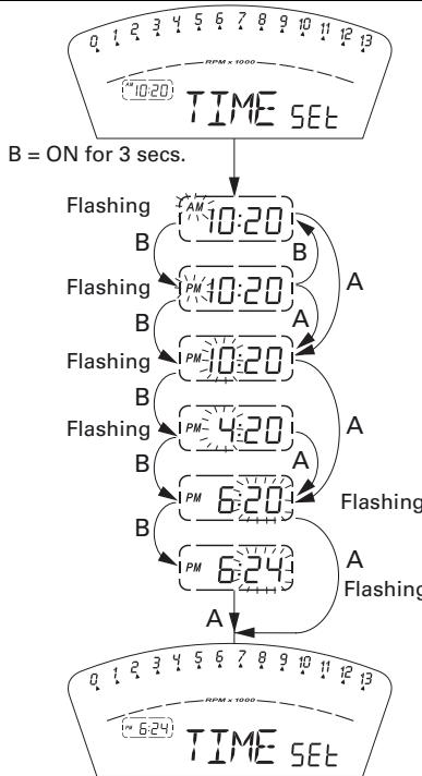
fig. 28
Instrument panel diagnostics

Important
The instrument runs the system diagnostics correctly
60 seconds after the last Key-Off.
Any errors detected in the behaviour of the motorcycle are displayed.
If there are several errors, they are displayed in rolling mode every 3 seconds.
The table below shows the errors that can be displayed.

Warning
Every time an error is displayed, always contact an rized Ducati Service Centre.
| Warning light | Error message | Error | |
| COIL | 8.1 Horizontal cylinder coil error | ||
| COIL | 8.2 Horizontal cylinder coil error | ||
| COIL | 9.1 Vertical cylinder coil error | ||
| COIL | 9.2 Vertical cylinder coil error | ||
| COIL | 10.1 Horizontal cylinder coil error | ||
| COIL | 10.2 Horizontal cylinder coil error | ||
| COIL | 11.1 Vertical cylinder coil error | ||
| Warning light | Error message | Error | |
| COIL | 11.2 Vertical cylinder coil error | ||
| INJE | 12.1 Horizontal cylinder injector error | ||
| INJE | 12.2 Horizontal cylinder injector error | ||
| INJE | 13.1 Vertical cylinder injector error | ||
| INJE | 13.2 Vertical cylinder injector error | ||
| INJE | 14.1 Horizontal cylinder injector error | ||
| INJE | 14.2 Horizontal cylinder injector error | ||
| INJE | 15.1 Vertical cylinder injector error | ||
| INJE | 15.2 Vertical cylinder injector error | ||
| PUMP | 16.0 Fuel pump relay error | ||
| FAN | 18.1 Fan relay error | ||
| Warning light | Error message | Error | |
| FAN | 18.2 | Fan relay error | |
| STRT | 19.1 | Starter contactor error | |
| STRT | 19.2 | Starter contactor error | |
| STEP. | 21.1 | Stepper motor error | |
| STEP. | 21.2 | Stepper motor error | |
| STEP. | 21.3 | Stepper motor error | |
| LAMB. | 22.1 | Lambda heater error | |
| LAMB. | 22.2 | Lambda heater error | |
| EXVL | 23.1 | Exhaust valve motor error | |
| EXVL | 23.2 | Exhaust valve motor error | |
| EXVL | 23.3 | Exhaust valve motor error | |
| EXVL | 23.4 | Exhaust valve motor error | |
| TPS | 1.1 | Throttle position sensor error | |
| TPS | 1.2 | Throttle position sensor error | |
| PRESS | 2.1 | Pressure sensor error | |
| PRESS | 2.2 | Pressure sensor error | |
| T.WAT | 3.1 | Engine coolant temperature sensor error | |
| T.WAT | 3.2 | Engine coolant temperature sensor error | |
| AIR | 4.1 | Air temperature sensor error | |
| AIR | 4.2 | Air temperature sensor error | |
| BATT | 5.1 | Battery voltage error | |
| BATT | 5.2 | Battery voltage error | |
| LAMB | 6.1 | Lambda sensor error | |
| TILT | 6.2 | Lambda 2 sensor error | |
| DTC | 8.0 | Traction control ECU error | |
| ECU | 30.0 | Engine ECU error | |
| PK.up | 34.0 | Pick-up sensor error | |
| SPEE. | 36.0 | Speed sensor error | |
| IMMO | 37.0 | Immobilizer error | |
| IMMO | 37.1 | Immobilizer error | |
| IMMO | 37.3 | Immobilizer error | |
| IMMO | 37.5 | Immobilizer error | |
| CAN | 38.0 | CAN line error | |
Display backlight
The instrument panel backlighting is always activated at keyON. The instrument panel is equipped with internal sensors that detect the ambient light level and at night reduces the maximum backlighting level by 20% to prevent glare.
Intelligent headlight switch-off
This function helps reduce battery use by automatically switching off the headlight. The device is triggered in 3 cases:
- in the first case, if you turn the key from OFF to ON and do not start the engine within 60 seconds, the headlight is turned off and will be turned on again only when the engine is next switched on;
- in the second case, after normal use of the vehicle with the lights on, if the engine is killed via the RUN-STOP button on the RH switch.
In this case, the headlight is switched off 60 seconds after the engine is switched off, and only switched on again the next time the engine is started;
- in the third case, the headlight is switched off while the engine is being started and switched back on again when the engine is running.
Intelligent headlight switch-on
This function allows programmed activation of the headlight even with the motorcycle off (Key-Off).
Immediately after key-off, the instrument panel remains active for 60 seconds, thus allowing the headlight to be switched on if switch (1, fig. 10) is pressed in position A "▲" or B "▼".
During these 60 seconds, each time switch (1, fig. 10) is pressed in position A "▲" or B "▼", the instrument panel will activate the headlight for 30 seconds; each press of switch (1, fig. 10) in position A "▲" or B "▼" will add to the headlight activation time, up to a maximum of 6 presses (equivalent to a maximum activation time of 180 seconds). After the first time you press switch (1, fig. 10) in position A "▲" or B "▼", the period of 30 seconds starts, thus switching on the headlight. Further switch-on time can be added only if you press the switch again within these 30 seconds. If the 30 seconds have elapsed, no further multiples of 30 seconds can be added, and the instrument panel will switch off the headlight.
To reset this function, you must perform at least one Key-On/ Key-Off.
If the battery power is interrupted at any time while this function is active, when power is restored, the instrument panel will de-activate the function (the instrument panel does not remain active for 60 seconds).
The immobilizer system
For additional anti-theft protection, the motorcycle is equipped with an IMMOBILIZER, an electronic system that locks the engine automatically whenever the ignition switch is turned off.
The grip of each ignition key contains an electronic device that modulates the output signal from a special antenna in the switch when the ignition is switched On. The modulated signal represents the "password" (which is changed at each start-up) by which the ECU recognizes the ignition key. The ECU will only allow the engine to start if it recognises this password.
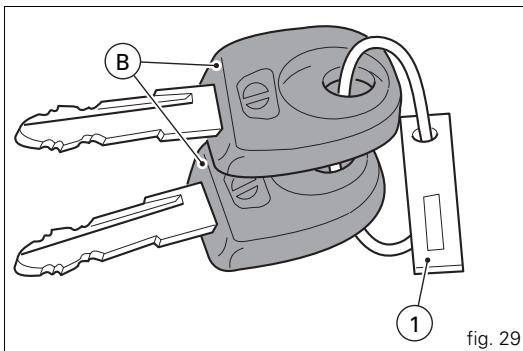
Keys (fig. 29)
The owner receives a set of keys, comprising:
- 2 black keys (B).
These contain the "code" of the immobilizer system.

Notes
Your Ducati dealer may ask you to produce your Code
Card in order to carry out certain servicing operations.
The black keys (B) are the keys for normal use, and are used to:
- start the engine;
- open the lock on the fuel tank filler cap;
- open the seat lock.

Notes
The two keys have a small tag (1) attached, which
shows their identification number.

Warning
Keep the keys separate, and store the tags (1) in a safe
place.
It is also advisable to use only one of the black keys to start the motorcycle.
Code card
A CODE CARD (fig. 30) is supplied with the keys. This shows the electronic code (A, fig. 31) that must be used if the engine is locked by the immobilizer and consequently does not start when the key is turned to ON.

Warning
Keep the CODE CARD in a safe place. We advise the user to keep the code printed on the CODE CARD on his/her person at all times in order to be able to override the engine lock using the procedure described below, in the event of a malfunction of the immobilizer system, signalled by illumination of the amber diagnostic light (9, fig. 4). This operation is only possible if the electronic code indicated on the code card is known.

Warning
1 Your dealer will ask you to produce the Code Card in order to re-program or replace a key.
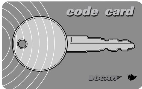
fig. 30
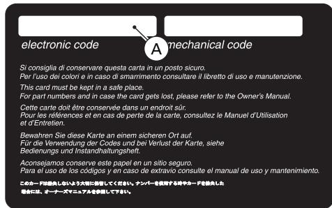
fig. 31
Immobilizer override procedure
Should the immobilizer become locked, you can perform the "Immobilizer Override" procedure from the instrument panel by entering the respective function as follows: Select the "CODE" page from the menu.

Notes
This menu should be active only if there is at least one immobilizer error.
With this page selected, the initial code is always displayed as "00000". If you hold pressed switch (1, fig. 10) in position B "▼" for 3 seconds, you will access the procedure for entering the electronic code given on the Code Card.
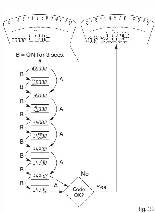
Entering the code:
on entering this function, the first digit on the left starts flashing.
Switch (1, fig. 10):
each time you press the switch in position B "▼", the number increases cyclically in steps of one digit every second; if you press the switch in position A "▲", you can set the second digit, which will start flashing. Each time you press the switch in position B "▼", the number increases cyclically in steps of one digit every second;
if you press the switch in position A "▲", you can set the third digit, which will start flashing. Each time you press the switch in position B "▼", the number increases cyclically in steps of one digit every second;
if you press the switch in position A "▲", you can set the fourth digit, which will start flashing. Each time you press the switch in position B "▼", the number increases cyclically in steps of one digit every second;
if you press the switch in position A "▲", you can set the fifth digit, which will start flashing. Each time you press the switch in position B "▼", the number increases cyclically in steps of one digit every second;
press in position A "▲" to confirm the code.
If the code has been entered correctly, the message CODE and the code itself will flash simultaneously for 4 seconds. The motorcycle diagnostics warning light (9, fig. 4) will go off. The instrument panel then automatically exits the menu, thus allowing "temporary" starting of the motorcycle. If the error persists, at the next key-on, the instrument panel will return to an error state and immobilize the engine. If the code has been entered incorrectly, however, the instrument panel will automatically return to the "CODE" menu and display the code "00000".
Operation
When the ignition key is turned from ON to OFF, the immobilizer system activates the engine lock. When the ignition key is turned from OFF to ON to start the engine: 1) if the code is recognised, the protection system releases the engine lock. When you press the START (2, fig. 37) switch, the engine will start up.
2) if the motorcycle diagnostics warning light (9, fig. 4) comes on and if, when you press switch (1, fig. 10) in the position B "▼", the "Error IMMO" message appears on the display, indicating that the code has not been recognised. In this case, turn the ignition key back to OFF and then to ON again. If the engine still does not start, try again with the other black key. If the engine still does not start, contact the DUCATI Service network.
Warning
Sharp knocks can damage the electronic components inside the key.
Always use the same key throughout the procedure. Using different keys could prevent the system from recognising the code in the key.
Duplicate keys
If you need additional keys, contact your DUCATI Service Centre with all the keys you have in your possession and your CODE CARD.
The Ducati Service Centre will program all the new keys as well as any keys you already have.
You may be asked to provide proof that you are the legitimate owner of the motorcycle.
The codes for any keys not present during the memory programming procedure are cancelled, to ensure that any keys that may have been lost can no longer be used to start the engine.

Notes
If you sell your motorcycle, do not forget to pass on all the keys and the CODE CARD to the new owner.
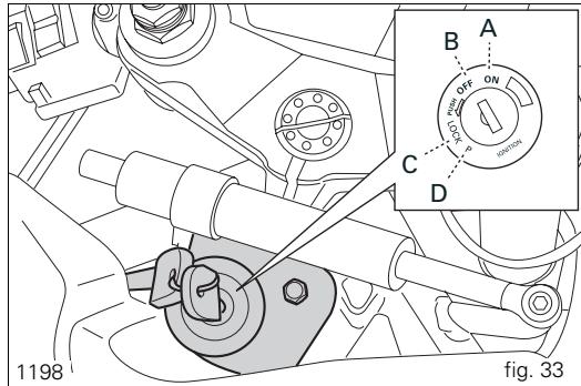
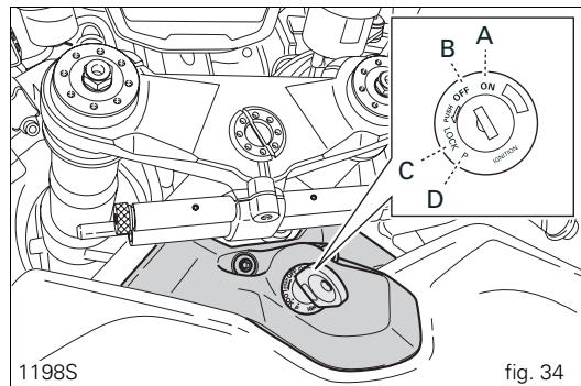
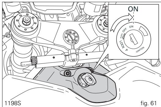
Ignition switch and steering lock
(fig. 33 and fig. 34)
This is located in front of the fuel tank and has four positions:
A) ON: enables lights and engine operation;
B) OFF: disables lights and engine operation;
C) LOCK: the steering is locked;
D) P: parking light on and steering locked.

Notes
To move the key to the latter two positions, push it in before turning. The key can be removed in positions (B), (C) and (D).
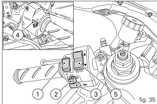
Left-hand handlebar switch (fig. 35)
1) Dip switch, two-position light selector switch: position = low beam headlight on; position = high beam headlight on.
2) Switch = three-position turn signal:
centre position = off;
position left turn;
position right turn.
To cancel the indicator, press the lever once it has returned to the central position.
3)Button 一 = horn.
4) Switch = high beam flasher and instrument panel control.
5) Two-position instrument panel control switch:
position"▲";
position "▼".
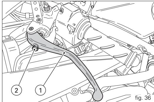
Clutch lever
The lever (1) disengages the clutch. The span adjuster (2) serves to alter the distance of the lever from the handlebar. The lever distance can be adjusted through 10 clicks of the knob (2). Turn the knob clockwise to move the lever away from twistgrip, or anti-clockwise to move it closer. When the clutch lever (1) is operated, drive from the engine to the gearbox and the rear wheel is disengaged. Correct use of the clutch lever is very important in all riding situations, especially when moving off.

Warning
Any adjustment of clutch lever must be carried out motorcycle is stationary.

Important
Using the clutch properly will prolong the life of the engine and prevent any damage to components in the transmission.

Notes
The engine can be started with the sidestand down and the gearbox in neutral. When starting the engine with a gear engaged, pull in the clutch lever (in this case the sidestand must be in the raised position).
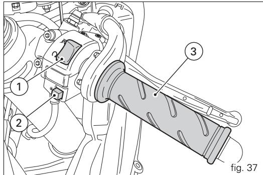
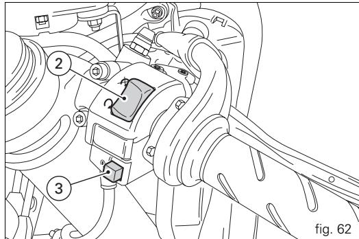
Right-hand handlebar switch (fig. 37)
1) Two-position ENGINE STOP switch:
position (RUN) = run;
position (OFF) = stop engine.

Warning
This switch is mainly intended for use in
emergencies when you need to stop the engine quickly.
After stopping the engine, return the switch to the O position to start the engine.

Important
After travelling with the lights on, if the engine is
switched off using switch (1) and the ignition key is left in the ON position, the battery can be drained since the headlamp remains on.
2) Button () = engine start
Throttle twistgrip (fig. 37)
The twistgrip (3) on the right handlebar opens the butterfly valves in the throttle body. When released, the twistgrip returns automatically to the initial position (idling speed).
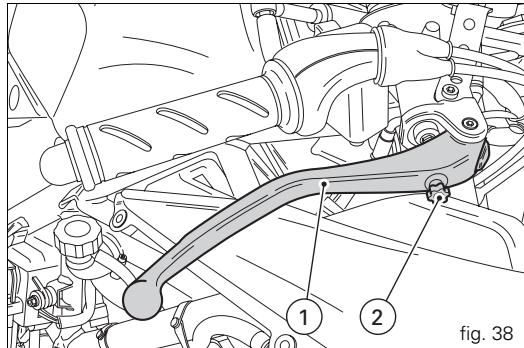
Front brake lever (fig. 38)
Pull the lever (1) towards the twistgrip to operate the front brake. The system is hydraulically assisted and you only need to pull the lever gently.
The brake lever (1) has a knob (2) for adjusting the distance between lever and twistgrip on the handlebar.
The lever distance can be adjusted through 10 clicks of the knob (2). Turn the knob clockwise to move the lever away from twistgrip, or anti-clockwise to move it closer.
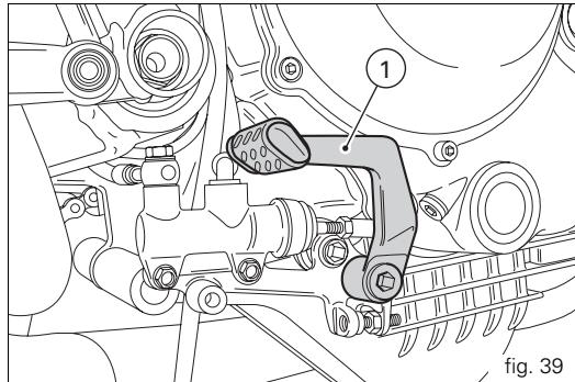
Rear brake pedal (fig. 39)
Push down on the pedal (1) with your foot to operate the rear brake.
The system is controlled hydraulically.
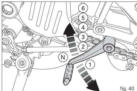
Gearchange pedal (fig. 40)
The gear change pedal is at rest when in centre position N, and automatically returns to the centre position. When in this position, light N (3, fig. 4) on instrument panel comes on.
The pedal can be moved:
downwards = push down on the pedal to engage 1^st gear and to shift down. At this point the N light on the instrument panel will go off;
upwards= lift the pedal to engage 2^nd gear and then 3^rd , 4^th , 5^th and 6^th gears.
Each time you move the pedal you engage the next gear, one gear at a time.
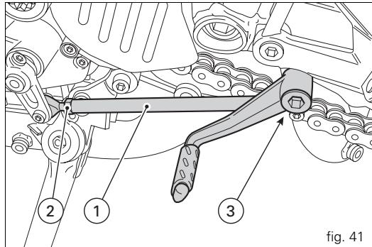
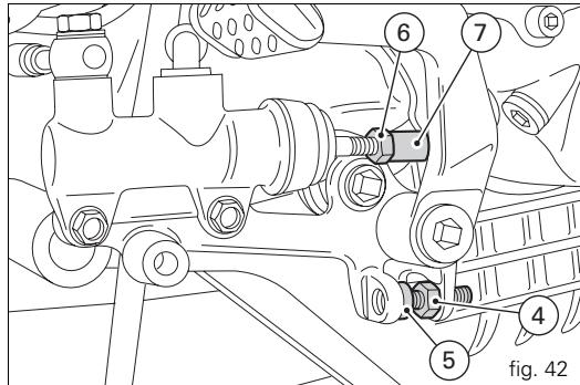
Adjusting the position of the gearchange and rear brake pedals (fig. 41 and fig. 42)
The position of the gearchange and rear brake pedals in relation to the footrests can be adjusted to suit the requirements of the rider.
To adjust the position, proceed as follows: restrain the tie-rod (1) and slacken the locknuts (2) and (3).

Notes
The locknut (2) has a left-hand thread.
Turn the tie-rod (1) using an open-ended wrench on the flats to move the gearchange pedal to the required position.
Tighten both locknuts onto the rod.
To adjust the position of the rear brake pedal, proceed as follows:
Loosen the locknut (4).
Turn the pedal travel adjustment bolt (5) until the pedal is in the desired position.
Tighten the locknut (4) to a torque of 2.3Nm .
Operate the pedal by hand to check that there is 1.5 to 2 mm of freeplay before the brake bites.
If not, adjust the length of the master cylinder pushrod as follows.
Slacken off the locknut (6) on the pushrod.
Screw the rod into the clevis (7) to increase play, or unscrew it to reduce play.
Tighten the lock nut (6) to a torque of 7.5 Nm and re-check the free play.
Main components and devices
Position on motorcycle (fig. 43)
1) Fuel tank filler cap.
2) Seat lock.
3) Sidestand.
4) Steering damper.
5) Rearview mirrors.
6) Front fork adjusters.
7) Rear shock absorber adjusters.
8) Suspension tie-rod for adjustment of rear ride height.
9) Exhaust silencer (see note on page 75).
10) Catalytic converter.
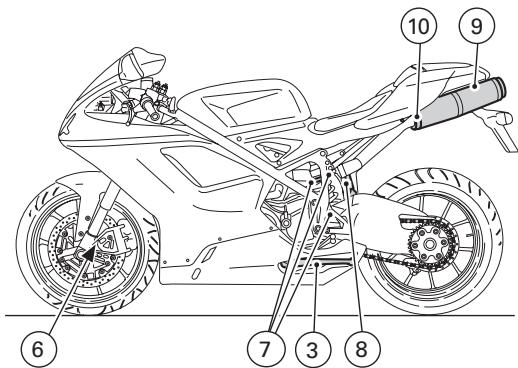
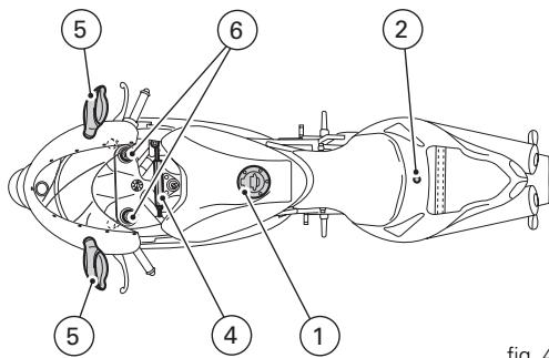
fig. 43
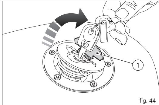
Fuel tank filler cap (fig. 44)
Opening
Raise the cover (1) and insert the key into the lock. Give the key a 1/4 turn clockwise to unlock. Lift the cap.
Closing
Close the cap with the key inserted and push it into its seat. Turn the key anticlockwise to the initial position and remove it. Replace the lock cover (1).

Notes
The cap can only be closed with the key inserted.

Warning
Always make sure you have properly closed the fuel filler cap after refuelling (see page 76).
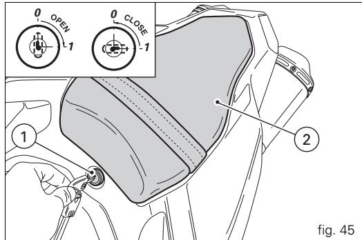
Seat lock
Opening (fig. 45)
Insert the key into the seat lock (1) and turn it clockwise until the seat catch disengages with an audible click. Raise the rear of the seat (2) until it can be extracted.
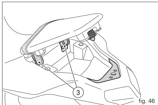
Closing (fig. 46)
Insert the hooks (3) on the base of the seat under the rear subframe.
Press down on the pillion seat until you hear the catch engage with an audible click.
Make sure that the pillion seat is properly secured by gently pulling it upwards.
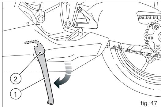
Sidestand (fig. 47)

Important
Before lowering the sidestand, check that the ground
is sufficiently even and firm.
Do not park on soft or pebbled ground or on asphalt melted by the sun, etc. or the motorcycle may fall over.
When parking on a slope, always park with the rear wheel on the downhill side.
To lower the sidestand, hold the motorcycle handlebars with both hands and, with your foot, push down the stand (1) until fully extended. Tilt the motorcycle until the sidestand is resting on the ground.

Warning
Do not sit on the motorcycle when it is supported on
the sidestand.
To raise the sidestand to rest position (horizontal), tilt the motorcycle to the right and, at the same time, lift the stand (1) with your foot.

Notes
It is advisable to check periodically that the stand
mechanism (consisting of two springs, one inside the other)
and safety sensor (2) are working properly.

Notes
The engine can be started with the sidestand down the gearbox in neutral. If starting with a gear engaged, the clutch lever (in this case the sidestand must be used
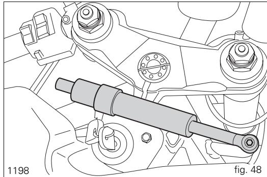
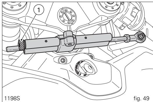
Steering damper (fig. 48 and fig. 49)
The steering damper is located in front of the tank and secured to the frame and the top yoke.
The damper helps improve steering precision and stability, and thus also improves ride quality in all riding conditions.
1198S
Turn the knob (1) clockwise to obtain a stiffer damping action or anticlockwise to soften it.
Each adjustment position is identified by a click.

Warning (1198S)
Never attempt to adjust the knob (1) while riding,
or you may lose control of the motorcycle.
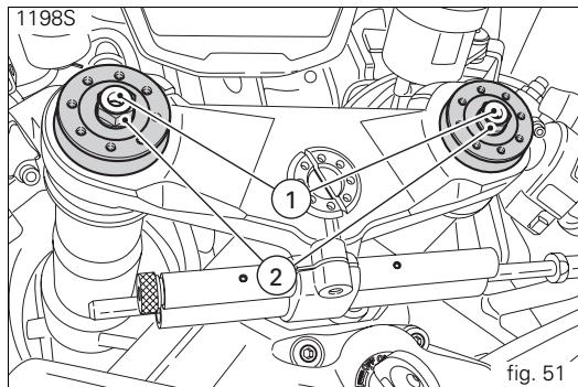
Front fork adjusters
The front fork can be adjusted for rebound, compression and spring preload.
The settings are adjusted by way of external adjuster screws:
1) to adjust rebound damping (fig. 50 and fig. 51);
2) to adjust inner spring preload (fig. 50 and fig. 51);
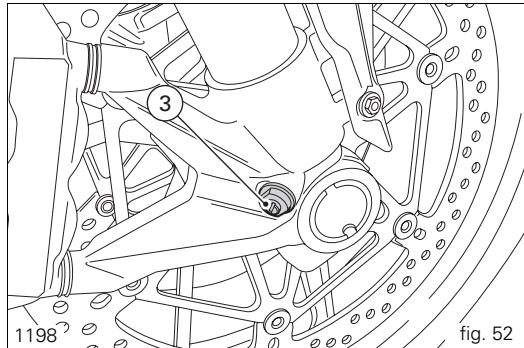
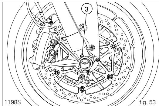
3) to adjust compression damping (fig. 52 and fig. 53).
Park the motorcycle in a stable position on its sidestand. To adjust the rebound damping setting, turn the adjuster (1) on the top of each fork leg with a flat-blade screwdriver (1198) or the special wrench (1198S).
As you turn the adjusting screws (1 and 3), you will hear them click. Each click identifies a setting. The stiffest damping setting is obtained with the adjuster turned fully clockwise to the "0" position. Start with this position and turn counterclockwise. Count the clicks, which correspond to position 1, 2 and so forth.
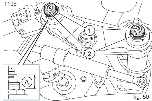
The STANDARD factory settings are as follows:
compression:
3/4 turns (1198),
8 clicks (1198S);
rebound:
12 clicks (1198),
10 clicks (1198S).
Spring preload (1198) (A, fig. 50): 18mm ;
corresponds to an actual preload of 9mm
Spring preload (1198S): starting with the adjuster screwed
FULLY OUT, screw it in clockwise 8 turns;
corresponds to an actual preload of 8 mm.
To change the preload on the inner spring for each fork leg, turn the adjuster with the hex end (2, fig. 50 and fig. 51) with a 22mm hex wrench.

Important
Adjust both fork legs to the same setting.
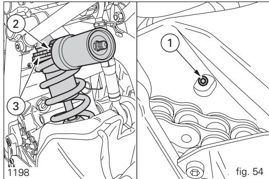
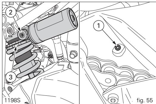
Shock absorber adjusters (fig. 54 and fig. 55)
The shock absorber has external adjusters that enable you to adjust the suspension to suit the load on the motorcycle. Adjuster (1), located on the left-hand side at the point at which the shock absorber is fixed to the swingarm, controls rebound damping.
The adjuster (2) on the shock absorber reservoir controls compression damping.
Turn the adjusters (1 and 2) clockwise to stiffen the damping or anti-clockwise to soften it.
(1198)
STANDARD setting:
from the fully closed position (turned fully clockwise), unscrew: adjuster (1) by 2 turns;
adjuster (2) by 2 turns.
Spring preload: 28mm
(1198S)
STANDARD setting:
from the fully closed position (turned fully clockwise), unscrew:
adjuster (1) by 10 clicks;
adjuster (2) by 10 clicks.
Spring preload: 23mm
The two nuts (3) on the upper part of the shock absorber serve to adjust the preload on the external spring. To change spring preload, slacken off the upper lock nut.
Then tighten or loosen the lower nut to increase or decrease spring preload as required.
Once the desired spring preload has been set, re-tighten the upper lock nut.
Warning
Use a pin wrench to turn the preload adjusting nut. Take special care when turning the nut, to avoid injuring your hand by striking it violently against other parts of the motorcycle if the wrench suddenly slips off the nut while turning.
Warning
The shock absorber is filled with gas under pressure and may cause severe damage if taken apart by unskilled persons.
If you plan to carry a passenger and luggage, adjust the rear shock absorber spring load to the maximum setting to improve the handling characteristics of the motorcycle and to avoid the possibility of ground contact. It may also be necessary to adjust the rebound damping accordingly.
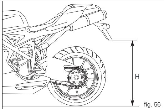
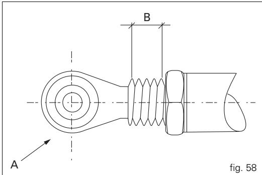
Adjusting the rear ride height
(fig. 56, fig. 57 and fig. 58)
The standard ride height setting is the result of rigorous testing carried out in a wide variety of conditions by our technical staff.
Modifying the the ride height is a very critical operation, and can be dangerous if carried out by untrained persons. Before changing the standard setting, measure the reference value (H, fig. 56).
The rider can adjust the rear ride height to suit his/her needs by changing the working position of the rear shock absorber. To alter the eye to eye length of the tie-rod (1), slacken the locknuts (3).

Notes
Note that the lower nut (3) has a left-hand thread.
Use an open-end wrench on the flats (4) of the tie-rod (2). Once the tie-rod length is adjusted correctly, tighten the nuts (3) to 25Nm

Warning
The length of the tie-rod (2) between the centres of bo eyes (1) should not exceed 285 mm.
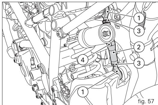
The maximum distance that the UNIBALL end fitting (A) can be unscrewed from the tie-rod body is 5 threads, or 7.5mm B
Riding the motorcycle
To allow all the mechanical moving parts in the motorcycle to adapt to one another, and to avoid shortening the life of the main engine components, it is advisable to avoid sudden acceleration and running the engine at high rpm for too long, especially uphill.
It is also advisable to check the drive chain frequently and ensure that it is lubricated as required.
Running-in recommendations
Max. rpm (fig. 59)
Rpm limits to be observed during the running-in period and in normal use:
1) up to 1000km ;
2) from 1000 to 2500km
Up to 1000 km
During the first 1000km ,keep an eye on the tachometer.
The revs should never exceed:
5.500÷6000 rpm.
During the first hours of riding, it is advisable to continuously vary the load on the engine and the rpm, though still keeping within the above limits.
For this reason, roads with numerous bends and hilly areas are ideal for running in the engine, brakes and suspension.
For the first 100 km use the brakes gently. Avoid sudden or prolonged braking. This will allow the friction material on the brake pads to bed in against the brake discs.
From 1000 to 2500 km
At this point, you can ask for more power from the engine, being careful, however, never to exceed: 7000 rpm.

Important
Throughout the running-in period, be careful to stick to the recommended maintenance schedule and periodic service intervals indicated in the warranty booklet. Failure to follow these instructions releases Ducati Motor Holding S.p.A. from any liability whatsoever for any engine damage or shorter engine life.
Keeping to the running-in recommendations will ensure longer engine life and reduce the need for overhauls and re-tuning.
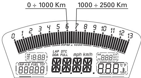
fig. 59
Pre-ride checks

Warning
Failure to carry out these checks before starting may
result in damage to the motorcycle and injury to rider.
Before starting, check the following points:
Fuel level in the tank
Check the fuel level in the tank. Re-fuel if necessary (page 76).
Engine oil level
Check the oil level in the sump through the sight glass.
Top up if necessary (page 100).
Brake and clutch fluid
Check the fluid levels in the respective reservoirs (page 84).
Coolant
Check the coolant level in the expansion tank and top up if necessary (page 83).
Tyre condition
Check the pressure and condition of the tyres (page 98).
Controls
Operate the brake, clutch, throttle and gear change controls (levers, pedals and twistgrip) to check that they function correctly.
Lights and indicators
Make sure the lights, indicators and horn work properly. Replace any burnt-out bulbs (page 92).
Key locks
Check that the fuel filler cap (page 59) and the seat lock (page 60) are closed firmly.
Sidestand
Make sure sidestand operates smoothly and is in the correct position (page 61).

Warning
If there are any faults or malfunctions, do not start orcycle and contact your DUCATI Dealer or
Authorized Service Centre.
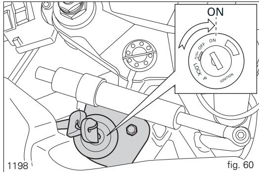
Starting the engine

Warning
Before starting the engine, familiarise yourself with
the controls that you will use when riding (page 10).

Warning
Never start or run the engine in enclosed space.
Exhaust gases are toxic and may lead to loss of consciousness or even death within a short time.
1) Turn the ignition key to ON (fig. 60 and fig. 61).
Check that both the green light N and the red light on the instrument panel come on.

Important
The oil pressure warning light should go out a few seconds after the engine has started (page 11).

Warning
The sidestand should be in rest position (horizontal), otherwise the safety sensor prevents the engine starting.

Notes
The engine can be started with the sidestand down and the gearbox in neutral. If starting with a gear engaged, pull in the clutch lever (in this case the sidestand must be up).
2) Check that the stop switch (2, fig. 62) is positioned to O (RUN), then press the starter button (3, fig. 62).

Important
Do not rev the engine when cold. Allow some time for the oil to warm up and reach all points that need lubricating.
Moving off
1) Disengage the clutch by squeezing the clutch lever.
2) Push down the gearchange lever firmly with the tip of your foot to engage first gear.
3) Raise the engine revs by turning the throttle twistgrip while gradually releasing the clutch lever. The motorcycle will start moving.
4) Release the clutch lever completely and accelerate.
5) To change up to the next gear, close the throttle to reduce the engine revs, disengage the clutch, lift the gearchange lever and release the clutch lever.
To change down, proceed as follows: release the twistgrip, disengage the clutch, briefly rev the engine to allow the gears to synchronize, shift down and release the clutch lever. Use the controls intelligently and opportunely: when riding uphill, do not hesitate to shift down as soon as the motorcycle starts to slow down, so you will avoid overloading the engine and putting too much strain on the the motorcycle generally.

Important
Avoid sudden acceleration, as this may lead to
misfiring and transmission snatching. The clutch lever should not be held in longer than necessary after a gear is engaged, otherwise friction parts may overheat and wear out.
Braking
Slow down in time, change down to use the engine brake, then apply both brakes. Pull in the clutch lever before the motorcycle comes to a stop to prevent the engine stalling.

Warning
Use both the brake lever and the brake pedal for effective braking. Using only one of the brakes will give you less braking power.
Never use the brake controls harshly or suddenly as you may lock the wheels and lose control of the motorcycle. When riding in the rain or on slippery surfaces, braking capacity is significantly reduced. Always use the brakes very gently and carefully when riding under these conditions.
Any sudden manoeuvres may lead to loss of control.
When riding down long, steep downhill slopes, change down to use engine braking. Apply the brakes intermittently for brief periods only. Keeping the brakes applied continuously causes the friction material to overheat and dangerously reduces braking effectiveness. Under-inflated or over-inflated tyres reduce braking efficiency and may adversely affect safe riding and road-holding on bends.
Stopping the motorcycle
Reduce speed, change down and release the throttle twistgrip. Change down to engage first gear and then neutral. Apply the brakes and bring the motorcycle to a complete stop. Switch the engine off by turning the key to OFF (page 50).
Parking
Stop and park the motorcycle on the sidestand (see page 61). To prevent theft, turn the handlebar fully left and turn the ignition key to the LOCK position.
If you park in a garage or other indoor area, make sure that there is proper ventilation and that the motorcycle is not near a source of heat.
If necessary, you can leave the sidelights on by turning the key to position P.

Important
Do not leave the key at P for long periods or the
battery will run down. Never leave the motorcycle unattended with the ignition key inserted.

Warning
The exhaust system may still be hot even after
engine is switched off; so take special care not to touch it with any part of the body and do not park the motorcycle next to inflammable material (wood, leaves, etc.).

Warning
Using padlocks or other locks designed to prevent movement of the motorcycle (such as brake disc locks, rear sprocket locks, and so on) is very dangerous, and may impair motorcycle operation and the safety of rider and passenger.
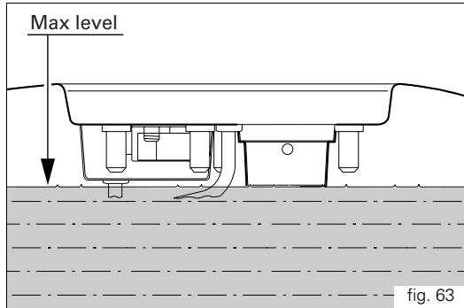
Refuelling (fig. 63)
Do not overfill the tank when refuelling. The fuel level should always be below the rim of the filler recess.

Warning
Use fuel with low lead content and an original octane
number of 95 minimum (see table "Top-ups" on page 109).
Check that no fuel is trapped in the filler cap recess.
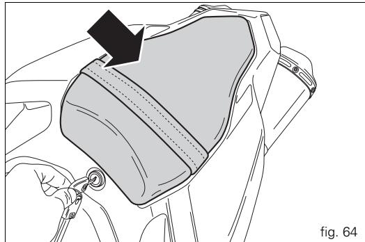
Toolkit and accessories (fig. 64)
The compartment under the pillion seat contains: use and maintenance manual; toolkit consisting of:
- spark plug wrench;
tommy bar for spark plug wrench; - double-ended screwdriver;
- Allen key for fairing panels.
Ducati Data Analyzer with USB (for 1198S only)
A USB DDA (1) is supplied in kit form. To use the DDA, position it under the seat with the cap (2) fitted and the connector (3) from the main wiring loom connected. Refer to the procedure "DDA data acquisition" in the paragraph "LCD - How to set/display parameters".
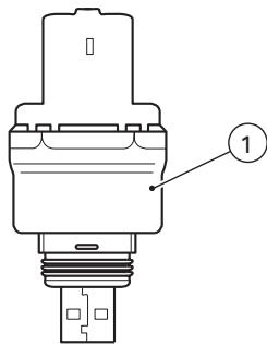
fig. 65
Main maintenance operations
Removal of the fairings
Some parts of the motorcycle fairing have to be removed for certain maintenance or repair operations.

Warning
If parts that have been removed are not refitted
correctly, they may become loose suddenly while riding and cause you to lose control of your motorcycle.

Important
On refitting the headlight fairing, always refit the nylon
washers in correspondence with the retaining screws to avoid damaging the painted parts and the Plexiglas windshield.
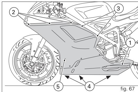
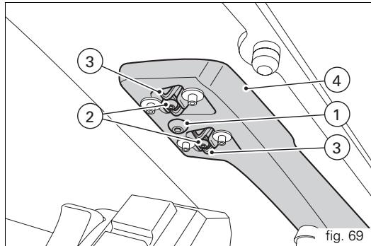
Side fairings
Remove the side fairings using the Allen key located in the.
underseat compartment; unscrew:
the two bolts (1) securing the fairing panels to the brackets; the six bolts (2) securing the fairing panels to the headlight. fairing;
the four bolts (3) securing the fairing panels to the frame; the two bolts (4) located under the fairing that join the right fairing panel to the left fairing panel;
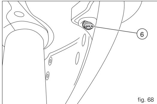
the two bolts (5) securing the fairing panels to the oil cooler; the two bolts (6, fig. 68) securing the front of the fairing to the headlight fairing.


Notes
- Be careful of the splashguard, which is released by the big panel fastening.

Notes
To refit the left fairing panel, lower the sidestand and pass it through the aperture in the panel.
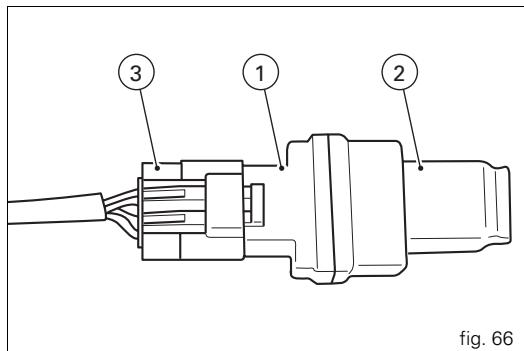
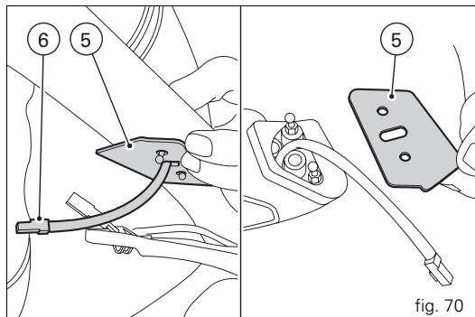
Rearview mirrors
Unscrew the bolts (1) securing the rearview mirror.
Release the pins (2) from the retaining clips (3) attached to the headlight fairing bracket (4). Slip off the rubber covers (5) and disconnect the turn signal wiring connector (6).
Repeat the procedure to remove the other rearview mirror.

Important
On refitting, apply medium-strength threadlocker to reads of the bolts (1).
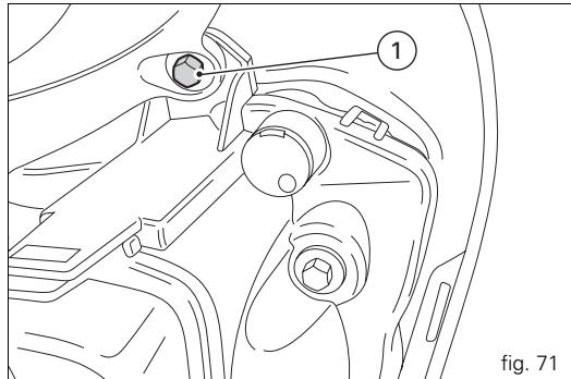
Headlight fairing

Notes
To remove the headlight fairing, first remove the rearmirrors and side fairing panels as described above.
Unscrew the two rear bolts (1) securing the headlight fairing to the headlight support.

Notes
After refitting the headlight fairing, refit the side body s and rear-view mirrors.
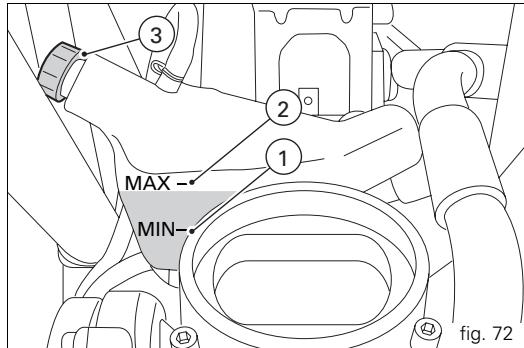
Checking and topping up the coolant level (fig. 72)
Check the coolant level in the expansion reservoir on the right side of the motorcycle. It should be between the two marks (1) and (2). Mark (2) indicates MAX level, and mark (1) indicates MIN level.
Top up if below the MIN level.
Remove the right-hand fairing (page 79).
Unscrew the filler cap (3, fig. 72) and add a mixture consisting of water and antifreeze SHELL Advance Coolant or Glycoshell (35-40% of the volume) up to the MAX mark.
Refit the cap (3) and replace all removed parts.
This type of mixture gives the best operating conditions (the coolant starts to freeze at -20^ / -4^
Cooling circuit capacity: 2.8dm^3 (litres).

Warning
This operation must be carried out with the engine
cold and with the motorcycle vertical and level.
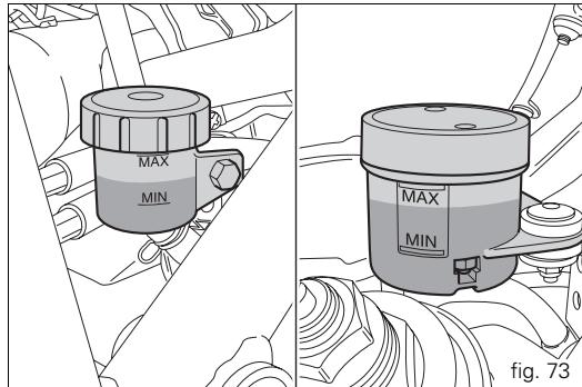
Checking the brake and clutch fluid level
The level must not fall below the MIN mark on the corresponding reservoir (fig. 73) (the figure shows the front and rear brake fluid reservoirs).
If the level is too low, air can get into the circuit, thus impairing the efficiency of the system.
Brake and clutch fluid must be topped up and changed at the intervals specified in the routine maintenance table (see Warranty Booklet) by a Ducati Dealer or Authorized Service Centre.

Important
It is recommended that all brake and clutch hoses be
renewed every 4 years.
Brake system
If there is excessive play at the brake lever or pedal even though the brake pads are still in good condition, contact a Ducati Dealer or Authorized Service Centre to have the system inspected and any air expelled from the circuit.

Warning
3 Brake and clutch fluid can damage paintwork and plastic parts, so avoid contact. Hydraulic fluid is corrosive and can cause damage and injuries. Never mix fluids of different qualities.
Check that the seals are in good condition.
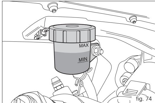
Clutch system
If there is too much play at the clutch lever and the motorcycle jumps or stops when a gear is engaged, this indicates air in the system. Contact a Ducati Dealer or Authorized Service Centre to have the system inspected and the air bled from the system.

Warning
The clutch fluid level in the reservoir tends to rise as the friction material on the clutch plates wears out. Do not exceed the specified level (3 mm above the minimum level).
Checking the brake pads for wear
(fig. 75 and fig. 76)
The brake pads are marked with wear indicators so that they can be checked without removing them from the calipers. If the grooves in the pad friction material are still visible, the pad is still in good condition.

Important
Have the brake pads replaced by a Ducati Dealer or
Authorized Service Centre.
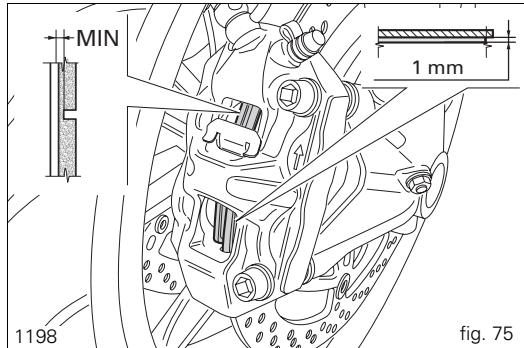
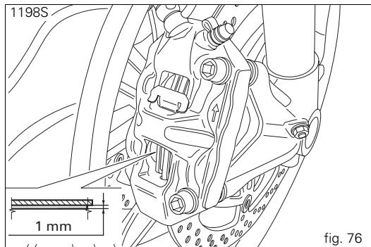
Lubricating cables and linkages
The condition of the outer throttle and choke cables should be checked at regular intervals. The outer cables should show no signs of kinking or cracking. Operate the controls to make sure the inner cables slide smoothly inside the outer cables: if you feel any friction or catching, have the cable replaced by a Ducati Dealer or Authorized Service Centre. To prevent problems, periodically open the twistgrip housing by unscrewing the two bolts (1, fig. 77) and lubricate the ends of each control cable and the races with SHELL Advance Grease or Retinax LX2.

Warning
Close the twistgrip housing carefully, inserting the in the race.
Refit the housing and tighten the bolts (1) to 10Nm .
To ensure smooth operation of the sidestand pivot, remove dirt and apply SHELL Alvania R3 grease to all friction points.
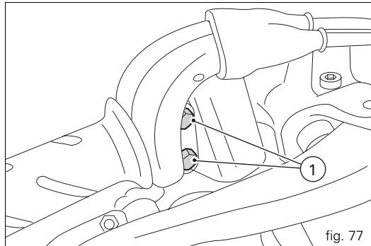
Adjustment of the throttle cable free play
The throttle twistgrip should have free play of 1.5 to 2mm (measured in terms of twistgrip rotation) in all steering positions. If necessary, adjust using the adjusters (1 and 2, fig. 79) located on the steering tube on the right-hand side of the motorcycle. Adjuster (1) is for throttle opening, and adjuster (2) is for throttle closing.
Peel back the sleeves to access the adjusters and slacken the locknuts. Adjust both adjusters by the same amount: turn clockwise to increase free play and anti-clockwise to reduce free play. When finished, tighten the locknuts and replace the sleeves.
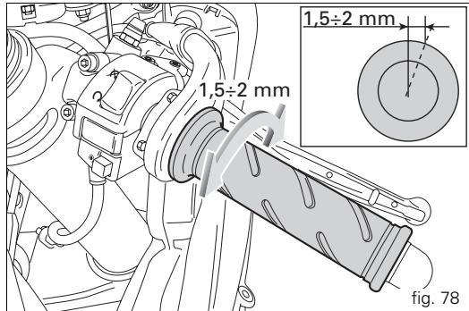
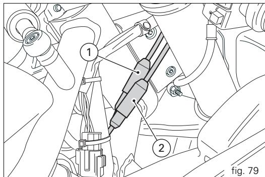
Charging the battery (fig. 80)
Before charging the battery, it is best to remove it from the motorcycle.
Remove the left-hand fairing (page 79), unscrew the bolt (1) and remove the bracket (2). Always disconnect the black negative terminal (-) first, then the red positive terminal (+).

Warning
The battery produces explosive gases: keep it away
from heat sources and flames.
Charge the battery in a well-ventilated area.
Connect the battery charger leads to the battery terminals: red to the positive terminal (+), black to the negative terminal (-).

Important
Connect the battery to the charger before switching
on: failure to do so can result in sparking at the battery terminals, which could ignite the gases inside the cells.
Always connect the red positive terminal (+) first.
Replace the battery in its support (3), then connect the terminals. Apply some grease to the bolts to improve conductivity and fasten the bracket (2) with the bolt (1).

Warning
Keep the battery out of the reach of children.
Charge the battery at 0.9A for 5 to 10 hours.
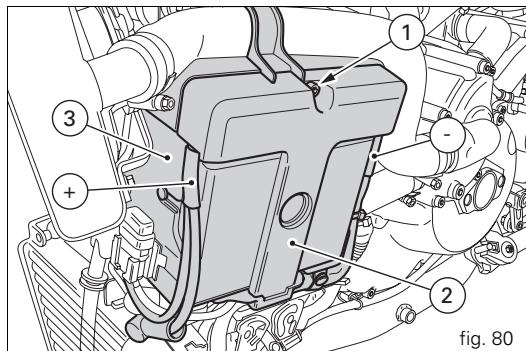
Checking the chain tension (fig. 81)

Important
Have the chain tensioned at a Ducati Dealer or
Authorized Service Centre.
Chain tensioning (on sidestand): hold a rule half way along the bottom run of the chain, push down on the chain and adjust the tension until the distance between the aluminium of the swingarm and the centre of the chain pin is 33 to 35mm

Warning
Correct tightening of the swingarm bolts (1) is
essential to rider and passenger safety.

Important
An incorrectly tensioned chain will cause the rapid
wear of transmission parts.
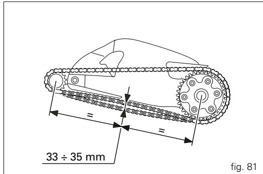
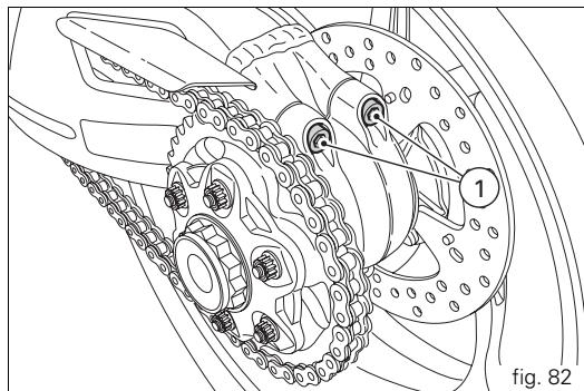
Lubricating the drive chain
The chain fitted on your motorcycle has O-rings that keep dirt out of and lubricant inside the sliding parts.
So as not to damage these seals when cleaning the chain, use special solvents and avoid aggressive washing with high-pressure steam cleaners.
After cleaning, blow the chain dry with compressed air or wipe with an absorbent material, then lubricate each link with SHELL Advance Chain or Advance Teflon Chain.

Important
Using non-specific lubricants may cause severe
damage to the chain and the front and rear sprocket.
Changing the high and low beam bulbs Before replacing a burnt-out bulb, check that the new one complies with voltage and wattage specified in the "Electrical System" paragraph on page 115. Always check that the new bulb works before refitting removed parts. Figure 83 shows the position of the low beam (LO), high beam (HI) and sidelight (1) bulbs.
Headlight
To gain access to the left-hand bulb, remove the cover (2) by pressing the lever (A).
Rotate the locking ring nut (3) of the upper bulb body anticlockwise and extract the burnt-out bulb. Replace with a bulb of equal rating.
On refitting, rotate the locking ring nut (3) clockwise to secure the bulb in place.
The right-hand bulb is replaced in the same way.
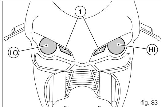
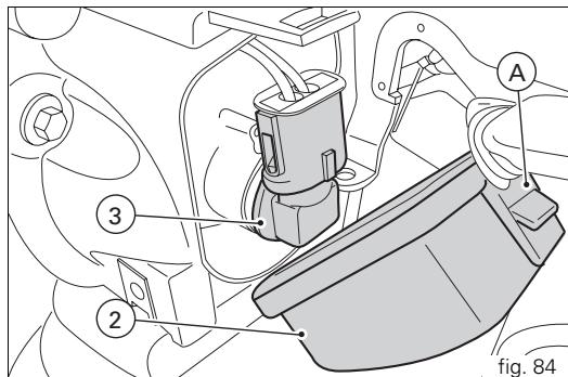
Never touch the transparent body with your fingers or it will blacken resulting in reduced bulb brilliancy.
Refitting
After changing the burnt-out bulb, replace the cover and close it by pressing it against the lever.
Changing the sidelight bulb
To access the sidelights (1), reach your hand inside the headlight support and take the bulb-holders out of their seats. Turn the bulb retaining ring (1) anti-clockwise and remove the burnt-out bulb.
Renew the burnt-out bulb.
On refitting, turn the bulb (1) clockwise to secure it.
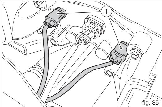
Rear turn signals (fig. 86)
To change the rear turn signal bulbs, rotate the turn signal body (1) by a quarter of a turn so that the lens is facing upwards, and withdraw it from the support.
The bulb has a bayonet-type end fitting: to remove it, push it in and turn it counter-clockwise. Push in the new bulb and turn it clockwise until it clicks into place. Refit the indicator body (3) to its support and rotate it by a quarter of a turn.
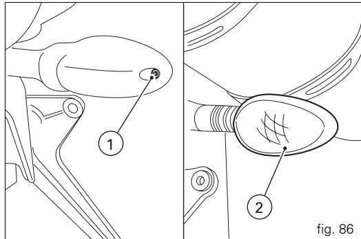
Number plate light (fig. 87)
To access the number plate light bulb, unscrew the bolt (3) securing the cover (4). Remove the bulb and replace it.
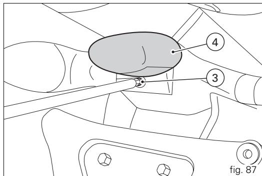
Headlight aim (fig. 88)
To check the headlight aim, place the motorcycle upright with the tyres inflated to the correct pressure and one person sitting astride the motorcycle. The motorcycle should be perfectly vertical, with its longitudinal axis at right angles to a wall or screen at a distance of 10 metres. Draw a horizontal line on the wall at the height of the centre of the headlight and a vertical one in line with the longitudinal axis of the motorcycle. If possible, perform this check in conditions of low ambient light.
Switch on the low beam headlight:
The height of the upper limit between the dark area and the lit area must not be more than nine tenths of the height of the centre of the headlamp from the ground.

Notes
This is the procedure specified by Italian regulations for checking the maximum height of the light beam.
Owners in other countries should adapt this procedure to the regulations in force in the country where the motorcycle is used.
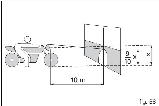
The horizontal position of the left-hand headlight can be adjusted by means of the adjuster screw (1, fig. 89) located behind the headlight. Turn the screw clockwise and the beam will shift to the right; turning the screw anticlockwise will shift the beam to the left.
The vertical position of the left-hand headlight can be adjusted by means of the adjuster screw (2, fig. 89) located behind the headlight. Turn the screw clockwise to lower the beam or anti-clockwise to raise it. Repeat the above procedure to adjust the right-hand headlamp.
Rearview mirror adjustment (fig. 90)
The rearview mirror is adjusted manually by applying pressure at point (A).
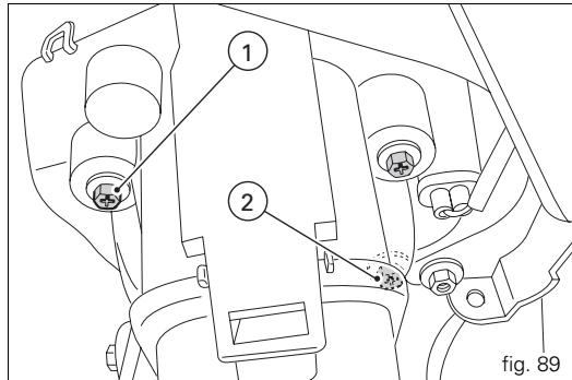
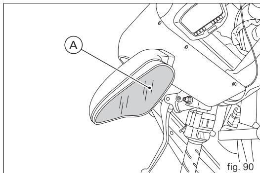
Tubeless tyres
Front tyre pressure:
2.1 bar - 2.3 kg/cm².
Rear tyre pressure:
2.2 bar -2.4kg / cm^2
As tyre pressures are affected by changes in temperature and altitude, check and adjust them whenever you are riding in areas where there are large variations in temperature or altitude.

Important
Check and adjust the pressures with the tyres cold.
To prevent distortion of the front wheel rim, increase tyre pressure by 0.2 to 0.3 bar when riding on bumpy roads.
Tyre repair or replacement (Tubeless)
With minor punctures, tubeless tyres take a long time to deflate, as they tend to hold the air inside. If you find that one of the tyres is slightly deflated, check the tyre for slow punctures.

Warning
Punctured tyres must be renewed.
Replace with tyres of the original brand and type.
Be sure to tighten the valve dust caps securely to prevent leaks while riding. Never fit tyres with inner tubes, as these can cause the tyre to burst suddenly, with possibly serious consequences for the rider and passenger.
After renewing a tyre, the wheel must be balanced.

Important
Do not remove or alter the position of the wheeling weights.

Notes
If tyres need changing, contact a Ducati Dealer or
Authorized Service Centre to make sure wheels are removed and refitted correctly.
Minimum tread depth
Measure the tread depth (S, fig. 91) at the point where the tread is most worn.
It should not be less than 2mm and in any case not less than the legal limit.

Important
Visually inspect the tyres at regular intervals for cracks and cuts, especially on the side walls, and bulges or large stains that indicate internal damage. Replace them if badly damaged.
Remove any stones or other foreign bodies stuck in the tread.
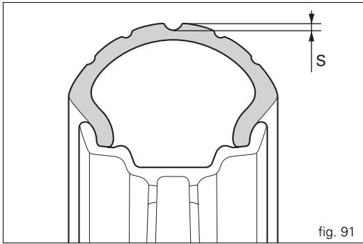
Checking the engine oil level (fig. 92)
Check the engine oil level through the sight glass (1) on the clutch-side crankcase cover. When checking oil level, the motorcycle should be perfectly upright and the engine cold. The oil level should be between the two marks next to the sight glass. Top up the oil level with SHELL Advance Ultra 4, if low. Undo the filler cap (2) and top up to correct level. Replace the filler cap.

Important
To change the engine oil and filters at the intervals specified in the maintenance table in the Warranty Booklet, contact a Ducati dealer or Authorized Service Centre.
Oil viscosity
SAE 15W-50
The other viscosity values shown in the table can be used if the local average temperature is within the limits specified for that oil viscosity.
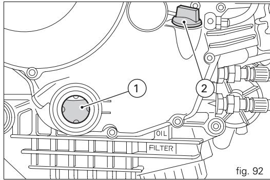
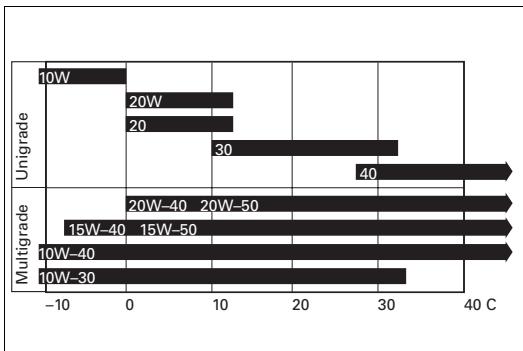
Cleaning and renewing the spark plugs (fig. 93)
Spark plugs are an important part of the engine and should be checked at regular intervals.
The condition of the spark plugs provides a good indication of how well the engine is running.
Have the spark plugs inspected or renewed at a Ducati Dealer or Authorized Workshop. Firstly, they will check the colour of the ceramic insulator of the central electrode: an even brown colour is a sign that the engine is in good running order.

Notes
Secondly, they will check the central electrode for
wear and measure electrode gap. Electrode gap should be: 0.6÷ 0.7 mm.

Important
A gap outside the specified limits will adversely affect
engine performance and may lead to difficult starting or erratic idling.
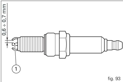
General cleaning
To preserve the original shine on metal surfaces and paintwork, wash and clean your motorcycle at regular intervals depending on the type of use and according to the particular road conditions. Use specific products, where possible biodegradable. Avoid aggressive detergents or solvents.

Important
Do not wash your motorcycle immediately after use, as marks can form due to evaporation of the water on hot surfaces. Never clean the motorcycle using hot or high-pressure water jets. Cleaning the motorcycle with a high-pressure water jet may lead to seizure or serious faults in the front fork, wheel hub assembly, electrical system, front fork seals, air inlets or exhaust silencers, with consequent loss of safety.
If parts of the engine are especially dirty or greasy, use a degreasing agent, avoiding contact with transmission components (chain, front and rear sprockets, etc.). Rinse with warm water and dry all surfaces with chamos leather.

Warning
There may be loss of braking efficiency immediately after washing the motorcycle. Never grease or lubricate the brake discs. This will cause loss of braking efficiency. Clean the discs with an oil-free solvent.
Storing the motorcycle
If the motorcycle is to be left unused for a long period, it is advisable to carry out the following operations first:
clean the motorcycle;
drain the fuel from fuel tank;
pour a few drops of engine oil into the cylinders through the spark plug bores, then turn the engine over by hand a few times to form a protective film of oil on the inner walls of the cylinder;
place the motorcycle on the paddock stand;
disconnect and remove the battery.
If the motorcycle has been left unused for more than a month, the battery should be checked and re-charged if necessary.
Protect the motorcycle with a specific motorcycle cover that will not damage the paintwork or retain moisture.
This type of motorcycle cover is available from Ducati Performance.
Important notes
The legislation in some countries (France, Germany, Great Britain, Switzerland, etc.) sets certain noise and pollution standards.
Periodically carry out the required checks and renew parts as necessary, using Ducati original spare parts, in compliance with the regulations in the country concerned.
Programmed maintenance plan: operations to be carried out by the dealer
| List of operations with frequency (distance or time interval*) Months | km x1000 | 1 | 12 | 24 | 36 | 48 | 60 |
| miles x1000 | 0.6 | 7.5 | 15 | 22.5 | 30 | 37.5 | |
| Months | 6 | 12 | 24 | 36 | 48 | 60 | |
| Change the engine oil | ● | ● | ● | ● | ● | ● | |
| Change the engine oil filter | ● | ● | ● | ● | ● | ● | |
| Clean the engine oil pick-up filter | ● | ||||||
| Check the engine oil pressure | ● | ● | |||||
| Check/adjust the valve clearances (1) | ● | ● | ● | ● | ● | ||
| Check the tension of the timing belts (1) | ● | ● | ● | ||||
| Renew the timing belts | ● | ● | |||||
| Check and clean the spark plugs. Renew if necessary | ● | ● | |||||
| Check and clean the air filter (1) | ● | ● | ● | ||||
| Change the air filter | ● | ● | |||||
| Check throttle body synchronisation and idle speed setting (1) | ● | ● | ● | ● | ● | ● | |
| Check the brake and clutch fluid levels | ● | ● | ● | ● | ● | ● | ● |
| Change the clutch and brake fluid | ● | ||||||
| Check and adjust the brake and clutch control cables | ● | ● | ● | ● | ● | ● | |
| Check/lubricate the throttle/choke cables | ● | ● | ● | ● | ● | ● | |
| Check tyre pressure and wear | ● | ● | ● | ● | ● | ● | ● |
| Check the brake pads. Renew if necessary | ● | ● | ● | ● | ● | ● | ● |
| Check the steering head bearings | ● | ● | |||||
| Check the drive chain tension, alignment and lubrication | ● | ● | ● | ● | ● | ● | ● |
| Check the clutch disc pack. Renew if necessary (1) | ● | ● | ● | ● | ● | ● | |
| Checking the coolant level | ● | ● | ● | ● | ● | ● | |
| Change the coolant | ● | ||||||
| Check operation of electric fans and sealing of coolant circuit | ● | ● | ● | ● | ● | ● | |
| Check the rear wheel cushion drive | ● | ● | |||||
| Check the wheel hub bearings | ● | ● | |||||
| Check the indicators and lighting | ● | ● | ● | ● | ● | ● | |
| Check tightness of nuts and bolts securing the engine to the frame | ● | ● | ● | ● | ● | ● | |
| Check the sidestand | ● | ● | ● | ● | ● | ● | |
| Check tightness of the front wheel axle nut | ● | ● | ● | ● | ● | ● | |
| Check tightness of the rear wheel axle nut | ● | ● | ● | ● | ● | ||
| Check the external fuel hoses | ● | ● | ● | ● | ● | ||
| Change the front fork oil | ● | ||||||
| Check the forks and rear shock absorber for oil leaks | ● | ● | ● | ● | ● | ||
| Check the front sprocket retaining bolts | ● | ● | ● | ● | ● | ||
| General lubrication and greasing | ● | ● | ● | ● | ● | ||
| Check and recharge the battery | ● | ● | ● | ● | ● | ||
| Road test the motorcycle | ● | ● | ● | ● | ● | ● | |
| General cleaning | ● | ● | ● | ● | ● |
- Service operation to be carried out in accordance with the specified distance or time intervals (km, miles or months), whichever occurs first.
(1) Operation to be carried out only at the specified distance intervals.
Programmed maintenance plan: operations to be carried out by the customer
| List of operations with type of intervention (distance or time interval*) | km x1000 | 1 |
| miles x1000 | 0.6 | |
| Months | 6 | |
| Checking the engine oil level | ● | |
| Check the brake and clutch fluid levels | ● | |
| Check tyre pressure and wear | ● | |
| Check the drive chain tension and lubrication | ● | |
| Check the brake pads. If necessary, contact your dealer to renew pads | ● |
- Service operation to be carried out in accordance with the specified distance or time intervals (km, miles or months), whichever occurs first.
Technical data
Overall dimensions (mm) (fig. 94)
Weights
In running order without fuel:
188 kg (1198);
186 kg (1198S).
In running order without liquids and battery:
171 kg (1198);
169kg (1198S).
Fully laden:
390 kg.

Warning
Failure to observe weight limits could result in poor
handling and impair the performance of your motorcycle, and could result in loss of control.
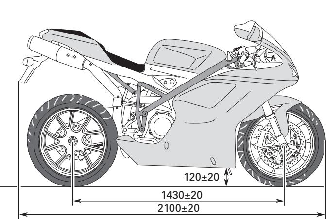
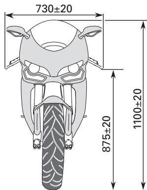
fig. 94
| Fluids and lubricants | Type | |
| Fuel tank, including a reserve of 4 dm3(litres) | Unleaded fuel with 95 fuel octane rating (at least) | 15.5 dm3(litres) |
| Lubrication circuit | SHELL - Advance Ultra 4 | 3.7 dm3(litres) |
| Front/rear brake and clutch circuits | Special hydraulic fluid SHELL Advance Brake Dot 4 | — |
| Protection for electrical contacts | SHELL - Advance Contact Cleaner spray for electrical systems | — |
| Front fork for 1198 only | SHELL - Advance Fork 7.5 or Donax TA | 439 cc (per leg) |
| Front fork for 1198S only | SHELL - Advance Fork 7.5 or Donax TA | 155 mm (each leg) oil level |
| Cooling system | SHELL - Advance Coolant antifreeze or Glycoshell 35-40% + water | 2.3 dm3(litres) |

Important
Do not use additives in fuel or lubricants.
Engine
Longitudinal 90^ "L" twin cylinder, four-stroke.
Bore (mm):
106.
Stroke (mm):
67.9.
Total displacement cm^3
1198.4.
Compression ratio:
12.7 ± 0.5:1
Max power at crankshaft (95/1/EC), kW/HP:
125 kW 170 CV @ 9,750 rpm.
Max torque at crankshaft (95/1/EC):
13.4 kgm/ 131.4 Nm at 8,000 rpm.
Max rotation speed, rpm:
10,700.

Important
Do not exceed the specified rpm limits in any running
conditions.
Timing system
Desmodromic (type) with four valves per cylinder, operated by eight rocker arms (4 opening rockers and 4 closing rockers) and two overhead camshafts. Driven by the crankshaft through spur gears, timing belt pulleys and toothed timing belts.
Desmodromic timing system (fig. 95)
1) Opening (or upper) rocker arm;
2) Opening (upper) shim;
3) Closing (lower) shim;
4) Return spring for lower rocker arm;
5) Closing (lower) rocker arm;
6) Camshaft;
7) Valve.
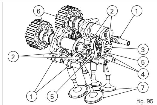
Performance data
Maximum speed in any gear should be reached only after the correct running-in period with the motorcycle properly serviced at the recommended intervals.

Important
Failure to follow these instructions will release
Ducati Motor Holding S.p.A. from any liability for any engine damage or shortened engine life.
Spark plug
Make:
NGK.
Type:
MAR10A-J.
Fuel system
MARELLI indirect electronic injection.
Throttle body diameter:
63.9 mm.
Injectors per cylinder: 1.
Holes per injector: 12.
Fuel supply: 95-98 RON.
Brakes
Front
Semi-floating drilled dual disc.
Braking surface material:
steel.
Flange material:
aluminium.
Disc diameter:
330 mm.
Hydraulically operated by a control lever on right handlebar.
Make of brake calipers:
BREMBO.
Type:
34-4 pistons.
M4-34.
Friction material:
TT 2910.
Master cylinder type:
PR18/19.
Rear
Fixed drilled steel disc.
Disc diameter:
245 mm.
Hydraulically operated by pedal on right side.
Make:
BREMBO.
Type:
P34c pistons.
Friction material:
FERIT I/D 450 FF.
Master cylinder type:
PS 11 b.

Warning
The brake fluid used in the brake system is corrosive.
In the event of accidental contact with eyes or skin, wash the affected area with copious amounts of running water.
Transmission
Dry clutch operated by a control lever on left handlebar. Transmission from engine to gearbox input shaft via spur gears.
Front sprocket/clutch sprocket ratio: 32/59.
6 speed gearbox with constant mesh gears, gearchange pedal on left side of motorcycle.
Final drive ratio:
15/38.
Total gear ratios:
1^st 37/15
2nd 30/17
3^rd 27/20
4^th 24/22
5^th 23/24
6^th 22/25
Drive transmitted from gearbox to rear wheel via chain:
Make:
DID.
Type:
525 HV 2.
Dimensions:
5/8"x5/16".
No. of links:
97+1 joining link.

Important
The above gear ratios are approved and should not be
modified under any circumstances.
However, if you wish to tune up your motorcycle for competitions or special tracks, Ducati Motor Holding S.p.A. will be pleased to provide information about the special ratios available. Please contact a Ducati Dealer or Authorized Service Centre.

Warning
For replacement of the rear sprocket, contact a Ducati
Dealer or Authorized Service Centre. Incorrect replacement of this component could seriously compromise your safety and cause irreparable damage to the motorcycle.
Frame
ALS 450 steel tube trellis frame.
Steering angle (on each side):
24^30^
Wheels
Light-alloy, five spokes (1198).
Light alloy, seven spokes (1198S).
Front
Dimensions:
MT 3.50 × 17^ .
Rear
Dimensions:
MT 6.00× 17^n
Both wheels have removable axles.
Tyres
Front
Radial tubeless tyre.
Dimensions:
120/70-ZR17.
Rear
Radial tubeless tyre.
Dimensions:
190/55-ZR17.
Suspension
Front
Hydraulic upside-down fork provided with external adjusters for rebound, compression and preload (for inner springs of fork legs).
Stanchion diameter:
43 mm with TIO treatment.
Travel along leg axis:
127 mm (1198);
120 mm (1198S).
Rear
Progressive linkage with a rocker arm connecting the frame and upper pivot point of the shock absorber.
The shock absorber is adjustable for rebound, compression, and spring preload. At the bottom pivot point it is connected to a light-alloy swingarm. The swingarm hinges on a pivot shaft that passes through the frame and engine.
This system gives the motorcycle excellent stability.
Shock absorber travel:
59.5 mm.
Wheel travel:
127 mm.
Exhaust system
Equipped with catalytic converter in compliance with Euro 3 emission regulations.
"2 in 1 in 2" lightweight exhaust system, with catalytic converter and lambda sensor. Two stainless steel silencers.
Colour schemes
1198
Ducati anniversary red, code. 473.101 (PPG); Transparent, code. 228.880 (PPG); Racing Black frame, Graphite Grey wheels.
Pearl white, code. 490.019 (PPG);
Transparent, code. 228.880 (PPG);
Racing Black frame, Graphite Grey wheels.
1198S
Ducati anniversary red, code. 473.101 (PPG); Transparent, code. 228.880 (PPG); Bronze frame and wheels.
Midnight black, code 928 D413 (PAL); Transparent, code. 228.880 (PPG); Bronze frame and wheels.
Electrical system
The main components of the electrical system are: headlight:
bulb type: 2 × H11 (12 V-55 W). sidelight:
bulb type: 2 × H16W (12 V-6 W).
Electrical controls on handlebars: turn signals:
Front:LED.
Rear: bulb type: R10W (12 V-10 W) orange.
Horn.
Brake light switches.
Battery, 12 V-10 Ah.
Alternator 12 V-480 W.
Electronic voltage regulator (rectifier), protected by a 30 A fuse located next to the battery (2, fig. 97).
Starter motor, 12V - 0.7kW
Tail light and brake light: LED.
Number plate light:
bulb type: W5W (12 V-5 W).

Notes
See "Replacing low and high beam headlight bulbs"
on page 92 for relevant instructions.
Fuses
The electrical system components are protected by nine fuses located in the fusebox. The fusebox contains seven fuses plus two spares.
Refer to the table below to identify the circuits protected by the various fuses and their ratings in amps.
Key to fusebox (1, fig. 96)
| Pos. | Consumers | Rating |
| 1 | Key-on | 10 A |
| 2 | Lights | 15 A |
| 3 | Consumers | 15 A |
| 4 | Instrument panel | 5 A |
| 5 | Injection | 20 A |
| 6 | Engine Electronic Control Unit | 5 A |
| 7 | Fans | 7.5 A |
The main fuse box (1, fig. 96) is located on the left of the frame. The fuses are accessed by removing the cover, on which are indicated the ampere ratings and fuse positions.
The fuse (2) protects the electronic regulator. Remove the protective cap to access the fuses.
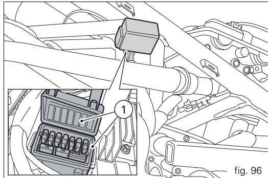
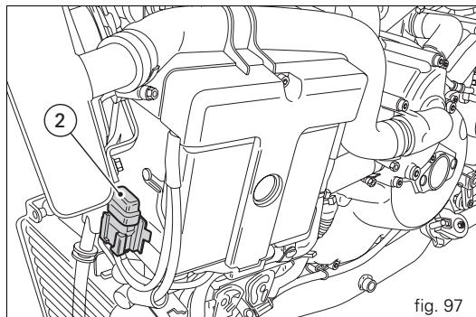
A blown fuse can be identified by a broken filament (3, fig. 98).

Important
To avoid possible short circuits, switch the ignition key to OFF before renewing the fuse.

Warning
Never use a fuse with a rating other than that specified.
Failure to observe this rule may damage the electric system or even cause fire.
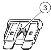
IN GOOD CONDITION
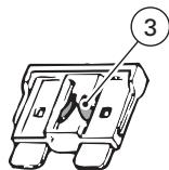
BLOWN
fig. 98
Key to the electrical system/injection system diagram
1) Right-hand handlebar switch
2) Key switch
3) Left cooling fan
4) Right cooling fan
5) Starter motor
6) Starter contactor
7) Battery
8) Regulator fuse
9) Regulator
10) Alternator
11) Rear right turn signal
12) Tail light
13) Number plate light
14) Rear left turn signal
15) Fuel tank
16) Stepper motor
17) Injection relay
18) Self-diagnosis
19) Horizontal cylinder coil
20) Vertical cylinder coil
21) Horizontal cylinder spark plug
22) Vertical cylinder spark plug
23) Horizontal cylinder injector
24) Vertical cylinder injector
25) Throttle position sensor
26) Rpm/timing sensor
27) Coolant temperature sensor
28) Rear speed sensor
29) Sidestand
30) Horn
B Blue
W White
Violet
Bk Black
Y Yellow
R Red
Lb Light blue
Gr Grey
G Green
Bn Brown
0 Orange
P Pink

Notes
The electrical system wiring diagram is at the end of this manual.
Routine maintenance record
| km | Name of Ducati Service | Mileage | Date |
| 1,000 | |||
| 12,000 | |||
| 24,000 | |||
| 36,000 | |||
| 48,000 | |||
| 60,000 |
For United States of America version Only
Reporting of safety defects
If you believe that your vehicle has a defect which could cause a crash or could cause injury or death, you should immediately inform the National Highway Traffic Safety Administration (NHTSA) in addition to notifying Ducati North America. If NHTSA receives similar complaints, it may open an investigation, and if it finds that a safety defect exists in a group of vehicles, it may order a recall and remedy campaign. However, NHTSA cannot become involved in individual problems between you, your dealer, or Ducati North America. To contact NHTSA, you may either call the Auto Safety Hotline toll-free at 1-800-424-9393 (or 366-0123 in Washington, D.C. area) or write to: NHTSA, U.S. Department of Transportation 400 7^th street sw, (NSA-11) Washington, D.C. 20590. You can also obtain other information about motor vehicle safety from the Hotline.
Safety warnings
Traffic Rules vary from jurisdiction to jurisdiction. Know the regulations in your jurisdiction before riding this motorcycle.
Warning
This motorcycle is designed and intended for use on streets and other smooth, paved areas only. Do not use this motorcycle on unpaved surfaces. Such use could lead to upset or other accident.
Noise emission warranty
Ducati Motor S.p.A. warrants that this exhaust system, at the time of sale, meets all applicable U.S. EPA Federal noise standards. This warranty extends to the first person who buys this exhaust system for purposes other than resale, and to all subsequent buyers. Warranty claims should be directed to: Ducati North America, 10443 Bandley Drive, Cupertino, California, 95014 Tel: 001.408.253.0499 - Fax: 001.408.253.4099.
Noise and exhaust emission control system information
Source of Emissions
The combustion process produces carbon monoxide and hydrocarbons. Control of hydrocarbons is very important because under certain conditions, they react to form photochemical smog when subjected to sunlight.
Carbon monoxide does not react in the same way, but is toxic. Ducati utilizes lean carburetor settings and other systems to reduce carbon monoxide and hydrocarbons.
Exhaust Emission Control System
The Exhaust Emission Control System is composed of lean carburetor settings, and no adjustments should be made except idle speed adjustments with the throttle stop screw. The Exhaust Emission Control System is separate from the crankcase emission control system.
Crankcase Emission Control System
The engine is equipped with a closed crankcase system to prevent discharging crankcase emissions into the atmosphere. Blow-by gas is returned to the combustion chamber through the air cleaner and the throttle body. Evaporative Emission Control System California motorcycles are equipped with an evaporative emission control system which consists of a charcoal canister and associated piping. This system prevents the escape of fuel vapors from the throttle body and fuel tank.
Tampering warning
Tampering with Noise Control System Prohibited. Federal Law prohibits the following acts or causing thereof: (1) the removal or rendering inoperative by any person, other than for purposes of maintenance, repair, or replacement, of any device or element of design incorporated into any new vehicle for the purpose of noise control prior to its sale or delivery to the ultimate purchaser or while it is in use; or
(2) the use of the vehicle after such device or element of design has been removed or rendered inoperative by any person.
Among those acts presumed to constitute tampering are the acts listed below:
(1) Removal of, or puncturing the muffler, baffles, header pipes or any other component which conducts exhaust gases. (2) Removal or puncturing of any part of the intake system. (3) Lack of proper maintenance. (4) Replacing any moving part of the vehicle, or parts of the exhaust or intake system, with parts other than those specified by the manufacturer. This product should be checked for repair or replacement if the motorcycle noise has increased significantly through use. Otherwise, the owner may become subject to penalties under state and local ordinances.
Problems that may affect motorcycle emissions
If you are aware of any of the following symptoms, have the vehicle inspected and repaired by your local Ducati dealer. Symptoms: Hard starting or stalling after starting. Rough idle. Misfiring or backfiring during acceleration. After-burning (backfiring). Poor performance (driveability) and poor economy.
Riding safety
The points given below are applicable for every day motorcycle use and should be carefully observed for safe and effective vehicle operation.
A motorcycle does not provide the impact protection of an automobile, so defensive riding in addition to wearing protective apparel is extremely important.
Do not let protective apparel give you a false sense of security. Before changing lanes, look over your shoulder to make sure the way is clear. Do not rely solely on the rear view mirror; you may misjudge a vehicle's distance and speed, or you may not see it at all.
When going up steep slopes, shift to a lower gear so that there is plenty of power to spare rather than overloading the engine.
When applying the brakes, use both the front and rear brakes. Applying only one brake for sudden braking may cause the motorcycle to skid and lose control.
When going down long slopes, control vehicle speed by closing the throttle. Use the front and rear brakes for auxiliary braking.
Riding at the proper rate of speed and avoiding unnecessarily fast acceleration are important not only for safety and low fuel consumption but also for long vehicle life and quieter operation.
When riding in wet conditions or on loose roadway surfaces, the ability to maneuver will be reduced. All of your actions should be smooth under these conditions. Sudden acceleration, braking or turning may cause loss of control. When the roadway is wet, rely more on the throttle to control vehicle speed and less on the front and rear brakes.
The throttle should also be used judiciously to avoid skidding the rear wheel from too rapid acceleration or deceleration. On rough roads, exercise caution, slow down, and grip the fuel tank with your knees for better stability.
When quick acceleration is necessary as in passing, shift to a lower gear to obtain the necessary power.
Do not down shift at too high an r.p.m. to avoid damage to the engine from overreving.
Avoiding unnecessary weaving is important to the safety of both the rider and other motorists.
Do not exceed the legal speed limit or drive too fast for existing conditions. High speed increases the influence of any condition affecting stability and the loss of control.
Operate motorcycle only at moderate speed and out of traffic until you have become thoroughly familiar with its operation and handling characteristics under all conditions. This is a very high performance motorcycle, designed and intended for use by experienced careful riders only!
A new motorcycle must be operated according to a special break-in procedure (see Running in recommendations).

brake, clutch, shifter, throttle controls, correct fuel and oil supply.
Gasoline is extremely flammable and is explosive under certain conditions. Refuell in a well ventilated area with the engine stopped. Do not smoke or allow open flames or sparks when refuelling or servicing the fuel system.
Always close the fuel petcock when the engine is not running to prevent flooding of the throttle body. Do not overfill fuel tank (see instructions page 55).
Motorcycle exhaust contains poisonous carbon monoxide gas. Do not inhale exhaust gases and never run the engine in a closed garage or confined area.
Use only Ducati approved parts and accessories.
This motorcycle was not intended to be equipped with a sidecar or to be used to tow any trailer or other vehicle.
Ducati does not manufacture sidecars or trailers and cannot predict the effects of such accessories on handling or stability, but can only warn that the effects will be adverse and any damage to motorcycle components caused by the use of such accessories will not be remedied under warranty.

Warning
Do not ride the motorcycle with helmets attached to the hook; the helmets could cause an accident by distracting the operator or interfering with normal vehicle operation.
Protective apparel
Always wear a helmet. Most motorcycle accident fatalities are due to head injuries.
For safety eye protection, gloves, and high top, sturdy boots should also be worn.
The exhaust system becomes very hot during operation, never touch the exhaust system. Wear clothing that fully covers your legs. Do not wear loose clothing which could catch on the control levers, footrests, wheels, or chain. Any amount of alcohol will significantly interfere with your ability to safely operate your motorcycle. Don't drink and ride.
Vehicle identification number (VIN);
Every Ducati motorcycle is identified by two identification numbers (see page 9); fig. A specifically shows the frame identification numbers.
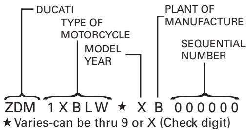
fig.A
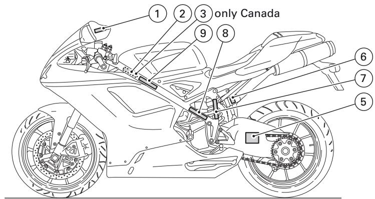
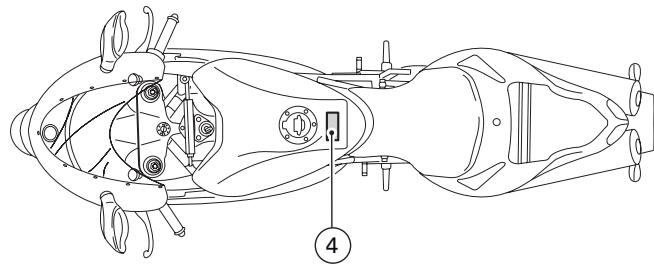
fig.B
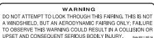
1
Manufactured by DUCATIMOTORHOLDING SPA
DATE:

GVWR: Lbs (kg)
GAWR front: Lbs kg) with tire, RIM at PSI cold.
GAWR rear: Lbs (kg) with tire, RIM at PSI cold.
This vehicle conforms to all applicable Federal Motor Vehicle Safety standards in effect on the date of manufacture shown above. Type classification: Motorcycle
Vehicle I.D. No.:
编号:101
| MANUFACTURED BY/FAIROBIE PAR: DUCATMORHOLDING SPA TYPE OF VEHICLE / TYPE DE VEHICLE: MC GWRN / PBNV *** KG. V.J.N./N.L.: ZDM***** | |||
| CRAFT / FRADE KG | TREMS/PRESIDUALS - BISANTE | COGNITIVE PRESIDUALS / PREDICTED PREDICTIONAL PPEA | |
| *** | ********** | ********** | *** |
| *** | ********** | ********** | *** |
3 (Only Canada)
2
CAUTION
NEVER FILL TANK SO FUEL LEVEL RISES INTO FILLER
NECK, IF TANK IS OVERFILLED, HEAT MAY CAUSE
FUEL TO EXPAND AND FLOW INTO EVaporATIVE
EMISSION CONTROL SYSTEM RESULTING IN HARD
STARTING AND ENGINE HESITATION.
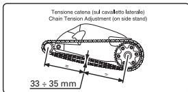
4
5
WARNING CONTAINS HIGHLY COMPRESED GAS, USE ONLY PERFECTLY DRY NITROGEN GAS,OTHER GASES MAY BE INCHANCED OR DO NOT INCINERATE. REFER TO OWNERS MANUAL FOR REGULATING GAS.
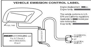
6
7
MOTORCYCLE NOISE EMISSION CONTROL INFORMATION
THIS MOTORCYCLE, MEETS EPA NOISE EMISSION REQUIREMENTS OF dBA AT RPM BY THE FEDERAL TEST PROCEDURE. MODIFICATIONS WHICH CAUSE THIS MOTORCYCLE TO EXCEED FEDERAL NOISE STANDARDS ARE PROHIBITED BY FEDERAL LAW. SEE OWNER'S MANUAL.
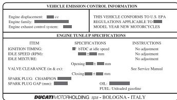
8
California evaporation emission system This system consists of (fig. C):
1) Warn air inlet;
2) Canister;
3) Dell'Orto jet;
4) Fuel tank;
5) Breather pipe;
6) Intake manifolds.

Important
In the event of fuel system malfunction, contact Ducati's authorized Service Centres.
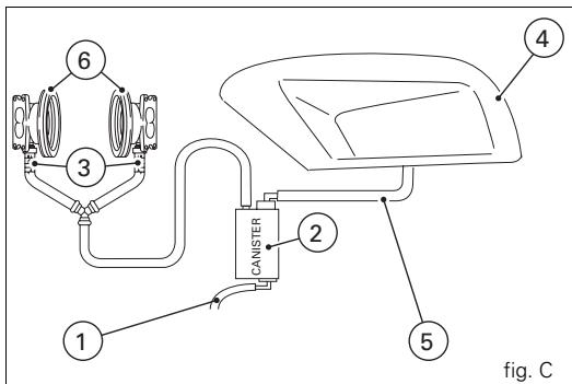
Ducati limited warranty on emission control system
Ducati North America, Inc., 10443 Bandley Drive Cupertino, California, 95014 warrants that each new 1998 and later Ducati motorcycle, that includes as standard equipment a headlight, tail-light and stoplight, and is street legal: A) is designed, built and equipped so as to conform at the time of initial retail purchase with all applicable regulations of the United States Environmental Protection Agency, and the California Air Resources Board; and B) is free from defects in material and workmanship which cause such motorcycle to fail to conform with applicable regulations of the United States Environmental Protection Agency or the California Air Resources Board for a period of use of 30,000 kilometers (18,641 miles) or 5 (five) years from the date of initial retail delivery, whichever first occurs.
I. Coverage
Warranty defects shall be remedied during customary business hours at any authorized Ducati motorcycle dealer located within the United States of America in compliance with the Clean Air Act and applicable regulations of the United States Environmental Protection Agency and the California Air Resources Board. Any part or parts replaced under this warranty shall become the property of Ducati.
In the state of California only, emissions related warranted parts are specifically defined by that state's Emissions Warranty Parts List. These warranted parts are: carburetor and internal parts; intake manifold; fuel tank, fuel injection system; spark advance mechanism; crankcase breather; air cutoff valves; fuel tank cap for evaporative emission controlled vehicles; oil filler cap; pressure control valve; fuel/vapor separator; canister; igniters; breaker governors; ignition coils; ignition wires; ignition points, condensers, and spark plugs if failure occurs prior to the first scheduled replacement, and hoses, clamps, fittings and tubing used directly in these parts. Since emission related parts may vary from model to model, certain models may not contain all of these parts and certain models may contain functionally equivalent parts. In the state of California only, Emission Control System emergency repairs, as provided for in the California Administrative Code, may be performed by other than an authorized Ducati dealer. An emergency situation occurs when an authorized Ducati dealer is not reasonably available, a part is not available within 30 days, or a repair is not complete within 30 days. Any replacement part can be used in an emergency repair. Ducati will reimburse the owner for the expenses, including diagnosis, not to exceed Ducati's suggested retail price for all warranted parts replaced and labor charges based on Ducati's recommended time allowance for the warranty repair and the geographically appropriate hourly labor rate. The owner may be required to keep receipts and failed parts in order to receive compensation.
II. Limitations
This Emission Control System Warranty shall not cover any of the following:
A. Repair or replacement required as a result of
(1) accident,
(2) misuse,
(3) repairs improperly performed or replacements improperly installed,
(4) use of replacement parts or accessories not conforming to Ducati specifications which adversely affect performance and/or
(5) use in competitive racing or related events.
B. Inspections, replacement of parts and other services and adjustments required for routine maintenance.
C. Any motorcycle on which odometer mileage has been changed so that actual mileage cannot be readily determined.
III. Limited liability
A. The liability of Ducati under this Emission Control Systems Warranty is limited solely to the remedying of defects in material or workmanship by an authorized Ducati motorcycle dealer at its place of business during customary business hours. This warranty does not cover inconvenience or loss of use of the motorcycle or transportation of the motorcycle to or from the Ducati dealer. Ducati shall not be liable for any other expenses, loss or damage, whether direct, incidental, consequential or exemplary arising in connection with the sale or use of or inability to use the Ducati motorcycle for any purpose. Some states do not allow the exclusion or limitation of any incidental or consequential damages, so the above limitations may not apply to you.
B. No express emission control system warranty is given by Ducati except as specifically set forth herein. Any emission control system warranty implied by law, including any warranty of merchantability or fitness for a particular purpose, is limited to the express emission control systems warranty terms stated in this warranty. The foregoing statements of warranty are exclusive and in lieu of all other remedies. Some states do not allow limitations on how long an implied warranty lasts so the above limitation may not apply to you. C. No dealer is authorized to modify this Ducati Limited Emission Control Systems Warranty.
IV. Legal rights
This warranty gives you specific legal rights, and you may also have other rights which vary from state to state.
V. This warranty is in addition to the Ducati limited motorcycle warranty.
VI. Additional information
Any replacement part that is equivalent in performance and durability may be used in the performance of any maintenance or repairs. However, Ducati is not liable for these parts. The owner is responsible for the performance of all required maintenance. Such maintenance may be performed at a service establishment or by any individual. The warranty period begins on the date the motorcycle is delivered to an ultimate purchaser.
Ducati North America, Inc.
10443 Bandley Drive
Cupertino, California, 95014
Tel: 001.408.253.0499
Fax: 001.408.253.4099
E-mail: customerservice@ducatiusa.com
Web site: www.ducatiusa.com
Routine maintenance record
| Km | mi | Ducati Service Name | Mileage | Date |
| 1,000 | 600 | |||
| 12,000 | 7,500 | |||
| 24,000 | 15,000 | |||
| 36,000 | 22,500 | |||
| 48,000 | 30,000 | |||
| 60,000 | 37,500 |