S4R S TRICOLORE - Motorcycle DUCATI - Free user manual and instructions
Find the device manual for free S4R S TRICOLORE DUCATI in PDF.
User questions about S4R S TRICOLORE DUCATI
0 question about this device. Answer the ones you know or ask your own.
Ask a new question about this device
Download the instructions for your Motorcycle in PDF format for free! Find your manual S4R S TRICOLORE - DUCATI and take your electronic device back in hand. On this page are published all the documents necessary for the use of your device. S4R S TRICOLORE by DUCATI.
USER MANUAL S4R S TRICOLORE DUCATI
DUCATIMONSTER S4R / S4RS
E
We would like to welcome you among Ducati enthusiasts, and congratulate you for choosing a Ducati motorcycle.
We are sure that you will use your Ducati motorcycle for longer journeys as well as short daily trips, but however you use your motorcycle, Ducati Motor Holding s.p.a wishes you an enjoyable ride.
As part of our continuous effort to improve our service, we advise you to strictly follow the indications given in this manual, especially as regards running-in. In this way, you can be sure your Ducati motorcycle will continue to be a pleasure to ride.
For repairs or advice, please contact one of our authorized service centres.
There is also an information service available to all Ducati owners and enthusiasts for any advice and suggestions you might need.
Enjoy the ride!

Notes
Ducati Motor Holding S.p.A. cannot accept any liability for errors that may have occurred in the preparation of this manual. All information in the manual was valid at the time of going to print. Ducati Motor Holding S.p.A. reserves the right to make any modifications required due to the ongoing development of their products.
For safety and reliability, to avoid invalidating the warranty and to maintain the value of your motorcycle, use only original Ducati spare parts.

Warning
This manual is an integral part of the product and, if ownership is transferred to a third party, must always be passed to the new owner.
Table of contents
E
General indications 6
Warranty 6
Symbols 6
Useful road safety information 7
Riding with a full load 8
Identification data 9
Controls 10
Position of the motorcycle controls 10
Instrument panel 11
The immobilizer system 16
Keys 16
Code card 17
Procedure to override the immobilizer using the throttle
twistgrip 18
Duplicate keys 19
Ignition switch and steering lock 20
Left-hand handlebar switch 21
Clutch lever 21
Right-hand handlebar switch 22
Throttle twistgrip 22
Front brake lever 23
Rear brake pedal 24
Gearchange pedal 24
Adjusting the position of the gearchange pedal 25
Adjusting the position of the rear brake pedal 26
Main components and devices 27
Position on motorcycle 27
Fuel tank filler cap 28
Seat and helmet holder lock 29
Sidestand 30
Shock absorber adjusters 31
Front fork adjusters (MS4R) 33
Front fork adjusters (MS4RS) 35
Adjusting the rear ride height 37
Riding the motorcycle 39
Running-in precautions 39
Pre-ride checks 41
Starting the engine 42
Moving off 44
Braking 44
Stopping the motorcycle 45
Refuelling 45
Parking 46
Toolkit and accessories 47
Main Maintenance Operations 48
Removing the fairing panels 48
Lifting the fuel tank 49
Changing the air filter 50
Checking coolant level 51
Checking the brake and clutch fluid levels 52
Checking the brake pads for wear 53
Adjusting the throttle cable 53
Lubricating cables and joints 54
Charging the battery 55
Checking the chain tension 56
Lubrication of the drive chain 56
Replacing bulbs 57
Headlight aim 61
Tyres 62
Checking the engine oil level 64
Cleaning and renewing the spark plugs 65
General cleaning 66
Storing the motorcycle 67
Important notes 67
Maintenance 68
Programmed maintenance plan: operations to be carried out by the dealer 68
Programmed maintenance plan: operations to be carried out by the dealer 71
Technical data 72
Overall dimensions (mm) 72
Weights 72
Fuel, lubricants and other fluids 73
Engine 74
Timing system 74
Performance data 75
Spark plugs 75
Fuel system 75
Brakes 75
Transmission 76
Frame 76
Wheels 77
Tyres 77
Suspension 77
Exhaust system 78
Available colours 78
Electrical system 78
Routine servicing record 82
For United States of America version Only 83
Reporting of safety defects 83
Safety warnings 83
Noise emission warranty 83
Noise and exhaust emission control system information 83
Tampering warning 84
Riding safety 85
Protective apparel 86
Vehicle identification number (VIN) 86
Label location 87
California evaporation emission system 89
Ducati limited warranty on emission control system 89
Routine maintenance record 92
General indications
E
Warranty
In your own interest, and in order to guarantee product reliability, you are strongly advised to refer to a Ducati Dealer or Authorized Workshop for servicing that requires any particular technical expertise.
Our highly qualified staff have access to the specialised tools required to perform any servicing job to the highest professional standards, using only Ducati original spare parts as the best guarantee for perfect interchangeability, smooth running and long service life.
All Ducati motorcycles come with a "Warranty Booklet". However, the warranty does not apply to motorcycles used in competitions. If any motorcycle part is tampered with, modified, or replaced with parts other than original Ducati spare parts during the warranty period, the warranty will be automatically invalidated.
Symbols
Ducati Motor Holding S.p.A. advises you to read this manual carefully in order to familiarise yourself with your motorcycle. If in doubt, please contact a Ducati Dealer or Authorized Service Centre. The information in this manual will help ensure that your riding experience is trouble-free and enjoyable, and it will help you obtain top performance from your motorcycle for a long time.
This booklet uses a set of symbols with special meanings:

Warning
Failure to comply with these instructions may put you at risk, and lead to severe injury or even death.

Important
There is the possibility of causing damage to the motorcycle and/or its components.

Notes
Additional information about the current operation.
References to the right or left side of the motorcycle assume you are sitting on the seat, facing forward.
Useful road safety information

Warning
Read this section before riding your motorcycle.
Many accidents are the result of the inexperience of the rider. Always make sure you have your licence with you; you need a valid licence that entitles you to ride a motorcycle.
Do not lend your motorcycle to persons that are inexperienced or do not hold a valid licence.
Riders and passengers must always wear appropriate clothing and a safety helmet.
Do not wear loose clothes or accessories that could become tangled in the controls or limit your field of vision.
Never start or run the engine in an enclosed space.
Exhaust gases are poisonous and may lead to loss of consciousness or even death within a short time.
The rider should keep his/her feet on the footrests when the motorcycle is in motion.
Always hold the handlebars firmly with both hands so you will be ready for sudden changes in direction or in the road surface. The pillion passenger should always hold on to the grabhandles under the seat with both hands.
Obey the legal requirements and observe national and local regulations.
Always respect speed limits where these are indicated and always adapt your speed to suit the current visibility, road and traffic conditions.
Always signal your intention to turn or change lane in good time, using the appropriate turn signal indicators.
Be sure you are clearly visible and avoid riding within the blind spot of the vehicle in front of you.
Be very careful at road junctions, or when riding in areas near exits from private land or car parks, or on the slip roads to motorways.
Always turn off the engine when refuelling. Be extremely careful not to spill fuel on the engine or on the exhaust pipe when refuelling.
Do not smoke when refuelling.
While refuelling, it is possible to inhale noxious fuel vapours. Should any fuel drops be spilled on your skin or clothing, immediately wash with soap and water and change your clothing.
Always remove the key if leaving your motorcycle unattended.
The engine, exhaust pipes and silencers stay hot for a long time.

Warning
The exhaust system might still be hot even if the engine is switched off; take special care not to touch exhaust system with any part of your body and do not park the motorcycle next to inflammable material (wood, leaves etc.).
Park your motorcycle where no one is likely to knock against it, and use the side stand.
Never park on uneven or soft ground, or your motorcycle may fall over.
Riding with a full load
Your motorcycle is designed for travelling over long distances with a full load in complete safety.
Even weight distribution is critical for maintaining safety standards, and to avoid getting into difficulties when making sudden manoeuvres or riding on bumpy roads.
E
Information on load capacity
The total weight of the motorcycle in running order with rider, luggage and additional accessories should not exceed 390 kg.
Arrange your luggage or heavy accessories in the lowest possible position and as close to centre of the motorcycle as possible.
Secure the luggage firmly to the motorcycle structure. Luggage incorrectly secured may cause the motorcycle to become unstable.
Never fix bulky or heavy objects to the top yoke or front mudguard, as this would cause dangerous instability.
Do not insert objects into gaps in the frame, where they could interfere with moving parts.
Check that the tyres are inflated to the pressure indicated on page 62 and that they are in good condition.
Identification data
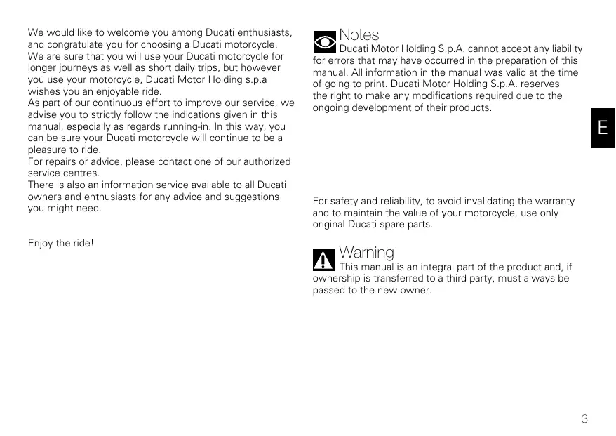
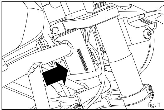
All Ducati motorcycles have two identification numbers, one for the frame (fig. 1) and one for the engine (fig. 2).
Frame number
Engine number

Notes
These numbers indicate the motorcycle model, and should be quoted when ordering spare parts.
natural_image
Mechanical assembly diagram showing a valve inserted into a housing with a black arrow indicating the component (no text or symbols present)
text_image
ZDMXXXXXXXXXX fig. 2Controls
E
Warning
This section shows the position and function of the controls used to drive the motorcycle. Be sure to read this information carefully before you use the controls.
Position of the motorcycle controls (fig. 3)
1) Instrument panel.
2) Ignition switch and steering lock.
3) Left-hand handlebar switch.
4) Clutch lever.
5) Right-hand handlebar switch.
6) Throttle twistgrip.
7) Front brake lever.
8) Gearchange pedal.
9) Rear brake pedal.

text_image
Technical diagram of a motorcycle's rear view with numbered parts for identificationfig. 3
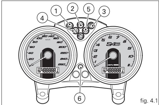
Instrument panel (fig. 4.1 and fig. 4.2)
1) High beam warning light (blue).
Illuminates when the high beam headlight is on.
2) Turn signal warning light ⇌ (green).
Flashes when a turn signal is on.
3) Low fuel warning light 📋 (yellow).
Illuminates when there are approximately 3.5 litres of fuel left in the tank.
4) Neutral light N (green).
Illuminates when the gearbox is in neutral.
5) Engine oil pressure warning light ↗ (red).
Illuminates when engine oil pressure is too low. This light comes on when the ignition is switched to ON and should go out a few seconds after the engine starts.
It may come on briefly if the engine is very hot, but should go out again as engine speed increases.

Important
Do not use the motorcycle if this light stays on,
otherwise the engine could be damaged.
6) Amber warning light
Comes on and flashes when the motorcycle is parked (immobilizer on); also used for immobilizer diagnostics.

Notes
When the immobilizer is activated, the light flashes
for 24 hours after which it goes off, but the immobilizer remains active.
text_image
1 2 3 4 5 6 S485 10 100 100 100 100 100 100 100 100 100 100 100 100 100 100 100 100 100 100 100 100 100 100 100 100 100 18888888888888888888888888888888888888888888888888888888888888888888887) EOBD light 📋 (yellow amber).
Comes on when the engine is locked. Switches off after a few seconds (normally 1.8 - 2 sec.).
8) Speedometer (km/h). Indicates road speed.
a) LCD (1):
- Odometer (km).
Shows total distance travelled. - Trip meter (km).
Shows distance travelled since last reset. - Fuel reserve trip counter.
When the fuel level warning light is on, displays the number of kilometres travelled in reserve.
- Clock
- Coolant temperature
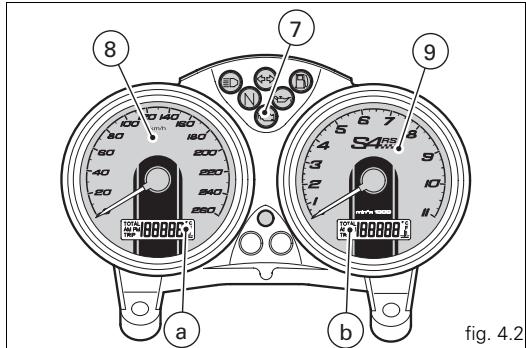
text_image
8 100 140 160 80 180 60 200 40 250 20 340 -250 a b 9 S4 10- 10000000 fig. 4.2LCD functions
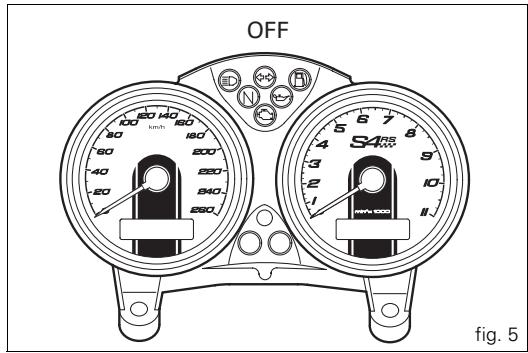
When the key is turned from OFF to ON, the instrument panel runs a check on all instruments (pointers, display, lights) (fig. 5 and fig. 6).
LCD unit functions (1)
By pressing button (B, fig. 6) with the key turned to ON, you can cycle between display of the trip counter and the odometer and, if the fuel level warning light is on, the fuel reserve trip counter.
Resetting the trip meter
If button (B, fig. 6) is held pressed for more than 2 seconds while the TRIP (trip meter) is active, the display is reset (LCD 1).
LCD unit functions (2)
Press button (A, fig. 6) with the key turned to ON to display the clock and coolant temperature.
Setting the clock
Press button (B, fig. 6) for at least 2 seconds and the time will be shown on display (2, fig. 6).
To select AM/PM, press button (B, fig. 6). Press button (B) to select the hour setting function. Press (A) repeatedly to change the hour indication. Press button (B, fig. 6) to enter the minutes setting mode.
Press button (A) to increase the minutes; hold the button pressed for more than 5 seconds to increase the rate of change. Press button (B) to exit the clock setting function.
text_image
OFF S450 S450 200 280 260 240 280 180 160 140 120 100 80 60 40 20 5 4 3 2 1 Fig. 5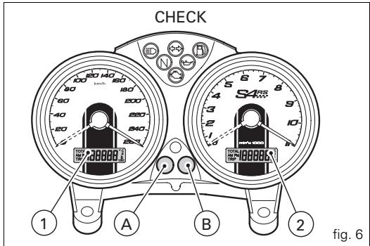
text_image
CHECK 1 A B 2 fig. 6Coolant temperature function
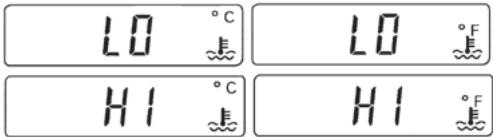
If the coolant temperature falls below 40 ^/104 ^ the word “LO” will be displayed, whereas if the temperature rises above 120 ^/248 ^ , the word “HI” will appear.
Fuel level warning light
When the fuel level warning light illuminates the word "FUEL" appears on display (2, fig. 6) and the fuel reserve trip counter function will be activated and indicate on display (1, fig. 6) the number of kilometres travelled in reserve preceded by the letter "F" (FUEL).
Maintenance indicator function
The “MAInt” message on display (1, fig. 6) indicates that the service interval has been reached: it will be displayed for 5 seconds each time the ignition is switched on. When the “MAInt” message id displayed, contact an authorised dealer or service centre.
Display backlight
Press button (B, fig. 6) within 5 seconds after the ignition key is turned to the ON position to adjust the brightness of the backlight. The brightness changes at each press of the button.

Warning
Any adjustments to the instrument panel must only be carried out when the motorcycle is stationary. Never operate the instrument panel controls while riding.
text_image
LO °C LO °F HI °C HI °FFUEL
NAI nt
Automatic headlight switch-off
This function helps reduce battery use by automatically switching off the headlight.
The device is triggered in two cases:
- in the first case, if you turn the key from OFF to ON and do not start the engine, After 60 seconds the headlight will be deactivated and will only be reactivated the next time the key is turned from OFF to ON or the engine is started.
- in the second case, after normal use of the motorcycle with the lights on, if the engine is killed using the ENGINE STOP switch (1, fig. 12). In this case, 60 seconds after the engine is stopped, the headlight will be turned off and will only be turned on again the next time the engine is started.

Notes
Also during engine starting, the system turns the
headlight off and turns it back on once the engine has started.
The immobilizer system
For additional anti-theft protection, the motorcycle is equipped with an IMMOBILIZER, an electronic system that locks the engine automatically whenever the ignition switch is turned off.
The handgrip of each ignition key contains an electronic device that modulates the output signal from a special antenna in the switch when the ignition is switched On. The modulated signal represents the “password” (which is changed at each start-up) by which the ECU recognizes the ignition key. The ECU will only allow the engine to start if it recognises this password.
Keys (fig. 7)
The owner receives a set of keys, comprising:
- 1 key A (RED)
The red key is a service tool and is part of the motorcycle's immobilizer system.
It contains the code of the immobilizer system and should not be used for normal everyday use of your motorcycle. Your dealer may ask you to produce the red key in order to carry out certain service operations. For security reasons, the red key cannot be replaced. In cases where the red key is required for servicing purposes and the owner is unable to produce it, it will be necessary to renew the motorcycle's electronic control unit, instrument panel and ignition switch assembly, and the cost of these operations will be met by the owner. It is therefore important to keep the red key in a safe place.
- 2 keys B (BLACK)

Warning
The red key (A) has a rubber sleeve to keep it in perfect condition and to prevent contact with other keys. Never remove this protection unless absolutely necessary.
The B keys are the keys for normal use, and are used to:
- start the engine
- open the lock on the fuel tank filler cap
- open the seat lock.
The A key performs all the same functions as the B keys and it can also be used to reset and re-program other black keys if necessary.
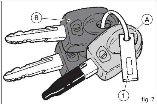
text_image
B A 1 fig. 7
Notes
The three keys have a small tag (1) attached, which shows their identification number.

Warning
Keep the keys separate, and store the tag (1) and key A in a safe place.
It is also advisable to use only one of the black keys to start the motorcycle.
Code card
The keys come with a CODE CARD (fig. 8), which shows: the electronic code (A, fig. 9) to be used if the engine is locked, and if the engine fails to start when the key is at On.

Warning
Keep the CODE CARD in a safe place. It is advisable to always carry the electronic code shown on the CODE CARD with you when using the motorcycle, in case it is necessary to override the engine immobilizer by means of the procedure that uses the throttle twistgrip.
In case of faulty immobilizer system, the following procedure gives the chance to disable “engine lock” function - signalled by illumination of the yellow amber EOBD warning light (7, fig. 4.1).
This operation is only possible with the electronic code shown on the code card.
text_image
code card DUCATY ♥fig. 8
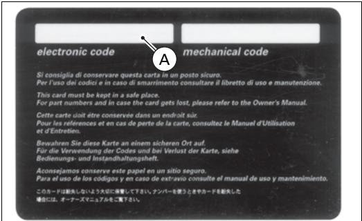
text_image
electronic code A mechanical code Si consiglia di conservare questa carta in un posto sicuro. Per l'uso dei codici e in caso di smarrimento consultare il libretto di uso e manutenzione. This card must be kept in a safe place. For part numbers and in case the card gets lost, please refer to the Owner's Manual. Cette carte doit être conservée dans un endroit suit. Pour les references et en cas de perte de la carte, consultez le Manuel d'Utilisation et d'Entretien. Bewahren Sie diese Karte an einem sicheren Ort auf. Für die Verwendung der Codon und bei Verlust der Karte, siehe Bedienungs- und Instandhaltungshelt. Aconsejamos conserve este papel an un sitio seguro. Para el uso de los códigos y en caso de extravio consulte el manual de uso y mantenimiento. このカードは消失しないよう大成に降着して下さい. ナンバーを使うときやカードを駆失した 場合には、オーアーズチュアルをご覧下さい。fig. 9
Procedure to override the immobilizer using the throttle twistgrip
1) Turn the key to ON, fully open the throttle and hold it open. The EOBD warning light (7, fig. 4.1) goes off after the pre-set time of 8 seconds.
2) Release the throttle twistgrip as soon as the EOBD light goes off.
3) The EOBD light flashes. Now enter the electronic release code shown on the CODE CARD given to the customer when the motorcycle was handed over by the dealer.
4) Count a number of flashes of the EOBD light equal to the first number of the secret code.
Open the throttle twistgrip, hold fully open for 2 seconds, then release it. The digit entered is acknowledged, and the EOBD light comes on and stays on for the pre-set time of 4 seconds. Repeat the operation until you have entered the final digit.
If no operation is performed with the throttle, the EOBD light will flash 20 times and then come on steadily. In this case, repeat the procedure from step (1).
5) When you release the throttle, if the code was entered correctly, the EOBD light flashes to indicate that the engine is unlocked. The EOBD light returns to its normal state (off) after 4 seconds.
6) If the code has NOT been entered correctly, the EOBD light remains lit and the procedure can be repeated as many times as necessary by turning the key to OFF, then re-starting from step (1).

Notes
If you release the twistgrip too soon, the warning light comes on again. Return the ignition key to OFF and repeat the procedure from step (1).
Operation
When the ignition key is turned from ON to OFF, the immobilizer system activates the engine lock. When the ignition key is turned from OFF to ON to start the engine: 1) if the code is recognised, the warning light (6, fig. 4.1) on the instrument panel will flash briefly. This means that the immobilizer system has recognised the code and disabled the engine lock. When you press the START (2, fig. 12) button, the engine will start up.
2) If either the warning light (6, fig. 4.1) or the EOBD light (7, fig. 4.1) remain lit, the code has not been recognized. In this case, it is advisable to turn the ignition key back to OFF and then to ON again. If the engine still does not start, try using another black key. If the engine still does not start, contact the DUCATI Service network.
3) If the warning light (6, fig. 4.1) keeps flashing, it means that an error signal from the immobilizer system has been cleared (e.g. with the override procedure using the throttle twistgrip). Turn the key to OFF and back to ON; the immobilizer light should return to its normal state (see step 1).

Warning
Sharp knocks can damage the electronic
components inside the key.
Always use the same key during the procedure. The use of different keys could prevent the system from recognizing the code in the inserted key.
Duplicate keys
If you need additional keys, contact your DUCATI Service Centre with all the keys you have in your possession and your CODE CARD.
DUCATI Service will program new keys and re-program your original keys (up to a maximum of 8 keys).
DUCATI Service may ask for proof that you are the legitimate owner of the motorcycle.
The codes for any keys not present during the memory programming procedure are cancelled, to ensure that any keys that may have been lost can no longer be used to start the engine.

Notes
If you sell your motorcycle, do not forget to give all keys and the CODE CARD to the new owner.

Ignition switch and steering lock (fig. 10)
This is located in front of the fuel tank and has four positions:
A) ON: enables lights and engine operation;
B) OFF: disables lights and engine operation;
C) LOCK: the steering is locked;
D) P: sidelight and steering lock.

Notes
To move the key to the last two positions, push it in before turning. The key can be removed in positions (B), (C) and (D).
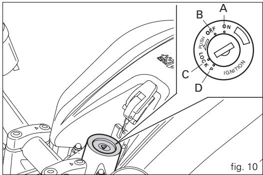
text_image
B A OFF ON PUSH LOCK IGN/TON C D fig. 10Left-hand handlebar switch (fig. 11)
1) Dip switch, two-position light selector switch:
position D = low beam on;
position D = high beam on.
2) Button ⇔→ = three-position turn signal:
centre position = off;
position ⇔ = left turn;
position = right turn.
To cancel the turn signals, press the control switch once it has returned to the central position.
3) Button ▶ = horn.
4) Button D = high beam flasher.
Clutch lever (fig. 11)
Lever (5) disengages the clutch. It features an adjuster knob (6) to alter the distance of the lever from the twistgrip on handlebar.
Lever distance is adjusted by 10 clicks of the knob (6).
Turn the knob clockwise to move the lever away from twistgrip, or counter clockwise to move it closer.
When the clutch lever (5) is operated, drive from the engine to the gearbox and the rear wheel is disengaged.
Correct use of the clutch lever is very important in all riding situations, especially when moving off.
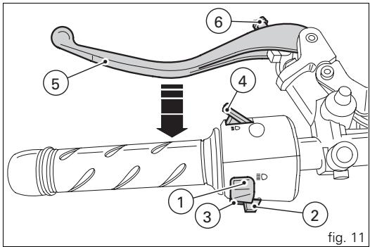
text_image
6 5 4 1 3 2 fig. 11Warning
Adjustment of clutch and brake lever must be carried out when motorcycle is stopped.
Important
Using the clutch properly will prolong the life of the engine and prevent any damage to components in the transmission.
Notes
The engine can be started with the sidestand down and the gearbox in neutral. If starting with a gear engaged, pull in the clutch lever (in this case the sidestand must be up).
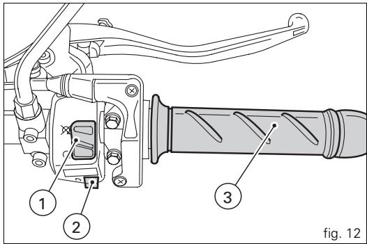
Right-hand handlebar switch (fig. 12)
1) ENGINE STOP switch, with two positions:
position ○ (RUN) = run;
position ☒ (OFF) = stop engine.
E
Warning
This switch is mainly intended for use in emergencies when you need to stop the engine quickly. After stopping the engine, return the switch to the ○ position to enable starting.
Important
Travelling with the headlight, switching off the engine with switch (1) and leaving the ignition key in the ON position can drain the battery, as the headlight remains on.
2) Button Ⓐ = engine start.
Throttle twistgrip (fig. 12)
The twistgrip (3) on the right handlebar opens the butterfly valves in the throttle body. When released, the twistgrip returns automatically to the initial position (idling speed).
text_image
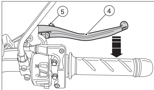
1 2 3 fig. 12Front brake lever (fig. 13)
Pull in the lever (4) towards the twistgrip to operate the front brake. The system is hydraulically assisted and you only need to pull the lever gently.
The brake lever has a wheel (5) for adjusting the distance between lever and twistgrip on the handlebar.
Lever distance is adjusted by 10 clicks of the knob (5).
Turn the knob clockwise to move the lever away from twistgrip, or counter clockwise to move it closer.

Warning
Before using these controls, read the instructions on page 44.
text_image
Technical diagram of a vehicle's steering wheel assembly with numbered parts and directional arrow indicating motionfig. 13
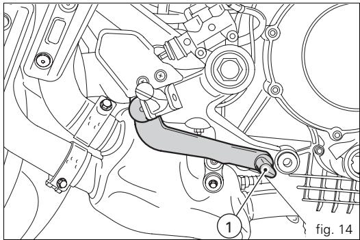
Rear brake pedal (fig. 14)
Push down on the pedal (1) with your foot to operate the rear brake.
The system is controlled hydraulically.
Gearchange pedal (fig. 15)
The gearchange pedal has a central position N, with automatic return, and two directions of movement: down = push down on the pedal to engage 1^st gear and to shift down. At this point the N warning light on the instrument panel will go off;
up = lift the pedal to engage 2^nd gear and then 3^rd , 4^th , 5^th and 6^th gears.
Each time you move the pedal you engage the next gear, one gear at a time.
natural_image
Mechanical assembly diagram showing a lever mechanism with no visible text or symbols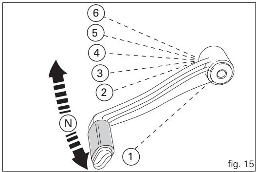
text_image
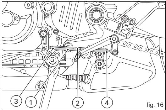
6 5 4 3 2 N 1 fig. 15Adjusting the position of the gearchange pedal (fig. 16)
The gear change pedal position relative to the footrest may be adjusted to suit rider preferences.
To adjust the position, proceed as follows:
Apply a wrench to the flats (2) to hold the tie-rod (1) and loosen the lock nuts (3) and (4).

Notes
The locknut (3) has a left-hand thread.
Turn the rod (1) to move the gearchange pedal to the required position.
Tighten the two lock nuts onto the tie-rod.
text_image
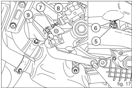
3 1 2 4 fig. 16Adjusting the position of the rear brake pedal (fig. 17)
The position of the rear brake pedal in relation to the footrests can be adjusted to suit the preferred riding position.
To adjust the position of the rear brake pedal, proceed as follows:
Loosen the locknut (5).
Turn the pedal travel adjustment bolt (6) until the pedal is in the desired position.
Tighten the locknut (5).
Operate the pedal by hand to check that there is 1.5 - 2 mm of freeplay before the brake bites.
If not, adjust the length of brake master cylinder pushrod as follows:
Slacken off the locknut (7) on the pushrod.
Screw the rod (8) into the clevis (9) to increase play, or unscrew the rod to reduce it.
Tighten the locknut (7) and recheck the pedal freeplay.
text_image
7 8 9 6 5 fig. 17Main components and devices
Position on motorcycle (fig. 18)
1) Fuel tank filler cap.
2) Seat lock.
3) Helmet cable pin.
4) Passenger grabhandle.
5) Sidestand.
6) Rearview mirrors.
7) Rear shock absorber adjusters.
8) Front fork adjusters.
9) Tank support strut.
10) Seat cover
11) Fuel tank release lever.
12) Catalytic converter.
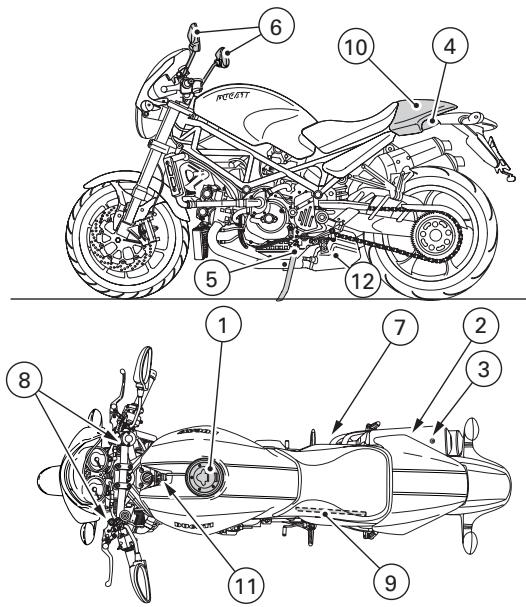
text_image
6 10 4 5 12 7 2 3 8 11 9fig. 18
Fuel tank filler cap (fig. 19)
Opening
Raise the cover (1) and insert the key into the lock. Give the key a 1/4 turn clockwise to unlock. Lift the cap.
Closing
Close the cap with the key inserted and push it into its seat. Turn the key anticlockwise to the initial position and remove it. Replace the lock cover (1).

Notes
The cap can only be closed with the key inserted.

Warning
Always make sure you have properly closed the fuel filler cap after refuelling (see page 45).
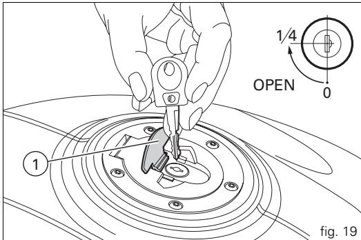
text_image
1/4 OPEN 0 fig. 19Seat and helmet holder lock (fig. 20 and fig. 21)
Opening
Insert the key in the lock and turn it clockwise to release the seat from the frame. Pull the seat backwards to release it from the front catches.
The helmet cable (1) is located at the rear of the compartment under the seat (see page 47). Pass the cable through the helmet and insert the end of the cable in the pin (2). Leave the helmet hanging and refit the seat to hold it in place.

Warning
This device protects the helmet against theft when the motorcycle is parked. Do not leave the helmet attached in this way when riding the motorcycle, as it can interfere with your movements and cause loss of control of the motorcycle.
Closing
Make sure all parts are correctly arranged and secured in the underseat compartment. Insert the front ends of the seat base under the U bolt in the frame, then push the rear end of the seat until you hear the bolt in the lock click into place. Check that the seat is firmly secured to the frame and remove the key from the lock.
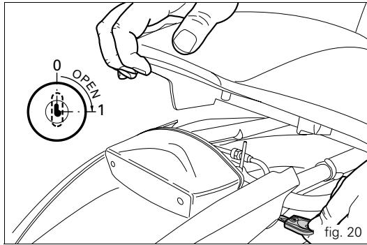
text_image
OPEN 1 0 fig. 20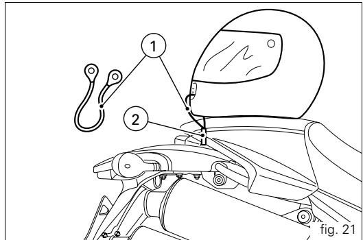
text_image
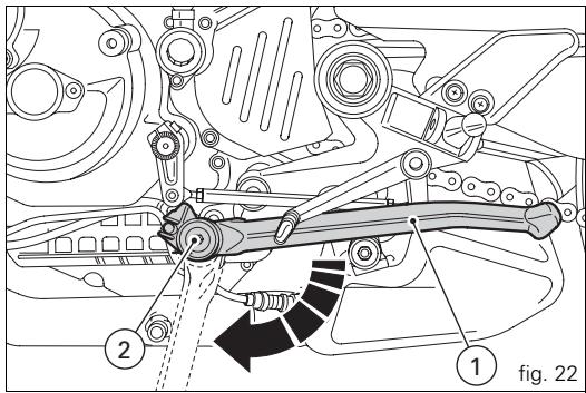
① ② fig. 21Sidestand (fig. 22)

Important
Before lowering the sidestand, check that the ground is sufficiently even and hard.
Do not park on soft ground, gravel or on asphalt softened by the sun etc. or the motorcycle may fall over.
When parking on a slope, always park with the rear wheel on the downhill side.
To lower the sidestand, hold the motorcycle handlebars with both hands and push down on the stand (1) with your foot until it is fully extended. Tilt the motorcycle until the sidestand is resting on the ground.

Warning
Do not sit on the motorcycle when it is supported on the sidestand.
To raise the side stand to the rest position (horizontal position), tilt the motorcycle to the right and, at the same time, raise the stand (1) with your foot.

Notes
It is advisable to check periodically that the stand mechanism (consisting of two springs, one inside the other) and safety sensor (2) are working properly.

Notes
The engine can be started with the sidestand down and the gearbox in neutral. If starting with a gear engaged, pull in the clutch lever (in this case the sidestand must be up).
text_image
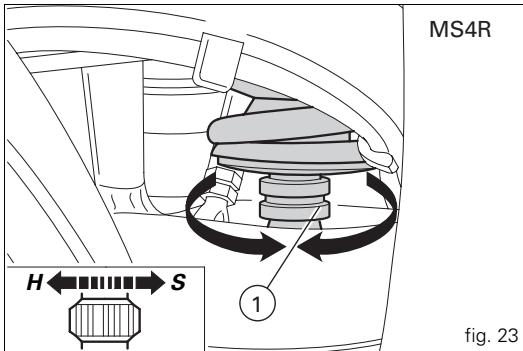
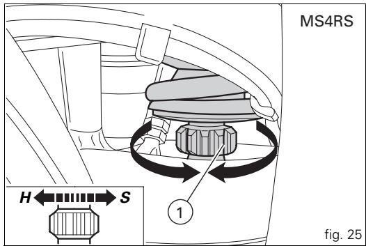
1 2 fig. 22Shock absorber adjusters (fig. 23, fig. 24, fig. 25 and fig. 26)
The rear shock absorber has external adjusters that enable you to adjust your motorcycle suspension to suit the load conditions.
The adjuster (1 fig. 23 and fig. 25) located on the lower end of the shock absorber near where it is attached to the swingarm serves to adjust rebound damping.
Adjuster (2 fig. 24 and fig. 26) on the rear shock absorber expansion reservoir is used to adjust compression damping. Turn the adjusters (1 and 2) clockwise to increase damping, or counterclockwise to reduce damping.
STANDARD setting (MS4R):
starting with the adjusters rotated fully clockwise, turn adjuster (1) 12 clicks and adjuster (2) 12 clicks.
Spring preload: 19 mm.
STANDARD setting (MS4RS):
starting with the adjusters rotated fully clockwise, turn adjuster (1) 10 clicks and adjuster (2) 12 clicks.
Spring preload: 11 mm.
The two nuts (3 fig. 24 and fig. 26) on the upper part of the shock absorber serve to adjust the preload on the external spring.
To change spring preload, slacken off the upper ring nut. Then tighten or loosen the lower ring nut to increase or decrease spring preload as required. Once the desired spring preload has been set, lock down the upper ring nut.
text_image
MS4R H←→S 1 fig. 23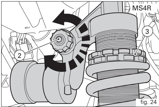
text_image
MS4R 3 2 fig. 24

Warning
Use a pin wrench to turn the preload adjusting nut.
Take special care when turning the nut, to avoid injuring your hand by striking it violently against other parts of the motorcycle if the wrench suddenly slips off the nut while turning.

Warning
The shock absorber is filled with gas under pressure and may cause severe injury if dismantled by untrained persons.
If you plan to carry a passenger and luggage, adjust the rear shock absorber spring load to the maximum setting to improve the handling characteristics of the motorcycle and to avoid the possibility of ground contact. It may also be necessary to adjust the rebound damping accordingly.
text_image
MS4RS H ← S 1 fig. 25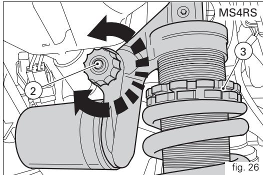
text_image
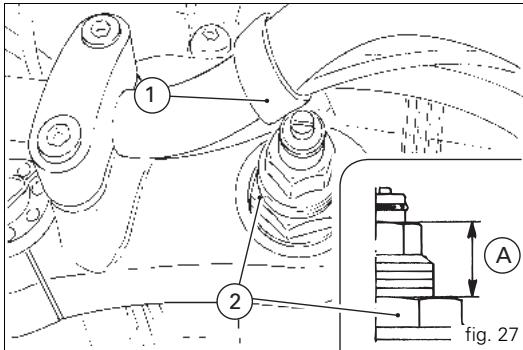
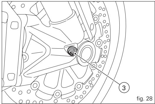
MS4RS 2 3 fig. 26Front fork adjusters (MS4R) (fig. 27 and fig. 28)
The front forks can be adjusted for both rebound damping and compression damping.
The settings are adjusted by way of external adjuster screws:
1) (fig. 27) to adjust rebound damping;
2) (fig. 27) to adjust spring preload;
3) (fig. 28) to adjust compression damping.
To adjust the rebound damping setting, turn the adjuster (1) on the top of each fork leg with a flat screwdriver. To turn the adjuster (3, fig. 28), insert a screwdriver through the base of the fork tube and the hole in the wheel axle as shown.
Adjusters (1) and (3) have click positions corresponding to different damping settings.
The stiffest damping setting is obtained with the adjuster turned fully clockwise fully to the "0" position.
Start with this position and turn counterclockwise. Count the screw clicks, which correspond to position 1, 2 and so forth.
text_image
1 2 A fig. 27The STANDARD positions are as follows, from the fully closed position:
| compression: | 1 turn |
| rebound: | 11 clicks |
| Spring preload (A, fig. 27): | 11 mm |
To change the spring preload for each fork leg, turn the adjuster (2) with a 22 mm hex spanner.

Important
Adjust both fork legs to same setting.
text_image
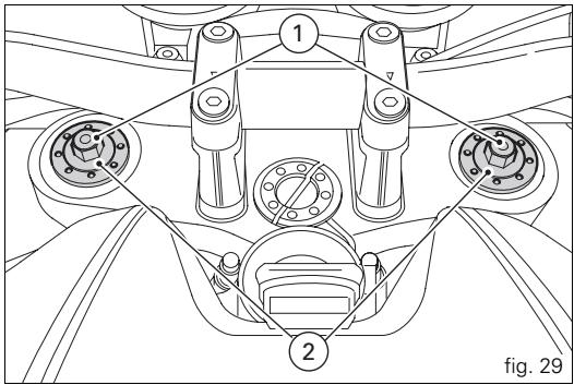
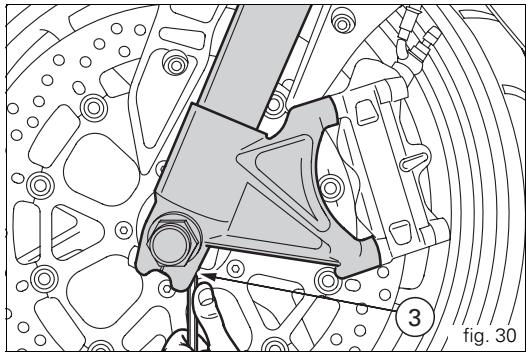
fig. 28 3Front fork adjusters (MS4RS) (fig. 29 - fig. 30)
The front forks can be adjusted for both rebound damping and compression damping.
The settings are adjusted by way of external adjuster screws:
1) (fig. 29) to adjust rebound damping;
2) (fig. 29) to adjust spring preload;
3) (fig. 30) to adjust compression damping.
Turn adjuster (1) at the top of each fork leg with a 3 mm Allen wrench to adjust the rebound damping.
To turn the adjuster (3, fig. 30) insert a 3 mm Allen key through the hole as shown in figure 27. Turn the adjuster screws (1 and 3) while counting the number of clicks; each click corresponds to a damping setting. The stiffest damping setting is obtained with the adjuster turned fully clockwise fully to the "0" position.
Start from this position and turn the adjuster anti-clockwise while counting the number of clicks, which correspond to position "1", "2" and so forth.
text_image
1 7 2 fig. 29Standard settings:
compression: 12 clicks;
rebound: 10 clicks.
Spring preload (fig. 29): 19 mm.
To change the spring preload for each fork leg, turn the adjuster (2) with a 22 mm hex spanner.
E

Important
Adjust both fork legs to same setting.
natural_image
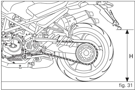
Technical line drawing of a mechanical assembly with no visible text or symbolsAdjusting the rear ride height (fig. 31 - fig. 32 - fig. 33)
The standard ride height setting is the result of tests carried out in a wide variety of conditions by our technical staff. Modifying the frame geometry is a very critical operation, and can be dangerous if carried out by untrained persons. Before changing the standard setting, measure the reference value (H, fig. 31).
The rider can adjust the rear ride height to suit his/her needs by changing the working position of the rear shock absorber. To alter the eye to eye length of the tie-rod (1), slacken the locknuts (3).

Notes
Note that the lower nut (3) has a left-hand thread.
Rotate the tie-rod (2) with an open-ended wrench.
Once the tie-rod length is adjusted correctly, tighten the nuts (3) to 25 Nm.

Warning
The length of the tie-rod (2) between the centres of the two eyes (1) should not exceed 272 mm.
text_image
H fig. 31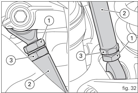
text_image
1 2 3 2 1 3 fig. 32The maximum distance that the UNIBALL end fitting (A) can be unscrewed from the tie-rod body is 5 threads, or 7.5 mm (B).
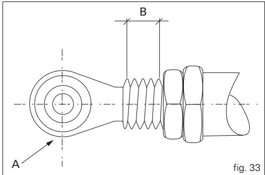
text_image
A B fig. 33Riding the motorcycle
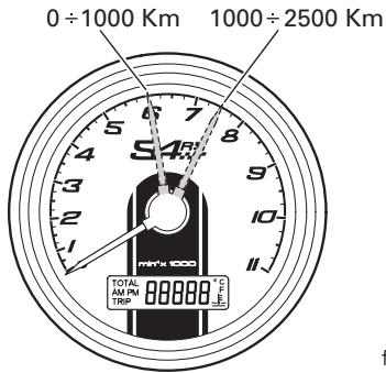
Running-in precautions (fig. 34)

Important
Throughout the running-in period, be careful to stick to the recommended maintenance schedule and periodic service intervals indicated in the warranty booklet. Failure to follow these instructions will release Ducati Motor Holding S.p.A. from any liability for any engine damage or shortened engine life.
Max. engine speed
Rpm limits to be observed during the running-in period and in normal use:
1) Up to 1000 km;
2) From 1000 to 2500 km.
Up to 1000 km
During the first 1000 km, keep an eye on the tachometer.
The revs should never exceed:
6,000 rpm.
During the first hours of riding, it is advisable to continuously vary the load on the engine and the rpm, though still keeping within the above limits.
For this reason, roads with numerous bends and hilly areas are ideal for running in the engine, brakes and suspension.
For the first 100 km, use the brakes gently. Do not brake violently or keep brake applied for too long. This will enable a correct break-in of friction material on brake pads against brake discs.
To allow all the mechanical moving parts in the motorcycle to adapt to one another, and to avoid shortening the life of the main engine components, it is advisable to avoid sudden acceleration and running the engine at high rpm for too long, especially uphill.
It is also advisable to check the drive chain frequently and ensure that it is lubricated as required.
From 1000 to 2500 km
At this point, you can ask for more power from the engine, being careful, however, never to exceed: 7,500 rpm.
Keeping to the running-in recommendations will ensure longer engine life and reduce the need for overhauls and re-tuning.
text_image
0 ÷ 1000 Km 1000 ÷ 2500 Km S47 MIN's 1000 TOTAL AM PRTR 88888 °F TRIP ffig. 34
Pre-ride checks

Warning
Failure to carry out these checks before starting may result in damage to the motorcycle and injury to rider.
Before starting, check the following points:
Fuel level in the tank
Check the fuel level in the tank. Re-fuel if necessary (page 45).
Engine oil level
Check the oil level in the sump through the sight glass.
Top up with recommended oil if needed (page 64).
Brake and clutch fluid
Check the fluid levels in the respective reservoirs.
Coolant
Check coolant level in the expansion reservoir. Top up if necessary (page 51).
Tyre condition
Check the pressure and condition of the tyres (page 62).
Controls
Operate the brake, clutch, gearchange and throttle controls (lever, pedal and twistgrip) and check that they function correctly.
Lights and indicators
Check that lights, indicators and horn are working properly. Replace any burnt-out bulbs (page 57).
Key locks
Check that the fuel filler cap and the seat are locked.
Sidestand
Make sure the sidestand operates smoothly and is in the correct position (page 30).

Warning
If there are any faults or malfunctions, do not start the motorcycle and contact your DUCATI Dealer or Authorized Service Centre.
Starting the engine

Warning
Before starting the engine, familiarise yourself with the controls you will need to use when riding. Never start or run the engine in enclosed space. Exhaust gases are toxic and may lead to loss of consciousness or even death within a short time.
1) Turn the ignition key to ON (fig. 35). Check that both the green light N and the red light 📋 on the instrument panel come on.

Important
The oil pressure warning light should go out a few seconds after the engine has started (page 11).

Warning
The sidestand should be in the rest position (horizontal), otherwise the safety sensor prevents the engine starting.

Notes
The engine can be started with the sidestand down and the gearbox in neutral. If starting with a gear engaged, pull in the clutch lever (in this case the sidestand must be up).
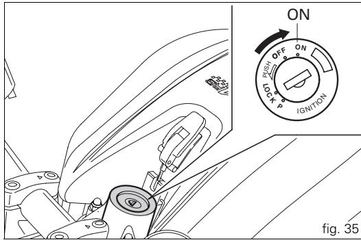
text_image
ON OFF PUSH LOCK IGNITION fig. 352) Check that the stop switch (1, fig. 36) is positioned to Ⓞ (RUN), then press the starter button (2).
This model features servo-assisted starting.
Press and immediately release the start button (2) to use the servo-assisted engine starting function.
When you press button (2) the starter motor runs automatically for a period of time that varies according to the engine temperature.
The system disengages the starter motor as soon as the engine starts.
If the engine fails to start, wait at least 2 seconds before pressing the start button (2) again.
Allow the engine to start without turning the throttle twistgrip.

Important
Do not rev the engine when cold. Allow some time for the oil to warm up and reach all points that need lubricating.
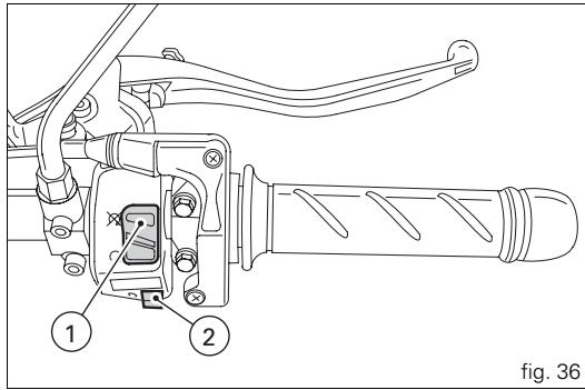
text_image
① ② fig. 36Moving off
1) Disengage the clutch by squeezing the clutch lever.
2) Push down the gearchange lever firmly with the tip of your foot to engage first gear.
3) Raise the engine revs by turning the throttle twistgrip while gradually releasing the clutch lever. The motorcycle will start moving.
4) Release the clutch lever completely and accelerate.
5) To change to second gear, close the throttle to reduce the engine revs, disengage the clutch, lift the gearchange lever and release the clutch lever.
To change down, proceed as follows: release the twistgrip, disengage the clutch, briefly accelerate the engine to allow the gears to synchronize, shift down and release the clutch. Use the controls intelligently and opportunely: when riding uphill, change down immediately when the motorcycle begins to slow down, to avoid abnormal stresses on the motorcycle structure as well as on the engine.

Important
Avoid sudden acceleration, as this may lead to
misfiring and transmission snatching. The clutch lever should not be held in longer than necessary after a gear is engaged, otherwise friction parts may overheat and wear out.
Braking
Slow down in time, change down to use the engine brake, then apply both brakes. Pull in the clutch lever before the motorcycle comes to a stop to prevent the engine stalling.

Warning
Use both the brake lever and the brake pedal for effective braking. Using only one of the brakes will give you less braking power.
Never use the brake controls harshly or suddenly as you may lock the wheels and lose control of the motorcycle. When riding in the rain or on slippery surfaces, braking capacity is significantly reduced. Always use the brakes very gently and carefully when riding under these conditions. Any sudden manoeuvres may lead to loss of control. When riding down long, steep downhill slopes, change down to use engine braking. Apply the brakes intermittently for brief periods only. Keeping the brakes applied continuously causes the friction material to overheat and dangerously reduces braking effectiveness. Under-inflated tyres reduce braking efficiency and may adversely affect handling and road-holding on bends.
Stopping the motorcycle (fig. 37)
Reduce speed, change down and release the throttle twistgrip. Change down to engage first gear and then neutral. Apply the brakes and bring the motorcycle to a complete stop. To switch the engine off, simply turn the key to OFF.

Important
Do not leave the key in the ON position when the engine
is stopped as this could damage electrical components.
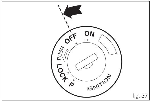
text_image
OFF ON PUSH LOCK P IGNITION fig. 37Refuelling (fig. 38)
Do not overfill the tank when refuelling. The fuel level should always be below the rim of the filler recess.

Warning
Use fuel with low lead content and an original
octane number of at least 95.
Check that no fuel is trapped in the filler cap recess.
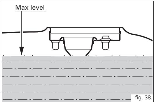
text_image
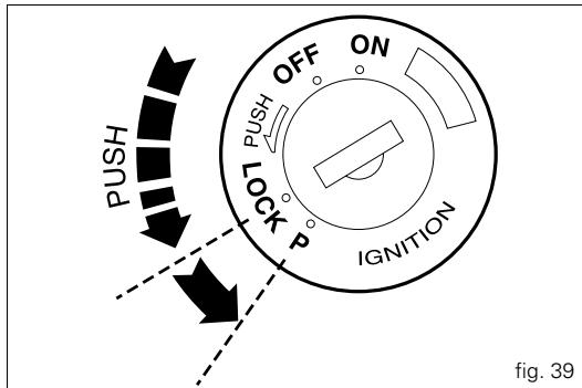
Max level fig. 38Parking (fig. 39)
Stop and park the motorcycle on the side stand (see page 30). To avoid theft, turn the handlebar fully left and block it by pushing in the ignition key and turning it to the LOCK position. If you park in a garage or other indoor area, make sure that there is proper ventilation and that the motorcycle is not near a source of heat.
If necessary, you can leave the side lights on by turning the key to position P.

Important
Do not leave the key at P for long periods or the battery will run down. Never leave the motorcycle unattended with the ignition key inserted.

Warning
The exhaust system might still be hot even if the engine is switched off; take special care not to touch exhaust system with any part of your body and do not park the motorcycle next to inflammable material (wood, leaves etc.).

Warning
Using padlocks or other locks designed to prevent movement of the motorcycle (such as brake disc locks, rear sprocket locks, and so on) is very dangerous, and may impair motorcycle operation and the safety of rider and passenger.
text_image
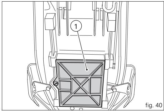
OFF ON PUSH PUSH LOCK P IGNITION PUSH fig. 39Toolkit and accessories
The following accessories are stowed under the seat: use and maintenance manual; helmet fastening cable; toolkit for routine maintenance operations and checks.
To access the compartment, you need to remove the seat (page 29) and remove the cover (1, fig. 40) unscrewing the special screw with a coin.
The toolkit (fig. 41)
Contains:
2) spark plug wrench;
3) tommy bar for spark plug wrench;
4) double-ended screwdriver;
5) helmet fastening cable.
text_image
① fig. 40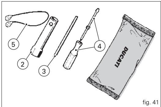
text_image
5 2 3 4 BUCAN fig. 41Main Maintenance Operations
E
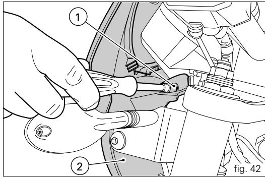
Removing the fairing panels (fig. 42)
Some parts of the motorcycle fairing have to be removed for certain maintenance or repair operations.

Warning
Failure to replace or incorrect refitting of any of the components removed could cause parts of the fairing to come loose when riding and the consequent loss of control of the motorcycle.
Removing the headlight shell
Unscrew and remove the two bolts (1) securing the headlight shell to the headlight support.

Notes
Be careful not to lose the nuts for the bolts (1)
located on the inside of the headlight shell.
Remove the headlight shell (2).
text_image
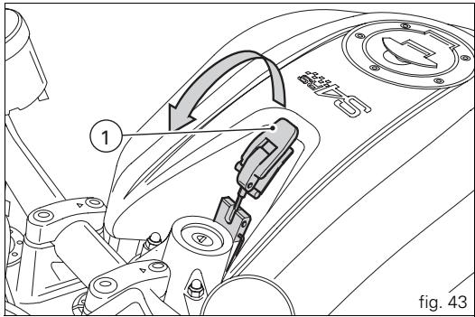
Technical diagram showing a hand using a tool to adjust or install components, labeled with parts 1 and 2, and figure number fig. 42.Lifting the fuel tank

Warning
To prevent fuel from spilling out through the filler cap breather hole, the quantity of fuel in the tank should be less than 5 litres.
Remove the seat (page 29), release the catch (1, fig. 43).
Lift fuel tank and release service rod (2, fig. 44) from beneath the seat;
Rest the tank on the support strut.
To replace the tank, perform the above operations in the reverse order.

Warning
When lowering the fuel tank, take care to position the hoses correctly so they are not pinched or crushed.
text_image
1 SANS fig. 43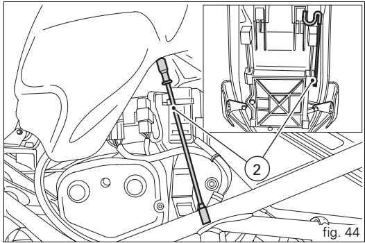
text_image
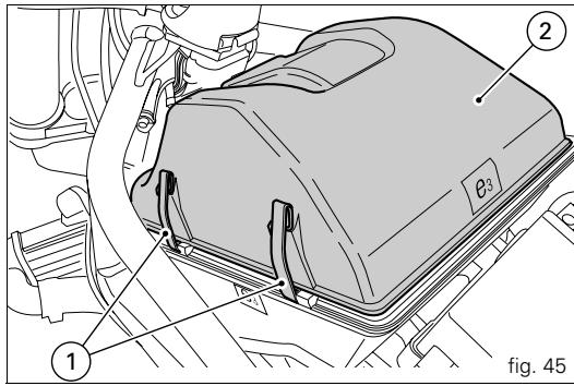
Technical diagram showing mechanical assembly with labeled parts and figure number 44Changing the air filter (fig. 45)
The air filter must be changed at the intervals indicated in the "Routine maintenance" schedule (see Warranty Card). To access the airbox, lift the fuel tank as described in (page 49).
To remove the filter, unhook the tabs (1) securing the cover on both sides of the airbox and remove the cover (2).
Remove the old filter cartridge (3, fig. 46) and fit a new one.

Important
A dirty filter reduces the amount of intake air, which increases fuel consumption, reduces engine power and causes deposits to form on the spark plugs.
Do not use the motorcycle without a filter; as impurities in the air could get into the engine and cause damage.
Reinstall the filter correctly in its housing in the airbox, as shown in the figure, and refit all the parts originally removed.

Important
If the vehicle is used in very damp or dusty conditions the air filter cartridge must be changed more frequently than indicated in the routine maintenance table (Warranty Card).
text_image
1 2 θ³ fig. 45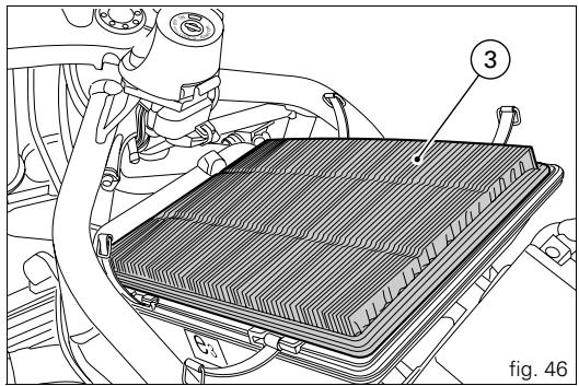
natural_image
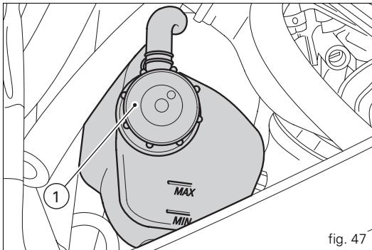
Technical diagram of a car air vent with labeled component (3), no readable text or symbols beyond labelsChecking coolant level (fig. 47)
Check the coolant level in the expansion tank on the right-hand side of the motorcycle; it must be between the MAX and MIN marks on the tank.
If the level is low, top it up.
Unscrew the filler cap (1) and add a mixture consisting of water and antifreeze SHELL Advance Coolant or Glycoshell (35-40% of the volume) up to MAX mark.
Replace the cap (1).
This type of mixture gives the best operating conditions (the coolant starts to freeze at -20 ^/-4 ^ ).
Cooling circuit capacity: 2,7 dm ^3 (litres).

Warning
This operation must be carried out with the engine cold and with the motorcycle perfectly level.
text_image
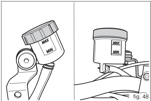
MAX MIN 1 fig. 47Checking the brake and clutch fluid levels
(fig. 48)
The levels should not fall below the MIN marks on the respective reservoirs.
If the level is too low it can allow air to get into the circuit, thus impairing the efficiency of the relative system.
Brake and clutch fluid must be topped up and changed at the intervals specified in the routine maintenance schedule see Warranty Card) by a Ducati Dealer or Authorized Workshop.

Important
It is recommended that all brake and clutch hoses
be renewed every 4 years.
Brake system
If there is excessive play at the brake lever or pedal even though the brake pads are still in good condition, contact a Ducati Dealer or Authorized Workshop to have the system inspected and any air expelled from the circuit.

Warning
Brake and clutch fluid is harmful to paintwork and plastic
parts, so do not allow it to come into contact with them.
Hydraulic oil is corrosive and can cause damage and injuries.
Never mix different quality oils.
Check that the seals are in good condition.
text_image
MAX MIN MAX MIN fig. 48Clutch system
If there is too much play at the control lever and the motorcycle jumps or stops when a gear is engaged, this indicates air in the system. Contact a Ducati Dealer or Authorized Service Centre to have the system inspected and the air bled from the system.

Warning
The level of clutch fluid tends to increase in the reservoir as the friction material on the clutch plates wears out. Do not exceed the specified level (3 mm above the minimum level).
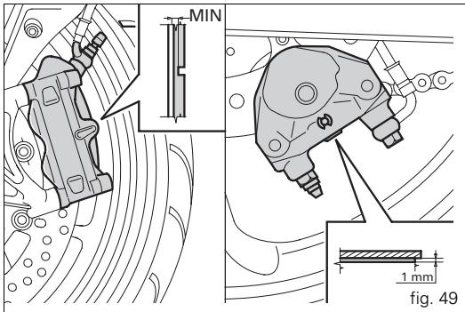
Checking the brake pads for wear (fig. 49)
Front brake
The brake pads are marked with wear indicators so that they can be checked without removing them from the calipers. If the grooves in the pad friction material are still visible, the pad is still in good condition.
Rear brake
The thickness of the friction material on each pad must be at least 1 mm.

Important
Have the brake pads replaced at a Ducati Dealer or
Authorized Service Centre.
Adjusting the throttle cable
In all steering positions, the throttle twistgrip should have about 2 – 4 mm of free travel, measured at the outer edge of the twistgrip housing. If necessary, adjust the play with the adjuster (1, fig. 50) located on the twistgrip itself.
text_image
MIN 1 mm fig. 49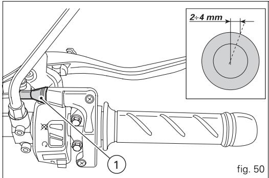
text_image
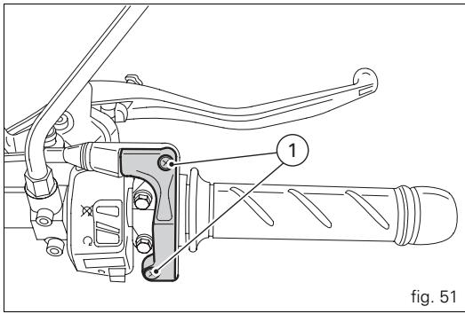
2÷4 mm 1 fig. 50Lubricating cables and joints (fig. 51)
The condition of the throttle cable sheaths should be checked at regular intervals. There should be no signs of pinching or cracking on the outer plastic sheath. Operate the control to check that the inner cable slides smoothly: if you feel any rubbing or catching, have the cable replaced by a Ducati Dealer or Authorized Service Centre.
To prevent problems, periodically lubricate the ends of each control cable with SHELL Advance Grease or Retinax LX2.
In the case of the throttle cable, open the twistgrip housing by unscrewing the two screws (1) and grease the end of the cable and the race.

Warning
Close the twistgrip housing carefully, inserting the in the race.
Refit the housing and tighten the screws (1) to 1.8 Nm.
To ensure smooth operation of the pivot on the sidestand, remove any dirt and apply SHELL Alvania R3 to all points subject to friction.
text_image
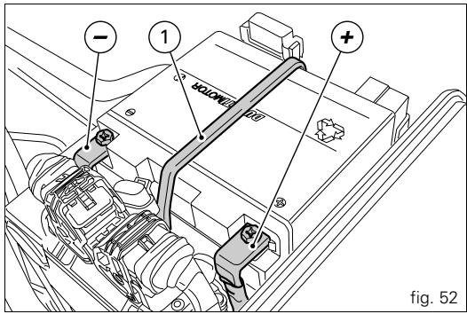
fig. 51Charging the battery (fig. 52)
Before charging the battery, it is best to remove it from the motorcycle.
First disconnect the black negative terminal (-), then the red positive terminal (+).
Release the retaining clamp (1) and remove the battery.

Warning
The battery produces explosive gases: keep it away from heat sources and flames.
Charge the battery in a well-ventilated area.
Connect the battery charger leads to the battery terminals: red to the positive terminal (+), black to the negative terminal (-).

Important
Connect the battery to the charger before switching on to prevent sparks at the battery terminals that could ignite the gases inside the cells.
Always connect the red positive terminal first.

Warning
Keep the battery out of the reach of children.
Charge the battery at 1 A for 5 to 10 hours.
text_image
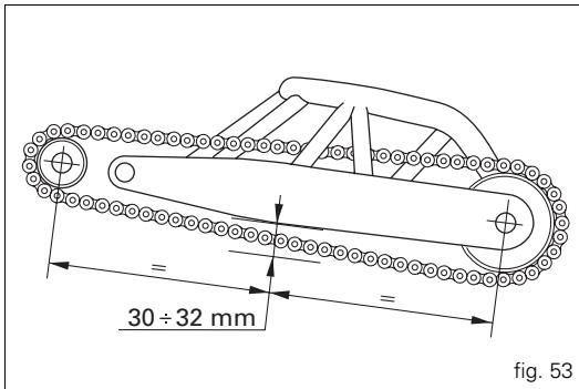
- 1 SOMEN + fig. 52Checking the chain tension (fig. 53)
Move the motorcycle slowly until you find the point at which the upper section of the chain is most taut. Place the motorcycle on its sidestand. Push the chain upwards with a finger in correspondence with the centre of the swingarm (see adhesive label). The bottom run of the chain must be able to deflect 30 to 32 mm. If not, have the chain tensioned at a Ducati Dealer or Authorized Workshop.

Warning
For the safety of the rider, it is essential that the tric hub clamp bolts are correctly tightened.

Important
An incorrectly tensioned chain will cause the rapid wear of transmission parts.
Lubrication of the drive chain
The chain fitted on your motorcycle has O-rings to protect its moving parts from dirt, and to hold the lubricant inside. So as not to damage these seals when cleaning the chain, use special solvents and avoid aggressive washing with high-pressure steam cleaners. After cleaning, blow the chain dry with compressed air or wipe with an absorbent material, then lubricate each link with SHELL Advance Chain or Advance Teflon Chain.
text_image
30 ÷ 32 mm fig. 53
Important
Using non-specific lubricants may cause severe damage to the chain and the front and rear sprockets.
Replacing bulbs
Before replacing a burnt-out bulb, make sure that the new one complies with voltage and wattage as specified in the "Electrical System" for that lighting device at page 78.
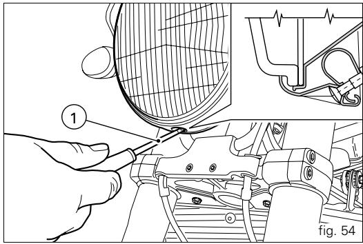
Headlight (fig. 54)
To facilitate access to the headlight for servicing, remove the headlight shell as explained in “Removing the headlight shell” (page 48).
To access the headlight bulbs, unscrew the lower screw (1) securing the lens/reflector assembly to the headlight body. Disconnect the wiring connector (2, fig. 55) from the headlight bulb. Release the bulb retaining clip (3, fig. 55) and remove the bulb from its housing.
text_image
① fig. 54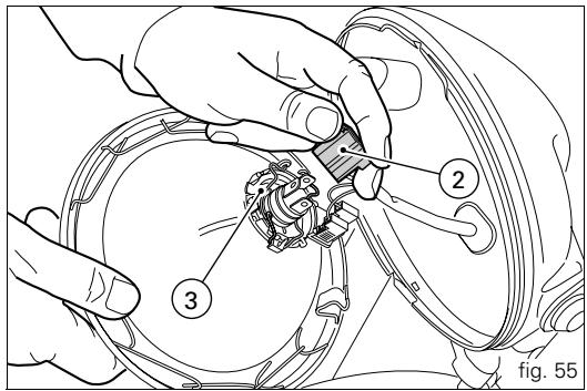
text_image
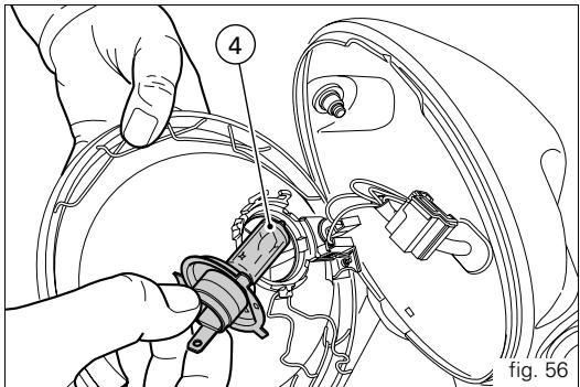
2 3 fig. 55Fit a new bulb (4, fig. 56).

Notes
Do not touch the transparent part of the bulb with your fingers, this will darken it and cause a loss of brightness. Insert the tabs on the bulb base into the corresponding slots in the bulb housing to ensure the bulb is correctly positioned; hook the end of the clip (3, fig. 55) on to the headlight mountings. Reconnect the wiring.
To replace the parking light bulb, detach its wiring connector. The bulb (5, fig. 57) is of the bayonet type: push it in and turn it anti-clockwise to remove it. Push the new bulb in and turn it clockwise until it clicks into place. Reconnect the wiring connector and replace the lens/reflector assembly.
text_image
4 fig. 56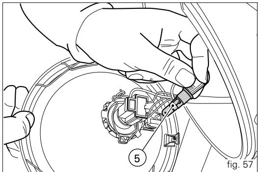
natural_image
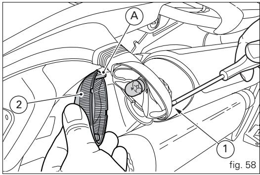
Technical illustration of hands connecting a mechanical component to a circular housing (no text or symbols)Turn signals (fig. 58)
Loosen the screw (1) and detach the lens (2) from the turn signal light.
The bulb has a bayonet-type base: to remove it, push it in and turn it counter-clockwise. Push in the new bulb and turn it clockwise until it clicks into place. Refit the lens by inserting the tab (A) in the corresponding slot in the turn signal. Refit and tighten the screw (1).
Brake light (fig. 59)
To change the brake light bulb, loosen the two screws (1) securing the lens (2) and remove it. The bulb has a bayonet-type base: to remove it, push it in and turn it counterclockwise. Push in the new bulb and turn it clockwise until it clicks into place. Refit the lens.
text_image
A 2 0 1 fig. 58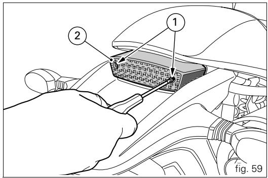
text_image
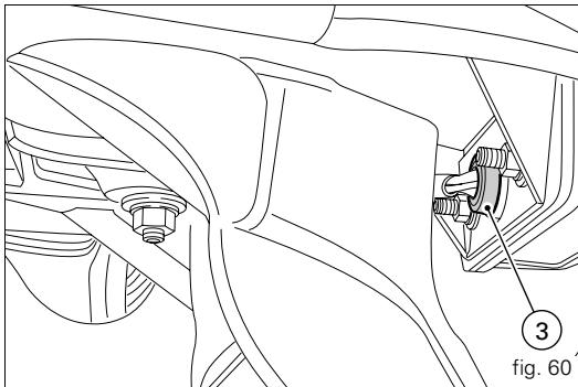
Technical diagram showing a hand inserting a component into a car's internal panel, labeled with parts 1 and 2.Number plate light (fig. 60)
To access the bulb in the number plate light (3), pull the bulb holder out from the light, then pull the bulb out of the holder and renew it.
natural_image
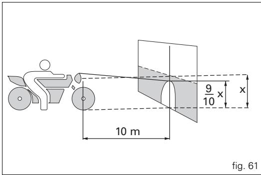
Technical line drawing of a mechanical assembly with no visible text or symbolsHeadlight aim (fig. 61)
To check the headlight aim, place the motorcycle upright with the tyres inflated to the correct pressure and one person sitting astride the motorcycle. The motorcycle should be perfectly vertical, with its longitudinal axis at right angles to a wall or screen at a distance of 10 metres. Draw a horizontal line on the wall at the height of the centre of the headlight and a vertical one in line with the longitudinal axis of the motorcycle.
If possible, perform this check in conditions of low ambient light.
Switch on the low beam headlight.
The height of the upper limit between the dark area and the lit area must not be more than nine tenths of the height of the centre of the headlamp from the ground.

Notes
Note: this procedure is the one specified by Italian regulations for checking the maximum height of light beams. Owners in other countries should adapt this procedure to the regulations in force in the country where the motorcycle is used.
The vertical aim of the headlamp is adjusted by turning the screws (1, fig. 62) that attach it to the side mountings.
text_image
9/10 x x 10 m fig. 61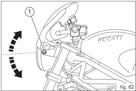
text_image
1 PUCATT fig. 62Tyres
Front tyre pressure:
2,1 bar -2.3 kg/cm ^4
Rear tyre pressure:
2,2 bar -2.4 kg/cm²
E
As tyre pressures are affected by changes in temperature and altitude, check and adjust them whenever you are riding in areas where there are large variations in temperature or altitude.

Important
Check and adjust the pressures with the tyres cold.
To prevent distortion of the front wheel rim, increase tyre pressure by 0.2 to 0.3 bar when riding on bumpy roads.
Repairing or renewing tyres
With minor punctures, tubeless tyres take a long time to deflate, as they tend to hold the air inside. If you find that one of the tyres is slightly deflated, check the tyre for slow punctures.

Warning
Punctured tyres must be renewed.
Replace with tyres of the original brand and type. Be sure to tighten the valve dust caps securely to prevent leaks while riding. Never fit tyres with inner tubes, as these can cause the tyre to burst suddenly, with possibly serious consequences for the rider and passenger.
After renewing a tyre, the wheel must be balanced.

Important
Do not remove or alter the position of the wheel balancing weights.

Notes
If tyres need changing, contact a Ducati Dealer or Authorized Service Centre to make sure wheels are removed and refitted correctly.
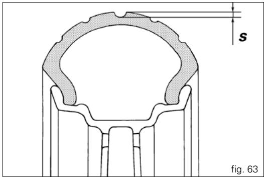
Minimum tread depth
Measure the tread depth (S, fig. 63) at the point where the tread is most worn.
It should not be less than 2 mm, and in any case not less than the legal limit.

Important
Visually inspect the tyres at regular intervals for cracks and cuts, especially on the side walls, and bulges or large stains that indicate internal damage. Replace them if badly damaged.
Remove any stones or other foreign bodies stuck in the tread.
text_image
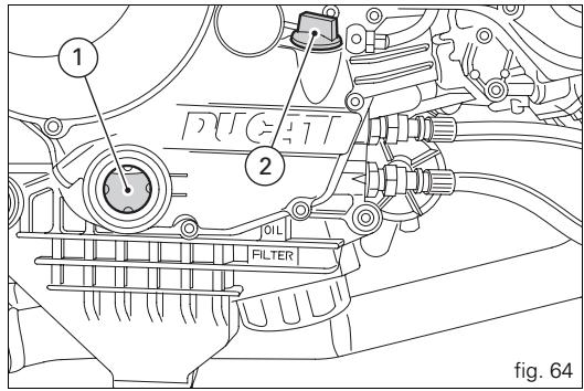
s fig. 63Checking the engine oil level (fig. 64)
Check the engine oil level through the sight glass (1) on the right-hand crankcase cover.
When checking oil level, the motorcycle should be upright and the engine cold.
The oil level should be between the marks next to the sight glass. Top up oil level with SHELL Advance Ultra 4, if low.
Undo the filler cap (2) and top up to correct level. Replace the filler cap.

Important
Engine oil and oil filters must be changed by a
Ducati Dealer or Authorized Workshop at regular intervals, as specified in the routine maintenance schedule (see Warranty Card).
Oil viscosity
SAE 10W-40
The other viscosity values shown in the table can be used if the local average temperature is within the limits specified for that oil viscosity.
text_image
1 2 OIL FILTER fig. 64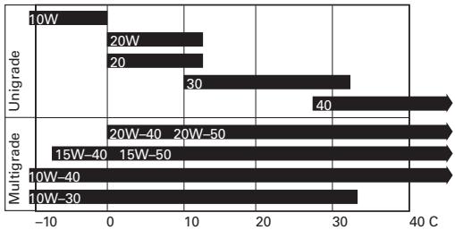
bar
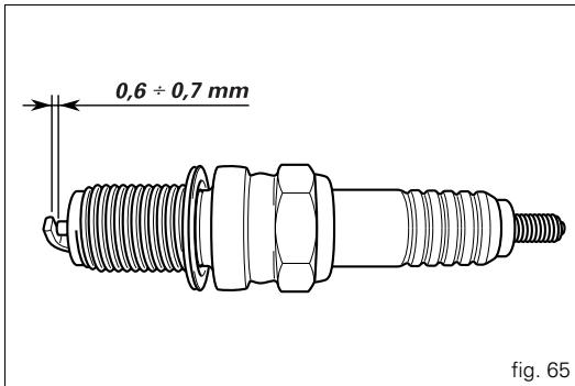
| Condition | Temperature (°C) | Value | |---|---|---| | Unigrade | 10W | -2 | | Unigrade | 20W | 11 | | Unigrade | 20 | 11 | | Unigrade | 30 | 31 | | Multigrade | 15W-40 | -8 | | Multigrade | 15W-50 | -8 | | Multigrade | 20W-40 | -6 | | Multigrade | 20W-50 | -6 | | Multigrade | 40W | 27 | | Multigrade | 10W-40 | -6 | | Multigrade | 10W-30 | -6 | | Multigrade | 10W-30 | -6 |Cleaning and renewing the spark plugs (fig. 65)
Spark plugs are an important part of the engine and should be checked at regular intervals.
This is a relatively simple operation and provides a good indication of how well the engine is running.
Disconnect the HT leads from the spark plugs and remove them from the cylinder heads with the wrench provided.
Check the colour of the ceramic insulation around the central electrode: an even brown colour is a sign that the engine is in good condition.
If the insulation is any other colour, or if there are dark deposits, renew the spark plug and describe the condition of the old plug to a Ducati dealer or Authorized Service Centre. Also check the central electrode; if it is worn or glazed, renew the spark plug.
Check the electrode gap, which must be: 0,6 ÷ 0,7 mm.

Important
Take care when bending the side electrode to adjust the gap. A gap outside the specified limits will adversely affect engine performance and may lead to difficult starting or erratic idling.
Thoroughly clean the electrode and insulation using a wire brush, and check the condition of the washer.
Clean the spark plug socket on the head and take care not to allow foreign bodies to fall into the combustion chamber.
text_image
0,6 ÷ 0,7 mm fig. 65Insert the spark plug in the cylinder head and screw in fully by hand. Tighten to a torque of 20 Nm.
If you do not have a torque wrench, after tightening by hand, turn the unit a further half turn with the provided wrench.

Important
Do not use spark plugs with an unsuitable heat rating or incorrect reach.
The spark plug must be tightened correctly.
General cleaning
To preserve the original shine on metal surfaces and paintwork, wash and clean your motorcycle at regular intervals depending on the type of use and according to the particular road conditions. Use specific products, where possible biodegradable. Avoid aggressive detergents or solvents.
E

Important
Do not wash your motorcycle immediately after use, as marks can form due to evaporation of the water on hot surfaces.
Never clean the motorcycle using hot or high-pressure water jets. Cleaning the motorcycle with high-pressure washers may lead to seizure or severe failure of the front forks, wheel axles, electrical system, front fork seals, air inlets or exhaust silencers and adversely affect the operation of motorcycle safety features.
If parts of the engine are unusually dirty or greasy, use a degreasing agent, avoiding contact with transmission components (chain, front and rear sprockets, etc.). Rinse with warm water and dry all surfaces with chamois leather.

Warning
There may be loss of braking efficiency immediately after washing the motorcycle. Never grease or lubricate the brake discs. This will cause loss of braking efficiency. Clean the discs with an oil-free solvent.
Storing the motorcycle
If the motorcycle is to be left unused for a long period, it is advisable to carry out the following operations first:
clean the motorcycle;
drain the fuel from fuel tank;
pour a few drops of engine oil into the cylinders through the spark plug bores, then crank the engine by hand a few times to form a protective film of oil on the cylinder inner walls; support the motorcycle on the sidestand; disconnect and remove the battery. If the motorcycle has been left unused for more than a month, the battery should be checked and re-charged if necessary.
Protect the motorcycle with a special motorcycle cover that will not damage the paintwork or retain moisture.
This type of motorcycle cover is available from Ducati Performance.
Important notes
The legislation in some countries (France, Germany, Great Britain, Switzerland etc.) sets certain noise and pollution standards.
Periodically carry out the required checks and renew parts as necessary, using Ducati original spare parts, in compliance with the regulations in the country concerned.
Maintenance
E
Programmed maintenance plan: operations to be carried out by the dealer
* Service operation to be carried out in accordance with the specified distance or time intervals (km, miles or months), whichever occurs first.
| List of operations with type of intervention (distance or time interval *) | km x1000miles x1000Months | 1 | 12 | 24 | 36 | 48 | 60 |
| 0,6 | 7,5 | 15 | 22,5 | 30 | 37,5 | ||
| 6 | 12 | 24 | 36 | 48 | 60 | ||
| Change the engine oil | ● | ● | ● | ● | ● | ● | |
| Change the engine oil filter | ● | ● | ● | ● | ● | ● | |
| Clean the engine oil pick-up filter | ● | ||||||
| Check the engine oil pressure | ● | ● | |||||
| Check and/or adjust the valve clearances (1) | ● | ● | ● | ● | ● | ||
| Check the tension of the timing belts (1) | ● | ● | ● | ||||
| Renew the timing belts | ● | ● | |||||
| Check and clean the spark plugs. Renew if necessary | ● | ● | |||||
| Check and clean the air filter (1) | ● | ● | ● | ||||
| Change the air filter | ● | ● | |||||
| Check throttle body synchronisation and idle speed setting (1) | ● | ● | ● | ● | ● | ||
| Check the brake and clutch fluid levels | ● | ● | ● | ● | ● | ● | |
| Change the clutch and brake fluid | ● | ||||||
| Check and adjust the brake and clutch control cables | ● | ● | ● | ● | ● | ||
| Check/lubricate the throttle/cold start cable | ● | ● | ● | ● | ● | ||
| Check tyre pressure and wear | ● | ● | ● | ● | ● | ● | |
| Check the brake pads. Renew if necessary | ● | ● | ● | ● | ● | ● | |
| Check the steering head bearings | ● | ● | |||||
| Check the drive chain tension, alignment and lubrication | ● | ● | ● | ● | ● | ● | |
| Check the clutch disc pack. Renew if necessary (1) | ● | ● | ● | ● | ● | ||
| Check coolant level | ● | ● | ● | ● | ● | ||
| Change the coolant | ● | ||||||
| Check operation of electric fans and sealing of coolant circuit | ● | ● | ● | ● | ● | ||
| Check the rear wheel cush drive | ● | ● | |||||
| Check the wheel hub bearings | ● | ● | |||||
| Check the indicators and lighting | ● | ● | ● | ● | ● | ||
| Check tightness of nuts and bolts securing the engine to the frame | ● | ● | ● | ● | ● | ||
| Check the sidestand | ● | ● | ● | ● | ● | ||
| Check tightness of the front wheel axle nut | ● | ● | ● | ● | ● | ||
| Check tightness of the rear wheel axle nut | ● | ● | ● | ● | ● | ||
| Check the external fuel hoses | ● | ● | ● | ● | ● | ||
| Change the front fork oil | ● | ||||||
| Check the forks and rear shock absorber for oil leaks | ● | ● | ● | ● | ● | ||
| Check the front sprocket retaining bolts | ● | ● | ● | ● | ● | ||
| General lubrication and greasing | ● | ● | ● | ● | ● | ||
| Check and recharge the battery | ● | ● | ● | ● | ● | ||
| Road test the motorcycle | ● | ● | ● | ● | ● | ● | |
| General cleaning | ● | ● | ● | ● | ● |
(1) Operation to be carried out only at the specified distance intervals
Programmed maintenance plan: operations to be carried out by the dealer
| List of operations with type of intervention (distance or time interval *) | km x1000 | 1 |
| miles x1000 | 0,6 | |
| Months | 6 | |
| Check the engine oil level | ● | |
| Check the brake and clutch fluid levels | ● | |
| Check tyre pressure and wear | ● | |
| Check the drive chain tension and lubrication | ● | |
| Check the brake pads. If necessary, contact your dealer to renew pads | ● | |
* Service operation to be carried out in accordance with the specified distance or time intervals (km, miles or months), whichever occurs first.
Technical data
E
Overall dimensions (mm) (fig. 66)
Weights
Weights
Dry weight:
177 kg.
Fully laden:
390 kg.

Warning
Failure to observe weight limits could result in poor handling and impair the performance of your motorcycle, and could result in loss of control.

text_image
RUGGTT 128 355 1440 2121 806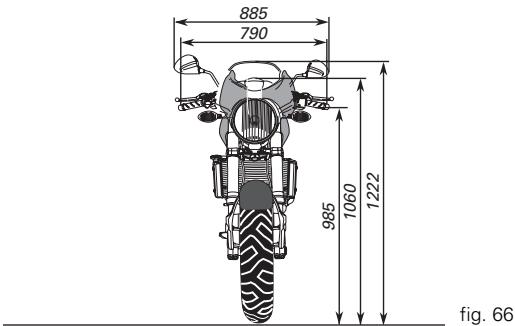
text_image
885 790 985 1060 1222 fig. 66| Fuel, lubricants and other fluids | Type | dm3(litres) |
| Fuel tank, including a reserve of 3.5 dm3(litres) | Unleaded fuel with at least 95 octane rating | 15 |
| Lubrication circuit | SHELL Advance Ultra 4 | 3,4 |
| Front/rear brake and clutch circuits | SHELL Advance Brake DOT 4 | — |
| Protection for electrical contacts | SHELL Advance Contact Cleaner | — |
| Front fork | SHELL Advance Fork 7.5 or Donax TA | 0.443 (each leg) MS4R0.492 (each leg) MS4RS |
| Cooling system | Antifreeze SHELL Advance Coolant or 35-40% + water | 2,7 |

Important
Do not use additives in fuel or lubricants.
Engine
Longitudinal 90° "L" twin cylinder, four-stroke.
Bore (mm):
100.
Stroke (mm):
63,5.
Total displacement cm ^3 :
998.
Compression ratio:
11,4±0,5:1.
Max power at crankshaft (95/1/EC):
88.8 kW - 119 HP at 9,250 rpm.
Max torque at crankshaft (95/1/EC):
96,9 Nm (9.9 kgm) at 7,500 rpm.
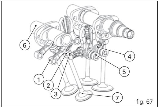
Timing system
Desmodromic (type) with four valves per cylinder, operated by eight rocker arms (4 opening rockers and 4 closing rockers) and two overhead camshafts.
Driven by the crankshaft through spur gears, timing belt pulleys and toothed timing belts.
Desmodromic timing system (fig. 67)
1) Opening (or upper) rocker arm;
2) opening shim;
3) closing (or lower) shim;
4) return spring for closing rocker;
5) closing (or lower) rocker arm;
6) camshaft;
7) valve.
text_image
6 1 2 3 4 5 7 fig. 67Performance data
Maximum speed in any gear should be reached only after the correct running-in period with the motorcycle properly serviced at the recommended intervals.

Important
Failure to follow these instructions will release
Ducati Motor Holding S.p.A. from any liability for any engine damage or shortened engine life.
Spark plugs
Make: CHAMPION
Type: RG 4 HC
Fuel system
Indirect electronic injection (MARELLI)
Throttle body diameter:
50 mm
Injectors per cylinder: 1
Holes per injector: 1
Fuel supply: 95-98 RON.
Brakes
Front
Type:
with drilled steel disc.
2 discs.
Braking surface material: steel.
Flange material:
aluminium.
Disc diameter: 320 mm.
Hydraulically operated by a control lever on right handlebar.
Braking surface, cm ^2 : 52.52.
Radially mounted brake calipers.
Make and type: BREMBO P4.34B.
Friction material: Toshiba TT2172.
Master cylinder type: PR18/19.
Rear
Type:
with fixed drilled steel disc.
Disc diameter: 245 mm.
Hydraulically operated by pedal on R.H. side.
Braking surface: 25 cm ^4 .
Brake caliper: 32 mm ∅ piston.
Make and type: BREMBO P32F.
Friction material: FERIT I/D 450 FF.
Master cylinder type: PS 11B.

Warning
The brake fluid used in the brake system is corrosive.
In the event of accidental contact with eyes or skin, wash the affected area with copious amounts of running water.
Transmission
Clutch:
dry multiplate;
operated by control lever on left handlebar.
Transmission from engine to gearbox main shaft via spur gears.
Ratio:
32/59.
Gearbox:
6 -speed;
with constant mesh gears, gearchange pedal on left.
Front sprocket/clutch sprocket ratio:
15/43.
Total gear ratios:
1^st 15/37
2^nd 17/30
3^rd 20/27
4^th 22/24
5^th 24/23
6^th 28/24
Drive chain from gearbox to rear wheel:
Make: DID
Type: 525 HV
Dimensions: 5/8" x 5/16"
No. of links: 106.

Important
The above gear ratios are approved and should not be modified under any circumstances.
However, if you wish to tune up your motorcycle for competitions or special tracks, Ducati Motor Holding S.p.A. will be pleased to provide information about the special ratios available. Please contact a Ducati Dealer or Authorized Service Centre.

Warning
To replace the rear sprocket, contact a Ducati Dealer or Authorized Service Centre.
Incorrect replacement of this component could seriously endanger rider and passenger safety and cause irreparable damage to the motorcycle.
Frame
High-strength tubular steel trellis.
Steering angle (on each side): 27°
Trail mm: 96
Steering head rake: 24°.
Wheels
Five Y-spokes, light-alloy rims.
Front
Dimensions: MT3.50x17".
Rear
Dimensions: MT5.50x17".
Both wheels have removable axles.
Tyres
Front
Radial tubeless tyre
Size: 120/70-ZR17
Rear
Radial tubeless tyre
Size: 180/55-ZR17
Suspension
Front
Upside-down hydraulic forks.
The fork is provided with outer adjuster for rebound, compression, and preload (for inner springs of fork legs).
Stanchion diameter mm:
43.
Travel along leg axis.
130 mm.
Rear
Progressive linkage with a rocker arm connecting the frame and upper pivot point of the shock absorber. The shock absorber can be adjusted for rebound damping, compression damping and spring preload Pivots at the lower end on the aluminium swingarm.
The swingarm pivots on a shaft which passes through the engine. This system gives the motorcycle excellent stability.
Shock absorber travel:
65 mm.
Rear wheel travel:
148 mm.

Notes
Do not carry out any operations on the motorcycle that could modify the technical characteristics for which approval was obtained.
Exhaust system
Equipped with catalytic converter in compliance with Euro 3 emission regulations.
USA model: not catalyzed.
Available colours
MS4R
Ducati anniversary red, code F_473.101 (PPG) (excluding
California, Canada);
Transparent, code 228.880 (PPG)
with white stripe
Red frame with black wheels.
Titanium code 928D184 (PALINAL) (California and Canada only);
Transparent, code 923i0652 (PALINAL)
with black stripe;
Red frame with black wheels.
MS4RS
Ducati anniversary red code F_473.101 (PPG);
Transparent, code 228.880 (PPG)
with white stripe
Red frame with black wheels.
Gloss black, code 248.514 (PPG);
Transparent, code 228.880 (PPG)
with grey stripe;
Black frame and wheels.
Pearl, code *0040 (PPG);
Primer, code 490.019 (PPG)
Transparent, code 228.880 (PPG)
with red stripe;
Red frame with white wheels.
Electrical system
The main components of the electrical system are:
Headlight:
bulb type: H4 (12 V-55/60 W).
Sidelight:
bulb type: T4W (12 V-4 W).
Electrical controls on handlebars:
Turn signals:
bulb type: R10W (12 V-10 W).
Horn.
Brake light switches.
Battery, 12 V-10 Ah.
Alternator 12 V-520 W.
Electronic voltage regulator (rectifier), protected by a 30 A fuse near the battery.
Starter motor, 12 V-0.7 kW.
Tail light and brake light:
bulb type: P21/5W (12 V-5/21 W).
Number plate light:
bulb type: W5W (12 V-5 W).

Notes
To replace the bulbs, refer to the paragraph
"Changing the bulbs" on page 57.
Fuses
The fuse box is located under the fuel tank.
To access the fuses, remove the cover (1, fig. 68), which shows the positions and amp ratings of the fuses.
The fuse located nearest to the battery protects the electronic regulator.
Remove the protective cap (2, fig. 68) to access the fuse.
A blown fuse can be identified by a broken filament (3, fig. 69).

Important
To avoid possible short circuits, switch the ignition key to OFF before renewing the fuse.

Warning
Never use a fuse with a rating other than that specified.
Failure to observe this rule may damage the electric system or even cause fire.
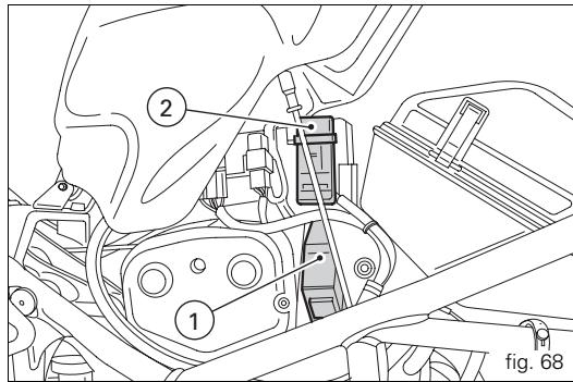
text_image
② ① fig. 68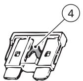
natural_image
Technical line drawing of a mechanical component with no visible text or symbolsIN GOOD CONDITION
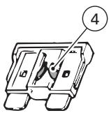
text_image
④BLOWN
fig. 69
Key to the electrical system / injection system diagram
1) Right-hand handlebar switch
2) Transponder antenna
3) Key switch
4) Fans relay
5) Lights relay
6) Fusebox
7) LH fan
8) RH fan
9) Starter motor
10) Starter contactor
11) "Antibounce" diode
12) Battery
13) Master fuse
14) Regulator
15) Alternator
16) Rear right turn signal
17) Tail light
18) Number plate light
19) LH rear turn indicator
20) Fuel tank
21) Injection relay
22) Self-diagnosis connection
23) Speed sensor
26) Horizontal cylinder coil
27) Vertical cylinder coil
28) Horizontal cylinder spark plug
29) Vertical cylinder spark plug
30) Horizontal cylinder injector
31) Vertical cylinder injector
32) Throttle position sensor
33) Rpm/timing sensor
34) Coolant temperature sensor (ECU)
35) Stepper motor
The electrical system wiring diagram is at the end of
this manual.
Routine servicing record
| km | Name of Ducati Service | Mileage | Date |
| 1000 | |||
| 12000 | |||
| 24000 | |||
| 36000 | |||
| 48000 | |||
| 60000 |
For United States of America version Only
Reporting of safety defects
If you believe that your vehicle has a defect which could cause a crash or could cause injury or death, you should immediately inform the National Highway Traffic Safety Administration (NHTSA) in addition to notifying Ducati North America. If NHTSA receives similar complaints, it may open an investigation, and if it finds that a safety defect exists in a group of vehicles, it may order a recall and remedy campaign. However, NHTSA cannot become involved in individual problems between you, your dealer, or Ducati North America. To contact NHTSA, you may either call the Auto Safety Hotline toll-free at 1-800-424-9393 (or 366-0123 in Washington, D.C. area) or write to: NHTSA, U.S. Department of Transportation, Washington, D.C. 20590. You can also obtain other information about motor vehicle safety from the Hotline.
Safety warnings
Traffic Rules vary from jurisdiction to jurisdiction. Know the regulations in your jurisdiction before riding this motorcycle.

Warning
This motorcycle is designed and intended for use on streets and other smooth, paved areas only. Do not use this motorcycle on unpaved surfaces. Such use could lead to upset or other accident.
Noise emission warranty
Ducati Motor S.p.A. warrants that this exhaust system, at the time of sale, meets all applicable U.S. EPA Federal noise standards. This warranty extends to the first person who buys this exhaust system for purposes other than resale, and to all subsequent buyers. Warranty claims should be directed to: Ducati North America, Inc., 10443 Bandley Drive, Cupertino, California, 95014 Tel: 001.408.253.0499 - Fax: 001.408.253.4099
Noise and exhaust emission control system information
Source of Emissions
The combustion process produces carbon monoxide and hydrocarbons. Control of hydrocarbons is very important because under certain conditions, they react to form photochemical smog when subjected to sunlight.
Carbon monoxide does not react in the same way, but is toxic. Ducati utilizes lean carburetor settings and other systems to reduce carbon monoxide and hydrocarbons.
Exhaust Emission Control System
The Exhaust Emission Control System is composed of lean carburetor settings, and no adjustments should be made except idle speed adjustments with the throttle stop screw. The Exhaust Emission Control System is separate from the crankcase emission control system.
Crankcase Emission Control System
The engine is equipped with a closed crankcase system to prevent discharging crankcase emissions into the atmosphere. Blow-by gas is returned to the combustion chamber through the air cleaner and the throttle body. Evaporative Emission Control System California motorcycles are equipped with an evaporative emission control system which consists of a charcoal canister and associated piping. This system prevents the escape of fuel vapors from the throttle body and fuel tank.
Tampering warning
Tampering with Noise Control System Prohibited. Federal Law prohibits the following acts or causing thereof:
(1) the removal or rendering inoperative by any person, other than for purposes of maintenance, repair, or replacement, of any device or element of design incorporated into any new vehicle for the purpose of noise control prior to its sale or delivery to the ultimate purchaser or while it is in use; or
(2) the use of the vehicle after such device or element of design has been removed or rendered inoperative by any person.
Among those acts presumed to constitute tampering are the acts listed below:
(1) Removal of, or puncturing the muffler, baffles, header pipes or any other component which conducts exhaust gases.
(2) Removal or puncturing of any part of the intake system.
(3) Lack of proper maintenance.
(4) Replacing any moving part of the vehicle, or parts of the exhaust or intake system, with parts other than those specified by the manufacturer.
This product should be checked for repair or replacement if the motorcycle noise has increased significantly through use. Otherwise, the owner may become subject to penalties under state and local ordinances.
Problems that may affect motorcycle emissions
If you are aware of any of the following symptoms, have the vehicle inspected and repaired by your local Ducati dealer.
Symptoms:
Hard starting or stalling after starting.
Rough idle.
Misfiring or backfiring during acceleration.
After-burning (backfiring).
Poor performance (driveability) and poor economy.
Riding safety
The points given below are applicable for every day motorcycle use and should be carefully observed for safe and effective vehicle operation.
A motorcycle does not provide the impact protection of an automobile, so defensive riding in addition to wearing protective apparel is extremely important.
Do not let protective apparel give you a false sense of security. Before changing lanes, look over your shoulder to make sure the way is clear. Do not rely solely on the rear view mirror; you may misjudge a vehicle's distance and speed, or you may not see it at all.
When going up steep slopes, shift to a lower gear so that there is plenty of power to spare rather than overloading the engine.
When applying the brakes, use both the front and rear brakes. Applying only one brake for sudden braking may cause the motorcycle to skid and lose control.
When going down long slopes, control vehicle speed by closing the throttle. Use the front and rear brakes for auxiliary braking.
Riding at the proper rate of speed and avoiding unnecessarily fast acceleration are important not only for safety and low fuel consumption but also for long vehicle life and quieter operation.
When riding in wet conditions or on loose roadway surfaces, the ability to maneuver will be reduced. All of your actions should be smooth under these conditions. Sudden acceleration, braking or turning may cause loss of control. When the roadway is wet, rely more on the throttle to control vehicle speed and less on the front and rear brakes.
The throttle should also be used judiciously to avoid skidding the rear wheel from too rapid acceleration or deceleration.
On rough roads, exercise caution, slow down, and grip the fuel tank with your knees for better stability.
When quick acceleration is necessary as in passing, shift to a lower gear to obtain the necessary power.
Do not down shift at too high an r.p.m. to avoid damage to the engine from overreving.
Avoiding unnecessary weaving is important to the safety of both the rider and other motorists.
Do not exceed the legal speed limit or drive too fast for existing conditions. High speed increases the influence of any condition affecting stability and the loss of control.
Operate motorcycle only at moderate speed and out of traffic until you have become thoroughly familiar with its operation and handling characteristics under all conditions. This is a very high performance motorcycle, designed and intended for use by experienced careful riders only!
A new motorcycle must be operated according to a special break-in procedure (see Running in recommendations).

Warning
Before starting engine, check for proper operation of brake, clutch, shifter, throttle controls, correct fuel and oil supply.
Gasoline is extremely flammable and is explosive under certain conditions. Refuell in a well ventilated area with the engine stopped. Do not smoke or allow open flames or sparks when refuelling or servicing the fuel system. Always close the fuel petcock when the engine is not running to prevent flooding of the throttle body. Do not overfill fuel tank (see instructions page 45).
Motorcycle exhaust contains poisonous carbon monoxide gas. Do not inhale exhaust gases and never run the engine in a closed garage or confined area. Use only Ducati approved parts and accessories. This motorcycle was not intended to be equipped with a sidecar or to be used to tow any trailer or other vehicle. Ducati does not manufacture sidecars or trailers and cannot predict the effects of such accessories on handling or stability, but can only warn that the effects will be adverse and any damage to motorcycle components caused by the use of such accessories will not be remedied under warranty.

Warning
Do not ride the motorcycle with helmets attached to the hook; the helmets could cause an accident by distracting the operator or interfering with normal vehicle operation.
Protective apparel
Always wear a helmet. Most motorcycle accident fatalities are due to head injuries. For safety eye protection, gloves, and high top, sturdy boots should also be worn.
The exhaust system becomes very hot during operation, never touch the exhaust system. Wear clothing that fully covers your legs. Do not wear loose clothing which could catch on the control levers, footrests, wheels, or chain. Any amount of alcohol will significantly interfere with your ability to safely operate your motorcycle. Don't drink and ride.
Vehicle identification number (VIN)
Every Ducati motorcycle is identified by two identification numbers (see page 9). Figure A specifically shows the frame identification numbers.
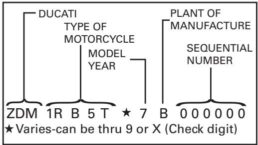
flowchart
graph TD
    A["DUCATI TYPE OF MOTORCYCLE MODEL YEAR"] --> B["ZDM 1R B 5 T ★ 7 B 0 0 0 0 0 0"]
    C["PLANT OF MANUFACTURE SEQUENTIAL NUMBER"] --> D["★ Varies-can be thru 9 or X (Check digit)"]
fig. A
Label location (fig. B)
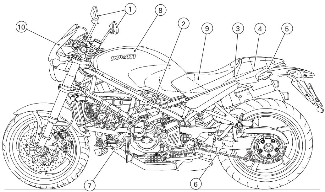
text_image
10 ① ⑧ ② ⑨ ③ ④ ⑤ DUCATI ⑦ ⑥OBJECT IN MIRROR ARE CLOSER THAN THEY APPEAR
Cnd. 633/1 108/18.
1
Manufactured by DUCATIMOTORHOLDING spa
DATE:

GVWR: Lbs (kg)
GAWR front: Lbs (kg) with tire, RIM at PSI cold.
GAWR rear: Lbs (kg) with tire, RIM at PSI cold.
This vehicle conforms to all applicable Federal Motor Vehicle Safety standards in effect on the date
of manufacture shown above. Type classification: Motorcycle
Vehicle I.D. No.:
Cnd. 633/1236/18.
2
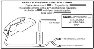
text_image
VEHICLE EMISSION CONTROL LABEL Engine displacement : cc. Engine family. This vehicle conforms to U.S. EPA and California regulations Applicable to model new motorcycles. Evap family : EVAP CANSETTER HOT AIR FILLET DOCATI: HOTCHICELING (EVI) Via A.C.Ducel3 40132 BOLOGINA ITALY TO HORIZONTAL MANFOLD TO VERTICAL MANFOLD3
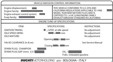
text_image
VEHICLE EMISSION CONTROL INFORMATION Engine displacement: Engine family: Engine exhaust control system: Exper family: ENGINE TUNE-UP SPECIFICATIONS ITEM SPECIFICATIONS INSTRUCTIONS IGNITION TIMING: ± bTDC at idle speed No adjustment IDLE SPEED (RPM): ± mm No adjustment IDLE MIXTURE: No adjustment Opening ± mm VALVE CLEARANCE (in & ex): Closing ± mm See Service Manual SPARK PLUG CHAMPION SPARK PLUG GAP (mm): 0.5 x OIL: 5 FUEL: Unleaded gasoline DUCATIVI/MOTORHOLDING spia - BOLOGNA - ITALY4
HELMET HOLDER UNDER THE SEAT
5
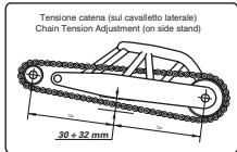
text_image
Tensione catena (sul cavalletto laterale) Chain Tension Adjustment (on side stand) 30 + 32 mm6
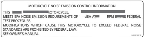
text_image
MOTORCYCLE NOISE EMISSION CONTROL INFORMATION THIS MOTORCYCLE, MEETS EPA NOISE EMISSION REQUIREMENTS OF TEST PROCEDURE. MODIFICATIONS WHICH CAUSE THIS MOTORCYCLE TO EXCEED FEDERAL NOISE STANDARDS ARE PROHIBITED BY FEDERAL LAW. SEE OWNER'S MANUAL.7
CAUTION
NEVER FILL TANK SO FUEL LEVEL RISES INTO FILLER NECK. IF TANK IS OVERFILLED, HEAT MAY CAUSE FUEL TO EXPAND AND FLOW INTO EVAPORATIVE EMISSION CONTROL SYSTEM RESULTING IN HARD STARTING AND ENGINE HESITATION.
8
ATTENTION! To avoid fuel leaks from the breather pipe, do not lift the tank when it is more than half luk.
9
WARNING
DO NOT ATTEMPT TO LOOK THROUGH THIS FAIRING. THIS IS NOT A WINDSHIELD, BUT AN AERODYNAMIC FAIRING ONLY; FAILURE TO OBSERVE THIS WARNING COULD RESULT IN A COLLISION OR UPSET AND CONSEQUENT SERIOUS BODILY INJURY.
10
California evaporation emission system (fig. C)

Important
In the event of fuel system malfunction, contact Ducati's authorized Service Centres.
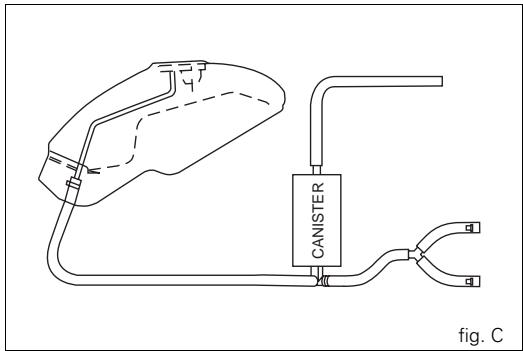
natural_image
Line drawing of a medical device with a canister and tubing, labeled 'fig. C' (no text or symbols on the diagram itself)Ducati limited warranty on emission control system
Ducati North America, Inc., 10443 Bandley Drive Cupertino, California, 95014 warrants that each new 1998 and later Ducati motorcycle, that includes as standard equipment a headlight, tail-light and stoplight, and is street legal: A) is designed, built and equipped so as to conform at the time of initial retail purchase with all applicable regulations of the United States Environmental Protection Agency, and the California Air Resources Board; and B) is free from defects in material and workmanship which cause such motorcycle to fail to conform with applicable regulations of the United States Environmental Protection Agency or the California Air Resources Board for a period of use of 30,000 kilometers (18,641 miles), or 5 (five) years from the date of initial retail delivery, whichever first occurs.
I. Coverage
Warranty defects shall be remedied during customary business hours at any authorized Ducati motorcycle dealer located within the United States of America in compliance with the Clean Air Act and applicable regulations of the United States Environmental Protection Agency and the California Air Resources Board. Any part or parts replaced under this warranty shall become the property of Ducati. In the state of California only, emissions related warranted parts are specifically defined by that state's Emissions Warranty Parts List. These warranted parts are: carburetor and internal parts; intake manifold; fuel tank, fuel injection system; spark advance mechanism; crankcase breather; air cutoff valves; fuel tank cap for evaporative emission controlled vehicles; oil filler cap; pressure control valve; fuel/vapor separator; canister; igniters; breaker governors; ignition coils; ignition wires; ignition points, condensers, and spark plugs if failure occurs prior to the first scheduled replacement, and hoses, clamps, fittings and tubing used directly in these parts. Since emission related parts may vary from model to model, certain models may not contain all of these parts and certain models may contain functionally equivalent parts.
In the state of California only, Emission Control System emergency repairs, as provided for in the California Administrative Code, may be performed by other than an authorized Ducati dealer. An emergency situation occurs when an authorized Ducati dealer is not reasonably available, a part is not available within 30 days, or a repair is not complete within 30 days. Any replacement part can be used in an emergency repair. Ducati will reimburse the owner for the expenses, including diagnosis, not to exceed Ducati's suggested retail
price for all warranted parts replaced and labor charges based on Ducati's recommended time allowance for the warranty repair and the geographically appropriate hourly labor rate. The owner may be required to keep receipts and failed parts in order to receive compensation.
II. Limitations
This Emission Control System Warranty shall not cover any of the following:
A. Repair or replacement required as a result of
(1) accident,
(2) misuse,
(3) repairs improperly performed or replacements improperly installed,
(4) use of replacement parts or accessories not conforming to Ducati specifications which adversely affect performance and/or
(5) use in competitive racing or related events.
B. Inspections, replacement of parts and other services and adjustments required for routine maintenance.
C. Any motorcycle on which odometer mileage has been changed so that actual mileage cannot be readily determined.
III. Limited liability
A. The liability of Ducati under this Emission Control Systems Warranty is limited solely to the remedying of defects in material or workmanship by an authorized Ducati motorcycle dealer at its place of business during customary business hours. This warranty does not cover inconvenience or loss of use of the motorcycle or transportation of the motorcycle to or from the Ducati dealer. Ducati shall not be liable for any other expenses, loss or damage, whether direct, incidental, consequential or exemplary arising in connection with the sale or use of or inability to use the Ducati motorcycle for any purpose. Some states do not allow the exclusion or limitation of any incidental or consequential damages, so the above limitations may not apply to you.
B. No express emission control system warranty is given by Ducati except as specifically set forth herein. Any emission control system warranty implied by law, including any warranty of merchantability or fitness for a particular purpose, is limited to the express emission control systems warranty terms stated in this warranty. The foregoing statements of warranty are exclusive and in lieu of all other remedies. Some states do not allow limitations on how long an implied warranty lasts so the above limitation may not apply to you. C. No dealer is authorized to modify this Ducati Limited Emission Control Systems Warranty.
IV. Legal rights
This warranty gives you specific legal rights, and you may also have other rights which vary from state to state.
V. This warranty is in addition to the Ducati limited motorcycle warranty.
VI. Additional information
Any replacement part that is equivalent in performance and durability may be used in the performance of any maintenance or repairs. However, Ducati is not liable for these parts. The owner is responsible for the performance of all required maintenance. Such maintenance may be performed at a service establishment or by any individual. The warranty period begins on the date the motorcycle is delivered to an ultimate purchaser.
Ducati North America, Inc.
10443 Bandley Drive
Cupertino, California, 95014
Tel: 001.408.253.0499
Fax: 001.408.253.4099
E-mail: customerservice@ducatiusa.com
Web site: www.ducatiusa.com
Routine maintenance record
| Km | mi | Ducati Service Name | Mileage | Date |
| 1,000 | 600 | |||
| 12,000 | 7,500 | |||
| 24,000 | 15,000 | |||
| 36,000 | 22,500 | |||
| 48,000 | 30,000 | |||
| 60,000 | 37,500 |
DUCATI
Ducati Motor Holding spa via Cavalieri Ducati, 3 40132 Bologna, Italia
Tel. +39 051 6413111 Fax +39 051 406580
www.ducati.com
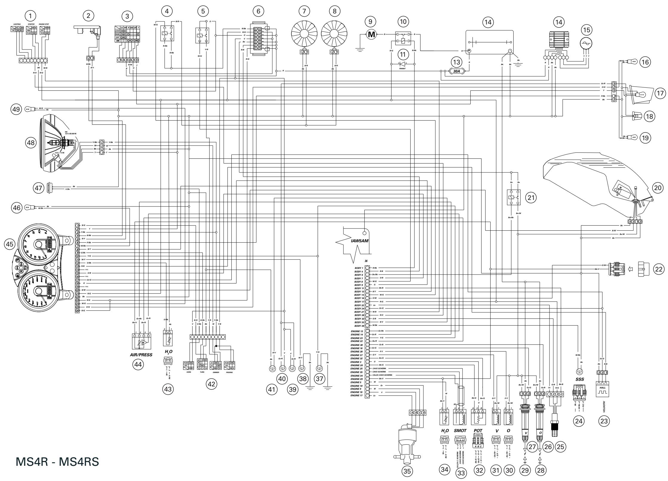
flowchart
graph TD
    subgraph MS4R - MS4RS
        A["1"] --> B["2"]
        B --> C["3"]
        C --> D["4"]
        D --> E["5"]
        E --> F["6"]
        F --> G["7"]
        G --> H["8"]
        H --> I["9"]
        I --> J["10"]
        J --> K["11"]
        K --> L["13"]
        L --> M["14"]
        M --> N["15"]
        N --> O["16"]
        O --> P["17"]
        P --> Q["18"]
        Q --> R["19"]
        R --> S["20"]
        S --> T["21"]
        T --> U["22"]
        U --> V["23"]
        V --> W["24"]
        W --> X["25"]
        X --> Y["26"]
        Y --> Z["27"]
        Z --> AA["28"]
        AA --> AB["29"]
        AB --> AC["30"]
        AC --> AD["31"]
        AD --> AE["32"]
        AE --> AF["H2O SMOT POT V O"]
        AF --> AG["H2O SMOT POT V O"]
        AH["AIR/PRESS"] --> AI["44"]
        AI --> AJ["H2O"]
        AK["AIR/PRESS"] --> AL["43"]
        AL --> AM["H2O"]
        AN["AIR/PRESS"] --> AO["42"]
        AO --> AP["H2O"]
        AQ["AIR/PRESS"] --> AR["41"]
        AR --> AS["H2O"]
        AT["AIR/PRESS"] --> AU["39"]
        AU --> AV["H2O"]
        AW["AIR/PRESS"] --> AX["37"]
        AX --> AY["H2O"]
        AZ["AIR/PRESS"] --> BA["35"]
    end
    style MS4R - MS4RS fill:#f9f,stroke:#333,stroke-width:2px
    style MS4R - MS4RS fill:#ccf,stroke:#333,stroke-width:2px