
ROG Maximus XI Gene - Motherboard ASUS - Free user manual and instructions
Find the device manual for free ROG Maximus XI Gene ASUS in PDF.


| Product Type | Motherboard |
| Brand | ASUS |
| Model | ROG Maximus XI Gene |
| Form Factor | Micro-ATX |
| Socket | LGA1151 |
| Chipset | Intel Z390 |
| Supported Processors | Intel Core 9th and 8th Gen |
| Memory Slots | 4 x DIMM |
| Maximum Memory | 64 GB |
| Memory Support | DDR4 up to 4500 MHz (OC) |
| Expansion Slots | 1 x PCIe 3.0 x16, 1 x PCIe 3.0 x4 |
| Storage Interfaces | 6 x SATA 6Gb/s, 2 x M.2 |
| Networking | Intel Gigabit LAN, Wi-Fi 5 (802.11ac) |
| Audio | SupremeFX 8-Channel HD Audio |
| USB Ports | USB 3.1 Gen 2 (rear), USB 3.1 Gen 1 (header) |
| RGB Lighting | ASUS Aura Sync compatible |
| Dimensions | 24.4 cm x 24.4 cm (9.6\" x 9.6\") |
| Weight | Approximately 1.3 kg |
| Power Connectors | 24-pin ATX, 8-pin CPU |
| Main Features | ROG overclocking utilities, BIOS FlashBack, pre-mounted I/O shield |
| Care and Cleaning | Use dry, lint-free cloth; avoid liquids |
| Safety | Anti-static precautions; handle with care |
| Spare Parts and Repairability | Standard components; CMOS battery replaceable |
| General Information | Manual available in English and Chinese |
Frequently Asked Questions - ROG Maximus XI Gene ASUS
User questions about ROG Maximus XI Gene ASUS
0 question about this device. Answer the ones you know or ask your own.
Ask a new question about this device
Download the instructions for your Motherboard in PDF format for free! Find your manual ROG Maximus XI Gene - ASUS and take your electronic device back in hand. On this page are published all the documents necessary for the use of your device. ROG Maximus XI Gene by ASUS.
USER MANUAL ROG Maximus XI Gene ASUS
Offer to Provide Source Code of Certain Software
This product contains copyrighted software that is licensed under the General Public License ("GPL"), under the Lesser General Public License Version ("LGPL") and/or other Free Open Source Software Licenses. Such software in this product is distributed without any warranty to the extent permitted by the applicable law. Copies of these licenses are included in this product.
Where the applicable license entitles you to the source code of such software and/or other additional data, you may obtain it for a period of three years after our last shipment of the product, either
(1) for free by downloading it from http://support.asus.com/download
or
(2) for the cost of reproduction and shipment, which is dependent on the preferred carrier and the location where you want to have it shipped to, by sending a request to:
ASUSTeK Computer Inc.
Legal Compliance Dept.
15 Li Te Rd.,
Beitou, Taipei 112
Taiwan
In your request please provide the name, model number and version, as stated in the About Box of the product for which you wish to obtain the corresponding source code and your contact details so that we can coordinate the terms and cost of shipment with you.
The source code will be distributed WITHOUT ANY WARRANTY and licensed under the same license as the corresponding binary/object code.
This offer is valid to anyone in receipt of this information.
ASUSTeK is eager to duly provide complete source code as required under various Free Open Source Software licenses. If however you encounter any problems in obtaining the full corresponding source code we would be much obliged if you give us a notification to the email address gpl@asus.com, stating the product and describing the problem (please DO NOT send large attachments such as source code archives, etc. to this email address).
Google™ License Terms
Copyright© 2018 Google Inc. All Rights Reserved.
Licensed under the Apache License, Version 2.0 (the "License"); you may not use this file except in compliance with the License. You may obtain a copy of the License at: http://www.apache.org/licenses/LICENSE-2.0
Unless required by applicable law or agreed to in writing, software distributed under the License is distributed on an "AS IS" BASIS, WITHOUT WARRANTIES OR CONDITIONS OF ANY KIND, either express or implied.
See the License for the specific language governing permissions and limitations under the License.
三年质保

全国联保
华硕产品质量保证卡
尊敬的华硕产品用户:
PC 机箱

Intel® LGA1151 兼容处理器风扇

Intel® LGA1151 处理器

SATA 硬盘

Phillips(十字)螺丝刀

电源供应设备

一袋螺丝

内存条

SATA 光驱(选购)

显卡(选购)

M.2 SSD 模块(选购)
- ATX power connectors (24-pin EATXPWR; 8-pin EATX12V_1-2) 1-25
- LGA1151 CPU Socket 1-4
- Fan and pump connectors (4-pin CPU_FAN; 4-pin CPU_OPT; 4-pin FS_FAN1-2; CHA_FAN; 4-pin AIO_PUMP; 4-pin W_PUMP+) 1-22
- DDR4 DIMM slots 1-5
- M.2 sockets (M.2_1; M.2_2) 1-24
- AURA RGB headers (4-pin RGB_HEADER1-2) 1-21
- DIMM.2 slot (DIMM.2_SLOT) 1-27
- MemOK! II switch (MemOK!_II_switch) 1-9
- Q_Code LED 1-16
- LN2 Mode jumper (3-pin LN2_MODE) 1-12
- Slow Mode switch (SLOW_MODE) 1-11
- Pause switch (PAUSE) 1-11
- Power-on button (START) 1-8
- RESET button (RESET) 1-8
- ReTry button (RETRY_BUTTON) 1-10
- Safe Boot button (SAFE_BOOT) 1-10
- USB 3.1 Gen 1 connector (20-1 pin U31G1_78) 1-19
- USB 3.1 Gen 2 front panel connector (U31G2_3) 1-19
- Intel ® Z390 Serial ATA 6 Gb/s connectors (7-pin SATA6G_1-4) 1-17
- Water in, water out, and water flow connectors (2-pin W_IN2; 2-pin W_OUT2; 3-pin W_FLOW2) 1-23
- System panel connectors (10-1 pin F_PANEL) 1-26
- 80 light jumper (3-pin 80_LIGHT) 1-12
- Motherboard light bar jumper (3-pin MB_LIGHT_BAR) 1-13
- USB 2.0 connectors (10-1 pin USBE34, USBE56) 1-20
- Node connector (12-1 pin NODE) 1-24
- Probelt 1-28
- Thermal sensor connector (2-pin T_SENSOR) 1-18
- Front panel audio connector (10-1 pin AAFP) 1-18
- LED connectors (8-pin LED_CON1) 1-20
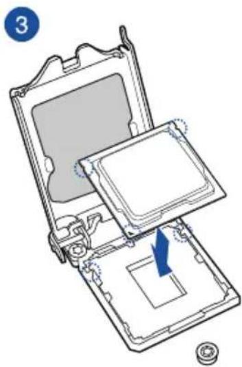
1.1.3 中央处理器(CPU)
ROG MAXIMUS XI GENE CPU LGA1151

内存建议设置

内存设置
ROG MAXIMUS XI GENE Safe Boot button

3. 硬盘指示灯(HD_LED)
ROG MAXIMUS XI GENE Mem_LED
5. Q-Code 指示灯
ROG MAXIMUS XI GENE Q-Code LED


ROG MAXIMUS XI GENE W_IN, W_OUT & W_Flow
11. NODE 插座 (12-1 pin NODE)






3

4

2.1.3 安装主板
1. 将主板安装进机箱中。


2.1.5 安装 ATX 电源
1

2

或
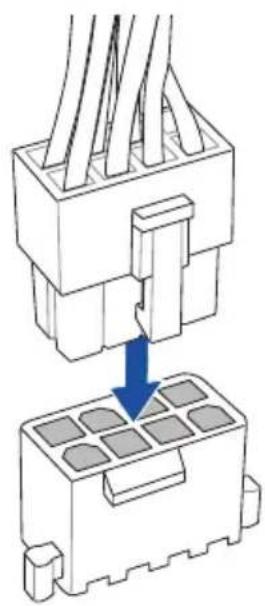
和


2.1.8 安装扩展卡
安装 PCIe x16 扩展卡

2.1.9 安装 M.2


2.1.10 安装 DIMM.2


连接立体声喇叭
![graph TD A["Audio INPUTS"] --> B["Line 1"] A --> C["Line 2"] D["Radio Station"] --> E["Line 3"] F["Radio Station"] --> G["Line 4"]](/content/2026/08/1627504/images/944fffb1ddc73148cb29db087eeaeddd452299c2a675e2e7733ddf78c790f134.jpg)
连接 2 声道喇叭
![graph TD A["AUDIO INPUTS"] --> B["Connector"] B --> C["Output"] D["Radio Station"] --> E["Switch"] F["Radio Station"] --> G["Switch"] H["Radio Station"] --> I["Switch"]](/content/2026/08/1627504/images/3965e73e7d76a4a13255b823bc73730ada8e74c09844ef4f037220bf15cdae5f.jpg)
连接 4 声道喇叭
![graph TD A["Audio Inputs"] --> B["Rear"] C["Audio Inputs"] --> D["Front"] E["Display Unit"] --> F["Three Speakers"] G["Display Unit"] --> H["Three Speakers"] I["Display Unit"] --> J["Three Speakers"]](/content/2026/08/1627504/images/6f1ab427827041c7309657aa6cb5fd61b028dd43a5f6dfaf42c2b07d590c5e84.jpg)
连接 5.1 声道喇叭
![graph TD A["Audio Inputs"] --> B["Rear"] A --> C["Front"] A --> D["Center/Subwoofer"] E["Speaker Module"] --> F["Speaker 1"] E --> G["Speaker 2"] E --> H["Speaker 3"] I["Output Port"] --> J["Speaker 4"] I --> K["Speaker 5"]](/content/2026/08/1627504/images/719a827a8435fd9317dda26b9b2c3e8bc6d24d6ca5d1a25c317b3695e05ad163.jpg)
连接 7.1 声道喇叭
![graph TD A["Speaker 1"] --> B["Audio Inputs"] C["Speaker 2"] --> D["Audio Inputs"] E["Speaker 3"] --> F["Audio Inputs"] G["Speaker 4"] --> H["Audio Inputs"] I["Speaker 5"] --> J["Audio Inputs"] K["Speaker 6"] --> L["Audio Inputs"] M["Speaker 7"] --> N["Audio Inputs"] O["Speaker 8"] --> P["Audio Inpu…](/content/2026/08/1627504/images/c06e84952737e4771b1521ae572f67696e04a1205b8fb079681276cace776976.jpg)
2.4 第一次启动电脑
滚动条
请依照以下步骤设置风扇:
3.2.5 EZ Tuning 向导

Internal CPU Power Management
这个子项目用来设置处理器比值与功能。
Intel(R) SpeedStep(tm)
CPU - Power Management Configuration
本项目用来管理与设置处理器电力。
Intel(R) SpeedStep(tm)
USB power delivery in Soft Off state (S5)
Next Boot after AC Power Loss
Boot Devices Control
Boot from Network Devices
Boot from Storage Devices
Boot from PCI-E/PCI Expansion Devices

状态说明:
Load/Save Profile from/to USB Drive
Discard Changes & Exit
Launch EFI Shell from USB devices
| Code 說明 | |
| 00 Not used | |
| 01 Power on. | Reset type detection (soft/hard). |
| 02 AP initialization before microcode loading | |
| 03 System Agent initialization before microcode loading | |
| 04 PCH initialization before microcode loading | |
| 06 Microcode loading | |
| 07 AP initialization after microcode loading | |
| 08 System Agent initialization after microcode loading | |
| 09 PCH initialization after microcode loading | |
| 0B Cache initialization | |
| 0C - 0D Reserved for future AMI SEC error codes | |
| 0E Microcode not found | |
| 0F Microcode not loaded | |
| 10 PEI Core is started | |
| 11 - 14 Pre-memory CPU initialization is started | |
| 15 - 18 Pre-memory System Agent initialization is started | |
| 19 - 1C Pre-memory PCH initialization is started | |
| 2B - 2F Memory initialization | |
| 30 Reserved for ASL (see ASL Status Codes section below) | |
| 31 Memory Installed | |
| 32 - 36 CPU post-memory initialization | |
| 37 - 3A Post-Memory System Agent initialization is started | |
| 3B - 3E Post-Memory PCH initialization is started | |
| 4F DXE IPL is started | |
| 50 - 53 | Memory initialization error. Invalid memory type or incompatible memory speed |
| 54 Unspecified memory initialization error | |
| 55 Memory not installed | |
| 56 Invalid CPU type or Speed | |
| 57 CPU mismatch | |
| 58 CPU self test failed or possible CPU cache error | |
| 59 CPU micro-code is not found or micro-code update is failed | |
| 5A Internal CPU error | |
| 5B Reset PPI is not available | |
| 5C - 5F Reserved for future AMI error codes | |
(表格续下页)
Q-Code 列表(表格续下页)
| Code 說明 | |
| E0 S3 Resume is stared (S3 Resume PPI is called by the DXE IPL) | |
| E1 S3 Boot Script execution | |
| E2 Video repost | |
| E3 OS S3 wake vector call | |
| E4 - E7 Reserved for future AMI progress codes | |
| E8 S3 Resume Failed | |
| E9 S3 Resume PPI not Found | |
| EA S3 Resume Boot Script Error | |
| EB S3 OS Wake Error | |
| EC - EF Reserved for future AMI error codes | |
| F0 Recovery condition triggered by firmware (Auto recovery) | |
| F1 Recovery condition triggered by user (Forced recovery) | |
| F2 Recovery process started | |
| F3 Recovery firmware image is found | |
| F4 Recovery firmware image is loaded | |
| F5 - F7 Reserved for future AMI progress codes | |
| F8 Recovery PPI is not available | |
| F9 Recovery capsule is not found | |
| FA Invalid recovery capsule | |
| FB - FF Reserved for future AMI error codes | |
| 60 DXE Core is started | |
| 61 NVRAM initialization | |
| 62 Installation of the PCH Runtime Services | |
| 63 - 67 CPU DXE initialization is started | |
| 68 PCI host bridge initialization | |
| 69 System Agent DXE initialization is started | |
| 6A System Agent DXE SMM initialization is started | |
| 6B - 6F System Agent DXE initialization (System Agent module specific) | |
| 70 PCH DXE initialization is started | |
| 71 PCH DXE SMM initialization is started | |
| 72 PCH devices initialization | |
| 73 - 77 PCH DXE Initialization (PCH module specific) | |
| 78 ACPI module initialization | |
| 79 CSM initialization | |
| 7A - 7F Reserved for future AMI DXE codes | |
Q-Code 列表(表格续下页)
| Code 說明 | |
| 90 Boot Device Selection (BDS) phase is started | |
| 91 Driver connecting is started | |
| 92 PCI Bus initialization is started | |
| 93 PCI Bus Hot Plug Controller Initialization | |
| 94 PCI Bus Enumeration | |
| 95 PCI Bus Request Resources | |
| 96 PCI Bus Assign Resources | |
| 97 Console Output devices connect | |
| 98 Console input devices connect | |
| 99 Super IO Initialization | |
| 9A USB initialization is started | |
| 9B USB Reset | |
| 9C USB Detect | |
| 9D USB Enable | |
| 9E - 9F Reserved for future AMI codes | |
| A0 IDE initialization is started | |
| A1 IDE Reset | |
| A2 IDE Detect | |
| A3 IDE Enable | |
| A4 SCSI initialization is started | |
| A5 SCSI Reset | |
| A6 SCSI Detect | |
| A7 SCSI Enable | |
| A8 Setup Verifying Password | |
| A9 Start of Setup | |
| AA Reserved for ASL (see ASL Status Codes section below) | |
| AB Setup Input Wait | |
| AC Reserved for ASL (see ASL Status Codes section below) | |
| AD Ready To Boot event | |
| AE Legacy Boot event | |
| AF Exit Boot Services event | |
| B0 Runtime Set Virtual Address MAP Begin | |
| B1 Runtime Set Virtual Address MAP End | |
| B2 Legacy Option ROM Initialization | |
| B3 System Reset | |
Q-Code 列表
| Code 說明 | |
| B4 USB hot plug | |
| B5 PCI bus hot plug | |
| B6 Clean-up of NVRAM | |
| B7 Configuration Reset (reset of NVRAM settings) | |
| B8 - BF Reserved for future AMI codes | |
| D0 CPU initialization error | |
| D1 System Agent initialization error | |
| D2 PCH initialization error | |
| D3 Some of the Architectural Protocols are not available | |
| D4 PCI resource allocation error. Out of Resources | |
| D5 No Space for Legacy Option ROM | |
| D6 No Console Output Devices are found | |
| D7 No Console Input Devices are found | |
| D8 Invalid password | |
| D9 Error loading Boot Option (LoadImage returned error) | |
| DA Boot Option is failed (StartImage returned error) | |
| DB Flash update is failed | |
| DC Reset protocol is not available |
ACPI/ASL 检查表
| Code 說明 | |
| 0x01 System is entering S1 sleep state | |
| 0x02 System is entering S2 sleep state | |
| 0x03 System is entering S3 sleep state | |
| 0x04 System is entering S4 sleep state | |
| 0x05 System is entering S5 sleep state | |
| 0x10 System is waking up from the S1 sleep state | |
| 0x20 System is waking up from the S2 sleep state | |
| 0x30 System is waking up from the S3 sleep state | |
| 0x40 System is waking up from the S4 sleep state | |
| 0xAC | System has transitioned into ACPI mode. Interrupt controller is in PIC mode. |
| 0xAA | System has transitioned into ACPI mode. Interrupt controller is in APIC mode. |
华硕的联络信息
Services/TechQuery?lang=zh-cn
Responsible Party: Asus Computer International
Address: 48720 Kato Rd., Fremont, CA 94538, USA
Phone / Fax No: (510)739-3777 / (510)608-4555
Identification of the assembled product: INTEL 9560NGW
Identification of the modular components used in the assembly:
Model Name: 9560NGW FCC ID: PD99560NG
This device complies with part 15 of the FCC Rules. Operation is subject to the following two conditions: (1) This device may not cause harmful interference, and (2) this device must accept any interference received, including interference that may cause undesired operation.
This equipment has been tested and found to comply with the limits for a Class B digital device, pursuant to part 15 of the FCC Rules. These limits are designed to provide reasonable protection against harmful interference in a residential installation. This equipment generates, uses and can radiate radio frequency energy and, if not installed and used in accordance with the instructions, may cause harmful interference to radio communications. However, there is no guarantee that interference will not occur in a particular installation. If this equipment does cause harmful interference to radio or television reception, which can be determined by turning the equipment off and on, the user is encouraged to try to correct the interference by one or more of the following measures:
- Reorient or relocate the receiving antenna.
- Increase the separation between the equipment and receiver.
- Consult the dealer or an experienced radio/TV technician for help.
- Connect the equipment into an outlet on a circuit different from that to which the receiver is connected.
RF exposure warning
This equipment must be installed and operated in accordance with provided instructions and the antenna(s) used for this transmitter must be installed to provide a separation distance of at least 20 cm from all persons and must not be co-located or operating in conjunction with any other antenna or transmitter. End-users and installers must be provide with antenna installation instructions and transmitter operating conditions for satisfying RF exposure compliance.
- OFFER TO PROVIDE SOURCE CODE OF CERTAIN SOFTWARE
- GOOGLE™ LICENSE TERMS
- COPYRIGHT© 2018 GOOGLE INC. ALL RIGHTS RESERVED
- 三年质保
- 全国联保
- 华硕产品质量保证卡
- 尊敬的华硕产品用户:
- 中央处理器(CPU)
- 内存设置
- 硬盘指示灯(HD_LED)
- Q-CODE 指示灯
- NODE 插座 (12-1 PIN NODE)
- 安装主板
- 将主板安装进机箱中。
- 安装 ATX 电源
- 安装扩展卡
- 安装 M
- 安装 DIMM
- 第一次启动电脑
- EZ TUNING 向导
- 状态说明:
- 华硕的联络信息
- IDENTIFICATION OF THE ASSEMBLED PRODUCT: INTEL 9560NGW
- RF EXPOSURE WARNING
Brand : ASUS
Model : ROG Maximus XI Gene
Category : Motherboard