
SKT60S - INSTALLATION INSTRUCTION - Dishwasher BAUKNECHT - Free user manual and instructions
Find the device manual for free SKT60S - INSTALLATION INSTRUCTION BAUKNECHT in PDF.
| Product Type | Filler trim kit for side-by-side installation of refrigerator and freezer |
| Brand | BAUKNECHT |
| Model | SKT60S |
| Required Opening Dimensions (W x H x D) | 24 1/4" x 74 1/2" x 24 1/4" (61.6 cm x 189.2 cm x 61.6 cm) |
| Interior Dimensions After Installation (W x H) | 61.31" x 66.85" (155.7 cm x 169.8 cm) |
| Required Electrical Supply | 115 V, 60 Hz, 15 or 20 A, grounded |
| Outlet Type | 3-prong grounded outlet |
| Required Tools | Cordless drill, 1/8" drill bit, level, Phillips screwdriver, tape measure, adhesive tape, flat-head screwdriver, safety glasses, #2 socket driver, 1/2" ratchet wrench drill bit |
| Supplied Parts | 6 protruding grille parts, 1 notched, top trim, left, right, spacer plate, trim kit assembly kit, front bracket, base grille, screws |
| Number of Parts | 9 main components + 9 screws |
| Fixing Method | Phillips countersunk pan head screws |
| Main Functions | Uniform appearance of side-by-side appliances; fill the space between refrigerator and freezer |
| Safety - Warnings | Risk of electric shock (grounded connection), risk of excessive weight (two persons required) |
| Maintenance and Cleaning | Damp cotton cloth with warm water and mild detergent; avoid abrasive cleaners |
| Number of Instruction Manual Pages | 20 pages |
| Available Languages | FR, EN, ES |
Frequently Asked Questions - SKT60S - INSTALLATION INSTRUCTION BAUKNECHT
User questions about SKT60S - INSTALLATION INSTRUCTION BAUKNECHT
0 question about this device. Answer the ones you know or ask your own.
Ask a new question about this device
Download the instructions for your Dishwasher in PDF format for free! Find your manual SKT60S - INSTALLATION INSTRUCTION - BAUKNECHT and take your electronic device back in hand. On this page are published all the documents necessary for the use of your device. SKT60S - INSTALLATION INSTRUCTION by BAUKNECHT.
USER MANUAL SKT60S - INSTALLATION INSTRUCTION BAUKNECHT
SKT60* TRIM KIT INSTALLATION INSTRUCTIONS
Plan the Installation 3
Opening Requirements 3
Tools Needed 3
Parts Supplied 3
Electrical Requirements 4
ASSEMBLY INSTRUCTIONS. 4
Assemble the Top Grill 4
Attach the Side Trim Extrusions. 4
INSTALLATION INSTRUCTIONS 5
Install the Top Grill and Trim Assembly 5
Place and Align Refrigerator and Freezer 5
Move Refrigerator and Freezer to Final Location 6
Install the Base Grille 7
Care and Cleaning. 7
INDICE
SEGURIDAD DEL JUEGO DE MARCOS SKT60* 8
Your safety and the safety of others are very important.
We have provided many important safety messages in this manual and on your appliance. Always read and obey all safety messages.

This is the safety alert symbol.
This symbol alerts you to potential hazards that can kill or hurt you and others.
All safety messages will follow the safety alert symbol and either the word "DANGER" or "WARNING."
These words mean:
DANGER
You can be killed or seriously injured if you don't immediately follow instructions.
WARNING
You can be killed or seriously injured if you don't follow instructions.
All safety messages will tell you what the potential hazard is, tell you how to reduce the chance of injury, and tell you what can happen if the instructions are not followed.
State of California Proposition 65Warnings:
WARNING: This product contains one or more chemicals known to the State of California to cause cancer.
WARNING: This product contains one or more chemicals known to the State of California to cause birth defects or other reproductive harm.
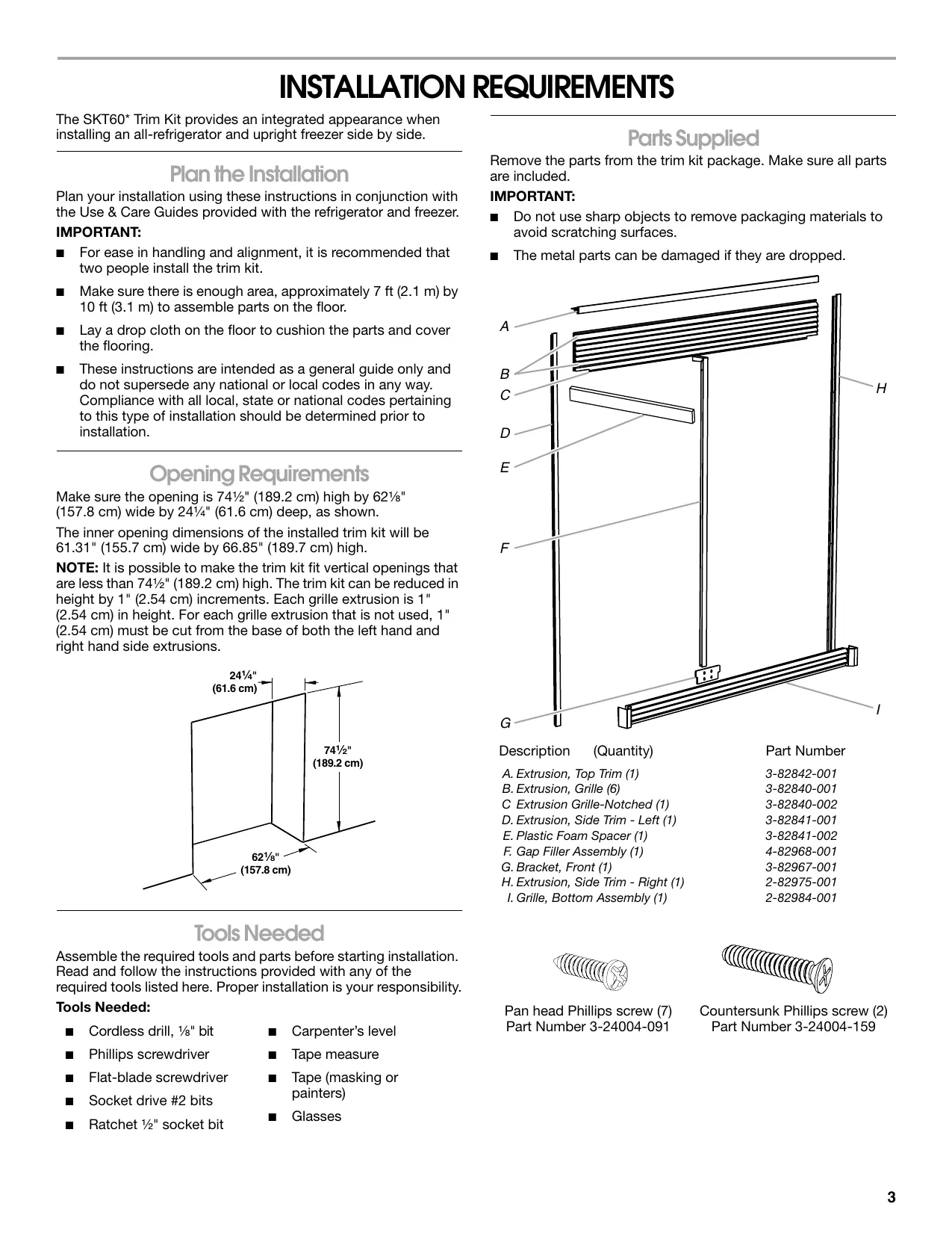
INSTALLATION REQUIREMENTS
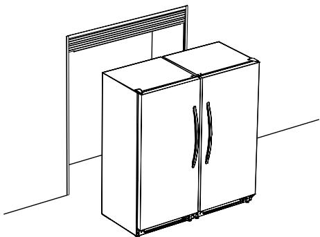
The SKT60* Trim Kit provides an integrated appearance when installing an all-refrigerator and upright freezer side by side.
Plan the Installation
Plan your installation using these instructions in conjunction with the Use & Care Guides provided with the refrigerator and freezer.
IMPORTANT:
For ease in handling and alignment, it is recommended that two people install the trim kit.
Make sure there is enough area, approximately 7 ft (2.1 m) by 10 ft (3.1 m) to assemble parts on the floor.
- Lay a drop cloth on the floor to cushion the parts and cover the flooring.
These instructions are intended as a general guide only and do not supersede any national or local codes in any way. Compliance with all local, state or national codes pertaining to this type of installation should be determined prior to installation.
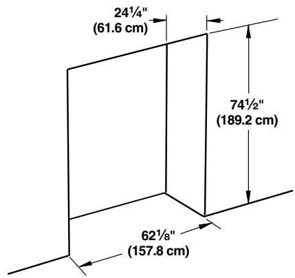
Opening Requirements
Make sure the opening is 74 12 (189.2 cm) high by 62 18 (157.8 cm) wide by 24 14 (61.6 cm) deep, as shown.
The inner opening dimensions of the installed trim kit will be 61.31" (155.7 cm) wide by 66.85" (189.7 cm) high.
NOTE: It is possible to make the trim kit fit vertical openings that are less than 74 12 (189.2 cm) high. The trim kit can be reduced in height by 1" (2.54 cm) increments. Each grille extrusion is 1" (2.54 cm) in height. For each grille extrusion that is not used, 1" (2.54 cm) must be cut from the base of both the left hand and right hand side extrusions.
Tools Needed
Assemble the required tools and parts before starting installation. Read and follow the instructions provided with any of the required tools listed here. Proper installation is your responsibility.
Tools Needed:
Cordless drill, 1/8 bit
Carpenter's level
Phillips screwdriver
Tape measure
Flat-blade screwdriver
Tape (masking or painters)
Socket drive #2 bits
Glasses
Ratchet 1 / 2 socket bit
Parts Supplied
Remove the parts from the trim kit package. Make sure all parts are included.
IMPORTANT:
- Do not use sharp objects to remove packaging materials to avoid scratching surfaces.
The metal parts can be damaged if they are dropped.
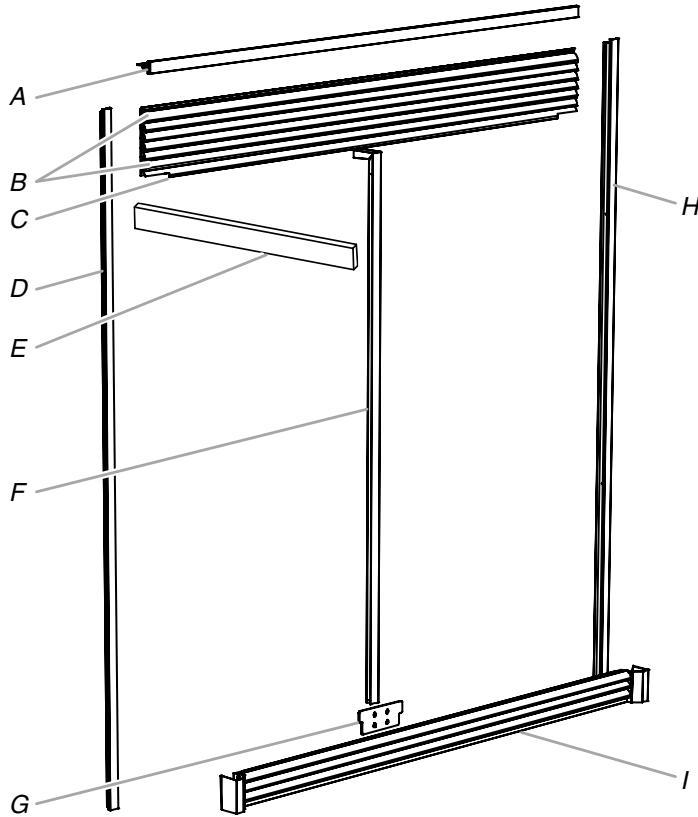
Description (Quantity)
Part Number
A. Extrusion, Top Trim (1)
3-82842-001
B. Extrusion, Grille (6)
3-82840-001
C Extrusion Grille-Notched (1)
3-82840-002
D. Extrusion, Side Trim - Left (1)
3-82841-001
E. Plastic Foam Spacer (1)
3-82841-002
F. Gap Filler Assembly (1)
4-82968-001
G.Bracket,Front(1)
3-82967-001
H. Extrusion, Side Trim - Right (1)
2-82975-001
I. Grille, Bottom Assembly (1)
2-82984-001
Pan head Phillips screw (7)
Part Number 3-24004-091
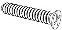
Countersunk Phillips screw (2)
Part Number 3-24004-159
Electrical Requirements
WARNING

Electrical Shock Hazard
Plug into a grounded 3 prong outlet.
Do not remove ground prong.
Do not use an adapter.
Do not use an extension cord.
Failure to follow these instructions can result in death, fire, or electrical shock.
Before you move your refrigerator and freezer into their final location, it is important to make sure you have the proper electrical connection.
Recommended grounding method
A 115 Volt, 60Hz , AC only 15- or 20-amp fused, grounded electrical supply is required. It is recommended that a separate circuit serving only your refrigerator and a separate circuit serving only your freezer be provided. Use an outlet that cannot be turned off by a switch. Do not use an extension cord.
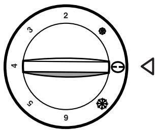
NOTE: Before performing any type of installation, cleaning, or removing a light bulb, turn the Temperature Control to the OFF position as shown and then disconnect the refrigerator from the electrical source.
ASSEMBLY INSTRUCTIONS
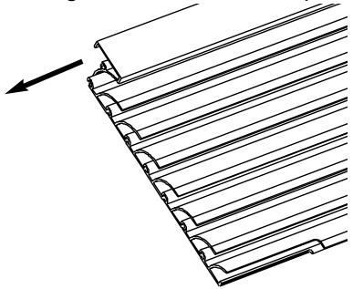
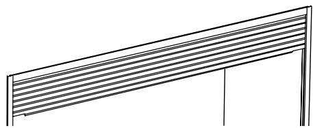
Assemble the Top Grille
- Assemble the six grille extrusions by sliding one into the other through the tongue and groove feature as shown.
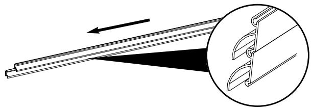
- Attach the notched grille extrusion to those already assembled by sliding it into the bottom/lowest grille.
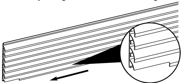
- Install the top trim extrusion onto the grille assembly by sliding it onto the grille extrusion at the top.
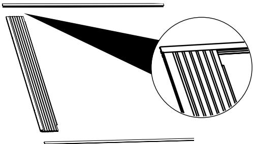
Attach the Side Trim Extrusions
- Align the side trim extrusions with the sides of the grille assembly.
NOTE: Make sure all the grille extrusions are contained within the channel of the side extrusions and the top surface of the top trim extrusion is flush with the top surface of the sides.
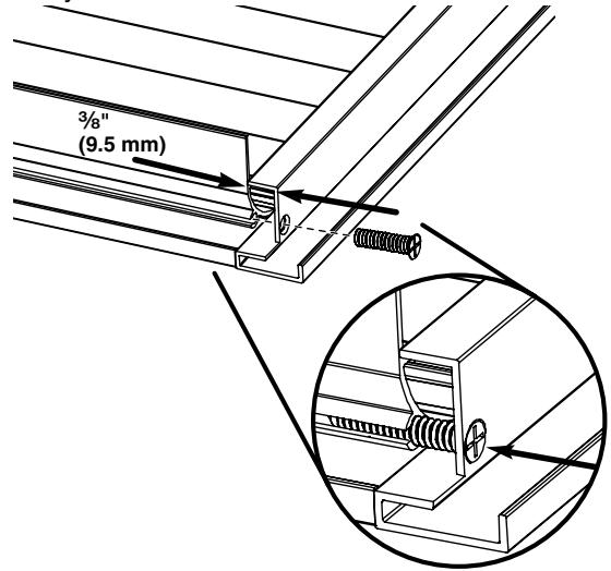
- Align the hole on the side extrusion with the groove on the top extrusion on each side of the grille assembly. There will be a 318 (9.5 mm) gap between extrusions.
- Using the two countersunk Phillips screws, fasten the side trim to the grille assembly. Insert the screw through the predrilled hole and into the groove on each side of the grille assembly as shown.
INSTALLATION INSTRUCTIONS
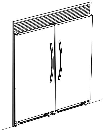
Install the Top Grille and Trim Assembly
IMPORTANT: The top grille and trim assembly, and your floor can be damaged if the assembly is dropped.
Prepare the Opening
- Place cardboard or hardboard over the floor at each side of the rough opening where the side trim will meet the floor.
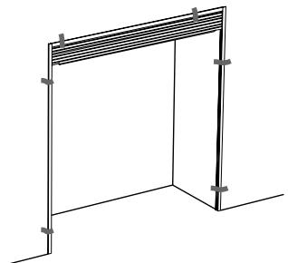
- Place the top grille and trim assembly face down on the floor centered in front of the rough opening.
- Using two people, one on each side, lift the trim assembly and position it into place above and on each side of the opening.
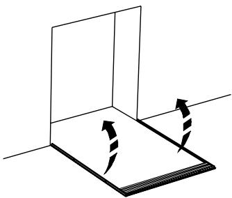
- Use several pieces of tape to temporarily hold the assembly in place as shown.
- Mark the trim assembly hole locations around the opening. Remove the tape and lower the trim assembly back to the floor.
- Using a cordless drill and 18 diameter drill bit, drill holes where marked.
NOTE: Some cabinetry or wall materials may require predrilled holes using a 7/8" diameter drill bit.
- Repeat steps 3 and 4.
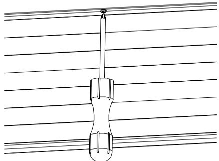
Fasten the Top Trim to the Opening
- Align the top extrusion against the opening, so that it is tight and flush with the front surface of the wall opening or cabinetry.
- From below and behind the top trim extrusion, insert a pan head Phillips screw through the predrilled center hole of the top trim and into the wall opening or cabinetry.
NOTE: Do not completely tighten the screw.
- Using a carpenter's level, level the top trim, and shim as necessary.
NOTE: Shims are not provided with the trim kit. - Using two pan head Phillips screws, fasten the top trim extrusion by inserting a screw through the predrilled holes at each end. Completely tighten the screws.
- Completely tighten the center screw.
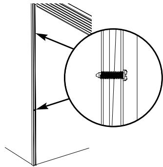
Fasten the Side Trim to the Opening
- Using a carpenters level, make sure the sides are plumb, and shim as necessary.
NOTE: Shims are not provided with the trim kit.
- Using four pan head Phillips screws (two on each side), fasten both the left-hand and right-hand side trim extrusions to the opening or cabinetry. Make sure the trim does not twist.
Place and Align Refrigerator and Freezer
WARNING
Excessive Weight Hazard
Use two or more people to move and install refrigerator.
Failure to do so can result in back or other injury.
When Moving Your Freezer or Refrigerator:
Your freezer and refrigerator are heavy. When moving the appliance for cleaning or service, be sure to cover the floor with cardboard or hardboard to avoid floor damage. Always pull the appliance straight out when moving it. Do not wiggle or "walk" the appliance when trying to move it, as floor damage could occur.
- Place the freezer and refrigerator in front of the opening (freezer on the left, refrigerator on the right).
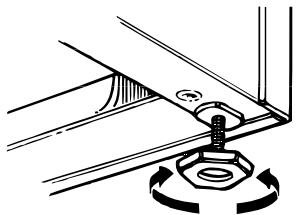
- Adjust the leveler legs so that each appliance is level and plumb and at the same height as the other appliance.
NOTE: The freezer and refrigerator each have two front leveler legs that are adjustable. The back of each cabinet rests on two fixed supports.
- Place a leveling tool on top of the cabinet. Check the level first side to side and then front to back.
To raise a corner - Turn the leveler leg clockwise.
To lower a corner - Turn the leveler leg counterclockwise.
- Repeat Step 3 for the other appliance until both the freezer and refrigerator are level, plumb and at the same height.
- Adjust the front leveler legs enough to lift the cabinet up off of the floor.
NOTE: If your model is equipped with rollers, the front legs should be lowered enough to lift the rollers off of the floor to ensure that the freezer does not roll forward when the door is opened.
Move Refrigerator and Freezer to Final Location
WARNING
Excessive Weight Hazard
Use two or more people to move and install refrigerator.
Failure to do so can result in back or other injury.
When Moving Your Freezer or Refrigerator:
Your freezer and refrigerator are heavy. When moving the appliance for cleaning or service, be sure to cover the floor with cardboard or hardboard to avoid floor damage. Always pull the appliance straight out when moving it. Do not wiggle or "walk" the appliance when trying to move it, as floor damage could occur.
IMPORTANT: If the electrical outlets are not centered in the back wall of the opening, move the appliance on the opposite side of the outlets into the opening first.
Move the First Appliance
- Cover the floor with cardboard or hardboard to avoid floor damage.
- Slide the first appliance into the opening far enough to connect the power cord to the electrical outlet.
WARNING

Electrical Shock Hazard
Plug into a grounded 3 prong outlet.
Do not remove ground prong.
Do not use an adapter.
Do not use an extension cord.
Failure to follow these instructions can result in death, fire, or electrical shock.
- Plug into a grounded 3 prong outlet.
- Check the level of the appliance since it may have changed when you moved it into the opening.
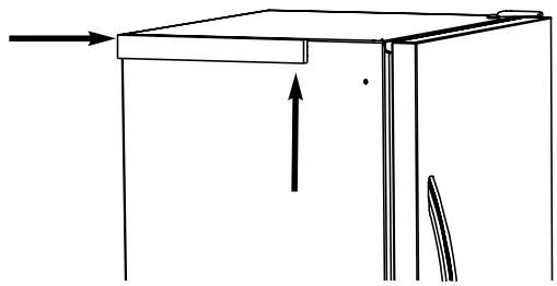
- Attach the plastic foam spacer, to the side of the appliance, so that it is flush with the top and rear edge of the cabinet as shown.
NOTE: The spacer ensures that the two appliances are positioned the correct distance apart from each other.
Move the Second Appliance
- Slide the first appliance into the opening far enough to connect the power cord to the electrical outlet.
- Plug into a grounded 3 prong outlet.
- Check the level of the appliance since it may have changed when you moved it into the opening.
NOTE: Depending on the level of the floor, you may need to remove each appliance and readjust several times to achieve a satisfactory alignment.
- If needed, either door may be adjusted vertically by loosening the three hinge bolts, moving the hinge and retightening the bolts.
NOTE: Provide additional support for the refrigerator door while the hinges are being moved. Do not depend on the door gasket magnets to hold the door in place while you are working.
- Push the refrigerator and freezer fully into the opening.
Install the Base Grille
Install the Bracket onto the Cabinets
- Remove the plastic base grille from each appliance.
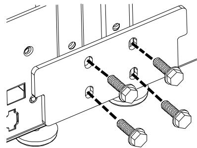
- Remove the two 5 / 16 '' hex head screws located on the opposite side from the bottom hinge on each cabinet. These will be used to fasten the bracket.
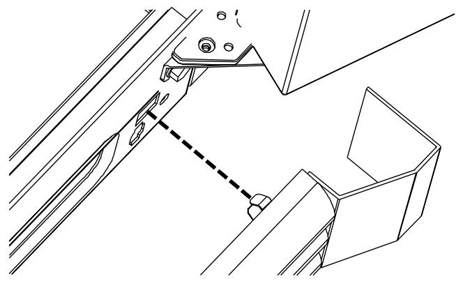
- Insert one screw through the lower bracket and thread it into the cabinet.
NOTE: Do not completely tighten the screw.
- Align the bracket holes with the holes in the appliances and install the remaining three screws.
NOTE: Do not completely tighten the screws. - Make sure the appliances are still level. Completely tighten all four bracket screws.
Install the Bottom Grille Assembly
- Align the four clips on the bottom grille assembly with the square holes in the base of the cabinets.
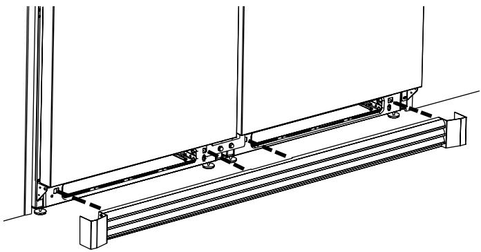
- Push and snap all the grille clips in place.
NOTE: Make sure the grille clips are fully engaged and that the base grille's side caps are situated outside the hinge bracket on each appliance.
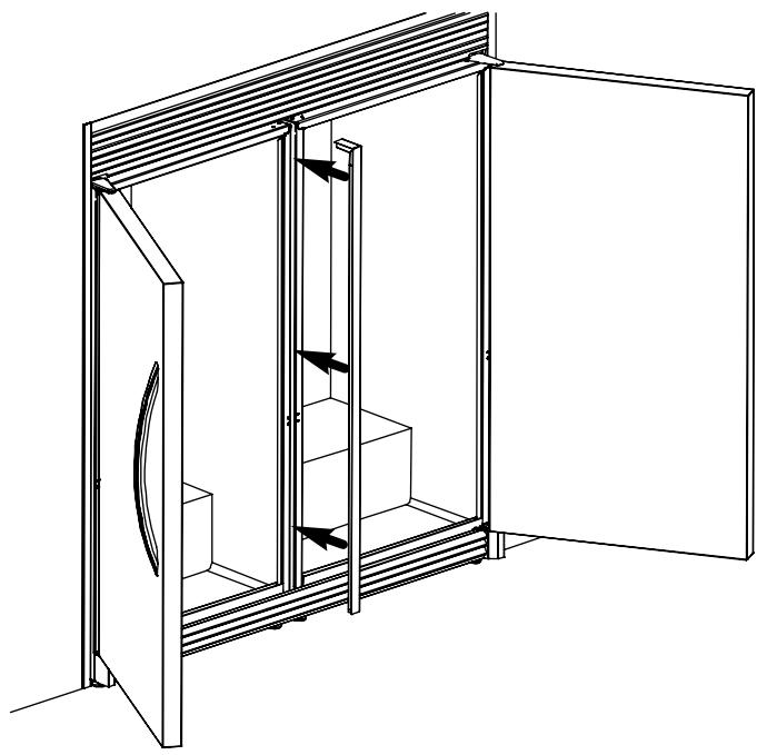
Install the Gap Filler Assembly
- Place the magnetic gap filler assembly between the refrigerator and freezer to fill in the gap between the appliances.
NOTE: The gap filler should be flush with the tops of the appliance cabinets.
Care and Cleaning
Clean the trim and grille surfaces with a cotton cloth dampened with a solution of mild dish detergent and warm water. Do not use harsh or abrasive cleaners because they will damage the metal surface of the grille and trim.