
MT4155SPS - INSTALLATION INSTRUCTION - Microwave Oven BAUKNECHT - Free user manual and instructions
Find the device manual for free MT4155SPS - INSTALLATION INSTRUCTION BAUKNECHT in PDF.
| Product Type | Built-in Microwave Oven |
| Brand | BAUKNECHT |
| Model | MT4155SPS |
| Cutout Dimensions (Width) | 22½" (57.15 cm) for 24" built-in oven; 25½" (64.77 cm) for 27"; 25½" to 28½" (64.77 to 72.39 cm) for 30" |
| Cutout Dimensions (Depth) | Min. 18½" (46.99 cm) with flush outlet; min. 19" (48.46 cm) without flush outlet |
| Cutout Dimensions (Height) | 15¾" (40.01 cm) |
| Electrical Supply | 120 V AC, 60 Hz, 15 A or 20 A, protected circuit (time-delay fuse or circuit breaker) |
| Grounding | Required: power cord with ground wire and grounding pin |
| Installation Type | Built-in above an approved electric oven |
| Compatible Built-in Oven Models | 24": RBS245PD, KEBI141D, KEBS147D; 27": (Y)RBS275PD, (Y)GBS277PD, KEBI171D, (Y)KEBS177D; 30": (Y)RBS305PD, GBS307PD, (Y)KEBI101D, (Y)KEBS107D |
| Recommended Tools | Tape measure, pencil, scissors, No. 2 Phillips screwdriver, 5/64" drill bit |
| Provided Parts | Trim frame, side duct (1), bottom duct (1), top duct (1), anti-tip bracket (1), back bracket (1), 1" screws (4+2), 1/2" screws (15+2), template |
| Main Function | Microwave cooking |
| Safety | Anti-tip device (bracket); grounding required; do not use extension cord |
| Maintenance and Cleaning | Clean with damp cloth; remove any dirt or oil before installing the ducts |
| Intended Use | Built-in above an electric oven; for household use |
Frequently Asked Questions - MT4155SPS - INSTALLATION INSTRUCTION BAUKNECHT
User questions about MT4155SPS - INSTALLATION INSTRUCTION BAUKNECHT
0 question about this device. Answer the ones you know or ask your own.
Ask a new question about this device
Download the instructions for your Microwave Oven in PDF format for free! Find your manual MT4155SPS - INSTALLATION INSTRUCTION - BAUKNECHT and take your electronic device back in hand. On this page are published all the documents necessary for the use of your device. MT4155SPS - INSTALLATION INSTRUCTION by BAUKNECHT.
USER MANUAL MT4155SPS - INSTALLATION INSTRUCTION BAUKNECHT
MICROWAVE OVEN BUILT-IN TRIM KIT INSTALLATION INSTRUCTIONS
Built-In Trim Kit Models MK1150XP, MK1154XP, MK1157XP
UL listed for use over built-in electric ovens:
24" (60.96 cm): RBS245PD, KEBI141D, KEBS147D
27" (68.6 cm): (Y)RBS275PD, (Y)GBS277PD, KEBI171D, (Y)KEBS177D
30" (76.2 cm): (Y)RBS305PD, GBS307PD, (Y)KEBI101D, (Y)KEBS107D
INSTRUCTIONS D'INSTALLATION GARNITURE ENCASTREE POUR FOUR À MICRO-ONDES
Electrical Requirements 3
Microwave Oven Preparation. 3
Bottom Duct Assembly 3
Side Duct and Upper Duct Assembly 3
Anti-Tip Bracket Installation 4
Microwave Oven Placement 4
Trim Kit Frame Installation 5
SECURITE DU FOUR À MICRO-ONDES ENCASTRÉ............5
INSTRUCTIONS D'INSTALLATION 6
Outillage recommende 6
Pièces fournies 6
Your safety and the safety of others are very important.
We have provided many important safety messages in this manual and on your appliance. Always read and obey all safety messages.

This is the safety alert symbol.
This symbol alerts you to potential hazards that can kill or hurt you and others.
All safety messages will follow the safety alert symbol and either the word "DANGER" or "WARNING."
These words mean:
DANGER
WARNING
You can be killed or seriously injured if you don't immediately follow instructions.
You can be killed or seriously injured if you don't follow instructions.
All safety messages will tell you what the potential hazard is, tell you how to reduce the chance of injury, and tell you what can happen if the instructions are not followed.
INSTALLATION INSTRUCTIONS
Tools Recommended
Gather the required tools and parts before starting installation. Read and follow the instructions provided with any tools listed here.
Measuring tape
2 Phillips screwdriver
Pencil
5%drill
Scissors
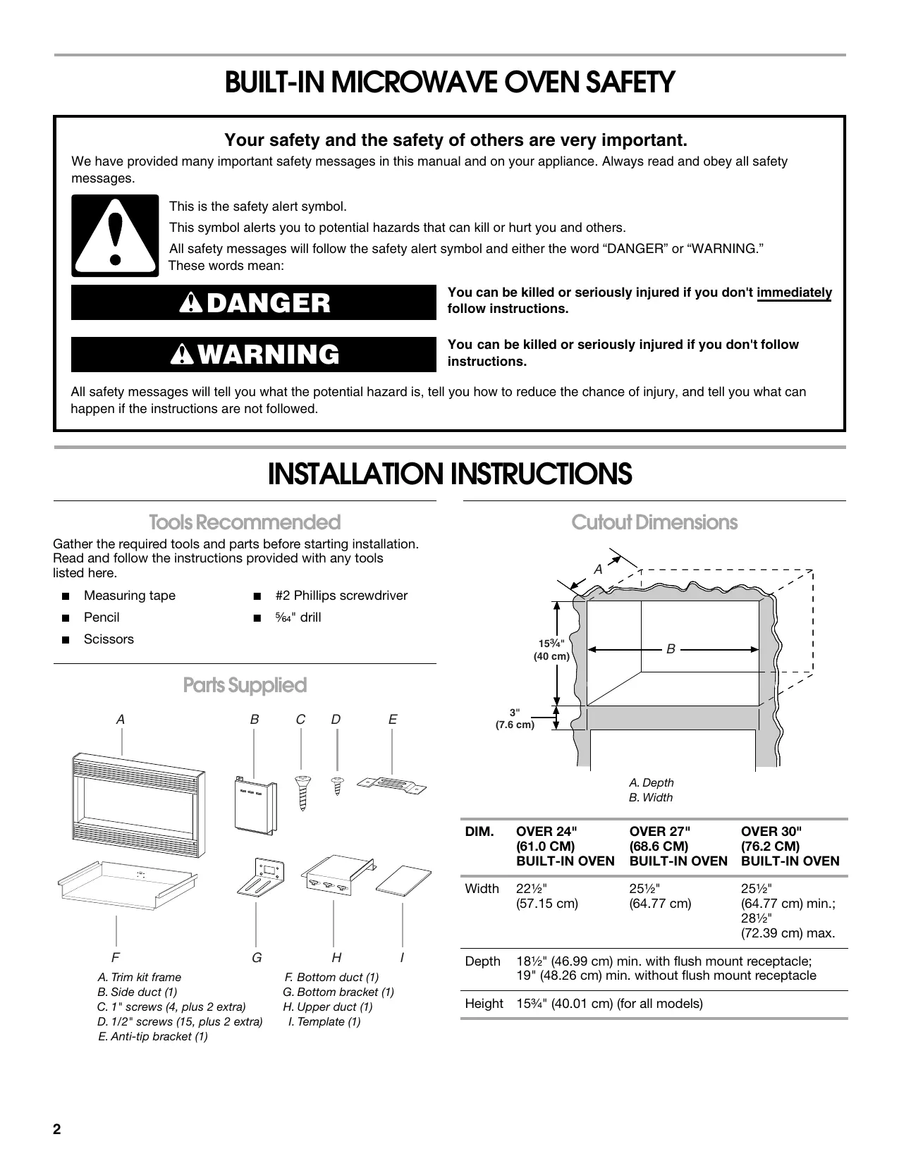
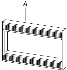
Parts Supplied
F

A. Trim kit frame
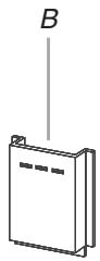
B. Side duct (1)
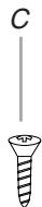
C. 1" screws (4, plus 2 extra)
D. 1 / 2 screws (15, plus 2 extra)
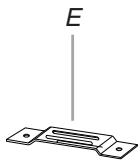
E. Anti-tip bracket (1)
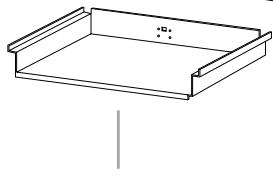
F. Bottom duct (1)
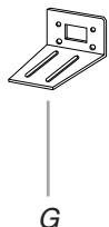
G. Bottom bracket (1)
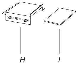
H. Upper duct (1)
I. Template (1)
Cutout Dimensions
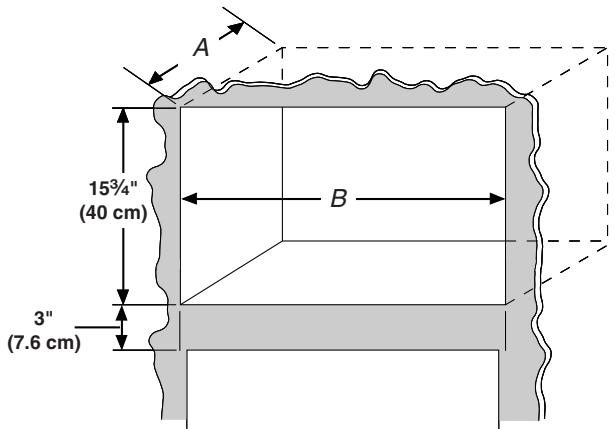
A. Depth
B. Width
| DIM. | OVER 24" (61.0 CM) BUILT-IN OVEN | OVER 27" (68.6 CM) BUILT-IN OVEN | OVER 30" (76.2 CM) BUILT-IN OVEN |
| Width | 22½" (57.15 cm) | 25½" (64.77 cm) | 25½" (64.77 cm) min.; 28½" (72.39 cm) max. |
Depth 1812 (46.99 cm) min. with flush mount receptacle; 19" (48.26 cm) min. without flush mount receptacle
Height 1534 (40.01 cm) (for all models)
WARNING

Electrical Shock Hazard
Plug into a grounded 3 prong outlet.
Do not remove ground prong.
Do not use an adapter.
Do not use an extension cord.
Failure to follow these instructions can result in death, fire, or electrical shock.
Observe all governing codes and ordinances. A 120 Volt, 60Hz , AC only, 15- or 20-amp fused electrical supply (or circuit breaker) is required. (A time-delay fuse or circuit breaker is recommended.) It is recommended that a separate circuit serving only this appliance be provided.
GROUNDING INSTRUCTIONS
For all cord connected appliances:
The microwave oven must be grounded. In the event of an electrical short circuit, grounding reduces the risk of electric shock by providing an escape wire for the electric current. The microwave oven is equipped with a cord having a grounding wire with a grounding plug. The plug must be plugged into an outlet that is properly installed and grounded.
WARNING: Improper use of the grounding plug can result in a risk of electric shock. Consult a qualified electrician or serviceman if the grounding instructions are not completely understood, or if doubt exists as to whether the microwave oven is properly grounded.
Do not use an extension cord. If the power supply cord is too short, have a qualified electrician or serviceman install an outlet near the microwave oven.
SAVE THESE INSTRUCTIONS
Microwave Oven Preparation
- Unplug microwave oven before proceeding with installation.
- Remove any loose items inside microwave oven.
Bottom Duct Assembly
- Fasten bottom bracket to bottom duct using two 12 screws.
(Rear view of bottom duct)
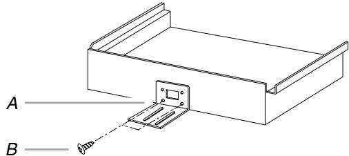
A. Bottom bracket
B. 1 / 2" screws
- Remove 2 existing screws from right side of microwave oven, and 1 existing screw from left side.
- Install bottom duct with 2 existing screws on right side of oven.
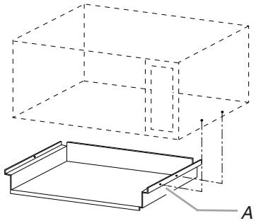
(From view of microwave oven)
A. Existing screws
Side Duct and Upper Duct Assembly
- Connect side duct to upper duct:
Insert projecting tabs of upper duct into holes of side duct. Then bend tabs upward.
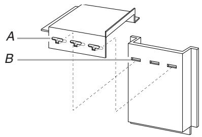
A. Tabs of upper duct
B. Holes in side duct
NOTE: Remove any dirt or oil on microwave oven surface before ducts are attached.
- Peel off backing of double-sided tape. Align the duct assembly screw hole to the existing screw hole on left side of microwave oven, and attach the duct assembly to the oven. Press down firmly on ducts, then fasten with existing screw.
A. Existing screw
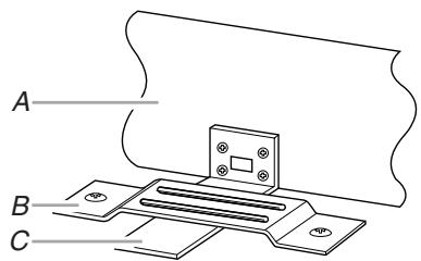
Anti-Tip Bracket Installation
- On cutout floor, use template to mark hole centers for anti-tip bracket. Be sure to align the centerline of template to centerline of cutout floor.
(Dimensions as shown are not to scale.)
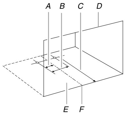
A. 1 12 (3.81 cm)
D. Cutout opening
B. 3^n (7.62 cm)
E. Cutout floor
C. 16^n (40.64 cm)
F. Centerline
- Drill 2 holes for anti-tip bracket. (Use 5 / 64 " drill.)
- Install anti-tip bracket onto cutout floor using two 12 screws.
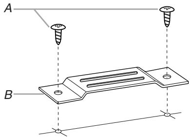
A. 1 / 2 " screws
B. Anti-tip bracket
Microwave Oven Placement
- Slide microwave oven partway into cutout opening.
NOTE: Bottom bracket must be flat against cutout floor in order to correctly engage with anti-tip bracket.
A. Bottom duct
B. Anti-tip bracket
C. Bottom bracket
- Plug in microwave oven.
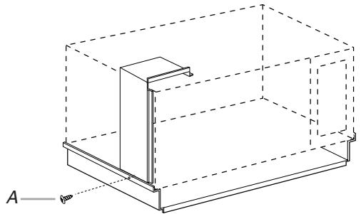
- Make sure microwave oven is centered within cutout opening and slide it into place, engaging anti-tip bracket.
- Drill pilot holes through positioning flange. (Use 5 164 drill.) Then install three 1/2 screws at front of bottom duct.
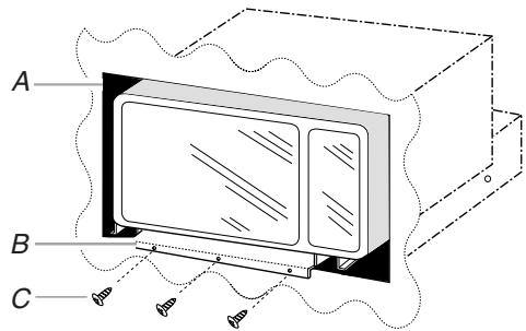
A. Cutout opening
B. Positioning flange
C. 1 / 2" screws
Trim Kit Frame Installation
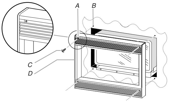
A. Mounting hole
C. 1" screw
B. Pilot hole
D. Trim kit frame
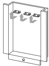
- Place trim kit frame over microwave oven.
NOTE: Trim kit frame must be oriented so that the louvers are sloping downward in the front. - Make sure the trim kit frame is level and equally centered on all 4 sides with respect to microwave oven. Mark 4 hole centers through the 4 mounting holes of trim kit frame.
- Remove trim kit frame and drill 4 pilot holes. (Use 5 / 64 " drill.)
- Attach trim kit frame using four 1" screws. Make sure orientation is correct as stated in Step 2.
Installation is now complete. Replace any loose items that have been removed from microwave oven cavity.
Save this installation instruction for future reference.
SECURITE DU FOUR À MICRO-ONDES ENCASTRÉ
Outillage recommende
C. 16'' (40,64 cm)
F. Axe central
- MICROWAVE OVEN BUILT-IN TRIM KIT INSTALLATION INSTRUCTIONS
- INSTRUCTIONS D'INSTALLATION GARNITURE ENCASTREE POUR FOUR À MICRO-ONDES
- Your safety and the safety of others are very important.
- DANGER
- WARNING
- INSTALLATION INSTRUCTIONS
- Tools Recommended
- Phillips screwdriver
- Parts Supplied
- Cutout Dimensions
- GROUNDING INSTRUCTIONS
- For all cord connected appliances:
- SAVE THESE INSTRUCTIONS
- Microwave Oven Preparation
- Bottom Duct Assembly
- Side Duct and Upper Duct Assembly
- Anti-Tip Bracket Installation
- Microwave Oven Placement
- Trim Kit Frame Installation
- SECURITE DU FOUR À MICRO-ONDES ENCASTRÉ
- Outillage recommende
Brand : BAUKNECHT
Model : MT4155SPS - INSTALLATION INSTRUCTION
Category : Microwave Oven