
SNC-VM631 - Surveillance Camera SONY - Free user manual and instructions
Find the device manual for free SNC-VM631 SONY in PDF.


| Product Type | Surveillance Camera |
| Brand | Sony |
| Model | SNC-VM631 |
| Category | Network Security Camera |
| Resolution | Up to 1920 x 1080 pixels |
| Image Sensor | 1/2.8-inch Exmor CMOS |
| Lens | Motorized varifocal lens |
| Minimum Illumination | 0.04 lux (color) |
| Compression | H.264 / MPEG-4 / JPEG |
| Frame Rate | 30 fps (max) at 1080p |
| Day/Night | True day/night with IR cut filter |
| Wide Dynamic Range | Yes, with View-DR |
| Power Supply | PoE (IEEE 802.3af) or 12 V DC |
| Power Consumption | Approx. 6.5 W |
| Operating Temperature | -10°C to +50°C (14°F to 122°F) |
| Dimensions | Approx. 73 x 63 x 137 mm (without mount) |
| Weight | Approx. 520 g |
| Network Interface | 10BASE-T/100BASE-TX Ethernet |
| Audio | Yes, via external microphone |
| Storage | MicroSD, SDHC, SDXC memory card slot |
| Security | Password protection, IP filtering, HTTPS encryption |
| Maintenance | Clean the casing with a soft, dry cloth |
| Repairability | No user-serviceable parts; contact Sony service center |
| General Information | Free user manual available for download |
Frequently Asked Questions - SNC-VM631 SONY
User questions about SNC-VM631 SONY
0 question about this device. Answer the ones you know or ask your own.
Ask a new question about this device
Download the instructions for your Surveillance Camera in PDF format for free! Find your manual SNC-VM631 - SONY and take your electronic device back in hand. On this page are published all the documents necessary for the use of your device. SNC-VM631 by SONY.
USER MANUAL SNC-VM631 SONY
Before operating the unit, please read this manual thoroughly and retain it for future reference.
Software Version 3.0
SNC-VB635/VB630/VB600/VB600B/VB632D/VB640/VB642D
SNC-VM630/VM600/VM600B/VM631/VM601/VM601B/VM632R/VM602R/VM641/VM642R
SNC-EB630/EB630B/EB600/EB600B/EB632R/EB602R/EB640/EB642R
SNC-EM630/EM600/EM631/EM601/EM632R/EM632RC/EM602R/EM602RC/EM641/EM642R
SNC-XM637/XM636/XM632/XM631
SNC-CX600W/CX600
Table of Contents
Overview
Features 4
How to Use This User's Guide .... 5
System Requirements 5
Function Chart 6
Accessing the Camera Using the Web Browser 8
Basic Configuration by the Administrator ..... 10
Precautions for Preventing Access to the Camera by an Unintended Third Party .... 11 How to set up .... 11
Operating the Camera
Administrator and User 12
Logging in to System .... 13 Logging in as a user .... 13 About Viewers .... 13
Configuration of Live Viewer .... 14 Main menu .... 14 Control panel section .... 14 Monitor image .... 16 Plug-in free viewer .... 16 Using e-Varifocal and Solid PTZ functions .... 16 Controlling via the control panel (Operation common to Area zoom mode and Vector dragging mode) .... 17
Panning and tilting by clicking the monitor image (Area zoom mode only) .... 17 Panning, tilting and zooming by specifying the area (Area zoom mode only) .... 18 Panning and tilting by dragging the screen (Vector dragging mode only) .... 18 Using pan/tilt/zoom operations with the displayed control bar (PTZ Control bar only) .... 18
Switching Transmission Mode .... 19 Playback viewer .... 20 Control panel section .... 20 Monitor image .... 22
Administrating the Camera
Basic Operations of the Administrator Menu .... 23 How to set up the Administrator menu .... 23 Configuration of the Administrator menu .... 23
Configuring the System — System Menu .... 24 Information Tab .... 24
Date & time Tab ....24 Installation Tab ....25 Initialize Tab ....26 System log Tab ....27 Access log Tab ....27 Service Tab ....28
Setting the Camera Image and Audio — Video / Audio Menu Setting the Camera Image — Video Menu ....28
Picture Tab ....29 Focus Tab — Adjusting the Focus ....31 Focus / Zoom Tab — Adjusting the focus/zoom ....31
Video codec Tab ....32 Audio Tab ....33 Superimpose Tab ....34 Day/Night Tab ....35 Privacy masking Tab ....36 Streaming Tab ....37
Configuring the Network — Network Menu .....39 Network Tab .....39 Wi-Fi Tab .....41 Wi-Fi network connection check .....41 Manual setting of a Wi-Fi network .....41 WPS settings .....42 Connection status .....42 QoS Tab .....43 UPnP Tab .....44
Setting the Security — Security Menu ....45 User Tab ....45 Access limit Tab ....46 SSL Tab ....46 How to install the CA certificate ....49 To remove an installed CA certificate ....50 To import the personal certificate ....51 802.1X Tab ....51 System configuration of 802.1X network ....52 Referer check tab ....53
Setting the PTZ control — PTZ control Menu ....54 View angle Tab ....54 Serial Tab ....55
Setting the Sensor input/Camera tampering detection/Motion detection — Action input Menu ....55
Event condition Tab ....56 Sensor input Tab — Set the sensor input 1/2 ....56 Camera tampering detection Tab — Set the camera tampering detection ....57 Motion detection Tab — Set the motion/VMF detection ....57 What is VMF ....57 Setting items for motion detection ....58
VMF settings 59
Face detection Tab — Set the face detection .... 62
Network disconnection Tab — Monitoring the connection of a specified IP address ...... 63
Setting the Action output — Action output
Menu 64
Execution Condition Tab 64
Mail Transfer Tab — Setting the e-Mail (SMTP) Function 64
Alarm output Tab — Setting the Alarm output 67
Edge Storage Tab — Setting the Edge Storage movie and still image function .... 67
Voice alert Tab 69
HTTP alarm notification Tab 70
FTP still image sending Tab 70
White LED tab 72
Setting the Schedule — Schedule Menu ...... 73
Schedule Tab 73
Others
Glossary 75
Index 77
Overview
Features
- High-quality Full HD (1080P) real-time monitoring, up to 60 fps. (SNC-VB635/VB630/VB632D/VB640/VB642D/VM630/VM631/VM632R/VM641/VM642R/EB640/EB642R/EM641/EM642R)
• High-quality Full HD (1080P) real-time monitoring, up to 30 fps. (SNC-XM637/XM636/XM632/XM631) - High-quality SXGA (1280 × 1024) live images from camera can be monitored at a maximum frame rate of 60 fps. (SNC-VB635/VB630/VB600/VB632D/VM630/VM600/VM631/VM601/VM632R/VM602R)
• High-quality HD (720P) real-time monitoring, up to 30 fps. (SNC-CX600W/CX600) - Exmor CMOS sensor enables high-quality images for streaming.
- Wide dynamic range (View-DR) and Visibility Enhancer enable clearer images for streaming in the high contrast environment.
- NR (XDNR) enables clearer images for streaming in the low lightness environment.
- Two video compression modes (video codecs) JPEG/H.264 are supported.
- The maximum triple codec mode is available.
- Easy Focus enables easier focus adjustment when it is installed. (Except SNC-EB630B/EB600B/XM637/XM636/XM632/XM631/CX600W/CX600)
- “Edge Storage” for recording of video or audio signal based on alarm detection (such as network block), and same protocol real-time image streaming. (SNC-VB635/VB630/VB600/VB600B/VB632D/VB640/VB642D/VM630/VM600/VM600B/VM631/VM601/VM632R/VM602R/VM641/VM642R/EB640/EB642R/EM641/EM642R/XM637/XM636/XM632/XM631)
- Motion detection, passive infrared motion sensor (SNC-CX600W/CX600) and camera tampering detection functions.
- At night, the color mode and intimidation function can be selected by synchronizing the white LED with the motion detection function. (SNC-VB632D/VB642D)
- Up to 20 users (SNC-CX600W/CX600: five users) can view images from one camera at the same time.
- Date/time can be superimposed on the image.
- PoE (Power over Ethernet) compliant. (except SNC-CX600W)
- The recorded movie in the memory card can be played, saved, or deleted by using the browser. (SNC-VB635/VB630/VB600/VB600B/VB632D/VB640/VB642D/VM630/VM600/VM600B/VM631/VM601/VM601B/VM632R/VM602R/VM641/VM642R/EB640/EB642R/EM641/EM642R/XM637/XM636/XM632/XM631/CX600W/CX600)
- The camera image can be sent by using Wi-Fi. (SNC-CX600W)
NOTICE TO USERS
© 2012 Sony Corporation. All rights reserved. This manual or the software described herein, in whole or in part, may not be reproduced, translated or reduced to any machine readable form without prior written approval from Sony Corporation.
SONY CORPORATION PROVIDES NO WARRANTY WITH REGARD TO THIS MANUAL, THE SOFTWARE OR OTHER INFORMATION CONTAINED HEREIN AND HEREBY EXPRESSLY DISCLAIMS ANY IMPLIED WARRANTIES OF MERCHANTABILITY OR FITNESS FOR ANY PARTICULAR PURPOSE WITH REGARD TO THIS MANUAL, THE SOFTWARE OR SUCH OTHER INFORMATION. IN NO EVENT SHALL SONY CORPORATION BE LIABLE FOR ANY INCIDENTAL, CONSEQUENTIAL OR SPECIAL DAMAGES, WHETHER BASED ON TORT, CONTRACT, OR OTHERWISE, ARISING OUT OF OR IN CONNECTION WITH THIS MANUAL, THE SOFTWARE OR OTHER INFORMATION CONTAINED HEREIN OR THE USE THEREOF.
Sony Corporation reserves the right to make any modification to this manual or the information contained herein at any time without notice. The software described herein may also be governed by the terms of a separate user license agreement.
• Is trademark of Sony Corporation.
- “Exmor” and first trademarks of Sony Corporation.
- “Exmor R” and the trademarks of Sony Corporation.
- Microsoft, Windows, Internet Explorer and Microsoft DirectX are registered trademarks of Microsoft Corporation in the United States and/or other countries.
- Java Script is a trademark of Sun Microsystems, Inc. in the United States and other countries.
- Intel Core is a registered trademark of Intel Corporation or its subsidiaries in the United States and other countries.
- Adobe, Adobe Reader and Adobe Flash are trademarks of Adobe Systems Incorporated in the United States and/or other countries.
- SD and microSD are trademarks of SD-3C and LLC.
All other company and product names are trademarks or registered trademarks of the respective companies or their respective makers.
How to Use This User's Guide
This User's Guide explains how to operate the Network Camera from a computer.
The User's Guide is designed to be read on the computer display.
This section gives tips on making the most of the User's Guide. Read it before you operate the camera.
Jumping to a related page
When you read the User's Guide on the computer display, you can click on a sentence to jump to a related page.
Software display examples
Note that the displays shown in the User's Guide are explanatory examples. Some displays may be different from the ones that appear in actual use.
The illustrations of the camera and menu display in the User's Guide show the SNC-VB600 as an example.
Printing the User's Guide
Depending on your system, certain displays or illustrations in the User's Guide, when printed out, may differ from those that appear on your screen.
Installation Manual (printed matter)
The supplied Installation Manual describes the names and functions of parts and controls of the Network
Camera, connection examples, and how to set up the camera. Be sure to read the Installation Manual before hand.
Model names
The models below are omitted in this document as their functions are equal to the relevant models.
- SNC-EM632RC is described as SNC-EM632R on the following pages.
- SNC-EM602RC is described as SNC-EM602R on the following pages.
System Requirements
The following computer environment is necessary for the computer to display images and the controls of the camera.
(August 2017)
Common
os
Microsoft Windows 7 (32-bit version, 64-bit version),
Windows 8.1 Pro (32-bit version, 64-bit version),
Windows 10 Pro (32-bit version, 64-bit version)*
Authorized editions:
Windows 7: Ultimate, Professional
Windows 8.1: Pro
Windows 10: Pro
Microsoft DirectX 9.0c or higher
Web Browser
Windows Internet Explorer Ver.11.0**
Firefox Ver. 54.0
Google Chrome Ver. 60.0
CPU
Intel Core i7, 2.8 GHz or higher
Intel Core2 Duo, 2.13 GHz or higher (SNC-CX600W/
CX600)
Memory
2 GB or more
Display
1600 × 1200 pixels or higher
* If you are on Windows 10, turn off tablet mode.
** If you are on Windows 8.1, use the Internet Explorer desktop user interface (desktop UI) edition.
Function Chart
| Model name | Maximum image size (page 32)* | High framerate mode (page 32)** | Sensor input (page 55) | Alarm output (page 67) | Edge Storage (page 67) | Audio (page 33) | IR Illuminator (page 35) | Serial control I/F (page 55) |
| SNC-VB635 | Full HD | ● | 2 | 2 | ● | ● | - | ● |
| SNC-VB630 | Full HD | ● | 2 | 2 | ● | ● | - | - |
| SNC-VB600 | HD | ● | 2 | 2 | ● | ● | - | - |
| SNC-VB600B HD - 2 2 ● | ● | - | - | |||||
| SNC-VB632D | Full HD | ● | 2 | 2 | ● | ● | ● | - |
| SNC-VB640 | Full HD | ● | 2 | 2 | ● | ● | - | - |
| SNC-VB642D | Full HD | ● | 2 | 2 | ● | ● | ● | - |
| SNC-VM630 | Full HD | ● | 2 | 2 | ● | ● | - | - |
| SNC-VM600 | HD | ● | 2 | 2 | ● | ● | - | - |
| SNC-VM600B | HD | - | 2 | 2 | ● | ● | - | - |
| SNC-VM631 | Full HD | ● | 2 | 2 | ● | ● | - | - |
| SNC-VM601 | HD | ● | 2 | 2 | ● | ● | - | - |
| SNC-VM601B | HD | - | 2 | 2 | ● | ● | - | - |
| SNC-VM632R | Full HD | ● | 2 | 2 | ● | ● | ● | - |
| SNC-VM602R | HD | ● | 2 | 2 | ● | ● | ● | - |
| SNC-VM641 | Full HD | ● | 2 | 2 | ● | ● | - | - |
| SNC-VM642R | Full HD | ● | 2 | 2 | ● | ● | ● | - |
| SNC-EB630 | Full HD - - - - - | - | ||||||
| SNC-EB630B | Full HD - - - - - | - - - - | ||||||
| SNC-EB600 | HD | - | - | - | - | - | - | - |
| SNC-EB600B | HD - - - - - | - - - - | ||||||
| SNC-EB632R | Full HD | - | - | - | - | - | ● | - |
| SNC-EB602R | HD | - | - | - | - | - | ● | - |
| SNC-EB640 | Full HD | ● | - | - | ● | ● | - | - |
| SNC-EB642R | Full HD | ● | - | - | ● | ● | ● | - |
| SNC-EM630 | Full HD | - | - | - | - | - | - | - |
| SNC-EM600 | HD | - | - | - | - | - | - | - |
| SNC-EM631 | Full HD | - | - | - | - | - | - | - |
| SNC-EM601 | HD | - | - | - | - | - | - | - |
| SNC-EM632R | Full HD | - | - | - | - | - | ● | - |
| SNC-EM602R | HD | - | - | - | - | - | ● | - |
| SNC-EM641 | Full HD | ● | - | - | ● | ● | - | - |
| SNC-EM642R | Full HD | ● | - | - | ● | ● | ● | - |
| SNC-XM637 | Full HD - - - - - | ●(only mic) | - | - | ||||
| SNC-XM636 | Full HD - - - - - | ●(only mic) | - | - | ||||
| SNC-XM632 | Full HD - - - - - | ●(only mic) | - | - | ||||
| SNC-XM631 | Full HD | - | 1 | 1 | ● | - | - | - |
| SNC-CX600W HD - - - - ● | ● | - | - | |||||
| SNC-CX600 HD | -- - ● | ● | - | - | ||||
●Usable function
- Not usable function
* Maximum image size; HD: 1280 × 1024, Full HD: 1920 × 1080, SNC-CX600W/CX600 HD: 1280 × 720
** High framerate mode: Monitoring maximum 60 frames

Accessing the Camera Using the Web Browser
After the IP address has been assigned to the camera, check that you can actually access the camera using the Web browser installed on your computer.
1 Start the Web browser on the computer and type the IP address of the camera in the URL address bar.
Address http://192.168.0.100
The live viewer window is displayed.
Display sample

Note
- The maximum number of users on the network who can see a viewer at the same time is 20 users (SNC-CX600W/CX600: five users). However, if the transmission function of the camera is overloaded, access to the camera may not be possible, even if there are fewer than the maximum number of users.
- If monitoring with sound, the maximum number of users is 10.
- When using a Wi-Fi network, it may take longer for the image to be transmitted. (SNC-CX600W)
Using the SSL function
Note
The model on sale in China does not support the SSL function.
When Internet Explorer is used
When you enter the camera IP address, "Certificate Error" may appear according to the status of the certificate set on the camera. In this case, click Continue to this website (not recommended). to continue.
The live viewer window appears (in SSL communication).
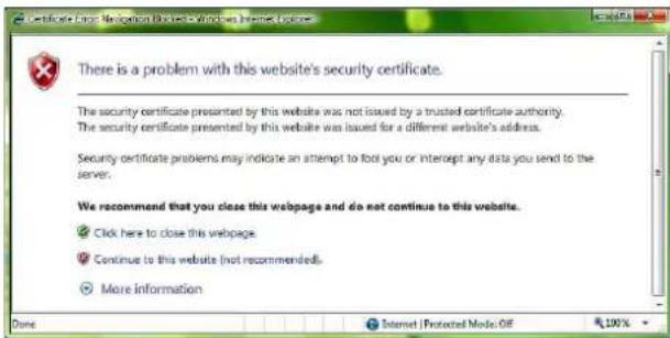
When "Allow HTTP connection for some clients" (page 47) is checked
To use HTTP and SSL connections separately to access, enter the following in the address box of the browser.
For HTTP connection
http://192.168.0.100/index.html?lang=en
For SSL connection
https://192.168.0.100/index.html?lang=en
When the live viewer of the camera is displayed for the first time
"Security Warning" is displayed. When you click Yes, ActiveX control is installed and the live viewer is displayed.

Notes
- If Automatic configuration is enabled in the Local Area Network (LAN) settings of Internet Explorer, the image may not be displayed. In that case, disable Automatic configuration and set the proxy server manually. For the setting of the proxy server, consult your network administrator.
- When you install ActiveX Control, you should be logged in to the computer as Administrator.
Tips
- The software is optimized for Internet Explorer using medium font.
- In case a part of the image cannot fit the display, configure the display setting (magnification percentage) to 100% .
If you use a display with high pixel density, the magnification percentage may be changed automatically.
To display the viewer correctly
To operate the viewer correctly, set the security level of Internet Explorer to Medium or lower, as follows:
1 Select Tools from the menu bar for Internet Explorer, then select Internet Options and click the Security tab.
2 Click the Internet icon (when using the camera via the Internet), or Local intranet icon (when using the camera via a local network).
3 Set the slider to Medium or lower. (If the slider is not displayed, click Default Level.)
When using antivirus software, etc., on the computer
- When you use antivirus software, security software, personal firewall or pop-up blocker on your computer, the camera performance may be reduced, for example, the frame rate for displaying the image may be lower.
- The Web page displayed when you log in to the camera uses JavaScript. The display of the Web page may be affected if you use antivirus software or other software described above on your computer.
Basic Configuration by the Administrator
You can monitor the camera image by logging in with the initial conditions set for this network camera. You can also set various functions according to the installing position, network conditions or purpose of the camera. We recommend you configure the following items before monitoring images from the camera.
| Setting contents Setting menu | |
| Set the format of the image sent from the camera. Video codec Tab (page 32) | |
| Select the White balance mode according to the installation position. White balance (page 30) | |
| Select the brightness of the image sent from the camera. Exposure (page 29) | Brightness (page 30) |
| Select the quality of the image sent from the camera. Video codec Tab (page 32) | |
| Select the view size of the image. View size (page 14) | |
| Select whether the audio from the external input is sent or not. Audio Tab (page 33) | |
| Synchronize the date and time of the camera with those of the computer. | Date & time Tab (page 24) |
| Make the setting for sending the monitor image attached to an e-mail. Mail Transfer Tab (page 64) | |
| Set the user access right for the camera. User Tab (page 45) | |
| Use Wi-Fi to make the setting for connecting the camera (SNC-CX600W) Wi-Fi Tab (page 41) | |
Precautions for Preventing Access to the Camera by an Unintended Third Party
The camera may be accessed by an unintended third party on the network, depending on the usage environment. Changing the user name and password of the camera administrator from the default settings is highly recommended for security reasons. If the camera is accessed by an unintended third party, there may be an undesired effect, such as operations or settings to block monitoring, etc.
The camera can be fraudulently accessed in a network environment where a device is connected or connectable to the network without the administrator's permission, or a PC or other network device connected to the network can be used without any permission. Connect to these environments at your own risk. To prevent unauthorized access to the camera, set it according to the following steps.
Do not use the browser you use to set the camera to access other websites while you set or after setting the camera. You will remain logged in to the camera as long as the browser is open, so to prevent an unintended third party's use or execution of malicious programs, close the browser after you finish setting the camera.
How to set up
1 Set the network address of the camera using SNC toolbox.
For details about how to use SNC toolbox, refer to the application guide.
After this step, do not use SNC toolbox to change the network settings of the camera. Use SNC toolbox to search for the camera only.
2 Start the web browser and set the SSL function to Enable in the camera settings.
For details, refer to “Setting the security — SSL tab on the Security menu” in the Administrator menu on page 46.
3 Restart the web browser and access the camera again.
4 Set the user name and password of the administrator of the camera. For details, refer to “Setting the security — User tab on the Security menu” in the Administrator menu on page 45.
5 Check the Referer check checkbox. For details, refer to “Setting the security — Referer check tab on the Security menu” in the Administrator menu on page 53.
6 Check the Viewer authentication box. For details, refer to "Setting the security — User tab on the Security menu" in the Administrator menu on page 45.
Hereafter, use the camera using the SSL connection. If you use the FTP still image sending function, the SSL function will be disabled, and communication content will not be coded. Do not use the FTP still image sending function if the camera is at risk of unauthorized access.
Note
The model on sale in China does not support the SSL function.
Operating the Camera
This section explains how to monitor the image from the camera using your Web browser.
The functions of the camera should be set by the Administrator. For the setting of the camera, see “Administrating the Camera” on page 23.
Administrator and User
This network camera identifies those who log in as the Administrator or User.
The Administrator can use all the functions of this network camera, including camera settings. The User can use the functions for monitoring the image and audio from the camera, and control the camera. The Viewer mode setting is used to restrict the user's access rights. There are five types of users.
Each type of user can use the corresponding functions below.
| Function Administrator | User | ||||
| Full Pan | Tilt Light View | ||||
| Monitor a live image ● ● | ● | ● | ● | ||
| View the date and time ● ● | ● | ● | ● | ||
| Control the frame rate (JPEG mode only) ● | ● | - | - | - | |
| Control the image view size ● ● | ● | ● | - | ||
| Save a still image and movie in the computer | ● | ● | ● | ● | - |
| Switch the TCP/UDP transmission mode (Available in H.264 mode only) | ● | ● | - | - | - |
| Perform the pan/tilt/zoom operation | ● | ● | ● | - | - |
| Receive audio | ● | ● | ● | ● | |
| Select the codec mode | ● | ● | ● | ● | |
| Control the setting menu | ● | - | - | - | - |
| Play the recorded file in the memory card | ● | ● | - | - | - |
| Delete the recorded file in the memory card | ● | - | - | - | - |
●Usable function
- Not usable function
The access rights of the administrator and the user can be set in “Setting the Security — Security Menu” of the Administrator menu on page 45.
Logging in to System
Logging in as a user
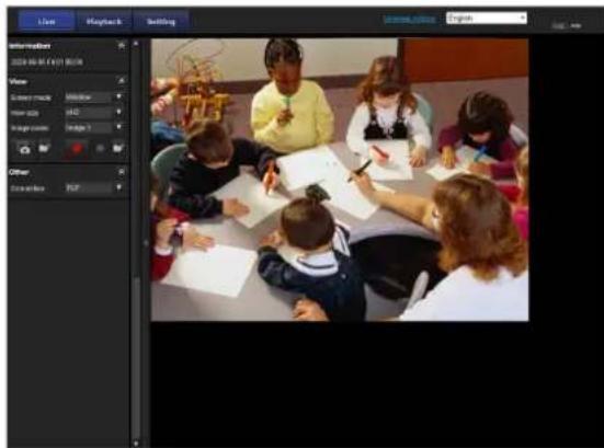
1 Start the Web browser on your computer and type the IP address of the camera you want to monitor.

The live viewer is displayed.
Display sample:
Note
If the live viewer does not start correctly, the security level of the Internet Explorer may be set to higher than Medium. See “To display the viewer correctly” on page 9 and check the security level.
About Viewers
You can use the following viewers.
ActiveX viewer
This viewer can monitor the camera image in any of the JPEG and H.264 video codecs.
Two types of ActiveX viewer are available: Live viewer and Playback viewer.
You must install this viewer when you access the viewer for the first time.
When you display the viewer of the camera for the first time
When you access the network camera using ActiveX viewer for the first time, the Security Warning appears. Click Yes and install ActiveX Control. You can use all the functions of the viewer with ActiveX Control.
Plug-in free viewer
This viewer enables a browser other than Internet Explorer to display images.
Notes
- If Automatic configuration is enabled in the Local Area Network (LAN) Settings of Internet Explorer, the camera image may not be displayed. In that case, disable Automatic configuration and set the proxy server manually. For the setting of the proxy server, consult your network administrator.
- When you install ActiveX Control, you should be logged in to the computer as the Administrator.
Tips
- Every page of this software is optimized for Internet Explorer in Medium font.
- In case a part of the image cannot fit the display, configure the display setting (magnification percentage) to 100%.
If you use a display with high pixel density, the magnification percentage may be changed automatically.
Configuration of Live Viewer
This section explains the functions of the parts and controls of the live viewer. For a detailed explanation on each part or control, see the specified pages.
Live viewer using ActiveX viewer

Main menu
Live viewer
Displays the ActiveX viewer or the Plug-in free viewer.
Playback viewer
Click to play, save and delete the recorded movie in the memory card. (page 20)
Setting
Click to display the Administrator menu. (page 23) You can operate this function only when logging in as the administrator.
License notice
Displays the software consent agreement, etc.
Language
Set language from pull-down.
Control panel section
You can drag the panels to the monitor screen and configure them.
To return to the control panel, drag the panel and configure the control panel.
Click the ↗ hide the detail setting menu or click it again to show the menu.
Information panel

Check the date and time here.
View panel

You can change the screen mode, view size of the image, image codec mode and frame rate. Also, still images and movies can be saved (movie saving can also be stopped) from here. Microphone and audio output levels can be adjusted.
Screen mode
Select Window or Full Screen.
View size
Selects the view size to be displayed.
Click View size list box to select the view size.
Select ×1/4 to display images, reduced to 1/4 of the size set in Image size.
Select ×1/2 to display images, reduced to 1/2 of the size set in Image size.
Select ×1 to display images set in Image size (page 32) of the Video / Audio menu or Video menu.
Select Full to display images according to the view size.
Select Fit to display images according to the view size, with fixed aspect ratio.
Image codec
Select Image1, Image2 and Image3 of the video codec.
Frame rate
(Displayed only when the camera image is in JPEG.) Selects the frame rate to transmit images.

Capture
Click to capture a still image shot by the camera and to store it in the computer. Click ▶ open the folder to be saved.
Note
When protection mode (Windows > Control panel > Internet options > Security property) is enabled, still images cannot be captured.

Run/ Stop Save Video
Runs and stops Save Video. Click to open the folder to be saved.
Note
When protection mode (Windows > Control panel > Internet options > Security property) is enabled, videos cannot be saved.
Volume
Displays when Enable in the Audio tab of the Video / Audio menu is checked.

Use the slide bar to adjust the volume for sound output level.
When you click 📄 the icon changes to and the output from the speaker stops. To output sound from the speaker, click 📄 in.
Mic volume
Displays when Audio upload (page 34) in the Audio tab of the Video / Audio menu is set to Enable, and a user with audio enabled in the User tab of the Security menu accesses the device.

Use the slide bar to adjust the microphone volume.
When you click 📄 the icon changes to an 📋 the microphone input stops. To input the microphone, click ✗ again.
Camera control panel

This panel allows you to control the camera's pan/tilt/home position and zoom (page 17).
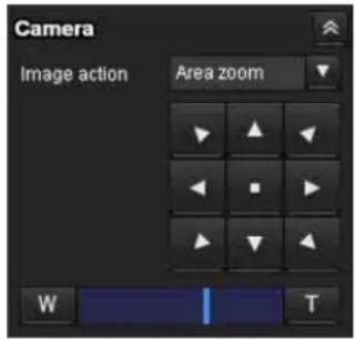
Image action
Select the mode of operation from Off, Area zoom and Vector dragging.
Pan/Tilt control
Click the arrow button the direction in which you want to move the camera. Keep it pressed to move the camera continuously.
To return to the home position, click
Zoom control
Click w zoom out, and click to zoom in. Zooming continues while the button remains pressed.
Other panel

(The Other panel is displayed in the case of an H.264 image.)
You can switch between TCP and UDP (Unicast/Multicast).
Each click switches the transmission mode of the video/audio data between TCP mode, Unicast mode, and Multicast mode (page 19).
Monitor image

The image shot by the camera is shown here.
There are two modes for on-screen pan/tilt/zoom operation using a mouse: Area zoom mode and Vector dragging mode.
In the Area zoom mode, click to adjust the camera direction to the center of the image.
The Area zoom will move the camera in the direction that displays the area selected by the operator and zooms in at the same time. The operator can choose a part of the image to view and zoom in by surrounding an area with a frame by dragging the mouse.
In the Vector dragging mode, the camera moves to the dragged direction. How long you drag the mouse determines the speed. Releasing the button on the mouse after dragging stops the panning or tilting of the camera.
You can also use the camera control panel bar to change the camera direction.
The zoom operation using the mouse wheel is available in all modes.
Plug-in free viewer
Live viewer using Plug-in free viewer
Display sample:

Control bar
Monitor screen
Monitor screen
There are two modes for on-screen pan/tilt/zoom operation using a mouse: Area zoom mode and Vector dragging mode. A control bar is displayed on the screen. In the Area zoom mode, click to adjust the camera direction to the center of the image.
The Area zoom will move the camera in the direction that displays the area selected by the operator and zooms in at the same time. The operator can choose a part of the image to view and zoom in by surrounding the area with a frame by dragging the mouse.
In the Vector dragging mode, the camera moves to the dragged direction. How long you drag the mouse determines the speed. Releasing the button on the mouse after dragging stops the panning or tilting of the camera. You can also use the tool bar to change the camera direction.
The zoom operation using the mouse wheel is available in all modes.
Control bar
The following operation buttons are available.
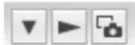
Setting
You can set the streaming method, image size, frame rate, PTZ operation mode and image codec.
Streaming start button
Starts streaming. (Appears while stops streaming.)
Streaming stop button
Stops streaming. (Appears while streaming.)
Save still image button
Captures still images taken by the camera and saves them to the computer.
Using e-Varifocal and Solid PTZ functions
You can operate the camera by using the e-Varifocal and Solid PTZ functions, which provide panning, tilting and zooming by adjusting the position and zooming ratio from the maximum image size (1280 × 720*, 1280 × 1024**, 1920 × 1080**), without moving the camera.
* 1280 × 720: SNC-CX600W/CX600
** 1280 × 1024: SNC-VB600/VB600B/VM600/VM600B/VM601/VM601B/VM602R/EB600/EB600B/EB602R/EM600/EM601/EM602R
*** 1920 × 1080: SNC-VB635/VB630/VB632D/VB640/VB642D/VM630/VM631/VM632R/VM641/VM642R/EB630/EB630B/EB632R/EB640/EB642R/EM630/EM631/EM632R/EM641/EM642R/XM637/XM636/XM632/XM631
There are three modes of camera operation: Area zoom mode, Vector dragging mode and PTZ Control bar.
You can control pan/tilt and zoom in either mode.
The available functions for the camera operation modes vary according to the live viewer display. The available functions are as follows.
| ActiveX viewer | Plug-in free viewer | ||
| JPEG MJPEG | |||
| Operation from control panel | ○ | - | - |
| Area zoom ○ | ○ | ○ | |
| Vector dragging ○ | ○ | ○ | |
| PTZ control bar | - | ○ | ○ |
Notes
- Pan/Tilt limitation
The e-Varifocal and Solid PTZ functions control streaming by cropping or reducing a maximum size image.
Thus, the more the camera zooms out, the less area to be panned or tilted, and becomes unavailable at the WIDE end.
- Zoom limitation
An e-Varifocal function adjusts the angle of image in the range with less image quality degradation by limiting the cropped range of the image to the shooting range of equal magnification size. Use the e-Varifocal function by selecting an image size other than the maximum size in the Video codec tab. Zoom limitation is changed depending on the selected image size.
The solid PTZ function enables you to display an area of 1/16 the maximum image size (Aspect ratio: 1:4), when zoomed in at the TELE end. An image cannot be enlarged beyond this.
And the whole area shot in the maximum image size will be displayed if the camera is zoomed out at the WIDE end.
The solid PTZ function's zoom is performed digitally; therefore, some deterioration in image quality may be observed at the TELE end.
- The Plug-in free viewer display method will be selected automatically.
Controlling via the control panel (Operation common to Area zoom mode and Vector dragging mode)
You can operate the camera direction and zoom by using the control panel for the monitor image currently displayed.
Pan/Tilt control
Click the arrow button in the direction in which you want to move the camera. Keep it pressed to move the camera continuously.
To return to the home position, click
Zoom control
Click to zoom out, and click to zoom in.
Zooming continues while the button remains pressed.
Note
The four edges of the image may be dark depending on the zoom position. This is a phenomenon related to the structure of the camera, and does not cause a problem.
Panning and tilting by clicking the monitor image (Area zoom mode only)
Click on the monitor image, and the camera moves so that the clicked portion is positioned at the center of the display.

Panning, tilting and zooming by specifying the area (Area zoom mode only)
Click and hold the left button of the mouse on the monitor image, and drag the mouse diagonally to draw a red frame around the portion you want to enlarge. The camera moves so that framed portion is positioned at the center of the display and is zoomed in.

Note
When the specified area is zoomed in, the center may be shifted or some portion of the image may appear out of the monitor image section. In this case, click the point you want to move to the center or click the arrow button on the camera control panel.
Panning and tilting by dragging the screen (Vector dragging mode only)
When you click on the starting point on the image and drag to the end point, the camera pans/tilts in the direction of the arrow from the starting point to the end point. The speed of operation is determined by the length of arrow. Releasing the button on the mouse stops the panning/tilting of the camera.

Using pan/tilt/zoom operations with the displayed control bar (PTZ Control bar only)

Pan/Tilt operations
Click the arrow of the direction you wish to move the camera. Continue pressing on the arrow to keep moving the direction of the camera.
Zoom operation
Click to zoom out, click to zoom in. The zoom operation continues while you are pressing on the button.
Switching Transmission Mode
You can change the transmission mode for video/audio data.
This function can be used when the video codec mode is set to H.264 and the ActiveX viewer in the live viewer is used.
Note
The function may not operate correctly if you use personal firewall software or antivirus software on your computer. In that case, disable the software or select the TCP mode.
1 Select TCP, Unicast or Multicast from the Connection drop-down list in the Other panel.

TCP: This is normally selected.
When TCP is selected, HTTP communication is adopted for video/audio communications. HTTP is the protocol used for reading the usual Web page. In an environment capable of reading Web pages, you can watch or listen to video/audio by selecting the TCP port.
Unicast: When Unicast is selected, RTP (Real-time Transport Protocol) is adopted for video/audio communications. Since RTP is the protocol for running video/audio data, the video/audio playback is smoother than when TCP (HTTP) is selected. If a firewall is installed between the camera and the computer, or depending on the network environment, video/audio may not play back properly when Unicast is selected. In this case, select TCP.
Multicast: This protocol is selectable when Multicast streaming in the Streaming tab of the Video / Audio menu or Video menu is set to Enable. When Multicast is selected as the transmission port, RTP (Real-time Transport Protocol) and UDP multicast techniques are adopted for video/audio transmission. By selecting it, the network transmission load of the camera can be reduced. If a router that does not correspond to a multicast or firewall is installed between the camera and the computer, video/audio may not play back properly. In this case, select TCP or Unicast.
Note
When connecting via a proxy server, neither Unicast nor Multicast can be selected.
Playback viewer
Supported models: SNC-VB635/VB630/VB600/VB600B/VB632D/VB640/VB642D/VM630/VM600/VM600B/VM631/VM601/VM601B/VM632R/VM602R/VM641/VM642R/EB640/EB642R/EM641/EM642R/XM637/XM636/XM632/XM631/CX600W/CX600
You can play, save or delete the movies recorded in the memory card.
This function is available only in the following users.
- Administrator
- When Viewer mode is set to Full

Control panel section
View panel

You can change the screen mode or view size of the image.
Screen mode
Select Window or Full Screen.
View size
Select the view size to be displayed.
Click the View size list box to select the view size.
Select ×1/4 to display images, reduced to 1/4 of the size set in Image size.
Select ×1/2 to display images, reduced to 1/2 of the size set in Image size.
Select ×1 to display images set in Image size (page 32) of the Video / Audio menu.
Select Full to display images in full size.
Select Fit to display images in full size with fixed aspect ratio.
Search panel

Specify the search period.
Start
Select the start time for searching.
End
Select the end time for searching.
Maximum search number
You can specify the maximum number of the search results.
Search
Search for recorded movies in the specified period.
Search results list
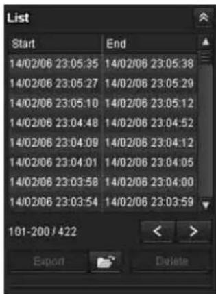
Displays the search results from the search panel. You can select the movie which you want to play, save or delete.
You can select multiple files for deletion by clicking those movies while pressing the control key.
Range of the search results displayed in the list 101-200 / 422
Indicates the list of the total search results that is currently displayed.
> Go to the next search result
Displays the next search results.
< Go to the previous search result
Displays the previous search results.
Export Save recorded movie
Save the selected movie to your computer. Click to open the folder in which the movie is to be saved.
Delete Delete recorded movie
Delete the selected movie(s).
Note
Only the administrator can delete movies. Deleted movies cannot be restored.
Control panel (Basic)

You can play, pause, stop, fast forward or jump the selected movie on the search results list. Also you can specify the start position for playback.
If you click the button, the control panel (detail) is displayed.
Control panel (Detail)
Specify the start position for playback

Specify the playback time
You can play, pause, stop, fast forward or jump the selected movie on the search results list. Also you can specify the start position for playback, playback time, save the movie or save the captured still image.
If you click the button, the control panel (basic) is displayed.
Specify the start position for playback
Move the start position by dragging the slider.
Time

Specify the recorded date and time from which the movie will start playback.
Previous record
Jump to the previous movie.
Stop button
Click this button to stop a movie playing.
Play button
Play the movie.
Click this button to play the movie at the normal speed after pressing the fast forward button.
Pause button
Click this button to pause a movie playing.
Fast forward
Click this button to fast forward the moving being played.
Next record
Jump to the next movie.
Still image capture
Save the capture of a recorded movie as a still image file to your computer. Click to open the folder in which the movie is to be saved.
Specify the playback time
Specify the start and end position of the movie by moving the slider.
You can save the specified time to your computer.
You can also specify the start time to In and end time to Out.
Export Save selected part of recorded movie
Save the part of movie which is specified by the playback time to your computer. Click to open the folder in which the movie is to be saved.

Operating the Camera
Monitor image

Play the selected movie from the search results list.
Administrating the Camera
This section explains how to set the functions of the camera by the Administrator.
For details about monitoring the camera image, see "Operating the Camera" on page 12.
This section explains the basic operations and each option of the Administrator menu.
Note on the display of menu options
The setting menus of this unit will clearly display only the setting options that you can currently select. Grayed out options cannot be selected.
Only supported functions are displayed.
Basic Operations of the Administrator Menu
You can use the Administrator menu to set all functions to suit the user's needs.
Click Setting in the viewer to display the Administrator menu.
How to set up the Administrator menu
1 Log in to the homepage to display the viewer. For details, see "Logging in as a user" on page 13.
2 Click Setting on the main menu. The authentication dialog appears. Enter the user name and password for Administrator. The Administrator menu appears. The user name “admin” and password “admin” are set at the factory for the Administrator. For security, be sure to change the password from the factory setting before using the camera. Create a user name and password using half-width characters that do not include “, (comma)”, “#”, “&”, “:” or “(space)”.
3 Click the menu name (example: System) on the left side of the Administrator menu. The clicked menu appears.
Example: "System" menu

4 Select the required tab above the menu, and set each setting option in the tab.
Example: "Date & time" tab of "System" menu

See page 24 for details of the menu tabs and setting options.
5 After setting, click OK. The settings you have made become active.
Click Cancel to nullify the set values and return to the previous settings.
Buttons common to every menu
The following buttons are displayed on all the menus.
OK
Click this button to confirm the settings.
Cancel
Click this button to nullify the set values and return to the previous settings.
General notes on menus
- Input characters (for usernames, for example) in half-width characters on a computer. Half-width katakana cannot be used.
• After changing a setting on a menu, wait at least 30 seconds before turning off the power of the camera. If the power is turned off immediately, the new setting may not be stored correctly. - If the camera settings are changed while watching the live viewer, some settings cannot be restored. To reflect the change on the opening live viewer, click Refresh on the Web browser.
Configuration of the Administrator menu
System
Displays the System menu. ("Configuring the System—System Menu" on page 24)
Video / Audio
Displays the Video / Audio menu for setting the camera image and audio. ("Setting the Camera Image and Audio — Video / Audio Menu Setting the Camera Image — Video Menu" on page 28)
Video
Displays the Video menu for setting the camera image. ("Setting the Camera Image and Audio — Video / Audio Menu Setting the Camera Image — Video Menu" on page 28)
Network
Displays the Network menu for setting the network connection. (“Configuring the Network — Network Menu” on page 39)
Security
Displays the Security menu for setting the login user name and password to specify which computer(s) can connect to the camera. (“Setting the Security — Security Menu” on page 45)
PTZ control
Displays the setting menu for view angle and serial interface. (“Setting the PTZ control — PTZ control Menu” on page 54)
Action input
Displays the setting menu for all built-in detection functions. (“Setting the Sensor input/Camera tampering detection/Motion detection — Action input Menu” on page 55)
Action output
Displays the Action output menu for setting an action of the functions such as e-Mail (SMTP) and Edge Storage. ("Setting the Action output — Action output Menu" on page 64)
Schedule
Displays the Schedule menu for the e-Mail (SMTP) function, Alarm output function, Voice alert function, etc. (“Setting the Schedule — Schedule Menu” on page 73)
Configuring the System — System Menu
When you click System Administrator menu, the System menu appears.
Use this menu to perform the principal settings of the software.
The System menu consists of the following tabs: Information, Date & time, Installation, Initialize, System log and Access log.
Information Tab

Model Name
The model name of the camera is displayed.
Serial number
The serial number of the camera is displayed.
Software version
The software version of the camera is displayed.
Date & time Tab

Current date & time
Displays the date and time set on the camera.
Note
After you have purchased the camera, be sure to check the date and time of the camera and set as necessary.
PC clock
Displays the date and time set on your computer.
Date & time format
Select the format of date and time to be displayed in the viewer from the drop-down list.
You can select the format between yyyy-mm-dd hh:mm:ss (year-month-day hour:minutes:seconds), mm-dd-yyyy hh:mm:ss (month-day-year hour:minutes:seconds), and dd-mm-yyyy hh:mm:ss (day-month-year hour:minutes:seconds).
Time setting
Select how to set the day and time.
Keep current setting: Select if you do not need to set the date and time.
Synchronize with PC: Select if you want to synchronize the camera's date and time with the computer.
Manual setting: Select if you want to set the camera's date and time manually.
Select the year, month, date, hour, minutes and seconds from each drop-down list.
Synchronize with NTP: Select if you want to synchronize the camera's date and time with those of the time server called NTP server (Network Time Protocol).
Set the NTP server when Synchronize with NTP is selected.
NTP server
Synchronize with the selected NTP server address.
Time zone
Set the time difference from Greenwich Mean Time in the area where the camera is installed.
Select the time zone in the area where the camera is installed from the drop-down list.
Manual time zone
If you select Manual in Time zone, you can set a desired time zone that is not included in the list box. The input format is compliant with IEEE 1003.1 section 8.3 standard.
Format:
stdoffset[dst[offset][,start[/time],end[/time]]] std: 3 to 100 character strings offset: time difference (displayed in +) dst: name of summer time offset: offset of summer time, default time is 1 hour start: start date and time of summer time end: end date and time of summer time Values in [ ] can be omitted.
For example:
In case of (UTC-06:00) Central Standard Time (USA and Canada);
Central Standard Time 6 Daylight Time 1, M3.2.0, M11.1.0 The name of the time zone is CentralStandardTime and the time difference is 6 hours. The name of the summer time is DaylightTime, and the summer time offset from the time difference is 1 hour, starting from the second week on Sunday in March until the first week on Sunday in November.
Automatically adjust clock for daylight saving time changes
When selected, the clock is automatically adjusted according to the daylight saving time of the selected time zone.
Note
If the time zone selected in Time zone is different from that set on the computer, the time is adjusted using the time zone difference and set on the camera.
OK/Cancel
See “Buttons common to every menu” on page 23.
Installation Tab
You can perform settings related to installation.
Auto iris responding speed
Supported models: SNC-VB635/VB630/VB600/VB600B/VB640/EB630/EB630B/EB600/EB600B/EB640
When you use a non-standard lens, adjust the speed according to the lens you use.
Select high values to make the iris respond faster, lower values to make the iris respond slower.
Stabilizer
Set the stabilizer function. Select the checkbox to display steadier images when the camera is installed in a place subject to vibration.
Notes
- When the stabilizer function is set, the angle of image taken will be smaller than usual.
- The stabilizer may not respond, depending on the amount of vibration.
- Be sure to set this function during the installation.
- Set the privacy masking position or the motion detection area, before setting the stabilizer.
Eflip
Supported models: SNC-VM630/VM600/VM600B/VM631/VM601/VM601B/VM632R/VM602R/VM641/VM642R/EM630/EM600/EM631/EM601/EM632R/EM602R/EM641/EM642R/XM637/XM636/XM632/XM631
You can display flip vertical images on the computer.
Select On/Off according to the type of installation, such as on a ceiling, or on a rack, etc.
Note
When the Eflip setting is changed, the settings in the Video codec tab of the Video / Audio menu or the Video menu are initialized.
Image rotate
You can display the rotated images on the computer. The rotation angle can be selected from 0 degree, 90 degree, and 270 degree.
Notes
- When the Image rotate settings are changed, the settings in the Video codec tab of the Video / Audio menu or the Video menu are initialized.
- When the Image rotate is set to 90 degrees or 270 degrees, the Solid PTZ and Zoom mode settings cannot be set.
- When the Solid PTZ is enabled, the Image rotate settings cannot be set.
- The camera reboots when the Image rotate is changed between 0 degrees and 90/270 degrees.
- When the Image rotate is set to 90 degrees or 270 degrees, even if the High framerate mode in the Video codec tab of the Video / Audio menu is set to On, the frame rate can be set is up to 30 fps (NTSC) or 25 fps (PAL). (Supported models: SNC-VB635/VB630/VB600/VB600B/VB632D/VB640/VB642D/VM630/VM600/VM600B/VM631/VM601/VM601B/EB640/EB642R)
- When Image rotate is set to 90 degrees or 270 degrees, full HD dual stream mode cannot be turned On (Supported models: SNC-VB635/VB630/VB632D/VB640/VB642D/VM630/VM631/VM632R/EB640/EB642R/EM630/EM631/EM632R/XM637/XM636/XM632/XM631).
Mirroring
You can display horizontally flipped images on the computer. Select the checkbox to flip the images horizontally.
Note
When the Mirroring settings are changed, the settings in the Video codec tab of the Video / Audio menu or the Video menu are initialized.
OK/Cancel
See "Buttons common to every menu" on page 23.
Initialize Tab

Reboot
Used when rebooting the system.
Click Reboot, and the message “This System will be rebooted. Are you sure?” appears. Click OK to reboot the camera. It takes about two minutes to restart.
Factory default
Resets the camera to the factory settings.
Note
If you adjust the focus after resetting to the factory settings, the optimal focus position may not be obtained. Please make sure to perform Focus reset on the Focus tab under Video Menu after resetting to the factory default. (Supported models: SNC-VB635/VB630/VB600/VB600B/VB640/EB630/EB600/EB640)
Retain current network settings
When this item is checked, only the current network settings will be retained after reset.
Click Factory default, and the message “This System will be rebooted. Are you sure?” appears.
When you click OK, the network indicator on the camera starts to blink. After adjustments of the default settings have finished, the camera reboots automatically. Do not turn off the camera until the camera reboots.
Tip
The camera can also be reset to the factory settings by turning on the power of this unit while pressing the reset button on the camera. For details, refer to the supplied Installation Manual.
Format memory card
You can format a memory card (not supplied) inserted into the card slot of the camera. When you click Format memory card, a confirming message appears. Click OK to start formatting. Any files and folders stored in the memory card will be deleted.
Notes
- Before formatting, set Edge Storage movie and Edge Storage still image in the Execution Condition tab of the Action output menu to Off, to write-protect the memory card.
- Do not activate the Format memory card function when no card is inserted into the card slot.
Backup setting data
Saves the setting data of the camera in a file.
Click Save, and follow the instructions on the Web browser to specify the folder and save the setting data of the camera.
The file name preset at the factory is “snc-vb600.cfg” for SNC-VB600.
Restore setting
Loads the stored setting data of the camera.
Click Browse... and select the file in which the setting data is stored. Click OK, and the camera is adjusted according to the loaded data.
Restore the home position settings and the privacy masking settings
If you select this, the stored setting data of the camera, the home position and the privacy masking data are loaded.
Notes
- With Restore setting, some items in the Network menu (page 39) cannot be restored.
- The following items cannot be stored or restored with Backup setting data or Restore setting.
– audio files uploaded using the SNC toolbox - a certificate to be used in the 802.1X function
- a certificate to be used in the SSL function
– superimpose logo
Focus refresh
Supported models: SNC-VB632D/VB642D/VM630/VM600/VM600B/VM631/VM601/VM601B/VM632R/VM602R/VM641/VM642R/EB632R/EB642R/EM600/EM631/EM601/EM632R/EM602R/EM641/EM642R/EB602R/EM603
Focus may move slightly due to large impacts to the camera.
Reset the focus position to the setting position by performing the refresh operation.
Manual
Click Execute to perform the refresh operation.
Schedule
Specify the time to run refresh if you perform the refresh action periodically.
Delete voice alert file
Click Delete to delete all the audio files stored in the camera.
This function is not available for SNC-XM637/XM636/XM632/XM631.
Notes
- Clicking Delete deletes all the stored audio files simultaneously. To delete a specified audio file only, perform deletion of the audio file in the corresponding Execution Condition tab of the Action output menu (page 64).
- Before deleting the audio file, set Voice alert to Off in the Execution Condition tab of the Action output menu (page 64).
Delete superimpose logo
Click Delete to delete the superimposed logo, specified by Position in the Superimpose tab of the Video / Audio menu, from the camera.
To set whether to show or hide the superimpose logo, you need to configure the setting under the Superimpose tab.
System log Tab
The data of the software activity of the camera is recorded in this log. It includes data that is useful if a problem occurs.
Click Reload to reload the latest data.
Click Log level in the list box to adjust the importance of information to be recorded in the camera as a system log.
Set the maximum record number to be recorded in the camera in Log size.
Log information can be saved as a file by clicking
Download of Download as file.
Access log Tab
The access record of the camera is displayed.
Click Reload to reload the latest data.
Click Log level in the list box to adjust the importance of information to be recorded in the camera as an access log.
Set the maximum record number to be recorded in the camera in Log size.
Log information can be saved as a file by clicking
Download of Download as file.

Service Tab
Downloads the device information data to use for service. Select the I agree to download device information. checkbox and click OK to allow downloading. Click Download and follow the instruction on the Web browser to specify the folder to save the device information of the camera. File will be saved in binary format data.
Setting the Camera Image and Audio — Video / Audio Menu Setting the Camera Image — Video Menu
When you click Video / Audio in the
Administrator menu, the Video / Audio menu or Video menu appears.
Use this menu to set the functions of the camera.
The Video / Audio menu consists of the following tabs:
SNC-VB635/VB630/VB600/VB640/EB640/VB600B: Picture, Focus, Video codec, Audio, Superimpose, Day/Night, Privacy masking and Streaming.
SNC-VB632D/VM630/VM600/VM600B/VM631/VM601/VM601B/VM632R/VM602R/VB642D/EB642R/VM641/EM641/VM642R/EM642R: Picture, Focus / Zoom, Video codec, Audio, Superimpose, Day/Night, Privacy masking and Streaming.
The Video menu consists of the following tabs:
SNC-EB630/EB600: Picture, Focus, Video codec, Superimpose, Day/Night, Privacy masking and Streaming.
SNC-EB630B/EB600B: Picture, Video codec, Superimpose, Day/Night, Privacy masking and Streaming.
SNC-EB632R/EB602R/EM630/EM600/EM631/EM601/EM632R/EM602R: Picture, Focus / Zoom, Video codec, Superimpose, Day/Night, Privacy masking and Streaming.
SNC-XM637/XM636/XM632: Picture, Video codec, Audio, Superimpose, Day/Night, Privacy masking and Streaming.
SNC-XM631: Picture, Video codec, Superimpose, Day/Night, Privacy masking and Streaming.
SNC-CX600W/CX600: Picture, Video codec, Audio, Superimpose, Privacy masking and Streaming.
Picture Tab

You can set the color conditions, exposure, etc., of the camera.
Preview screen
Preview the image and adjust the picture setting.
Picture mode
Select the combination of image quality mode to suit the camera scene.
You can set the scene to Standard, Situation Priority, Flickerless.
When the dialog appears, click OK to apply the selected picture mode. You can change the settings of image quality individually.
Standard
Set the image quality to suit variable scenes.
Situation Priority
You can set the priority to Moving object or Low noise. Priority level can also be set.
Moving object: Stabilizes images.
Low noise: Reduces noise on images especially dark scenes.
Flickerless
Select when you want to reduce the flicker on images. Set according to power frequency (50 Hz or 60 Hz) of the lighting you use.
Exposure
Adjust the settings of exposure.
Wide dynamic range (View-DR)
Unsupported models: SNC-CX600W/CX600
In high-contrast scenes such as against a back light, this function reduces overexposure and underexposure.
Select the checkbox to turn on the Wide dynamic range (View-DR) function.
Wide dynamic range (View-DR) level
Supported models: SNC-VB600/VB600B/VM600/VM600B/VM601/VM601B/VM602R/EB600/EM600/EM601/EM602R/EB602R
Using the Wide dynamic range (View-DR) function will improve visibility of bright and dark parts of an image. The level of this function is adjustable.
Notes
- To improve visibility of bright and dark parts, the camera superimposes images taken by fast shutter speed.
When you select High, the camera takes the image by superimposing 4 images.
When you select Middle, the camera takes the image by superimposing 2 images.
When the wide dynamic range (View-DR) is activating, Middle is automatically activated for models for which this option is not displayed.
When you select High or Middle, the effect of the Shutter speed function in the Picture tab of the Video / Audio menu or Video menu is limited, depending on the scene.
- When you set Wide dynamic range (View-DR) level to High, High framerate mode in the Video codec tab of the Video / Audio menu cannot be set to On. (SNC-VB600/VM600/VM601/VM602R)
- When Wide dynamic range (View-DR) is selected, High framerate mode in the Video codec tab of the Video / Audio menu or Video menu cannot be set to On. (SNC-VB635/VB630/VB632D/VB640/VB642D/VM630/VM631/VM641/VM642R/EB640/EB642R/EM641/EM642R/VM632R)
- When the Wide dynamic range (View-DR) setting is changed, the video codec setting is initialized.
Visibility Enhancer
Using the Visibility Enhancer function will make the darker part of a camera image brighter as well as automatically correct brightness and contrast to show bright parts clearly without overexposure.
Backlight compensation
Select the checkbox to enable the backlight compensation function.
Exposure compensation
Select the exposure correction value from the list box to adjust the target brightness for the automatic exposure setting. A larger value brightens the image, and a smaller value darkens the image.
Auto gain Max. value
Limit the maximum value of gain-controlled automatic exposure control.
Note
The value shown in the auto gain maximum rate is a standard value, and may differ from the actual one.
Shutter speed
Auto-controlled shutter speed automatically sets the exposure.
Select the minimum and maximum shutter speeds from the list box.
Notes
Supported models: SNC-VB630/VB632D/VB640/VB642D/VM630/VM631/VM632R/VM641/VM642R/EB630/EB630B/EB632R/EB640/EB642R/EM630/EM631/EM632R/EM641/EM642R/XM637/XM636/XM632/XM631
When Wide dynamic range (View-DR) is selected, the shutter speed setting is not reflected.
Supported models: SNC-VB600/VB600B/VM600/VM600B/VM601/VM601B/VM602R/EB600/EB602R/EM600/EM601/EM602R
When Wide dynamic range (View-DR) is selected and Wide dynamic range (View-DR) level is set to High, the shutter speed setting is not reflected.
White balance
Mode
Select the White balance mode.
ATW: Eliminating the influences caused by environmental illumination or lights, adjust the white balance automatically to reproduce original colors of the objects (approximately 2000 K to 10000 K).
ATW-PRO: Automatically adjusts the color to be closest to the image you are viewing (approximately 2500 K to 6000 K).
When ATW or ATW-PRO is selected, R gain offset and B gain offset become effective.
Indoor: Sets a white balance suitable for indoor photography.
Outdoor: Sets a white balance suitable for outdoor photography.
Fluorescent lamp: Sets a white balance suitable for photography under three-band fluorescent lighting with a neutral white color.
Mercury lamp: Sets a white balance suitable for photography under a mercury lamp.
Sodium vapour lamp: Sets a white balance suitable for photography under a high-pressure sodium vapor lamp.
Metal halide lamp: Sets a white balance suitable for photography under a metal halide lamp.
White LED: Sets a white balance suitable for photography under the light of white LEDs.
One push WB: The One push trigger button becomes active. Click On to adjust the white balance instantly.
Manual: When this option is selected, R gain and B gain become active. Selectable gain values are from 0 to 4095.
Picture
NR (XDNR)
Select the level to reduce image noise. When you select Off, the NR function is not available.
Brightness
Set the brightness. Select high values to make the image brighter, lower values to make the image darker.
Saturation
Set the saturation. Select high values to make the image color stronger, lower values to make the image color weaker.
Notes
Supported models: SNC-CX600W/CX600
- The image color may not change if the subject is in a dark place.
- When the selected value is not 0, the image color may change after the brightness is changed.
Sharpness
Set the sharpness. Select high values to make the image edges sharper, lower values to make the image edges smoother.
Contrast
Set the contrast. Select high values to make the image contrast stronger, lower values to make the image contrast softer.
Camera operating mode (SNC-XM637/XM636/XM632/XM631/CX600W/CX600)
You can switch the operating modes of the camera. Select either 25 fps or 30 fps.
The settings of the camera operating mode are related to the frame rate selected in the Video codec tab.
OK/Cancel
See "Buttons common to every menu" on page 23.
Focus Tab — Adjusting the Focus

Supported models: SNC-VB635/VB630/VB600/VB600B/VB640/EB630/EB640/EB600
Preview screen
Preview the image and adjust the focus.
Easy Focus
Adjust the focus position.
Click the Start button to adjust the focus position automatically.
Focus
The most suitable focus position may not be available depending on imaging conditions. If so, adjust the focus position manually.
Note
Use Focus only when Easy Focus cannot be set to the most suitable focus position.
Tip
When adjusting manually, open an iris and adjust the focus position to prevent the defocusing in the dark. To open an iris, set the Fastest value to 1/10000 seconds for the Shutter speed in the Picture tab.
Focus reset
Click the On button to return to the default flange back position.
Focus / Zoom Tab — Adjusting the focus/zoom
Display sample: SNC-VM630
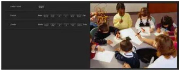
Supported models: SNC-VB632D/VB642D/VM630/VM600/VM600B/VM631/VM601/VM601B/VM632R/VM602R/VM641/VM642R/EB632R/EB642R/EM630/EM600/EM631/EM601/EM632R/EM602R/EM641/EM642R/EB602R Adjust the focus and zoom position by looking at the image.
Preview screen
Preview the image and adjust the focus/zoom.
Easy Focus
Adjust the focus position.
Click the Start button to adjust the focus position automatically.
Focus
The most suitable focus position may not be available depending on imaging conditions. If so, adjust the focus position manually.
Note
The most suitable focus may not be available depending on imaging conditions. If so, click the <<<, <<, <, >, >>, >>> buttons to adjust the focus.
Tip
When adjusting manually, open an iris and adjust the focus position to prevent the defocusing in the dark. To open an iris, set the Fastest value to 1/10000 seconds for the Shutter speed in the Picture tab.
Zoom
Click the button to adjust the zoom position accordingly.
Zoom position
Input the numeric value to adjust the zoom position.
Note
Focus will move out of position after the adjustment of the zoom and zoom position. Perform focus adjustment.
Video codec Tab
Use this tab to set the items for the video codec.
Full HD dual stream mode
Supported models: SNC-VB635/VB630/VB632D/VB640/VB642D/VM630/VM631/VM632R/VM641/VM642R/EB630/EB630B/EB632R/EB640/EB642R/EM630/EM631/EM632R/EM641/EM642R/XM636/XM632/XM631/XM637
When you set this On, the highest resolution which can be set on Image 2 will be 1920 × 1080 .
When you set this Off, the highest resolution which can be set on Image 2 will be 1280 × 720 .
Notes
- When you set this On, the image rotate setting cannot be changed to 90 degrees or 270 degrees.
- When you set this On, High framerate mode cannot be set to On. (SNC-VB635/VB630/VB632D/VB640/VB642D/VM630/VM631/VM641/VM642R/EB640/EB642R/EM641/EM642R/VM632R)
High framerate mode
Supported models: SNC-VB635/VB630/VB600/VB632D/VB640/VB642D/VM630/VM600/VM631/VM601/VM632R/VM641/VM642R/EB640/EB642R/EM641/EM642R/VM602R
When the setting is set to On, set the maximum frame rate to 60 fps (NTSC) or 50 fps (PAL).
When the setting is set to Off, the maximum frame rate is 30 fps (NTSC) or 25 fps (PAL).
For details about how to switch NTSC/PAL, refer to the supplied Installation Manual.
Notes
- When the setting is set to On, Image 2 may not be available, and Image 3 is not available.
- When the high framerate mode setting is changed, settings for Image 1, Image 2, and Image 3 are returned to the default settings.
-
When Wide dynamic range (View-DR) level in the Picture tab of the Video / Audio menu is set to High, you cannot select On. (SNC-VB600/VM600/VM601/VM602R)
-
When Wide dynamic range (View-DR) in the Picture tab of the Video / Audio menu is set, you cannot select On. (SNC-VB635/VB630/VB632D/VB640/VB642D/VM630/VM631/VM641/VM642R/EB640/EB642R/EM641/EM642R/VM632R)
- When you set this On, Full HD dual stream mode cannot be set to On. (SNC-VB635/VB630/VB632D/VB640/VB642D/VM630/VM631/VM641/VM642R/EB640/EB642R/EM641/EM642R/VM632R)
Image 1, Image 2 and Image 3
Up to three image codec modes can be set. Configure the following setting for each image mode.
Image codec
Select H.264, JPEG or Off. Note that Image 1 cannot be set to Off.
Note
The selectable size of images and frame rate for Image 2 and Image 3 may be limited, depending on the setting of codec type, image size, frame rate, and image quality for Image 1.
• The total of frame rate for Image 1, Image 2 and Image 3 should not exceed 60 fps.
- If you set the bitrate of Image 1 to 32000 kbps, set Image 2 and Image 3 to Off.
- If you set the bitrate of Image 1 to 16000 kbps or faster, set the bitrate of Image 2 and Image 3 below 4000 kbps.
If you set a value exceeding the standard, the following symptoms may occur.
• The image delays more than usual.
• The frame is skipped when playing an image.
• The voice is broken.
- The response of the camera to commands delays.
Image size
You can select the size of images sent from the camera.
Notes
- Some parts of the screen may not be displayed depending on the image size.
- If the image size is 720 × 574 or 720 × 480 , the full image is displayed but not in the 1:1 pixel aspect ratio.
Frame rate
Set the frame rate of the image.
“fps” is a unit indicating the number of frames transmitted per second.
The frame rate of JPEG image can be changed by the setting of Image quality.
I-picture interval
Set the I-picture insertion interval.
Select Time to set in seconds.
Select Frame to set in frames.
H.264 profile
Set the profile setting for H.264 video codec to high, main or baseline. The video compression efficiency is high, main and baseline in sequence. The specified profile may not be available depending on the program you use. Select the profile which is suitable for your program.
Bit rate compression mode
Select CBR, VBR or Adaptive rate control.
If you want to keep the bit rate fixed, select CBR. If you want to keep the image quality fixed, select VBR. If you select Adaptive rate control, the bit rate is automatically optimized for unstable network connections or wireless networks with a lot of interference.
Notes
- The frame rate or bit rate that is actually transmitted may be different from the set values depending on image size, scene, network environment.
- The Adaptive rate control cannot operate when the Plug-in free viewer is being used.
- If you want to use the Adaptive rate control, set the connection method in the live viewer to Unicast. If you set TCP as a connection method, the adaptive rate control will be disabled. For details, refer to “Switching Transmission Mode” in “Operating the Camera” on page 19.
Bit rate
When you set Image codec to H.264 and set Bit rate compression mode to CBR, the bit rate of the image transmission for a line can be set.
When the bit rate is set to a high level, a high image quality can be enjoyed.
Maximum bit rate limit
Enable the check box when Bit rate compression mode is set to VBR, to set the maximum value of the bit rate.
Max: Set the maximum value of the bit rate when the camera is operated with VBR.
Accept frame skip: If you enable the checkbox, the frame skip will be allowed for bit rate control.
Min, Max
Set the maximum and minimum bit rates that are adjusted with the adaptive rate mode when Bit rate compression mode is set to Adaptive rate control.
Image quality
If you set Image codec to JPEG, or Bit rate compression mode to VBR when Image codec is set to H.264, the image quality setting will be enabled.
Selectable values are from 1 to 10. When 10 is selected, the best image quality is achieved.
Bandwidth control
Limits the network bandwidth for the JPEG image data output from the camera when you set Image codec to JPEG.
Note
Audio may be interrupted depending on the selected bandwidth. In this case, select a wider bandwidth. This function is not available when the setting is set to 0.
OK/Cancel
See “Buttons common to every menu” on page 23.
Audio Tab

Audio sending
Make settings for sending audio from the microphone input connector or the built-in microphone.
Enable
Select the checkbox if you want to send audio from the network camera.
Note
When you change the Audio setting, click Refresh on the Web browser to reflect the change on the opening live viewer page.
Audio in
Select microphone input or line input. SNC-XM637/XM636/XM632/CX600W/CX600 models only have a built-in microphone. An audio cannot be selected.
Mic volume
When the Audio in is set to the microphone input, set the volume level of the audio input from the microphone
input connector or the built-in microphone. It is adjustable from -10 to +10.
Audio codec
Select the codec type for sending audio input from the microphone input connector or the built-in microphone. The bit rate may differ, depending on the codec type.
Note
No audio is output if the Plug-in free viewer is used.
Audio upload
You can output audio that is input to your computer's audio input terminal to the speaker connected to the line output jack of the camera or the built-in speaker of the camera. This function is not available for SNC-XM637/XM636/XM632/XM631.
Enable
Select the checkbox to enable the audio upload function.
Volume
Set the speaker volume level from -10 to +10.
OK/Cancel
See “Buttons common to every menu” on page 23.
Superimpose Tab

Select whether or not to superimpose the custom string and the character date & time on the image.
You can set the superimpose on/off, font sizes, and display items to display for Image 1, Image 2, and Image 3 separately in this camera.
Notes
- For setting the superimposing, set Image size1 in the Video codec tab of the Video / Audio menu or Video menu to the maximum rate.
- Deselect the checkbox of Stabilizer in the Installation tab of the System menu. After setting superimpose, set the Stabilizer function again.
Preview screen
Preview the image, and adjust the superimposed image. You can move the position of superimposed image displayed on the preview screen by drag and drop.
Image
Select the video codec mode to set for the superimposed image.
The setting for the superimposed image is available if you select the checkbox next to the list box.
For details about the video codec mode, see the Video codec tab in the Video / Audio menu or Video menu.
Position
Select the number of the display position or logo, on the preview screen. When Logo is selected, the logo file setting is displayed.
Note
Permissible logo file specifications;
File format: PNG8 with alpha channel
Image size: 640 × 120 or smaller (Image 1, Image 2) 160 × 120 or smaller (Image 3)
Width (pixels): multiples of 16
When the Image rotate in the Installation tab of the System menu is set to 90 degrees or 270 degrees, set the width pixels to a multiple of 16.
When display position number 1, 2 or 3 is selected, the following setting menus appear.
Type
Set the type of display information to codec, date & time, event or text.
Text: Displays the custom string.
Date & time: Displays the date and time.
Event: Displays the event alarm information.
Codec: Displays the video codec information.
Custom string
Describes the superimposed content for each position. For Type setting, codec is displayed as
Text color
Select the font color of the superimposed text.
Background color
Select the background color of the superimposed text.
Alignment
Set the horizontal position of the superimposed text.
Transparent
Select the background color transparent of the superimposed text. When you select Off, transparent is not available.
Font size
You can select the font size of the superimposed text and set the font size for Image 1, 2, and 3 separately. If Auto is selected, the font size is adjusted to suit the image size of the image number.
Events displayed
Displays in the menu when the type is set to Event. Select the type of superimpose to be displayed for the event.
OK/Cancel
See “Buttons common to every menu” on page 23.
Day/Night Tab
Use this tab to set the day/night function of the camera.
Mode
Select the day/night mode. This function has the following modes.
Auto: Normally works in day mode; switches automatically to night mode in a dark place.
Sync with IR Illuminator
Supported models: SNC-VB632D/VB642D/VM632R/VM602R/VM642R/EB632R/EB642R/EM632R/EM602R/EM642R/EB602R
On: The irradiator works in conjunction with day/night switching.
Off: Deactivate the irradiator.
IR Illuminator level
Supported models: SNC-VB632D/VB642D/VM632R/VM602R/VM642R/EB632R/EB642R/EM632R/EM602R/EM642R/EB602R
This setting is available when Sync with IR Illuminator is set to On.
Set the infrared intensity of the irradiator.
Note
When the IR illuminator is used, close-up objects in images may have blown out highlights. If you want to avoid blown out highlights, select Wide dynamic range (View-DR) in the Video/Audio menu or Video menu.
Threshold
Set the brightness level when the night mode is set. For SNC-VB632D/VB642D/VM632R/VM602R/VM642R/EB632R/EB642R/EM632R/EM602R/EM642R/EB602R, this setting is available when Sync with IR Illuminator is set to Off.
Brightness threshold
Supported models: SNC-VB632D/VB642D/VM632R/VM602R/VM642R/EB632R/EB642R/EM632R/EM602R/EM642R/EB602R
This setting is available when Sync with IR Illuminator is set to On.
Set the brightness level when the night mode is set.
Hold time
Set the reaction time of changes in brightness.
Manual: Switch the day/night mode manually. When the checkbox of the night mode is selected, the camera works in night mode. Otherwise, the camera works in day mode.
Timer: Normally the camera works in day mode. It switches to night mode at the time you set in Timer of Day/Night in the Schedule menu.
Sensor input:
Supported models: SNC-VB635/VB630/VB600/VB600B/VB632D/VB640/VB642D/VM630/VM600/VM600B/VM631/VM601/VM601B/VM632R/VM602R/VM641/VM642R/XM631
Controls the day/night mode by synchronizing it with the sensor input.
Select the synchronized sensor from Sensor input 1 and Sensor input 2. While a sensor input is detected, the camera works in night mode. (Only Sensor input 1 is available for SNC-XM631.)
Status
Displays the day/night function status.
Easy Focus
If you check Day/Night Sync, Easy Focus will operate together with Day/Night switching, and the focus will be automatically adjusted.
For details about Easy Focus, refer to “Focus Tab — Adjusting the Focus” on page 31 and “Focus / Zoom Tab — Adjusting the focus/zoom” on page 31.
Notes
- The image goes out of focus while Easy Focus is operating.
- The motion detection alarm does not work while Easy Focus is operating.
- If you want to check Day/Night Sync, check if the image is in focus under the monitoring environment for Day/Night mode in advance.
OK/Cancel
See "Buttons common to every menu" on page 23.
Privacy masking Tab
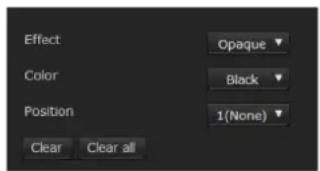
Using the privacy masking enables you to hide images by masking specified parts of the images when streaming.
Note
Perform the following before setting the privacy masking.
- Set Image size1 in the Video codec tab of the Video / Audio menu or Video menu to the maximum rate.
- Deselect the checkbox of Image 1 in the PTZ control tab of the PTZ control menu.
- Deselect the checkbox of Stabilizer in the Installation tab of the System menu. After setting the privacy masking, set the Stabilizer function again.
Preview screen
This screen is for monitoring images and configuring privacy masking.
You can move the position of the privacy mask displayed on the preview screen by drag and drop.
Effect
Set the effect of privacy masks.
Color
Specify the color of privacy masks. This setting is common to every privacy mask.
Position
Select the number corresponding to the display position on the preview screen.
After completing the configuration, register by clicking OK.
Clear
Click the button to delete the privacy mask set in Position.
Clear all
Click the button to delete all privacy mask.
Setting a privacy mask
Operate according to the following procedure to set a privacy mask in the position of your choice:
1 Select the number to register from the Position drop-down list.
2 Specify the privacy mask area by dragging the mouse on the preview screen.
3 Select the effect and color of the mask from the Effect and Color drop-down list.
Note
The color is common to every privacy mask. The color selected last is applied.
4 Click OK.
The mask is displayed on the preview screen.
OK/Cancel
See "Buttons common to every menu" on page 23.
Streaming Tab
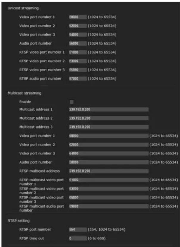
Use this tab to set the items for the transmission by unicast or multicast.
Unicast streaming
Specify the transmission port numbers of the H.264 video data and audio data to be used when Unicast is selected from the Connection drop-down list in the Other panel on the live viewer.
Video port number 1, 2, 3
Specify the transmission port number of the H.264 video data. The default setting is 50000, 52000 or 54000. Specify an even number from 1024 to 65534. Two port numbers (the number specified here and an odd number with 1 added to the specified number) are actually used for video data communication and control. When performing simultaneous multi-transmission, a different port number will be used for every transmission, based on the port number specified here. The settings for Image 1, Image 2 and Image 3 apply to Video port number 1, 2 and 3 respectively.
Audio port number
Specify the transmission port number of the audio data. It is initially set to 56000. Specify an even number from 1024 to 65534. Two port numbers (the number specified here and an odd number with 1 added to the specified number) are used for audio data communication and control. When operating multi-transmission at the same time, a different port number will be used in every transmission based on the port number specified here.
Note
Specify different numbers for the video port number and the audio port number.
RTSP video port number 1, 2, 3
Specify the H.264 video transmission port number used for RTSP unicast streaming. The default setting is 51000, 53000 or 55000. Specify an even number from 1024 to 65534. Two port numbers (the number specified here and an odd number with 1 added to the specified number) are actually used for video data communication and control. When performing simultaneous multi-transmission, a different port number will be used for every transmission, based on the port number specified here.
The settings for Image 1, Image 2 and Image 3 apply to RTSP video port number 1, 2 and 3 respectively.
RTSP audio port number
Specify the audio transmission port number used for RTSP unicast streaming. The default setting is 57000. Specify an even number from 1024 to 65534. Two port numbers (the number specified here and an odd number with 1 added to the specified number) are actually used for audio data communication and control. When performing simultaneous multi-transmission, a different port number will be used for every transmission, based on the port number specified here.
Multicast streaming
Set whether the camera uses multicast streaming for H.264 video data and audio data or not. It reduces the transmission load on the camera by having a computer of the same segment network receive the same transmitting data.
Enable
Select the checkbox to allow multicast sending. When you select the checkbox, set Multicast address, Video port number and Audio port number properly.
Multicast address 1, 2, 3
Type the multicast address used on the multicast streaming.
Video port number 1, 2, 3
Specify the H.264 video transmission port number used for the multicast streaming. The default setting is 60000, 62000 or 64000. Specify an even number from 1024 to 65534. Two port numbers (the number specified here and an odd number with 1 added to the specified
number) are used for video data communication and control.
The settings for Image 1, Image 2 and Image 3 apply to Video port number 1, 2 and 3 respectively.
Audio port number
Specify the audio transmission port number used for the multicast streaming. It is initially set to 58000. Specify an even number from 1024 to 65534. Two port numbers (the number specified here and an odd number with 1 added to the specified number) are used for audio data communication and control.
Note
Specify different numbers for the video port number and the audio port number.
RTSP multicast address
Set the multicast address used on RTSP multicast streaming.
RTSP multicast video port number 1, 2, 3
Specify the H.264 video transmission port number used for RTSP multicast streaming. The default setting is 61000, 63000 or 65000. Specify an even number from 1024 to 65534. Two port numbers (the number specified here and an odd number with 1 added to the specified number) are actually used for video data communication and control.
The settings for Image 1, Image 2 and Image 3 apply to RTSP video port number 1, 2 and 3 respectively.
RTSP multicast audio port number
Specify the audio transmission port number used for RTSP multicast streaming. The default setting is 59000. Specify an even number from 1024 to 65534. Two port numbers (the number specified here and an odd number with 1 added to the specified number) are actually used for audio data communication and control.
RTSP setting
Set the RTSP setting which cannot be set in the Unicast streaming setting and Multicast streaming.
RTSP port No.
Set the port number used for RTSP streaming. The default setting is 554.
If you change the setting, the RTSP server will be rebooted.
RTSP time out
Specify the time out of the Keep-Alive command by RTSP streaming. You can set the time out from 0 second to 600 seconds.
At the 0 setting, time out of the Keep-Alive command is not available.
OK/Cancel
See “Buttons common to every menu” on page 23.
Configuring the Network — Network Menu
When you click Network administrator menu, the Network menu appears.
Use this menu to configure the network to connect the camera and the computer.
The Network menu consists of the following tabs:
Network, QoS and UPnP
SNC-CX600W has the Wi-Fi tab also.
Network Tab

This section provides the menus for connecting the camera through the network cable.
Status
MAC address
Displays the MAC address of the camera.
Ethernet status
Displays the current transmission rate.
Auto-MDI/MDIX
According to the port of the connected Ethernet device, automatically switches the port of the unit between MDI and MDI-X for transmission. Displays the Ethernet port mode of the unit.
IP address
Displays the current IP address.
Subnet mask
Displays the current subnet mask.
Default gateway
Displays the current default gateway.
LinkLocal IP address
Displays the current link-local IP address.
Primary DNS server
Displays the current primary DNS server.
Secondary DNS server
Displays the current secondary DNS server.
IPv6 address 1, 2
Displays the current IPv6 address.
IPv6 default gateway
Displays the current IPv6 default gateway.
LinkLocal IPv6 address
Displays the current link-local IPv6 address.
IPv4 setting
Configure the IPv4 network setting.
To obtain the IP address automatically from a DHCP server
Select Obtain an IP address automatically (DHCP).
The IP address, subnet mask, default gateway are assigned automatically.
Note
When you select Obtain an IP address automatically (DHCP), make sure that a DHCP server is operating on the network.
To specify the IP address manually
Deselect Obtain an IP address automatically (DHCP). Type the address in the IP address, Subnet mask and Default gateway boxes. Host name and Domain suffix are not available.
IP address
Type the IP address of the camera.
Subnet mask
Type the subnet mask.
Default gateway
Type the default gateway.
Host name
Type the host name of the camera to be transmitted to the DHCP server. This setting is valid only when Obtain an IP address automatically (DHCP) is selected.
Domain suffix
Type the domain suffix of the camera to be transmitted to the DHCP server. This setting is valid only when Obtain an IP address automatically (DHCP) is selected.
Note
The domain suffix is sent to the DHCP server as FQDN (Fully Qualified Domain Name) information when Host name is set.
IPv6 setting
Configure the IPv6 network setting.
To obtain the IPv6 address automatically
Select Obtain IP address automatically. The IP address, prefix length, default gateway are assigned automatically.
Note
If you select Obtain IP address automatically, ask the network administrator whether an IPv6 address can be assigned.
This function is not available in a multi-prefix environment. The transmission may not work properly.
To specify the IPv6 address manually
Deselect Obtain IP address automatically. Type the address in the IP address, Prefix length and Default gateway boxes.
IP address
Type the IP address of the camera.
Prefix length
Type the prefix length value.
Default gateway
Type the default gateway.
Common setting
Configure the common setting for IPv4 and IPv6 network.
HTTP port number
Type the HTTP port number. Normally select 80.
MTU
Type the IP-MTU value for the Ethernet port.
To obtain DNS server address automatically
Select Obtain DNS server address automatically. The Primary DNS server and Secondary DNS server are assigned automatically.
Note
To obtain a DNS server address automatically, first enable Obtain an IP address automatically (DHCP) in the IPv4 setting, or Obtain IP address automatically in the IPv6 setting.
Ask the network administrator whether a DNS server address can be obtained automatically.
To specify the DNS server address manually
Deselect Obtain DNS server address automatically. Type the address in the Primary DNS server and Secondary DNS server boxes.
Primary DNS server: Type the IP address of the primary DNS server.
Secondary DNS server: Type the IP address of the secondary DNS server, if necessary.
OK/Cancel
See “Buttons common to every menu” on page 23.
Wi-Fi Tab
Display sample: SNC-CX600W
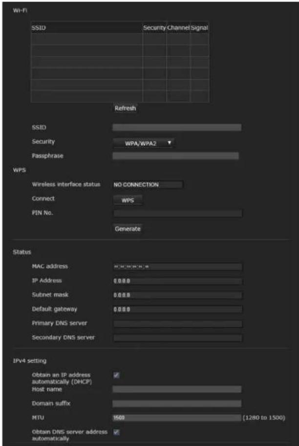
Supported models: SNC-CX600W
Use this tab to set the connection of the Wi-Fi network.
Notes
- A wired network and a Wi-Fi network cannot be used at the same time.
- The IP address of a Wi-Fi network will be assigned only when a wired network is not connected.
Wi-Fi network connection check
Displays the current connection status of a Wi-Fi network.
If the camera is connected to a Wi-Fi router, the display will be highlighted.
SSID
Displays SSID of the Wi-Fi router that can be connected to.
Security
Displays the current setting method as either authentication or encryption.
None
Connect to a Wi-Fi router without encryption.
WEP
Connect to a Wi-Fi router using WEP (Wired Equivalent Privacy).
WPA/WPA2
Connect to a Wi-Fi router by performing an authentication which is compliant to WPA/WPA2 (Wi-Fi Protected Access).
Channel
Displays the wireless channels of a Wi-Fi router that can be connected to.
Signal
Displays the signal strength. If it is lower than 60%, improve the installation environment as follows:
1 Change the installation position of the camera.
2 Adjust the antenna angle of the Wi-Fi router.
3 Change the installation position of the Wi-Fi router.
4 Install a repeater.
Note
The displayed signal intensity is an estimate. If the number is small, the connection may break easily.
Refresh
Refresh the Wi-Fi network display.
Note
When you click Refresh, video or images may be interrupted.
Manual setting of a Wi-Fi network
You can set the connection of a Wi-Fi router manually. Before connecting, locate the Wi-Fi router setting information (SSID, authentication, encryption, key or password, etc.).
Note
The connection may not be possible if you use the router that is not compliant with the Wi-Fi standard (802.11b/g/n).
SSID
This is the identification for the Wi-Fi network connection.
Security
Select authentication and encryption to combine with a Wi-Fi network connection.
Note
Communication contents may be intercepted depending on the security setting.
WPA/WPA2
Connect to the Wi-Fi network using WPA/WPA2 authentication. It is necessary to enter a Passphrase.
WEP (Deprecated)
Type a WEP key (encryption key) of alphanumeric characters.
Communication contents may be intercepted because the security of WEP is weak. This setting is not recommended.
None (Deprecated)
Connect to the Wi-Fi network without encryption. Communication contents may be intercepted from an unencrypted connection. This setting is not recommended.
WPS settings
Set WPS (Wi-Fi Protected Setup).
WPS is the standard of Wi-Fi Alliance to simply connect to a Wi-Fi network with security protection. Before connecting to the Wi-Fi network, check whether the Wi-Fi router is compliant with the WPS standard.
Click the WPS push button, or enter the 8-character PIN code for the Wi-Fi router.
Wi-Fi network connection by WPS button
1 Refer the instruction manual of the Wi-Fi router, and enable the WPS function (button method).
2 Click WPS. Check the status whether it is Connecting.
3 The automatic setting between the Wi-Fi router and the camera starts. It takes up to two minutes to connect.
4 When the connection is complete, the status will be Connected.
The status Connection failure. means the connection was not performed successfully. Check whether the WPS function of the Wi-Fi router is enabled. For details, refer to the instruction manual of the Wi-Fi router. If you still cannot connect, use “Manual setting of the Wi-Fi network.”
5 An IP address for a Wi-Fi network will be assigned when the network cable of the camera is disconnected.
Wi-Fi network connection by PIN code
1 Click Generate to generate the PIN code.
2 Enter the 8-character PIN code generated by step 1 to connect to the Wi-Fi router. For details on how to enter or connect, refer the instruction manual of the Wi-Fi router.
3 Click Connect to start the connection by PIN method. It takes up to two minutes to connect to WPS.
4 When the connection is complete, the status will be Connected.
The status Connection failure. means the connection was not performed successfully. Check whether the WPS function of the Wi-Fi router is enabled. For details, refer to the instruction manual of the Wi-Fi router. If you still cannot connect, use “Manual setting of the Wi-Fi network.”
5 An IP address for a Wi-Fi network will be assigned when the network cable of the camera is disconnected.
Connection status
Displays the setting status.
MAC address
Displays the MAC address of the camera.
IP address
Displays the current IP address.
Subnet mask
Displays the current subnet mask.
Default gateway
Displays the current default gateway.
Primary DNS server
Displays the current primary DNS server.
Secondary DNS server
Displays the current secondary DNS server.
IPv4 setting
Configure the IPv4 network setting.
To obtain the IP address automatically from a DHCP server
Select Obtain an IP address automatically (DHCP).
The IP address, subnet mask, default gateway are assigned automatically.
Note
When you select Obtain an IP address automatically (DHCP), make sure that a DHCP server is operating on the network.
To specify the IP address manually
Deselect Obtain an IP address automatically (DHCP). Type the address in the IP address, Subnet mask and Default gateway boxes. Host name and Domain suffix are not available.
IP address
Type the IP address of the camera.
Subnet mask
Type the subnet mask.
Default gateway
Type the default gateway.
Host name
Type the host name of the camera to be transmitted to the DHCP server. This setting is valid only when Obtain an IP address automatically (DHCP) is selected.
Domain suffix
Type the domain suffix of the camera to be transmitted to the DHCP server. This setting is valid only when Obtain an IP address automatically (DHCP) is selected.
Note
The domain suffix is sent to the DHCP server as FQDN (Fully Qualified Domain Name) information when Host name is set.
MTU
Type the IP-MTU value for the Ethernet port.
To obtain DNS server address automatically
Select Obtain DNS server address automatically. The Primary DNS server and Secondary DNS server are assigned automatically.
Note
To obtain a DNS server address automatically, first enable Obtain an IP address automatically (DHCP) in the IPv4 setting.
Ask the network administrator whether a DNS server address can be obtained automatically.
To specify the DNS server address manually
Deselect Obtain DNS server address automatically. Type the address in the Primary DNS server and Secondary DNS server boxes.
Primary DNS server
Type the IP address of the primary DNS server.
Secondary DNS server
Type the IP address of the secondary DNS server, if necessary.
OK/Cancel
See "Buttons common to every menu" on page 23.
QoS Tab

In this tab, you can mark the data traffic packets sent from the device and configure the settings for QoS control. Rules for the types of data traffic can be created using IPv4 address, port number, protocol, etc. A maximum of 10 rules can be registered.
IPv4 QoS
Enable
Select the checkbox to configure the QoS setting for IPv4.
Rule
Used to register, edit and delete QoS.
No.
Select the number to use when registering on the QoS table.
When you select a registered number, the registered QoS information is displayed.
Network address
Enter the network address of the target on which to perform QoS.
Subnet
Enter the subnet mask values of the target on which to perform QoS.
Tip
The subnet mask value represents the number of bits from the left side of the network address.
Protocol
Select the protocol.
Port
Enter the port number for the data traffic of the device (e.g. HTTP:80).
DSCP
Set a value to mark the data traffic (0 \~ 63).
This value is set in the DSCP field included in the IP header of the data traffic.
Set
Used when registering on the QoS table.
QoS is set according to the following procedure:
1 Select No. from No. and enter the necessary conditions for Network address, Subnet, Protocol and/or Port No..
2 Enter values in DSCP.
3 Click Set and configure the QoS.
Delete
Select No. to delete the setting and click Delete.
Move up
Increases the priority of the rule. Select a rule from the QoS table to prioritize and click Move Up.
Move Down
Decreases the priority of the rule. Select a rule from the QoS table to lower its priority and click Move Down.
QoS table
Displays the list of registered QoS information. If multiple conditions match, the rule with the smallest number has priority.
OK/Cancel
See "Buttons common to every menu" on page 23.
UPnP Tab
Set UPnP (Universal Plug and Play).
Discovery
Enable
If the UPnP discovery function is enabled, you can search the camera by using UPnP.
If you want to disable this function, deselect the checkbox for the UPnP discovery function.
OK/Cancel
See "Buttons common to every menu" on page 23.
Setting the Security
— Security Menu
When you click Security administrator menu, the Security menu appears.
The Security menu consists of the User, Access limit, SSL, 802.1X and Referer check tabs.
User Tab
Set the user names and passwords of Administrator and up to 9 types of user (User 1 to User 9), and the viewer mode of each user.
Administrator, User 1 to 9
Specify User name, Password, Re-type password and Viewer mode for each user ID.
User name
Type a user name between 5 and 16 characters.
Password
Type a password between 5 and 28 characters.
To enhance security, we strongly recommend you set a password with 8 to 28 characters including both numbers and letters.
Re-type password
To confirm the password, retype the password that you typed in the Password box.
Audio
Set whether to enable the audio output to the speaker connected to the line output jack of the camera or the built-in speaker. If you need to output the audio, select the checkbox to enable.
Note
Be sure to set Audio upload in the Audio tab of the Video / Audio menu to Enable.
Playback
Set whether to enable using the playback viewer. Select the checkbox to enable.
Viewer mode
When the user is authenticated for logging in the viewer, select the viewer mode to be displayed after authentication.
Administrator: The user can operate all functions in this mode.
Full: The user can operate all functions except deleting the recorded movie in the memory card.
Pan/Tilt: In addition to the Light mode, the user can operate pan/tilt/zoom.
Light: In addition to the View mode, the user can select the image size of the viewer, select codec and capture a still image.
View: The user can only monitor the camera image.
For the functions available for each viewer mode, see "Administrator and User" on page 12.
Viewer authentication
Set whether the user is authenticated or not when the viewer is displayed.
When the checkbox is selected, the viewer is displayed in accordance with the viewer mode of the authenticated user. When the checkbox is not selected, select the viewer mode of the viewer which is displayed without authentication from Full, Light or View.
Note
Setting viewer authentication can prevent unintended third parties from viewing the video.
Without setting the viewer authentication, people can view the video without inputting a user ID or password. To prevent unintended third parties from viewing the video, we strongly recommend for you to set viewer authentication and change the password on a regular basis.
Authentication mode
Set the authentication method for user authentication.
Basic authentication: Use the basic access authentication.
Digest authentication: Use the digest access authentication.
Note
If you change the settings in Authentication mode, close the web browser and access again.
OK/Cancel
See “Buttons common to every menu” on page 23.
Access limit Tab

This allows you to control which computers can have access to the camera.
Likewise, when using IPv6, security settings can be configured for each network.
Enable
Select the checkbox to enable the access limit.
Default policy
Select the basic policy of the limit from Allow and Deny for the computers specified in the Network address/Subnet 1 to Network address/Subnet 10 menus below.
Network address/Subnet 1 to Network address/Subnet 10
Type the network addresses and subnet mask values that you want to allow or deny access to the camera.
You can specify up to 10 network addresses and subnet mask values. For a subnet mask, type 8 to 32.
(In the case of IPv6, enter a value between 8 and 128.)
Select Allow or Deny from the drop-down list on the right for each network address/subnet mask.
Tip
The subnet mask value represents the bit number from the left of the network address.
For example, the subnet mask value for "255.255.255.0" is 24.
If you set 192.168.0.0/24 and Allow, you can allow access from computers having an IP address between "192.168.0.0" and "192.168.0.255".
Note
You can access the camera even from a computer having an IP address whose access right is set to Deny, if you enter the user name and password set for the
Administrator boxes in the User menu.
OK/Cancel
See "Buttons common to every menu" on page 23.
SSL Tab

Configure the SSL or TLS function (called "SSL" hereafter). The settings allow the camera to communicate with the client PC by using SSL.
Notes
- The model on sale in China does not support the SSL function.
- When using the SSL function, always configure the settings after setting the date and time of the camera. If the date and time are not correctly set, it may cause browser connection problems.
- Reload the window when you change the SSL setting. Press the F5 key on the keyboard to reload.
Common setting
SSL function
Select Enable to use the SSL function.
When Enable (Allow HTTP connection for some clients) is selected, both HTTP and SSL connections are allowed. When Enable is selected, only SSL connection is allowed.
When Internet Explorer is used
When SSL session is established, appears in the right of the address bar on your web browser.
When you use SSL connection for the first time
When you use SSL connection only with the SSL function Enable, you cannot access the camera if the SSL function does not work properly. In this case, you must reset the camera to the factory settings. (All settings will be initialized.) To avoid this, check that SSL connection is possible by performing the following steps.
1 Set the SSL function to Enable (Allow HTTP connection for some clients).
2 Click OK to close the viewer and the setting window.
3 Display the viewer in SSL connection.
Refer to “Using the SSL function” on page 8 for connection.
4 After confirming that SSL connection is possible, set the SSL function to Enable.
Even if the setting window or the browser is closed as SSL connection is impossible, http connection will be possible if Enable (Allow HTTP connection for some clients) is selected. First check the setting contents of SSL tab in http connection, then check the SSL connection again.
If Enable (Allow HTTP connection for some clients) is not selected, you will not be able to access the camera if SSL connection becomes impossible. In this case, turn on the power of the main unit while pressing the reset switch on the camera to initialize. For details, refer to the supplied Installation Manual.
Note
SSL connection will load the camera down; therefore, not all images may be downloaded, and the mark may appear when the camera accesses the setting
window from the browser. In this case, reload the window. Press the F5 key on the keyboard to reload.
SSL server authentication
Certificate options
Select an installation mode of the certificate.
Use an external certificate: Uses the certificate including private key information issued by a CA. The PKCS#12 and PEM formats are supported.
Note
SSL is not available when Certificate options-Use an external certificate is selected, or certificate and private key password is not set properly even SSL is set to "Enable".
Use a self-signed certificate (For test use): This mode uses the certificate and private key pair generated by "Self-signed certificate generation" on page 48. Private key information corresponding to the certificate is stored in the camera. You do not need to install an external certificate. However, you cannot execute the existence proof that is one of the SSL functions for the following reasons. - The private key generated in the camera is self-signed by the camera. - A prepared value is set for a distinguished name (Common name, etc). - The certificate is not issued by a trusted CA. For reasons of security, we recommend using this mode only when there is no problem even if perfect security is not saved.
Notes
- When Use a self-signed certificate (For test use) is selected, the Security Alert dialog appears on the SSL connection with a browser.
For details, refer to "Using the SSL function" (page 8). - SSL connection may be impossible due to the type of certificate installed in the camera. In this case, refer to “How to install the CA certificate” on page 49 and install.
To import the certificate
Click Browse... to select the certificate to be imported. Click the OK button appearing on the dialog when you select the file, to import it to the camera.
Note
The import process becomes invalid if the selected file is not a certificate or the imported certificate is not allowed.
Self-signed certificate generation
A self-signed certificate can be generated in the camera to be used when Use a self-signed certificate (For test use) is selected from Certificate options.
Click Generate to generate a self-signed certificate in the camera. Clicking Generate again after Generate has been clicked once will update the self-signed certificate stored in the camera.
Note
Make sure to set the date and time on the camera correctly before performing this operation. If the date and time are not correctly set, it may cause browser connection problems. Before selecting Generate in Self-signed certificate generation, click OK to select Use a self-signed certificate (For test use) in Certificate options.
To display certificate information
When the certificate has been set in the camera correctly, its information appears on Status, Issuer DN, Subject DN, Validity Period and Extended Key Usage.
Status
Shows if the status of the certificate is valid or invalid. The following statuses are recognised.
Valid: The certificate is correctly stored and set.
Invalid: The certificate is not correctly stored and set. Possible causes are as follows:
- Use an external certificate is selected and the private key password included in the certificate is not specified correctly.
- Use an external certificate is selected and the private key password is specified in spite of the fact that the key pair in the certificate is not encrypted.
- Use an external certificate is selected and the key pair is not included in the certificate.
- Use a self-signed certificate (For test use) is selected without the self-signed certificate being generated.
Note
When the certificate to be imported is of PKCS#12 format and the private key password is not set correctly,
Specify the correct private key password to confirm the information of the certificate.
To delete the imported certificate or self-signed certificate
Click Delete to delete the certificate or self-signed certificate imported to the camera.
Private key password
Type the password for the private key information included in the certificate using up to 50 characters. This text box is active only when Certificate options is set to Use an external certificate.
Leave the text box blank if the private key information included in the certificate is not encrypted.
If no private key password is set in the camera, an active text field is displayed and this allows a password to be entered.
If a private key password is already set, it is displayed as an inactive text field.
Reset
To change the private key password, click this button. The current password is cleared and the password text box becomes active to allow a new password entry.
Note
Click Cancel at the bottom of the menu if you want to cancel changing the private key password after clicking Reset. Doing so restores the other setting items in the Client certificate tab to the previous settings.
SSL client authentication
In this tab, you can manage the CA certificate needed for the camera to use the client authentication of the SSL function.
Notes
- When you use client authentication, the personal certificate must be imported to your PC properly. For details, see “To import the personal certificate” on page 51.
If this preparation cannot be performed, do not configure settings on this tab. Otherwise, you may not be able to connect to the camera. - The setting of SSL client authentication is available only when SSL server authentication certificates are uploaded.
Enable
You can configure whether to enable the client authentication of the SSL function.
Trusted CA certificate 1 to 4
You can import a trusted CA certificate (route certificate, etc.) to the camera.
Up to four certificates from trusted CAs can be imported to the camera. Only PEM format is supported.
To import the CA certificate
1 Click Browse... to select the CA certificate to be saved in the camera.
2 Click the OK button appearing on the dialog. The selected file will be imported to the camera.
Note
Import process will be invalid if the selected file is not a CA certificate.
To display the information of the CA certificate When the CA certificate has been saved in the camera correctly, its information appears on Issuer DN, Subject DN, Validity Period, and Extended Key Usage for your reference.
To delete the CA certificate
Click Delete to delete the selected CA certificate from the camera.
Tip
To enable a client certificate, it is recommended that the settings are configured following the procedure below:
①Import the necessary CA certificate.
②Select the SSL client authentication checkbox and click OK.
Note
When you set SSL client authentication to Enable and click OK, the camera will immediately operate to enable client authentication. Make sure that the personal certificate is imported to your PC in advance. For details, see “To import the personal certificate” on page 51.
OK/Cancel
See "Buttons common to every menu" on page 23.
How to install the CA certificate
The camera may not be connected because the browser (Internet Explorer) does not display whether the certificate will be accepted or not due to the type of certificate. In this case, install the CA certificate as follows.
1 Save in the PC the certificate of CA which has signed the certificate to be installed in the camera. The extension of the certificate file is normally ".cer". Double-click this file. The following Certificate dialog appears.

2 Click Installation Certificate... The Certificate Import Wizard appears.

3 Click Next.

4 Select Automatically selects the certificate store based on the type of certificate and click Next. Completing the Certificate Import Wizard appears.

5 Check the contents, then click Finish. The CA certificate will be installed.
To remove an installed CA certificate
1 In Internet Explorer, click in the order Tools, Internet options, Content tab and Certificates. The Certificates dialog appears.

2 Select the certificate you want to remove. The CA certificate is usually stored in Trusted Root Certification Authorities.
3 Click Remove. Do you want to delete the certificate appears to confirm.
4 Click Yes. The certificate will be removed. There may be a case that a certificate cannot be removed by the steps above due to the type of certificate. Check the installation condition and remove it following the steps below.
Note
You need to log in as Administrator to perform these steps.
1 Open Run... of the Windows menu, then enter mmc and click OK.
2 Select File in the Console 1 window and Add/Remove Snap-in... (when Windows XP Professional is used). Add/Remove Snap-in... dialog appears.
3 Select Certificates from the list, then click Add. Certificate Snap-in is displayed.
4 Select Computer account as the certificate administrated in this Snap-in, then click Next.
5 Select Local Computer as the computer administrated in this Snap-in, then click Finish.
6 The items for administrating Certificates appears in the Console Route window. Confirm the relevant certificate, then remove it.
To import the personal certificate
To use client authentication, follow the steps below to import the personal certificate.
1 Double click the personal certificate stored in your PC.
2 Certificate Import Wizard is displayed.
3 Start importing by marking Enable this key as exportable during the process.
Display sample: If the OS language is English

802.1X Tab

Configure the wired port-based authentication in compliance with the 802.1X standard.
Notes
- To use the 802.1X authentication function, you need knowledge of the 802.1X authentication and digital certificate. To establish an 802.1X network, you need to configure the authenticator, authentication server and other elements. For details on these settings, refer to the manual of the corresponding equipment.
- When using the 802.1X authentication function, always configure the settings after setting the date and time of the camera. If the date and time are incorrect, port authentication may not be performed correctly.
System configuration of 802.1X network
The following figure shows a general system configuration of an 802.1X network.
![graph LR A["Supplicant (camera)"] --> B["Authenticator (hub or router)"] B --> C["Authentication server + CA"]](/content/2026/08/1615217/images/81830635a4035b17b2ff45d9883bfdda78be5e2da59f21b0153aaf8f7e117982.jpg)
Supplicant
A supplicant is a device that connects to the authentication server to join the network. This camera serves as a supplicant in the 802.1X network. The supplicant can enter the 802.1X network after appropriate authentication by the authentication server.
Authenticator
An authenticator forwards certificate request data or response data that the supplicant or authentication server issues to the other party. Normally a hub, router or access point serves as an authenticator.
Authentication server
An authentication server has a database of connecting users and verifies if the supplicant is a valid user or not. It can also be called RADIUS server.
CA (Certificate Authority)
A CA issues and manages certificates of the authentication server (CA certificates) and user certificates. The CA is essential for certificate-based user authentication. Normally a CA is located inside an authentication server.
Note
This camera supports EAP mode in which the supplicant and the server authenticate using the certificate. This mode requires a CA to issue the certificate.
Common setting
Enable
Select the checkbox to enable the 802.1X authentication function.
EAP identity
Type the user name to identify the client in the 802.1X authentication server up to 250 characters.
EAP password
A supplicant EAP password is needed to be inputted when PEAP is selected with EAP condition. The password can contain half-width letters and the length should be within 50 characters.
Reset
To change the once set EAP password, click Reset and clear the current password. A new password can be entered.
Note
After you click Reset, if you wish to cancel the EAP password change, click Cancel at the bottom of the screen. This will cancel other changes made to the settings.
EAP method
You can select the authentication method used with the authentication server. This device supports TLS and PEAP.
TLS: By this method, the supplicant and the server authenticate each other using a certificate. This enables secure port authentication.
PEAP: By this method, an EAP password is used for the supplicant authentication and a certificate is used for server authentication.
Client certificate
When TLS is selected as the EAP method, the client certificate is imported, displayed or deleted for the camera authentication.
To import the client certificate
Click Browse... to select the client certificate to be imported.
Click the OK button appearing on the dialog, and the selected file will be imported to the camera.
Note
The import process becomes invalid if the selected file is not a client certificate or the imported client certificate is not allowed.
To display the information of the client certificate
When the client certificate has been saved in the camera correctly, its information appears on Status, Issuer DN, Subject DN, Validity Period and Extended Key Usage.
Status
Shows if the status of the client certificate is valid or invalid.
Valid means the client certificate is correctly stored and set.
Invalid means the client certificate is not correctly stored and set.
Possible causes of Invalid are as follows:
- The private key password included in the client certificate is not specified correctly.
- The private key password is specified in spite of the fact that the key pair in the client certificate is not encrypted.
– The key pair is not included in the client certificate.
Note
When the client certificate to be imported is of PKCS#12 format and the private key password is not set correctly, "
To delete the client certificate
Click Delete, and the client certificate stored in the camera will be deleted.
Private key password
Type the password for the private key information included in the client certificate using up to 50 characters. Leave the text box blank if the private key information included in the client certificate is not encrypted. If a private key password is already set, it is displayed as turned letters.
Reset
To change the private key password, click this button. The current password is cleared and the password text box is activated to allow new password entry.
Note
Click Cancel bottom of the screen if you want to cancel changing the private key password after clicking Reset. Doing so restores the other setting items in the Client certificate tab to their previous settings.
CA certificate
You can import a trusted CA certificate (server certificate or route certificate) to the camera. Up to four certificates from trusted CAs can be imported to the camera. Only the PEM format is supported.
To import the CA certificate
Click Browse... to select the CA certificate to be imported. Click the OK button appearing on the dialog, and the selected file will be imported to the camera.
Note
Import process becomes invalid if the selected file is not a CA certificate.
To display the information of the CA certificate
When the CA certificate has been saved in the camera correctly, its information appears on Issuer DN, Subject DN, Validity Period and Extended Key Usage.
To delete the CA certificate
Click Delete, and the CA certificate stored in the camera will be deleted.
OK/Cancel
See "Buttons common to every menu" on page 23.
Referer check tab
Referer check checks if the web page which requires access is authorized when the camera is accessed. If the web page is not authorized, the camera denies access of the web page to the camera.
If you want to access from web pages other than the one that the camera provides, register their host names and port numbers in the Exception list.
Referer check
Select the checkbox for the Referer check.
Exception list
Register the hosts that are not targeted for the Referer check.
No.
Select the registered numbers of the Exception list.
Host name
Type the host name or IP address of the PC that supplies the web page you want to register on the Exception list.
Port No.
Type the host name or the port number of the PC that supplies the web page you want to register on the Exception list.
Set
Register the values of the Host name and Port No. you typed to the list of the selected number.
Delete
Delete the contents of the list selected in No.
OK/Cancel
See "Buttons common to every menu" on page 23.
Setting the PTZ control — PTZ control Menu
When you click PTZ control administrator menu, the PTZ control menu appears.
The PTZ control menu consists of the following tab: View angle
SNC-VB635 displays Serial tab, also.
View angle Tab
Zoom mode
You can select an e-Varifocal mode that has less image quality degradation without using the digital zoom area and the Solid PTZ mode that can shoot images further zooming in. You can set Image 1, Image 2, and Image 3 separately.
Notes
When selecting the e-Varifocal mode
- Select an image size other than the maximum size in the Video codec tab.
Note that for the models
(SNC-VB600/VB600B/VM600/VM600B/VM601/
VM601B/VM602R/EB600/EB600B/EB602R/
EM600/EM601/EM602R) that have a maximum
image size: 1280 × 1024 , select an image size other than the following image sizes.
1280 × 1024, 1280 × 960, 1280 × 720
- Zoom limitation is changed depending on the selected image size.
Home position setting
Set
Set the current position that the viewer displays as the home position.
Reset
Reset the home position to the range of factory settings that are shot in the maximum image size.
Image
Select the images that you want to set the angle of image for in the e-Varifocal mode or the Solid PTZ mode.
1 Select the images that you want to set.
2 Select the images that you want to operate and display.
3 Adjust the shooting range with the control bars (page 18).
Note
The shooting range memorized in the Home position setting is displayed after turning on the power.
OK/Cancel
See "Buttons common to every menu" on page 23.
Serial Tab
Display sample: SNC-VB635

Supported models: SNC-VB635
Set this setting to control other devices connected via RS-485 interface, in which a control signal (TCP/IP packets) from the network is converted into an RS-485 signal. Recommended setting depends on the connected device.
TCP port No.
Set the port number to any number in the range 1024 to 65535, except well-known port numbers.
Baud rate
Set the baud rate corresponding to the connected devices. The available baud rates are as follows. 38400, 19200, 9600, 4800, 2400, 1200(bps)
Parity bit
Select the parity corresponding to the connected devices, from [none], [odd], [even].
Character length
Select the character length corresponding to the connected devices, from [8], [7] (bits).
Stop bits
Select the stop bits corresponding to the connected devices, from [2], [1] (bits).
OK/Cancel
See “Buttons common to every menu” on page 23.
Setting the Sensor input/ Camera tampering detection/Motion detection
— Action input Menu
When you click Action input nistrator menu, the Action input Menu appears.
The Action input Menu consists of the following tabs:
SNC-VB635/VB630/VB600/VB600B/VB632D/VB640/VB642D/VM630/VM600/VM600B/VM631/VM601/VM601B/VM632R/VM602R/VM641/VM642R/XM631: Event condition, Sensor input, Camera tampering detection, Motion detection, Face detection and Network disconnection.
SNC-EB630/EB630B/EB600/EB600B/EB632R/EB602R/EM630/EM600/EM631/EM601/EM632R/EM602R: Event condition, Camera tampering detection, Motion detection and Face detection.
SNC-EB640/EB642R/EM641/EM642R/XM637/XM636/XM632/CX600W/CX600: Event condition, Camera tampering detection, Motion detection, Face detection and Network disconnection.
When the Motion detection or Face detection tab is displayed for the first time
When you click Motion detection or Face detection, "Security Warning" is displayed. When you click Yes, ActiveX control is installed and the Motion detection or Face detection tab is displayed.
Notes
- If Automatic configuration is enabled in the Local Area Network (LAN) settings of Internet Explorer, the image may not be displayed. In that case, disable Automatic configuration and set the proxy server manually. For the setting of the proxy server, consult your network administrator.
- When you install ActiveX control, you should be logged in to the computer as Administrator.
Event condition Tab
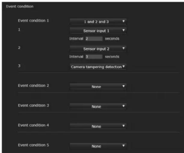
Create event execute conditions for each action.
Event condition 1, 2, 3, 4, 5
Select the event condition.
You can combine the alarm using the following event execute conditions.
and: detect when both conditions happen within a specified interval regardless of the sequence.
or: detect when either condition happens.
then: detect when each of the conditions happen within a specified interval in sequence.
If you set the event condition to None, the following alarm 1, 2, 3 menus appear.
1, 2, 3
Select the alarm.
Selectable alarms are as follows.
Displayed items vary depending on the function.
Sensor input 1: The external sensor that is connected to sensor input 1 of the camera I/O port.
Sensor input 2: The external sensor that is connected to sensor input 2 of the camera I/O port.
Presence sensor: The alarm is triggered by the presence sensor function.
Camera tampering detection: The alarm is triggered if the camera detects tampering, such as direction shifting or spray.
Motion detection: The alarm is triggered by the motion detection function.
VMF: The alarm is triggered by the VMF function.
Face detection: The alarm is triggered by the face detection function.
Network disconnection: The alarm is triggered by disconnection to a specific IP address.
Note
You cannot set more than two functions for Presence sensor, Camera tampering detection or Network disconnection in the same event condition.
Interval
Specify the interval time used when condition is set to and, then.
In the case the condition is set as 1 and 2, the system sounds an alarm when either 1 or 2 happens, and the other happens within the specified interval.
In the case the condition is set as 1 then 2, the system sounds an alarm when 1 happens, and then 2 happens within the specified interval.
If you select "or" condition, this setting will be ignored.
The maximum duration to be set is 7200 seconds.
Sensor input Tab — Set the sensor input 1/2

Sensor input mode
Set the direction of the detected input signal to the sensor input terminal of the camera.
Normally open: Triggers an alarm when the sensor input is short-circuited.
Normally closed: Triggers an alarm when the sensor input is open-circuited.
Notes
- Allow at least two seconds for the input signal to be detected; otherwise, some events may not be detected.
- When you use video streaming by SSL connection, set as follows. Some events may not be detected if the camera is not in the following conditions.
- Set the Bit rate below 1 Mbps.
- Set the Frame rate below 30 fps.
– Use the video streaming below two transmissions at the same time.
OK/Cancel
See “Buttons common to every menu” on page 23.
Camera tampering detection Tab — Set the camera tampering detection
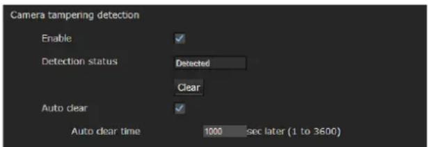
Notes
- Before using the camera tampering detection function, first adjust the focus* or the focus/zoom**. If you adjust focus/zoom with the camera tampering detection function activated, detection may not be effective.
* Focus: SNC-VB635/VB630/VB600/VB600B/VB640/EB630/EB640/EB600
** Focus/zoom: SNC-VB632D/VB642D/VM630/VM600/VM600B/VM631/VM601/VM601B/VM632R/VM602R/VM641/VM642R/EB632R/EB642R/EM630/EM600/EM631/EM601/EM632R/EM602R/EM641/EM642R/EB602R
- Deselect the checkbox of Stabilizer in the Installation tab of the System menu. After setting the camera tampering detection, set the Stabilizer function again.
Enable
Select the checkbox to activate the function to detect camera tampering, such as direction shifting or spray.
Detection status
Display the tampering detection state of the time when Camera tampering detection tab is opened. To clear the detection status, click Clear button.
Auto clear
Clear the detection status automatically.
Select the checkbox to set the time to be cleared automatically. When the checkbox is not selected, the detection status will not be cleared unless the Clear button is pressed.
Auto clear time
Set the time from when the camera tampering detection is detected until the detection status is cleared automatically.
OK/Cancel
See "Buttons common to every menu" on page 23.
Motion detection Tab — Set the motion/VMF detection
Motion detection responds to moving objects in the camera image and triggers an alarm.
In VMF, an alarm sounds when motion is detected under the motion detection setting, entering or passing through a specified area or inspection line. An alarm also sounds when an object has been left or removed from a specified area or inspection line.
The detected object will be displayed on the monitor in the green frame. The removed object and left object will be displayed in the magenta frame.
Note
Perform the following before setting the motion detection.
- Set Image size1 in the Video codec tab of the Video / Audio menu or Video menu to the maximum rate.
- Deselect the checkbox of Image 1 in the PTZ control tab of the PTZ control menu.
- Deselect the checkbox of Stabilizer in the Installation tab of the System menu.
What is VMF
VMF is a function for detecting an object entering or passing through a specified area or inspection line, or when an object has been left or removed from a specified area or inspection line. Video/audio recording and/or audio file playback can be synchronized with this alarm. You can set the inspection methods to execute independently. Intrusion and Passing can also be set to execute in combination.
For example:
- An alarm sounds when an object enters areas A, B and C.
- An alarm sounds when an object passes through area A and enters area B.
- An alarm sounds when an object passes through areas A and B, and enters area C.
- An alarm sounds when an object enters area A, and passes through area B.
Intrusion
When a moving object enters the designated area, an alarm sounds.
Passing
A passage line is determined, and when a moving object passes the setting line, an alarm sounds.
Left object
When a moving object has been left in the designated area, an alarm sounds.
Removed object
When a moving object has been removed from the designated area, an alarm sounds.
Notes
- Before actual use, perform an operation test and confirm that the motion detection function works correctly.
- Even when privacy masking is used, the motion detection function operates based on the images before masking is processed.
Setting items for motion detection
Use the settings tab to set the conditions for the motion detection function while observing camera images.

VMD settings
Detection area
Specify the effective scope of motion detection.

Note
The frames shown on the monitor screen are not displayed on the image files sent or recorded with motion detection.
Configuring the detection area
The following procedure is used to configure the motion detection area:
1 Use the following buttons to specify the active area(s) and inactive area(s).

Add detection area
Clicking this button will add an active area window in the center of the screen.
When you place the cursor on the area, the cursor changes to a crossed arrow, which you can drag to move the area.
When you place the cursor on the vertex of the area, the cursor changes to ↔ , which you can drag to move the vertex.

Add non detection area
Clicking this button will add an inactive area window in the center of the screen.
When you place the cursor on the area, the cursor changes to a crossed arrow, which you can drag to move the area.
When you place the cursor on the vertex of the area, the cursor changes to ↔ , which you can drag to move the vertex.

Delete Area
Clicking this button will change the cursor to a button. While the cursor is a button, click on a part of the area to delete that area.
After the deletion, the cursor will return to its original form. To exit this operation, click this button again.
It is the same function as the button displayed under VMF settings.

Add vertex
Clicking this button will change the cursor to a button. In that state, when you click on a part of the side of the area, a vertex is added to that point. After the addition, the cursor will return its original form.
To exit this operation, click this button again.
It is the same function as the button displayed in VMF settings.

Delete vertex
Clicking this button will change the cursor to a button. In that state, when you click on a part of the vertex of the area, the vertex added to that point is deleted. After the deletion, the cursor will return its original form. To exit this operation, click this button again.
It is the same function as the button displayed in VMF settings.
Note
The vertex can be moved in an outward direction but cannot be moved toward the inside of an area.
Detection sensitivity
Set the sensitivity of motion detection.

A value from 1 to 256 can be specified.
Clicking Return to the default changes the value to the default value.
Detection response
Set the response velocity of motion detection.

A value from 1 to 5 can be specified.
Clicking Return to the default changes the value to the default value.
Detection size
Specify the minimum detection size and maximum detection size for motion detection. To specify the detection size, you can either enter values or drag the vertexes of the area.
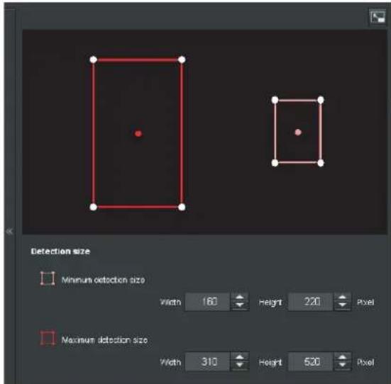
The area size is measured in pixels.
- When you place the cursor on the area, the cursor changes to a crossed arrow, which you can drag to move to the minimum detection size area and maximum detection size area.
- When you place the cursor on the vertex of the area, the cursor changes to ↔ . Drag and move the vertex to adjust the detection size.
Moving shadow exemption
Set ON/OFF for the moving shadow exemption function of motion detection.
Selecting Do not respond to shadows will prevent the shadows of a moving object from being recognized as moving objects.
Deselect the checkbox to disable the shadow removal function of motion detection.
VMF settings
Set the alarm to sound when the specified conditions (Intrusion, Passing, Left object, Removed object) of the motion detection occur. You can also set the order for Intrusion or Passing, and set the alarm to sound only when the specified conditions occur in sequence.
Filter type
Select the filter type from Intrusion, Passing, Left object, Removed object or Off.
Time until left/removed object is detected
Enter the time you want to elapse before the alarm is triggered. This setting is available only when the filter type is set to Left object or Removed object.
Filter settings
Settings for each filter can be edited here.
The inspection line and active window are set to default values. Edit according to use.
■ VMF status indicator of each filter
The filter is on when the set filter type conditions (Intrusion, Passing, Left object, Removed object) are met.
Tip
The buttons displayed on the edit screen for filter is used in the same way as those for detection setting. See page 58.
Intrusion

This criterion is for whether a moving object exists in the trigger area.
Similar to an active window, a trigger area can also be moved and vertexes can be moved, added or deleted.
Passing

Edit the pass inspection line according to the following procedure:
Passing object trigger line
By default, one passing object trigger line is displayed. The number of vertexes is 2.
Placing the cursor on the line will turn the cursor into a cross, and when you drag the line, the whole line will move.
Placing the cursor on the vertex will turn the cursor into ↔ , and when you drag the line, the vertex will move. The arrow displayed in the center of the passing object trigger line shows the direction of inspection. Trigger is performed when an object passes the passing object trigger position in this direction.
Trigger direction setting
Each time you click the trigger direction toggles among the directions left, right and both.
Passing object trigger position
Select the passing object trigger position from All sides, Left side, Top side, Right side and Bottom side.
Left object

This criterion is for whether a moving object has been left in the trigger area.
Similar to an active window, a trigger area can also be moved and vertexes can be moved, added or deleted.
Removed object

This criterion is for whether a moving object has been removed from the trigger area.
Similar to an active window, a trigger area can also be moved and vertexes can be moved, added or deleted.
Trigger size
Specify the minimum trigger size and maximum trigger size of motion. To specify the size, you can either enter values or drag the vertexes of the area.
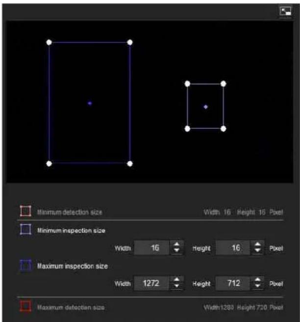
The size of motion is measured in pixels.
- When you place the cursor on the area, the cursor changes to a crossed arrow, which you can drag to move the minimum trigger size area and maximum trigger size area.
- Placing the cursor on the vertex of the minimum trigger size area or maximum trigger size area will change the cursor to , then you can drag the vertex to change the inspection size.
Tip
The minimum and maximum detection sizes configured in the VMD setting are displayed, but the size of the area cannot be modified from here.
Trigger speed
Specify the minimum and maximum speeds to be detected.

- Min. speed and Max. speed can be specified within a scale of 100.
- The blue marker for minimum speed cannot be set to the right of the red marker for maximum speed.
• The squares indicating Min. speed and Max. speed move on the right and left sides of the preview screen.
Note
The set value is only valid under the conditions of Intrusion or Passing.
Matching decision
Select the filter type you want to match and check Use as matching condition.
Select Filter 1, Filter 2 and Filter 3 in the list box of Matching decision.
Set the alarm to sound when the specified maximum 3 conditions occur in sequence. If the conditions occur in a different order, the alarm will not sound. Select the condition from Intrusion, Passing or None.
Filter order switching button
Clicking switches the order of filter between the neighbouring methods.
e.g., If you click the button between 1 and 2, they will switch order. If you click the button between 2 and 3, they will switch order.
Specifying the time
Specify the reference interval in seconds between 1 and 2, or 2 and 3.
For example, if 1 and 2 are set and “3 seconds” is specified, an alarm will sound when the inspection conditions of 2 are met within 3 seconds from when the inspection conditions of 1 are met.
■ VMF status indicator of Matching decision
The indicator is on when the set filter type conditions are met.
Full-screen display button
Click to display the ActiveX area in full screen. Clicking again will show the normal display.
Stretch bar
Click hide the menu list on the left and enlarge the preview screen.
Clicking again will show the menu list as it was before.
OK/Cancel
Click OK to finalize any changes made to the settings and send them to the camera.
If you click Cancel, changes made to the settings will be discarded and the screen will be reloaded with the current camera settings.
Face detection Tab — Set the face detection

Face detection responds to faces in the camera image and triggers an alarm.
Notes
- Before actual use, perform an operation test and confirm that the face detection function works correctly.
- Perform the following before setting the face detection.
-
S eImage size1 in the Video codec tab of the Video / Audio menu or Video menu to the maximum rate.
-
Deselect the checkbox of Image 1 in the PTZ control tab of the PTZ control menu.
- Deselect the checkbox of Stabilizer in the Installation tab of the System menu.
- Some parts at the top and bottom cannot be set for models which have a maximum image size of 1280 × 1024 (SNC-VB600/VB600B/VM600/VM600B/VM601/VM601B).
- An inactive area cannot be specified.
- A horizontal face (leaning too far sideways) cannot be detected.
- Vertexes cannot be added or deleted. They are for specifying a rectangular area only.
- Even when privacy masking is used, the face detection function operates based on the images before masking is processed.
Detection area
Specify the effective scope of face detection. You can set the area in the same way as the detection area setting in VMD settings. (page 58)
A maximum of ten detection areas can be set. Similar to the detection area setting in VMD settings, a trigger area and vertexes can also be moved.
Detection sensitivity
Set the sensitivity of face detection. A value from 0 to 64 can be specified. Select low values to limit detection to the human face, or high values to also detect subjects that are similar the human face. This makes detection easier when the subject is far from the camera.
Clicking Return to the default changes the value to the default value.
Detection size
Specify the minimum and maximum size of face detection. You can specify the size by specifying values or by dragging vertexes to choose the area.
OK/Cancel
Click OK to finalize any changes made to the settings and send them to the camera.
If you click Cancel, changes made to the settings will be discarded and the screen will be reloaded with the current camera settings.
Network disconnection Tab — Monitoring the connection of a specified IP address

Monitored IP address
Set the specific IP address of which the network connection status is to be monitored.
OK/Cancel
See “Buttons common to every menu” on page 23.
Setting the Action output — Action output Menu
When you click Action output nistrator
menu, the Action output menu appears.
The Action output Menu consists of the following tabs:
SNC-VB635/VB630/VB600/VB600B/VB640/VM630/VM600/VM600B/VM631/VM601/VM601B/VM632R/VM641/VM642R/VM602R: Execution Condition, Mail Transfer, Edge Storage, Alarm output, Voice alert, HTTP alarm notification and FTP still image sending.
SNC-EB630/EB630B/EB600/EB600B/EB632R/EB602R/EM630/EM600/EM631/EM601/EM632R/EM602R: Execution Condition, Mail Transfer, HTTP alarm notification and FTP still image sending.
SNC-XM637/XM636/XM632: Execution Condition, Mail Transfer, Edge Storage, HTTP alarm notification and FTP still image sending.
SNC-XM631: Execution Condition, Mail Transfer, Alarm output, Edge Storage, HTTP alarm notification and FTP still image sending.
SNC-CX600W/CX600: Execution Condition, Mail Transfer, Edge Storage, Voice alert, White LED, HTTP alarm notification and FTP still image sending.
SNC-VB632D/VB642D: Execution Condition, Mail Transfer, Alarm output, Edge Storage, Voice alert, White LED, HTTP alarm notification and FTP still image sending.
SNC-EB640/EB642R/EM641/EM642R: Execution Condition, Mail transfer, Edge Storage, Voice alert, HTTP alarm notification and FTP still image sending.
Execution Condition Tab
Set execute conditions for each action.
Set the action output execute conditions when the condition created in the Event condition tab is implemented.
Displayed items vary depending on the function.
Mail Transfer: Set the condition of mail transfer.
Alarm output 1: Set the condition to control alarm output of the I/O port on the rear of the camera.
Alarm output 2: Set the condition to control alarm output of the I/O port on the rear of the camera.
Edge Storage movie: Set the condition to record movies using the Edge Storage function.
Edge Storage still image: Set the condition to record still images using the Edge Storage function.
Voice alert 1: Set the condition of Voice alert 1 recorded in the camera.
Voice alert 2: Set the condition of Voice alert 2 recorded in the camera.
Voice alert 3: Set the condition of Voice alert 3 recorded in the camera.
HTTP alarm notification 1: Set the condition for the HTTP alarm notification to recipient 1.
HTTP alarm notification 2: Set the condition for the HTTP alarm notification to recipient 2.
HTTP alarm notification 3: Set the condition for the HTTP alarm notification to recipient 3.
FTP still image sending: Set the condition for sending with the FTP still image sending function.
White LED: Set the White LED lighting condition. Only the Presence Sensor (SNC-CX600W/CX600) and the Motion detection (SNC-VB632D/VB642D) can be selected. The White LED lights up when it is dark.
Mail Transfer Tab — Setting the e-Mail (SMTP) Function
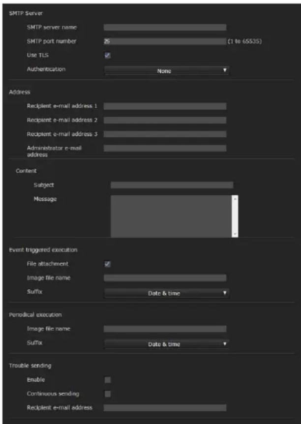
SMTP Server
Notes
- You cannot send an audio file by using the e-mail sending function.
- The frame rate and operability on the viewer may be reduced while a file is being transmitted by the e-Mail (SMTP) function.
SMTP server name
Type the SMTP server name using up to 64 characters, or the IP address of the SMTP server.
SMTP port number
Enter a port number from 1 to 65535.
The standard port number is 25.
The standard port number of SMTPs is 465, if the TLS function is enabled.
Use TLS
When using the encryption function of the TLS, select the checkbox.
Note
Models sold in China do not support the TLS function.
Authentication
Select whether authentication is required when you send an e-mail.
None: No authentication is required when an e-mail is sent.
SMTP: Select when SMTP authentication is required.
POP before SMTP: Select when POP before SMTP authentication is required.
Combination of POP before SMTP and SMTP: Select when both SMTP authentication and POP before SMTP authentication is required.
POP mode
Select POP3 or APOP as the authentication method for POP authentication.
Note
The model on sale in China does not support the APOP authentication.
Wait time after POP
Set the waiting time in POP before SMTP before SMTP authentication after POP authentication is completed. Timeout can be set from 0 to 10,000 msec.
POP server name
This is necessary when POP before SMTP is selected for Authentication.
Type the POP (receiving mail) server name using up to 64 characters, or type the IP address of the POP server. This setting is necessary when the SMTP server that sends e-mails performs authentication using the POP user account.
POP port number
Enter a port number from 1 to 65535.
The standard port number is 110.
POPs standard port number is 995, when the TLS is enabled.
Authentication mode
Select Login or CRAM-MD5 as the authentication method for SMTP authentication.
Note
The model on sale in China does not support the CRAM-MD5 authentication.
User name, Password
Type the user name and password of the user who owns the mail account using up to 64 characters. This setting is necessary when the SMTP server that sends e-mails performs authentication.
Address
Recipient e-mail address 1, 2, 3
Type the recipient e-mail address using up to 64 characters.
You can specify up to three recipient e-mail addresses.
Administrator e-mail address
Type the Administrator e-mail address using up to 64 characters.
This address is used for reply e-mails and sending system messages from the mail server.
Content
Subject
Type the subject/title of the e-mail. The length for entering letters should be within 64 characters. When an e-mail is sent in response to an alarm detection, the following string that indicates the type of alarm that will be added in the subject.
- When the Sensor 1 detects an alarm: (Sensor 1)
- When the Sensor 2 detects an alarm: (Sensor 2)
- When the Presence Sensor detects an alarm: (Presence Sensor)
- When the Camera tampering detection detects an alarm: (Tampering)
-
When the Motion detection detects an alarm: (VMD)
-
When VMF detects an alarm: (VMF)
- When the Network disconnection is detected (Disconnected)
- When the Face detection detects an alarm: (Face Detection)
(Event1 (Condition1)) is additionally available for event condition detection.
Message
Type the text of the e-mail.
The length for entering letters should be within 384 characters.
Event triggered execution
File attachment
Set whether an image file (JPEG file) is to be attached to the e-mail or not.
When the checkbox is selected, the image file made using the settings below is attached. When the checkbox is deselected, only the message is sent.
When the Image rotate in the Installation tab of the System menu is set to 90 degrees or 270 degrees, the attached image file becomes an image that does not rotate.
Image file name
Type the file name you want to assign to the image to be attached to an e-mail. You can use up to 10 alphanumeric characters, – (hyphen) and _ (underscore) for naming.
The actual image file name will be the specified image file name with a suffix and the extension .jpg.
Suffix
Select a suffix to be added to the file name used when the e-mail is sent.
None: The name of the sent file will be the image file name.
Date & time: The date & time suffix is added to the image file name.
The date & time suffix consists of last two-digits of the year (2 digits), month (2 digits), date (2 digits), hour (2 digits), minute (2 digits), second (2 digits), and sequential number (2 digits), thus adding 14-digit number to the image file name.
Periodical execution
You can set to send e-mails periodically.
Image file name
Type the file name of the image attached to the e-mail using up to 10 alphanumeric characters, – (hyphen) and – (under score).
The actual image file name will be the specified image file name with a suffix and the extension .jpg.
Suffix
Select a suffix to be added to the file name used when the e-mail is sent.
None: The name of the sent file will be the image file name.
Date & time: The date & time suffix is added to the image file name.
The date & time suffix consists of last two-digits the year (2 digits), month (2 digits), date (2 digits), hour (2 digits), minutes (2 digits) and seconds (2 digits), and sequential number (2 digits), thus adding a 14-digit number to the image file name.
Trouble sending
Supported models: SNC-VB635/VB630/VB600/VB600B/VB632D/VB640/VB642D/VM630/VM600/VM600B/VM631/VM601/VM601B/VM632R/VM602R/VM641/VM642R/EB640/EB642R/EM632R/EM602R/EM641/EM642R/XM637/XM636/XM632/XM631/CX600W/CX600
Set to send an e-mail if a problem with a built-in fan or memory card has been found.
Enable
Select the checkbox to enable the sending of problem reports.
Continuous sending
Set whether to enable continuous e-mail sending. When the checkbox is selected, an e-mail will be sent once an hour.
Recipient e-mail address
Type the recipient's e-mail address within 64 characters.
OK/Cancel
See “Buttons common to every menu” on page 23.
Alarm output Tab — Setting the Alarm output
You can perform setting in this menu to control the alarm output of the I/O port on the rear of the camera linked to alarm detection function.
Tip
For details on connection of peripheral devices to the alarm output of the I/O port, refer to the supplied Installation Manual.
Duration
Duration 1, 2
Enter the duration for which the alarm is output, between 1 sec. and 60 sec.
Memory card trouble detection
Set to output the alarm when trouble of the memory card is detected.
Output port 1, 2
Check the I/O port number that outputs the alarm when the trouble of memory card is detected.
OK/Cancel
See “Buttons common to every menu” on page 23.
Edge Storage Tab — Setting the Edge Storage movie and still image function

With Edge Storage, video or audio signal can be recorded from the alarm detection results, such as network block, recorded video and audio can be streamed with the same protocol as the real-time streaming.
Notes
- The frame rate and operability on the main viewer may be reduced during movie or still image recording.
- The actual interval of recording a still image may be longer than the interval you set.
- Stop the Edge Storage recording before you turn off the power of the camera with a memory card inserted.
- Before you remove or insert a memory card, stop the Edge Storage recording and turn off the power of the camera.
- Before using a memory card, format it by Format memory card in the Initialize tab of the System menu (page 26).
- A maximum of 4000 movie records can be saved to a memory card. If the checkbox of Overwrite is not selected when the number of records reaches 4000, new recordings cannot be made. If the checkbox of
Overwrite is selected when the number of records reaches 4000, the unit will begin to overwrite old records in ascending chronological order.
• Overwrite is not available for a memory card of less than 4 GB.
- When recording H.264, the recorded data may become very large and the video/audio may be interrupted if the Adaptive rate control is set and other image codec except CBR is selected. Therefore, selecting CBR is recommended.
If you select CBR, set the video codec as follows:
- Set t Bit rate below 2000 kbps.
- Set t Frame rate below 30 fps.
- Set the picture interval to 1 second.
- When you record the JPEG with image size 1280 × 720 or above, set the video codec as follows:
– SNC-VB635/VB630/VB632D/VB640/VB642D/VM630/VM631/VM601/VM632R/VM641/VM642R/EB640/EB642R/EM641/EM642R/XM637/XM636/XM632/XM631: Set the Image quality below 2.
- SNC-VB600/VB600B/VM600/VM600B/VM601B/VM602R/CX600W/CX600: Set the Image quality below 5.
- Set t Frame rate to 1 fps.
- When you record, set the Image codec 2 and Image codec 3 of the Video codec tab in the Video / Audio menu to Off.
Common setting
Memory card
Display the available free space of external memory.
Maintenance information
Displays the status of the memory card if you are using the memory card that corresponds to displaying Maintenance information.
Overwrite
Select On to overwrite the file when there is insufficient memory space.
When you select the checkbox, overwrite is enabled. Old records will be overwritten in chronological order. When you deselect the checkbox, overwrite is prohibited, and no recording will be performed.
Note
Records are overwritten in chronological order, regardless of whether they are movies or still images.
Edge Storage still image
Recording data
You can refer to still image files recorded in the memory card. These files will be saved in a folder tree as follows./sdcard/EdgeStoragePicture/00000000-999999999/00000000-99999999/
(Prefix)YYYYMMDDhhmmss00000001.jpg
Path: Displays the path name of the recording still image file.
When you select a file, a still image will be displayed.
Delete: Click Delete to delete the selected folder or file. If you select a folder, any files in the folder will also be deleted.
Refresh: Click Refresh to reload the latest data.
Recording target
Select the video codec mode you want to record.
For detailed settings of video codec mode, see the Video codec tab in the Video / Audio menu.
Notes
- You can record still images even if the video is specified with an image codec set to H.264.
- Image quality setting for a still image can be changed only when the image codec is set to JPEG.
- If you want to change the image quality of recorded still images, change the image codec to JPEG.
- A folder containing no still image files may appear.
- When the Image rotate in the Installation tab of the System menu is set to 90 degrees or 270 degrees, the still image becomes an image that does not rotate.
Image file name
The file name consists of three parts: a prefix, a file number and an extension.
Set the prefix of up to 30 alphanumeric characters. You can include - (hyphen) and _ (underscore) in the prefix. The file number and extension are assigned automatically by the camera.
The file number consists of the year (4 digits), month (2 digits), date (2 digits), hour (2 digits), minutes (2 digits), seconds (2 digits), and a sequential number (8 digits).
The Greenwich Mean Time will be used in the file name. The extension is .jpg.
Edge Storage movie
Recording status
Display the current recording status.
The recording status will not be updated until the screen is refreshed.
Use the Start Recording and Stop Recording button to start or stop the recording manually.
Note
When recording manually, do not set Edge Storage movie in the Execution Condition tab of the Action output menu to Off.
Recording target
Video: Select the video codec mode you want to record. For detailed settings of video codec mode, see the Video codec tab in the Video / Audio menu.
Audio: Set whether to record the audio signals input from the camera. Select the checkbox to record.
Note
Set Audio sending (page 33) in the Audio tab of the Video / Audio menu to Enable.
Recording capacity
Displays the maximum recording time in the current camera setting of the video mode, image size, bit rate and frame rate.
Pre-alarm period: Displays the maximum recording time before the alarm is triggered.
Post-alarm period: Displays the maximum recording time after the alarm is triggered.
Note
Maximum recording time varies depending on the image size and quality setting in the Video / Audio menu.
Recording time
Set the recording time for the Pre-alarm image/audio and Post alarm image/audio.
Pre-alarm period: Type the recording time of the image/audio before alarm detection.
Post-alarm period: Type the recording time of the image/audio after alarm detection.
OK/Cancel
See "Buttons common to every menu" on page 23.
Voice alert Tab
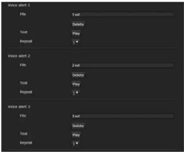
Set the voice alert function to output audio from the speaker connected to the line output jack of the camera or the build-in speaker of the camera when an alarm is triggered by the sensor input or detection functions.
Note
Before using the voice alert function, you need to save the audio file to the camera using the SNC toolbox. You can download SNC toolbox and application guides from the download site.
Voice alert 1, 2, 3
Up to three voice alerts can be set. Configure the following setting for each voice.
File
Displays the name of the audio file saved in the camera. "Not uploaded" is displayed dimly if no audio file is saved.
To delete the audio file saved in the camera, click
Delete.
Note
Before deleting an audio file, set Voice alert to Off. Voice alert is included in the Execution Condition tab of the Action output menu.
Test
When an audio file is saved in the camera, you can check it by playing it back.
Click Play to play back the audio file.
Repeat
Select playback repeat time from 1 to 3.
Notes
- If voice alert is actively linked with a different alarm type while another voice alert is occurring, the first voice alert is cancelled and the second one is output.
- When you play back a test, do not set Voice alert in the Execution Condition tab of the Action output menu to Off.
- If two or three audio files are set to be output simultaneously linked with the same alarm type, priority is given in the order Voice alert 1, 2 then 3.
OK/Cancel
See "Buttons common to every menu" on page 23.
HTTP alarm notification Tab
Set to notify a specified URL of an alarm when an event is detected.
HTTP alarm notification 1, 2, 3
Set up to 3 recipients who you want to notify of the alarm.
User name
Type the user name for authentication using up to 64 characters.
Password
Type the password for authentication using up to 64 characters.
Notification at the beginning of event detection Select the checkbox for the alarm notification when the event detection starts.
URL
Type the recipient of the alarm.
Test
If you click Execute, the alarm will be notified manually regardless of whether an event is detected.
Notification at the end of event detection
Select the checkbox for the alarm notification when the event detection ends.
Note
If the VMF, Camera tampering detection, Face detection, Event condition are set as conditions for executing HTTP alarm notification, the Notification at the end of event detection cannot be set.
URL
Type the recipient of the alarm.
Test
If you click Execute, the alarm will be notified manually regardless of whether an event is detected.
Use Proxy
Select the check box if you use a proxy server.
Address
Type the address of the proxy server using up to 255 characters.
Port No.
Type the port number of the proxy server using up to 255 characters.
User name
Type the user name for proxy server authentication using up to 64 characters.
Password
Type the password for proxy server authentication using up to 64 characters.
OK/Cancel
See "Buttons common to every menu" on page 23.
FTP still image sending Tab
Set the items for the still file images that are recorded at alarm detection or recorded periodically and sent to the FTP server.
Notes
- While transferring the files with FTP still image sending, the frame rate and operability of the main viewer decrease.
- When the Image rotate in the Installation tab of the System menu is set to 90 degrees or 270 degrees, the still image becomes an image that does not rotate.
FTP server
Set the items for the FTP server where files will be sent.
Server name
Type the FTP server name of the FTP server where you want to upload the files using up to 64 characters or type the IP address of the FTP server.
User name
Type the user name for the FTP server using up to 64 characters.
Password
Type the password for the FTP server using up to 64 characters.
Passive mode
Set whether to use the passive mode of the FTP server when you connect to the FTP sever. If you select the checkbox, you can connect to FTP sever in passive mode.
Alarm sending
Image to be sent
Select the video codec mode for the image of alarm sending.
Set the details of the video codec mode in the Video / Audio menu or the Video codec tab in the Video menu.
Remote path
Type the path where the files will be sent using up to 64 characters.
Image file name
Type the file name of the image that you want to send to the FTP server using up to 10 alphanumeric characters, - (hyphen) and _ (underscore).
Suffix
Select a suffix to be added to the file name used when the image is sent.
Date & time: The date & time suffix is added to the image file name. The date & time suffix consists of last two-digits of the year (2 digits), month (2 digits), date (2 digits), hour (2 digits), minute (2 digits), second (2 digits), and sequential number (2 digits), thus adding 14-digit number to the image file name.
Sequence number: A sequential 10-digit number 0000000001-4294967295 and a sequential 2-digit number are added to the image file name to be sent.
Sequence number clear
If you click Clear, the suffix of the Sequence number returns 1.
Test
If you click Execute, the image will be sent to the FTP server once for testing according to the settings of alarm sending.
Periodical sending
Image to be sent
Select the video codec mode of the image of periodical sending.
Set the details of the video codec mode in the Video / Audio menu or the Video codec tab in the Video menu.
Remote path
Type the path where the files will be sent using up to 64 characters.
Image file name
Type the file name of the image that you want to send to the FTP server using up to 10 alphanumeric characters, - (hyphen) and _ (underscore).
Suffix
Select a suffix to be added to the file name used when the image is sent.
None: The name of the sent file will be the image file name.
Date & time: The date & time suffix is added to the image file name.
The date & time suffix consists of last two-digits of the year (2 digits), month (2 digits), date (2 digits), hour (2 digits), minute (2 digits), second (2 digits), and sequential number (2 digits), thus adding 14-digit number to the image file name.
Sequence number: A sequential 10-digit number 0000000001-4294967295 and a sequential 2-digit number are added to the image file name to be sent.
Sequence number clear
If you click Clear, the suffix of the Sequence number returns 1.
Test
If you click Execute, the image will be sent to the FTP server once for testing according to the settings of periodical sending.
Manual sending
Image to be sent
Select the video codec mode of the image of manual sending.
Set the details of the video codec mode in the Video / Audio menu or the Video codec tab in Video menu.
Remote path
Type the path where the files will be sent using up to 64 characters.
Image file name
Type the file name of the image that you want to send to the FTP server using up to 10 alphanumeric characters, - (hyphen) and _ (underscore).
Suffix
Select a suffix to be added to the file name used when the image is sent.
None: The name of the sent file will be the image file name.
Date & time: The date & time suffix is added to the image file name.
The date & time suffix consists of last two-digits of the year (2 digits), month (2 digits), date (2 digits), hour (2 digits), minute (2 digits), second (2 digits), and sequential number (2 digits), thus adding 14-digit number to the image file name.
Sequence number: A sequential 10-digit number 0000000001-4294967295 and a sequential 2-digit number are added to the image file name to be sent.
Sequence number clear
If you click Clear, the suffix of the Sequence number returns 1.
Send
If you click Execute, the image will be sent to the FTP server once for testing according to the settings of manual sending.
OK/Cancel
See "Buttons common to every menu" on page 23.
White LED tab
Display sample: SNC-CX600W

Supported models: SNC-CX600W/CX600
Set the Illuminator level and lighting time of the White LED when the Presence Sensor detects an object.
Display sample: SNC-VB632D
![White LED Perform the following settings when using white LED. -Put [White LED] to [Motion detection] in the [Execution Condition] for [Action output] -Put [Mode] to [Auto] in [Day / Night] for [Video / Audio], and place [Sync with IR Illuminator] to [On] Illuminator level 6▼ Text Execute Stopped Du…](/content/2026/08/1615217/images/92d8cd080b08f465568023a28e9e8682eed8739f5db811b2a831ca40c46691df.jpg)
Supported model: SNC-VB632D/VB642D
Set the Illuminator level and lighting time of the White LED, and the Color or monochrome selectable setting when the Motion detection detects an object.
Illuminator level
Select the White LED Illuminator level from 1 to 6. 1 is the weakest and 6 is the strongest one.
Test
Perform the lighting test of the White LED.
When you press the execute button, the LED lights up with the illuminator level you set. When you press the stop button, the LED turns off.
A message appears if you press the execute button after changing the illuminator level. Click OK if you want to change the illuminator level setting.
Duration
Supported models: SNC-CX600W/CX600
Select the White LED lighting time from 5 seconds to 30 minutes.
Supported model: SNC-VB632D/VB642D
Select the White LED lighting time from 20 seconds to 30 minutes.
Tips
- The lighting time will be extended if the Presence Sensor continues to detect an object. (SNC-CX600W/CX600)
- The lighting time will be extended if the Motion detection continues to detect an object. (SNC-VB632D/VB642D)
Color or monochrome selectable
Supported model: SNC-VB632D/VB642D
You can select Monochrome/Color from Color or monochrome selectable for the illumination color.
OK/Cancel
See "Buttons common to every menu" on page 23.
Notes
Supported model: SNC-VB632D/VB642D
When the White LED is synchronized with the motion detection function:
- Set White LED in the Execution Condition tab of the Action output menu to Motion detection.
- Set Mode in the Day/Night tab of the Video / Audio menu to Auto, and set Sync with IR Illuminator to On.
- When the White LED lights by synchronizing with the motion detection function, it has the following limitations:
– the accuracy of motion detection (VMD) may be low depending on the angle of the image and the VMD settings.
– false or missed detections may occur under the following conditions:
– bad weather, at night or near an object that emits light
– fast-moving objects such as a car
- when the difference of brightness between a moving object and the background is small
- when moving objects approach from the front of the camera slowly
- The camera automatically switches to its built-in optical filter in sync with the White LED. The automatic switching may occur frequently depending on the mounting location and the performance of the optical filter may be affected. Therefore, set the appropriate VMD settings when using the camera.
Setting the Schedule — Schedule Menu
When you click Schedule administrator menu, the Schedule menu appears.
The Schedule menu consists of the Schedule tab.
Schedule Tab
When you click the Schedule tab, the setting menu for each action is displayed.
You can set the schedule of the following actions:
SNC-VB635/VB630/VB600/VB600B/VB640/VM630/VM600/VM600B/VM631/VM601/VM601B/VM632R/VM641/VM642R/VM602R: Mail Transfer (Event), Mail Transfer (Periodical), Alarm output (Event), Alarm output (Timer), Edge Storage movie, Edge Storage still image (Event), Edge Storage still image (Periodical), Day/Night, Voice alert, HTTP alarm notification, FTP still image sending (Event) and FTP still image sending (Periodical).
SNC-VB632D/VB642D: Mail Transfer (Event), Mail Transfer (Periodical), Alarm output (Event), Alarm output (Timer), Edge Storage movie, Edge Storage still image (Event), Edge Storage still image (Periodical), Day/Night, Voice alert, White LED, HTTP alarm notification, FTP still image sending (Event) and FTP still image sending (Periodical).
SNC-EB630/EB630B/EB600/EB600B/EB632R/EB602R/EM630/EM600/EM631/EM601/EM632R/EM602R: Mail Transfer (Event), Mail Transfer (Periodical), Day/Night, HTTP alarm notification, FTP still image sending (Event) and FTP still image sending (Periodical).
SNC-XM637/XM636/XM632: Mail Transfer (Event), Mail Transfer (Periodical), Edge Storage movie, Edge Storage still image (Event), Edge Storage still image (Periodical), Day/Night, HTTP alarm notification, FTP still image sending (Event) and FTP still image sending (Periodical).
SNC-VM602R/XM631: Mail Transfer (Event), Mail Transfer (Periodical), Alarm output (Event), Alarm output (Timer), Edge Storage movie, Edge Storage still image (Event), Edge Storage still image (Periodical), Day/Night, HTTP alarm notification, FTP still image sending (Event) and FTP still image sending (Periodical).
SNC-EB640/EB642R/EM641/EM642R: Mail Transfer (Event), Mail Transfer (Periodical), Edge Storage movie, Edge Storage still image (Event), Edge Storage still image (Periodical), Day/Night, Voice alert, HTTP alarm notification, FTP still image sending (Event) and FTP still image sending (Periodical).
SNC-CX600W/CX600: Mail Transfer (Event), Mail Transfer (Periodical), Edge Storage movie, Edge Storage still image (Event), Edge Storage still image (Periodical), Voice alert, White LED, HTTP alarm notification, FTP still image sending (Event) and FTP still image sending (Periodical).
Action
Displays an action name to set the schedule.
Always
Select the checkbox to always enable the specified condition for each action.
Always is not available for Day/Night.
Interval
You can set the interval of the action which is set to execute periodically.
Setting the schedule
You can set the schedule by arranging the schedule area of each action. Click on the area you want to set the schedule; 1 block for 1 hour. When you double-click on a selected area, the dialog of setting the start time and duration appears, and you can set the details.
If you want to delete a schedule you have set, select the schedule and press the delete key on your keyboard.
Note
When the execution condition of Mail Transfer is set to Periodical, the interval can be set from 30 minutes to 24 hours.
OK/Cancel
See "Buttons common to every menu" on page 23.
Others
Glossary
ActiveX control
A component program object that can be used with web pages or other application programs. The technology for creating ActiveX control is part of software developed by Microsoft.
Bandwidth control
To limit the amount of transmitted data.
Bit rate
The rate at which data bits are transmitted.
Capture
To send audio and video converted to digital data from video devices to a computer.
CBR
CBR stands for Constant Bit Rate control. When you select this setting, bits will be consumed at a constant rate.
Codec
Software/hardware for coding/decoding video and audio data.
Contrast
The difference in tone between the lightest and darkest portions of the image.
Default gateway
Device that can be used to access another network.
DHCP server
Acronym for Dynamic Host Configuration Protocol server. The IP address of a terminal without an individual IP address can be automatically distributed by the Dynamic Host Configuration Protocol (DHCP). The DHCP server assigns the IP addresses to the terminals.
Digital certificate
An electronic certificate that a CA (Certificate Authority) attests that a public key to cancel a secret code is issued by an authentic publisher.
DNS server
Acronym for Domain Name System server. As an IP address required for connecting to the device on an IP network is numerical and difficult to remember, the Domain Name System was established. A domain name is alphabetic and is easier to remember. When a client computer uses a domain name to connect to another computer, it asks a DNS server to translate the name into the corresponding IP address. The client computer can then obtain the IP address of the computer to be connected.
e-Varifocal
Zooming in/out function of an image by enlarging with a software without using an optical zooming function. The image quality degradation is less than the Solid PTZ because it does not use the digital zoom area.
Frame rate
The number of frames of a moving image that can be transmitted per a second.
HTTP port
A port used to communicate between the web server and the web client, such as a web browser.
H.264
An image compression format. The standard written by the JVT (Joint Video Team) a joint organization for standardization (composed of ISO and ITU-T), is capable of transmitting video data at a higher compression rate than that of MPEG4.
IP address
Acronym for Internet Protocol Address. An individual IP address is basically assigned to each piece of equipment connected to the Internet.
JPEG
Acronym for Joint Photographic Expert Group. The still image compression technology or standards of ISO (International Organization for Standardization) and ITU-T. Popularly used as an image compression format on the Internet, etc.
MAC address
A network address that uniquely identifies each LAN card.
Multicast
The class D IP address assigned between 224.0.0.0 and 239.255.255.255. Using this IP address enables you to transmit the same data to multiple equipment.
Network address
The portion that identifies the local network (subnet) in an IP address.
Network bandwidth
Bit rate that can be used for networking.
NTP server
Network time server that transmits and receives time information over the networks.
Primary DNS server
One of the DNS servers that can first reply to a request by connected devices or other DNS servers.
Proxy server
A server or software that acts as an intermediary between a local network and the Internet so that it can connect to the Internet in place of a computer on a local network.
QoS
QoS stands for Quality of Service. A technology for controlling communication priority to improve network stability.
Saturation
The degree to which a color is pure.
Secondary DNS server
Subsidiary DNS server used when a primary DNS server cannot be used.
Sharpness
The degree to which the boundary of two portions is clearly distinguished.
SMTP Server
A server for sending or relaying e-mail messages between servers.
Solid PTZ
Zooming in/out function of an image without using an optical zooming function.
SSL
Acronym for Secure Sockets Layer. This is a protocol developed by Netscape Communications Corporation to be used for communications of encrypted data on the Internet.
Subnet mask
32-bit stream used to distinguish the subnet address from an IP address.
TCP
Acronym for Transmission Control Protocol. A standard protocol used for Internet connection. Compared with the other protocol, UDP, TCP provides reliable communication but communication speed is slower.
UDP
Acronym for User Datagram Protocol. A standard protocol used for Internet connection. Compared with the other protocol, TCP, UDP can transmit data faster, but reliable communication is not guaranteed.
Unicast
Transmission of data to specified equipment on a network by specifying a single address.
VBR
VBR stands for Variable Bit Rate control. When you select this setting, the bit rate will be adjusted to suit the camera scene.
WEP
WEP stands for Wired Equivalent Privacy. It is encryption, compliant with the IEEE802.11 standard.
WPA
WPA stands for Wi-Fi Protected Access. It is a standard for encryption developed by Wi-Fi Alliance, the trade group of wireless LAN.
This encryption function compensates for WEP (Wired Equivalent Privacy) flaws.
WPA2
WPA2 stands for Wi-Fi Protected Access 2. It is a standard for encryption developed by Wi-Fi Alliance, the trade group of wireless LAN.
This encryption function has more strength than WPA.
Index
Numerics
802.1X Tab.... 51
A
Access limit Tab.... 46
Access log Tab 27
access rights 12
Action....74
Action input Menu 55
Action output Menu 64
ActiveX control.... 8,75
ActiveX viewer 13, 14
Address 65
Administrator 12
Administrator e-mail address...... 65
Administrator menu 23
Administrator, User 1 to 9.....45
Alarm output Tab 67
Alignment 35
Always 74
Area zoom mode.... 17
Audio sending 33
Audio Tab.... 33
Audio upload.... 34
Authentication....65
Auto clear....57
Auto clear time....57
Auto iris responding speed ..... 25
B
Background color.... 34
Backup setting data.... 27
Bandwidth control....75
Baud rate 55
Bit rate.... 75
C
CA certificate 53
Camera control panel 15
Camera operating mode 30
Camera tampering detection Tab ... 57
Cancel button 23
Capture.... 15,75
CBR 75
Channel 41
Character length.... 55
Clear.... 36
Clear all.... 36
Client certificate.... 52
Codec 75
Color 36
Color or monochrome selectable ... 72
Common setting ..... 40, 47, 52, 68
Connection status 42
Content......65
Contrast....75
Control bar 16
Control panel.... 14, 17, 20
Control panel (Basic) 21
Control panel (Detail) 21
Current date & time 24
Custom string 34
D
Date & time format 24
Date & time Tab.... 24
Day/Night 35
Day/Night Tab.... 35
daylight saving time.... 25
Default gateway 43,75
Default policy.... 46
Delete superimpose logo.... 27
Delete voice alert file 27
Detection area 63
Detection sensitivity.... 63
Detection size....63
Detection status.... 57
DHCP server 75
Digital certificate.... 75
Discovery 44
DNS server....75
Duration 67,72
E
Easy Focus 31
Event condition Tab 56
Event triggered execution 66
Events displayed 35
Execution Condition Tab...... 64
Exposure....29
F
Face detection Tab.... 62
Factory default 26
File 69
File attachment.... 66
Filter settings....60
Filter type ....59
Focus 31
Focus / Zoom Tab.... 31
Focus refresh 27
Focus reset.... 31
Focus Tab 31
Font size 35
Format memory card.... 26
Frame rate 14,32,75
Full-screen display button.... 62
G
Glossary 75
Greenwich Mean Time.... 25
H
H.264....75
High framerate mode ....32
Home position setting 54
HTTP port 75
|
Image.... 34,54
Image 1, Image 2 and Image 3..... 32
Image codec 14
Image file name.... 68
Image rotate.... 26
Image size 32
Information panel.... 14
Information Tab....24
Initialize Tab.... 26
Installation Tab....25
Internet Explorer 9
Interval 74
Intrusion 57
IP address 13,42,75
IPv4 QoS.... 44
IPv4 setting 39, 43
IPv6 setting 40


J
JPEG....75
L
Language....14
Left object ....57
License notice....14
Live viewer....14
Logging in ....11, 13
M
MAC address....42, 75
Mail Transfer Tab....64
Main menu ....14
Manual....27
Manual time zone....25
Matching decision ......62
Memory card 68
Mic volume 33
Mirroring....26
mode of operation ....15
Model Name....24
Monitor image....16, 22
Monitor screen ....16
Monitored IP address ......63
Motion detection Tab ....57
Multicast....75
Multicast streaming....37
N
Network address....76
Network address/Subnet......46
Network bandwidth....76
Network disconnection Tab......63
Network Menu....39
Network Tab....39
NTP server....76
0
OK button....23
Overwrite....68
P
Pan/Tilt 15, 17, 18
Parity bit ....55
Passing....57
Password....45, 65
PC clock 24
Periodical execution ......66
Picture 30
Picture mode....29
Picture Tab....29
Playback viewer ....14, 20
Plug-in free viewer .....13, 16
POP server name ......65
Position....34, 36
Primary DNS server ....43, 76
Privacy masking Tab 36
Private key password....53
Proxy server....76
PTZ Control bar ....17
PTZ control Menu ....54
Q
QoS....76
QoS Tab....43
R
Reboot 26
Recipient e-mail address ......65
Recording capacity....69
Recording data....68
Recording status ....69
Recording target 68
Recording time ....69
Refresh 41
Removed object....58
Reset....54
Restore setting 27
Re-type password ....45
RTSP setting....38
s
Saturation 76
Schedule 27
Schedule Menu....73
Schedule Tab 73
Screen mode ....14
Search panel 20
Search results list....20
Secondary DNS server .....43, 76
Security....41, 42
Security Menu 45
Security Warning....8, 55
Sensor input mode....56
Sensor input Tab....56
Serial number 24
Serial Tab....55
Service Tab 28
Set....54
Setting....14, 23
Sharpness....76
Signal......41
SMTP Server 65,76
SMTP server name ......65
Software version....24
Solid PTZ 76
Solid PTZ function .....16
SSID 41,42
SSL client authentication......48
SSL server authentication......47
SSL Tab 46
SSL 76
Stabilizer....25
Status 39
Stop bits....55
Streaming Tab....37
Stretch bar....62
Subnet mask 42,76
Superimpose Tab ....34
System log Tab 27
System Menu....24
T
TCP....19,76
TCP port No. 55
Text color....34
Time setting....25
Time zone 25
Transmission Mode ......19
Transparent....35
Trigger size....61
Trigger speed....62
Trouble sending 66
Type 34
U
UDP....76
Unicast....76
Unicast streaming....37
UPnP....44
UPnP Tab....44
Use TLS....65
User 12
User name......45, 65
User Tab....45
V
VBR....76
Vector dragging mode .....17
Video / Audio Menu....28
Video codec Tab 32
Video Menu.... 28
View angle Tab.... 54
View panel 14,20
View size.... 14
Viewer authentication 45
Viewer mode 12,45
VMD settings.... 58
VMF 57
VMF settings.... 59
Voice alert 69
Voice alert Tab 69
Volume 15
W
WEP 76
White balance 30
White LED tab 72
Wide dynamic range (View-DR) ... 29
Wide dynamic range (View-DR) level.... 29
Wi-Fi Tab 41
WPA....76
WPA2....76
WPS settings 42
Z
Zoom.... 15, 17, 31
Zoom mode 54

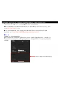
- TABLE OF CONTENTS
- OVERVIEW
- OPERATING THE CAMERA
- ADMINISTRATING THE CAMERA
- SETTING THE ACTION OUTPUT — ACTION OUTPUT
- MENU
- SETTING THE SCHEDULE — SCHEDULE MENU
- OTHERS
- FEATURES
- NOTICE TO USERS
- HOW TO USE THIS USER'S GUIDE
- JUMPING TO A RELATED PAGE
- SOFTWARE DISPLAY EXAMPLES
- PRINTING THE USER'S GUIDE
- INSTALLATION MANUAL (PRINTED MATTER)
- MODEL NAMES
- SYSTEM REQUIREMENTS
- COMMON
- OS
- WEB BROWSER
- CPU
- MEMORY
- DISPLAY
- ACCESSING THE CAMERA USING THE WEB BROWSER
- NOTE
- USING THE SSL FUNCTION
- WHEN INTERNET EXPLORER IS USED
- WHEN "ALLOW HTTP CONNECTION FOR SOME CLIENTS" (PAGE 47) IS CHECKED
- FOR HTTP CONNECTION
- FOR SSL CONNECTION
- WHEN THE LIVE VIEWER OF THE CAMERA IS DISPLAYED FOR THE FIRST TIME
- NOTES
- TIPS
- TO DISPLAY THE VIEWER CORRECTLY
- WHEN USING ANTIVIRUS SOFTWARE, ETC., ON THE COMPUTER
- BASIC CONFIGURATION BY THE ADMINISTRATOR
- PRECAUTIONS FOR PREVENTING ACCESS TO THE CAMERA BY AN UNINTENDED THIRD PARTY
- HOW TO SET UP
- ADMINISTRATOR AND USER
- LOGGING IN TO SYSTEM
- LOGGING IN AS A USER
- ABOUT VIEWERS
- ACTIVEX VIEWER
- WHEN YOU DISPLAY THE VIEWER OF THE CAMERA FOR THE FIRST TIME
- PLUG-IN FREE VIEWER
- CONFIGURATION OF LIVE VIEWER
- MAIN MENU
- LIVE VIEWER
- PLAYBACK VIEWER
- SETTING
- LICENSE NOTICE
- LANGUAGE
- CONTROL PANEL SECTION
- INFORMATION PANEL
- SCREEN MODE
- VIEW SIZE
- IMAGE CODEC
- FRAME RATE
- CAPTURE
- RUN/ STOP SAVE VIDEO
- VOLUME
- MIC VOLUME
- CAMERA CONTROL PANEL
- IMAGE ACTION
- PAN/TILT CONTROL
- ZOOM CONTROL
- OTHER PANEL
- MONITOR IMAGE
- LIVE VIEWER USING PLUG-IN FREE VIEWER
- MONITOR SCREEN
- CONTROL BAR
- USING E-VARIFOCAL AND SOLID PTZ FUNCTIONS
- CONTROLLING VIA THE CONTROL PANEL (OPERATION COMMON TO AREA ZOOM MODE AND VECTOR DRAGGING MODE)
- PANNING AND TILTING BY CLICKING THE MONITOR IMAGE (AREA ZOOM MODE ONLY)
- PANNING, TILTING AND ZOOMING BY SPECIFYING THE AREA (AREA ZOOM MODE ONLY)
- PANNING AND TILTING BY DRAGGING THE SCREEN (VECTOR DRAGGING MODE ONLY)
- USING PAN/TILT/ZOOM OPERATIONS WITH THE DISPLAYED CONTROL BAR (PTZ CONTROL BAR ONLY)
- PAN/TILT OPERATIONS
- ZOOM OPERATION
- SWITCHING TRANSMISSION MODE
- SELECT TCP, UNICAST OR MULTICAST FROM THE CONNECTION DROP-DOWN LIST IN THE OTHER PANEL
- VIEW PANEL
- SEARCH PANEL
- START
- END
- MAXIMUM SEARCH NUMBER
- SEARCH
- SEARCH RESULTS LIST
- RANGE OF THE SEARCH RESULTS DISPLAYED IN THE LIST
- GO TO THE NEXT SEARCH RESULT
- GO TO THE PREVIOUS SEARCH RESULT
- EXPORT SAVE RECORDED MOVIE
- DELETE DELETE RECORDED MOVIE
- CONTROL PANEL (BASIC)
- CONTROL PANEL (DETAIL)
- SPECIFY THE START POSITION FOR PLAYBACK
- TIME
- PREVIOUS RECORD
- STOP BUTTON
- PLAY BUTTON
- PAUSE BUTTON
- FAST FORWARD
- NEXT RECORD
- STILL IMAGE CAPTURE
- SPECIFY THE PLAYBACK TIME
- EXPORT SAVE SELECTED PART OF RECORDED MOVIE
- NOTE ON THE DISPLAY OF MENU OPTIONS
- BASIC OPERATIONS OF THE ADMINISTRATOR MENU
- HOW TO SET UP THE ADMINISTRATOR MENU
- BUTTONS COMMON TO EVERY MENU
- OK
- CANCEL
- GENERAL NOTES ON MENUS
- CONFIGURATION OF THE ADMINISTRATOR MENU
- SYSTEM
- VIDEO / AUDIO
- VIDEO
- NETWORK
- SECURITY
- PTZ CONTROL
- ACTION INPUT
- ACTION OUTPUT
- SCHEDULE
- CONFIGURING THE SYSTEM — SYSTEM MENU
- INFORMATION TAB
- MODEL NAME
- SERIAL NUMBER
- SOFTWARE VERSION
- DATE & TIME TAB
- CURRENT DATE & TIME
- PC CLOCK
- DATE & TIME FORMAT
- TIME SETTING
- NTP SERVER
- TIME ZONE
- MANUAL TIME ZONE
- FORMAT
- AUTOMATICALLY ADJUST CLOCK FOR DAYLIGHT SAVING TIME CHANGES
- OK/CANCEL
- INSTALLATION TAB
- AUTO IRIS RESPONDING SPEED
- STABILIZER
- EFLIP
- IMAGE ROTATE
- MIRRORING
- INITIALIZE TAB
- REBOOT
- FACTORY DEFAULT
- RETAIN CURRENT NETWORK SETTINGS
- TIP
- FORMAT MEMORY CARD
- BACKUP SETTING DATA
- RESTORE SETTING
- RESTORE THE HOME POSITION SETTINGS AND THE PRIVACY MASKING SETTINGS
- FOCUS REFRESH
- MANUAL
- DELETE VOICE ALERT FILE
- DELETE SUPERIMPOSE LOGO
- SYSTEM LOG TAB
- ACCESS LOG TAB
- SERVICE TAB
- SETTING THE CAMERA IMAGE AND AUDIO — VIDEO / AUDIO MENU SETTING THE CAMERA IMAGE — VIDEO MENU
- PICTURE TAB
- PREVIEW SCREEN
- PICTURE MODE
- STANDARD
- SITUATION PRIORITY
- FLICKERLESS
- EXPOSURE
- WIDE DYNAMIC RANGE (VIEW-DR)
- WIDE DYNAMIC RANGE (VIEW-DR) LEVEL
- VISIBILITY ENHANCER
- BACKLIGHT COMPENSATION
- EXPOSURE COMPENSATION
- AUTO GAIN MAX. VALUE
- SHUTTER SPEED
- WHITE BALANCE
- MODE
- PICTURE
- NR (XDNR)
- BRIGHTNESS
- SATURATION
- SHARPNESS
- CONTRAST
- CAMERA OPERATING MODE (SNC-XM637/XM636/XM632/XM631/CX600W/CX600)
- FOCUS TAB — ADJUSTING THE FOCUS
- EASY FOCUS
- FOCUS
- FOCUS RESET
- FOCUS / ZOOM TAB — ADJUSTING THE FOCUS/ZOOM
- ZOOM
- ZOOM POSITION
- VIDEO CODEC TAB
- FULL HD DUAL STREAM MODE
- HIGH FRAMERATE MODE
- IMAGE 1, IMAGE 2 AND IMAGE
- IMAGE SIZE
- I-PICTURE INTERVAL
- H.264 PROFILE
- BIT RATE COMPRESSION MODE
- BIT RATE
- MAXIMUM BIT RATE LIMIT
- MIN, MAX
- IMAGE QUALITY
- BANDWIDTH CONTROL
- AUDIO TAB
- AUDIO SENDING
- ENABLE
- AUDIO IN
- AUDIO CODEC
- AUDIO UPLOAD
- SUPERIMPOSE TAB
- IMAGE
- POSITION
- TYPE
- CUSTOM STRING
- TEXT COLOR
- BACKGROUND COLOR
- ALIGNMENT
- TRANSPARENT
- FONT SIZE
- EVENTS DISPLAYED
- DAY/NIGHT TAB
- SYNC WITH IR ILLUMINATOR
- IR ILLUMINATOR LEVEL
- THRESHOLD
- BRIGHTNESS THRESHOLD
- HOLD TIME
- SENSOR INPUT
- STATUS
- PRIVACY MASKING TAB
- EFFECT
- COLOR
- CLEAR
- CLEAR ALL
- SETTING A PRIVACY MASK
- CLICK OK
- STREAMING TAB
- UNICAST STREAMING
- VIDEO PORT NUMBER
- AUDIO PORT NUMBER
- RTSP VIDEO PORT NUMBER
- RTSP AUDIO PORT NUMBER
- MULTICAST STREAMING
- MULTICAST ADDRESS
- RTSP MULTICAST ADDRESS
- RTSP MULTICAST VIDEO PORT NUMBER
- RTSP MULTICAST AUDIO PORT NUMBER
- RTSP SETTING
- RTSP PORT NO
- RTSP TIME OUT
- CONFIGURING THE NETWORK — NETWORK MENU
- MAC ADDRESS
- ETHERNET STATUS
- AUTO-MDI/MDIX
- IP ADDRESS
- SUBNET MASK
- DEFAULT GATEWAY
- LINKLOCAL IP ADDRESS
- PRIMARY DNS SERVER
- SECONDARY DNS SERVER
- IPV6 ADDRESS
- IPV6 DEFAULT GATEWAY
- LINKLOCAL IPV6 ADDRESS
- IPV4 SETTING
- TO OBTAIN THE IP ADDRESS AUTOMATICALLY FROM A DHCP SERVER
- TO SPECIFY THE IP ADDRESS MANUALLY
- HOST NAME
- DOMAIN SUFFIX
- IPV6 SETTING
- TO OBTAIN THE IPV6 ADDRESS AUTOMATICALLY
- TO SPECIFY THE IPV6 ADDRESS MANUALLY
- PREFIX LENGTH
- COMMON SETTING
- HTTP PORT NUMBER
- MTU
- TO OBTAIN DNS SERVER ADDRESS AUTOMATICALLY
- TO SPECIFY THE DNS SERVER ADDRESS MANUALLY
- WI-FI TAB
- WI-FI NETWORK CONNECTION CHECK
- SSID
- NONE
- WEP
- WPA/WPA
- CHANNEL
- SIGNAL
- REFRESH
- MANUAL SETTING OF A WI-FI NETWORK
- WEP (DEPRECATED)
- NONE (DEPRECATED)
- WPS SETTINGS
- WI-FI NETWORK CONNECTION BY WPS BUTTON
- WI-FI NETWORK CONNECTION BY PIN CODE
- CONNECTION STATUS
- IPV4 QOS
- RULE
- NO
- NETWORK ADDRESS
- SUBNET
- PROTOCOL
- PORT
- DSCP
- SET
- DELETE
- MOVE UP
- MOVE DOWN
- QOS TABLE
- UPNP TAB
- DISCOVERY
- SETTING THE SECURITY
- SECURITY MENU
- USER TAB
- ADMINISTRATOR, USER 1 TO
- USER NAME
- PASSWORD
- RE-TYPE PASSWORD
- AUDIO
- PLAYBACK
- VIEWER MODE
- VIEWER AUTHENTICATION
- AUTHENTICATION MODE
- ACCESS LIMIT TAB
- DEFAULT POLICY
- NETWORK ADDRESS/SUBNET 1 TO NETWORK ADDRESS/SUBNET
- SSL TAB
- SSL FUNCTION
- WHEN YOU USE SSL CONNECTION FOR THE FIRST TIME
- SSL SERVER AUTHENTICATION
- CERTIFICATE OPTIONS
- TO IMPORT THE CERTIFICATE
- SELF-SIGNED CERTIFICATE GENERATION
- TO DISPLAY CERTIFICATE INFORMATION
- TO DELETE THE IMPORTED CERTIFICATE OR SELF-SIGNED CERTIFICATE
- PRIVATE KEY PASSWORD
- RESET
- SSL CLIENT AUTHENTICATION
- TRUSTED CA CERTIFICATE 1 TO
- TO IMPORT THE CA CERTIFICATE
- TO DELETE THE CA CERTIFICATE
- HOW TO INSTALL THE CA CERTIFICATE
- CLICK NEXT
- SELECT AUTOMATICALLY SELECTS THE CERTIFICATE STORE BASED ON THE TYPE OF CERTIFICATE AND CLICK NEXT. COMPLETING THE CERTIFICATE IMPORT WIZARD APPEARS
- CHECK THE CONTENTS, THEN CLICK FINISH. THE CA CERTIFICATE WILL BE INSTALLED
- TO REMOVE AN INSTALLED CA CERTIFICATE
- IN INTERNET EXPLORER, CLICK IN THE ORDER TOOLS, INTERNET OPTIONS, CONTENT TAB AND CERTIFICATES. THE CERTIFICATES DIALOG APPEARS
- SELECT THE CERTIFICATE YOU WANT TO REMOVE. THE CA CERTIFICATE IS USUALLY STORED IN TRUSTED ROOT CERTIFICATION AUTHORITIES
- CLICK REMOVE. DO YOU WANT TO DELETE THE CERTIFICATE APPEARS TO CONFIRM
- CLICK YES. THE CERTIFICATE WILL BE REMOVED. THERE MAY BE A CASE THAT A CERTIFICATE CANNOT BE REMOVED BY THE STEPS ABOVE DUE TO THE TYPE OF CERTIFICATE. CHECK THE INSTALLATION CONDITION AND REMOVE IT FOLLOWING THE STEPS BELOW
- TO IMPORT THE PERSONAL CERTIFICATE
- SYSTEM CONFIGURATION OF 802.1X NETWORK
- SUPPLICANT
- AUTHENTICATOR
- AUTHENTICATION SERVER
- CA (CERTIFICATE AUTHORITY)
- EAP IDENTITY
- EAP PASSWORD
- EAP METHOD
- CLIENT CERTIFICATE
- TO IMPORT THE CLIENT CERTIFICATE
- TO DISPLAY THE INFORMATION OF THE CLIENT CERTIFICATE
- TO DELETE THE CLIENT CERTIFICATE
- CA CERTIFICATE
- TO DISPLAY THE INFORMATION OF THE CA CERTIFICATE
- REFERER CHECK TAB
- REFERER CHECK
- EXCEPTION LIST
- PORT NO
- SETTING THE PTZ CONTROL — PTZ CONTROL MENU
- VIEW ANGLE TAB
- ZOOM MODE
- HOME POSITION SETTING
- SERIAL TAB
- SUPPORTED MODELS: SNC-VB
- TCP PORT NO
- BAUD RATE
- PARITY BIT
- CHARACTER LENGTH
- STOP BITS
- SETTING THE SENSOR INPUT/ CAMERA TAMPERING DETECTION/MOTION DETECTION
- ACTION INPUT MENU
- WHEN THE MOTION DETECTION OR FACE DETECTION TAB IS DISPLAYED FOR THE FIRST TIME
- EVENT CONDITION TAB
- EVENT CONDITION
- INTERVAL
- SENSOR INPUT TAB — SET THE SENSOR INPUT
- SENSOR INPUT MODE
- CAMERA TAMPERING DETECTION TAB — SET THE CAMERA TAMPERING DETECTION
- DETECTION STATUS
- AUTO CLEAR
- AUTO CLEAR TIME
- MOTION DETECTION TAB — SET THE MOTION/VMF DETECTION
- WHAT IS VMF
- INTRUSION
- PASSING
- LEFT OBJECT
- REMOVED OBJECT
- SETTING ITEMS FOR MOTION DETECTION
- VMD SETTINGS
- DETECTION AREA
- CONFIGURING THE DETECTION AREA
- ADD DETECTION AREA
- ADD NON DETECTION AREA
- DELETE AREA
- ADD VERTEX
- DELETE VERTEX
- DETECTION SENSITIVITY
- DETECTION RESPONSE
- DETECTION SIZE
- MOVING SHADOW EXEMPTION
- VMF SETTINGS
- FILTER TYPE
- TIME UNTIL LEFT/REMOVED OBJECT IS DETECTED
- FILTER SETTINGS
- VMF STATUS INDICATOR OF EACH FILTER
- PASSING OBJECT TRIGGER LINE
- TRIGGER DIRECTION SETTING
- PASSING OBJECT TRIGGER POSITION
- TRIGGER SIZE
- TRIGGER SPEED
- MATCHING DECISION
- FILTER ORDER SWITCHING BUTTON
- SPECIFYING THE TIME
- VMF STATUS INDICATOR OF MATCHING DECISION
- FULL-SCREEN DISPLAY BUTTON
- STRETCH BAR
- FACE DETECTION TAB — SET THE FACE DETECTION
- NETWORK DISCONNECTION TAB — MONITORING THE CONNECTION OF A SPECIFIED IP ADDRESS
- MONITORED IP ADDRESS
- SETTING THE ACTION OUTPUT — ACTION OUTPUT MENU
- EXECUTION CONDITION TAB
- MAIL TRANSFER TAB — SETTING THE E-MAIL (SMTP) FUNCTION
- SMTP SERVER
- SMTP SERVER NAME
- SMTP PORT NUMBER
- USE TLS
- AUTHENTICATION
- POP MODE
- WAIT TIME AFTER POP
- POP SERVER NAME
- POP PORT NUMBER
- USER NAME, PASSWORD
- ADDRESS
- RECIPIENT E-MAIL ADDRESS
- ADMINISTRATOR E-MAIL ADDRESS
- CONTENT
- SUBJECT
- MESSAGE
- EVENT TRIGGERED EXECUTION
- FILE ATTACHMENT
- IMAGE FILE NAME
- SUFFIX
- PERIODICAL EXECUTION
- TROUBLE SENDING
- CONTINUOUS SENDING
- ALARM OUTPUT TAB — SETTING THE ALARM OUTPUT
- DURATION
- MEMORY CARD TROUBLE DETECTION
- OUTPUT PORT
- EDGE STORAGE TAB — SETTING THE EDGE STORAGE MOVIE AND STILL IMAGE FUNCTION
- MEMORY CARD
- MAINTENANCE INFORMATION
- OVERWRITE
- EDGE STORAGE STILL IMAGE
- RECORDING DATA
- RECORDING TARGET
- EDGE STORAGE MOVIE
- RECORDING STATUS
- RECORDING CAPACITY
- RECORDING TIME
- VOICE ALERT TAB
- VOICE ALERT
- FILE
- TEST
- REPEAT
- HTTP ALARM NOTIFICATION TAB
- HTTP ALARM NOTIFICATION
- URL
- NOTIFICATION AT THE END OF EVENT DETECTION
- USE PROXY
- FTP STILL IMAGE SENDING TAB
- FTP SERVER
- SERVER NAME
- PASSIVE MODE
- ALARM SENDING
- IMAGE TO BE SENT
- REMOTE PATH
- SEQUENCE NUMBER CLEAR
- PERIODICAL SENDING
- MANUAL SENDING
- SEND
- WHITE LED TAB
- ILLUMINATOR LEVEL
- COLOR OR MONOCHROME SELECTABLE
- SCHEDULE TAB
- ACTION
- ALWAYS
- SETTING THE SCHEDULE
- GLOSSARY
- ACTIVEX CONTROL
- CBR
- CODEC
- DHCP SERVER
- DIGITAL CERTIFICATE
- DNS SERVER
- E-VARIFOCAL
- HTTP PORT
- H
- JPEG
- MULTICAST
- NETWORK BANDWIDTH
- PROXY SERVER
- QOS
- SOLID PTZ
- SSL
- TCP
- UDP
- UNICAST
- VBR
- WPA
- INDEX
- NUMERICS
- A
- B
- C
- D
- E
- F
- G
- J
- L
- M
- N
- P
- Q
- R
- S
- T
- U
- V
- W
- Z
Brand : SONY
Model : SNC-VM631
Category : Surveillance Camera