
DWAMV - Electronic pressure switch HONEYWELL - Free user manual and instructions
Find the device manual for free DWAMV HONEYWELL in PDF.

| Product type | Electronic pressure switch / Pressure controller |
| Brand | HONEYWELL |
| Model | DWAMV |
| Category | Maximum pressure limiter |
| Max. switching voltage | 250 V DC |
| Max. switching current | 8 (5) A |
| Ambient temperature | -20 to 70 °C |
| Max. agent temperature | 70 °C |
| Protection class | IP 54 |
| Housing material | Die-cast aluminum |
| Pressure connection | G 1/2 external (manometer connection) |
| Mounting position | Vertical or horizontal |
| Main functions | Maximum pressure monitoring, adjustable switching, limiter with mechanical lock (optional) |
| Safety | Do not open the device, do not readjust lacquered screws, observe electrical and hydraulic limits |
| Maintenance | Protect from solar radiation and rain; avoid condensation |
| Adjustment | Two concentric pins: large for switching point, small inner screw for differential |
| Switching differential | Adjustable (DWAMV model) |
| Contact type | Microswitch (bistable for SDBAM limiter) |
| Certifications | TÜV, according to TRD 604, DIN 4751, directive 97/23/EC |
| Precautions | Risk of burns if high temperature; use RC circuits for inductive loads |
| Important note | Precision device factory-set, do not modify lacquered screws |
Frequently Asked Questions - DWAMV HONEYWELL
User questions about DWAMV HONEYWELL
0 question about this device. Answer the ones you know or ask your own.
Ask a new question about this device
Download the instructions for your Electronic pressure switch in PDF format for free! Find your manual DWAMV - HONEYWELL and take your electronic device back in hand. On this page are published all the documents necessary for the use of your device. DWAMV by HONEYWELL.
USER MANUAL DWAMV HONEYWELL
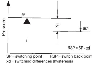
$$ R S P = S P - x d $$
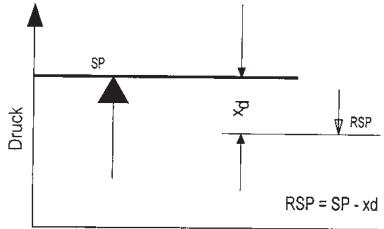
xd = Schaltdifferenz (Hysterese)
Pressure monitor Pressure limiter (with internal or external interlock)
Action direction
For maximum pressure monitoring
Installations acc. to TRD 604
Installations acc. to DIN 4751, P.2
Sensor
"Special design" by sensor with safety function
Testing basis for type test according PED 97/23EC
VdTUV-Publication Pressure 100/1 and DIN 3398, Part 4
Certificate No.
01 202 931-B-02-0005-01 for DWAM...
01 202 931-B-02-0006-01 for DWAMV...
01 202 931-B-02-0007-01 for SDBAM...
Important note:
The pressure switches are precision devices which are set and adjusted in the factory. Therefore do not open the device, do not change the adjustment of the varnished adjustment screws. The switching points would change - readjustment would be necessary.
TÜV
Installation and commissioning
- Pressure switches may only be installed by personnel trained in this application area (electric/hydraulic/mechanical) in accordance with the installation instructions and local legal requirements.
- The devices must only be installed (mechanical, pressure-side connection) on electrochemically matched materials, otherwise there is risk of damage to base metals through contact corrosion which can result in loss of stability and leakage.
- Caution when touching device - risk of burns. Device can reach a medium temperature of up to 70^ . Risk of freezing when working with media up to -20^ .
Safety instructions
-
Devices in the DWAM, DWAMV and SDBAM series are designed for use as pressure monitors and limiters for steam and hot water, and for process engineering applications in which self-monitoring functionality is necessary in order to comply with safety requirements.
-
The device must only be used within the electric, hydraulic and thermal limits specified in the data sheet.
- Inductive loads can cause contact burns or fuse the contacts. Preventative measures must be implemented by the customer, e.g. through use of suitable RC elements.
- When using the version with ZF 1979 (oil and grease-free), take care to avoid recontamination of surfaces that are in contact with media, right through from opening the packaging to completed installation. Generally, no liability will be assumed for oil and grease-free version.
- High quality stainless-steel sensor parts in contact with media enable the devices to be used with a variety of media. However, a chemical resistance test MUST be carried out before selection.
- Use with acids and other aggressive media, such as hydrofluoric acid, copper chloride, aqua regia or hydrogen peroxide is not permitted.
- Use in systems with unstable gases and liquids such as hydrogen cyanide, dissolved acetylene or nitrogen oxide is not permitted.
- Devices must be protected from solar radiation and rain.
-
Pressure switches are precision devices, which are calibrated in the factory. For this reason, never open the device and do not change the adjustment of the varnished calibration screws.
-
Prevent excessive vibrations from reaching the pressure switch, e.g. with mechanical isolation or other vibration damping measures.
- Heavily contaminated media can clog the sensor and cause errors and/or malfunction. If the equipment is to be used for this purpose, suitable pressure mediators must be connected.
- Pressure switches and pressure mediators form a functional unit and must not be disconnected from each other in the field.
- Before disassembly (removing the pressure switch from the system), the device must be disconnected from the power supply and the system must be emptied. Observe the Accident Prevention Regulations.
- Never use the pressure switches as a climbing aid.
- Honeywell GmbH accepts no liability for non-compliance.
PLT protection devices
- If the device is installed in a PLT protection device in accordance with IEC61511, the relevant technical data on the SIL certificate must be observed.
1. Basic equipment of the pressure monitors / pressure limiter
Chapter 1 describes the basic equipment and the installation of the pressure monitors (without any additional function). Further chapters deal with versions and additional functions.
1.1 Technical Data (basic equipment)
Switch
Single-pole changeover
Switching capacity
8 (5) A, 250 V AC
Installation position
Vertical and horizontal
Max. ambient temperature
-20 to 70^
Max. medium temperature
70^ , higher medium temperatures are possible if the above limiting values at the switching device are not exceeded by suitable measures (e.g. water pocket tube). At ambient temperatures below 0^ , ensure that no water condensation can arise in the sensor and in the switching device.
Switching difference
For values see data sheet
Pressure connection
External thread G 1 / 2 A (pressure gauge connection) according to DIN 16288 and internal thread G^1 / 4 according to ISO 228, Part 1.
Switching device
Sturdy housing made of sea-water resistant aluminium die casting with plug connection (200) or terminal connection (300).
Degree of protection
IP 54 according to DIN IEC 529
Materials
see data-sheet
All pressure switches in the DWAM, DWAMV and SDBAM series are calibrated by the manufacturer for rising pressure. In accordance with regulations, they may only be used as maximum pressure monitors or maximum pressure limiters. For switching with rising pressure, this means:
(Lower range limit)
The smallest switching point that can be set is higher than the start of the scale by the value of the switching differential. The DWAM or DWAMV then switches back to the start of the scale in case of falling pressure. The SDBAM cannot be enabled until the pressure has dropped back to the start of scale value.
(Upper range limit)
The highest switching pressure that can be set is the end point of the scale. The DWAM and DWAMV switch back once the pressure has fallen by the switching differential value. The SDBAM cannot be enabled until the pressure has fallen by the switching differential value.
The following applies for all devices:
All switching and reset points must be within the limits of the specified setting range given in the technical data sheets.
1.2 Electrical wiring
Connection layout

With rising pressure: 3-1 opens, 3-2 closes With falling pressure: 3-2 opens, 3-1 closes
Wiring
Wiring is on the angled plug. The cable outlet can be in any of 4 positions, which are at 90^ in relation to each other.
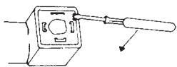
- Remove screw
- Insert the screwdriver in the slot and press downwards.
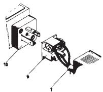
On devices with terminal connection housing (300) the terminal board is available after removing the terminal box lid.
Caution: Switch of voltage
1.3 Pressure connection
Installation: Directly on the pipeline (pressure gauge connection G^1/2 ) or with 2 screws (4 mm) on a level surface. Tighten only on the hexagonal of the pressure organ, never use the housing or plug as a lever arm.
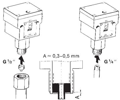
External thread G^1 / 2
(Pressure gauge connection)
When using flat seals, turn in the centering screw
(depth A approx. 0,3 - 0,5mm)
Internal thread G 1/4"
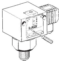
1.4 Setting the switching pressure
The switching pressure is set using the setting spindle. Before setting loosen the setscrew located above the scale by approx. 2 turns and tighten it again after setting.
The scale value corresponds to the upper switching point (for rising pressure). The lower switching point (for falling pressure) is lower by the switching difference. The scale serves as estimated value scale, a pressure gauge is required for accurate settings.
On terminal connection housings the setting screw is available after removing the cover.
Caution: Switch off voltage.
1.5 External electrical interlock in the switchgear cabinet (Circuit proposal)
A pressure monitor can also be used as a limiter if an electrical interlock is connected in series. In pressure limitation in steam and hot water boilers, the external interlock is permissible only if it is assured that the pressure monitor is of "special design".
1.5.1 Maximum pressure limitation with external interlock
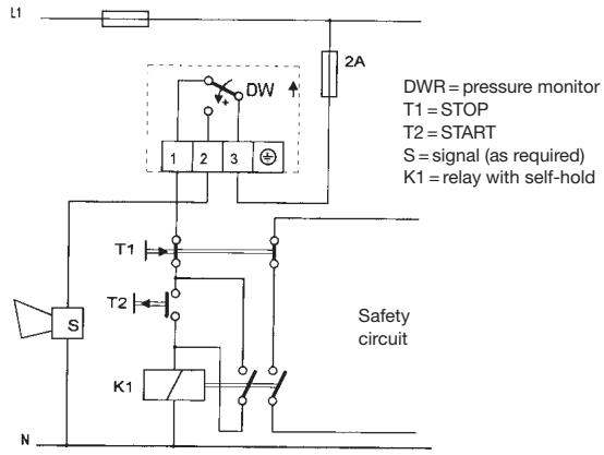
When the interlock circuit shown above is used, the requirements according to DIN 57 116/ VDE 0116 are fulfilled if the electrical plant, such as contactors or relays, correspond to the external interlock circuit VDE 0660 or VDE 0435 respectively.
2. Pressure monitors with adjustable switching difference DWAMV...
2.1 Technical data as for 1.1
2.2 Electrical connection as for 1.2
2.3 Pressure connection as for 1.3
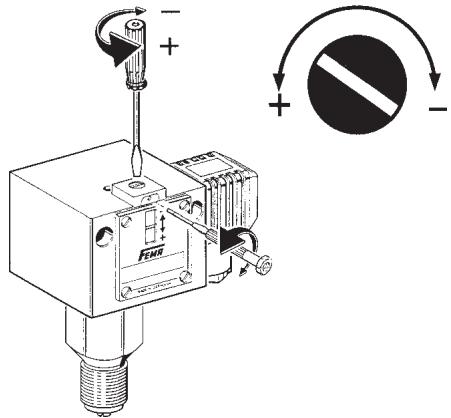
2.4 Setting
On spindle each is available for setting the switch pressure and the switching difference.
Both spindles are arranged concentrically. The outer spindle with larger diameter influences the upper switching point, the switching difference and thus the lower switching point, is changed with the small grub screw located internally.
The action direction is indicated by the arrow direction.


Setting sequence
a) Upper switching point (with increasing pressure), with outer spindle, according to scale or pressure gauge
b) Switching difference (with decreasing pressure), with small, internal group screw, results in lower switching point.
When the switching difference is changed, the upper switch-off point remains unchanged, the lower switching point is shifted by the switching difference.
$$ R S P = S P - x d $$
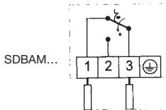
3. Maximum pressure limiters with mechanical interlock of the switching state (SDBAM...)
Instead of the microswitch with automatic reset, a "bistable" microswitch is installed in the limiters.
When the pressure reaches the value set on the scale, the microswitch switches over and remains in this position. The catch can be relaxed by pressing in the unlocking button (marked on the scale side of the switching device by a red dot). The limiter can not be unlocked until the pressure has decreased by a certain amount.
3.1 Technical data as for 1.1
3.2 Electrical connection
Switching over and interlocking on rising temperature.
Connection of control circuit to terminal 1 and 3.
3.3 Unlocking of maximum pressure limiters SDBAM
By pressing in the button red on the scale side of the switching device (e.g. with screwdriver or ball-point pen).
Unlocking does not become effective until the pressure on the probe has dropped below the set.
For SDBAM 1
For SDBAM 2.5
For SDBAM 6
approx. 0.12 bar
approx. 0.15 bar
approx. 0.4 bar
For SDBAM 625
For SDBAM 16
For SDBAM 32
3.4 Setting as for 1.4
Please note:
For maximum pressure limiters the scale value corresponds to the upper switching point.
4. Pressure limiters with gold plated contact DWAM...-213, ...-513
Gold plated contacts are used exclusively in the low voltage range in order to keep the transit resistance at the contacts low.
4.1 Technical Data as for 1.1
Switching capacity
max. 24 V DC
max. 100mA
min. 5 V DC
min. 2 mA
At higher voltages and currents, the gold layer on the contacts will be damaged.
All other data correspond to the basic equipment.
Utilisation
Vapeur
Eau chaude
Attention: Couper la tension.
$$ R S P = S P - x d $$
Manufactured for and on behalf of the Environmental and Combustion Controls Division of Honeywell Technologies Sàrl, Ecublens, Route du Bois 37, Switzerland by its Authorized Representative:
FEMA Regelerge
Honeywell GmbH
Böblinger Straße 17
71101 Schonaich
Deutschland
Telefon 07031/637-02
Telefax 07031/637-850
FEMA Controls
Honeywell GmbH
Böblinger Straße 17
71101 Schonaich
Germany
Phone 07031/637-02
Fax 07031/637-850
7156.722/14
MU2B-0240GE51 R0508
- Action direction
- Sensor
- Testing basis for type test according PED 97/23EC
- Certificate No.
- Important note:
- Installation and commissioning
- Safety instructions
- PLT protection devices
- Basic equipment of the pressure monitors / pressure limiter
- Technical Data (basic equipment)
- Switch
- Switching capacity
- Installation position
- Max. ambient temperature
- Max. medium temperature
- Switching difference
- Pressure connection
- Switching device
- Degree of protection
- Materials
- (Lower range limit)
- (Upper range limit)
- The following applies for all devices:
- Electrical wiring
- Connection layout
- Wiring
- Pressure connection
- External thread G1 / 2
- Setting the switching pressure
- External electrical interlock in the switchgear cabinet (Circuit proposal)
- Maximum pressure limitation with external interlock
- Pressure monitors with adjustable switching difference DWAMV...
- Setting sequence
- Maximum pressure limiters with mechanical interlock of the switching state (SDBAM...)
- Technical data as for 1.1
- Electrical connection
- Unlocking of maximum pressure limiters SDBAM
- Setting as for 1.4
- Please note:
- Pressure limiters with gold plated contact DWAM...-213, ...-513
- Technical Data as for 1.1
- Utilisation
- FEMA Regelerge
- FEMA Controls
Brand : HONEYWELL
Model : DWAMV
Category : Electronic pressure switch