
6240810X61 - Snowplows MURRAY - Free user manual and instructions
Find the device manual for free 6240810X61 MURRAY in PDF.

User questions about 6240810X61 MURRAY
0 question about this device. Answer the ones you know or ask your own.
Ask a new question about this device
Download the instructions for your Snowplows in PDF format for free! Find your manual 6240810X61 - MURRAY and take your electronic device back in hand. On this page are published all the documents necessary for the use of your device. 6240810X61 by MURRAY.
USER MANUAL 6240810X61 MURRAY
HAZARD SYMBOLS AND THEIR MEANINGS 4
OPERATING SYMBOLS AND THEIR MEANINGS 4
ASSEMBLY 9
OPERATION 9
MAINTENANCE CHART 11
MAINTENANCE 11
TROUBLESHOOTING CHART 15
Figures (Example: Figure 1) are located on the inside front and back pages of this manual located before the parts list.
General Information
This instruction book is written for a person with some mechanical ability. Like most service books, not all the steps are described. Steps on how to loosen or tighten fasteners are steps anyone can follow with some mechanical ability. Read and follow these instructions before you use the unit.
Know your product: If you understand the unit and how the unit operates, you will get the best performance. As you read this manual, compare the illustrations to the unit. Learn the location and the function of the controls. To help prevent an accident, follow the operating instructions and the safety rules. Keep this manual for future reference.
IMPORTANT: Many units are not assembled and are sold in cartons. It is the responsibility of the owner to make sure the assembly instructions in this manual are exactly followed. Other units are purchased in an assembled condition. On assembled units, it is the responsibility of the owner to make sure the unit is correctly assembled. The owner must carefully check the unit according to the instructions in this manual before it is first used.
Need Assistance?
If you need additional information on assembling, operating, or servicing your equipment contact your local Dealer.


This manual contains safety information to make you aware of the hazards and risks associated with snow
throwers, and how to avoid them. The snow thrower is designed and intended for removal of snow, and should not be used for any other purpose. It is important that you read and understand these instructions, and anyone operating the equipment read and understand these instructions.

WARNING
The engine exhaust from this product contains chemicals known to the State of California to cause cancer, birth defects, or other reproductive harm.
A signal word (DANGER, WARNING, or CAUTION) is used with the alert symbol to indicate the likelihood and the potential severity of injury. In addition, a hazard symbol may be used to represent the type of hazard.

DANGER indicates a hazard which, if not avoided, will result in death or serious injury.

WARNING indicates a hazard which, if not avoided, could result in death or serious injury.

CAUTION indicates a hazard which, if not avoided, might result in minor or moderate injury.
CAUTION, when used without the alert symbol, indicates a situation that could result in damage to the equipment.
Controls & Equipment Features (see Figure 1)
Traction Drive Lever (1) - Select the forward or reverse direction of travel.
Crank Assembly (2) - Changes the direction of the discharge chute.
Chute Deflector (3) - Changes the distance the snow is thrown.
Discharge Chute (4) - Changes the direction the snow is thrown.
Auger Drive Lever (5) - Starts and stops the auger (snow gathering and throwing) which also propels the snowthrower.
Speed Shift Lever (6) - Selects the speed of the snow thrower.
Height Adjust Skid (7) - Adjusts the ground clearance of the auger housing.
Drift Cutters (18) - (if equipped) Cuts a path through snow higher than the auger housing.
Shear Bolts (19) - To protect the machine, special shear bolts are designed to break is an object becomes lodged in the auger housing. The use of a harder bolt will destroy the protection provided by the shear bolt.
Engine Features
Safety Key (8) - Must be inserted to start the engine.
Primer Button (9) - Injects fuel directly into the carburetor for fast starts in cold weather.
Electric Start Button (10) - On electric start models, used to start the engine.
Switch Box (11) - On electric start models, used to attach a 220 volt electric power cord.
Recoil Starter Handle (12) - Use to manually start the engine.
Stop Switch (13) - Use to stop the engine.
Choke Control (14) - Use to start a cold engine.
Hazard Symbols and their meanings
These symbols are used on your equipment and defined in your operating manual. Review and understand the meanings. The use of one of these symbols combined with a signal word will alert you to potential hazards and how to avoid them.

Safety Alert - Identifies safety information about hazards that can result in personal injury.

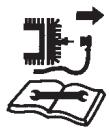
Operator's Manual - Read and understand before performing any activity or running equipment.

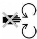
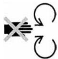
Rotating auger

Rotating impeller

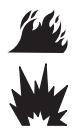
Fire

Explosion
Toxic fumes

Shock
Rotating gears
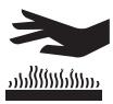
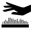
Hot Surface
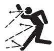
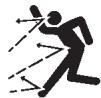
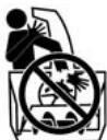
Thrown objects

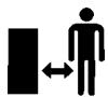
Keep a safe distance from the equipment.
Never reach into rotating parts.
Shut off engine and remove spark plug connector before performing maintenance or repair work.
Operating Symbols and their meanings
These symbols are used on your equipment and defined in your operating manual. It is important that you review and understand the meanings. Failure to understand the symbols might result in harm to you.

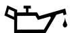
Oil

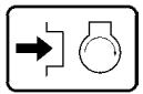
On Off


Forward
Neutral
Reverse

Primer bulb

Throttle

Choke off

Choke on

Stop

Slow

Fast

Engage

Traction

Auger Collector

Auger Clutch

Drive Clutch
Engage

Disengage

Discharge Chute
LEFT

RIGHT

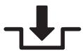
Chute Deflector
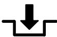
UP

DOWN


DANGER
Avoid death or serious injury from rotating auger.
Keep hands, feet and clothing away.
Unclogging discharge chute is a hazardous activity.
- Never attempt to clear auger of debris or clogged snow while equipment is engaged or engine is running.
- Stop engine and disconnect spark plug wire when performing maintenance on equipment.
- Never leave the equipment unattended while engine is running. Always disengage the auger and traction controls, stop engine, and remove keys.
- Keep children, pets, and others out of the area during operation. Children are often attracted to the equipment. Be mindful of all persons present.
- Keep all loose clothing far away from front of snow thrower and auger. Scarves, mittens, dangling drawstrings, loose clothes and pants can quickly become caught in the rotating device and dismemberment will occur. Tie up long hair and remove jewelry.
- The snow thrower is intended to remove snow only. Do not use for purposes other than what is intended.
- Do not clear snow across the face of slopes. Exercise extreme caution when changing direction on slopes. Do not attempt to clear steep slopes.
- Do not use the snow thrower on surfaces above ground level such as roofs of residences, garages, porches or other such structures or buildings.

DANGER
Objects can be picked up by auger and thrown from chute. Never throw snow toward people or cars, and never allow anyone in front of the snow thrower.
- Be aware of your environment while operating equipment. Running over items such as gravel, doormats, newspapers, toys, and rocks hidden under snow, can all be thrown from chute or jam in the auger.
- Always be aware of the direction the snow is being thrown. Nearby pedestrians, pets or property may be harmed by objects being thrown.
- Familiarize yourself with the area you plan to work. Mark off boundaries of walkways and driveways to prevent property damage from thrown objects.
- Take caution when snow throwing in unfamiliar areas. Stay alert for hidden hazards and traffic.
- After striking a foreign object, turn engine OFF, wait for moving parts to cease movement, and check immediately for damage. If damaged, repair before starting and operating snow thrower.
- With engine OFF, wait for moving parts to stop and always use a stick to clear discharge chute.
- If unit vibrates abnormally, turn engine OFF. Vibration is generally a warning of trouble. See an authorized dealer if necessary for repairs.


DANGER
Discharge chute contains rotating impeller to throw snow. Never clear or unclog discharge chute with your hands, or while engine is running.
Fingers can quickly become caught and traumatic amputation or severe laceration can result.
Unclogging the discharge chute is a hazardous activity.
- Never place hands in or near discharge chute.
- With engine OFF, wait for all moving parts to cease movement, then with a stick, clear the chute.
- Clogged snow can hide other obstructions in the chute and cause damage to the equipment, impeller or auger. Take precautions when restating the equipment after snow removal.

WARNING

Engines give off carbon monoxide, an odorless, colorless, poison gas.
Breathing carbon monoxide can cause nausea, fainting or death.
- Start and run engine outdoors.
- Do not start or run engine in enclosed area, even if doors or windows are open.
WARNING
Gasoline and its vapors are extremely flammable and explosive. Fire or explosion can cause severe burns or death.
WHEN ADDING FUEL
- Turn engine OFF and let engine cool at least 2 minutes before removing gas cap.
- Fill fuel tank outdoors or in well-ventilated area.
- Do not overfill fuel tank.
- Keep gasoline away from sparks, open flames, pilot lights, heat, and other ignition sources.
- Check fuel lines, tank, cap, and fittings frequently for cracks or leaks. Replace if necessary.
WHEN STARTING ENGINE
- Make sure spark plug, muffler, fuel cap and air cleaner are in place.
- Do not crank engine with spark plug removed.
- If fuel spills, wait until it evaporates before starting engine.
- If engine floods, set choke to OPEN/RUN position, place throttle in FAST and crank until engine starts.
WHEN OPERATING EQUIPMENT
- Do not choke carburetor to stop engine.
WHEN TRANSPORTING EQUIPMENT
- Transport with fuel tank EMPTY.
WHEN STORING GASOLINE OR EQUIPMENT WITH FUEL IN TANK
- Store away from furnaces, stoves, water heaters or other appliances that have pilot light or other ignition source because they can ignite gasoline vapors.
WARNING: This machine is capable of amputating hands and feet and throwing objects. Read these safety rules and follow them closely. Failure to obey these rules could result in loss of control of unit, severe personal injury or death to you, or bystanders, or damage to property or equipment. The triangle in text signifies important cautions or warnings which must be followed.
Safe Operation Practices for Snowthrowers
IMPORTANT: Safety standards require operator presence controls to minimize the risk of injury. Your snowthrower is equipped with such controls. Do not attempt to defeat the function of the operator presence control under any circumstances.
Training
- Read, understand, and follow all instructions on the machine and in the manuals before operating this unit. Be thoroughly familiar with the controls and the proper use of the equipment. Know how to stop the unit and disengage the controls quickly.
- Never allow children to operate the equipment. Never allow adults to operate the equipment without proper instruction.
- Keep the area of operation clear of all persons, particularly small children and pets.
- Exercise caution to avoid slipping or falling especially when operating in reverse.
Preparation
- Thoroughly inspect the area where the equipment is to be used and remove all doormats, sleds, boards, wires, and other foreign objects.
- Disengage all clutches and shift into neutral before starting the engine (motor).
- Do not operate the equipment without wearing adequate winter outer garments. Wear footwear that will improve footing on slippery surfaces. Avoid loose fitting clothing that can get caught in moving parts.
- Handle fuel with care; it is highly flammable.
a. Use an approved fuel container.
b. Never add fuel to a running engine or hot engine.
c. Fill fuel tank outdoors with extreme care. Never fill fuel tank indoors. Replace fuel cap securely and wipe up spilled fuel.
d. Never fill containers inside a vehicle or on a truck or trailer bed with a plastic liner. Always place containers on the ground, away from your vehicle, before filling.
e. When practical, remove gas-powered equipment from the truck or trailer and refuel it on the ground. If this is not possible, then refuel such on a trailer with a portable container, rather than from a gasoline dispenser nozzle.
f. Keep nozzle in contact with the rim of the fuel tank or container opening at all times, until refueling is complete. Do not use a nozzle lock-open device.
g. Replace gasoline cap securely and wipe up spilled fuel.
h. If fuel is spilled on clothing, change clothing immediately.
- Use extension cords and receptacles as specified by the manufacturer for all units with electric drive motors or electric starting motors.
- Adjust the collector housing height to clear gravel or crushed rock surfaces.
-
Never attempt to make any adjustments while the engine (motor) is running (except when specifically recommended by manufacturer).
-
Let engine (motor) and snowthrower adjust to outdoor temperatures before starting to clear snow.
- Always wear safety glasses or eye shields during operation or while performing an adjustment or repair to protect eyes from foreign objects that may be thrown from the machine.
- Never operate the snowthrower without proper guards, plates or other safety protective devices in place.
Operation
- Do not put hands or feet near or under rotating parts. Keep clear of the discharge opening at all times.
- Exercise extreme caution when operating on or crossing gravel drives, walks or roads. Stay alert for hidden hazards or traffic.
- After striking a foreign object, stop the engine (motor), remove the wire from the spark plug, disconnect the cord on electric motors, thoroughly inspect snowthrower for any damage, and repair the damage before restarting and operating the snowthrower.
- If the unit should start to vibrate abnormally, stop the engine (motor) and check immediately for the cause. Vibration is generally a warning of trouble.
- Stop the engine (motor) whenever you leave the operating position, before unclogging the collector/impeller housing or discharge chute and when making any repairs, adjustments, or inspections.
- When cleaning, repairing, or inspecting, make certain the collector/impeller and all moving parts have stopped. Disconnect the spark plug wire and keep the wire away from the spark plug to prevent accidental starting.
- Do not run the engine indoors, except when starting the engine and for transporting the snowthrower in or out of the building. Open the outside doors; exhaust fumes are dangerous (containing CARBON MONOXIDE, an ODDORLESS and DEADLY GAS).
- Exercise extreme caution when operating on slopes. Do not attempt to clear steep slopes.
- Never operate the snowthrower without proper guards, plates, or other safety protective devices in place and working.
- Never direct the discharge toward people or areas where property damage can occur. Keep children and others away.
- Do not overload the machine capacity by attempting to clear snow at too fast a rate.
- Never operate the machine at high transport speeds on slippery surfaces. Look behind and use care when operating in reverse.
- Disengage power to the collector/impeller when snowthrower is transported or not in use.
- Use only attachments and accessories approved by the manufacturer of the snowthrower (such as cabs, tire chains, etc.).
- Never operate the snowthrower without good visibility or light. Always be sure of your footing and keep a firm hold on the handles. Walk, never run.
16.Never touch a hot engine or muffler. -
Never operate the snowthrower near glass enclosures, automobiles, window wells, drop-offs, and the like without proper adjustment of the snow discharge angle.
-
Never direct discharge at bystanders or allow anyone in front of the unit.
- Never leave a running unit unattended. Always disengage the auger and traction controls, stop engine, and remove keys.
- Do not operate the unit while under the influence of alcohol or drugs.
- Keep in mind the operator is responsible for accidents occurring to other people or property.
- Data indicates that operators, age 60 years and above, are involved in a large percentage of power equipment-related injuries. These operators should evaluate their ability to operate the unit safely enough to protect themselves and others from injury.
- DO NOT wear long scarves or loose clothing that could become entangled in moving parts.
- Snow can hide obstacles. Make sure to remove all obstacles from the area to be cleared.
Children
Tragic accidents can occur if the operator is not alert to the presence of children. Children are often attracted to the unit and the operating activity. Never assume that children will remain where you last saw them.
- Keep children out of the area and under the watchful care of another responsible adult.
- Be alert and turn off if children enter the area.
- Never allow children to operate the unit.
- Use extra care when approaching blind corners, shrubs, trees, or other objects that may obscure vision.
Clearing A Clogged Discharge Chute
Hand contact with the rotating impeller inside the discharge chute is the most common cause of injury associated with snowthrowers. Never use your hand to clean out the discharge chute.
To clear the chute:
- SHUT OFF THE ENGINE.
- Wait 10 seconds to be sure the impeller blades have stopped rotating.
- Always use a clean out tool, not your hands.
Service, Maintenance And Storage
-
Check shear bolts (pins) and other bolts at frequent intervals for proper tightness to be sure the equipment is in safe working condition.
-
Never store the machine with fuel in the tank inside a building where ignition sources are present such as hot water and space heaters, or clothes dryers. Allow the engine to cool before storing in any enclosure.
- Always refer to operator's manual for important details if the snowthrower is to be stored for an extended period.
- Maintain or replace safety and instruction labels as necessary.
- Run the machine a few minutes after throwing snow to prevent freeze-up of the collector/impeller.
- If fuel is spilled, do not attempt to start the engine but move the machine away from the area of spillage and avoid creating any source of ignition until fuel vapors have dissipated.
- Always observe safe refueling and fuel handling practices when refueling the unit after transportation or storage.
- Always follow the engine's manual instructions for storage preparations before storing the unit for both short and long term periods.
- Always follow the engine manual instructions for proper start-up procedures when returning the unit to service.
- Keep nuts and bolts tight and keep equipment in good condition.
- Never tamper with safety devices. Check their proper operation regularly and make necessary repairs if they are not functioning properly.
- Components are subject to wear, damage, and deterioration. Frequently check components and replace with manufacturer's recommended parts, when necessary.
- Check control operation frequently. Adjust and service as required.
- Use only factory authorized replacement parts when making repairs.
- Always comply with factory specifications on all settings and adjustments.
- Only authorized service locations should be utilized for major service and repair requirements.
- Never attempt to make major repairs on this unit unless you have been properly trained. Improper service procedures can result in hazardous operation, equipment damage and voiding of manufacturer's warranty.
Emissions
- Engine exhaust from this product contains chemicals known, in certain quantities, to cause cancer, birth defects, or reproductive harm.
- If available, look for the relevant Emissions Durability Period and Air Index information on the engine emissions label.
Ignition System
- This spark ignition system complies with Canadian ICES-002.
Read and follow the assembly and adjustment instructions for your snow thrower. All fasteners are in the parts bag. Do not discard any parts or material until the unit is assembled.

WARNING: Before doing any assembly or maintenance to the snow thrower, remove the wire
from the spark plug.
NOTE: In this instruction book, left and right describe the location of a part from the operator's position behind the unit.
NOTE: Torque is measured in foot pounds (metric N.m). This measurement describes how tight a nut or bolt must be. The torque is measured with a torque wrench.
NOTE: Fasteners and loose parts are shown at full size in Figure 2 on page 170.
NOTE: Illustrations are located on page 2 and on pages 171 through 176.
Tools Required
1 Knife
1 Pliers
2 1/2 inch open end wrenches
2 9/16 inch open end wrenches
2 3/4 inch open end wrenches
1 Measuring tape or ruler
1 Screwdriver
How To Remove The Snow Thrower From The Carton
- (Figure 3) The snow thrower is shown in the shipping position.
- Remove packing material from wheels, handle, and auger housing.
- Locate and remove the parts bag (some models do not have a parts bag).
- Cut open the end of the carton next to the handle.
- To roll the snowthrower off of the carton, pull on the handle.
CAUTION: DO NOT back over cables.
- Remove any packing material that remains from handle and auger housing.
- Cut any plastic shipping ties that may secure the control cables to the LOWER HANDLE.
- If the control cables have become disconnected from the control levers, then attach the cable to the levers (see Owner's Manual for illustration of cable and lever).
How To Assemble The Handle And Crank Assembly
- (Figure 4) Loosen, but do not remove, the fasteners (1) in the upper holes of the lower handle.
- Remove the fasteners and the crank assembly eyebolt (11) from the lower holes of the lower handle.
- (Figure 1) Put the shift lever (6) into first forward position.
-
(Figure 4) Raise the upper handle (2) to the operating position. NOTE: Make sure the cables are not caught between the upper and lower handle.
-
Install the fasteners and the crank assembly eyebolt (11) that were removed in step 2. DO NOT tighten until all fasteners are in place.
- (Figure 5) Attach the crank rod (15) to the universal joint assembly (16) with the hair pin (12).
- (Figure 4) Tighten nut on eye bolt (11). Make sure eye bolt (11) is properly aligned and the crank (18) can freely rotate.
- Tighten all handle fasteners.
How To Install The Knob(s) (Figure 6)
NOTE: If knob(s) are already installed, go to the next selection.
- Attach the knob (3) onto the speed shift lever (2). On some models, the knob (3) is attached. To lock in position, tighten the hex jam nut (1) against the bottom of the knob (3).
- Make sure the speed shift lever (2) functions correctly. Move the speed shift lever (2) through all speeds.
How To Assemble The Chute Deflector
- (Figure 4) Turn the crank assembly (18) counterclockwise until crank assembly (18) stops.
- (Figure 7) Fasten chute deflector (2) to flange (4) with carriage bolts (1). Make sure to install with head of the carriage bolts (1) on the inside of the flange (2).
- Fasten with washers (5) and locknuts (6).
- Tighten locknuts (6) securely.
NOTE: Make sure all carriage bolts in flange are tight. DO NOT OVERTIGHTEN.
Check The Cables
- (Figure 8) Check the traction drive cable (1) and the auger drive cable (2). If the bottom of the cables have become disconnected, reinstall the cables.
- (Figure 10) If the top of the cables (5) have become disconnected from the drive levers (6), attach the cables (5) to the "Z" fitting (7).
How To Set The Skid Height (Figure 1)
The snow thrower is equipped with height adjustable skids (7) mounted on the outside of the auger housing (4). To adjust the height of the skids, see "How To Adjust The Height Of The Skids" in the Maintenance section.
How To Set The Length Of The Cables
The cables were adjusted at the factory and no adjustments should be necessary. However, after the handles are put in the operating position, the cables can be too tight or too loose. If an adjustment is necessary, see "How To Check And Adjust The Cables" in the Service And Adjustment section.
How To Assemble The Drift Cutter (if equipped)
Drift cutters are used to cut a path through snow deeper than the auger housing.
- (Figure 11) Loosen the fasteners (2) that secure the drift cutters (1) to the auger housing.
- Raise the drift cutters (1) to the desired height.
- Tighten the fasteners (2).
How To Prepare The Engine
NOTE: The engine was shipped from the factory filled with oil. Check the level of the oil. Add oil as needed.
WARNING: Follow the engine manufacturer's instructions for the type of fuel and oil to use. Always use a safety fuel container. Do not smoke when adding gasoline to the engine. When inside an enclosure, do not fill with gasoline. Before you add fuel, stop the engine. Let the engine cool for several minutes.
Check the oil. See the engine manufacturer's instructions for the type of fuel and oil to use. Before you use the unit, read the information on safety, operation, maintenance, and storage.
Important! Before You Start Operating
Check the fasteners. Make sure all fasteners are tight.
On electric start models, the unit was shipped with the starter cord plugged into the engine. Before operating, unplug the starter cord from the engine.
OPERATION
NOTE: Illustrations are located on page 2 and on pages 171 through 176.
CAUTION: Use only attachments and accessories approved by the manufacturer of the snow thrower (such as tire chains, electric start kits, etc.).
Know Your Snow Thrower (Figure 1)
Read this Instruction Book and safety rules before operation the snow thrower. Compare the illustration with your snow thrower to familiarize yourself with the location of various controls and adjustments.
How To Control The Discharge Of The Snow

WARNING: Never direct the discharge of snow toward bystanders.

WARNING: Always stop the engine before unclogging the discharge chute or the auger housing and leaving the snow thrower.
- (Figure 1) Turn the crank assembly (2) to change the discharge direction of the snow.
- (Figure 12) Loosen the wing knob (1) on the chute deflector (2) and move the chute deflector (2) to set the distance. Move the chute deflector (2) UP for more distance, DOWN for less distance. Then tighten the wing knob (1).
How To Stop The Snow Thrower (Figure 1)
- To stop discharging snow, release the auger drive lever (5).
- To stop the wheels, release the traction drive lever (1).
- To stop the engine, move the stop switch (13) to the OFF position.
CAUTION: To stop the engine, do not move the choke control to CHOKE position. Backfire or engine damage can occur.
How To Go Forward or Backward (Figure 1)
- To change the ground speed, first release the traction drive lever (1) and then move the speed shift lever (6) to the desired speed.
- Ground speed is determined by snow conditions. Select the speed by moving the speed shift lever (6) into the appropriate notch on the shift lever plate.
Speed 1,2 Wet,Heavy
Speed 3 Light
Speed 4 Very Light
Speed 5, 6 Transport only
- To go forward, engage the traction drive lever (1). Maintain a firm hold on the handle as the snow thrower starts to move forward. Guide the snow thrower by moving the handle either left or right. Do not attempt to push the snow thrower.
- To go backward, release the tractor drive lever (1).
- Move the speed shift lever (6) into either first or second reverse.
- Engage the traction drive lever (1).
IMPORTANT: Do not move the speed shift lever (6) while the traction drive lever (1) is engaged.
How To Throw Snow (Figure 1)
- Engage the auger drive lever (5).
- To stop throwing snow, release the auger drive lever (5).

WARNING: The operation of any snow thrower can result in foreign objects being thrown into the eyes,
which can result in severe eye damage. Always wear safety glasses or eye shields while operating the snow thrower. We recommend standard safety glasses or use a wide vision safety mask over your glasses.
How To Use The Wheel Lockout Pin (Figure 13)
- The right hand wheel is secured to the axle with a klick pin (1). This unit was shipped with this klick pin (1) through the wheel hole in the locked position (2).
- For ease of maneuverability in light snow conditions, change the klick pin (1) to an unlocked position (3).
- Disconnect the klick pin (1) from the wheel locked position (2). Push the klick pin (1) through the unlocked axle hole only. The unit is now in the single wheel drive unlocked position (3).
Before Starting The Engine
- Before you service or start the engine, familiarize yourself with the snow thrower. Be sure you understand the function and location of all controls.
- Check the tension of the clutch cable before starting the engine. See "How To Adjust The Clutch Cable" in the Maintenance section of this manual.
- Make sure that all fasteners are tight.
- Make sure the height adjust skids are properly adjusted. See "How To Adjust The Height Of The Skids" in the Maintenance section of this manual.
- Check the air pressure in the tires. The correct air pressure is 14 PSI (1 BAR) to 17 PSI (1.25 BAR). Do not exceed the maximum amount of air pressure shown on the side of the tire.
How To Stop The Engine (Figure 1)
- Push the stop switch (13) to the OFF position.
- Pull out the safety key (8).
CAUTION: To stop the engine, do not move the choke control to CHOKE position.
Backfire or engine damage can occur.
How To Start The Engine (Figure 1)
Models equipped with an Electric Starter
NOTE: An electric starter kit can be added to recoil start engines. Electric starter kits are available from your nearest authorized service center.

WARNING: The starter is equipped with a three-wire power cord and plug and is designed to operate on
220 volt A.C. household current. The power cord must be properly grounded at all times to avoid the possibility of electrical shock which can injure the operator. Carefully follow all instructions in the "How To Start The Engine" section. Make sure that your house wiring is a three-wire grounded system. If you are not sure, ask a licensed electrician. If your house wire system is not a three-wire grounded system, do not use this electric starter under any conditions. If your system is grounded but a three-hole grounded receptacle is not available to start the engine, have a three-hole grounded receptacle installed by a licensed electrician. To connect a 220 volt A.C. power cord, always connect the power cord to the switch box (11) on the engine first. Then, plug the other end into the three-hole grounded receptacle. When disconnecting the power cord, always unplug the end from the three-hole grounded receptacle first.
How To Start A Cold Engine (Figure 1)
- Check the engine oil.
- Fill the fuel tank with regular unleaded petrol. See "How To Prepare The Engine".
-
Make sure the traction drive lever (1) and the auger drive lever (5) are in the disengaged (released) position.
-
Push the stop switch (13) to the ON position.
- Push in the safety key (8).
- Rotate the choke knob (14) to the CHOKE position.
- (Electric Start) Connect the power cord to the starter motor located on the engine.
- (Electric Start) Plug the other end of the power cord into a three-hole, grounded 220 VOLT, A.C. receptacle. (See the WARNING in this section).
- Push the primer button (9). Every time you push the primer button (9), wait two seconds. For the number of times required to push the primer button (9), see the engine manufacturer's instructions.
- (Electric Start) Push on the electric start button (10) until the engine starts. Do not crank for more than 5 seconds at a time. Wait one minute between starts to allow the starter to cool.
- (Recoil Start) Slowly pull the recoil starter handle (12) until resistance is felt and then pull rapidly to start the engine. Do not allow the recoil starter handle (12) to snap back. Slowly return the recoil starter handle (12).
- If the engine does not start in 5 or 6 tries, See the "Trouble Shooting Chart" Instructions.
- Allow the engine to warm up for several minutes. As the engine warms up, adjust the choke knob (14) toward the RUN position. Wait until the engine runs smoothly before each choke adjustment.
- (Electric Start) First disconnect the power cord from the three-hole receptacle. Then, disconnect the power cord from the starter motor.
NOTE: In temperatures below 0^ (-18^) allow the engine to warm up for several minutes before blowing snow.

WARNING: Never run the engine indoors or in enclosed, poorly ventilated areas. Engine exhaust
contains carbon monoxide, an odorless and deadly gas. Keep hands, feet, hair and loose clothing away from any moving parts located on the engine or the snow thrower. The temperature of muffler and nearby areas may exceed 150^ (66^) . Avoid these areas.
How To Start A Warm Engine (Figure 1)
If an engine has been running and is still warm, leave the choke control (14) in the off position and do not push the primer button (9). If the engine fails to start, follow the instructions "How To Start A Cold Engine".
NOTE: Do not use the primer button (9) to start a warm engine.
How To Start An Engine With A Frozen Electric Starter (Figure 1)
If the electric starter is frozen and will not turn the engine, follow the instructions below.
- Pull as much starter rope as possible out of the starter.
- Release the starter handle and let it snap back against the starter. Repeat until the engine starts.
Warm engines will cause condensation in cold weather. To prevent possible freeze-up of recoil starter and engine controls, proceed as follows after each snow removal job.
- Run the snow thrower a few minutes after throwing snow to prevent freeze-up of the auger/impeller.
- With engine off, allow engine to cool for several minutes.
- Pull starter rope very slowly until resistance is felt, then stop. Allow the starter rope to recoil. Repeat three times.
- With the engine not running, wipe all snow and moisture from the carburetor cover in area of controls and levers. Also, move the choke control and starter handle several times.
How To Remove Snow or Debris From The Auger Housing

WARNING: Do not attempt to remove snow or debris that may become lodged in auger housing
with your hands. Use the clean-out tool or a pry bar to remove snow or debris.
(Figure 21) On some models, a clean-out tool (1) is attached to the top of the auger housing. Use the clean-out tool (1) to remove snow from the auger housing.
- (Figure 1) Release the auger drive lever (5).
- Pull out the safety key (8).
- Disconnect the spark plug wire.
- Do not place your hands in the auger housing (4) or the discharge chute (3).
- (Figure 21) Use the clean-out tool (1) or a pry bar to remove any snow or debris.
Snow Throwing Tips
- For maximum snow thrower efficiency in removing snow, adjust ground speed. Go slower in deep, freezing or wet snow. If the wheels slips, reduce forward speed.
- Most efficient snow throwing is accomplished when the snow is removed immediately after if falls.
CAUTION: Do not overload the machine capacity by attempting to clear snow at too fast a rate.
- For complete snow removal, slightly overlap each previous path.
- Whenever possible, discharge the snow down wind.
- For normal usage, set the skids so that the scraper bar is 1/8 (3 mm) above the skids. For extremely hard-packed snow surfaces, adjust the skids upward so that the scraper bar touches the ground.
- Rocks and gravel must not be picked up and thrown by the machine. On gravel or crushed rock surfaces, set the skids at 1-1/4 inch (32 mm) below the scraper bar. See "How To Adjust The Height Of The Skids" in the Maintenance section.
- After each snow throwing job, allow the engine to idle for a few minutes. The snow and accumulated ice will melt off the engine.
- Clean the snow thrower after each use.
- Remove ice, snow and debris from the entire snow thrower. Flush with water to remove all salt or other chemicals. Wipe snow thrower dry.
MAINTENANCE CHART
CUSTOMER RESPONSIBILITIES
| SERVICE RECORDS Fill in dates as you complete regular service. | Before Each Use | First 2 Hours | Every 5 Hours | Every 10 Hours | Every 25 Hours | Each Season | Before Storage | SERVICE DATES |
| Check Engine Oil Level | ✓ | ✓ | ✓ | |||||
| Change Engine Oil | ✓ | ✓ | ||||||
| Check And Tighten All Screws and Nuts | ✓ | ✓ | ||||||
| Check Spark Plug | ✓ | ✓ | ||||||
| Adjust Drive Belt | ✓ | ✓ | ✓ | |||||
| Check Fuel | ✓ | |||||||
| Drain Fuel | ✓ | |||||||
| Check Auger Clutch Cable Adjustment (See Cable Adjustment) | ✓ | ✓ | ||||||
| Check Traction Clutch Cable Adjustment (See Cable Adjustment) | ✓ | ✓ | ||||||
| Lubricate All Pivot Points | ✓ | ✓ | ||||||
| Lubricate Auger Shaft (See Shear Bolt Replacement) | ✓ | ✓ | ||||||
| Lubricate Drive Chains and Sprockets | ✓ | ✓ |
MAINTENANCE
NOTE: Illustrations are located on page 2 and on pages 171 through 176.
Use the following maintenance section to keep your unit in good operating condition. All the maintenance information for the engine is in the engine manufacturer's instructions. Before you start the engine, read this book.

WARNING: Before you make an inspection, adjustment (except carburetor), or repair, disconnect
the wire from the spark plug.
General Recommendations
The warranty on this snow thrower does not cover items that have been subjected to operator abuse or negligence. To receive full value from the warranty, the operator must maintain the snow thrower as instructed in this manual.
Some adjustments must be made periodically to properly maintain the snow thrower.
After Each Use
- Check for any loose or damaged parts.
- Tighten any loose fasteners.
Check and maintain the auger.
- Check controls to make sure they are functioning properly.
If any parts are worn or damaged, replace immediately.
- Check all safety and instruction decals and labels. Replace any decals or labels that are missing or cannot be clearly read.
All adjustments in the Maintenance section of this manual should be checked at least once each season.
As Required
The following adjustment should be preformed more than once each season.
- Adjust the auger drive belt after the first 2 to 4 hours, again at mid-season, and twice each season thereafter. See "How To Adjust The Auger Drive Belt" in the Maintenance section.
Lubrication
Every 10 Hours (Figure 14)
- Lubricate the Zerk fittings (1) every ten hours with a grease gun.
- Each time a shear bolt is replaced, the auger shaft must also be greased.
- Lubricate all pivot points.
Every 25 Hours
Chute Rotation Gear
(Figure 5) Lubricate the chute rotation gear (1) with automotive type oil.
Chains
- (Figure 1) Move the speed shift lever (6) to first gear.
- Remove the gas from the gas tank. Stand the snow thrower up on the front end of the auger housing (4).

WARNING: Drain the gasoline outdoors, away from fire or flame.
- (Figure 23) Loosen the bolts (3) on each side of the bottom panel (2).
- Remove the bottom panel (2).
- (Figure 15) Lubricate the chains (5) with a chain type lubricant.
- Wipe the hexshaft and sprockets (6) with 5W30 motor oil.
NOTE: If grease or oil come in contact with the disc drive plate (1) or the friction wheel (3), damage can result. Clean off any oil or grease with a alcohol base solvent.
- (Figure 23) Install the bottom panel (2).
- Tighten the bolts (3) on each side of the bottom panel (2).
Items Not To Lubricate (Figure 15)
- Do not lubricate the hex shaft and sprockets (6). All bearings and bushings are lifetime lubricated. For storage, put a slight amount of 5W-30 motor oil on a cloth and wipe the hex shaft and sprockets (6) to prevent rust.
-
If grease or oil comes in contact with the disc drive plate (1) or the friction wheel (3), the friction wheel (3) can be damaged. Make sure to thoroughly clean the disc drive plate (1) and the friction wheel (3). CAUTION: Any greasing or oiling of the above components can cause contamination of the friction wheel (3). If the disc drive plate (1) or the friction wheel (3) become contaminated with grease or oil, damage to the friction wheel will result.
-
The auger gear case is lubricated at the factory and does not require additional lubrication. If for some reason the lubricant leaks out, have the auger gear case checked by a factory authorized service center.
How To Adjust The Height Of The Skids (Figure 1)
This snow thrower is equipped with two height adjustable skids (7). These skids elevate the front of the snow thrower. For normal hard surfaces, such as a paved driveway or walk, adjust the skids as follows.
- Put the snow thrower on a level surface.
- Make sure both tires are equally inflated. The correct air pressure is 14 PSI (1 BAR) to 17 PSI (1.25 BAR). Do not exceed the maximum amount of air pressure shown on the side of the tire.
- Put the extra shear bolts (found in the parts bag) under each end of the scraper bar (15) next to the adjustable skids (7).
- Loosen the mounting nuts (16) that hold the adjustable skids (7). To bring the front of the snow thrower down, raise each adjustable skids (7). Tighten the mounting nuts (16).
NOTE: For rocky or uneven surfaces, raise the front of the snow thrower by moving the adjustable skids (7) down.

WARNING: Be certain to maintain proper ground clearance for the area to be cleared. Objects such as
gravel, rocks or other debris, if struck by the impeller, can be thrown with sufficient force to cause personal injury, property damage or damage to the snow thrower.
How To Adjust The Scaper Bar (Figure 1)
After considerable use, the scraper bar (15) will become worn. The scraper bar (15), in conjunction with the skids, must be adjusted to allow 1/8 inch clearance between the scraper bar (15) and the sidewalk or area to be cleared.
- Put the snow thrower on a level surface.
- Make sure both tires are equally inflated. The correct air pressure is 14 PSI (1 BAR) to 17 PSI (1.25 BAR). Do not exceed the maximum amount of air pressure shown on the side of the tire.
- Loosen the carriage bolts and nuts that hold the scraper bar (15) to the auger housing (4).
- Adjust the scraper bar (15) to allow 1/8 inch clearance between the scraper bar (15) and the sidewalk or area to be cleared.
- Tighten the carriage bolts and nuts. Make sure that the scraper bar (15) is parallel with the sidewalk or area to be cleared.
- To extended the life of the scraper bar (15), remove and reverse the mounting of the scraper bar (15).
How To Check And Adjust The Cables
The traction drive cable and the auger drive cable are adjusted at the factory. During normal use, a cable can become stretched and must be checked and adjusted as follows.
How To Check The Cables (Figure 16)
- To check for correct adjustment, disconnect the "Z" fitting (1) from the drive lever (2).
- Move the drive lever (2) forward until the drive lever (2) is contacting the plastic bumper (3).
- The control cable is correctly adjusted if the center of the "Z" fitting (1) is aligned (4) with the hole in the drive lever (2) and there in no droop in the cable.
How To Adjust The Auger Drive Cable
- Remove the gas from the gas tank. Stand the snow thrower up on the front end of the auger housing.

WARNING: Drain the gasoline outdoors, away from fire or flame.
- (Figure 16) Disconnect the "Z" fitting (1) from the drive lever (2).
- (Figure 17) Pull the spring cover up to expose the spring (5). Push the cable (6) through the spring (5) to expose the square end (7) on the cable (6).
- Hold the square end (7) with pliers and adjust the locknut (8) in or out until the excess slack is removed.
- Pull the cable (6) back through the spring (5).
- (Figure 16) Connect the "Z" fitting (1) to the drive lever (2).
NOTE: When the auger drive belt is adjusted or replaced, check and adjust the cable.
How To Adjust The Traction Drive Cable
- Remove the gas from the gas tank. Stand the snow thrower up on the front end of the auger housing.

WARNING: Drain the gasoline outdoors, away from fire or flame.
- (Figure 23) Loosen the bolts (3) on each side of the bottom panel (2).
- Remove the bottom panel (2).
- (Figure 16) Disconnect the "Z" fitting (1) from the traction drive lever (2).
- (Figure 28) Slide the cable boot (3) off the cable adjustment bracket (4).
- Push the bottom of the traction control cable (5) through the cable adjustment bracket (4) until the "Z" hook (6) can be removed.
- Remove the "Z" hook (6) from the cable adjustment bracket (4). Move the "Z" hook (6) down to the next adjustment hole.
- Pull the traction control cable (5) up through the cable adjustment bracket (4).
- Put the cable boot (3) over the cable adjustment bracket (4).
-
(Figure 16) Install the "Z" fitting (1) to the traction drive lever (2).
-
(Figure 15) To check the adjustment, depress the drive lever and check the length "A" of the drive spring (7). In correct adjustment, the length "A" of the drive spring (7) is as follows: minimum 3 inches (76 mm) maximum 3-3/8 inches (85 mm).
12.(Figure 23) Install the bottom panel (2). - Tighten the bolts (3) on each side of the bottom panel (2).
How To Adjust The Belts
The belts will stretch during normal use. If you need to adjust the belts due to wear or stretch, proceed as follows.
How To Adjust The Auger Drive Belt
If the snow thrower will not discharge snow, check the adjustment of the auger drive cable. See "How To Check And Adjust The Cables" in the Maintenance section. If the adjustment is correct, then check the condition of the auger drive belt. If the auger drive belt is damaged, replace the auger drive belt. See "How To Replace The Belts" in the Maintenance section. If the auger drive belt is loose, adjust as follows.
- Disconnect the spark plug wire.
- (Figure 18) Remove screw (2) from belt cover (1). Remove the belt cover (1).
- (Figure 19) Loosen the nut (2) on the idler pulley (3) Move the idler pulley (3) 1/8 inch (3mm) toward the auger drive belt (4).
- Tighten the nut (2).
- (Figure 22) Depress the auger drive lever. Check the tension on the auger drive belt (4). In correct adjustment, the auger drive belt (4) will deflect 1/2 inch (12.5mm) (5) with moderate pressure. If the adjustment is not correct, repeat the adjustment.
- (Figure 18) Install the belt cover (1). Tighten screw (2).
- Check the adjustment of the auger drive cable. See "How To Check And Adjust The Cables" in the Maintenance section.
- Attach the spark plug wire.
Traction Drive Belt
The traction drive belt has constant spring pressure and does not require an adjustment. If the traction drive belt is slipping, replace the belt. See "How To Replace The Belts" in the Maintenance section.
How To Replace The Belts
The drive belts are of special construction and must be replaced with original factory replacement belts available from your nearest authorized service center.
Some steps require the assistance of a second person.
How To Remove the Auger Drive Belt
If the auger drive belt is damaged, the snow thrower will not discharge snow. Replace the damaged belt as follows.
- Disconnect the spark plug wire.
-
(Figure 23) Loosen the bolts (3) on each side of the bottom panel (2).
-
Remove the bottom panel (2).
- (Figure 18) Remove screw (2) from belt cover (1). Remove the belt cover (1).
- (Figure 19) Loosen the belt guide (9). Pull the belt guide (9) away from the auger drive pulley (10).
- Pull the idler pulley (3) away from the auger drive belt (4) and slip the auger drive belt (4) off of the idler pulley (3).
- Remove the auger drive belt (4) from the engine pulley (11). To remove the auger drive belt (4), the engine pulley (11) may have to be partially rotated.
- (Figure 20) Remove the top four bolts (21) that hold together the auger housing (22) and the motor box (23). Loosen the bottom two bolts (24). The auger housing (22) and the motor box (23) can now be split apart for removal of the belt.
- (Figure 19) Remove the old auger drive belt (4) from the auger drive pulley (10). Replace the auger drive belt (4) with an original factory replacement belt available from an authorized service center.
- Install the new auger drive belt (4) onto the auger drive pulley (10).
- Assemble the auger housing (22) to the motor box (23) with the four bolts (21) that were removed in step 8. Tighten the bottom two bolts (24).
12.Install the auger drive belt (4) onto the engine pulley (11).
13.Slip the auger drive belt (4) under the idler pulley (3). - Adjust the auger drive belt (4). See "How To Adjust The Auger Drive Belt" in the Maintenance section.
- Adjust the belt guide (9). See "How To Adjust The Belt Guide" in the Maintenance section.
- (Figure 18) Install the belt cover (1). Tighten screw (2).
- Check the adjustment of the cables. See "How To Check And Adjust The Cables" in the Maintenance section.
- Connect the spark plug wire.
How To Remove the Traction Drive Belt
If the snow thrower will not move forward, check the traction drive belt for wear or damage. If the traction drive belt is worn or damaged, replace the belt as follows.
- Disconnect the spark plug wire.
- Remove the auger drive belt. See "How To Remove The Auger Drive Belt" in the Maintenance section.
- (Figure 19) Remove the e-ring (17) from one end of the swing plate axle rod (18). Remove the swing plate axle rod (18) to allow the the swing plate to pivot forward.
- Remove the traction drive spring (16).
- Remove the old traction drive belt (13) from the traction drive pulley (14) and from the engine pulley (15). Replace the traction drive belt (13) with an original factory replacement belt available from an authorized service center.
-
Install the new traction drive belt (13) onto the traction drive pulley (14) and onto engine pulley (15).
-
Make sure the traction drive idler pulley (12) is properly aligned with the traction drive belt (13).
- Attach the traction drive spring (16).
- Install the swing plate axle rod (18) and secure with the e-ring (17) removed earlier.
- (Figure 31) The bottom of the swing plate (20) must be positioned between the alignment tabs (19). Make sure the swing plate (20) is properly secured. NOTE: If the drive will not engage after the traction drive belt has been replaced, then check to make sure that the swing plate is positioned between the alignment tabs (19).
- (Figure 19) Install and adjust the auger drive belt (4). See "How To Remove The Auger Drive Belt" in the Maintenance section.
- Adjust the belt guide (9). See "How To Adjust The Belt Guide" in the Maintenance section.
13.(Figure 23) Install the bottom panel (2). - Tighten the bolts (3) on each side of the bottom panel (2).
- (Figure 18) Install the belt cover (1). Tighten screw (2).
- Check the adjustment of the cables. See "How To Check And Adjust The Cables" in the Maintenance section.
- Connect the spark plug wire.
How To Adjust The Belt Guide
- Disconnect spark plug wire.
- (Figure 18) Remove screw (2). Remove the belt cover (1).
- (Figure 1) Engage the auger drive lever (5).
- (Figure 24) Measure the distance between the belt guide (2) and auger drive belt (3). The correct distance (4) is 1/8 inch (3mm) .
- If an adjustment is necessary, loosen the mounting bolt for the belt guide (2). Move the belt guide (2) to the correct position (4). Tighten the mounting bolt for the belt guide (2).
- (Figure 18) Install the belt cover (1). Tighten screw (2).
- Connect the spark plug wire.
How To Adjust Or Replace The Friction Wheel
How To Check The Friction Wheel
If the snow thrower will not move forward, check the traction drive belt, the traction drive cable or the friction wheel. If the friction wheel is worn or damaged, it must be replaced. See "How To Replace the Friction Wheel" in this section. If the friction wheel is not worn or damaged, check as follows.
- (Figure 1) Remove the gas from the gas tank. Stand the snow thrower up on the front end of the auger housing (4).
WARNING: Drain the gasoline outdoors, away from fire or flame.
- Disconnect the spark plug wire.
- (Figure 23) Loosen the bolts (3) on each side of the bottom panel (2).
- Remove the bottom panel (2).
-
(Figure 1) Position the shift speed lever (6) in the lowest forward speed.
-
(Figure 25) Note the position of the friction wheel (4). The correct distance "A" from the right side of the friction wheel (4) to the outside of the motorbox is as follows: Tire Size Distance "A"
12 and 13 inch 4-1/8" (10.5 cm)
16 inch 4-5/16" (10.95 cm)
If the friction wheel (4) is not in the correct position, adjust as follows.
How To Adjust The Friction Wheel
- (Figure 1) Position the shift speed lever (6) in the lowest forward speed.
- (Figure 9) Loosen the bolts (1) on the speed control rod (8).
- (Figure 25) Move the friction wheel (4) to the correct position.
- (Figure 9) Tighten the bolts (1) on the speed control rod (8).
- (Figure 23) Install the bottom panel (2).
- Tighten the bolts (3) on each side of the bottom panel (2).
How To Replace The Friction Wheel
If the friction wheel is worn or damaged, the snow thrower will not move forward. The friction wheel must be replaced as follows.
- (Figure 1) Remove the gas from the gas tank. Stand the snow thrower up on the front end of the auger housing (4).

WARNING: Drain the gasoline outdoors, away from fire or flame.
- Disconnect the spark plug wire.
- (Figure 29) Remove the fasteners that secure the left wheel (10). Remove the left wheel (10) from the axle (11).
- Loosen the bolts (3) on each side of the bottom panel (2).
- Remove the bottom panel (2).
- (Figure 30) Remove the fasteners that secure the drive sprocket (12) to the axle (11).
- Remove the right wheel, axle (11), and drive sprocket (12).
- (Figure 31) Remove the four bolts (16) that hold the bearings (7) on each side of the hex shaft (8).
- (Figure 32) Remove the hex shaft (8) and bearings (7). NOTE: Take special note of the position of the washers (17).
- (Figure 27) Remove the three fasteners (4) that hold the friction wheel (5) to the hub (6).
- (Figure 27) Remove the friction wheel (5) from the hub (6). Slip the friction wheel (5) off the hex shaft (8).
-
Assemble the new friction wheel (5) onto hub (6) with the fasteners removed earlier.
-
(Figure 32) Install the hex shaft (8) and bearings (7) with the four bolts removed earlier.
Make sure the washers (17) are properly installed in the original position. Also, make sure the two washers (13) are properly aligned with the actuator arms (14). - Make sure the hex shaft (8) turns freely.
- (Figure 30) Install the right wheel, axle (11), and drive sprocket (12) with the fasteners removed earlier. Install the chain (15) onto the drive sprocket (12).
- Check the adjustment of the friction wheel. See "How To Adjust The Friction Wheel" in this section.
17.Make sure the friction wheel and the disc drive plate are free from grease or oil. - (Figure 23) Install the bottom panel (2).
- Tighten the bolts (3) on each side of the bottom panel (2).
- Install the left wheel (10) to the axle (11) with the fasteners removed earlier.
- Connect the spark plug wire.
How To Replace the Auger Shear Bolt
The augers are secured to the auger shaft with special shear bolts. These shear bolts are designed to break and protect the machine if an object becomes lodged in the auger housing. Do not use a harder bolt as the protection provided by the shear bolt will be lost.

WARNING: For safety and to protect the machine, use only original equipment shear bolts.
To replace a broken shear bolt, proceed as follows. Extra shear bolts were provided in the assembly parts bag.
- (Figure 1) Move the stop switch (13) to the stop position. Disengage all controls.
- Disconnect the spark plug wire. Make sure all moving parts have stopped.
- (Figure 14) Lubricate the auger shaft Zerk fitting (1), if equipped, with a grease gun.
- (Figure 26) Align the hole in the auger with the hole in the auger shaft. Install the new shear bolt (2), spacer (3), and locknut (4).
- Connect the spark plug wire.
How To Prepare The Snow Thrower For Storage

WARNING: Do not remove gasoline while inside a building, near a fire, or while you smoke. Gasoline
fumes can cause an explosion or a fire.
If the snow thrower is to be stored for an extended period, refer to the engine manufacturer's operating manual (included with some models) for important maintenance or storage details.
- Drain the fuel tank.
- Let the engine run until it is out of gasoline.
- Never store the snow thrower with fuel in the tank inside a building where ignition sources are present such as hot water and space heaters, clothes dryers, and the like. Allow the engine (motor) to cool before storing in any enclosure.
- Drain the oil from the warm engine. Fill the engine crankcase with new oil.
- Remove the spark plug and pour about 15 ml (1/2 oz) of engine oil into the cylinder. Replace the spark plug and crank slowly to distribute the oil.
- Thoroughly clean the snow thrower.
- Lubricate all lubrication points. See the Maintenance section.
- Be sure that all nuts, bolts and screws are securely fastened. Inspect all visible moving parts for damage, breakage and wear. Replace if necessary.
- Cover the bare metal parts of the blower housing, auger, and the impeller with spray rust preventative lubricant.
- Put the unit in a building that has good ventilation. Store in a clean and dry area, but NOT near a stove, furnace or water heater which uses a pilot light or any device that can create a spark.
- If the machine must be stored outdoors, block up the snow thrower to be sure the entire machine is off the ground.
- Cover the snow thrower with a suitable protective cover that does not retain moisture. Do not use plastic.
How To Order Replacement Parts
The replacement parts are shown either on the back pages of this Instruction Book or in a separate Parts List Book.
Use only manufacturer's authorized or approved replacement parts. Do not use attachments or accessories not specifically recommended for this unit. In order to obtain proper replacement parts you must supply the model number (see nameplate).
To obtain replacement parts, contact your local Dealer.
Replacement parts for the engine, transaxle, or transmission, are available from the manufacturer's authorized service centre found in the yellow pages of the telephone directory. Also, see the individual engine or transmission warranties to order replacement parts.
When ordering the following information is required:
(1) The Model Number
(2) Serial Number
(3) Part Number
(4) Quantity
| TROUBLE | CAUSE | CORRECTION |
| Difficult starting | Defective spark plug. | Replace spark plug. |
| Water or dirt in fuel system. | Use carburetor bowl drain to flush and refill with fresh fuel. | |
| Engine runs erratic | Blocked fuel line, empty gas tank, or stale gasoline. | Clean fuel line; check fuel supply; add fresh gasoline. |
| Engine stalls | Unit running on CHoke. | Set choke lever to RUN position. |
| Engine runs erratic; Loss of power | Water or dirt in fuel system. | Use carburetor bowl drain to flush and refill with fresh fuel. |
| Excessive vibration | Loose parts: damaged impeller. | Stop engine immediately and disconnect spark plug wire. Tighten all bolts and make all necessary repairs. If vibration continues, have the unit serviced by a competent repairman. |
| Unit fails to propel itself | Drive belt loose or damaged. | Replace drive belt. |
| Incorrect adjustment of traction drive cable. | Adjust traction drive cable. | |
| Worn or damaged friction wheel. | Replace friction wheel. | |
| Unit fails to discharge snow | Auger drive belt loose or damaged. | Adjust auger drive belt; replace if damaged. |
| Auger control cable not adjusted correctly. | Adjust auger control cable. | |
| Shear bolt broken. | Replace shear bolt. | |
| Discharge chute clogged. | Stop engine immediately and disconnect spark plug wire. Clean discharge chute and inside of auger housing. | |
| Foreign object lodged in auger. | Stop engine immediately and disconnect spark plug wire. Remove object from auger. |
TABLE DES MATIÈRES
SYMBOLES DE DANGERS ET LEURS
SIGNIFICATIONS 17
SYMBOLES DE DANGERS ET LEURS
SIGNIFICATIONS 17
MONTAGE 22
FONCTIONNEMENT 22
TABLEAU DE MAINTENANCE 25
MAINTENANCE 25
TABLEAU DE DEPANNAGE 29
VEDLIKEHOLDSTABELL 66
VEDLIKEHOLD 66
FEILSØKINGSTABELL 70
WYKAZ CZYNNOSCI KONSERWACYJNYCH 106
KONSERWACJA 106
ROZWIAZYWANIE PROBLEMOW TECHNICZNYCH .... 110
GRAF RIESENIA PROBLEMOV 151
IeJneKTop JeNo6a (3) - IV3MeHrT pacCToHne, Ha KOtOpoe OTbpaCbIbAetc CHer.
Pa3rpy30hBjXeJIO6 (4) - IV3MeHrT HnPaBJeHne, B KOTOpOM OTo6paCbIbAeTCr CHER.
PbUar uHeKoBOr npuBoa (5)-3anyckaet n ocTaHaBnBaet uHEK (c6op n oT6paCsbIbAHne cHera), KOtOpbI TaKKe oBeceuHbAe TDbXKeHne CheroOOnCTntTeJ.
PbUar nepeKluoyenrackopocTei (6)-BbIbupaet ckopocTb dna CHEEROOuNCTITeJI.
Bb6pacbIbAembl 06beKTbl
Jepkntecb Ha 6e3oanachom pacctoHn OT 06opuyoBaHn.
3anpeucho npnkaatcbc K BpaaHOUMCmDeTajm.
Ipejde yem BbInonHnTb obcnyxnbauoune IIN peMOHThbe paobTbI, 3aRnyuWnte DBnraTeJIb N CHMNTe HAKOHeYNK npoBaoda CBeyn3axnraHna.
BocnJaMaHeHne

B3pb1B

Wok

Togya noBepxHocTh
3KcnIyTaunOHhIe 06o3HaueHnI NIOaCHeHn K Hm
3Tn 0603NaYeHnHaHeceHbHa 06OpyDoBaHm,aix
onpeJeHnIaHbI B pyKOBoCTBe nO 3KcPiyaTaun.
Heo6xoJIMO npocmotpeTb ux npa3o6paTbcra B 3HaueHnax.
HenpaBnIbHoe IOHMaHHe O6O3HaueHm MOKeT pInBeCTn K
Полуши Трав.
Macno

TOnnHbO

Bnepei
HeɪtpaɪnbHoe
NIOJXeHne
3aDnXoA

BkJIOUeHo BbIKJIOUeHO

3axnraHne Bkl.

Hacoc pyuhoi noka kn TOnnBa

3axnraHne BbIKJ.

PerylTop noaun TOnnBa

Klou3axnraHna

3acJIOHka BblKn.
Haxmnte, yTo6bI OcyueeCTBNTb 3JeKtpueeckn 3anyck

3acJIOHka BkI.

3eKtpnueckn 3anyck

Cron

3anyck DBrataTeia

MeDJIeHHO

Pa60Ta DnBraTeJr

БыICTpo

Dbratelb 3arnyweH

BknHouTb cuenJeHne

Cnla cenneHn
山HeKOBbIc6OpunK

UHeKOBaMyΦTa

MycfTa npBbOda
BknHouNtbcuENHe

BbIKHouTb cquenHe
Pa3rpy3oUhBjXeJIo6

BJI EBO

BIPABO
DepekeTOpKeIIO6a

BBEPX

BHN3


ONACHO
KoHTaKT C BpaUaIOUcMcI UHeKObIM MExaHn3MOM MOXeT PpNBecTN K NOpUyeHIO TpaBM INCMEpTeNbHOMy MCxOdy.
He npikacaiTecb K Hemy pykamn,Horamn nn Odekdoi.
OuNTka pa3rpy3oHOrO xeIIO6a YBnIeTcra OaCHO npOeIyPo.
3anpeeHOnPon3BOOnTbOuNCTkyUHeKOBOroMexaHn3MaOT Mycopa nn 3actpBwero Chera BO Bpempa60tbyCTPOINPiN 3anyueHHOM DBrIarateJe.
OcuyseCTbIyOBcIyXKBaHneOBOpYIOBaHnry,3aRnyUHTe DBrIraTeJIbNOTCOeINHInTe npoBOCBeuN3axKraHnry.
3anpeoHcTb6e3 npncMoTa ycTpoCTBO c pa6oTaUOuIM DnBraTeJeM. Bcerda OTKluOaJte UHeKOBbIe MexAHN3MbI n CpeDCTBa ynpabJIeHnA cUeJIeHnEM, rIyUHTe DnBraTeJIb N BBiHmAmTe KJIouN 3axnHaHn.
BoBpempaobtI HeDonyckaIteHa TeppuTOpnIO DeTei,DOMaunHXKINBOTbIXN DpyrNX NocToPOHHX INU. DeTei qacto npinBJIeKaIOT pa3JInHbIe ycTpoIcTBa. POMHITe O haxOJaUNxCBA KOpYr JIOJAX.
Лица,Одъь ВCBObHyO OdExMy,HeДOLJHbI npi6bl3aTcR K npeDneH qAChn CheroOnCTnteJI N uHEKObOMy MEXAHN3My.単pФы,ВapexKn,CBncaHOuIe UHypKn,CBOOBHЯ OdExJa N bPOKM mOryt 6bIT JERko 3axBaueHb BrpaUaOuIMNCr DeTaIaMn,HTo MOKeT npINBeT K paCUnEHeHIO.3aTaNHTe DnHHbIe BOJocBi N CHIMNTe YkpaSeHn.
- Chero0oHcTnTeIb npEJa3HaueH ToIbKO nIy y6OpKn Chera. Hn dIy kaKnx dpyrnx ceJeon OH ne npEJa3HaueH.
He ocyueCTbIyTe OunchTy Chera Ha nobepxHocTcxckIOHO. IporBJIte MaKcImaIbHyIO OCTopoJXHOCTb PnCMeHe HnpaBHeHna CKNoHa. He nbITaIteCb OunchTtB KpyTbIe CKIOHbl.
He nOpIb3yIte cHeroOuNCTnTeIb Ha nobepxHocTEx, HaxoJauNXcra Hnd yPoBHeM 3emn, HapnpMeP, Ha KpbIaX JINbIX DOMOB, rapaKei N dpynx IIOO6NbIX CTpykTyp nJIn 3daHni.

ONACHO
Bpa3rpy3oohm JeIoo6e haoiHTcBbpaiaoouceKoJIeCO,OT6paCbIbAIOuee CHER.3aIpeuHnPOn3BOiNT OUncTkypa3rpy3oohro JoEIo6a pykamn IIN BO Bpemra6Otbl DBIrataTeJIA.
PJIbIcIb MOrYT 6bITb 3aXBaYeHbIMexAHN3MOM NOTOPBaHbI INI TReJeIO TpaBMnPOBaHbI.
Ouictska pa3rpy3oHoro keNo6a YBJIaTcra onacHO npoueDypoi.
- Hikorda He 3acobbaiTe pyKn B pa3rpy30HbI JKeIIO6 n He pa3MeaaiTe pyKn BO3Je Hero.
- Посné toro, Каддвигател b3AГЛУWEH, ДождИТЕСь OCTановский Всex Врашадуцхся DeТалей, a NOTOM пи NOMOДПЯКИ OЧИCTNTE JжEL6.
B 3aCtpraBseM cHere, haoJiaSeMcB B JKeIIO6e, MoryT HaoDInbCp Dpynue NomExn, cnOo6hBiE npuBeCTN K NOBpeKJeHnO oOpdyObaHnA, KpbJIbUaTkn I UHeKOBOr O MexaHn3Ma. BydTe octOpoxHbI, 3aNyckA yCTaHOBky nocne ydaHnHa Chera.


ONACHO
O6bekTbMOyT 6bItb NIOo6paHbI UHEKOBbIM MExAHN3MOM N Bbl6poWeHbI N3 XeJIo6a. 3aIpeSeHo HAnpabJIaTb OT6paCbBaembI cHer Ha JIOdei MM MaunHbI, a TaXke 3aIpeSeHo HaxOXdHeHne JIOde IpeEd CHEROOHnCTHTeJIeM.
Pa60TaC yCtpoiCTBOM, CNeDnTE 3a OkpyKaIooJIe o6ctaHOBKO.IpOxOKeJHHe YpeE3 HeKoTOpBie IpeDMeTbI, TaKHe KAc GrpAIn, KObPKNДЯ HOr, Ra3eTbI, INpyuShKn KAMHN, CkPbITbIE NOd CHEROM, MOKeT PnIBecTu K BblOpacSbIAHnIO 3TuX NpEDEMTOB UpeE3 JeNoO uNn Knx 6JLOKIpOBKe B UHeKOBOM MexAHn3Me.
Bcerda cneiTe, B kaKOM HappaBHeHm OToPacbIbAetc Cher. HaxoJyIeCn HeNoJaIeKy NeXeXoIbI, DomaUHHe JINBOTHbIe IIN IMyIeCTBO MOrY 6bITb paHeHbI INIOBpeXdHbI BbIbPaCbIbAemIMN ObBeKTAmN.
O3HaKombTeCb C TeppntOpne, Ha KOTopoI ppeCTOnT OcyuueCTBnTB pa6oTb. OTMeTbe rpaHnUbi neWexOJNbIX DopoxkeN Ipoe3XeY qactN, YTObI ppeDtBpaTnTB NOBpeXdHeHne IMyueCTBa OT6paCbIBaembIMN ObBeKTAMN
-БудьTe OCTOPOKHbI, HAnpabJIЯ OTo6pacbIbAeMbI ChER Ha He3HaKOMO TeppnTOpM. BydTe roTOBbl K BcTppe C HeIpeDbUdEHHbIM NoBbEKTamN JIN DpyrIMN TpaHCnopTHbIMN cpeDCTBaMn.
- Pocne cToIKNHOBeHnC HEn3BecTHbIM O6bEKTOM, 3AflyUHTNE dBrirateInb, nOdoXnTe, noka dBnJxUneCe detaIIIOCTAHOBaTcN I cp3ay npOn3BEdNTe OCMTp Ha npEiMeTHaJIuHnIOBpeKdEHH. EcnI NOBpeXdEHn O6hApYKeHbI, IpKdJe, Yem Bo3o6HOBntb paBoTy Ha CHEEROOHCTNTeJIe, yCTpaHNTe INX.
-После тoro,кakдвигатель 3АглушЕн,дожипесь octановки ввацадшихся чати,а дя очистки pa3рузочero ќжюба BCERда Исплььту пankу.
- Ecni Bn6paqna yctpoiCTBa ycJInBaeTc3, 3AJIYUINTE DBnIaTeJIb.CNJbHaN Bn6paqna O6blHNO YBJIaTeC9 npn3NaKOM HeNCpPaBHOCTN. Ecni Heo6xOJMo, o6paTntEc b K aBTOpn3nPoBAHHomy dnlpey, KOToPbI npOn3BeDeT peMOHT.


PPEyPPEXDEHNE
UTo6bI npOn3BecTn OoNCTk Ky JeNo6a:
- 3AfluIHTE DBNIGATEJIb.
- Поождпге 10 секун, чтоьлл正常使用 Крльчатки усpenno octahOBuTbcra.
- Дяоочтки BCERда ИспOLTБУITE Cпeцальнь INHCTpyMeHT, a He CBOn pyKn.
06cnyxmbaHne, yxoN xpaHeHne
- PeryIpaHNo npOBepaIte, KaK 3aTaNHyTb Cpe3HbIe N dpyrne BnHTbI, YTo6bl oBeceNeuTH b63onacHOCTb pa60tbl o6OpyDoBaHna.
- 3anpeeHoxpAHnTHMaunHyCnoINbIM6aKOMBnOmeueHnX C nCToHNkAMN BO3rOpAHnH, HApnPmEp, BODaHBIMn HArpeBaTeaMn, OboOrpeBaTeJIaMn INI cyuINbHbIMn annapaTaMn dJa OdeJbl. IpeXde, yem nomecHTb MaunHy B 3akpbItoe NomeueHne, daTbe Bpemr DBnraTeIIO OCTbITb.
- Ecnn CherooHnCTnTeNb HaxoDnTcHa XpaHeHn Ha npotJxKeHn DnIteNbHoro BpeMeHn, O63aTeNbHo YUHTne BCE yKa3aHnNo daHHOMy BOpocy, PpNBedeHHbIe B pyKOBOdCTBe NO 3KcnPnYatauHm.
4.ПодержИвайтЕВЧITAЕМОВВИДЕИЛNпМЕп Heo6xOДмOCТУЗAMEHЯITEHaKJIeIKINCHCTpyKUJIMUNyKa3aHnIaMnNoTexHnke6e3onacHOCTN. - Посце okончаня уборки сера, дайся поразы Мшине有很大 Сесколько минут, утосы пededOTвратпь замерзанеше колпектора и Крыльчатки.
- Ecπn npo3oωeŋ pa3πiNb TOnΠiBa, He 3aynckaIte DnIraTeJIb, a OTkATnte MaSiHy OT MeCTa po3IiBa I He Co3JaBaIte NCTOHTNkoB 3aXnIraHnI, noka He pa3BeTc IcnapeHnTOnIiBa.
- BhIMaTeJIbHo cIeJnte 3a npOceCCom 3a npaBkn nocTe TpaHCnOpTnpOBKn nI IN XpaHeHn MaunHbl.
- Bcerda npinepknaBntecb nHCTpykun m3 pykoBOCTBa no 3KcnpyaTauu IN DBiRaTeIa Pn pNOtroTOBKe XpaHeHIO KaK Ha KopoTkn, TAK N H aN DInTeNbHnepeNoD.
-
Bcerda co6nlodaTe nHcTpykUnn n3 pykoBoDCTBa nO 3Kcnnyataunn Dbriratela dnn pnoBedeHnnaJnxaUero 3anycka npn BO3o6HOBLeHn 3Kcnnyataunn.
10.CneInte, YTO6bI rAaIKN I 6OJIbI 6blIN 3aTAYtBI, I NOdIepXNBaiTe oBOpyDoBaHnE B XopoWem CoCToHnN.
11.He cneJeYeI npHe6peKJteIbHO OTHocIbC K YcTpoCTBaM oBeceueHn 6eOanachOCTn. PeryIaRHO nPoBepaTe Ix CoCToHne I peMOHTnpUyTe, ecn OH He fynKlIOHnpUHaJIeKaIIM o6pa3OM.
12.Детаи могут ИЗншься, NOBpeждысь ИИ NOMaTBcR. Perynapno npobodite ocmoTp DeTaNeI n no Mepe Heo6xOIMocTn npOn3BOJNTe 3aMeHbI KOMNoHeHTaMn, peKOMeHDoBaHHbIMN n3rTOBbTeJIeM. -
KaK MoXHo YaIe npOBepaTe yHKeIHOHaJIbHocTb cpeIcTB ynpaBHeHn.I Pn Heo6xOIMOCTo IpnI3BOJNTe HalaKnY o6ClyXmbAHne.
14.Побовая ремонт, Дял замен ИспльзуITE TOЛБКО abTOpиЗИрOBаHHыдетали.
15.OcuyecTBnJa HanaKn N HacTpoKn, Bcerda co6IoudaTe COOTBeTCTBne 3aBODcKIM XapaKTepNCtIKam.
16.Длп поведеняkanitsaNBHOro peMoHTaи noHoro obcnykBaHnCneJyET o6paatabcaTOnbKO ha ABTopu3npOBaHHbIe cTaHcINTexHnueckOrO obcnykBaHnA.
17.Бe3 cneuaJIbHoi noIgROTOBKn 3aIpeSeHo npOn3BOJNTb cepBe3HbIe peMOHTHbIe pa6OtBi daHHorO yCTpoiCTBa. BbINOJIHeHHoe HeHaJIeXaIIM o6pa3OM o6cnyKuBaHnE MOKeT pInBecTn K aAbapnM npN 3KcPnYataCIN, NOBpeXdEHnM O6OpUdoBaHn I aHHyJIIpOBaHnO rapaHTn N3rOToBntTeJ.
BbIXnonbl
- BbIXlonHbIe ra3bl DbrirateTJ daHHo MaunHbI coepKxat XmUnecknBeBuecTBa, KOtOpblE, B ONpeJeHbIX KOINHeCTBaX, MOrYT Bbl3bIBaTb paK, BPOJdeHbIe NopOKn pa3BNTn I OKa3bIBaTb HeraTNBHOE BO3dienCTBne Ha cnCTEmy peNpOduKuIMn YenOBeka.
2.ПрocmOTpnte COOTBeTCTByHUcne DaHHbIe O npEeJe yCTOuHBOCTN BbIXNoONB IN KO3ΦΦnUeHNT BO3DeIcTBnA HbO3dYx, KOTOpbIe npINBeHeBb HAKNeIKe IIO BbIXNoIaM Ha DnIraTeIe.
CnCTema 3axnraHna
- Θа систema ИСКРОВОЗ 3жиганя COOTBETCTBYET KaHaДСКOMу CTaндapTy ICES-002.
IpouHTaTe n cNeDuYte uNCTpyKcIyMaM no
c6Opke n peryIinpOBe BaWero
cherooOuHCTnTeJI. Bce coeDInHtEnbHbIe
3JIeMeHTbI haxOJaTcB Kopo6ke KOMNoHErTOB.
He bbl6paCbBaIte HnKaKe n3 KOMNoHErTOB,
noka nonHoctbIO BcHe co6epTe.

PPEyIpyEKeHHeNc: IpeTeM KaK HaunHaTb KaKyIO-JIn6o c6Opky INI pOn3BOuNTb peMOHT
CHEROOCHNTeJIa, CHaJIa OTKIIOUHTe IPOBOoD OT CBeu 3axnraHn.
Heo6xoImbIe HNcTpymEnTbI
1 Hox
1 IIOscKOry6bI
2 POnyduHMOBbIraeHbIKIOU COTKpbITbIM KOHcOM
2 9/16ДИМOBьIraeЧьI KlnOч COTKpbITbIM KOHLOM
2 3/4ДIOIMOBBIIraeHbIKHOcOTKpbITbIM KOHQUOM
1 3mnpTeJbHaJaIeHTa nn JInHeKa
1 OTBepTKa
KakdoTaB CHEROoHCTHTeJIb n3 Kopo6Kn
- (Pucyok 3) CheroouncntteIb nokaah TaK, KaK OH HaxoNTcB NocblNoCHOM BnDE.
- Chmnte BCE ynaKoBOUHbI MaTePnAJIbIC KOIEc,pyeKnOBlaCTnBypaba.
- HainiTe n CHIMnTe yNaKOBky C DeTaJIaMn (B HeKoTOpbIX MoJeIax MOKeT He 6bITb yNaKOBKn C DeTaJIaMn).
- OTPeKHeu KaToHHou yNaKOBKn BO3ne pyKn.
- YtO6bl CHEROoUHcTHeMb MoR cbExaTb C Kopo6Kn, DepHInTe 3a pyuKy.
OCTOPOXHO: HE noBpeDte Ka6eJIn.
- CHIMITE BCE ynaKOBOuHbIe MaTePnAJIbI, KOToPbIe MOrIIN OCTaTbCra Ha KoJIecax, pyKax I B o6NaCTn 6ypaba.
- CpeKbTe Bce ynaKOBOUHbIe PnactIKOBbIe peMHN, KOTOpBIE npKpeJIaIOT KOHTPOJIbHbIe Ka6eNI K HIXKHEI PYUKE.
- EcIn KOHTpOInbHbIe Ka6eIn OToeEINHJIInCb ot pIyara ynpaBHeNn, B TAKOM cIyuae HxKHO IOdCoEINHITb Ka6eIn K pIyarv ynpaBHeNn (IOcMOTPnte IJIIOCTpaCnIO Ka6eNei n PbUar ynpaBHeNn B INHCTpykUnx dIra POnb3OBaTeNei).
Kak npoun3BecTu c6Opky puKu npbIyara
- (PucyHok 4) Ocbo6oJnte, Ho He ChnMaIte DepxkateJn (1) B BepxHnx OTBepCTnax HnKHe pyuKn.
- CHIMITE depeKaTeN I BoNT c npoyuHnOJdI pyUcara (11) C HIXKHIX OTBepCTNIHNKHeI pyuKn.
- (PucyHok 1)IocTaBbTe pblur nepeKluoyenna nepedau (6) B nepBoe XOIOBOE nIOJXKeHne.
- (PucyHOK 4) NODHMITE BepxHIO pUky (2) Do pa6oeryo noIoxKeHHa.
ПРIMEЧАНЕ:Убенистов ВTom,чTo Ka6eЯ He 3aCtprn MexdY BepxHei N HIXHNe pyKoN.
- YctaHOBInTe DepeKaTeJI N 6oNT c npoyuHnO dIy pIyara (11) Te, KOToPbIe 6blI CNrTbI B nyHKe 2. HE HAD0 3aTgINBaTb, IOKA BCE depeKaTeJI He 6dyT HAXODITbcra Ha CBOIX MecTaX.
- (PucyHok 5)ПисоeДинite Oсь 3aВонову pyKoTkn (15) k yHnBepcaIbHOMy shapHpy (16) npi nOmoUz mnnIbKn (12).
- (PucyHok 4)ПикpyTnte raKy ha 6oNT c npoyuHnoi (11).Y6eINTEcB, yTO 6oNT c npoyuHnoi (11) npaBnIbHO yCTaHOBJIeH n 3aBoDnaHay pUka (18) MoKet CBOOdHo BpaAaTbcra.
- 3aTaNHTe BCE KpenEJXHbIe ycTpoiCTBa pyuKn.
KaOCTaHOBNTb MAXOBnK (-n) (PucyHOK 6)
Kak nojroTOBNTb MOTop
ПРИМЕЧАНЕ:СЗавoda noctаьяетсу MOTOP,КOTOBи Уже HanONHeH MaCЛOM. ПровьтЕ уровьн Macna.Добавte macna,ecn Heo6xOdmo.

IPENYPEXDEHNE: TsqaTeIbHo CLeynte HNCTpyKzma Ipon3BODNTJI O MOTope, a TaKke
OTHOCHTeIbHO BnDa TOnJIbBa N Macla, KOtOpBle HUxHo npImeHЯTb. Bcerda NOJIb3yIteCb 6e3OJaChbIM KOtHeHepom DnA TOnJIbBa. He KypTe, KOrDa Do6aBJIaTe TOnJIbBO B MOTOp. He HAnOJIbJIte 6eH3O6aK, HaxoJrTaB 3ZAMKHYtOM NOMeUeHH. NepeD Tem, KaK Do6aBJIaTe TOnJIbBO, BBIKJIOuYIte MOTOp. DaIte MOTOpY OCTbITb B TeueHne HECKOJIbKnx MInHyT.
Kak Dnuratbca Bnepe (PucyHok 1)
1.ДЯТOTO,UTo6bIи3MeHnTb pa6OuyIOCKoPoCTb,CHaHaIa OTNyCTNTe pbYarpa6Oey Taryn(1),a3aTeM npeBVeDHTeKopo6kny nepeDau(6)B Heo6xOdmyoCKoPoCTb.
2. CkopoocTb DmIkeHn OobcNoBHeHa coCToHnEM cHera. BbIbepeTe ckopoocTb, nepeDbIrar pblur kopo6kn nepeDauch (6) Do Heo6xOaMOrO ypoBn no nanei kn ckopocteN.
Ckopoctb 1 n 2 BnaXhbl, TaeKebIb
Ckopoctb 3 JIeRkn
Ckopoctb 4 Oueb JereKn
Ckopoctu 5n6 ToIbko TpaHcnpToPobka
3.ДЯTORO,YTO6bI DBNtBcB NpeD,OCBO6OJNTe pblar pa6oey Taryn(1).KpenKO DeP9nte 3a pyky B TO BpemKaCHero0uHCTInTeB HaHHT DBNAtBCB NpeD.HanpaBnTte Chero0uHCTInTeB DnBXKeHEmpyKn HaneBo nln Hapabo.He nbItaTneBToJKA TbCHero0uHCTInTeB.
4.ДЯТORO,YTO6bI DVBrA TbC8Ha3aD,OCBO6oNDtepbUarpaOoyeTgN(1).
5.Передвиные рычаг коробки пераач (6) впервую Или BO Вторую сокорocь obpaTHoro xOda.
6. 3aèiCTbYtTe pblar pa6oTbI 6ypabKn (1).
BAXHO: He nepeBnraTe pbIur kopo6kn nepea4 (6) B To Bpem, KaK 3aJeNCTBOBaH pbIur pa60tbl 6ypaKn (1).
Kak ot6pacbBaTb cHer (PucyHok 1)
- 3aedeIcTByIte pblar pa6Otbl 6ypaBkn (5).
2.ДлЯ OCTaHOBKn OTbPoCA Chera,OCBo6Odnte pyIur pa6oTbI 6ypaBKn (5).

PNEyIpyEKDEHHe:YnpaBJIeHne JIObIM CHeroOuHcTnTeJem MOKeT npIBeCTN K TOMy, YTO
nocToPOHHne npEdmTebl MOyT 6bITb OTbpoWeHb B rIa3a n 3TO MOKeT npBBeCTn K cepB3HOMy NOBpeJxDeHIO rIa3a. Bcerda Hocnte Ouyk 6e3ONaChOCTn IIN 3aunTHble OOKN BO Bpemr MCNoJIb3OBAHn CHeRoOuHcTnteJIa.Mbl peKOMeHdyem CTaNdapTHble 3aunTHble OOKN IIN pPmMeHHe NcO3OpHO 3aunTHoM macKn NoBepx BaUnx OOKOB.
Kac nCnoJb3ObaTb yHKnHOb 6IOKnPOBKn KJIec (PucyHok 13)
- Правое кoleс посясоедино К оси сецальньим 6oITom (1).Даньим arperat yke IMeET cseцальнь'm 6oT (1) ппкреленни черз OTberpctme B KОлес вЗakpbITOM nIoJoxehn (2).
2.ДлЯлгкостmaHebPupOBaHnI npIлгkom Chere,ИЗмeнITE nOLOXKeHne 6oIra (1) pepeBedaERO B OTKpbIToe nOLOXKeHne (3). - OToeHNHTe 6oT (1) ot KoIeca 3aKpbITOro nOIOXeHnra (2).HaJaBnTe Ha 6oT (1) TOnbKO uepe3 OTkpBtOE OTBepCTne B oCNI. TeNepBa arperat HaxOJNTcR Ba6Oyem nOIOXeHnOdHO rO KoIeCa OTKpbIToe nOIOXeHnE (3).
Ipeed Tem, KaK 3aBoDntb MOTOP
1.Перд.Tem,кakВынчнгЕИСплььзоваим
иллрименсемOTOPa,OЗнakOMbTeCБ co
СЧEROОчNTITeIeM.YбДИТeСьВТOM,YTO
ПОНIMаTeФУнцИМecToHaxOждEHNE
ВСEXKOHTРОПИPyUOxNIX.
2.Проверъу npуrocь кабеляпескочаетля ckорocтей пени TeM,кakВКЛЮчNTe MOTOP.IPcMoTpnte «KakПОДКоррекТирOBaTBКабель Коробknпескоченя ckорocтей»В pa3дени«ОбсnyЖИванe»В даннои ИСТPyКИИ.
3. Y6eIntecb TOM, yTO BCE KpeIeXHble yCTpoIcTBA 3aTAYtbl.
4. Y6eIntecb B TOM, YTO BbICota paMbI yCTaHOBJIeHa npaBnIbHo. IocMOTpIte «Kak noDKoppeKTIpOBAt b BcOty paMbI» B pa3dJe «O6cnyJbBaHne» B daHHoINHCTpyKcinn.
5. Поберьтдавлени ВОЗдухв B WHaX.
Правиьhoe давлени ВОЗдуха Должно cocstавлгьт OT 1 BAR (14 ФуHT/KB. ДюМ)do 1,25 BAR (17 ФуHT/KB. ДюМ).He haKaunBaIte ShINbIбОЛьшe,чЕ уka3aho Ha camои SHInHe.
Kak octaHOBtBu MOTop (PucyHok 1)
- Haxmte KhoNkO octaHOBKn (13) nepeBeda eB noloxene «BbIKIQUHTb/OFF »
- BbHIMMTE KInOu 6e3OnaChocTn (8). OCTOPOXHO: YTo6bI BbIKIOUHTb MOTOp, He nepeDbIrAte ynpaBHeHne 3acNoHKoB nnoJoxHe «3ACIOHKA/CHOKE». Moxet npOn30Tu 6paThbI 3aynck HIn NOBpeKdHeHne MOTopa.
Kak 3anyctntb MOTOP (PucyHok 1)
MoJeH, KOToPbIe OchaSeHbI 3JIeKTPnueckm3aNyckom
OCTOPOXHO: He npebbwaJte DOnyCTMMyU pON3BODHTeJIbHOCTb MaunHbI, nbITaCb pON3BcTn OChCTky CHERa Ha CInuKOM BlicOKo CKOpOCTn.
3.Дяполновуборкссега поемногу nepecekaite npedbyduyuine nyTu, rde Bby yxe pauchnstn.
- Korda ToJIbKO Bo3MOxHOb, pacblIyTe cHer no HaprabJeHHo Betpa.
5.ДЯнHopMaJIbHOrOиСNoJIb3OBAHnIy, yCTaHOBInTe pamy TaK,чTObI JIoXeO6pa3ObaTeNb HaxoJINcRa 3 MM (1/8 ДИIMa)ВblIe pamy.EcNCHer CnIiKOM cBnICr,poKOppeTnpuyTe pamy, npINOJHReE eTak,чTObI JIoXeO6pa3ObaTeNb DToPraINBaJcRdo 3eMnI. -
KaMeuKn I rpaBn He DoJnxH NoHmAbcnypackNdbIbAcbc DaHHoMaHNoHoh.HaNoBPexHOCTx, NOKpbTbIX rpaBHeM NmMeKNMMKaMeUkAMy,yCTaHOBtpe pamy Ha32 MM (1-1/4 duim) HnKeNoxeo6pa3ObaTeI. PocMOTpuTe KAcNoDKoppeKtnpOBaT bblCOTy paMbI» Bpa3dene «O6cIyXnBaHne»
-
Iocne kaJdoon CheroOoHcTnTeIbHO npa60tbl daIte MOTOpY BO3MOxHOCtB nopa60TaTB eIe napy MNHT. TaKIM oBa3OM cHer n co6paBUnsCra JED CMOHY pactaTb Ha MOTope.
- Празиаite cheroочптель полкждого Испльбзовеня.
- YdaJInte JIed, ChER n OCTaTK noJIHOCTbIO, CO BCero CHeroOuHcTInTeJIA. O6MbIbaIte BDOJ Dnra TOrO, YTO6bl ydaJIntb BcO coNb I npyrne XmMkATbI. BbITnpaIte CHeroOuHcTInTeJb HacxO.
PEIJAMEHT OBCJIYKINBAHNA
OTBETCTBEHHOCTNI KJMEHTA
KaKdIbe 10 yacOB (PucyHok 14)
- Cma3bIBaIte MacJHHyo apMaTy (1) KaXdbIe DecaTb YacOB C npIMHeHnEm ⅢnpNca IJIa Cma3Kn.
- KaKdbi pa3, KOrda 3aMeHareTc cpe3HoN 6oNT, HeoXoDmO Cma3bIbTaB BaN uHeka.
3.CmaXbTe Bce ToCKn BpaUeHna.
Kaxdbie 25 yacob
HaKJIOHbI JxEIo6 npuBoa nOBopoTHoro MExaHn3Ma
(PucyHok 5) Cma3bIbaIte HAKIOHHbI JxEIo6 npBbOa NOBOPOTHO MexAHn3Ma (1) MAClOM, IpeHa3HaueHHbIM Ira ABTOMO6nIeN
Cenn
- (PucyHok 1) IocTaBbTe pbIar nepeKJIoueHnnepeDau (6) Ha nepByIO CKOpOcTb.
- CneTe 6eH3nH n3 6eH3o6aKa. IocTaBbTe CHeroOoNCTnTeNb Ha nepeDnHO CTOpOHy KpbIuKn paMbI (4).

PPEyPPEKDEHNE: CnBaTe 6eH3nHa yIuIe, BdaJI ON ORH nJI nn PJIaMeHi.
- (PucyHok 23) OTKpyTnTe 6oJtBt (3) Ha oBeuX cToPOhAX HxKHe nCTeHKn (2).
- CHIMMTE HIXXHIOCTeKy (2).
- (PucyHK 15) CmaKbTe cenn (5) MacnOM, npedHa3NaueHbIM dny ceen.
- Постпгшемсгранную руну и сенийшесерно (6) моторьим macnom 5W30.
ПРИМЕЧАНЕ:ЕслmaсноBoйдтВ KOHTaKT cпанелью диCKOBODa(1)ил ФркционhhIM KOJIeCOM (3),MOKET 6bITb HAnecetВpeД.ОчntiteOCTaTKMaCJa pactBOPOMcOdepkaHHeMcNtpa.
- (PucyHOK 23)YCTaHOBNTe HmKHOIO CTEHKY (2).
- 3aKpyTnte 6oJtbl (3) Ha o6eHX cToPOHAX HmXHei CTeHKn (2).
Детаи,КOTOpbIe He HUxHOb Cma3bIBaTb (PucyHOK 15)
- He hyxho cma3bIbTa b wectnpranhyo pyky n ceNHyo wectepHIO (6). Bce onopbl n nepexoHNKc Cma3aHbI oDHH pa3 n Habcerda.ДЯ xpaHeHna,HaHeCnTe He60nbJooe KOJIueCTBO MOTOPHO macna 5W-30 Ha TpIPOuKy I npOTpNTe wectnpranhyo pyky n ceNHyo wectepHIO (6) yTo6bI He o6pa3ObIbIaIacb pKaabHHa.
- EcIn MaCIO BCTYnIT B KOHTaKT C c NaHeIbHO DnCKOBoDa (1) nnn FpNKcNHOHHbIM KOnecOM (3),TO FpNKcNHOHoe KOncO (3) MoKET 6bITb NOBpeXJeHO. Y6eINTeCb TOM, qTo BbI OueHb XopoIo pNoCHTnII NaHeIb DnCKOBoDa (1) n FpNKcNHOHoe KOncO (3).
OCTOPOXHO: JIIO6oe IonoJaHne Macna Ha BbIepepeuCNEHHBle DeTaJIIM MOxET 3aRpa3HNtB φpIKcUNOHoe KOJECO (3). EcIn nAHeInb DnCKOBoDa (1) INn φpIKcUNOHoe KOJECO (3) 3aRpa3Ntbcr MaCNOM, TO MOxET npON30HTn NOBpeKdEHHe φpIKcUNOHoro KOJeca.
3.БуравбынnotьMACJOMHa3aBoeHHeT Heo6xOIMOCnB TOM,чTo6bl erO npOTnpaTB maclOM.EcniNo KaKoI-Ni6o npuHne npoteyet MacNo,IpoBepbTe bypab B cepBnCHOM ueHTpe,ABTOPn3nPoBaHHbIM 3aBOOMДЯOBcnykBaHnY.
Kak yctaHOBntb BbICOTy paMbI (PucyHOK 1)
B daHHOM cherooOCHTteJe ectb Dba BapnaHTa
BbcOTb paMbI (7).3Tu paMbI noDHMaIO
nepeHIOU qactb cheerooCHTteJI.ДЯ
NCNoB3OBAHn Ha obuHbIX TBepbIX
NOBepxHOCTx, TaKx KaK dopoJKN KDOMy INN
TpaTyapbl, NOkOPpeKTpynte paMbI
CleDyUOUM o6pa3OM.
- Пoctabte CheroOuNCTnTeNb Ha poBHyo NOBepXHOCTb.
- Y6eIntecb B TOM, YTO o6a kOJeca xopoWo hakaYeHb.IpabNtBHOe DaBHeHne BO3Dyxa DOJXHO COCTABJIaTb OT 1 BAR (14 cyHT/KB. IIOIM) Do 1,25 BAR (17 cyHT/KB. IIOIM). He HakaUNBaIte WInHbI 6oJIbIe, yem yKa3aHo Ha cAmO IINHe.
- NocTaBbTe DOnOJIHInTeIbHbIe Cpe3HbIe 6oJIbI (KOTOpbIE MoXHO HaHTN B Kopo6Ke DetaJeN) NOK KaXdIb N3 IoxKeo6pa3ObaTeIeN (15) pAOM c peYnnpyEmbIM paamMn (7).
- PackpyTnte 3akpennnaoune 60ntbl (16), KOtOpble depKAT perynnpyembIe nnatfoPMbl (7).ДЯTORO,уTObIOTNYCTNtB nepeHIOU qaCTb CHEEROOHCTNTe, NOdHMnTe KaJkyu N3 peYnnpyembIX pam (7).3akpyTnte 3akpennnaoune 60ntbl (16).
PIMMEUHHE:HaKaMeHnCTbIXNHePOBHBIX NOBepxHOCTXnPiNOHNMITEpeDHIIOO Yactb CHEROOuHCTNTeJI, ONyCTNTB perynpyeMbI (7) Bn3.

IPEyIpyEKDEHNE:Y6eIITecbBTOM,YTO MeTo,KOTOpoe BcO6npaTeCb paCncuatb He
HMeET Ha HEM NOCTOPOHHNX 06bEKTOB.
Takne obkeblk kap rpaBn, kameuN iDpyrne NOMexdIy CHEROOHcNTeIe-ecnn 3acocet B arperat, TO OHN MOrYt6bITb BbIbOpoHeBc 60nbWOnCnNo, yTO MoKeT Bb13BaT TpaBMy U YeNoBeKa, HAeCNTBpeD co6CTBEHNOCTa, a TaKKe NOBpeNTb cam CHEROOHcNTeIb.
Kak nodkoppeKtnpoBaTb loxoe6pa3oBaTeIb (PucyHok 1)
Iocne doJroro nCNoJIb3OBAHnI, cam
JooXeO6pa3OBaTeIb (15) MoXeT n3HOcITbCS. Cam loXoeO6pa3OBaTeIb (15), BmEcTe c
pamMn,doJXhbl 6blb KoJkOppeKTIpoBaHbl
TaKM O6pa3OM, yTO6bl 6blno pacCToHnE B
3 mm (1/8 dIOHMa) MeKdY
JooXeO6pa3OBaTeIem (15) nDporoI nII
MeCTOM, KOToPOe DoJIXHO 6blb paChncSceHo.
- NocTaBbTe CHeroOuNCTnTeNb Ha poBHyIO NOBepXHOCTb.
- Y6eIITecb B TOM, YTO o6a KOneca xopoWo hakaYeHb.IPabuIlbHoe dAbneHHe Bo3dyxa DoJXHO COCTaBnTb OT 1 BAR (14 FyHT/KB. IIOIM) Do 1,25 BAR (17 FyHT/KB. IIOIM). He HakaYBaIte SiHbI bOJIbWe, Yem Yka3aHo HA cAmO 小HHe.
- 3aKpyTITe 60JIbI c KBaIpaTHbIMN NOIroIobKaMn I Wypynbl, KOtOpBle npIKpePnJIOT loKeo6pa3ObaTeNb (15) K o6NaCTn bypaba (4).
4.ПоДКорркТичуTe JIOxeO6pa3OBaTeIb (15)ТAK,ЧTOБы 6ьЛЮ рассToHneВЗMM (1/8 Дюма) Мжду JIOxoe6pa3OBaTeIeM (15)И дорожкй ИИ MeCTOM, KOTOpoe Bbl co6ираTeEc bpacuHaTb.
5. 3aKpyTHTe 6oITbI c KBaIpaTHbIMN IOIroIobkAMn Ix WpyuMb.Iy6eIITcB TOM, YTO IoxKeO6pa30BaTeNb (15) HaxoIITcA aCOnHTo napaJIleNbHO DopoxKke IIN MeCTy, KOTOpoe Bbl CoIupTeCb paChIIaTaB.
6. TTo6bI npOanITb pa6ooye IcNoIb3OBaHne IoxKeo6pa3ObaTeJI (15), CHImaTe IN IOBopauBaIte IoxKeo6pa3ObaTeJI (15).
Kak npOBepaTb N KoppeKTnpoBaTb Ka6eJIn
Ka6eIbФprKUHOrO npB0aHa Ka6eIb 6ypabaNoDKoppeKTHPOBaHbHa3aboJe.Bo BpeMgOBuHOroNcNoIb3OBAHnKa6eIIMorTy pactaHyTbcraNdoJXbIb6bIbPpOBeHn NIOkOPpeKTHPOBaHbCneDuOUMobpa3OM.
Kak npoBepntb ka6eenn (PucyHok 16)
1.ДяТOrO,чTo6bl npOBepuTb npaBnIbHa nI dInHa,OTcoeDINHITe «Z» DetaJIb (1)c pa6oOero pblUara (2).
2.ПоДВИньтpepa6oунрыuar(2)Вперетdo texnop,toka pa6oунрыuar(2) He BOДET B KOHTaKT C ПlaCTиKOBbIM 6ampepom(3).
3. KoHTpOINpyUoIyKabEJIb yCTaHOBnEn npabuJIbHO, eCNI ueHrtp «Z» Detani (1) HaxoDITcHa yPoBHe (4) OTBepCTm B paBaOeM pbIaRe (2) N Ka6JIb He npobuaet.
Kak KoppeKTnpoBaTb KOHTpOJIpyUoIe N Ka6eNb 6ypaba
- CneTe 6eH3nH n3 6eH3o6aKa. NocTaBbTe CheroOoNCTnTeNb Ha nepeDnHIO CTOpOHy KpbIuKN 6ypaba.

PPEyPPEKDEHNE: CnBaIte 6eH3nHa yIuIe, BdaIOn OT OrHnyIIN PIIaMeHi.
- (PucyHOK 16)OTcoeHNHTe «Z»ДetJIb (1) ot pa6oeryo pbIyara (2).
- (PucyHok 17) OTdepHNte KpbIuKy npyKnHbI, YTO6bl OTKpbITb npyKnHy (5). IpopoTOLKHnTe Ka6eJIb (6) Upe3 npyKnHy (5) YTO6bl cTaIO BnIDHO KBaDpaTHbI KOHeU (7) Ha Ka6eJe (6).
- Пидержьаве КВадраТьй KOHeц (7) Ппоскогубами И рОдКорректирУITE KOHTprAky (8) Впер徳 ИИн ИЗаД, ДО ТOrO, NOKA Лшонгпювисане Рювда He 6удET ydaJIeHo.
- ДернITE ka6eNB (6) Ha3aJ uepe3 npyXnHy (5).
- (PucyHOK 16)OTcoeUNHTe «Z» Detanb (1) ot pa6ooyero pbIyara (2).
(1)HomeMOneJIa
(2) CepriHbI Homep
(3)Homep detai
(4)KoJInueCTBO