
SWITCH KVM CAT5 SMB #F1DP108AEA - KVM Switch BELKIN - Free user manual and instructions
Find the device manual for free SWITCH KVM CAT5 SMB #F1DP108AEA BELKIN in PDF.

| Product Type | 8-port KVM Switch with CAT5 Technology |
| Model | F1DP108AEA |
| Brand | BELKIN |
| Dimensions (L x H x D) | 438 mm x 44.5 mm x 190 mm |
| Weight | 4.2 kg |
| Power Supply | 6 V DC, 1 A power adapter (positive on center pin) |
| Number of Server Ports | 8 RJ45 ports (for server interface modules) |
| Console Ports | 1x VGA HDDB15 female, 1x PS/2 miniDIN6 keyboard, 1x PS/2 miniDIN6 mouse |
| Daisy-Chain Port | DB25 female |
| Flash Upgrade Port | RJ11 (serial) |
| Maximum Supported Resolution | 1600 x 1200 @ 75 Hz |
| Maximum Server-Switch Distance | 30 m with CAT5 UTP cable |
| Keyboard/Mouse Emulation | PS/2 |
| Port Selection Methods | Keyboard hotkeys, front panel port selectors, on-screen display (OSD) |
| Key Features | AutoScan, daisy-chain up to 16 units (256 servers), firmware flash upgrade, Sun compatible (via modules) |
| Supported Operating Systems | Windows (95 to Server 2003), DOS, Linux (Red Hat 8+), Novell NetWare 5.x, Mac OS X (USB), Solaris 8+ |
| Operating Temperature | 0 °C to 40 °C |
| Storage Temperature | -20 °C to 60 °C |
| Operating Humidity | 0 to 80% RH non-condensing |
| Housing Material | Metal with plastic front panel |
| Rack Mounting | 19-inch, brackets included |
| Warranty | 5 years (limited) |
| Package Contents | Switch, mounting brackets, DB9 to RJ11 serial cable, user manual, quick installation guide, power adapter |
Frequently Asked Questions - SWITCH KVM CAT5 SMB #F1DP108AEA BELKIN
User questions about SWITCH KVM CAT5 SMB #F1DP108AEA BELKIN
0 question about this device. Answer the ones you know or ask your own.
Ask a new question about this device
Download the instructions for your KVM Switch in PDF format for free! Find your manual SWITCH KVM CAT5 SMB #F1DP108AEA - BELKIN and take your electronic device back in hand. On this page are published all the documents necessary for the use of your device. SWITCH KVM CAT5 SMB #F1DP108AEA by BELKIN.
USER MANUAL SWITCH KVM CAT5 SMB #F1DP108AEA BELKIN
Manage your servers using one PS/2 console and CAT5 cabling
EN Manage your servers using one PS/2 console and CAT5 cabling
FR Contrôlez vos serveurs à l'aide d'une console PS/2 et d'un câblage CAT5
DE Steuerung Ihrer Server über eine PS/2-Konsole mit CAT5-Verkabelung
NL Servers beheren met slechts een PS/2- console en CAT5-kabels
Gestione sus servidos mediante una consola PS/2 y cableado CAT5
IPer gesture i server utilizzato una console PS/2 ed i cavi CAT5
User Manual · Manuel de l'utilisateur Benutzerhandbuch · Handleiding Manual del usuario · Manuale utente
BELKIN
www.belkin.com
Belkin Ltd.
Express Business Park, Shipton Way
Rushden, NN10 6GL, United Kingdom
+44 (0) 1933 35 2000
+44 (0) 1933 31 2000 fax
Belkin B.V.
Boeing Avenue 333
1119 PH Schiphol-Rijk, The Netherlands
+31 (0) 206547300
+31 (0) 20 654 7349 fax
Belkin Tech Support
Europe: 00 800 223 55 460
Belkin GmbH
Hanebergstrasse 2
80637 Munich, Germany
+49 (0) 89 143405 0
+49 (0) 89 143405 100 fax
Belkin SAS
- Introduction 1
Package Contents 1 - Overview 2
Feature Overview 2
Equipment Requirements 4
System Requirements 6
Unit Display Diagrams 7
Specifications 9 - Installation 12
Pre-Configuration 12
Mounting the SMB CAT5 KVM Switch 13
Connecting the Console to the SMB CAT5 KVM Switch 15
Connecting Servers to the SMB CAT5 KVM Switch 17
Connecting Multiple SMB CAT5 KVM Switches (Daisy-Chaining) ...23
Powering Up the Systems 28 - Using your SMB CAT5 KVM Switch 29
Selecting a Server or BANK Using Hot Key Commands 29
Selecting a Server Using Direct-Access Port Selectors 31
Selecting a BANK Using Scroll Buttons 31
AutoScan Mode 32
On-Screen Display 33
Keyboard Hot Key Command Shortcuts 38
Sun Combo Keys 39
Updating Firmware 40 - Frequently Asked Questions 41
- Troubleshooting 43
- Glossary 46
8.Information 48
Congratulations on your purchase of this Belkin OmniView SMB CAT5 KVM Switch. Our diverse line of KVM solutions exemplifies the Belkin commitment to delivering high-quality, durable products at an affordable price.
The OmniView SMB CAT5 KVM Switch is the only SMB KVM switch that provides easy and dependable multiplatform server control. Built to deliver extraordinary price and performance, the SMB CAT5 KVM Switch provides centralized control of small- to medium-sized server environments in data centers, computer labs, and branch offices. SMB CAT5 KVM Switches can be daisy-chained together easily to enable management of up to 256 PS/2, USB, and Sun servers from a single PS/2 console. The combination of Belkin's integrated CAT5 technology and compact Server Interface Modules simplify deployment and deliver the highest stability and server uptime. The OmniView SMB CAT5 KVM product family delivers functionality you would expect to find only in an enterprise-class solution.
This User Manual will provide details about your new SMB CAT5 KVM Switch, from installation and operation to troubleshooting—in the unlikely event of a problem. For quick and easy installation, please refer to the Quick Installation Guide included in your SMB CAT5 KVM Switch packaging.
Thank you for purchasing the Belkin OmniView SMB CAT5 KVM Switch. We appreciate your business and have confidence that you will soon see for yourself why Belkin is the number one-selling brand in KVM switches worldwide.
Package Contents
OmniView SMB CAT5 KVM Switch

Rack-Mount Brackets with Screws (F1DP108A, F1DP116A)
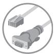
DB9-to-RJ11 Serial Flash Cable

User Manual

Quick Installation Guide
6V DC, 1A Power Supply
Feature Overview
- CAT5 Technology
Integrated CAT5 technology enables you to connect your KVM Switch to your servers up to 100 feet (30m) away using standard CAT5 cabling and Belkin's compact Server Interface Modules. CAT5 cabling reduces wiring clutter, simplifies cable management, and allows for greater airflow in your racks, increasing the lifespan of your equipment. Server Interface Modules enable continuous server uptime using keep-alive intelligence and keyboard and mouse signal emulation.
Dedicated Daisy-Chain Port
Up to 16 KVM switches can be daisy-chained together using dedicated ports, so you can easily expand your KVM configuration as your server environment grows.
Video Resolution
The SMB CAT5 KVM Switch supports video resolutions of up to 1600x1200@75Hz.
- On-Screen Display (OSD)
The OSD feature simplifies server management by allowing you to assign individual names to each connected server throughout the system. It provides a visual means of switching between servers and setting the time interval for the AutoScan function.
Hot Keys
Hot key functionality allows you to select a desired port using designated key commands. By using a simple hot key sequence on your keyboard, you can select one server from as many as 256 servers, instantaneously.
- Front-Panel Push Buttons
Direct-access port selectors, located conveniently on the front panel of the SMB CAT5 KVM Switch, allow for simple, manual port-selection.
AutoScan
The AutoScan feature allows you to set your SMB CAT5 KVM Switch to scan and monitor the activities of all connected servers, one by one. The time interval allotted for each server can be defined or adjusted through the On-Screen Display (OSD) menu.
- LED Display
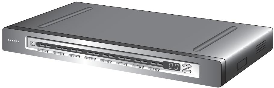
An LED display on the front panel of the SMB CAT5 KVM Switch serves as a status monitor. An LED above each direct-access port selector illuminates to indicate that the console currently controls the corresponding server. As a port selector is pushed, the LED above it will light up. A flashing port LED indicates that there is no server connected to that port.
- Seven-Segment LED Display
When daisy-chaining multiple SMB CAT5 KVM Switches together, the seven-segment LED display serves as a quick indicator of the selected BANK.
- Flash Upgrade
Flash-upgradeable firmware allows you to install the latest firmware for your SMB CAT5 KVM Switch. This enables your KVM Switch to maintain consistent compatibility with the latest devices and servers. Firmware upgrades are free for the life of your SMB CAT5 KVM Switch and can be downloaded from Belkin's support website at www.belkin.com/support.
Equipment Requirements
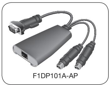
Server Interface Modules
Connecting the SMB CAT5 KVM Switch to a server requires a custom Belkin OmniView SMB Server Interface Module and a standard CAT5 patch cable.
OmniView SMB Server Interface Modules:
F1DP101AeaAP (PS/2 style)
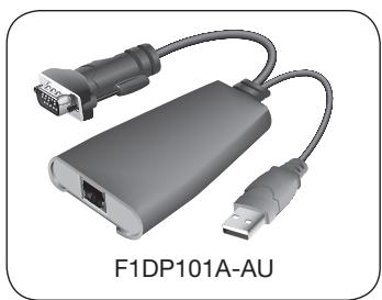
F1DP101AeaAU (USB style)
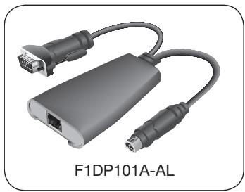
F1DP101AeaAL (Legacy Sun™ miniDIN8 style)
F1DP101AeaAP-8P (PS/2 style, 8-pack)
NOTE: Product codes and availability may vary.
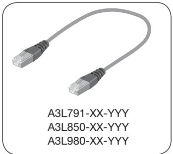
Cables
Belkin highly recommends you use Belkin Category 5e, FastCAT5e, or Category 6 Patch Cables for your SMB CAT5 KVM Switch to help ensure the superior performance of your video. These cables offer the highest quality possible to ensure optimal data and video transmission.
NOTE: Use CAT6 solid cables for optimal video at longer lengths.
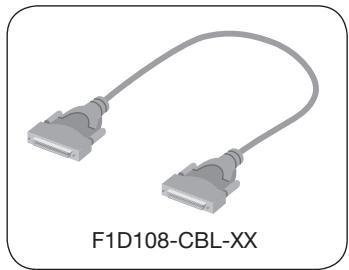
To connect multiple KVM switches together, a custom Belkin OmniView Daisy-Chain cable is required.
Belkin UTP Patch Cables:
A3L791-XX-YYY (CAT5e)
A3L850-XX-YYY (FastCAT5e)
A3L980-XX-YYY (CAT6)
OmniView Daisy-Chain Cable: F1D108-CBL-XX
(-XX denotes length in feet) (-YYY denotes color)
NOTE: Product codes and availability may vary.
System Requirements
OS Platforms
The SMB CAT5 KVM Switch is compatible with CPUs running on, but not limited to, the following OS platforms:
- Windows® NT®, 95, 98, 2000, Me, XP, Server 2003
- Microsoft® DOS 5.x and above
- Red Hat® Linux® 8.x and above
Novell® NetWare 5.x
Mac OS X and above (with USB support)
Solaris 8.x and above
Keyboards
PS/2-compatible
Supports 101-/102-/104-/106-standard-key keyboards
Mice
- PS/2-compatible or PS/2 & USB combo mice (with PS/2 adapter) having 2, 3, 4, or 5 buttons
- PS/2-compatible wireless or optical mice
Monitors
- CRT
- LCD (with VGA support)
Unit Display Diagrams
Front View of the SMB CAT5 KVM Switch:
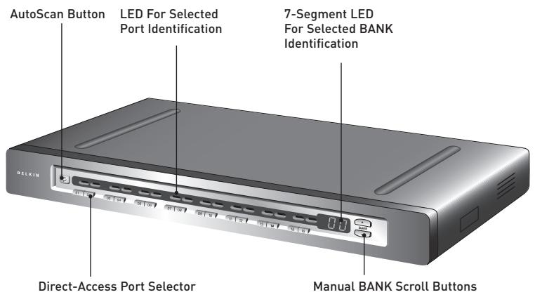
(F1DP116Aea shown)
1
2
3
4
5
6
7
8
Unit Display Diagrams
Back View of the SMB CAT5 KVM Switch:
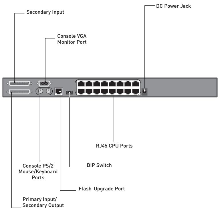
(F1DP116Aea shown)
Specifications
SMB CAT5 KVM Switch
Part No.:
F1DP104Aea, F1DP108Aea, F1DP116Aea
Enclosure:
Metal enclosure with high-impact plastic faceplate
Power:
6-volt DC, 1-Amp power adapter with center-pin positive polarity
Daisy-Chain:
Maximum of 16 OmniView KVM Switches
No. of Servers Supported:
4, 8, 16 respectively for 4-port, 8-port, 16-port models (256 servers max via daisy-chaining)
Console Keyboard Emulation:
PS/2
Console Mouse Emulation:
PS/2
Monitors Supported:
CRT and LCD (with VGA support)
Max. Resolution:
Up to 1600x1200@75Hz
Keyboard Input:
miniDIN6 (PS/2)
Mouse Input:
miniDIN6 (PS/2)
Monitor Port:
HDDB15 female (VGA)
CPU Ports:
RJ45
Daisy-Chain Ports:
DB25 female
Flash-Upgrade Port:
RJ11
Direct Port Selectors:
4, 8, 16 respectively for 4-port, 8-port, 16-port models
Operating Temp:
32^ to 104^ F (0 40^)
Storage Temp:
-4° to 140° F (20~60°C)
Humidity:
0-80% RH, non-condensing
Warranty:
5 years
2
3
4
5
6
7
8
Dimensions:
(F1DP104Aea) 11 x 1.75 x 6 in.
(279mm x 44.5mm x 150mm)
(F1DP108Aea) 17.25 × 1.75 × 7.5 in.
(438mm x 44.5mm x 190mm)
(F1DP116Aea) 17.25 × 3.5 × 7.5 in.
(438mm x 89mm x 190mm)
Weight:
(F1DP104Aea) 5.3 lbs. (2.4kg.)
(F1DP108Aea) 9.2 lbs. (4.2kg.)
(F1DP116Aea) 12.0 lbs. (5.5kg.)
NOTE: Specifications are subject to change without notice.
SMB Server Interface Module, PS/2
Part No.:
F1DP101AeaAP
Emulation:
Keyboard and mouse signals
Power:
Via attached server; with keep-alive intelligence
Keyboard/Mouse Connection:
miniDIN6 (PS/2)
Monitor Connection:
HDDB15 male (VGA)
Resolution Support:
Up to 1600x1200@75Hz
Max. Distance Supported:
100 ft. (30m)
Weight:
0.25 lbs. (0.11kg.)
Unit Dimensions:
2.50 × 3.87 × 1.00 in.
(63.5mm x 98.3mm x 25.4mm)
VGA Cable Length:
8 in. (203mm)
PS/2 Cable Length:
19 in. (483mm)
SMB Server Interface Module, USB
Part No.: F1DP101AeaAU
Emulation: Keyboard and mouse signals
Power: Via attached server; with keep-alive intelligence
Keyboard/Mouse Connection: USB Type A
Monitor Connection: HDDB15 male (VGA)
Resolution Support: Up to 1600x1200@75Hz
Max. Distance Supported: 100 ft. (30m)
Weight: 0.25 lbs. (0.11kg.)
Unit Dimensions: 2.50 × 3.87 × 1.00 in. (63.5mm x 98.3mm x 25.4mm)
VGA Cable Length: 8 in. (203mm)
USB Cable Length: 19 in. (483mm)
SMB Server Interface Module, Legacy Sun
Part No.: F1DP101AeaAL
Emulation: Keyboard and mouse signals
Power: Via attached server; with keep-alive intelligence
Keyboard/Mouse Connection: miniDIN8 (Legacy Sun)
Monitor Connection: HDDB15 male (VGA)
Resolution Support: Up to 1600x1200@75Hz
Max. Distance Supported: 100 ft. (30m)
Weight: 0.25 lbs. (0.11kg.)
Unit Dimensions: 2.50 × 3.87 × 1.00 in. (63.5mm x 98.3mm x 25.4mm)
VGA Cable Length: 8 in. (203mm)
USB Cable Length: 19 in. (483mm)
Pre-Configuration
Where to Place the SMB CAT5 KVM Switch
The enclosure of the SMB CAT5 KVM Switch is designed for standalone or rack-mount configuration. The 8- and 16-port SMB CAT5 KVM Switches are natively rack-mountable in standard 19-inch server racks. Rack-mount hardware is included with these switches for a sturdy rack installation. An optional RackMount Kit (F1D005) is available for use with the 4-Port SMB CAT5 KVM Switch.
Consider the following when deciding where to place the SMB CAT5 KVM Switch:
- whether or not you intend to use the direct-access port selectors
- the lengths of the cables attached to your keyboard, monitor, and mouse
- the location of your servers in relation to your console
- the lengths of the cables you use to connect your servers to the SMB CAT5 KVM Switch
Cable Distance Requirements (for PS/2, USB, and Sun Servers)
VGA signals transmit best up to 100 feet (30m). Beyond that length, the probability of video degradation increases. For this reason, Belkin recommends that the length of the CAT5 UTP cable between the SMB CAT5 KVM Switch and the connected servers does not exceed 100 feet (30m).
NOTE: The Belkin CAT5 Extender (F1D084) may be used to extend your console (keyboard, mouse, and monitor) by up to 500 feet (152m).
WARNING! Avoid placing cables near fluorescent lights, air conditioning equipment, or machines that create electrical noise (e.g., vacuum cleaners).
You are now ready to begin installation of your SMB CAT5 KVM Switch. The following sections (pages 13-22) provide complete instructions for the hardware setup of a single SMB CAT5 KVM Switch (F1DP104A, F1DP108A, F1DP116A).
Note for Belkin PRO2 Series Owners (F1DA104T, F1DA108T, F1DA116T): Installation for the PRO2 KVM Switch has changed. Please follow this installation manual completely to ensure proper installation. Failure to do so may result in keyboard or mouse errors, and/or faulty operation.
Mounting the SMB CAT5 KVM Switch
Bracket Installation (F1DP108Aea and F1DP116Aea)
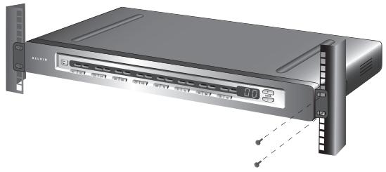
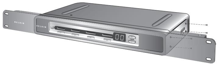
Eight- or 16-Port SMB CAT5 KVM Switches include adjustable mounting brackets ideal for installation in 19-inch racks. The mounting brackets feature three adjustment positions to allow you to set the SMB CAT5 KVM Switch's face flush with the ends of the rails or to extend the SMB CAT5 KVM Switch past the front of the rails. Please follow these simple steps to achieve the desired adjustment.
Step 1
Determine how far you would like the SMB CAT5 KVM Switch to protrude from the rack. Select a bracket-hole scheme.
Step 2
Attach the bracket to the side of your SMB CAT5 KVM Switch using the Phillips screws provided. (Refer to diagram below.)
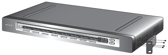
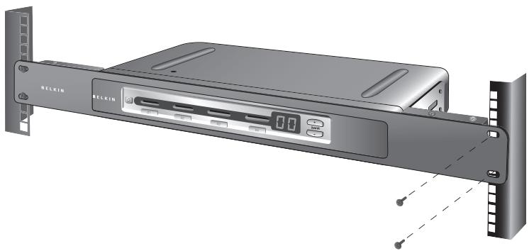
Step 3
Mount the SMB CAT5 KVM Switch to the rack-rail assembly. (Refer to diagram below.)
NOTE: If this SMB CAT5 KVM Switch will be daisy-chained to another KVM switch, set the BANK address prior to installing on a rack. Refer to the section in this User Manual labeled “Connecting Multiple SMB CAT5 KVM Switches (Daisy-Chaining)”.
Your SMB CAT5 KVM Switch is now mounted securely into the bracket and you are ready to connect the console.
Optional Bracket Installation (F1DP104Aea)
The SMB 4-Port CAT5 KVM Switch can be installed into a 19-inch server rack using an optional OmniView Rack-Mount Kit (F1D005).
Step 1
Attach the Rack-Mount Bracket to your SMB CAT5 KVM Switch using the Phillips screws provided. (Refer to diagram below.)
Step 2
Mount the SMB CAT5 KVM Switch to the rack-rail assembly. (Refer to diagram below.)
NOTE: If this SMB CAT5 KVM Switch will be daisy-chained to another KVM switch, set the BANK address prior to installing on a rack. Refer to the section titled “Connecting Multiple SMB CAT5 KVM Switches (Daisy-Chaining)” in this User Manual.
Your SMB CAT5 KVM Switch is now mounted securely to the rack and you are ready to connect the console.
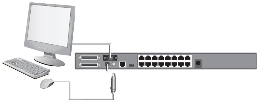
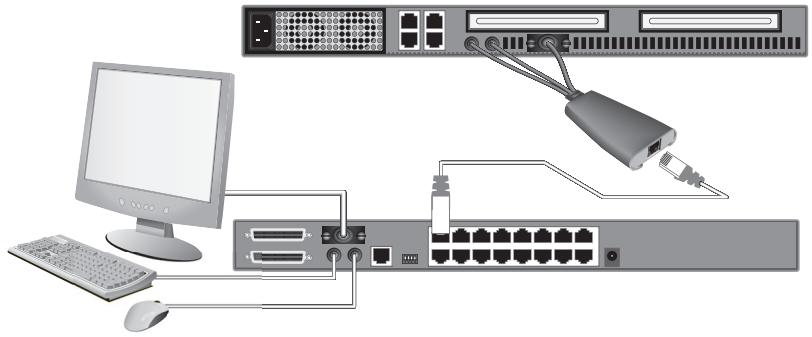
Connecting the Console to the SMB CAT5 KVM Switch
Step 1
Connect the VGA monitor cable to the HDDB15 female port on the back of the SMB CAT5 KVM Switch in the "Console" section. (Refer to diagram below.)
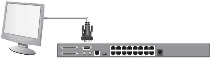
Step 2
Connect the PS/2 keyboard cable to the keyboard port on the back of the SMB CAT5 KVM Switch in the "Console" section. (Refer to diagram below.)
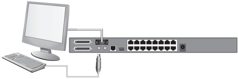
Step 3
Connect the PS/2 mouse cable to the mouse port on the back of the SMB CAT5 KVM Switch in the "Console" section. (Refer to diagram below.)
Step 4
Attach the power adapter to the DC power jack labeled "6VDC, 1A" located on the rear panel of the SMB CAT5 KVM Switch. Only use the power adapter supplied with the unit. (Refer to diagram below.)
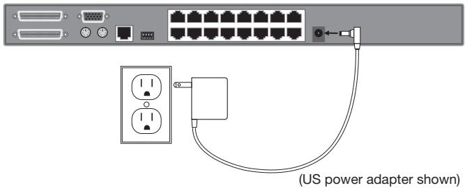
Your SMB CAT5 KVM Switch is now installed and you are ready to connect your servers.
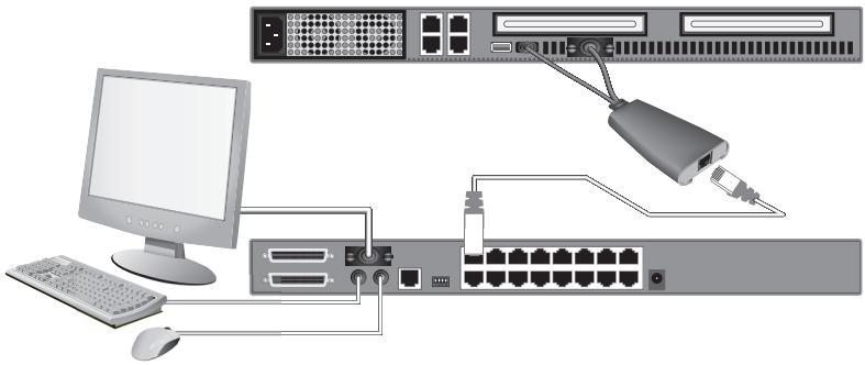
Connecting Servers to the SMB CAT5 KVM Switch (PS/2 Connection):
Step 1
Make sure your server is powered off.
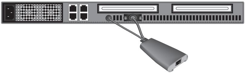
Step 2
Using the Belkin OmniView SMB Server Interface Module for PS/2 (F1DP101AeaAP), connect the VGA connector to the monitor port on your server. (Refer to diagram below.)
Step 3
Connect the PS/2 mouse and then the keyboard connectors to the mouse and keyboard ports on the server. (Refer to diagram below.)
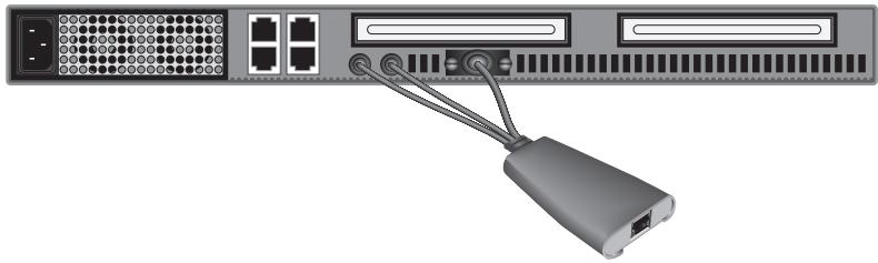
Step 4
Connect the SMB CAT5 KVM Switch to the Server Interface Module using the included Belkin CAT5e Patch Cable or other CAT5 cable. (Refer to diagram below.)
Step 5
Power-up your server.
Step 6
Repeat Steps 1 through 5 for each additional PS/2 server you wish to connect.
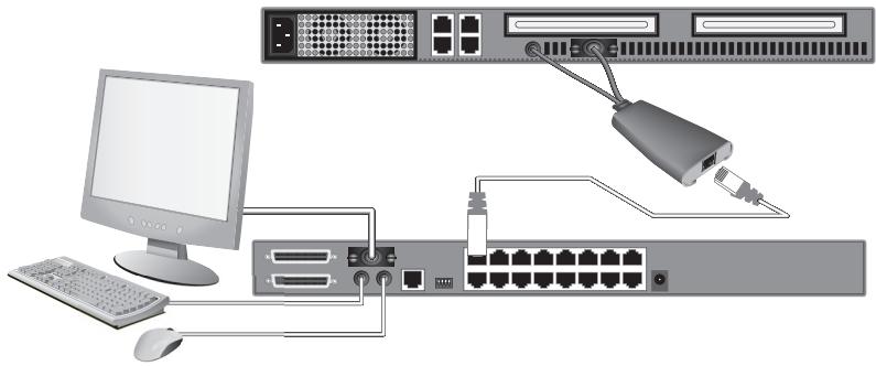
Connecting Servers to the SMB CAT5 KVM Switch (USB Connection):
Step 1
Make sure your server is powered on.
Step 2
Using the Belkin OmniView SMB Server Interface Module for USB (F1DP101AeaAU), connect the VGA connector to the monitor port on your server. (Refer to diagram below.)
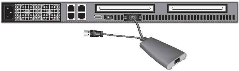
Step 3
Connect the USB connector to an available USB port on the server. (Refer to diagram below.)
1
2
3
4
5
6
7
8
Step 4
Connect the SMB CAT5 KVM Switch to the Server Interface Module using the included Belkin CAT5e Patch Cable or other CAT5 cable. (Refer to diagram below.) Your server should recognize your Server Interface Module and automatically install the HID USB driver if necessary.
Step 5
Repeat Steps 1 through 4 for each additional USB server you wish to connect.
NOTE: We recommend you attach the Server Interface Module cable directly to a free USB port on your server.
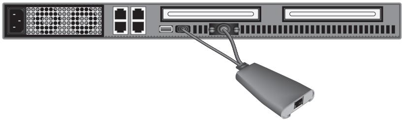
Connecting Servers to the SMB CAT5 KVM Switch (Sun Server with MiniDIN8 Connection):
Step 1
Make sure your server is powered off.
Step 2
Using the Belkin OmniView SMB Server Interface Module for Legacy Sun (F1DP101AeaAL), connect the VGA connector to the monitor port on your server. (Refer to diagram below.)

Step 3
Connect the miniDIN8 connector to the miniDIN8 keyboard port on the server. (Refer to diagram below.)
Step 4
Connect the SMB CAT5 KVM Switch to the Server Interface Module using the included Belkin CAT5e Patch Cable or other CAT5 cable. (Refer to diagram below.)
Step 5
Power-up your server.
Step 6
Repeat Steps 1 through 4 for each additional Sun server you wish to connect.
NOTE: When a USB or Sun Server Interface Module is connected to a Sun server, the Server Interface Module emulates the Sun keys using a set of key combinations called Combo Keys. Refer to the table on page 39 for a list of Sun functions supported by the SMB CAT5 KVM Switch.
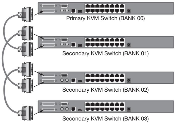
Connecting Multiple SMB CAT5 KVM Switches (Daisy-Chaining)
You can daisy-chain up to 16 SMB CAT5 KVM Switches, allowing a server administrator to manage up to a maximum of 256 servers from one console. Each daisy-chained SMB CAT5 KVM Switch is referred to as a "BANK" and is assigned an address. The SMB CAT5 KVM Switch connected to the console keyboard, mouse, and monitor is BANK 00 and is referred to as the "primary" KVM switch. BANKs 01 through 15 are referred to as "secondary" KVM switches.
NOTE: Your SMB CAT5 KVM Switch is backward-compatible with Belkin OmniView PRO2 KVM Switches. You can daisy-chain any combination of up to 16 SMB CAT5 and PRO2 KVM Switches.
NOTE: A Daisy-Chain Cable (F1D108-CBL) is required to daisy-chain each SMB CAT5 KVM Switch and is available through your Belkin reseller, or online at www.belkin.com (U.S. only).
How to Assign a BANK Address
All SMB CAT5 KVM Switches feature a "BANK DIP" switch. The "BANK DIP" switch is used to assign the proper BANK address to each SMB CAT5 KVM Switch.
- For a single-unit configuration, set the "BANK DIP" switch on the SMB CAT5 KVM Switch to the "primary" (BANK address 00) setting. This is the factory default setting.
- For a multi-unit configuration, the "BANK DIP" switch on the primary KVM switch must be set to "BANK address 00". Each secondary unit must be set to a unique BANK address (from 01 through 15). Refer to the chart on page 24 for "BANK DIP" switch settings.
BANK DIP Switch Configuration Chart
| DIP SWITCH# | BANK ADDRESS | |||
| 1 | 2 | 3 | 4 | |
| Down | Down | Down | Down | |
| Up | Down | Down | Down | BANK 01 Secondary |
| Down | Up | Down | Down | BANK 02 Secondary |
| Up | Up | Down | Down | BANK 03 Secondary |
| Down | Down | Up | Down | BANK 04 Secondary |
| Up | Down | Up | Down | BANK 05 Secondary |
| Down | Up | Up | Down | BANK 06 Secondary |
| Up | Up | Up | Down | BANK 07 Secondary |
| Down | Down | Down | Up | BANK 08 Secondary |
| Up | Down | Down | Up | BANK 09 Secondary |
| Down | Up | Down | Up | BANK 10 Secondary |
| Up | Up | Down | Up | BANK 11 Secondary |
| Down | Down | Up | Up | BANK 12 Secondary |
| Up | Down | Up | Up | BANK 13 Secondary |
| Down | Up | Up | Up | BANK 14 Secondary |
| Up | Up | Up | Up | BANK 15 Secondary |
EXAMPLE:
Four 8-Port SMB CAT5 KVM Switches (F1DP108A) are daisy-chained together to manage up to 32 servers. The DIP switch on the primary KVM switch is set to "BANK 00" (factory default) and the secondary units are each set to a unique BANK (between 01 and 03).
Example of Daisy-Chain Configuration
Getting Started:
Step 1
Make sure that all servers and SMB CAT5 KVM Switches are powered off and that each SMB CAT5 KVM Switch has been assigned a unique BANK address.
Step 2
Place all primary and secondary KVM switches in the desired location.
Step 3
Connect the console monitor, keyboard, and mouse to the console ports of the primary switch (BANK 00). Refer to "Connecting the Console to the SMB CAT5 KVM Switch" on page 15.
Connecting the Primary and Secondary KVM Switches:
Step 1
Using the Daisy-Chain Cable (F1D108-CBL), connect one end to the "Primary Input/Secondary Output" port on the primary KVM switch (BANK 00).
Step 2
Connect the other end of the Daisy-Chain Cable (F1D108-CBL) to the "Primary Input/Secondary Output" port of the first secondary KVM switch (BANK 01).
Step 3
To add additional secondary units, connect one end of the Daisy-Chain Cable (F1D108-CBL) to the "Secondary Input" on the first secondary KVM switch and the other end to the "Primary Input/Secondary Output" port of the next secondary KVM switch (for example, BANK 01).
Step 4
Repeat Step 3 for additional SMB CAT5 KVM Switches you wish to daisy-chain together.
NOTE: When daisy-chaining SMB CAT5 and PRO2 KVM Switches together, be sure to set the PRO2 KVM Switches as secondary switches only.
Connecting the Servers:
Step 1
Connect all servers to the primary and secondary KVM switches. Refer to the "Connecting Servers to the SMB CAT5 KVM Switch" section on page 17 for instructions.
Step 2
Make sure that the power adapter is connected to the primary KVM switch and that the KVM switch is powered on. You should see the primary KVM switch light up and display the digits "00", indicating its BANK address.
Step 3
Power up the secondary KVM switches sequentially, beginning with BANK 01, by connecting each unit's power supply. Each KVM switch should display its corresponding BANK address number as it is powered up.
NOTE: If the SMB CAT5 KVM Switches do not enumerate correctly, reset the primary KVM switch (BANK 00) by simultaneously pressing the “BANK +” and “BANK -” buttons. You can also reset the primary KVM switch to detect newly added secondary KVM switches. If the KVM switches still do not enumerate correctly, check that all KVM switches have the correct BANK address assigned to them and that all daisy-chain cables are connected properly.
Step 4
Verify that the primary KVM switch has detected all secondary KVM switches by scrolling through the BANKS using the "BANK +" and "BANK -" buttons. If all secondary KVM switches are detected properly, the LED display on the primary KVM switch will register and display the BANK address of the attached secondary KVM switch.
Powering Up the Systems
Verify that all servers connected to the SMB CAT5 KVM Switch are powered on. If any connected servers have not been powered on, it is okay to do so at this time (servers can be powered on simultaneously). The SMB CAT5 KVM Switch emulates both a mouse and keyboard on each port and allows your server to boot normally.
The server connected to Port "1" will be displayed on the monitor. Check that the keyboard, monitor, and mouse are working normally. Check all occupied ports to verify that all servers are connected and responding correctly. If you encounter an error, check your cable connections for that server and reboot. If the problem persists, please refer to the "Troubleshooting" section in this User Manual.
Now that you have connected your console and servers to your SMB CAT5 KVM Switch, it is ready for use. Select connected servers by either the direct-access port selectors, located on the front panel of the SMB CAT5 KVM Switch, using the On-Screen Display, or by using hot key commands through the console keyboard. It takes approximately 1-2 seconds for the video signal to refresh after switching servers. Re-synchronization of the mouse and keyboard signals also occurs. This is normal operation and ensures that proper synchronization is established between the console and the connected servers.
Selecting a Server or BANK Using Hot Key Commands
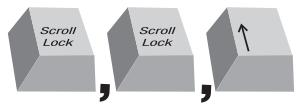
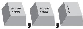
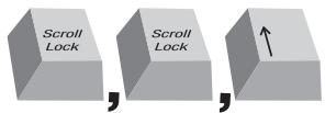
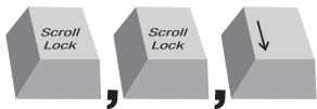
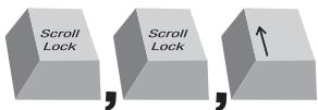
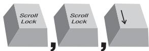
Switch to the next or previous port with simple keyboard hot key sequences using the "Scroll Lock" key and either the "Up" or "Down" arrow keys. To send commands to the SMB CAT5 KVM Switch, the "Scroll Lock" key must be pressed twice within two seconds. The SMB CAT5 KVM Switch will beep, confirming that it is in hot key mode. Next, press the "Up" arrow key and the SMB CAT5 KVM Switch will switch to the next port. Press the "Down" arrow key to switch to the previous port. (Refer to diagram below.)
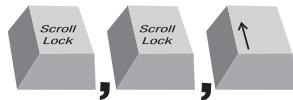
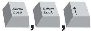
Switch to next active port, "Up" arrow.
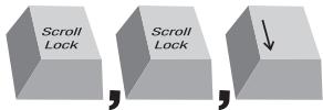
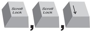
Switch to previous active port, "Down" arrow
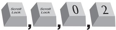
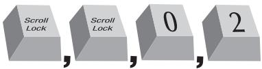
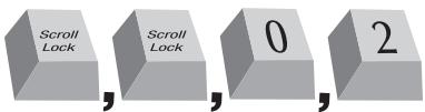
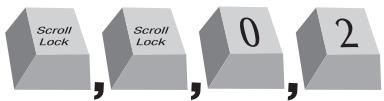
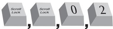
With a single-switch configuration (no daisy-chained KVM switches), you can switch directly to any port by entering the two-digit number of the port you wish to access. For example, if you press "Scroll Lock", "Scroll Lock", "02", the SMB CAT5 KVM Switch will switch to the server on Port 2 located on BANK 00. (Refer to diagram below.)
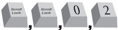
Switch to BANK 00, Port 2 (02)
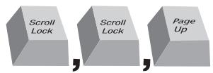
With a daisy-chain switch configuration, you can switch between BANKs (KVM switches) by pressing "Scroll Lock", "Scroll Lock", "Page Up", to switch to the previous BANK. Press "Scroll Lock", "Scroll Lock", "Page Down", to switch to the next BANK. (Refer to diagram below.)

With a daisy-chain switch configuration, you can switch directly to any port on any BANK by pressing "Scroll Lock", "Scroll Lock", BANK address, and Port Number. For example, if you press "Scroll Lock", "Scroll Lock", "03", "05", the server on BANK 03, Port 5 will become active. (Refer to diagram below.)
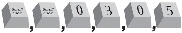
NOTE: You will have approximately five seconds to complete each hot key sequence.
See page 36 for instructions on how to change the hot key initiator key.
Selecting a Server Using Direct-Access Port Selectors
You can directly select which server you wish to control by pressing the direct-access port selector next to the corresponding port. The LED will illuminate to indicate the port is currently selected. If you are installing multiple SMB CAT5 KVM Switches that are daisy-chained, use the BANK scroll keys located on the front panel of the primary KVM switch to access other servers that are connected to the secondary KVM switches.
Selecting a BANK Using Scroll Buttons
Pressing the "BANK +" and "BANK -" scroll buttons on the primary KVM switch will allow you to switch between the daisy-chained SMB CAT5 KVM Switches. Pressing both buttons simultaneously will reset the SMB CAT5 KVM Switch.
The "BANK +" button will take you to the next BANK. For example, when you are at the primary switch (BANK 00) and want to check servers on BANK 02, pressing the "BANK +" button will take you to BANK 02. As a default, the first active server will be displayed on the console monitor. Use the direct-access port selectors to go to the desired server on BANK 02.
The "BANK -" button will take you to the previous BANK (for example, when you are at BANK 02 and want to check servers in BANK 01). Pressing the "BANK -" button will take you to BANK 01. As a default, the first active server will be displayed on the console monitor. Use the direct-access port selectors to go to the desired server on BANK 01.
AutoScan Mode
The AutoScan feature allows you to set your SMB CAT5 KVM Switch to scan and monitor the activities of all connected servers one by one. The SMB CAT5 KVM Switch remains on one server for a preset number of seconds, before switching to the next server. The time interval allotted for each server can be defined or adjusted through the OSD menu (see the "Scan Time" section).
When the SMB CAT5 KVM Switch is in AutoScan mode, it is also in View-Only mode. This means that input from the console (keyboard and mouse) will not be transmitted to the server in focus. Cancel AutoScan to regain control of the server.
To activate the AutoScan function, press the AutoScan button on the SMB CAT5 KVM Switch. You can also activate AutoScan on your keyboard by pressing "Scroll Lock", "Scroll Lock", space bar, "F4".
To disable AutoScan, press any button on the front panel or any key on the keyboard.
NOTE: There is no mouse or keyboard control in AutoScan mode. This is necessary to prevent data and synchronization errors. If the user is using the mouse or keyboard when the SMB CAT5 KVM Switch is switching between ports, data flow may become interrupted and could result in erratic mouse movement and/or wrong-character input when using the keyboard.
ON-SCREEN Display
The On-Screen Display allows you to switch servers, assign names to your servers, enable and disable the AutoScan feature, set the desired scan time interval for AutoScan, enable the password security feature, and program hot keys. To access the On-Screen Display (OSD) menu, press "Scroll Lock", "Scroll Lock", and the space bar. Immediately, the OSD overlay screen will appear. The superimposed menu screen is generated by the SMB CAT5 KVM Switch, and does not affect the function of your server, operating system, or software function.
Main OSD Menu Page
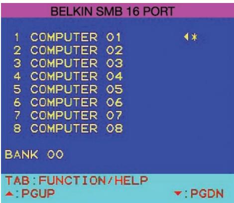
The main OSD menu displays the current selected BANK and connected servers to that BANK. If you have only one SMB CAT5 KVM Switch in your configuration, the OSD menu will display "BANK 00". A "" symbol indicates that the connected server is powered up. If the OSD menu does not display a "" symbol for a server that is connected and powered up, you will need to reset the SMB CAT5 KVM Switch to re-detect the server. This is done by simultaneously pressing the "BANK +" and "BANK -" buttons on the front panel.
OSD Menu Keyboard Commands
| (↓↑) | Navigate to different servers in the same BANK |
| (Page Up/Page Down) | Select next or previous BANK |
| (Insert) | Highlight server name for editing |
| (Enter) | Switch servers |
| (Tab) | Open the “Function/Help” page |
| (Esc) | Exit the On-Screen Display |
To switch servers using the main OSD menu, use the arrow keys on your keyboard to navigate to the desired server and press the "ENTER" key. A “ ” symbol indicates which server is currently being accessed on your console. To select a different BANK, press the "Page Up" or "Page Down" key to select the next BANK or the previous BANK. To change the name of a server, use the arrow keys to navigate to the desired server, press the "Insert" key, type in the new name, and press "ENTER" to save the entry. You may use up to 15 characters for each server name. To open the "Setup" page, press the "Tab" key. To exit the On-Screen Display, press the "ESC" key.
Function/Help Page
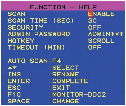
The "Function/Help" page allows you to set the time intervals for the AutoScan feature and OSD display time, enable the password security feature, and program hot keys.
Function/Help Page Keyboard Commands
| (F4) | Initiate AutoScan |
| (↓↑) | Navigate to the next field |
| (Insert) | Highlight field for editing |
| (Esc) | Return to the main OSD menu |
| (F10) | Program Monitor-DDC2 settings to all Server Interface Modules |
| (Space) | Change options for selected field |
Scan
This specifies whether the AutoScan feature is enabled or not. To enable or disable the AutoScan feature, use the arrow keys to navigate to the "Scan" field and press the space bar.
Scan Time
This specifies the amount of time the SMB CAT5 KVM Switch remains on a server before switching to the next server while in AutoScan mode. You may set the scan time interval to anywhere between 5 and 99 seconds. To change the scan time, use the arrow keys to navigate to the Scan Time field, type the desired time interval (in seconds).
Security
This feature allows you to enable an administrator password to prevent unauthorized users from accessing the OSD. To enable or disable the Security feature, use the arrow keys to navigate to the "Security" field and press the space bar.
Admin Password
This allows you to specify the administrator password needed to access the OSD when the Security feature is enabled. To set the password, use the arrow keys to navigate to the "Admin Password" field and type in the desired password. You may use up to eight uppercase characters for the password. Password characters are not case-sensitive. Press "Esc" or use the arrow keys to navigate to fields and save the password. Use the "Back Space" key to erase the password.
Hot Key
This allows you to select which key will be used to initiate hot key commands. You have four options to choose from: "Scroll Lock", "Print Screen", "Left Ctrl", and "F12". The default key for all hot key commands is "Scroll Lock" (see "Keyboard Hot Key Command Shortcuts below). To designate a different key to initiate hot key commands, use the arrow keys to navigate to the "Hot Key" field, press the space bar until the preferred key is found, and press "Enter" to save the entry.
Timeout
This specifies the amount of time that can elapse before the administrator will be locked out of the KVM Switch (and connected servers) due to user inactivity. To regain access to the KVM Switch after Timeout, simply reenter the Admin Password in the login box. The Timeout feature is only available if the Security feature is enabled. You may set the time intervals to anywhere between 1 and 99 minutes. To change the time interval, use the arrow keys to navigate, type the desired time interval, and press "Enter" to save the entry. If you disable the Security feature, the Timeout feature will be turned off automatically.
NOTE: If there are secondary KVM switches connected, and the AutoScan time and Timeout settings are set on the primary KVM switch, the settings will also apply to all secondary KVM switches.
Monitor-DDC2 Feature
This feature allows the console monitor to inform the server's video card about its properties, such as maximum resolution and color depth. The video card will then adjust the monitor's settings accordingly. This enables your monitor to use its optimal settings for every server connected to your SMB CAT5 KVM Switch. To read the DDC2 information from the monitor and program it to all connected Server Interface Modules, press "F10". Every time you change the monitor, you will need to press "F10" again to program the new DDC information to the Server Interface Modules.
Keyboard Hot Key Command Shortcuts
Below is a complete list of hot key commands that can be used for your SMB CAT5 KVM Switch:
| SL, SL, Up Arrow | Switch to PREVIOUS ACTIVE port |
| SL, SL, Down Arrow | Switch to NEXT ACTIVE port |
| SL, SL, Page Up | Switch to PREVIOUS BANK (By default, selects first active port on the BANK) |
| SL, SL, Page Down | Switch to NEXT BANK (By default, selects first active port on the BANK) |
| SL, SL, Y | Directly switches to PORT Y on BANK 00 (Single-Switch Configuration) Y=01 to 16 |
| SL, SL, X, Y | Directly switches to PORT Y on BANK X (Daisy-Chain Configuration) (X=00 to 15) (Y=01 to 04 for F1DA104T) (X=00 to 15) (Y=01 to 08 for F1DA108T) (X=00 to 15) (Y=01 to 16 for F1DA116T) |
| SL, SL, Space Bar, F10 | Monitor DDC2 (identifies monitor settings) |
| SL, SL, Space Bar | Activate On-Screen Display |
| SL, SL, F4 | Enable AutoScan mode (refer to AutoScan button) |
NOTE: You will have approximately five seconds to complete each hot key sequence.
Sun Combo Keys
The PS/2 keyboard connected to the SMB CAT5 KVM Switch does not support the Sun keypad to perform special functions in the Sun operating system environment. When a USB or Sun Server Interface Module is connected to a Sun server, the Server Interface Module emulates the Sun keys using a set of key combinations called Combo Keys. Please refer to the table below.
| Sun Key | Combo Key |
| Stop | Left Ctrl + Alt + F1 |
| Props | Left Ctrl + Alt + F3 |
| Front | Left Ctrl + Alt + F5 |
| Open | Left Ctrl + Alt +F7 |
| Find | Left Ctrl + Alt + F9 |
| Again | Left Ctrl + Alt + F2 |
| Undo | Left Ctrl + Alt + F4 |
| Copy | Left Ctrl + Alt + F6 |
| Paste | Left Ctrl + Alt + F8 |
| Cut | Left Ctrl + Alt + F10 |
| Help | Left Ctrl + Alt + F11 |
| Compose | Application key or Left Ctrl + Alt + keypad * |
| Crescent | Scroll Lock |
| Volume Up | Left Ctrl + Alt + keypad - |
| Volume Down | Left Ctrl + Alt + keypad + |
| Mute | Left Ctrl + Alt + F12 |
| Sun Left◇Key | Left Windows key |
| Sun Right◇Key | Right Windows key |
| Alt-Graph | Right Alt or Alt Gr |
| Stop A | Left Ctrl + Alt +1 |
Updating Firmware
The SMB CAT5 KVM Switch features flash-upgradeable firmware to ensure compatibility with the latest devices and servers. Firmware upgrades are free for the life of your SMB CAT5 KVM Switch.
To update your firmware, download the appropriate firmware file and utility from www.belkin.com/support/. The utility will guide you through the process of updating the firmware on your SMB CAT5 KVM Switch.
WARNING! We strongly recommend that you update your firmware only if you are experiencing mouse and keyboard problems with your SMB CAT5 KVM Switch, as reconfiguring software may lead to unexpected operational problems. Please contact Belkin Technical Support if you need assistance.
To update the firmware, you will need the following items:
- A separate server running Windows 2000 or XP. This server must not be connected to the server ports on the SMB CAT5 KVM Switch.
- An available serial port on the server.
- A custom Serial Flash Cable (DB9 male-to-RJ11; included with purchase) that connects between the SMB CAT5 KVM Switch and the server.
What operating systems does the SMB CAT5 KVM Switch support?
The SMB CAT5 KVM Switch will support any operating system that runs on a PS/2 and USB platform. Operating systems include, but are not limited to, DOS, Windows 95/98/2000/Me/NT/XP/2003 Server, Sun, Linux, and Mac OS.
What does flash-upgradeable mean?
With flash-upgrade capability, you can update your SMB CAT5 KVM Switch firmware at any time through a simple serial connection. Upgrade capability ensures that your SMB CAT5 KVM Switch is always the most current version on the market with the latest features and enhancements. See the "Updating Firmware" section in this User Manual on page 40 for more information.
Does the SMB CAT5 KVM Switch support Microsoft IntelliMouse?
The SMB CAT5 KVM Switch supports mice from Microsoft, Logitech®, Kensington®, etc., and Belkin. Please contact Belkin Technical Support for compatibility issues you may experience.
How does the SMB CAT5 KVM Switch allow the user to switch between ports?
The SMB CAT5 KVM Switch supports three methods of port selection. The user can select servers using specially designated keyboard hot keys, through the On-Screen Display, or can independently access the desired port by pushing the direct-access port selectors
How far can the server be from the SMB CAT5 KVM Switch?
The SMB CAT5 KVM Switch can be placed up to 100 feet (30m) away from your server.
What is the maximum video resolution that the SMB CAT5 KVM Switch supports?
The advanced video circuit in the SMB CAT5 KVM Switch supports a maximum resolution of up to 1600x1200@75Hz. Increasing the cable length from your SMB CAT5 KVM Switch to your servers will result in lower resolution support.
Do I have to install any software to use the SMB CAT5 KVM Switch?
No, the SMB CAT5 KVM Switch does not require any drivers or software to be installed in your servers. Simply connect all your servers to the SMB CAT5 KVM Switch using Server Interface Modules, and then attach one keyboard, monitor, and mouse to the console port and it is ready for use.
Does the SMB CAT5 KVM Switch require an AC adapter?
Yes, the SMB CAT5 KVM Switch requires a 5-volt DC, 1-Amp power adapter in order to function properly.
Can I use the SMB CAT5 KVM Switch to switch video signals only?
No, the Server Interface Modules must be connected to both the video and keyboard/mouse ports on your servers. The Server Interface Modules require power from the PS/2, USB, or Sun miniDIN8 ports on your servers in order to function.
Can I use the SMB CAT5 KVM Switch on my Sun server that supports USB?
Yes, the SMB CAT5 KVM Switch works with any USB-capable server.
Does the SMB CAT5 KVM Switch support Linux?
A: Yes, the SMB CAT5 KVM Switch works with Red Hat® and other Linux distributions configured for PS/2 or USB support.
How long is the warranty for the SMB CAT5 KVM Switch?
The SMB CAT5 KVM Switch comes with a Five-Year Limited Warranty.
My server does not boot when connected to the SMB CAT5 KVM Switch but works fine when I connect the keyboard, video, and mouse directly to the server.
- Make sure that the keyboard and mouse cables are connected tightly between the Server Interface Module and the server.
- Check that the keyboard and mouse cables are not crossed.
- Check the CAT5 cable connection.
I am getting ghosting, shadowing, or fuzzy images on my monitor.
- Check that all video cables are inserted properly to the Server Interface Module.
- Check that the monitor you are using supports the resolution and refresh-rate setting on your server.
- Lower the video resolution of your monitor.
- Check that the cable length does not exceed 100 feet (30m).
- Check that the graphics card you are using supports the resolution and refresh-rate setting on your server.
- Connect the monitor directly into the server you are having trouble with to see if the problem still appears.
I am getting a black screen on my monitor.
- Check that all video cables are inserted properly.
- Check that the keyboard cable is connected and inserted properly between the server and the Server Interface Module for the appropriate port.
- Connect your monitor directly to the server to verify that your monitor is functioning properly.
The server does not detect a keyboard and I get a keyboard error reported at boot-up.
- Check that the keyboard cable on the Server Interface Module is completely connected to your server. Tighten any loose connections.
- If you are using the keyboard software that was included with your keyboard, uninstall it and then reinstall the standard Microsoft keyboard driver.
The mouse is lost when I switch to a different port.
- Check that the mouse you are using is connected properly to the console port of the SMB CAT5 KVM Switch.
- Check that the mouse cable on the Server Interface Module is completely connected to your server. Tighten any loose connections.
- If you are using a mouse driver that was included with your mouse, uninstall it and install the standard Microsoft mouse driver.
- Make sure the mouse works when directly plugged into the server.
- If the server is coming out of standby mode, allow up to one minute to regain mouse function.
- De-activate power-management schemes on the PC with which you are experiencing problems.
Try a different mouse.
The mouse is not detected at boot-up.
- Check the cables and make sure that they are inserted correctly.
The server boots up, but the mouse does not work.
- Make sure the mouse is plugged in properly.
- Make sure the mouse works when directly plugged into the server. Rebooting may be necessary when trying this.
- Try a different mouse.
When I switch from one port to another, mouse movement is completely erratic.
- Make sure you do not have more than one mouse driver installed. Make sure that the driver is either for a standard PS/2 mouse or a Microsoft server-compatible PS/2 mouse.
- Make sure you do not have any mouse drivers loaded in your "CONFIG.SYS" or "AUTOEXEC.BAT" files.
- Avoid moving the mouse or pressing the mouse button when switching ports on the SMB CAT5 KVM Switch.
- Stop moving the mouse, wait for five seconds, and then move the mouse again. The Server Interface Module will synchronize the mouse movement automatically.
USB
I am connecting the USB Server Interface Module to my USB server and my keyboard and mouse do not work.
- Prior to connecting the USB Server Interface Module, make sure that the HID USB driver is installed on each server. (To install the HID USB driver, connect a USB mouse and USB keyboard to the server. A Windows operating system should automatically install the drivers.)
Some of the keys on my keyboard are not functioning properly when I use a Mac® server.
- If you are using a PC keyboard on a Mac system, a few of the option keys on your PC keyboard may be reversed. All major keys will function as labeled.
The following definitions are used throughout this User Manual:
AutoScan: A mode of operation where the KVM switch scans from one port to another, on an ongoing basis, as configured by the user.
BANK: The address of a daisy-chained KVM switch (00-15), set by the DIP switch.
Console: The all-in-one term for the keyboard, video monitor, and mouse connected to a KVM switch.
Console Port: Receptors for the console to connect to the KVM switch.
Control: When discussing switching between ports, control means that the console is capable of sending input to the server. Control requires that the console also has focus on the port, and is viewing it.
Daisy-Chain: A configuration of multiple KVM switches that are connected one to another in a series. A KVM switch daisy-chain uses common settings to allow seamless, complex interactions between multiple consoles for control over many servers.
DDC: Short for Display Data Channel, a VESA standard for communication between a monitor and a video adapter. Using DDC, a monitor can inform a computer's video card about its properties, such as maximum resolution and color depth, to ensure that the user is presented with valid options for configuring the display.
HID: Human Interface Device, the USB device class that includes keyboards and mice.
KVM: Literally "Keyboard Video Mouse", this term refers to technology that allows two or more computers to be controlled by one keyboard, video monitor, and mouse; some switches that use KVM technology enable sharing of other peripherals such as audio speakers, microphones, and printers.
KVM Switch: A device that allows a user to access and control multiple servers from a single console. It has at least one console port and multiple server ports.
OSD: On-Screen Display, a Graphical User Interface that can be used to control and configure the KVM Switch.
Port: An interface receptor on a server through which you can attach a device or plug in a device cable.
Primary KVM Switch: The KVM switch that is connected to the console and is set to BANK address 00.
Secondary KVM Switch: Any KVM switch that is daisy-chained to the primary KVM switch and is set to BANK address 01-15 (and has no console connected).
FCC Statement
Declaration of Conformity with FCC Rules for Electromagnetic Compatibility
We, Belkin Corporation, of 501 West Walnut Street, Compton, CA 90220, declare under our sole responsibility that the products:
F1DP104A, F1DP108A, F1DP116A,
to which this declaration relates:
Comply with Part 15 of the FCC Rules. Operation is subject to the following two conditions: (1) this device may not cause harmful interference, and (2) this device must accept any interference received, including interference that may cause undesired operation.
CE Declaration of Conformity
We, Belkin Corporation, declare under our sole responsibility that the products F1DP104A, F1DP108A, F1DP116A, to which this declaration relates, are in conformity with Emissions Standard EN55022 and with Immunity Standard EN55024, LVP EN61000-3-2, and EN61000-3-3.
ICES
Belkin Corporation Limited Five-Year Product Warranty
Belkin Corporation warrants this product against defects in materials and workmanship for its warranty period. If a defect is discovered, Belkin will, at its option, repair or replace the product at no charge provided it is returned during the warranty period, with transportation charges prepaid, to the authorized Belkin dealer from whom you purchased the product. Proof of purchase may be required. This warranty does not apply if the product has been damaged by accident, abuse, misuse, or misapplication; if the product has been modified without the written permission of Belkin; or if any Belkin serial number has been removed or defaced.
THE WARRANTY AND REMEDIES SET FORTH ABOVE ARE EXCLUSIVE IN LIEU OF ALL OTHERS, WHETHER ORAL OR WRITTEN, EXPRESSED OR IMplied. BELKIN SPECIFICALLY DISCLAIMS ANY AND ALL IMPLIED WARRANTYES, INCLUDING, WITHOUT LIMITATION, WARRANTYES OF MERCHANTABILITY AND FITNESS FOR A PARTICULAR PURPOSE.
No Belkin dealer, agent, or employee is authorized to make any modification, extension, or addition to this warranty.
BELKIN IS NOT RESPONSIBLE FOR SPECIAL, INCIDENTAL, OR CONSEQUENTIAL DAMAGES RESULTING FROM ANY BREACH OF WARRANTY, OR UNDER ANY OTHER LEGAL THEORY, INCLUDING BUT NOT LIMITED TO, LOST PROFITS, DOWNTIME, GOODWILL, DAMAGE TO OR REPROGRAMMING, OR REPRODUCING ANY PROGRAM OR DATA STORED IN OR USED WITH BELKIN PRODUCTS.
Some states do not allow the exclusion or limitation of incidental or consequential damages or exclusions of implied warranties, so the above limitations or exclusions may not apply to you. This warranty gives you specific legal rights, and you may also have other rights that vary from state to state.

Express Business Park, Shipton Way
Assistance Technique Belkin
Europe:0080022355460
Belkin GmbH
Hanebergstraße 2
Switch to next active port, "Up" arrow.
Switch to previous active port, "Down" arrow
Switch to BANK 00, Port 2 (02)
Express Business Park, Shipton Way
Switch to next active port, "Up" arrow.
Switch to previous active port, "Down" arrow
Switch to BANK 00, Port 2 (02)
Express Business Park, Shipton Way
Rushden, NN10 6GL, Groot-Brittanniè
+44 (0) 1933 35 2000
+44 (0) 1933 31 2000 fax
Belkin B.V.
Boeing Avenue 333
Switch to next active port, "Up" arrow.
Switch to previous active port, "Down" arrow
Switch to BANK 00, Port 2 (02)
Bij daisychainconfigurationskestuarradervorigeBANKoverschakelenmet behulp van de toetsencombatie“ScrollLock”,“ScrollLock”,“PageUp”.U schakeltnarraderolgendeBANKover metde toetscombatinie“ScrollLock”,“ScrollLock”,“PageDown”.(Ziedonderstaandeafbeelding.)


Express Business Park, Shipton Way
Rushden, NN10 6GL, Reino Unido
+44 (0) 1933 35 2000
+44 (0) 1933 31 2000 fax
Belkin B.V.
Boeing Avenue 333
1119 PH Schiphol-Rijk, Paises Bajos
+31 (0) 206547300
+31 (0) 20 654 7349 fax
Asistencia的技术e de Belkin
Europa: 00 800 223 55 460
Belkin GmbH
Hanebergstrasse 2
Conmutar a BANK 00, Puerto 2 [02]
Express Business Park, Shipton Way
fino a 1600x1200@75Hz
fino a 1600x1200@75Hz
Switch to next active port, "Up" arrow.
Switch to previous active port, "Down" arrow
Switch to BANK 00, Port 2 [02]
- Manage your servers using one PS/2 console and CAT5 cabling
- User Manual · Manuel de l'utilisateur Benutzerhandbuch · Handleiding Manual del usuario · Manuale utente
- BELKIN
- Package Contents
- Feature Overview
- - CAT5 Technology
- Dedicated Daisy-Chain Port
- Video Resolution
- - On-Screen Display (OSD)
- Hot Keys
- - Front-Panel Push Buttons
- AutoScan
- - LED Display
- - Seven-Segment LED Display
- - Flash Upgrade
- Equipment Requirements
- Server Interface Modules
- OmniView SMB Server Interface Modules:
- Cables
- Belkin UTP Patch Cables:
- System Requirements
- OS Platforms
- Keyboards
- Mice
- Monitors
- Unit Display Diagrams
- Specifications
- SMB CAT5 KVM Switch
- Dimensions:
- Weight:
- SMB Server Interface Module, PS/2
- Part No.:
- Emulation:
- Power:
- Keyboard/Mouse Connection:
- Monitor Connection:
- Resolution Support:
- Max. Distance Supported:
- Unit Dimensions:
- VGA Cable Length:
- PS/2 Cable Length:
- SMB Server Interface Module, USB
- SMB Server Interface Module, Legacy Sun
- Pre-Configuration
- Where to Place the SMB CAT5 KVM Switch
- Consider the following when deciding where to place the SMB CAT5 KVM Switch:
- Cable Distance Requirements (for PS/2, USB, and Sun Servers)
- Mounting the SMB CAT5 KVM Switch
- Bracket Installation (F1DP108Aea and F1DP116Aea)
- Step 1
- Step 2
- Step 3
- Optional Bracket Installation (F1DP104Aea)
- Connecting the Console to the SMB CAT5 KVM Switch
- Step 4
- Connecting Servers to the SMB CAT5 KVM Switch (PS/2 Connection):
- Step 5
- Step 6
- Connecting Servers to the SMB CAT5 KVM Switch (USB Connection):
- Connecting Servers to the SMB CAT5 KVM Switch (Sun Server with MiniDIN8 Connection):
- Connecting Multiple SMB CAT5 KVM Switches (Daisy-Chaining)
- How to Assign a BANK Address
- EXAMPLE:
- Example of Daisy-Chain Configuration
- Getting Started:
- Connecting the Primary and Secondary KVM Switches:
- Connecting the Servers:
- Powering Up the Systems
- Selecting a Server or BANK Using Hot Key Commands
- Selecting a Server Using Direct-Access Port Selectors
- Selecting a BANK Using Scroll Buttons
- AutoScan Mode
- ON-SCREEN Display
- Main OSD Menu Page
- OSD Menu Keyboard Commands
- Function/Help Page
- Function/Help Page Keyboard Commands
- Scan
- Scan Time
- Security
- Admin Password
- Hot Key
- Timeout
- Monitor-DDC2 Feature
- Keyboard Hot Key Command Shortcuts
- Sun Combo Keys
- Updating Firmware
- To update the firmware, you will need the following items:
- What operating systems does the SMB CAT5 KVM Switch support?
- What does flash-upgradeable mean?
- Does the SMB CAT5 KVM Switch support Microsoft IntelliMouse?
- How does the SMB CAT5 KVM Switch allow the user to switch between ports?
- How far can the server be from the SMB CAT5 KVM Switch?
- What is the maximum video resolution that the SMB CAT5 KVM Switch supports?
- Do I have to install any software to use the SMB CAT5 KVM Switch?
- Does the SMB CAT5 KVM Switch require an AC adapter?
- Can I use the SMB CAT5 KVM Switch to switch video signals only?
- Can I use the SMB CAT5 KVM Switch on my Sun server that supports USB?
- Does the SMB CAT5 KVM Switch support Linux?
- How long is the warranty for the SMB CAT5 KVM Switch?
- The server does not detect a keyboard and I get a keyboard error reported at boot-up.
- The mouse is lost when I switch to a different port.
- The mouse is not detected at boot-up.
- The server boots up, but the mouse does not work.
- When I switch from one port to another, mouse movement is completely erratic.
- USB
- The following definitions are used throughout this User Manual:
- FCC Statement
- Declaration of Conformity with FCC Rules for Electromagnetic Compatibility
- CE Declaration of Conformity
- ICES
- Belkin Corporation Limited Five-Year Product Warranty
Brand : BELKIN
Model : SWITCH KVM CAT5 SMB #F1DP108AEA
Category : KVM Switch