
SEZ-KD50VAL - Air-conditioner MITSUBISHI - Free user manual and instructions
Find the device manual for free SEZ-KD50VAL MITSUBISHI in PDF.

| Brand | MITSUBISHI |
| Model | SEZ-KD50VAL |
| Product type | Split air conditioner (indoor unit) |
| Installation type | Suspended ceiling |
| Dimensions (L x W x H) | 952 x 625 x 280 mm |
| Indoor unit weight | 24 kg |
| Power supply | 230 V, 50 Hz, single-phase |
| Recommended circuit breaker capacity | 20 A |
| Refrigerant type | R410A |
| Main functions | Cooling, heating, dehumidification, ventilation |
| Remote control | Wireless included with receiver |
| Air filter | Washable, accessible from below |
| Maintenance | Regular filter cleaning (adjustable interval 100 h or 2500 h) |
| Safety | Residual current circuit breaker, grounding, automatic shutdown |
| Automatic restart function | Yes |
| External static pressure | Adjustable (15, 35, 50 Pa) |
| Filter indicator | Yes, adjustable |
| Piping connection | Flare, liquid 6.35 mm, gas 12.7 mm |
| Manual | 128 pages, multilingual |
Frequently Asked Questions - SEZ-KD50VAL MITSUBISHI
User questions about SEZ-KD50VAL MITSUBISHI
0 question about this device. Answer the ones you know or ask your own.
Ask a new question about this device
Download the instructions for your Air-conditioner in PDF format for free! Find your manual SEZ-KD50VAL - MITSUBISHI and take your electronic device back in hand. On this page are published all the documents necessary for the use of your device. SEZ-KD50VAL by MITSUBISHI.
USER MANUAL SEZ-KD50VAL MITSUBISHI
For safe and correct use, please read this installation manual thoroughly before installing the air-conditioner unit.
INSTALLATIONSHANDBUCH
FÜR INSTALLATEURE
MANUEL D'INSTALLATION
POUR L'INSTALLATEUR
A 100mm or more
⑧ 350 mm or more
⑤ Basically open 100mm or more without only obstruction in front and on both sides of the unit.
⑥ 200 mm or more (Open two sides of left, right, or rear side.)
4
[Fig. 4-1]
Center of gravity
5
5.1
[Fig. 5-1]
Unit body
⑧ Lifting machine
[Fig. 5-2]
Nuts (field supply)
⑥ Washers (accessory)
M10 hanging bolt (field supply)
5.2
[Fig. 5-3]
Indoor unit's bottom surface
6
6.1
[Fig. 6-1]
念 Indoor unit
包 Outdoor unit
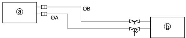
| Model | A | B |
| SEZ-KD25, 35 | 9.52 | 6.35 |
| SEZ-KD50 | 12.7 | 6.35 |
| SEZ-KD60 | 15.88 | 6.35 |
| SEZ-KD71 | 15.88 | 9.52 |
6.2
[Fig. 6-3]
Copper tubes
Good
No good
Tilted
Uneven
① Burred
[Fig. 6-4]
@ Burr
Copper tube/pipe


© Spare reamer
Pipe cutter
[Fig. 6-5]
③ Flare nut
⑤ Copper tube
[Fig. 6-6]
Flaring tool
Die
Copper tube
Flare nut
⑥ Yoke
[Fig. 6-7]
⑧ Smooth all around
⑤ Inside is shining without any scratches
Even length all around
Too much
⑥ Tilted
① Scratch on flared plane
Cracked
Unven
① Bad examples
6.3
[Fig. 6-8]
[Fig. 6-9]
Pipe cover (small) (accessory)
⑧ Caution:
Pull out the thermal insulation on the refrigerant piping at the site, insert the flare nut to flare the end, and replace the insulation in its original position.
Take care to ensure that condensation does not form on exposed copper piping.
Liquid end of refrigerant piping
Gas end of refrigerant piping
E Site refrigerant piping
E Main body
Pipe cover (large) (accessory)
Thermal insulation (field supply)
① Pull
③ Flare nut
Return to original position
Ensure that there is no gap here
Plate on main body
Band (accessory)
Ensure that there is no gap here. Place join upwards.
6.5
[Fig. 6-10]
Downward slope 1/100 or more
Connection dia. R1 external thread
Indoor unit
Collective piping
E Maximize this length to approx. 10 cm
[Fig. 6-11]
Indoor unit
Pipe cover (short) (accessory)
Tie band (accessory)
⑥ Band fixing part
⑥ Insertion margin
F Drain hose (accessory)
Drain pipe (O.D. 032 PVC TUBE, field supply)
Insulating material (field supply)
① Max. 145 ± 5 ~mm
7
[Fig. 7-1]
A Air inlet
⑧ Air outlet
© Access door
⑥ Ceiling surface
ECanvas duct
Air filter
Inlet grille
8
8.1
[Fig. 8-1]
8.2
[Fig. 8-2-1]
A Screw holding cover (2pcs)
Cover
[Fig. 8-2-3]
Use PG bushing to keep the weight of the cable and external force from being applied to the power supply terminal connector. Use a cable tie to secure the cable.
Power source wiring
Tensile force
Use ordinary bushing
① Signal receiving unit wiring
[Fig. 8-2-2]
Terminal bed box
⑧ Knockout hole
Remove
[Fig. 8-2-4]
① Terminal bed for power source and indoor transmission
To 1-phase power source
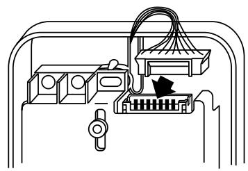
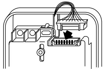
Connecting the signal receiving unit
Connect the signal receiving unit to the CN90 (Connect to the wireless remote controller board) on the indoor unit using the supplied remote controller wire. Connect the signal receiving units to all the indoor units.
[Fig. 8-3]
Indoor terminal block
Earth wire (green/yellow)
Indoor/outdoor unit connecting wire 3-core 1.5mm^2 or more
Outdoor terminal block
E Power supply cord: 2.0mm^2 or more
F Indoor controller board
① Connecting cable Cable 3-core 1.5mm^2 in conformity with Design 245 IEC 57.
② Indoor terminal block
③ Outdoor terminal block
4 Always install an earth wire (1-core 1.5 mm²) longer than other cables
⑤ Signal receiving unit cable (accessory)
(wire length: 5 m)
⑥ Signal receiving unit
⑦ Power supply cord Cable 3-core 2.0mm^2 or more, in con formity with Design 245 IEC 57.
8.3
[Fig. 8-4]
B
For installation in the switch box:
For direct installation on the wall select one of the following:
- Prepare a hole through the wall to pass the remote controller cord (in order to run the remote controller cord from the back), then seal the hole with putty.
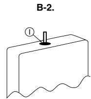
- Run the remote controller cord through the cut-out upper case, then seal the cut-out notch with putty similarly as above.
Wall
Conduit
Lock nut
F Bushing
Switch box
Remote controller cord
① Seal with putty
[Fig. 8-5]

Indoor/outdoor wiring Signal receiving unit wiring
Outdoor unit
Refrigerant address
Indoor unit
Signal receiving unit
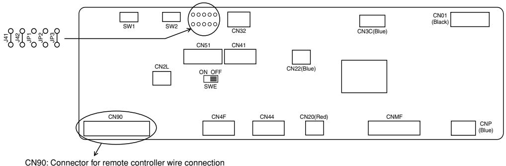
[Fig. 8-6]
Controller circuit board on the indoor unit (reference)
[Fig. 8-7]
[Fig. 8-8]
[Fig. 8-9]
[Fig. 8-10]
H
④ Signal receiving unit external
© Center of Switch box
Switch box
Installation pitch
⑥ 6.5 ~mm (1/4 inch)
F 70mm (2-3/4 inch)
⑥ 83.5± 0.4 mm (3-9/32 inch)
Protrusion (pillar, etc)
[Fig. 8-11]
Ceiling cassette type, Ceiling concealed type
Remote controller wire
⑧ Hole (drill a hole on the ceiling to pass the remote controller wire.)
Signal Receiving Unit
[Fig. 8-12]
Fix tightly with tape.
Remote controller wire
Order wire
[Fig. 8-13]
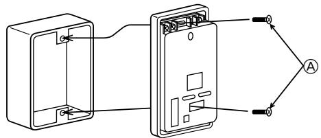
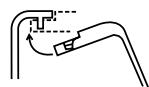
A
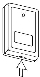
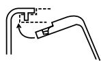
Insert the minus screwdriver toward the arrow pointed and wrench it to remove the cover.
A flat screwdriver whose width of blade is between 4 and 7mm (5/32 - 9/32 inch) must be used.
[Fig. 8-14]
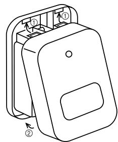
A
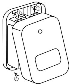
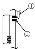
① Hang the cover to the upper hooks (2 places).
② Mount the cover to the lower case
Cross-section of upper hooks
[Fig. 8-15]
When using the switch box
When installing directly on the wall
A 150mm (5-15/16 inch)
Remote controller wire (Accessory)
Wiring pipe
Locknut
Bushing
Switch box
Seal around here with putty
Seal around here with putty
① Remote controller wire
① Seal around here with putty
[Fig. 8-16]
Insert the minus screwdriver toward the arrow pointed and wrench it to remove the cover.
A flat screwdriver whose width of blade is between 4 and 7mm (5/32 - 9/32 inch) must be used.
[Fig. 8-17]
A Thin-wall portion
Bottom case
Remote controller wire
Conducting wire
[Fig. 8-18]
A Screw (M4× 30)
- When installing the lower case directly on the wall or the ceiling, use wood screws.
[Fig. 8-19]
A
① Hang the cover to the upper hooks (2 places).
② Mount the cover to the lower case
Cross-section of upper hooks
8.4
[Fig.8-20]
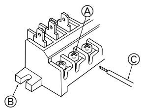
[Fig. 8-21]
A Loosen terminal screw
Terminal block
Lead wire
8.5
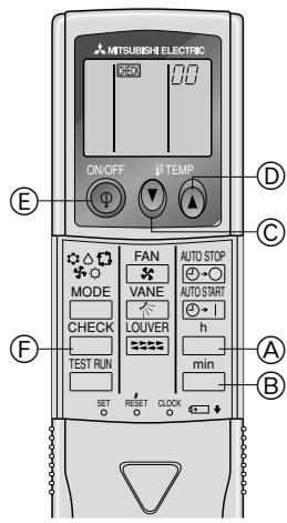
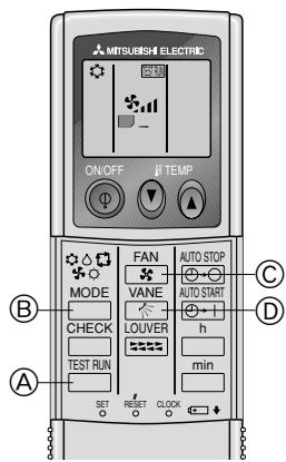
[Fig.8-22]
④ Hour button
⑧ Minute button
© TEMP button
TEMP button
⑥ ON/OFF button
CHECK button
9
9.1
[Fig. 9-1]
TEST RUN button
MODE button
© FAN button
VANE button
10
10.1
[Fig. 10-1]
Indoor unit
⑧ Union
Liquid pipe
Gas pipe
Stop valve
Outdoor unit
Refrigerant gas cylinder operating valve
Refrigerant gas cylinder for R410A with siphon
① Refrigerant (liquid)
③ Electronic scale for refrigerant charging
Charge hose (for R410A)
① Gauge manifold valve (for R410A)
M Service port
- Safety precautions 9
- Selecting the installation location 9
- Selecting an installation site & Accessories 10
- Fixing hanging bolts 10
- Installing the unit 10
- Refrigerant piping work 11
- Duct work 12
- Electrical work 13
9.Test run 15
10. Maintenance 17
This Installation Manual describes only for the indoor unit and the connected outdoor unit of SUZ series.
If the connected outdoor unit is MXZ series, refer to the Installation Manual for MXZ series.
1. Safety precautions
- Please report to or take consent by the supply authority before connection to the system.
- Be sure to read "The following should always be observed for safety" before installing the air conditioner.
- Be sure to observe the cautions specified here as they include important items related to safety.
- The indications and meanings are as follows.
Warning:
Could lead to death, serious injury, etc.
Caution:
Could lead to serious injury in particular environments when operated incorrectly.
- After reading this manual, be sure to keep it together with the instruction manual in a handy place on the customer's site.
Warning:
- Do not install it by yourself (customer).
Incomplete installation could cause injury due to fire, electric shock, the unit falling or leakage of water. Consult the dealer from whom you purchased the unit or special installer. - Install the unit securely in a place which can bear the weight of the unit.
When installed in an insufficient strong place, the unit could fall causing injured.
- Use the specified wires to connect the indoor and outdoor units securely and attach the wires firmly to the terminal board connecting sections so the stress of the wires is not applied to the sections. Incomplete connecting and fixing could cause fire.
- Do not use intermediate connection of the power cord or the extension cord and do not connect many devices to one AC outlet.
It could cause a fire or an electric shock due to defective contact, defective insulation, exceeding the permissible current, etc.
- Check that the refrigerant gas does not leak after installation has completed.
Caution:
- Perform grounding.
Do not connect the ground wire to a gas pipe, water pipe arrester or telephone ground wire. Defective grounding could cause an electric shock. - Do not install the unit in a place where an inflammable gas leaks.
If gas leaks and accumulates in the area surrounding the unit, it could cause an explosion. - Install a ground leakage breaker depending on the installation place (where it is humid).
If a ground leakage breaker is not installed, it could cause an electric shock.
2. Selecting the installation location
2.1. Indoor unit
- Where airflow is not blocked.
- Where cool air spreads over the entire room.
- Where it is not exposed to direct sunshine.
- At a distance 1 m or more away from your TV and radio (to prevent picture from being distorted or noise from being generated).
- In a place as far away as possible from fluorescent and incandescent lights (so the infrared remote control can operate the air conditioner normally).
2.2. Outdoor unit
- Where it is not exposed to strong wind.
- Where airflow is good and dustless.
- Where it is not exposed to rain and direct sunshine.
- Where neighbours are not annoyed by operation sound or hot air.
- Where rigid wall or support is available to prevent the increase of operation sound or vibration.
- Where there is no risk of combustible gas leakage.
- When installing the unit at a high level, be sure to fix the unit legs.
- Where it is at least 3m away from the antenna of TV set or radio. (Otherwise, images would be disturbed or noise would be generated.)
Symbols put on the unit
: Indicates an action that must be avoided.
: Indicates that important instructions must be followed.
: Indicates a part which must be grounded.
: Indicates that caution should be taken with rotating parts.
: Indicates that the main switch must be turned off before servicing.
A: Beware of electric shock.
Beware of hot surface.
Warning:
Carefully read the labels affixed to the main unit.
- Perform the installation securely referring to the installation manual.
Incomplete installation could cause a personal injury due to fire, electric shock, the unit falling or leakage of water. - Perform electrical work according to the installation manual and be sure to use an exclusive circuit.
If the capacity of the power circuit is insufficient or there is incomplete electrical work, it could result in a fire or an electric shock. - Attach the electrical part cover to the indoor unit and the service panel to the outdoor unit securely.
If the electrical part cover in the indoor unit and/or the service panel in the outdoor unit are not attached securely, it could result in a fire or an electric shock due to dust, water, etc. - Be sure to use the part provided or specified parts for the installation work. The use of defective parts could cause an injury or leakage of water due to a fire, an electric shock, the unit falling, etc.
- Ventilate the room if refrigerant leaks during operation.
If the refrigerant comes in contact with a flame, poisonous gases will be released.
- Perform the drainage/ piping work securely according to the installation manual.
If there is a defect in the drainage/piping work, water could drop from the unit and household goods could be wet and damaged. -
Fasten a flare nut with a torque wrench as specified in this manual.
When fastened too tight, a flare nut may broken after a long period and cause a leakage of refrigerant. -
Where the air filter can be removed and replaced easily.
Warning:
Mount the indoor unit into a ceiling strong enough to withstand the weight of the unit.
- Install the unit horizontally.
Caution:
Avoid the following places for installation where air conditioner trouble is liable to occur. - Where there is too much machine oil.
- Salty environment as seaside areas.
- Hot-spring areas.
- Where sulfide gas exists.
-
Other special atmospheric areas.
-
Select a site with sturdy fixed surface sufficiently durable against the weight of unit.
- Before installing unit, the routing to carry in unit to the installation site should be determined.
- Select a site where the unit is not affected by entering air.
- Select a site where the flow of supply and return air is not blocked.
- Select a site where refrigerant piping can easily be led to the outside.
- Select a site which allows the supply air to be distributed fully in room.
- Do not install unit at a site with oil splashing or steam in much quantity.
- Do not install unit at a site where combustible gas may generate, flow in, stagnate or leak.
- Do not install unit at a site where equipment generating high frequency waves (a high frequency wave welder for example) is provided.
- Do not install unit at a site where fire detector is located at the supply air side. (Fire detector may operate erroneously due to the heated air supplied during heating operation.)
- When special chemical product may scatter around such as site chemical plants and hospitals, full investigation is required before installing unit. (The plastic components may be damaged depending on the chemical product applied.)
- If the unit is run for long hours when the air above the ceiling is at high temperature/ high humidity (due point above 26^ ), due condensation may be produced in the indoor unit. When operating the units in this condition, add insulation material (10-20 mm) to the entire surface of the indoor unit to avoid due condensation.
3.1. Install the indoor unit on a ceiling strong enough to sustain its weight
[Fig. 3-1] (P.2)
A Access door
⑧ Electrical parts box
Air inlet
⑥ Air outlet
Ceiling surface
Service space (viewed from the side)
Service space (viewed from the direction of arrow)
① 600 mm or more
② 100 mm or more
③ 10 mm or more
(4) 300 ~mm or more
- If the optional long-life filter is installed, the dimensions of the air conditioner increase.
Rear inlet: Depth increases by 30~mm( 1)
Bottom inlet: Height increases by 30mm (^*2)
Warning:
The unit must be securely installed on a structure that can sustain its weight. If the unit is mounted on an unstable structure, it may fall down causing injuries.
3.2. Securing installation and service space
- Select the optimum direction of supply airflow according to the configuration of the room and the installation position.
- As the piping and wiring are connected at the bottom and side surfaces, and the maintenance is made at the same surfaces, allow a proper space properly. For the efficient suspension work and safety, provide a space as much as possible.
3.3. Outdoor unit
Ventilation and service space
SUZ-KA25VA
[Fig. 3-2] (P.2)
A 100mm or more
⑧ 350 mm or more
⑤ Basically open 100~mm or more without only obstruction in front and on both sides of the unit.
① 200 mm or more (Open two sides of left, right, or rear side.)
When the piping is to be attached to a wall containing metals (tin plated) or metal netting, use a chemically treated wooden piece 20mm or thicker between the wall and the piping or wrap 7 to 8 turns of insulation vinyl tape around the piping.
Units should be installed by licensed contractor accordingly to local code requirement.
3.4. Indoor unit accessories
The unit is provided with the following accessories:
| No. | Name | Quantity |
| ① | Pipe cover (for refrigerant piping joint) Small diameter | 1 |
| ② | Pipe cover (for refrigerant piping joint) Large diameter | 1 |
| ③ | Bands for temporary tightening of pipe cover and drain hose | 6 |
| ④ | Remote controller parts | 1 |
| ⑤ | Signal receiving unit | 1 |
| ⑥ | Signal receiving unit cable | 1 |
| ⑦ | Washer | 8 |
| ⑧ | Drain hose | 1 |
| ⑨ | Pipe cover (for Drain hose) short | 1 |
4. Fixing hanging bolts
4.1. Fixing hanging bolts
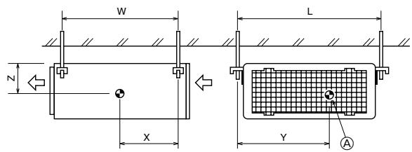
[Fig. 4-1] (P.2)
Center of gravity
(Give site of suspension strong structure.)
Hanging structure
- Ceiling: The ceiling structure varies from building to one another. For detailed information, consult your construction company.
Center of gravity and Product Weight
| Model name | W | L | X | Y | Z | Product Weight (kg) |
| SEZ-KD25 | 625 | 752 | 263 | 351 | 106 | 18 |
| SEZ-KD35 | 625 | 952 | 286 | 448 | 104 | 21 |
| SEZ-KD50 | 625 | 952 | 280 | 437 | 104 | 24 |
| SEZ-KD60 | 625 | 1152 | 285 | 527 | 104 | 28 |
| SEZ-KD71 | 625 | 1152 | 285 | 527 | 104 | 28 |
5. Installing the unit
5.1. Hanging the unit body
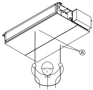
Bring the indoor unit to an installation site as it is packed.
To hang the indoor unit, use a lifting machine to lift and pass through the hanging bolts.
[Fig. 5-1] (P.2)
④ Unit body
⑧ Lifting machine
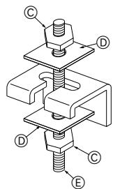
[Fig. 5-2] (P.2)
Nuts (field supply)
⑥ Washers (accessory)
E M10 hanging bolt (field supply)
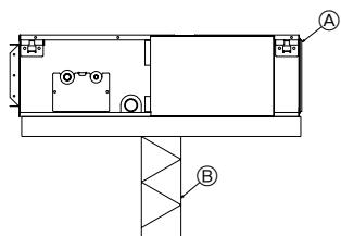
5.2. Confirming the unit's position and fixing hanging bolts
- Use the gage supplied with the panel to confirm that the unit body and hanging bolts are positioned in place. If they are not positioned in place, it may result in dew drops due to wind leak. Be sure to check the positional relationship.
Use a level to check that the surface indicated by is at level. Ensure that the hanging bolt nuts are tightened to fix the hanging bolts.
To ensure that drain is discharged, be sure to hang the unit at level using a level.
[Fig. 5-3] (P.2)
Indoor unit's bottom surface
Caution:
Be sure to install the unit body at level.
6.1. Refrigerant pipe
[Fig. 6-1] (P.3)
Indoor unit
⑥ Outdoor unit
Refer to the Instruction Manual that came with the outdoor unit for the restrictions on the height difference between units and for the amount of additional refrigerant charge.
Avoid the following places for installation where air conditioner trouble is liable to occur.
- Where there is too much oil such as for machine or cooking.
- Salty environment as seaside areas.
Hot-spring areas.
- Where sulfide gas exists.
- Other special atmospheric areas.
- This unit has flared connections on both indoor and outdoor sides. (Fig. 6-1)
- Refrigerant pipes are used to connect the indoor and outdoor units as shown in the figure below.
- Insulate both refrigerant and drainage piping completely to prevent condensation.
Piping preparation
- Refrigerant pipes of 3, 5, 7, 10 and 15 m are available as optional items.
(1) Table below shows the specifications of pipes commercially available.
| Model | Pipe | Outside diameter | Min wall thickness | Insulation thickness | Insulation material | |
| mm | inch | |||||
| SEZ-KD25 | For liquid | 6.35 | 1/4 | 0.8 mm | 8 mm | Heat resisting foam plastic 0.045 specific gravity |
| For gas | 9.52 | 3/8 | 0.8 mm | 8 mm | ||
| SEZ-KD35 | For liquid | 6.35 | 1/4 | 0.8 mm | 8 mm | |
| For gas | 9.52 | 3/8 | 0.8 mm | 8 mm | ||
| SEZ-KD50 | For liquid | 6.35 | 1/4 | 0.8 mm | 8 mm | |
| For gas | 12.7 | 1/2 | 0.8 mm | 8 mm | ||
| SEZ-KD60 | For liquid | 6.35 | 1/4 | 0.8 mm | 8 mm | |
| For gas | 15.88 | 5/8 | 1.0 mm | 8 mm | ||
| SEZ-KD71 | For liquid | 9.52 | 3/8 | 0.8 mm | 8 mm | |
| For gas | 15.88 | 5/8 | 1.0 mm | 8 mm | ||
(2) Ensure that the 2 refrigerant pipes are well insulated to prevent condensation.
(3) Refrigerant pipe bending radius must be 10cm or more.

Caution:
Using careful insulation of specified thickness. Excessive thickness prevents storage behind the indoor unit and smaller thickness causes dew drippage.
6.2. Flaring work
- Main cause of gas leakage is defect in flaring work.
Carry out correct flaring work in the following procedure.
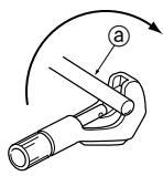
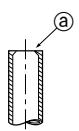
6.2.1. Pipe cutting
[Fig. 6-3] (P.3)
Copper tubes
Good
© No good
Tilted
Uneven
① Burred
- Using a pipe cutter cut the copper tube correctly.
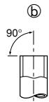
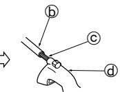
6.2.2. Burrs removal
[Fig. 6-4] (P.3)
a Burr
Copper tube/pipe
© Spare reamer
Pipe cutter
- Completely remove all burrs from the cut cross section of pipe/tube.
- Put the end of the copper tube/pipe to downward direction as you remove burrs in order to avoid burrs drop in the tubing.
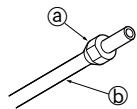
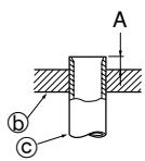
6.2.3. Putting nut on
[Fig. 6-5] (P.3)
Flare nut
Copper tube
- Remove flare nuts attached to indoor and outdoor unit, then put them on pipe/tube having completed burr removal.
(not possible to put them on after flaring work)
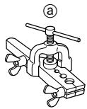
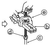
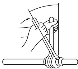
6.2.4. Flaring work
[Fig. 6-6] (P.3)
Flaring tool
Die
Copper tube
Flare nut
⑥ Yoke
- Carry out flaring work using flaring tool as shown below.
| Pipe diameter (mm) | Dimension | |
| A (mm) | B *0.4 (mm) | |
| When the tool for R410A is used | ||
| Clutch type | ||
| 6.35 | 0 - 0.5 | 9.1 |
| 9.52 | 0 - 0.5 | 13.2 |
| 12.7 | 0 - 0.5 | 16.6 |
| 15.88 | 0 - 0.5 | 19.7 |
Firmly hold copper tube in a die in the dimension shown in the table at above.
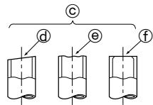
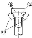
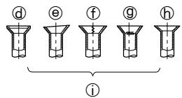
6.2.5. Check
[Fig. 6-7] (P.3)
⑧ Smooth all around
⑥ Inside is shining without any scratches
Even length all around
Too much
⑥ Tilted
① Scratch on flared plane
⑨ Cracked
Uneven
① Bad examples
- Compare the flared work with a figure in right side hand.
- If flare is noted to be defective, cut off the flared section and do flaring work again.
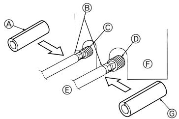
6.3. Pipe connection
[Fig. 6-8] (P.3)
- Apply a thin coat of refrigeration oil on the seat surface of pipe.
- For connection first align the center, then tighten the first 3 to 4 turns of flare nut.
- Use tightening torque table below as a guideline for indoor unit side union joint section, and tighten using two wrenches. Excessive tightening damages the flare section.
| Copper pipe O.D. (mm) | Flare nut O.D. (mm) | Tightening torque (N·m) |
| ø6.35 | 17 | 14 - 18 |
| ø9.52 | 22 | 34 - 42 |
| ø12.7 | 26 | 49 - 61 |
| ø15.88 | 29 | 68 - 82 |
![MITSUBISHI SEZ-KD50VAL - [Fig. 6-8] (P.3) - 1](/content/2019/07/158900/images/092dee285e427c33da32bd7ce29baa5ae39b60721ad333ae2fd0c61304128af9.jpg)
Warning:
Be careful of flying flare nut! (Internally pressurized)
Remove the flare nut as follows:
- Loosen the nut until you hear a hissing noise.
- Do not remove the nut until the gas has been completely released (i.e., hissing noise stops).
- Check that the gas has been completely released, and then remove the nut.
Outdoor unit connection
Connect pipes to stop valve pipe joint of the outdoor unit in the same manner applied for indoor unit.
- For tightening use a torque wrench or spanner, and use the same tightening torque applied for indoor unit.
Refrigerant pipe insulation
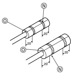
- After connecting refrigerant piping, insulate the joints (flared joints) with thermal insulation tubing as shown below.
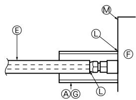
[Fig. 6-9] (P.3)
Pipe cover (small) (accessory)
Caution:
Pull out the thermal insulation on the refrigerant piping at the site, insert the flare nut to flare the end, and replace the insulation in its original position.
Take care to ensure that condensation does not form on exposed copper piping.
Liquid end of refrigerant piping
Site refrigerant piping
Pipe cover (large) (accessory)
① Pull
Return to original position
Plate on main body
Ensure that there is no gap here. Place join upwards.
upwards.
Gas end of refrigerant piping
Main body
Thermal insulation (field supply)
① Flare nut
Ensure that there is no gap here
Band (accessory)
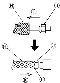
- Remove and discard the rubber bung which is inserted in the end of the unit piping.
2.Flare the end of the site refrigerant piping.
3.Pull out the thermal insulation on the site refrigerant piping and replace the insulation in its original position.
Cautions On Refrigerant Piping
Be sure to use non-oxidative brazing for brazing to ensure that no foreign matter or moisture enter into the pipe.
Be sure to apply refrigerating machine oil over the flare connection seating surface and tighten the connection using a double spanner.
- Provide a metal brace to support the refrigerant pipe so that no load is imparted to the indoor unit end pipe. This metal brace should be provided 50~cm away from the indoor unit's flare connection.
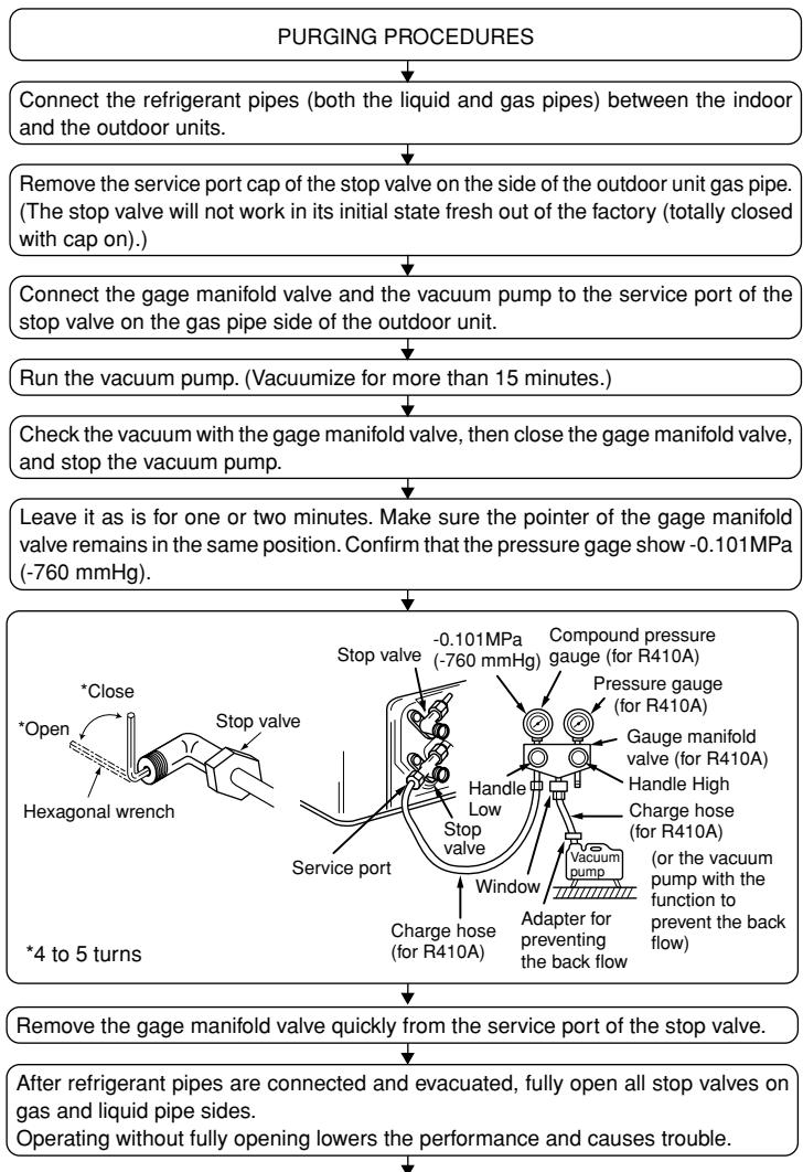
6.4. Purging procedures leak test
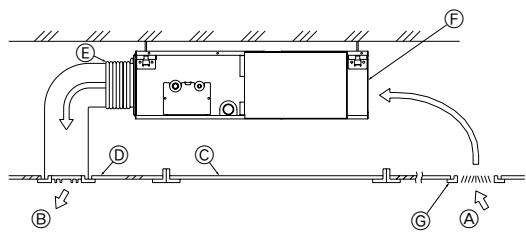
7. Duct work
- When connecting ducts, insert a canvas duct between the main body and the duct.
- Use non-combustible duct components.
Caution:
- The noise from the intake will increase dramatically if intake is fitted directly beneath the main body. Intake should therefore be installed as far away from the main body as possible.
Particular care is required when using it with bottom inlet specifications. - Install sufficient thermal insulation to prevent condensation forming on outlet duct flanges and outlet ducts.
- To connect the air conditioner main body and the duct for potential equalization.
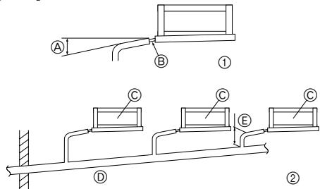
6.5. Drain piping work
- Ensure that the drain piping is downward (pitch of more than 1/100) to the outdoor (discharge) side. Do not provide any trap or irregularity on the way. (①)
- Ensure that any cross-wise drain piping is less than 20m (excluding the difference of elevation). If the drain piping is long, provide metal braces to prevent it from waving. Never provide any air vent pipe. Otherwise drain may be ejected.
- Use a hard vinyl chloride pipe O.D. 032 for drain piping.
- Ensure that collected pipes are 10cm lower than the unit body's drain port as shown in ②.
- Do not provide any odor trap at the drain discharge port.
- Put the end of the drain piping in a position where no odor is generated.
- Do not put the end of the drain piping in any drain where ionic gases are generated.
[Fig. 6-10] (P.3)
Downward slope 1/100 or more
Connection dia. R1 external thread
Indoor unit
⑥ Collective piping
E Maximize this length to approx. 10cm
1.Insert the drain hose (accessory) into the drain port.
(The drain hose must not be bent more than 45^ to prevent the hose from breaking or clogging.)
The connecting part between the indoor unit and the drain hose may be disconnected at the maintenance. Fix the part with the accessory band, not be adhered.
2. Attach the drain pipe (O.D. 032 PVC TUBE, field supply).
(Attach the pipe with glue for the hard vinyl chloride pipe, and fix it with the band (small, accessory).)
3. Perform insulation work on the drain pipe (O.D.ø32 PVC TUBE) and on the socket (including elbow).
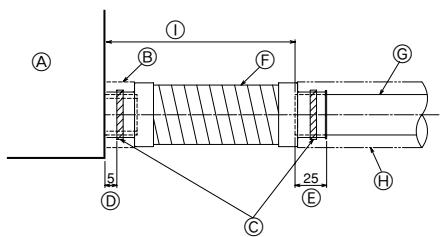
[Fig. 6-11] (P.3)
Indoor unit
Pipe cover (short) (accessory)
Tie band (accessory)
⑥ Band fixing part
⑥ Insertion margin
F Drain hose (accessory)
Drain pipe (O.D. 032 PVC TUBE, field supply)
Insulating material (field supply)
① Max. 145 ± 5 ~mm
- Keep the distance between the inlet grille and the fan over 850~mm . If it is less than 850~mm , install a safety guard not to touch the fan.
[Fig. 7-1] (P.4)
A Air inlet
Air outlet
© Access door
⑥ Ceiling surface
ECanvas duct
Air filter
Inlet grille
8.1. Power supply
| Electrical specification | Input capacity Main Switch/Fuse (A) | ||||
| Power supply (1 phase ~/N, 230V, 50Hz) | SEZ-KD25 | SEZ-KD35 | SEZ-KD50 | SEZ-KD60 | SEZ-KD71 |
| 10 | 10 | 20 | 20 | 20 | |
Warning:
- The compressor will not operate unless the power supply phase connection is correct.
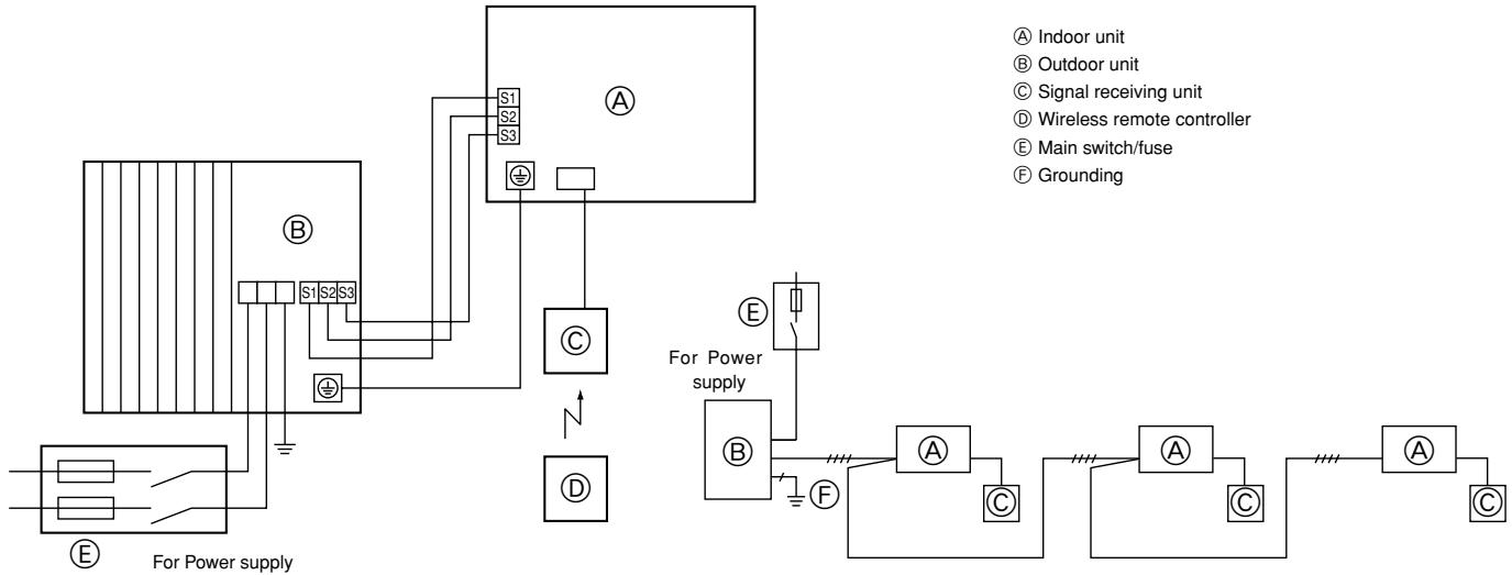
- Grounding protection with a no-fuse breaker (earth leakage breaker [ELB]) is usually installed for ① .
- The connection wiring between the outdoor and indoor units can be extended up to a maximum of 50 meters, and the total extension including the crossover wiring between rooms is a maximum of 80m .
A switch with at least 3mm contact separation in each pole shall be provided by the air conditioner installation.
- Label each breaker according to purpose (heater, unit etc.).
[Fig. 8-1] (P.4)
Indoor unit
Outdoor unit
Signal receiving unit
Wireless remote controller
E Main switch/fuse
Grounding
8.2. Indoor wire connection
Work procedure
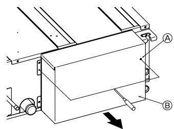
- Remove 2 screws to detach the electric component cover.
- Route each cable through the wiring intake into the electric component box. (Procure power cable and in-out connecting cable locally and use remote control cable supplied with the unit.)
- Securely connect the power cable and the in-out connecting cable and the remote control cable to the terminal blocks.
- Secure the cables with clamps inside the electric component box.
- Attach the electric component cover as it was.
- Fix power supply cable and indoor/outdoor cable to control box by using buffer bushing for tensile force. (PG connection or the like.)
Warning:
- Attach the electrical part cover securely. If it is attached incorrectly, it could result in a fire, electric shock due to dust, water, etc.
- Use the specified indoor/outdoor unit connecting wire to connect the indoor and outdoor units and fix the wire to the terminal bed securely so that no stress is applied to the connecting section of the terminal bed. Incomplete connection or fixing of the wire could result in a fire.
[Fig. 8-2-1] (P.4)
Screw holding cover (2 pcs)
⑧ Cover
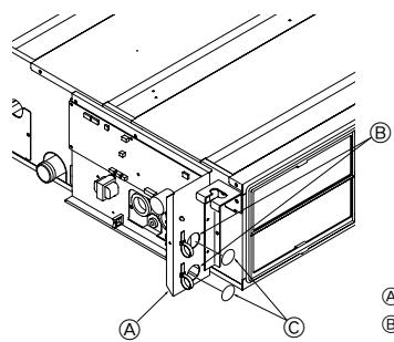
[Fig. 8-2-2] (P.4)
Terminal bed box
⑧ Knockout hole
Remove
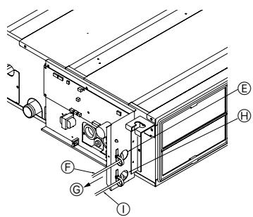
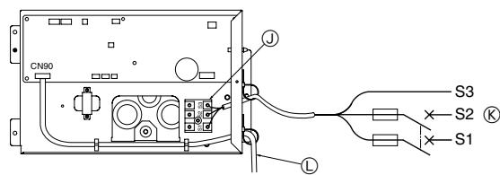
[Fig. 8-2-3] (P.4)
Use PG bushing to keep the weight of the cable and external force from being applied to the power supply terminal connector. Use a cable tie to secure the cable.
Power source wiring
Tensile force
Use ordinary bushing
① Signal receiving unit wiring
[Fig. 8-2-4] (P.4)
① Terminal bed for power source and indoor transmission
To 1-phase power source
Connecting the signal receiving unit
Connect the signal receiving unit to the CN90 (Connect to the wireless remote controller board) on the indoor unit using the supplied remote controller wire. Connect the signal receiving units to all the indoor units.
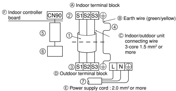
- Perform wiring as shown in the diagram to the lower left. (Procure the cable locally.) Make sure to use cables of the correct polarity only.
[Fig. 8-3] (P.5)
Indoor terminal block
⑧ Earth wire (green/yellow)
Indoor/outdoor unit connecting wire 3-core 1.5 ~mm^2 or more
Outdoor terminal block
E Power supply cord: 2.0mm^2 or more
Indoor controller board
① Connecting cable
Cable 3-core 1.5mm^2 in conformity with Design 245 IEC 57.
② Indoor terminal block
③ Outdoor terminal block
④ Always install an earth wire (1-core 1.5mm^2 ) longer than other cables
⑤ Signal receiving unit cable (accessory) (wire length: 5 m)
⑥ Signal receiving unit
⑦ Power supply cord
Cable 3-core 2.0mm^2 or more, in conformity with Design 245 IEC 57.
- Connect the terminal blocks as shown in the diagram below.
Caution:
- Use care not to make mis-wiring.
- Firmly tighten the terminal screws to prevent them from loosening.
- After tightening, pull the wires lightly to confirm that they do not move.
8.3. Remote controller
8.3.1. For wireless remote controller
1) Installing procedures
(1) Select an installing position for the remote controller.
The temperature sensors are located on both remote controller and indoor unit.
Procure the following parts locally:
Two piece switch box
Thin copper conduit tube
Lock nuts and bushings
(2) Seal the service entrance for the remote controller cord with putty to prevent possible invasion of dew drops, water, cockroaches or worms.
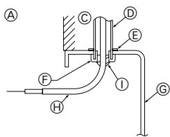
[Fig. 8-4] (P.5)
For installation in the switch box:
For direct installation on the wall select one of the following:
- Prepare a hole through the wall to pass the remote controller cord (in order to run the remote controller cord from the back), then seal the hole with putty.
- Run the remote controller cord through the cut-out upper case, then seal the cut-out notch with putty similarly as above.
Wall
Conduit
E Lock nut
Bushing
⑥ Switch box
Remote controller cord
① Seal with putty
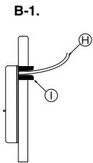
B-1. To lead the remote controller cord from the back of the controller:
B-2. To run the remote controller cord through the upper portion:
(3) For direct installation on the wall
8.3.2. Signal Receiving Unit
1) Sample system connection
[Fig. 8-5] (P.5)
Only the wiring from the signal receiving unit and between the remote controllers is shown in Fig. 8-5. The wiring differs depending on the unit to be connected or the system to be used.
For details on restrictions, refer to the installation manual or the service handbook that came with the unit.
1. Connecting to Mr. SLIM air conditioner
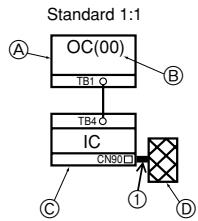
(1) Standard 1:1
① Connecting the signal receiving unit
Connect the signal receiving unit to the CN90 (Connect to the wireless remote controller board) on the indoor unit using the supplied remote controller wire. Connect the signal receiving units to all the indoor units.
2) Setting the pair number switch
[Fig. 8-6] (P.5)
1. Setting method
Assign the same pair number to the wireless remote controller as that of the indoor unit. If not doing so, the remote controller cannot be operated. Refer to the installation manual that came with the wireless remote controller for how to set pair numbers of wireless remote controllers.
Position of daisy wire on the controller circuit board on the indoor unit.
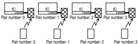
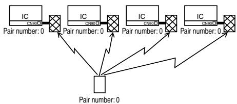
For pair number settings, the following 4 patterns (A-D) are available.
| Pair number setting pattern | Pair number on remote controller side | Indoor controller circuit board side Point where the daisy wire is disconnected |
| A | 0 | Not disconnected |
| B | 1 | J41 disconnected |
| C | 2 | J42 disconnected |
| D | 3~9 | J41 and J42 disconnected |
2. Setting example
(1) To use the units in the same room
[Fig. 8-7] (P.5)
① Separate setting
Assign a different pair number to each indoor unit to operate each indoor unit by its own wireless remote controller.
[Fig. 8-8] (P.5)
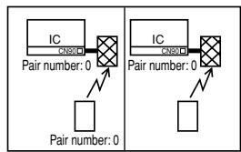
② Single setting
Assign the same pair number to all the indoor units to operate all the indoor units by a single wireless remote controller.
[Fig. 8-9] (P.5)
(2) To use the units in different rooms
Assign the same pair number to the wireless remote controller as that of the indoor unit. (Leave the setting as it is at purchase.)
3) How To Install
[Fig. 8-10] (P.6) to [Fig. 8-19] (P.7)
- Common items for "Installation on the ceiling" and "Installation on the switch box or on the wall"
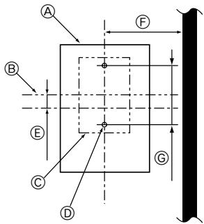
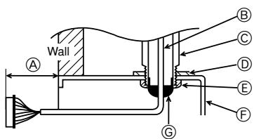
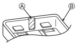
[Fig. 8-10] (P.6)
Signal receiving unit external
E 6.5mm (1/4 inch)
Center of Switch box
F 70mm (2-3/4 inch)
Switch box
⑥ 83.5± 0.4mm (3-9/32 inch)
⑥ Installation pitch
Protrusion (pillar, etc)
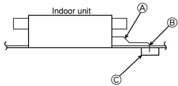
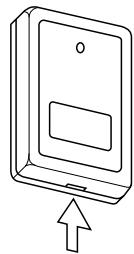
[Fig. 8-11]
Remote controller wire
⑧ Hole (drill a hole on the ceiling to pass the remote controller wire.)
Signal Receiving Unit
(1) Select the installation site.
The following must be observed.
① Connect the signal receiving unit to the indoor unit with the supplied remote controller wire. Note that the length of the remote controller wire is 5m (16 ft). Install the remote controller within the reach of the remote controller wire.
② When installing on either the switch box or the wall, allow space around the Signal Receiving Unit as shown in the figure in [Fig. 8-10].
③ When installing the Signal Receiving Unit to the switch box, the Signal Receiving Unit slipped downward for 6.5mm (1/4 inch) as right illustrated.
④ Parts which must be supplied on site. Switch box for one unit Thin-copper wiring pipe Lock nut and bushing
⑤ The thickness of the ceiling to which the remote controller is installed must be between 9 mm (3/8 inch) and 25 mm (1 inch).
⑥ Install the unit on the ceiling or on the wall where the signal can be received from the wireless remote controller. The area where the signal from the wireless remote controller can be received is 45^ and 7m (22 ft) away from the front of the signal receiving unit.
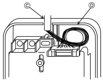
⑦ Install the signal receiving unit to the position depending on the indoor unit model.
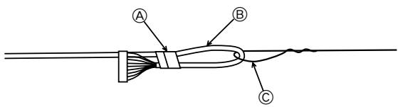
⑧ Connect the remote controller wire securely to the order wire. To pass the remote controller wire through the conduit, follow the procedure as shown in Fig. 8-12.
[Fig. 8-12] (P.6)
Fix tightly with tape.
Order wire
Remote controller wire
Note:
- The point where the remote controller wire is connected differs depending on the indoor unit model.
Take into account that the remote controller wire cannot be extended when selecting the installation site.
- If the Signal Receiving Unit is installed near a fluorescent lamp specially inverter type, signal interception may occur.
Be careful for installing the Signal Receiving Unit or replacing the lamp.
- Installation on the switch box or on the wall
(1) Use the remote controller wire to connect it to the connector (CN90) on the controller circuit board on the indoor unit.
Refer to the 2) Setting the Pair Number Switch for details on controller circuit board on the indoor unit.
(2) Seal the Signal Receiving Unit cord lead-in hole with putty in order to prevent the possible entry of dew, water droplets, cockroaches, other insects, etc.
[Fig. 8-15] (P.6)
A 150mm (5-15/16 inch)
Remote controller wire (Accessory)
Wiring pipe
Locknut
E Bushing
F Switch box
⑥ Seal around here with putty
- When installing on the switch box, seal the connections between the switch box and wiring pipe with putty.
[Fig. 8-15] (P.6)
Seal around here with putty
① Remote controller wire
① Seal around here with putty
- When opening a hole using a drill for Signal Receiving Unit wire (or taking the wire out of the back of the Signal Receiving Unit), seal that hole with putty.
- When routing the wire via the portion cut off from the upper case, equally seal that portion with putty.
(3) Install the remote control wire to the terminal block. (Fig. 8-16)
(4) Installing hole when the Signal Receiving Unit is installed on the wall direct. (Fig. 8-17)
- Cut the thin-wall portion inside the bottom case (oblique section) by a knife or a nipper.
- Take out the connected remote controller wire to the terminal brock through this space.
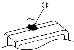
(5) Install the lower case on the switch box or directly on the wall. (Fig. 8-18) Mounting the cover (Fig. 8-19)
Caution:
- Insert the cover securely until the clicking sound is made. If not doing so, the cover may fall.
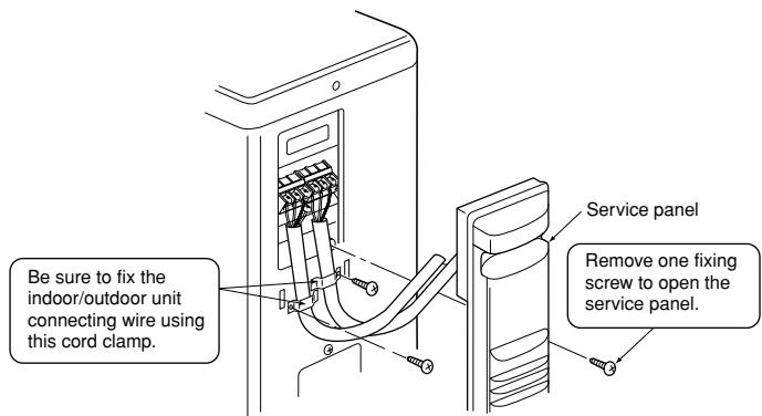
8.4. Outdoor unit
[Fig. 8-20] (P.7)
- Connect cable from the indoor unit correctly on the terminal-block.
- Use the same terminal block and polarity as is used with the indoor unit.
-
For aftercare maintenance, give extra length to connecting cable.
-
Both end of connecting cable (extension wire) are peeled off. When too long, or connected by cutting off the middle, peel off power supply cable to the size given in the figure.
- Be careful not to contact connecting cable with piping.
[Fig. 8-21] (P.7)
A Loosen terminal screw
B Terminal block
Lead wire
Caution:
- Use care not to make mis-wiring. (Fig. 8-21)
- Firmly tighten the terminal screws to prevent them from loosening.
- After tightening, pull the wires lightly to confirm that they do not move.
Warning:
- Be sure to attach the service panel of the outdoor unit securely. If it is not attached correctly, it could result in a fire or an electric shock due to dust, water, etc.
- Tighten terminal screws securely.
- Wiring should be done so that the power lines are not subject to tension. Otherwise, heat may be generated or fire may occur.
8.5. Function settings
8.5.1 Function setting on the unit (Selecting the unit functions)
1) AUTO RESTART FUNCTION
For wireless remote controller only [Fig. 8-22] (P.8)
This model is equipped with the AUTO RESTART FUNCTION.
When the indoor unit is controlled with the remote controller, the operation mode, set temperature, and the fan speed are memorized by the indoor controller board. The auto restart function sets to work the moment the power has restored after power failure, then, the unit will restart automatically.
8.5.2. Function setting on the unit (Selecting the unit functions) [Fig. 8-22] (P.8)
Changing the power voltage setting
- Be sure to change the power voltage setting depending on the voltage used.
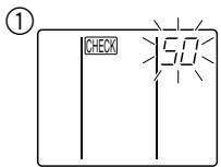
① Go to the function select mode
Press the CHECK button twice continuously. (Start this operation from the status of remote controller display turned off.) check is lighted and "00" blinks.
Press the TEMP button once to set "50". Direct the wireless remote controller toward the receiver of the indoor unit and press the Hour button
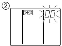
② Setting the unit number
Press the TEMP button and to set the unit number "00". Direct the wireless remote controller toward the receiver of the indoor unit and press the Minute button 包
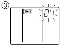
③ Selecting a mode
Enter 04 to change the power voltage setting using the and buttons. Direct the wireless remote controller toward the receiver of the indoor unit and press the Hour button A.
Current setting number:
1 = 1 beep(one second)
2 = 2 beeps (one second each)
3 = 3 beeps (one second each)
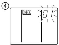
④ Selecting the setting number
Use the and buttons to change the power voltage setting to 01 (240 V). Direct the wireless remote controller toward the sensor of the indoor unit and press the Hour button
⑤ To select multiple functions continuously
Repeat steps ③ and ④ to change multiple function settings continuously.
⑥ Complete function selection
toward the sensor of the indoor unit and
Note:
- Whenever changes are made to the function settings after installation or maintenance, be sure to record the changes with a mark in the "Setting" column of the Function table.
8.5.3 Function setting on the remote controller
Refer to the indoor unit operation manual.
Function table
Select unit number 00
| Mode | Settings | Mode no. | Setting no. | Initial setting | Setting |
| Power failure automatic recovery*1(AUTO RESTART FUNCTION) | Not available | 01 | 1 | ○ (*1) | |
| Available | 2 | ||||
| Indoor temperature detecting | Indoor unit operating average | 02 | 1 | ○ | |
| Set by indoor unit's remote controller | 2 | ||||
| Remote controller's internal sensor | 3 | ||||
| LOSSNAY connectivity | Not Supported | 03 | 1 | ○ | |
| Supported (indoor unit is not equipped with outdoor-air intake) | 2 | ||||
| Supported (indoor unit is equipped with outdoor-air intake) | 3 | ||||
| Auto mode | Energy saving cycle automatically enabled | 05 | 1 | ○ | |
| Energy saving cycle automatically disabled | 2 |
Select unit numbers 01 to 03 or all units (AL [wired remote controller]/07 [wireless remote controller])
| Mode | Settings | Mode no. | Setting no. | Initial setting | Setting |
| Filter sign | 100 Hr | 07 | 1 | ||
| 2500 Hr | 2 | ||||
| No filter sign indicator | 3 | ○ | |||
| External static pressure | 15 Pa | 08 | 1 | ○ | |
| 35 Pa | 2 | ||||
| 50 Pa | 3 | ||||
| The same as setting of mode no.08 | 10 | 1 | ○ | ||
| 5 Pa (set mode no. 08 to 1) | 2 |
*1 When the power supply returns, the air conditioner will start 3 minutes later.
9. Test run
9.1. Before test run
After completing installation and the wiring and piping of the indoor and outdoor units, check for refrigerant leakage, looseness in the power supply or control wiring, wrong polarity, and no disconnection of one phase in the supply.
- Use a 500-volt megohmmeter to check that the resistance between the power supply terminals and ground is at least 1.0M
Do not carry out this test on the control wiring (low voltage circuit) terminals.
Warning:
Do not use the air conditioner if the insulation resistance is less than 1.0M Insulation resistance
After installation or after the power source to the unit has been cut for an extended period, the insulation resistance will drop below 1 MΩ due to refrigerant accumulating in the compressor. This is not a malfunction. Perform the following procedures.
- Remove the wires from the compressor and measure the insulation resistance of the compressor.
- If the insulation resistance is below 1M , the compressor is faulty or the resistance dropped due the accumulation of refrigerant in the compressor.
-
After connecting the wires to the compressor, the compressor will start to warm up after power is supplied. After supplying power for the times indicated below, measure the insulation resistance again.
-
The insulation resistance drops due to accumulation of refrigerant in the compressor. The resistance will rise above 1M after the compressor is warmed up for two to three hours.
(The time necessary to warm up the compressor varies according to atmospheric conditions and refrigerant accumulation.) -
To operate the compressor with refrigerant accumulated in the compressor, the compressor must be warmed up at least 12 hours to prevent breakdown.
-
If the insulation resistance rises above 1M , the compressor is not faulty.
Caution:
- The compressor will not operate unless the power supply phase connection is correct.
- Turn on the power at least 12 hours before starting operation.
- Starting operation immediately after turning on the main power switch can result in severe damage to internal parts. Keep the power switch turned on during the operational season.
9.2. Test run
9.2.1. Using wireless remote controller
[Fig. 9-1] (P.8)
① Turn on the power to the unit at least 12 hours before the test run.
② Press the TEST RUN button twice continuously.
(Start this operation from the status of remote controller display turned off.) TEST RUN and current operation mode are displayed.
③ Press the MODE button to activate COOL mode, then check whether cool air is blown out from the unit.
④ Press the MODE button ⑧ to activate HEAT mode, then check whether warm air is blown out from the unit.
⑤ Press the FAN button © and check whether fan speed changes.
⑥ Press the VANE button ① and check whether the auto vane operates properly.
⑦ Press the ON/OFF button to stop the test run.
Note:
- Point the remote controller towards the indoor unit receiver while following steps ② to ⑦.
It is not possible to run the in FAN, DRY or AUTO mode.
[Output pattern A] Errors detected by indoor unit
| Wireless remote controller | Wired remote controller | Symptom | Remark |
| Beeper sounds/OPERATION INDICATOR lamp flashes (Number of times) | Check code | ||
| 1 | P1 | Intake sensor error | |
| 2 | P2, P9 | Pipe (Liquid or 2-phase pipe) sensor error | |
| 3 | E6, E7 | Indoor/outdoor unit communication error | |
| 4 | P4 | Drain sensor error | |
| 5 | P5 | Drain pump error | |
| 6 | P6 | Freezing/Overheating safeguard operation | |
| 7 | EE | Communication error between indoor and outdoor units | |
| 8 | P8 | Pipe temperature error | |
| 9 | E4 | Remote controller signal receiving error | |
| 10 | - | - | |
| 11 | - | - | |
| 12 | Fb | Indoor unit control system error (memory error, etc.) | |
| No sound | -- | No corresponding |
[Output pattern B] Errors detected by unit other than indoor unit (outdoor unit, etc.)
| Wireless remote controller | Symptom | Remark |
| Beeper sounds/OPERATION INDICATOR lamp flashes (Number of times) | ||
| 1 | Indoor/outdoor unit communication error (Transmitting error) (Outdoor unit) | For details, check the LED display of the outdoor controller board. |
| 2 | Compressor overcurrent interruption | |
| 3 | Open/short of outdoor unit thermistors | |
| 4 | Compressor overcurrent interruption (When compressor locked) | |
| 5 | Abnormal high discharging temperature/49C worked/ insufficient refrigerant | |
| 6 | Abnormal high pressure (63H worked)/ Overheating safeguard operation | |
| 7 | Abnormal temperature of heat sink | |
| 8 | Outdoor unit fan protection stop | |
| 9 | Compressor overcurrent interruption/Abnormal of power module | |
| 10 | Abnormality of super heat due to low discharge temperature | |
| 11 | Abnormality such as overvoltage or voltage shortage and abnormal synchronous signal to main circuit/Current sensor error | |
| 12 | - | |
| 13 | - | |
| 14 | Other errors (Refer to the technical manual for the outdoor unit.) |
1 If the beeper does not sound again after the initial two beeps to confirm the self-check start signal was received and the OPERATION INDICATOR lamp does not come on, there are no error records.
2 If the beeper sounds three times continuously "beep, beep, beep (0.4 + 0.4 + 0.4 sec.)" after the initial two beeps to confirm the self-check start signal was received, the specified refrigerant address is incorrect.
- On wireless remote controller
The continuous buzzer sounds from receiving section of indoor unit.
Blink of operation lamp
- On wired remote controller
Check code displayed on the LCD.
- If the unit cannot be operated properly after the above test run has been performed, refer to the following table to remove the cause.
| Symptom | Cause | ||
| Wired remote controller | LED 1, 2 (PCB in outdoor unit) | ||
| PLEASE WAIT | For about 2 minutes following power-on | After LED 1, 2 are lighted, LED 2 is turned off, then only LED 1 is lighted. (Correct operation) | • For about 2 minutes after power-on, operation of the remote controller is not possible due to system start-up. (Correct operation) |
| PLEASE WAIT → Error code | After about 2 minutes has expired following power-on | Only LED 1 is lighted. → LED 1, 2 blink. | • Connector for the outdoor unit's protection device is not connected. • Reverse or open phase wiring for the outdoor unit's power terminal block (L1, L2, L3) |
| Display messages do not appear even when operation switch is turned ON (operation lamp does not light up). | Only LED 1 is lighted. → LED 1, 2 blinks twice, LED 2 blinks once. | • Incorrect wiring between indoor and outdoor units (incorrect polarity of S1, S2, S3) • Remote controller wire short | |
On the wireless remote controller with conditions above, following phenomena takes place.
- No signals from the remote controller are accepted.
- OPE lamp is blinking.
- The buzzer makes a short ping sound.
Note:
Operation is not possible for about 30 seconds after cancellation of function selection. (Correct operation)
For description of each LED (LED1, 2, 3) provided on the indoor controller, refer to the following table.
| LED 1 (power for microcomputer) | Indicates whether control power is supplied. Make sure that this LED is always lit. |
| LED 2 (power for remote controller) | Indicates whether power is supplied to the remote controller. This LED lights only in the case of the indoor unit which is connected to the outdoor unit refrigerant address “0”. |
| LED 3 (communication between indoor and outdoor units) | Indicates state of communication between the indoor and outdoor units. Make sure that this LED is always blinking. |
9.3. AUTO RESTART FUNCTION
Indoor controller board
This model is equipped with the AUTO RESTART FUNCTION.
When the indoor unit is controlled with the remote controller, the operation mode, set temperature, and the fan speed are memorized by the indoor controller board. The auto restart function sets to work the moment the power has restored after power failure, then, the unit will restart automatically.
Set the AUTO RESTART FUNCTION using the wireless remote controller. (Mode no.1).
10. Maintenance
10.1. Gas charge
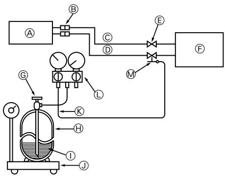
[Fig. 10-1] (P.8)
Indoor unit
Union
Liquid pipe
Gas pipe
E Stop valve
Outdoor unit
Refrigerant gas cylinder operating valve
Refrigerant gas cylinder for R410A with siphon
① Refrigerant (liquid)
① Electronic scale for refrigerant charging
Charge hose (for R410A)
① Gauge manifold valve (for R410A)
M Service port
- Connect gas cylinder to the service port of stop valve (3-way).
- Execute air purge of the pipe (or hose) coming from refrigerant gas cylinder.
- Replenish specified amount of refrigerant, while running the air conditioner for cooling.
Note:
In case of adding refrigerant, comply with the quantity specified for the refrigerating cycle.

Caution:
- Do not discharge the refrigerant into the atmosphere.
Take care not to discharge refrigerant into the atmosphere during installation, reinstallation, or repairs to the refrigerant circuit. - For additional charging, charge the refrigerant from liquid phase of the gas cylinder.
If the refrigerant is charged from the gas phase, composition change may occur in the refrigerant inside the cylinder and the outdoor unit. In this case, ability of the refrigerating cycle decreases or normal operation can be impossible. However, charging the liquid refrigerant all at once may cause the compressor to be locked. Thus, charge the refrigerant slowly.
To maintain the high pressure of the gas cylinder, warm the gas cylinder with warm water (under 40^ ) during cold season. But never use naked fire or steam.
[Fig. 8-10] (P.6) a [Fig. 8-19] (P.7)
[Fig. 8-10] (P.6) a [Fig. 8-19] (P.7)
@ A1dvTe TnV neppeia
① exwpiotn puthetaion
Kataxapiote evav exwpianto apithetao cuyouc o kthee eowtepiuovada ia va aeitoupyei kabe eoswepikn ova da an to diko nca aupmuato mlexeiipntio.
[Fig. 8-8] (P.5)
② Movāδɪkŋ puθμiən
Kataxpiote Tov iido apiBou 2euouc oAe cTic eawteipkec mova8c yia va aeitoupyoiv OAc i oawtepkec mva8c ano evaovadiko aapuato mXexipiatnio.
[Fig. 8-9] (P.5)
EeYxoc KWDIOU NOU EmuaviEaI aT Otv oOvN LCD.
Eav n ova 8ev mopei va aetoupnyoe kavoviká meta ano tic napanawdokiaotkec aetoupyie, avatpTe otov akolouo nivaka yia va biopwote tv artia.
@ Tpy6bI n3 Mei
© HenpaBnblHo
HepoBHO
6 PpaBnblHo
① Пов На К loHOM
f IMHeOTc3aYceHbI
CobJIOaI npabInbHocTb, OtpexKbTe MeHyTO Tpy6y npn IOMOOn Tpy6ope3a.
6.2.2. YdaJIeHnE 3aYceHneB
[Fig. 6-4] (P.3)
a3ayceHeu
3anaacha pa3BepTk
6 Tpyba n3 Mei
Tpy6ope3
-ПОЛНOCью удалие BCE заусеньы в ce�ени pa3pe3a trpy6bl.
B npouecce ydaene Hn 3ayeceHcB onyctnte KOHeu Tpy6bI Bn3, BO n36exHaNe nonadnHn B He 3ayeceHcB.
6.2.3.HabnHnuBaHne raikn
[Fig. 6-5] (P.3)
@ KoHcyHaRraika
⑥ Tpy6a n3 Mei
CHMIMTe C BYTpeHnero H npayXHO BO KOnOb KOnyChIbe raiKn H aDeHbTe IN Ha Tpyb, noNtocBIO ydaJIIN pR 3OTM 3ayCeHcbl. (HaDeTb raiKn NOcIe pa3BaIbUOBKn HE npeDCTaBNIETCRA BO3MOKbHM)
6.2.4. Pa3BaJbCuOBka
[Fig. 6-6] (P.3)
@ VHCTpyMeHT dIЯ pa3aBbUOBKN
© Tpyba n3 Meini
6 MyHdUTyK
@ KoHcyHaRraika
Cko6a
- Hnke onncbIbaeTc, KaK BblIOJHrTb pa3BaJIbObKy.
- Akkypatho BCTabnIte KpbIshky Do tex nop, noka He pa3dactc 3ByK ueJIyka. EcIn neJeuOK He pa3dactc, KpbIshka MoKet ynaCTb.
8.4.HapyxHbI 6Jok
[Fig. 8-20] (P.7)
- PpabnIbNo NOcOeINHInTe Ka6JIb OT BHyTpEnHero 6Joka K TepMHaJy BbIOB.
- IcnoIb3yIe ToT JKe TepMnHaN BbIbOIOB N IOnApHocTb, YTO IN B CInyae CBHyTpEHMM 6IOKOM.
ДдальншeroоблухиванследутпрдусмOTpeTBболшю длиHy coeMHHTelbHorO ka6eHЯ.
C 06oONKoHcOB coeHNHTeBHO KabeN (yDINHtE) HeoXOIMO CHaTb N3OJauHIO. Ecn KaebIb CnIshKom DInHHbI nn CoeHNHe 3a Cuet OTe3aHnI cepdueBnbl, CpexbTe N3OJauHc KabeN nITAHnHa BEnuHy, yKa3aHnHy o Ha pucyHke.
- He donyckaTte KOHTaKaTa CoeDHHTeIbHOro KaBela C TpyBaMn.
[Fig. 8-21] (P.7)
Ocna6bTe BnHTbKopo6Kn TepMHaJa
⑥ TepMInHaJI BbIBODoB
PoiKnIouaEmbI npBOoD
OctopoxHo:
-Будьтевнмателов,Вои3бекане owнбok пп рpoворke(Fig.8-21)
- Hadejxho 3aTAHnTe BnHTbI Kopo6Kn TepMnHaJa BO n36exHHe nx ocna6JeHH.
- Pocne 3aTJKKn CnerKa NotHIne 3a npoBoa n y6eIntecb, YTO OHn He DBrraIOTc.
IpeodocetepexeHne:
- Y6eDntecb, yTO cepBnchA naHelb HAdEJHo 3aKpeIeHa Ha HApuyKHom 6Ioke. HenpaBnJIbHOe 3aKpeIeHne KpbIuKNs 3JeKtpo6Ioka MoKet npNBecTn K NOxapy NIN NOPaXeHNo 3JeKtpuYeCKm TOKOM n3-3a nonadAHNr PbIJN, BODbl T.I.
- Hadejxho 3aTAHnte BnHTbI Kopo6Kn TepMHaJa.
- PpOboJa DOnJXHa 6bITb npObeHeTaKaIM o6pa3OM, YTO6bl NcKlnOHTb HataJxHeH pOboDob 3JIeKTponepeDaH.
B npTbHOM cnyae, MoKet BO3HKnHyt b Harpe Bn Bo3ropaHne.
8.5.HactpoKuФyHKcH
8.5.1 HactpoKaФункиьLOka(BbI6opФункиь6LOka)
1)ФУHKUЯ ABTOMATNUCHECKOTO BO3O5HOBJIENHA PABOTbl TOnIbKOДЯБecnpoBODHOrOpynIbTaДиCTAHUNHOу npaBNeHn [Fig.8-22] (P8) 3Ta moDeIb OcnaUeHaФYHKUeN ABTOMATNUCHECKOTO BO3O5HOBJIENHA PABOTbl
PnynpaBHeHn BHyTpEHnM 6IOKom C nylTa DnCTaHIOHORO ynpaBHeHn, pexm pa60tby, yctahOBHeHHa TEMpepAtya N CKOpOCTb BpaeeHnBEHTNlTota 3aHOcTcRb NamaTb Npim NOMoU cHTkA ynpaBHeHn BHYTpEHHero 6Ika. FyHKuN aBTOMATnueCKOro BO36OBHBeHn pa60t by ATOMaTHueeckn 3aNYCkaET 6Lok B MOMENT BO36OBHBeHn NODaun 3NeKtpOHePrn, NOcNE ee OTKIOHeHn.
8.5.2. HactpoJa yHKuN 6loKa (BbIbOp yHKuN 6loKa) [Fig. 8-22] (P.8)
IImeHHe NactpoKn nTaioJero HaprJxHn
Caliṣma lambasi yanip söner
This product is designed and intended for use in the residential, commercial and light-industrial environment.
The product at hand is based on the following EU regulations:
Low Voltage Directive 2006/95/ EC
- Electromagnetic Compatibility Directive 89/336/ EEC, 2004/108/ EC
Please be sure to put the contact address/telephone number on this manual before handing it to the customer.
- INSTALLATIONSHANDBUCH
- FÜR INSTALLATEURE
- MANUEL D'INSTALLATION
- POUR L'INSTALLATEUR
- 4
- 5
- 5.1
- 5.2
- 6.2
- 6.3
- 6.5
- 8.3
- 8.4
- Safety precautions
- Selecting the installation location
- Indoor unit
- Outdoor unit
- Symbols put on the unit
- Install the indoor unit on a ceiling strong enough to sustain its weight
- [Fig. 3-1] (P.2)
- Securing installation and service space
- Outdoor unit
- Ventilation and service space
- SUZ-KA25VA
- [Fig. 3-2] (P.2)
- Indoor unit accessories
- Fixing hanging bolts
- Fixing hanging bolts
- [Fig. 4-1] (P.2)
- Hanging structure
- Installing the unit
- Hanging the unit body
- [Fig. 5-1] (P.2)
- [Fig. 5-2] (P.2)
- Confirming the unit's position and fixing hanging bolts
- [Fig. 5-3] (P.2)
- Caution:
- Refrigerant pipe
- [Fig. 6-1] (P.3)
- Piping preparation
- Flaring work
- Pipe cutting
- [Fig. 6-3] (P.3)
- Burrs removal
- [Fig. 6-4] (P.3)
- Putting nut on
- [Fig. 6-5] (P.3)
- Flaring work
- [Fig. 6-6] (P.3)
- Check
- [Fig. 6-7] (P.3)
- Pipe connection
- [Fig. 6-8] (P.3)
- Warning:
- Outdoor unit connection
- Refrigerant pipe insulation
- [Fig. 6-9] (P.3)
- Cautions On Refrigerant Piping
- Purging procedures leak test
- Duct work
- Drain piping work
- [Fig. 6-10] (P.3)
- [Fig. 6-11] (P.3)
- [Fig. 7-1] (P.4)
- Power supply
- [Fig. 8-1] (P.4)
- Indoor wire connection
- Work procedure
- [Fig. 8-2-1] (P.4)
- [Fig. 8-2-2] (P.4)
- [Fig. 8-2-3] (P.4)
- [Fig. 8-2-4] (P.4)
- [Fig. 8-3] (P.5)
- Remote controller
- For wireless remote controller
- 1) Installing procedures
- Procure the following parts locally:
- [Fig. 8-4] (P.5)
- B-1. To lead the remote controller cord from the back of the controller:
- B-2. To run the remote controller cord through the upper portion:
- Signal Receiving Unit
- 1) Sample system connection
- [Fig. 8-5] (P.5)
- Connecting to Mr. SLIM air conditioner
- 2) Setting the pair number switch
- [Fig. 8-6] (P.5)
- Setting method
- Setting example
- Outdoor unit
- [Fig. 8-20] (P.7)
- Function settings
- Function setting on the unit (Selecting the unit functions)
- 1) AUTO RESTART FUNCTION
- For wireless remote controller only [Fig. 8-22] (P.8)
- Function setting on the unit (Selecting the unit functions) [Fig. 8-22] (P.8)
- Note:
- Function setting on the remote controller
- Function table
- Test run
- Before test run
- Do not use the air conditioner if the insulation resistance is less than 1.0M Insulation resistance
- Test run
- Using wireless remote controller
- [Fig. 9-1] (P.8)
- AUTO RESTART FUNCTION
- Indoor controller board
- Maintenance
- Gas charge
- [Fig. 10-1] (P.8)
- [Fig. 8-10] (P.6) a [Fig. 8-19] (P.7)
- [Fig. 8-8] (P.5)
- [Fig. 8-9] (P.5)
- YdaJIeHnE 3aYceHneB
- 6.2.3.HabnHnuBaHne raikn
- Pa3BaJbCuOBka
- 8.4.HapyxHbI 6Jok
- IpeodocetepexeHne:
- 8.5.HactpoKuФyHKcH
- HactpoKaФункиьLOka(BbI6opФункиь6LOka)
- HactpoJa yHKuN 6loKa (BbIbOp yHKuN 6loKa) [Fig. 8-22] (P.8)
Brand : MITSUBISHI
Model : SEZ-KD50VAL
Category : Air-conditioner