
SCENIC EDITION X102I - Desktop computer FUJITSU SIEMENS - Free user manual and instructions
Find the device manual for free SCENIC EDITION X102I FUJITSU SIEMENS in PDF.


User questions about SCENIC EDITION X102I FUJITSU SIEMENS
0 question about this device. Answer the ones you know or ask your own.
Ask a new question about this device
Download the instructions for your Desktop computer in PDF format for free! Find your manual SCENIC EDITION X102I - FUJITSU SIEMENS and take your electronic device back in hand. On this page are published all the documents necessary for the use of your device. SCENIC EDITION X102I by FUJITSU SIEMENS.
USER MANUAL SCENIC EDITION X102I FUJITSU SIEMENS
Are there any technical problems or other questions you need clarified?
Please contact:
The latest information and updates (e.g. BIOS update) on our mainboards can be found on the Internet under: http://www.fujitsu-siemens.com/mainboards
Y Bac ecTb TexHnueckne Bonpocbl nI np6JIembl?
ПосимВасобразибс:
K BaeweMy dInepy nIn B mara3nH, B KOtOpom Bbl npno6peyn yctpoiCTBO
K COTpydHnKAM HaSei ropuey IINHIn, yka3aHHoB KONTaKTHom fOpMynpe Ha caITe: www.fujitsu-siemens.com/support/contact/contact.html INN JKe, INJ 3aKa3uKOB, KOtOpBie KUnnn OTDeIbHyO MaTePunckU OINaTy, NO TelenfoHy: +49(0) 180 3777 005
AkyaJIbHyIO INHOpMaIuIO IO6HOBJIeHHbIe peJaKzIIN IporpAMM (HaIpymep, BIOS-Update) nIra HaIiX MATEPHNCKNX PnAT BbI haJIDeTe B INTEPHeTc HcaiTe: http://www.fujitsu-siemens.com/mainboards
Intel, Pentium and Celeron are registered trademarks of Intel Corporation, USA.
Microsoft, MS, MS-DOS and Windows are registered trademarks of Microsoft Corporation.
PS/2 and OS/2 Warp are registered trademarks of International Business Machines, Inc.
All other trademarks referenced are trademarks or registered trademarks of their respective owners, whose protected rights are acknowledged.
All rights, including rights of translation, reproduction by printing, copying or similar methods, even of parts are reserved.
Offenders will be liable for damages.
All rights, including rights created by patent grant or registration of a utility model or design, are reserved. Delivery subject to availability.
Right of technical modification reserved.
This manual has been printed on recycled paper.
Printed in the Federal Republic of Germany
AG 07/05
Ausgabe/Edition 2
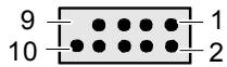
USB - dual channel (optional)
1 = VCC X
2 = VCCY
3 = Data negative X
4 = Data negative Y
5 = Data positive X
6 = Data positive Y
7 = GND
8 = GND
9 = Key
10 = Not connected
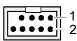
FireWire 1394 (optional)
4 = GND
5 = TPB+
6 = TPA-
7 = +12V
8= +12V
9 = Key
3=GND
10 = GND
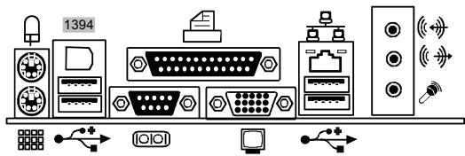
External connectors
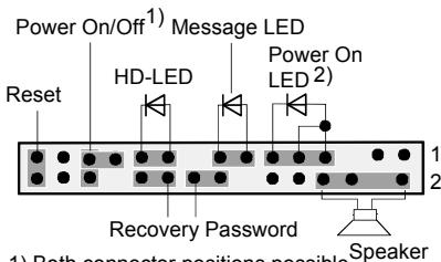
Front panel
1) Both connector positions possible
2) 2pin or 3pin connector possible
Recovery inserted = The system starts from floppy and allows a BIOS recovery
Password inserted = System- and BIOS Password are skipped when device is switched on




A26361-D2250-Z140-1-7619
| List of onboard features | D2250-A | D2250-F |
| Chipset | Intel® 915GL | Intel® 915GL |
| Board size | μATX | μATX |
| VGA | ✓ | ✓ |
| Audio / 8-channel / S/PDIF 5.1 | ✓ / - / - | ✓ / - / - |
| Buzzer / int. Speaker Support | ✓ / - | ✓ / - |
| LAN 1 Gbit / 100 Mbit / 10 Mbit | - / ✓ / ✓ | - / ✓ / ✓ |
| LAN ASF / AoL / WoL / Boot | - / - / ✓ / ✓ | - / - / ✓ / ✓ |
| Serial ATA / ATA / RAID | ✓ / ✓ / - | ✓ / ✓ / - |
| FireWire™ / USB 2.0 | - / ✓ | ✓ / ✓ |
| FAN monitored PSU** / CPU (FAN1) / FAN2 / FAN3 | - / - / - / - | - / - / - / - |
| FAN controlled PSU** / CPU (FAN1) / FAN2 / FAN3 | - / ✓ / - / - | - / ✓ / - / - |
| TEMP monitored CPU/ONB1/ONB2/OFFB | ✓ / - / - / - | ✓ / - / - / - |
| SmartCard SystemLock (USB / serial) | - / - | - / - |
| Fujitsu Siemens Computers Keyboard Power Button Support | - | - |
List of special onboard features
| Silent Fan / Silent Fan LT | - / √ | - / √ |
| System Guard / Silent Drives | - / √ | - / √ |
| Recovery BIOS / Desk Update / Multi Boot | ✓ / √ / √ | ✓ / √ / √ |
| Safe Standby / HDD Password | ✓ / - | ✓ / - |
| Logo Boot / Intel On Screen Branding | - / √ | - / √ |
** not supported by standard Power Supplies
| Special Features | |
| Silent Fan LT | Independent temperature related processor-fan supervision and control |
| Silent Drives | Noise reduction for optical and hard disk drives |
| Safe Standby | Prevents data loss in S3 (save-to-RAM) |
| Recovery BIOS | Restores a disrupted BIOS |
| Desk Update | Simple driver update with DU CD |
| Multi Boot | Comfortable boot from any boot device |
Power Supply Requirements - for onboard components (worst case)
| Source | Voltage | Maximal variation | Mainboard current (Maximal) |
| Main Power Supply | + 12 V | ± 5 % | 10.0 A |
| - 12 V | ± 10 % | 0.05 A | |
| + 5 V | ± 5 % | 6 A | |
| + 3.3 V | ± 5 % | 4 A | |
| Aux. Power Supply | + 5 V | ± 5 % | 2 A |
Mainboard D2250

Audioeingang (Line in), hellblau

Information about boards
Be sure to observe the following for boards with ESD:
- You must always discharge static build up (e.g. by touching a grounded object) before working.
The equipment and tools you use must be free of static charges. - Remove the power plug from the mains supply before inserting or removing boards containing ESDs.
Always hold boards with ESDs by their edges. - Never touch pins or conductors on boards fitted with ESDs.
An overview of the features is provided in the data sheet.
Special features
Your mainboard is available in different configuration levels. Depending on the configuration, your mainboard is equipped with or supports special features.
This manual describes the most important properties of this mainboard.
Additional information on mainboards is contained in the manual "Basic information on mainboard" on the "User Documentation" or "OEM Mainboard" CDs, or on the Internet.
Interfaces and connectors
The location of the interfaces and connectors of your mainboard is specified at the beginning of the manual.
The components and connectors marked are not necessarily present on the mainboard.
External ports
The location of the external connections of your mainboard is specified at the beginning of the manual.

PS/2 keyboard port, purple

Serial interface, turquoise

PS/2 mouse port, green

Parallel port/Printer, burgundy
LAN

LAN port (RJ-45)

Microphone jack (mono), pink

Monitor port, blue

USB - Universal Serial Bus, black

Audio input (Line in), light blue

Audio output (Line out), light green
1394
FireWire™, grey (optional)
Installing/removing or replacing processor (with heat sink)

Disconnect the system from the mains voltage before performing any of the tasks described below. Details are contained in the operating manual of your system.
Technical data
Intel Pentium 4 with 533 or 800 MHz front side bus in the LGA775 design (Value FMB 04A)
Intel Celeron with 533 MHz Front Side Bus in the LGA775 design
- A current list of the processors supported by this mainboard is available on the Internet at: www.fujitsu-siemens.com/mainboards.

Never touch the underside of the processor. Even minor soiling such as grease from the skin can impair the processor's operation or destroy the processor.
Place the processor in the socket with extreme care, as the spring contacts of the socket are very delicate and must not be bent.
If one or more spring contacts are bent do not insert the processor in any case as it may be damaged by doing so. Please contact the responsible vendor.
Remove the heat sink.

The processor socket ist covered with a protective cap to protect the spring contacts In a warranty case the mainboard can only be taken back by Fujitsu Siemens Computers with the protective cap secured!
Press down the lever and unhook it.
Fold up the frame.
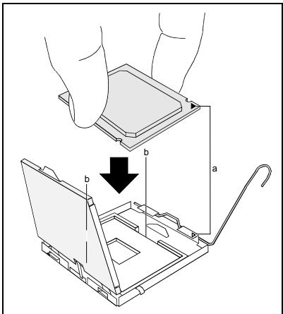
Hold the processor between your thumb and index finger and insert it into the socket (b) so that the marking of the processor is aligned with the marking on the socket (a).
Fold down the frame.
Press the lever downward until it is hooked in again.
Remove the protective cap and keep it.

Please note that, depending on the heat sink used, different heat sink mounts are required on the mainboard.
Depending on the configuration variant, you must pull a protective foil off the heat sink or coat the heat sink with heat conducting paste before fitting it.
Secure the heat sink - depending on the model - with four screws or push it into the mounts.
Installing/removing or replacing main memory
Technical data
Technology: DDR 333/400 SDRAM unbuffered DIMM modules
184-Pin; 2.5 V; 64 Bit, without ECC
Size:
| Mainboard D2250-A | 128 Mbyte to 2 Gbyte 333 DDR-SDRAM 128 Mbyte to 2 Gbyte 400 DDR-SDRAM |
| Mainboard D2250-F | 128 Mbyte to 4 Gbyte 333 DDR-SDRAM optional 128 Mbyte to 4 Gbyte 400 DDR-SDRAM optional |
Granularity: 128, 256, 512 or 1024 Mbyte for one socket
A current list of the memory modules recommended for this mainboard is available on the Internet at: www.fujitsu-siemens.com/mainboards.
At least one memory module must be installed. Memory modules with different memory capacities can be combined.

You may use unbuffered 2.5 V memory modules without ECC. DDR-DRAM memory modules must meet the PC2700 or PC3200 specification.
Additional technical data for D2250-F

If you use more than one memory module, then make sure to distribute the memory modules over both memory channels. By doing this you use the performance advantages of the dual-channel mode.
The maximum system performance is given when the same memory size is used in Channel A and Channel B.
To simplify equipping, the slots are colour coded.
With a memory configuration of 4 Gbytes the visible and usable main memory can be reduced down to 3.25 Gbytes (depending on the system configuration).

| Number of inserted memory modules | ||||
| slot to be used | 1 | 2 | 3 | 4 |
| Channel A, slot 1 | X | X | X | X |
| Channel A, slot 3 | X | X | ||
| Channel B, slot 2 | X | X | X | |
| Channel B, slot 4 | X | |||
The installation/removal is described in the "Basic information on mainboard" manual.
PCI bus interrupts - Selecting correct PCI slot
Extensive information on this section is contained in the manual "Basic information on mainboard".

To achieve optimum stability, performance and compatibility, avoid the multiple use of ISA IRQs or PCI IRQ Lines (IRQ sharing). Should IRQ sharing be unavoidable, then all involved devices and their drivers must support IRQ sharing.
PCI IRQ Lines connect PCI slots and onboard components to the interrupt controller. PCI IRQ Lines are permanently wired on the mainboard.
Which ISA IRQs are assigned to the PCI IRQ Lines is normally automatically specified by the BIOS (see "BIOS Setup" description).
Monofunctional expansions cards
Standard PCI expansion cards require a maximum of one interrupt, which is called the PCI interrupt INT A. Expansion cards that do not require an interrupt can be installed in any desired slot.
Multifunctional expansion cards or expansion cards with integrated PCI-PCI bridge
These expansion cards require up to four PCI interrupts: INT A, INT B, INT C, INT D. How many and which of these interrupts are used is specified in the documentation provided with the card.
The assignment of the PCI interrupts to the IRQ Lines is shown in the following table:
| PCI INT LINE | Controller or slot INT | ||||||||||||
| On board controller | Mechanical slot | ||||||||||||
| 1st | 2nd | 3rd | 4th | USB 2.0 | SMBus | Firewire | AC97 | LAN | PCIe x1 | 2 | 3 | 4 | |
| PCI slot | |||||||||||||
| 1 | 2 | 3 | |||||||||||
| 1 (A) | X | - | - | X | - | - | - | X | - | B | - | - | - |
| 2 (B) | - | - | - | - | - | X | - | - | - | C | - | - | - |
| 3 (C) | - | - | X | - | - | - | - | - | - | D | D | C | A |
| 4 (D) | - | X | - | - | - | - | - | - | - | A | C | D | B |
| 5 (E) | - | - | - | - | - | - | X | - | - | - | - | - | - |
| 6 (F) | - | - | - | - | - | - | - | - | - | - | B | A | C |
| 7 (G) | - | - | - | - | - | - | - | - | - | - | A | B | D |
| 8 (H) | - | - | - | - | X | - | - | - | X | - | - | - | - |
Use the first PCI slots that have a single PCI IRQ Line (no IRQ sharing). If you must use another PCI slot with IRQ sharing, check whether the expansion card properly supports IRQ sharing with the other devices on this PCI IRQ Line. The drivers of all cards and components on this PCI IRQ Line must also support IRQ sharing.
BIOS update
When should a BIOS update be carried out?
Fujitsu Siemens Computers makes new BIOS versions available to ensure compatibility to new operating systems, new software or new hardware. In addition, new BIOS functions can also be integrated.
A BIOS update should always also be carried out when a problem exists that cannot be solved with new drivers or new software.
Where can I obtain BIOS updates?
The BIOS updates are available on the Internet at www.fujitsu-siemens.com/mainboards.
How does a BIOS update work?
You have two ways of doing this:
- BIOS update under DOS with bootable BIOS update floppy disk - brief description
Download the update file from out website to your PC.
Insert an empty floppy disk (1.44 Mbyte).
Run the update file (e.g. 2250103.EXE).
A bootable update floppy disk is created. Leave this floppy disk in the drive.
Restart the PC.
Follow the instructions on screen.

Detailed information on the BIOS update under DOS is provided in the manual on "BIOS Setup" ("Drivers & Utilities" CD).
2. BIOS update under Windows with DeskFlash utility
A BIOS update can also be carried out directly under Windows with the DeskFlash utility. DeskFlash is contained on the "Drivers & Utilities" CD (under DeskUpdate).
Graphics port
Technical data
Function:
Intel GMA 900, 2D/3D graphics controller, Dynamic Video memory Technology, 400 Mhz integrated 24-bit RAMDAC
Screen resolution
Depending on the operating system used, the screen resolutions in the following table refer to the mainboard screen controller.
| Display resolution | Refresh rate (Hz) | Colour |
| 640 x 480 | 120 | 32 bit |
| 800 x 600 | 120 | 32 bit |
| 1024 x 768 | 100 | 32 bit |
| 1280 x 1024 | 100 | 32 bit |
| 1600 x 1200 | 100 | 16 bit |
| 1920 x 1440 | 75 | 16 bit |
| 2048 x 1536 | 75 | 16 bit |
Mainboard D2250

Yka3aHnI NO MOnyIaM
IopT KJIaBnaTpby PS/2, fnoJeToBbI

nocneoBaTeIbHbI INHTepFeic, 6npi03OBbl

AydnoBxOa (Line in), CBeTIO-cnHn

AydnoBbIXoD (Line out), CBeTNo-3eJIeHbI
1394
FireWire™, cebby (onzua)
MOnTaJ/DeMOHTaX IJIIN 3aMeHa IpoUeCCopoB (c paDnaTOpOM)

Дя осуцьпеня BCex onиcaHHbIX 3decb pa6ot BaIa cnCTema Длжна 6bIbT bIOJIHOCTbIO OTKIQUeHа OT cTeBOrO HanpЯЖeHЯ! BoIee NOdpo6Hy IOHΦopMauIIO 6bTOM Bы наДeTe BpyKOBoDCTBe no 3KcPnyaTaUIMn BaIe cnCTembl.
Texnueckne daHbie
Intel Pentium 4 c 533 i n 800 Mf C Front Side Bus B KOHCTpykTBHOM IcNoIHeH N LGA775 (Value FMB 04A)
Intel Celeron c 533 MfC Front Side Bus B KOHCTpyKTHBOM INCNOHEN LGA775
- Aktyальный сиюск поочеров, подержимьх STОМ Материнско Латов, Великий
В Исторе на саite: www.fujitsu-siemens.com/mainboards.

Hn B Koem clyuae He npikacaiTecb K HxhHei CTOpOHe npoecccopa. Yke MaJIeIne 3arp3HeHn, KaK Hanpimep, Xnp Ha KOxe, MOryT HeRaTnBHO cKa3aTbCra Ha pa6ote npoecccopa nn JKe pa3pyuHTb erO.
YcTaHaBnBaIte npoecccop B pa3bem OueHb OCTOpoxHO, NOCKOJIbKy npyXHHbIe KOHTaKtbl Ha pa3beMe OueHb YCbCTBnteJbHb I INx HeJIb3r N3r6aTb.
B TOM clyuae, ecn Odn Hnn HeckoJbKO npyKHHbIX KOHTAKTOB n30rHyTbI, HN B Kcem cnyae He yctaHabJbBaTe npoecccop, noCKoJIbKy n3-3a 3TORO OH MOKeT 6bITb NOBpeXdEh. IoxanyuCTa, opaNTteb HenocpeDCTBeHHo K KomTeHTHomy npoDaBuY.
UdaIte paIaNatop.

Pa3bem DnI npoecccopa 3aKpbIT 3aunTHoN pnaCTnHKo DnI 3aunTbI npyKnHHbIX KOHTaKOB. B cnyae npeBraBHeHn rapaHTnHbIX npTeH3N BO3BpaUaemar MaTePnHcKa PIIATA MOKeT 6bIT npInHrTa TOnbKO npi HAnuN npinKpeJIeHHo3 aunTHo NpactnKn qnpMbI Fujitsu Siemens Computers!
Haxmnte ha pbyar n noDnHmnte ero.
IopHMMTe yCtpoiCTBO KpeJIeHnBvEx.
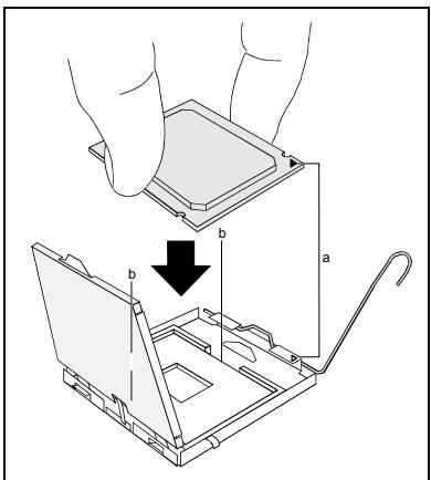
Держпглочьбсрбьшнmуka3aTeNBbIM naльцамиВставпетeroВразьem(b)ТК, YTOБы МаркИровка на поцeccope по Св氧му paСОЛОЖЕНЮ NOЛHOCью COВпала C МаркИровков на разьем(a).
Onycntte yctpoiCTBO KpeJIeHnBn3.
Haxmnte Ha pbyar Bn3 do uejka, 03haaouero, yTo npoceccop 3akpenneH.
YdaJIte 3aUHTHyIO pIacTHNky I coXpaHryTe ee.

IoxaJyNCTa,yuTbBaIteTO,HTOBA3aBcIMoCTnOTNCIOb3yeMOro paDnaTopaHa MaTePInHcKoPiNaTe Tpe6yIoTcpa3NIuHbIe yCtpoiCTBa KpeIIeHnpaDnaTopa.
B 3aBnCmOCTn OT BapnaHTa KOHcNgYpaunnepeyctaHOBKo paNaTopa BbdoJIkHb ChrTb 3aUHTHyIO pIeHKy c paNaTopa, nnn Je NOKpbItb paNaTOp TeplonpOBOJauei NaCTOn.
Ykpene panaTop (B 3aBcHmOCTn OT KOHfpyaun) npn NMOU qETbipex WypynOB nI INKe BCTaBte erO B KpeNek.
Mоnt tax/ДeMoHTax Илг 3ameha O3Y
Texnueckne daHbie
TexhJor: DDR 333/400 SDRAM moyun DIMM 6e3 byepeu3aui
184-Pin; 2,5 B; 64 6nt, 6e3 ECC
Obsumpa3mep:
| Mainboard D2250-A | DDR 333 SDRAM 128 MbaT - 2 ΓbaT DDR 400 SDRAM 128 MbaT - 2 ΓbaT |
| Mainboard D2250-F | DDR 333 SDRAM 128 MbaT - 4 ΓbaT (onця) DDR 400 SDRAM 128 MbaT - 4 ΓbaT (onця) |
Pa3mepbMoDynei: 128,256,512 nnn 1024 MbaaTob Ha kKaJdOM MoDyne
AkyaIbHbI CNICOK MOyJeN pAmrTn, peKOMeHNIOBaHNbIX dIЯ 3ToI MaTePHCKO IJIaTbI, Bbl NaIeTe B INTEPHeTe Ha caIte: www.fujitsu-siemens.com/mainboards.
HeoXoDIMO BCTpOHTb XOTy 6bl OOnH MoDyJIb NaMrtn. MoKHO KOM6uHnpOBaTb MoDyJIu NaMrtn c pa3nnuHoi EMKoCTbO 3Y.

Bo3MOxHO nCIOJIb3OBAHnE He6yΦepn3OBAHHbIX MoDyIe IamrTn 2,5 B 6e3 ECC.
MódyNJn namrTn DDR DIMM DOnJXHbI COOTBeTCTBOBaTb CneuΦnKauzn dIy PC2700 nIi PC3200.
DOnonHnTeIbHbIeTexHnueckne daHHbIe DnD2250-F

Ecni Bbl nCnoIb3yeTe 60JIbe OJHO rO MoyIy I naMyTn, CJeIte 3a Tem, YTO6bl MOyIy I naMyTn 6bln pacnPedeJIeHbI Ha 6obux KaHaIax C naMyTbIO. 3a Cuet 3toro Bbl 6yndeTe IcNoIb3oBaTb PneIMyuIeCTBa pa6OuX xapaKTEpcIeNk DByxKaHaIbHorO peKIma Dual- Channel-Mode.
MaKcImaHbHbIe pa6OuHne XapakTePncTnKIOCTnraHTcB TOM cIyuae,ecNHa KaHaJIax Channel A n Channel B nCnoJIb3yOTcMoDyUIn pAmrTc OndHaKOBbIMpa3MepaMn.
Port microphone, rose

Port moniteur, bleu

USB - Universal Serial Bus, noir

Entrée audio (Line in), bleu ciel

Sortie audio (Line out), vert clair
1394
FireWire™, gris (en option)