
ACR89U-A1 - Payment terminal ACS - Free user manual and instructions
Find the device manual for free ACR89U-A1 ACS in PDF.
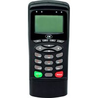


| Product Type | Payment terminal with smart card reader |
| Brand | ACS |
| Model | ACR89U-A1 |
| Interface | USB 2.0 Full Speed |
| Card Support | ISO 7816 Class A, B, C (5V, 3V, 1.8V) |
| SAM Slot | Yes, supports up to 2 SAM cards |
| Read/Write Speed | Up to 344 kbps |
| Operating System | Windows, Linux, Android (OTG) |
| Power Supply | USB bus-powered, no external adapter needed |
| Operating Temperature | 0°C to 50°C |
| Storage Temperature | -20°C to 70°C |
| Humidity | 5% to 95% non-condensing |
| Dimensions | Approx. 105 × 70 × 25 mm |
| Weight | Approx. 100 g |
| LED Indicators | Power and card detection |
| Security | PC/SC and CCID compliant, supports secure PIN entry |
| Maintenance | Wipe with dry soft cloth, avoid water and solvents |
| Repairability | Sealed design, no user-serviceable parts |
| Included Accessories | USB cable, user manual |
| Certifications | CE, FCC, RoHS |
Frequently Asked Questions - ACR89U-A1 ACS
User questions about ACR89U-A1 ACS
0 question about this device. Answer the ones you know or ask your own.
Ask a new question about this device
Download the instructions for your Payment terminal in PDF format for free! Find your manual ACR89U-A1 - ACS and take your electronic device back in hand. On this page are published all the documents necessary for the use of your device. ACR89U-A1 by ACS.
USER MANUAL ACR89U-A1 ACS


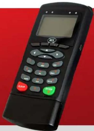
Reference Manual V1.05
Table of Contents
1.0. Introduction ....4
1.1. Document Overview 4
2.0. Hardware Design 5
2.1. Architecture....5
2.2. USB Interface 5
2.3. Communication Parameters 5
2.4. Endpoints....6
2.5. Contact Smart Card Interface....6
2.5.1. Smart Card Power Supply VCC (C1) 6
2.5.2. Card Type Selection....6
2.5.3. Interface for Microcontroller-based Cards....6
3.0. ACR89U-A1 USB Communication Protocol....7
3.1. Device Configuration 7
3.2. CCID Class-Specific Requests....8
3.2.1. Command Summary 8
3.3. CCID Command Pipe Bulk-Out Message....9
3.3.1. Command Summary 9
3.4. CCID Command Pipe Bulk-In Message 15
3.4.1. Message Summary 15
3.5. Extended Command Pipe Message Compatible with ACR89....18
3.5.1. Extended Command Pipe Bulk-OUT Message 18
3.5.2. Commands Detail....19
3.5.3. Extended Command Pipe Bulk-IN Message 26
3.5.4. Messages Detail....26
3.5.5. Extended Command Response Codes and Return States 28
3.6. CCID Interrupt-IN Message 30
3.6.1. Message Summary 30
3.7. CCID Error and Status Code 31
4.0. Dynamic Link Library (DLL)....32
4.1. ACR89 DLL API Declarations....32
4.1.1. Enumerators....32
4.1.2. Reader Command Data Structures....33
4.1.3. Reader Response Data 38
4.1.4. Reader Shared Command/Response Data Structures....39
4.2. ACR89 DLL API Functions 42
4.2.1. General Description 42
4.2.2. Port Functions 42
4.2.3. Device Functions....43
4.2.4. LCD Functions 46
4.2.5. Keypad Functions ....50
4.2.6. Real-time Clock Functions 52
4.2.7. Other Functions....54
Appendix A. Error Codes (DLL Errors) 56
List of Figures
Figure 1: ACR89U-A1 Architecture....5
Figure 2: CCID PC_to_RDR_Escape Message....18
Figure 3: PC_to_ACR89_DisplayGraphic – Bitmap Format ....21
Figure 4: CCID RDR_to_PC_Escape Message....26
Figure 5: Bitmap Format for ACR89 Reader....47
List of Tables
Table 1: USB Interface Wiring ....5
Table 2: CCID Error and Status Code....31
Table 3: Keypad Input Format....51
Table 4: DLL Error Codes....56
1.0. Introduction
This manual describes the use of ACR89 software programming interface to control the built-in accessories of the ACR89 multi-functional card reader. Built-in accessories are defined to be the keypad, LCD display, LEDs, buzzer and real-time clock, embedded in ACR89. Such components are not controlled through the smart card reader library.
There are two ways to control the ACR89 peripherals:
- PC/SC Escape command
The SCardControl() function of the PC/SC interface can be used to issue escape commands, which encapsulate the CCID command messages, to control the ACR89 peripherals.
- Dynamic link library (or DLL)
We will use the term ACR89 DLL to refer to this interface in the following text. The ACR89 DLL is based on the C programming language and is available on Windows 7, Vista, and XP. The name of the DLL is acr89.dll, and the functions described in this document can be found in acr89.h, the header file that exposes the functions to be used by applications.
1.1. Document Overview
- Section 3 discusses the PC/SC Escape Command to control the device peripherals. It also contains the ACR89 USB Communication Protocol for CCID command message definitions.
- Section 4 contains the ACR89 DLL (dynamic link library) API, which is completely independent of the PC/SC sub-system of Windows. The library does not use any PC/SC to communicate between ACR89 built-in peripherals and the application program as well.
2.0. Hardware Design
2.1. Architecture
The architecture of the ACR89 library can be visualized as the following diagram:
![graph TD A["Reader"] --> B["PC"] B --> C["Application"] B --> D["OS"] D --> E["CCID Layer"] E --> F["Application Program"] E --> G["DLL Program"] E --> H["Driver Program"] E --> I["Driver Program"] B --> J["PC/SC"] J --> K["acr89.dll"] J --> L["acr89fnc.sys"] J --> M["acr89bus.sys"]](/content/2026/07/1549702/images/ea9fa1858de4019397deede16157ef78213dae8c83a62b3e7887669ded0e004b.jpg)
Figure 1: ACR89U-A1 Architecture
2.2. USB Interface
The ACR89U-A1 is connected to a computer through USB following the USB standards.
2.3. Communication Parameters
The ACR89U-A1 is connected to a computer through USB as specified in the USB Specification 2.0, working in full speed mode, i.e., 12 Mbps.
| Pin Signal Function | ||
| 1 | VBUS | +5 V power supply for the reader |
| 2 | D- | Differential signal transmits data between ACR89U-A1 and PC |
| 3 | D+ | Differential signal transmits data between ACR89U-A1 and PC |
| 4 GND Reference voltage level for power supply | ||
Table 1: USB Interface Wiring
Note: In order for the ACR89U-A1 to function properly through the USB interface, the device driver should be installed.
2.4. Endpoints
The ACR89U-A1 uses the following endpoints to communicate with the host computer:
| Control Endpoint | - For setup and control purposes |
| Bulk OUT | - For commands to be sent from host to ACR89U-A1 (data packet size is 64 bytes) |
| Bulk IN | - For commands to be sent from ACR89U-A1 to host (data packet size is 64 bytes) |
| Interrupt IN | - For card status message to be sent from ACR89U-A1 to host (data packet size is 8 bytes) |
2.5. Contact Smart Card Interface
The interface between the ACR89U-A1 and the inserted smart card follows the specifications of ISO 7816-3 with certain restrictions or enhancements to increase the practical functionality of the ACR89U-A1.
2.5.1. Smart Card Power Supply VCC (C1)
The current consumption of the inserted card must not be higher than 50 mA.
2.5.2. Card Type Selection
Before activating the inserted card, the controlling PC always needs to select the card type through the proper command sent to the ACR89U-A1.
For MCU-based cards, the reader allows the selection of the preferred protocol, T=0 or T=1. However, this selection is only accepted and carried out by the reader through the PPS when the card inserted in the reader supports both protocol types. Whenever an MCU-based card supports only one protocol type, T=0 or T=1, the reader automatically uses that protocol type, regardless of the protocol type selected by the application.
2.5.3. Interface for Microcontroller-based Cards
For microcontroller-based smart cards, only the contacts C1 (VCC), C2 (RST), C3 (CLK), C5 (GND), and C7 (I/O) are used. A frequency of 4.8 MHz is applied to the CLK signal (C3).
3.0. ACR89U-A1 USB Communication Protocol
The ACR89U-A1 interfaces with the host (in PC-Linked mode) via a USB connection. CCID specifications have been released within the industry defining such a protocol for USB chip-card interface devices. CCID covers all the protocols required for operating smart cards and PIN. However, it does not define the protocol for operating other peripheral features that the ACR89U-A1 also has. The communication protocol for the ACR89U-A1 reader shall follow the CCID specifications and extend them to support the rest of the reader's features.
3.1. Device Configuration
The configurations and usage of USB end-points on ACR89U-A1 shall follow CCID Rev 1.1 session 4. An overview is summarized below:
- Control Commands are sent on control pipe (default pipe). These include class-specific requests and USB standard requests. Commands that are sent on the default pipe report information back to the host on the default pipe.
- CCID Events are sent on the interrupt pipe.
- CCID Commands are sent on BULK-OUT endpoint. Each command sent to ACR89 has an associated ending response. Some commands can also have intermediate responses.
- CCID Responses are sent on BULK-IN endpoint. All commands sent to ACR89 have to be sent synchronously. (i.e. bMaxCCIDBusySlots is equal to 1 for ACR89)
The supported CCID features by ACR89 are indicated in its Class Descriptor:
| Offset | Field | Size | Value | Description |
| 0 | bLength | 1 36h | Size of this descriptor, in bytes | |
| 1 | bDescriptorType | 1 21h | CCID Functional Descriptor type | |
| 2 | bcdCCID | 2 0100h | CCID Specification Release Number in Binary-Coded decimal | |
| 4 | bMaxSlotIndex | 1 04h | Five slots are available on ACR89. | |
| 5 | bVoltageSupport | 1 07h | ACR89 can supply 1.8 V, 3.0 V and 5.0 V to its slots. | |
| 6 | dwProtocols | 4 | 00000003h | ACR89 supports T=0 and T=1 Protocol |
| 10 | dwDefaultClock | 4 | 000012C0h | Default ICC clock frequency is 4.8 MHz |
| 14 | dwMaximumClock | 4 | 000012C0h | Maximum supported ICC clock frequency is 4.8 MHz |
| 18 | bNumClockSupported | 1 00h | Does not support manual setting of clock frequency | |
| 19 | dwDataRate | 4 | 003267h | Default ICC I/O data rate is 12,903 bps |
| 23 | dwMaxDataRate | 4 | 00032673h | Maximum supported ICC I/O data rate is 206,451 bps |
| 27 | bNumDataRatesSupported | 1 00h | Does not support manual setting of data rates | |
| 28 | dwMaxIFSD | 4 | 00000FEh | Maximum IFSD supported by ACR89 for protocol T=1 is 254 |
| 32 | dwSynchProtocols | 4 | 00000000h | ACR89 does not support synchronous card |
| 36 | dwMechanical | 4 | 00000000h | ACR89 does not support special mechanical characteristics |
| 40 | dwFeatures | 4 000204B2h | ACR89 supports the following features:Automatic parameter configuration based on ATR dataAutomatic ICC clock frequency change according to parametersAutomatic baud rate change according to frequency and FI, DI parametersAutomatic PPS made by the ACR89 according to the current parametersAutomatic IFSDShort APDU level exchange with ACR89 | |
| 44 | dwMaxCCIDMessageLength | 4 00000110h | Maximum message length accepted by ACR89 is 272 bytes | |
| 48 | bClassGetResponse | 1 FFh | Echo class of APDU in Get Response command | |
| 49 | bClassEnvelope | 1 FFh | Insignificant (Short APDU exchange level) | |
| 50 | wLCDLayout | 2 0815h 8 lines x 21 characters LCD | ||
| 52 | bPINSupport | 1 03h | ACR89 supports PIN Verification and PIN Modification | |
| 53 | bMaxCCIDBusySlots | 1 01h Only 1 slot can be simultaneously busy | ||
Note: Standard CCID adopts little endian mode.
3.2. CCID Class-Specific Requests
ACR89's USB communication with PC is based on command message format standard of ACR89 reader. This device shall support one CCID Class-Specific Request. Class-specific requests are sent via Control Pipe.
3.2.1. Command Summary
Stop any current processing command and return to a state where ACR89 is ready to accept a new command:
| bmRequestType | bRequest | wValue | wIndex | wLength | Data |
| 00100001B | ABORT(01h) | bSeq, bSlot | Interface | 0000h | None |
3.3. CCID Command Pipe Bulk-Out Message
The ACR89 reader follows the CCID Bulk-OUT Messages as standard CCID Rev 1.1 session 6.1. In addition, this specification defines some extended commands for operating additional features. This section lists the CCID Bulk-OUT Messages to be supported by ACR89. The extended commands will be introduced in Section 3.5.
3.3.1. Command Summary
3.3.1.1. PC_to_RDR_IccPowerOn
Activates the card slot and returns ATR from the card.
| Offset | Field | Size | Value | Description |
| 0 | bMessageType | 1 62h | - | |
| 1 | dwLength | 4 | 00000000h | Size of extra bytes of this message |
| 2 | bSlot | 1 | - | Identifies the slot number for this command |
| 5 | bSeq | 1 | - | Sequence number for command |
| 6 | bPowerSelect | 1 | - | Voltage that is applied to the ICC00h – Automatic Voltage Selection01h – 5 volts02h – 3 volts03h – 1.8 volts |
| 7 | abRFU | 2 | - | Reserved for future use |
The response to this message is the RDR_to_PC_DataBlock message and the data returned is the Answer To Reset (ATR) data.
3.3.1.2. PC_to_RDR_IccPowerOff
Deactivates the card slot.
| Offset | Field | Size | Value | Description |
| 0 | bMessageType | 1 63h | - | |
| 1 | dwLength | 4 | 00000000h | Size of extra bytes of this message |
| 5 | bSlot | 1 | - | Identifies the slot number for this command |
| 6 | bSeq | 1 | - | Sequence number for command |
| 7 | abRFU | 3 | - | Reserved for future use |
The response to this message is the RDR_to_PC_SlotStatus message.
3.3.1.3. PC_to_RDR_GetSlotStatus
Gets the current status of the slot.
| Offset | Field | Size | Value | Description |
| 0 | bMessageType | 1 65h | - | |
| 1 | dwLength | 4 | 00000000h | Size of extra bytes of this message |
| 5 | bSlot | 1 | - | Identifies the slot number for this command |
| 6 | bSeq | 1 - | Sequence number for command | |
| 7 | abRFU | 3 - | Reserved for future use |
The response to this message is the RDR_to_PC_SlotStatus message.
3.3.1.4. PC_to_RDR_XfrBlock
Transfers data block to the ICC.
| Offset | Field | Size | Value | Description |
| 0 | bMessageType | 1 6Fh - | ||
| 1 | dwLength | 4 | - | Size of abData field of this message |
| 5 | bSlot | 1 - | Identifies the slot number for this command | |
| 6 | bSeq | 1 - | Sequence | number for command |
| 7 | bBWI | 1 - | Used to extend the CCIDs Block Waiting Timeout for this current transfer. The CCID will timeout the block after “this number multiplied by the Block Waiting Time” has expired. | |
| 8 | wLevelParameter | 2 | 0000h | RFU (short APDU level) |
| 10 | abData | Byte array | - | Data block sent to the CCID. Data is sent “as is” to the ICC (short APDU level) |
The response to this message is the RDR_to_PC_DataBlock message.
3.3.1.5. PC_to_RDR_GetParameters
Gets the slot parameters.
| Offset | Field | Size | Value | Description |
| 0 | bMessageType | 1 | 6Ch | - |
| 1 | dwLength | 4 | 00000000h | Size of extra bytes of this message |
| 5 | bSlot | 1 - | Identifies the slot number for this command | |
| 6 | bSeq | 1 - | Sequence number for command | |
| 7 | abRFU | 3 - | Reserved for future use | |
The response to this message is the RDR_to_PC_Parameters message.
3.3.1.6. PC_to_RDR_ResetParameters
Resets slot parameters to default value.
| Offset | Field | Size | Value | Description |
| 0 | bMessageType | 1 | 6Dh | - |
| 1 | dwLength | 4 | 00000000h | Size of extra bytes of this message |
| 5 | bSlot | 1 - | Identifies the slot number for this command | |
| 6 | bSeq | 1 - | Sequence number for command | |
| 7 | abRFU | 3 - | Reserved for future use | |
The response to this message is the RDR_to_PC_Parameters message.
3.3.1.7. PC_to_RDR_SetParameters
Sets slot parameters.
| Offset | Field | Size | Value | Description |
| 0 | bMessageType | 1 61h - | ||
| 1 | dwLength | 4 | - | Size of extra bytes of this message |
| 5 | bSlot | 1 - | Identifies the slot number for this command | |
| 6 | bSeq | 1 - | Sequence number for command | |
| 7 | bProtocolNum | 1 - | Specifies what protocol data structure follows.00h = Structure for protocol T=001h = Structure for protocol T=1The following values are reserved for future use.80h = Structure for 2-wire protocol81h = Structure for 3-wire protocol82h = Structure for I2C protocol | |
| 8 | abRFU | 2 - | Reserved for future use | |
| 10 | abProtocolDataStructure | Byte array | - | Protocol Data Structure |
Protocol Data Structure for Protocol T=0 (dwLength=00000005h)
| Offset | Field | Size | Value | Description |
| 10 | bmFindexDindex | 1 - | B7-4 – FI – Index into the table 7 in ISO/IEC 7816-3:1997 selecting a clock rate conversion factorB3-0 – DI - Index into the table 8 in ISO/IEC 7816-3:1997 selecting a baud rate conversion factor | |
| 11 | bmTCCKST0 | 1 - | B0 – 0b, B7-2 – 000000bB1 – Convention used (b1=0 for direct, b1=1 for inverse)Note: The CCID ignores this bit. | |
| 12 | bGuardTimeT0 | 1 - | Extra Guardtime between two characters.Add 0 to 254 etu to the normal guardtime of 12etu. FFh is the same as 00h. | |
| 13 | bWaitingIntegerT0 | 1 | - | WI for T=0 used to define WWT |
| 14 | bClockStop | 1 - | ICC Clock Stop Support00h = Stopping the Clock is not allowed01h = Stop with Clock signal Low02h = Stop with Clock signal High03h = Stop with Clock either High or Low |
Protocol Data Structure for Protocol T=1 (dwLength=00000007h)
| Offset | Field | Size | Value | Description |
| 10 | bmFindexDindex | 1 - | B7-4 – FI – Index into the table 7 in ISO/IEC 7816-3:1997 selecting a clock rate conversion factorB3-0 – DI - Index into the table 8 in ISO/IEC 7816-3:1997 selecting a baud rate conversion factor | |
| 11 | BmTCCKST1 | 1 - | B7-2 – 000100bB0 – Checksum type (b0=0 for LRC, b0=1 for CRCB1 – Convention used (b1=0 for direct, b1=1 for inverse)Note: The CCID ignores this bit. | |
| 12 | BGuardTimeT1 | 1 - | Extra Guardtime (0 to 254 etu between two characters). If value is FFh, then guardtime is reduced by 1 etu. | |
| 13 | BWaitingIntegerT1 | 1 - | B7-4 = BWI values 0-9 validB3-0 = CWI values 0-Fh valid | |
| 14 | bClockStop | 1 - | ICC Clock Stop Support00h = Stopping the Clock is not allowed01h = Stop with Clock signal Low02h = Stop with Clock signal High03h = Stop with Clock either High or Low | |
| 15 | bIFSC | 1 - | Size of negotiated IFSC | |
| 16 | bNadValue | 1 00h | Only support NAD = 00h | |
The response to this message is the RDR_to_PC_Parameters message.
3.3.1.8. PC_to_RDR_Escape
This command allows ACR89 to use the extended features as defined in Section 3.5.
| Offset | Field | Size | Value | Description |
| 0 | bMessageType | 1 | 6Bh | - |
| 1 | DwLength | 4 - Size of abData field of this message | ||
| 5 | Bslot | 1 - Identifies the | slot number for this command | |
| 6 | Bseq | 1 - Sequence number for command | ||
| 7 | AbRFU | 3 - Reserved for future use | ||
| 10 | AbData | Byte array | - | Commands specified in Section 3.5.2 |
The response to this message is the RDR_to_PC_Escape message.
This message could return any of the following ACR89 specific errors. Further qualification of error is provided in the extended response.
| bmICCStatus | bmCommand Status | bError Description | |
| 3 1 ACR89_ERROR | ACR89 specific error. Refer to wReturnCode in ACR89 response | ||
| 3 1 INVALID_MODE | ACR89 is operating in a mode that does not support this command | ||
| 3 | 1 | DEVICE_VOID | ACR89 is not initialized. |
3.3.1.9. PC_to_RDR_Secure (RFU)
The command is reserved for future implementation.
This is a command message to allow entering the PIN for verification or modification on the card directly.
| Offset | Field | Size | Value | Description |
| 0 | bMessageType | 1 | 69h | - |
| 1 | DwLength | 4 | - | Size of extra bytes of this message |
| 5 | BSlot | 1 | - | Identifies the slot number for this command |
| 6 | BSeq | 1 | - Sequence number for command | |
| 7 | BBWI | 1 | - | Used to extend the CCIDs Block Waiting Timeout for this current transfer. The CCID will timeout the block after “this number multiplied by the Block Waiting Time” has expired. This parameter is only used for character level exchanges. |
| 8 | wLevelParameter | 2 | 0000h | RFU (short APDU level) |
| 10 | bPINOperation | 1 - | Used to indicate the PIN operation:00h = PIN Verification01h = PIN Modification02h = Transfer PIN from secure CCID buffer03h = Wait ICC response04h = Cancel PIN function05h = Re-send last I-Block, valid only if protocol in use is T=1.06h = Send next part of APDU, valid only if protocol in use is T=1. | |
| 11 | abPINDataStructure | Byte array | - | PIN Verification Data Structure or PIN Modification Data Structure |
The response to this message is the RDR_to_PC_DataBlock.
Note: Refer to standard CCID session 6.1.11 for detail PIN Verification Data Structure and PIN Modification Data Structure.
3.3.1.10. PC_to_RDR_Abort
This command is used with the Control pipe Abort request to tell the CCID to stop any current transfer at the specified slot and return to a state where the slot is ready to accept a new command pipe Bulk-OUT message.
| Offset | Field | Size | Value | Description |
| 0 | bMessageType | 1 72h - | ||
| 1 | DwLength | 4 | 00000000h | Size of extra bytes of this message |
| 5 | BSlot | 1 | - Identifies the slot number for this command | |
| 6 | BSeq | 1 | - Sequence number for command | |
| 7 | AbRFU | 3 | 000000h | RFU |
The response to this message is the RDR_to_PC_SlotStatus message.
3.4. CCID Command Pipe Bulk-In Message
The Bulk-IN messages are used in response to the Bulk-OUT messages. ACR89 shall follow the CCID Bulk-IN Messages as specified in standard CCID Rev 1.1 session 6.2. This section lists the CCID Bulk-IN Messages to be supported by ACR89.
This message is sent by ACR89 in response to PC_to_RDR_IccPowerOn, PC_to_RDR_XfrBlock and PC_to_RDR_Secure messages.
| Offset | Field | Size | Value | Description |
| 0 | bMessageType | 1 80h | Indicates that a data block is being sent from the CCID | |
| 1 | dwLength | 4 - | Size of abData field of this message | |
| 5 | BSlot | 1 - | Same value as in Bulk-OUT message | |
| 6 | BSeq | 1 - | Same value as in Bulk-OUT message | |
| 7 | bStatus | 1 - | Slot status and error register as defined in Section 3.7. | |
| 8 | bError | 1 - | Slot status and error register as defined in Section 3.7. | |
| 9 | bChainParameter | 1 | 00h | RFU (short APDU level) |
| 10 | AbData | Byte array | - | This field contains the data returned by the CCID |
3.4.1.2. RDR_to_PC_SlotStatus
This message is sent by ACR89 in response to PC_to_RDR_IccPowerOff, PC_to_RDR_GetSlotStatus, PC_to_RDR_Abort messages and class-specific ABORT request.
| Offset | Field | Size | Value | Description |
| 0 | bMessageType | 1 81h | - | |
| 1 | dwLength | 4 | 00000000h | Message-specific data length |
| 5 | BSlot | 1 | - | Same value as in Bulk-OUT message |
| 6 | BSeq | 1 - | Same value | as in Bulk-OUT message |
| 7 | bStatus | 1 - | Slot status and error register as defined in Section 3.7. | |
| 8 | bError | 1 - | Slot status and error register as defined in Section 3.7. | |
| 9 | bClockStatus | 1 - | Value:00h = Clock running01h = Clock stopped in state L02h = Clock stopped in state H03h = Clock stopped in an unknown stateAll other values are RFU. |
3.4.1.3. RDR_to_PC_Parameters
This message is sent by ACR89 in response to PC_to_RDR_GetParameters, PC_to_RDR_ResetParameters and PC_to_RDR_SetParameters messages.
| Offset | Field | Size | Value | Description |
| 0 | bMessageType | 1 82h - | ||
| 1 | dwLength | 4 - | Size of abProtocolDataStructure field of this message | |
| 5 | bSlot | 1 - | Same value as in Bulk-OUT message | |
| 6 | bSeq | 1 - | Same value as in Bulk-OUT message | |
| 7 | bStatus | 1 - | Slot status and error register as defined in Section 3.7. | |
| 8 | bError | 1 - | Slot status and error register as defined in Section 3.7. | |
| 9 | bProtocolNum | 1 - | Specifies what protocol data structure follows.00h = Structure for protocol T=001h = Structure for protocol T=1The following values are reserved for future use.80h = Structure for 2-wire protocol81h = Structure for 3-wire protocol82h = Structure for I2C protocol | |
| 10 | abProtocolDataStructure | Byte array | - | Protocol Data Structure as summarized in standard CCID Rev 1.1 session 6.2.3. |
3.4.1.4. RDR_to_PC_Escape
This message is sent by ACR89 in response to the PC_to_RDR_Escape message.
| Offset | Field | Size | Value | Description |
| 0 | bMessageType | 1 83h - | ||
| 1 | dwLength | 4 | - | Size of abData field of this message |
| 5 | bSlot | 1 | - | Same value as in Bulk-OUT message |
| 6 | bSeq | 1 | - | Same value as in Bulk-OUT message |
| 7 | bStatus | 1 | - | Slot status and error register as defined in Section 3.7 |
| 8 | bError | 1 | - | Slot status and error register as defined in Section 3.7 |
| 9 | bRFU | 1 00h RFU | ||
| 10 | abData | Byte array | - | Depending on its corresponding extended command, the data responded by ACR89 vary and are specified in Section 3.5.4. |
3.5. Extended Command Pipe Message Compatible with ACR89
This section defines the extended commands to be accepted by ACR89 for operating additional features that CCID does not cover. These commands are always executed under the command PC_to_RDR_Escape Bulk-Out message and responded with RDR_to_PC_Escape Bulk-IN message.
| PC Request Message | Code | ACR89 Response Message | Code |
| PC_to_ACR89_InputKey | 12h | ACR89_to_PC_DataBlock | 81h |
| PC_to_ACR89_SetCursor | 18h | ACR89_to_PC_DisplayStatus | 83h |
| PC_to_ACR89_SetBacklight | 19h | ACR89_to_PC_DisplayStatus | 83h |
| PC_to_ACR89_DisplayMessage | 1Bh | ACR89_to_PC_DisplayStatus | 83h |
| PC_to_ACR89_DisplayRowGraphic | 23h | ACR89_to_PC_DisplayStatus | 83h |
| PC_to_ACR89_SetContrast | 1Ch | ACR89_to_PC_DisplayStatus | 83h |
| PC_to_ACR89_ClearDisplay | 1Dh | ACR89_to_PC_DisplayStatus | 83h |
| PC_to_ACR89_ReadRTC | 08h | ACR89_to_PC_TimeStamp | 84h |
| PC_to_ACR89_SetRTC | 09h | ACR89_to_PC_TimeStamp | 84h |
| PC_to_ACR89_Buzzer | 0Ah | ACR89_to_PC_Echo | 90h |
| PC_to_ACR89_AccessEeprom | 21h | ACR89_to_PC_Datablock | 81h |
| PC_to_ACR89_SetLED | 22h | ACR89_to_PC_Echo | 90h |
| PC_to_ACR89_EraseSPIFlash | 30h | ACR89_to_PC_ExMemStatus | B0h |
| PC_to_ACR89_ProgramSPIFlash | 33h | ACR89_to_PC_MemoryStatus | B0h |
| PC_to_ACR89GetSPIFlash | 34h | ACR89_to_PC_MemoryPage | B1h |
| PC_to_ACR89_GetVersion | 36h | ACR89_to_PC_VersionInfo | B2h |
| PC_to_ACR89_Autholinfo | 38h | ACR89_to_PC_AuthInfo | B4h |
3.5.1. Extended Command Pipe Bulk-OUT Message
The command format defined in this section will be the abData field to be filled in the PC_to_RDR_Escape message.
Similar to the CCID message structure, the command format consists of a fixed length Command Header and a variable length Command Data portion. The command header is fixed to 5 bytes in length.
In contrast to CCID/USB practice, big endian will be adopted in the extended command portion.
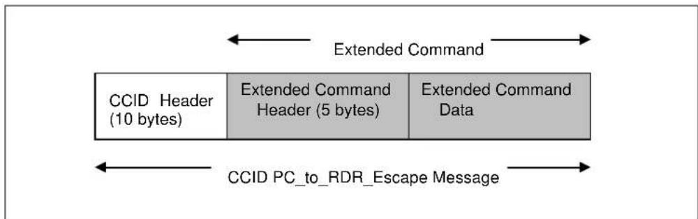
Figure 2: CCID PC_to_RDR_Escape Message
3.5.2. Commands Detail
3.5.2.1. PC_to_ACR89_InputKey
This command accepts key(s) input from the user using the keypad. This command context is slot independent.
| Offset | Field Name | Type | Size | Value | Description |
| 10 | BCmdCode | Hex 1 | 12h - | ||
| 11 | wCmdLength | Hex 2 | 0002h | Size of command data (in big endian) | |
| 13 | AbRfu | Hex 2 | 0000h | - | |
| 15 | bKeyInputMode | Bin 1 | - | B0 – Input mode (b0=0 for single key input, b0=1 for key string input). In key string input mode, the key string input is considered completed when “Enter” key is pressed.B1 – Keyboard mode (b1=0 for numeric input, b1=1 for alphanumeric input)B3 to b2 – Key display (b2=0 for key display disabled, b2=1 for key display enabled. When b2=1, b3=0 for key display as plaintext, b3=1 for key display as ‘*’)B4 – Key input timeout control (b4=0 for timeout enabled, b4=1 for timeout disabled)B5 – Secure key transfer (b5=0 for plaintext transfer, b5=1 for encrypted key transfer) This bit is reserved for future implementation.B6 – 0/1 – disable/enable control keyb7 – RFU | |
| 16 | bTimeoutValue | Hex 1 | - | Key input timeout time value counted in second. Effective only when key input timeout control bit of bKeyInputMode field is 0. |
The response to this command is the ACR89_to_PC_DataBlock message.
3.5.2.2. PC_to_ACR89_SetCursor
This command sets the LCD position cursor to a new position. This command context is slot independent.
| Offset | Field Name | Type | Size | Value | Description |
| 10 | BcmdCode | Hex | 1 | 18h | - |
| 11 | wCmdLength | Hex 2 | 0002h | Size of command data (in big endian) | |
| 13 | AbRfu | Hex | 2 | 0000 | Reserved for future |
| 15 | bRowPosition | Hex | 1 | 00h to 07h | New cursor row position |
| 16 | bColumnPosition | Hex 1 | 00h to 7Fh | New cursor column position |
The response to this command is the ACR89_to_PC_DisplayStatus message.
3.5.2.3. PC_to_ACR89_SetBacklight
This command configures the LCD display. This command context is slot independent.
| Offset | Field Name | Type | Size | Value | Description |
| 10 | BCmdCode | Hex | 1 | 19h | - |
| 11 | wCmdLength | Hex | 2 | 0001h | Size of command data (in big endian) |
| 13 | AbRfu | Hex | 2 | 0000 | Reserved for future |
| 15 | BBacklight | Hex | 1 | 00h or 01h | 00h = turns off backlight01h = turns on backlightOthers values RFU |
The response to this command is the ACR89_to_PC_DisplayStatus message.
3.5.2.4. PC_to_ACR89_DisplayMessage
This command displays a string of characters from ACR89 built-in font library. The string will be displayed horizontally from the current cursor position. ACR89 will automatically calculate the absolute coordinates from the character position and character size. The cursor will move accordingly. This command context is slot dependent.
| Offset | Field Name | Type | Size | Value | Description |
| 10 | BCmdCode | Hex | 1 | 1Bh | - |
| 11 | wCmdLength | Hex | 2 | Var... | Size of command data (in big endian) |
| 13 | AbRfu | Hex | 2 | 0000h | Reserved for future |
| 15 | bCharCoding | Hex | 1 | - | Data encoding format in abData field. Character size depends on data format. 00h = ASCII (1 row by 6 column per character) All other values are RFU |
| 16 | AbData | Ascii | Byte array | - | Character string of encoding format stated in bCharCoding field |
The response to this command is the ACR89_to_PC_DisplayStatus message.
3.5.2.5. PC_to_ACR89_DisplayRowGraphic
This command scans a row of graphics to be displayed on LCD.
| Offset | Field Name | Type | Size | Value | Description |
| 10 | bCmdCode | Hex 1 | 23h - | ||
| 11 | wCmdLength | Hex | 2 | Var... | Size of command data (in big endian) |
| 13 | abRfu | Hex 2 | 0000h | - | |
| 15 | bRowPosition | Hex 1 | - | Start position row index. One row is with height of 8 pixels. | |
| 16 | bColumnPosition | Hex | 1 | - | Start position column index |
| 17 | AbData | Hex | Var | - | Bitmap data of a row of the graphic to be displayed |
The sum of wCmdLength and bColumnPosition cannot exceed the column number of LCD (128).
| Row 7 | ...... | Row 2 | Row 1 | ||||||||||||||||||||||||||||||||||||||||||||||||||||||||||||||||||||||||||||||||||||||||||||||||||||||||||||||||||||||||||||||||||||||||||||||||||||||||||||||||||||||||||||||||||||||||||||||||||
| 0 | 1 | 2 | ...... | Column | 127 | ||||||||||||||||||||||||||||||||||||||||||||||||||||||||||||||||||||||||||||||||||||||||||||||||||||||||||||||||||||||||||||||||||||||||||||||||||||||||||||||||||||||||||||||||||||||||||||||||
| ... | 127 | ||||||||||||||||||||||||||||||||||||||||||||||||||||||||||||||||||||||||||||||||||||||||||||||||||||||||||||||||||||||||||||||||||||||||||||||||||||||||||||||||||||||||||||||||||||||||||||||||||||
Figure 3: PC_to_ACR89_DisplayGraphic - Bitmap Format
The response to this command is the ACR89_to_PC_DisplayStatus message.
3.5.2.6. PC_to_ACR89_SetContrast
This command sets the contrast level of the LCD. This command context is slot independent.
| Offset | Field Name | Type | Size | Value | Description |
| 10 | BCmdCode | Hex 1 | 1Ch - | ||
| 11 | wCmdLength | Hex 2 | 0001h | Size of command data (in big endian) | |
| 13 | abRfu | Hex | 2 | 0000 | Reserved for future |
| 15 | bContrastLevel | Hex | 1 | 00h to 63h | New LCD contrast level |
The response to this command is the ACR89_to_PC_DisplayStatus message.
3.5.2.7. PC_to_ACR89_ClearDisplay
This command clears one or more rows on the LCD display. The cursor will be moved to the position at the starting point of the cleared block after executing this command. This command context is slot independent.
| Offset | Field Name | Type | Size | Value | Description |
| 10 | BcmdCode | Hex | 1 | 1Dh | - |
| 11 | wCmdLength | Hex | 2 | 0002h | Size of command data (in big endian) |
| 13 | AbRfu | Hex | 2 | 0000h | Reserved for future |
| 15 | bClearMode | Hex 1 | 00h or 01h or 02h | 00h = Clear full screen01h = Clear the row located by the current position cursor02h = Clear some columns in a row starting from current position cursorAll other values RFU | |
| 16 | bNumber | - | 1 | - | For bClearMode = 01h – Number of rows to be clearedFor bClearMode = 02h – Number of columns to be clearedNot significant otherwise |
The response to this command is the ACR89_to_PC_DisplayStatus message.
3.5.2.8. PC_to_ACR89_ReadRTC
This command reads the current real time clock value from the built-in real time clock. The RTC increments the value every half second. This command context is slot independent.
| Offset | Field Name | Type | Size | Value | Description |
| 10 | BCmdCode | Hex 1 | 08h | - | |
| 11 | wCmdLength | Hex | 2 | 0000h | Size of command data (in big endian) |
| 13 | AbRFU | Hex | 2 | 0000h | - |
The response to this command is the ACR89_to_PC_TimeStamp message.
3.5.2.9. PC_to_ACR89_SetRTC
This command sets the real time clock value of the built-in real time clock to a specified value. This
command context is slot independent.
| Offset | Field Name | Type | Size | Value | Description |
| 10 | BCmdCode | Hex 1 | 09h - | ||
| 11 | wCmdLength | Hex | 2 | 0006h | Size of command data (in big endian) |
| 13 | AbRFU | Hex 2 | 0000h | - | |
| 15 | bRTCValue | BCD 6 | - | New real time clock value. Format in YY, MM, DD, HH, MI and SS |
The response to this command is the ACR89_to_PC_TimeStamp message.
3.5.2.10. PC_to_ACR89_Buzzer
| Offset | Field Name | Type | Size | Value | Description |
| 10 | BCmdCode | Hex | 1 | 0Ah | - |
| 11 | wCmdLength | Hex 2 | 0002h | Size of command data (in big endian) | |
| 13 | abRfu | Hex | 2 | 0000 | - |
| 15 | bBuzzerState | Hex 1 | 01h | 01h = Buzzer on00h = Buzzer off | |
| 16 | BbuzzerOnDuration | Hex 1 | - | Buzzer on duration in number of hundredth milliseconds.Effective only when bBuzzerState field is 01h.00h = Activate buzzer and do not turn off the bufferOther value = Activate buzzer for number of hundredth milliseconds and then turn off the buzzer |
The response to this command is the ACR89_to_PC_Echo message.
3.5.2.11. PC_to_ACR89_AccessEeprom
This command allows user write or read data from the EEPROM. Maximum allowed data length is 249 bytes.
| Offset | Field Name | Type | Size | Value | Description |
| 10 | bCmdCode | Hex | 1 | 21h | - |
| 11 | wCmdLength | Hex | 2 | Var... | Size of command data (in big endian) |
| 13 | AbRFU | Hex | 2 | 0000h | - |
| 15 | bAccessMode | Ascii | 1 | - | ‘W’ – write EEPROM‘R’ – read EEPROM |
| 16 | BDeviceNumber | Hex | 1 | - | 00 – Slave EEPROM01- Chinese Font EEPROM (Rfu) |
| 17 | AbAddress | Hex | 4 | - | Address of EEPROM (in big endian) |
| 21 | wDataLength | Hex 2 | Var... | Length of Data ( Write/Read ) (in big endian) | |
| 23 | bEeprom Data | Hex | Var.. | - | EEPROM data |
The response to this command is the ACR89_to_PC_DataBlock message.
3.5.2.12. PC_to_ACR89_SetLED
The command allows user to switch on/off of Power, slot1 and slot2 on card reader with color red and green.
| Offset | Field Name | Type | Size | Value | Description |
| 10 | BcmdCode | Hex | 1 | 22h | - |
| 11 | WcmdLength | Hex | 2 | 0003h | Size of command data (in big endian) |
| 13 | AbRFU | Hex | 2 | 0000h | - |
| 15 | Power LED | Hex 1 | - | Bit0 : 1- Selects Red colorBit1 : 1- Selects Green colorBit2 : 1- Selects Yellow colorBit7 : 0-OFF/1-ONE.g. Turn ON red color 10000001bTurn OFF green color 00000010blgnore xxxx0000b | |
| 16 | Slot1 LED | Hex 1 | - | Bit0 : 1- Selects Red colorBit1 : 1- Selects Green colorBit2 : 1- Selects Yellow colorBit7 : 0-OFF/1-ON | |
| 17 | Slot2 LED | Hex 1 | - | Bit0 : 1- Selects Red colorBit1 : 1- Selects Green colorBit2 : 1- Selects Yellow colorBit7 : 0-OFF/1-ON |
The response to this command is ACR89_to_PC_Echo.
3.5.2.13. PC_to_ACR89_EraseSPIFlash
This command erases flash blocks.
| Offset | Field Name | Type | Size | Value. | Description |
| 10 | bCmdCode | Hex | 1 | 30h | Command Code |
| 11 | bFlashType | Hex | 1 | 02h | SPI flash |
| 12 | bRFU | Hex | 1 | 00h | - |
| 13 | bStartBlockNum | Hex | 1 | - | Any number not zero, e.g. 01h |
| 14 | bEndBlockNum | Hex | 1 | - | Not less than bStartBlockNum |
The response to this command is the ACR89_to_PC_ExMemStatus message.
Note: The current size of one flash block is 64k bytes.
3.5.2.14. PC_to_ACR89_ProgramSPIFlash
This command writes 256 bytes data to a page of the SPI flash.
| Offset | Field Name | Type | Size | Value | Description |
| 10 | bCmdCode | Hex | 1 | 33h | Command Code |
| 11 | AbAddress | Hex 4 | xxxxxx00h | Start address of flash page (in little endian) | |
| 15 | AbData | Hex | 256 | - | Data write to a flash page |
| 271 | bCheckSum | Hex 1 | Checksum of AbData | ||
The response to this command is the ACR89_to_PC_ExMemStatus message.
3.5.2.15. PC_to_ACR89_GetSPIFlashPage
This command reads 256 bytes data from a page of the SPI flash.
| Offset | Field Name | Type | Size | Value | Description |
| 10 | bCmdCode | Hex | 1 | 34h | Command Code |
| 11 | AbAddress | Hex | 4 | xxxxxx00h | Start address of flash page (in little endian) |
The response to this command is the ACR89_to_PC_MemoryPage message.
3.5.2.16. PC_to_ACR89_GetVersion
This command reads boot loader or application firmware version information.
| Offset | Field Name | Type | Size | Value | Description |
| 10 | bCmdCode | Hex | 1 | 36h | Command Code |
| 11 | bVersionType | Hex 1 | - | 01h = boot loader version02h = application version | |
| 12 | AbRFU | Hex 3 | 000000h | - |
The response to this command is the ACR89_to_PC_VersionInfo message.
3.5.2.17. PC_to_ACR89_AuthInfo
This command reads RomID and RomData.
| Offset | Field Name | Type | Size | Value | Description |
| 10 | bCmdCode | Hex | 1 | 38h | Command Code |
| 11 | AbRFU | Hex | 16 | 00...00h | - |
The response to this command is the ACR89_to_PC_AuthInfo message.
3.5.3. Extended Command Pipe Bulk-IN Message
This section defines response messages to the extended commands returned by ACR89 for operating additional features that CCID does not cover. These messages are always responded using RDR_to_PC_Escape Bulk-IN message in standard CCID session 4.2.2.4.
The response format defined in this section will be the abData to be filled in the RDR_to_PC_Escape messages. Similar to CCID message structure, the response format consists of fixed length Response Header and variable length Response Data portion. The response header is fixed to 5 bytes in length. In contrast to CCID/USB practice, big endian will be adopted in extended response portion.
![graph LR A["CCID Header (10 bytes)"] --> B["Extended Response Header (5 bytes)"] B --> C["Extended Response Data"] D["CCID RDR_to_PC_Escape Message"] --> E style A fill:#ccc,stroke:#333 style B fill:#ccc,stroke:#333 style C fill:#ccc,stroke:#333 subgraph Extended Response direction LR A <--> D B <--…](/content/2026/07/1549702/images/fe62bcb2c13062d0757374aa0fe07909850b4295f72e13496e42f9a3e21ecbcd.jpg)
Figure 4: CCID RDR_to_PC_Escape Message
3.5.4. Messages Detail
3.5.4.1. ACR89_to_PC_DataBlock
This message is sent by ACR89 in response to PC_to_ACR89_InputKey commands.
For PC_to_ACR89_InputKey command, the data returned is the single key or key string captured from the keypad, depending on the key input mode chosen.
| Offset | Field Name | Size | Value | Description |
| 10 | BrespType | 1 81h - | ||
| 11 | WReturnCode | 2 - | Command | response code (in big endian) |
| 13 | WRespLength | 2 | Var... | Size of response data (in big endian) |
| 15 | Bdata | Var ... | - | This field contains the data returned by ACR89. |
3.5.4.2. ACR89_to_PC_DisplayStatus
This message is sent by ACR89 in response to PC_to_ACR89_DisplaySetCursor, PC_to_ACR89_DisplayMessage, PC_to_ACR89_DisplayRowGraphic and PC_to_ACR89_ClearDisplay commands.
| Offset | Field Name | Size | Value | Description |
| 10 | BrespType | 1 | 83h | - |
| 11 | wReturnCode | 2 | - | Command response code (in big endian) |
| 13 | wRespLength | 2 | 0002h | Size of response data (in big endian) |
| 15 | bRowPosition | 1 | 00h to 07h | Current cursor row position |
| 16 | bColumnPosition | 1 00h to 83h | Current cursor column position |
3.5.4.3. ACR89_to_PC_TimeStamp
This message is sent by ACR89 in response to PC_to_ACR89_ReadRTC and PC_to_ACR89_SetRTC commands.
| Offset | Field Name | Size | Value | Description |
| 10 | BRespType | 1 | 84h | - |
| 11 | wReturnCode | 2 | - | Command response code (in big endian) |
| 13 | wRespLength | 2 | 0006h | Size of response data (in big endian) |
| 15 | bTimeStamp | 6 | - | Current real time clock value. Format in YY, MM, DD, HH, MI and SS |
3.5.4.4. ACR89_to_PC_Echo
This message is sent by ACR89 in response to PC_to_ACR89_Buzzer, PC_to_ACR89_SetLED and PC_to_ACR89_ExitScriptMode commands.
| Offset | Field | Size | Value | Description |
| 10 | bRespType | 1 | 90h | - |
| 11 | wReturnCode | 2 9000h | Command response code, If command success, it returns 90 00h (in big endian) | |
| 13 | wRespLength | 2 | 0000 | Size of response data (in big endian) |
3.5.4.5. ACR89_to_PC_ExMemStatus
This message is sent by ACR89 in response to PC_to_ACR89_EraseSPIFlash, and PC_to_ACR89_ProgramSPIFlash command.
| Offset | Field Name | Size | Value | Description |
| 10 | bRespType | 1 | B0h | - |
| 11 | bReturnState | 1 | - | Command return state (please refer to later section) |
| 12 | bErrorCode | 1 | - | Error code (please refer to later section) |
| 13 | AbRFU | 2 | 0000h | - |
3.5.4.6. ACR89_to_PC_MemoryPage
This message is sent by ACR89 in response to PC_to_ACR89_GetSPIFlashPage commands.
| Offset | Field Name | Size | Value | Description |
| 10 | bRespType | 1 | B1h | - |
| 11 | bReturnState | 1 | - | Command return state (please refer to later section) |
| 12 | bErrorCode | 1 - | Error code (please refer to later section) | |
| 13 | AbRFU | 2 00 | 00h - | |
| 15 | AbData | 256 - | Data read from a flash page | |
| 271 | bCheckSum | Hex 1h Checksum of AbData | ||
Note: There will be no AbData and bCheckSum parts when command failed.
3.5.4.7. ACR89_to_PC_VersionInfo
This message is sent by ACR89 in response to PC_to_ACR89_GetVersion command.
| Offset | Field Name | Size | Value | Description |
| 10 | bRespType | 1 B2h | - | |
| 11 | bReturnState | 1 | - | Command return state (please refer to later section) |
| 12 | bErrorCode | 1 | - | Error code (please refer to later section) |
| 13 | wInfoLength | 2 | Var | Size of blinfoData (in little endian) |
| 15 | blinfoData | Var | - | Firmware version information (ASCII) |
Note: The wInfoLength is zero when there is no valid version information.
3.5.4.8. ACR89_to_PC_AuthInfo
This message is sent by ACR89 in response to PC_to_ACR89_AuthInfo commands.
| Offset | Field Name | Size | Value | Description |
| 10 | bRespType | 1 B4h | - | |
| 11 | bReturnState | 1 | - | Command return state (please refer to later section) |
| 12 | bErrorCode | 1 | - | Error code (please refer to later section) |
| 13 | AbRFU | 2 | 0000h | - |
| 15 | AbRomID | 8 | - | Unique ID |
| 23 | AbRFU | 48 | - | - |
Note: There will be no parts from offset 15 when command failed.
3.5.5. Extended Command Response Codes and Return States
The table summarizes the response code and the return states for the CCID extended commands used by ACR89.
| Response Code | Value | Description |
| CMD_OKAY | 9000h | Command executes successfully |
| INVALID_PARAMETERS FFFFh | Wrong parameters in the extended command. | |
| INVALID_COMMAND_CODE FFFEh | Command code in the extended command (offset 10) is invalid. | |
| INVALID_COMMAND_LENGTH | FFFDh | Wrong length in the extended command. |
| CANNOT_EXECUTE_COMMAND | FFFCh | Extended command cannot be executed. |
| TIMEOUT FFFBh | Timeout for executing the extended command. | |
| SCRIPT_ERROR | FFFAh | Cannot execute the script. |
| Return State Value Description | ||
| CMD_OK | 00h | Command executes successfully |
| CMD_FAIL | 01h | Command execution failed |
| Error Code | Value | Description |
| COMMAND_NOT_SUPPORT | 00h | Command code in the extended command (offset 10) is not supported. |
| HARDWARE_ERROR | 01h | Hardware error occurred. |
| ACCESS_DENIED | 02h | Function is denied according to current configuration. |
| ADDRESS_ERROR | 03h | Address parameter is not correct. |
| FRAME_ERROR | 04h | Command frame format is not correct. |
| CHECKSUM_ERROR | 05h | Check sum for data part is not correct. |
3.6. CCID Interrupt-IN Message
The Interrupt-IN endpoint is used to notify the host of events that may occur asynchronously and outside the context of a command-response exchange between host and ACR89. ACR89 shall follow the CCID Interrupt-IN Messages as specified in standard CCID Rev 1.1 session 6.3. This section lists the CCID Interrupt-IN Messages to be supported by ACR89.
3.6.1. Message Summary
3.6.1.1. RDR_to_PC_NotifySlotChange
This message is sent whenever ACR89 detects a change in the insertion status of an ICC slot.
| Offset | Field | Size | Value | Description |
| 0 | bMessageType | 1 50h - | ||
| 1 | bmSlotICCState | - - | This field is reported on byte granularity. The size is (2 bits * number of slots) rounded up to the nearest byte. Each slot has 2 bits. The least significant bit reports the current state of the slot (0b= no ICC present, 1b = ICC present). The most significant bit reports whether the slot has changed state since the last RDR_to_PC_NotifySlotChange message was sent (0b = no change, 1b = change). If no slot exists for a given location, the field returns 00b in those 2 bits.Example: A 3 slot CCID reports a single byte with the following format:Bit 0 = Slot 0 current stateBit 1 = Slot 0 changed statusBit 2 = Slot 1 current stateBit 3 = Slot 1 changed statusBit 4 = Slot 2 current stateBit 5 = Slot 2 changed statusBit 6 = 0bBit 7 = 0b |
3.7. CCID Error and Status Code
This section is the extension of standard CCID session 12 to tabulate the possible error codes to be used in conjunction with the slot error register in each Bulk-IN message. The table summarizes the CCID defined error codes and the additionally defined error codes for the extended commands used by ACR89.
| Error Name | Error Code | Possible Cause |
| CMD_ABORTED | FFh | Host aborted the current activity |
| ICC_MUTE | FEh | CCID timed out while talking to the ICC |
| XFR_PARITY_ERROR | FDh | Parity error while talking to the ICC |
| XFR_OVERRUN | FCh | Overrun error while talking to the ICC |
| HW_ERROR | FBh | An all-inclusive hardware error occurred |
| BAD_ATR_TS | F8h | - |
| BAD_ATR_TCK | F7h | - |
| ICC_PROTOCOL_NOT_SUPPORTED | F6h | - |
| ICC_CLASS_NOT_SUPPORTED | F5h | - |
| PROCEDURE_BYTE_CONFLICT | F4h | - |
| DEACTIVATED_PROTOCOL | F3h | - |
| BUSY_WITH_AUTO_SEQUENCE | F2h | Automatic Sequence Ongoing |
| PIN_TIMEOUT | F0h | - |
| PIN_CANCELLED | EFh | - |
| CMD_SLOT_BUSY | E0h | A second command was sent to a slot, which was already processing a command. |
| ACR89_ERROR | 10h | Error code defined in ACR89 response header instead of this error register. |
| DEVICE_VOID | 11h | ACR89 is not initialized. Either in manufacturer mode waiting for vendor personalization or the device has been tampered. |
| INVALID_SECRET_KEY | 12h | Wrong secret key is presented. |
| INVALID_MODE | 13h | Tried running a command that the current operation mode does not allow. |
| Reserved for future use | - | (All the rest unmentioned values) |
Table 2: CCID Error and Status Code
4.0. Dynamic Link Library (DLL)
ACR89 DLL is implemented as a library completely independent of the PC/SC sub-system of Windows. The library does not use any PC/SC to communicate between built-in accessories of ACR89 and the application program.
4.1. ACR89 DLL API Declarations
4.1.1. Enumerators
4.1.1.1. Port Numbers
enum
{
    AS_USB1 = 0x00,
    AS_USB2 = 0x01,
    AS_USB3 = 0x02,
    AS_USB4 = 0x03,
    AS_USB5 = 0x04,
    AS_USB6 = 0x05,
    AS_USB7 = 0x06,
    AS_USB8 = 0x07
};
Used by AS_Open to select the USB port where the ACR89 reader is connected. Up to eight USB ports can be selected.
4.1.1.2. LCD_CLEAR MODE
typedef enum _LCD_CLEAR_MODE {
    LCD_CLR_FULL = 0x00,
    LCD_CLR_ROWS = 0x01,
    LCD_CLR_COLS = 0x02
} LCD_CLEAR_MODE;
Used by AS_ClearLCDDisplay to select the mode for clearing the LCD display.
| Data Member | Value | Description |
| LCD_CLR_FULL | 00h | Clear the full LCD Screen |
| LCD_CLR_ROWS | 01h | Clear one or more rows of the LCD screen |
| LCD_CLR_COLS | 02h | Clear one or more columns of the LCD screen |
typedef enum _LED_OPTION {
    LED_UNCHANGED = 0x00,
    LED_OFF = 0x01,
    LED_RED = 0x02,
    LED_GREEN = 0x03,
    LED_YELLOW = 0x04
} LED_OPTION;
Used by AS_SetLED to set the color of one of the three LEDs on the ACR89.
| Data Member | Value | Description |
| LED_UNCHANGED | 00h | Do not change the color of the LED. |
| LED_OFF | 01h | Turn the LED off. |
| LED_RED | 02h | Switch the LED on and make it red. |
| LED_GREEN | 03h | Switch the LED on and make it green. |
| LED_YELLOW | 04h | Switch the LED on and make it yellow. |
4.1.1.3. EEPROM_ACCESS
typedef enum _EEPROM_ACCESS {
    READ_EEPROM = 0x00,
    WRITE_EEPROM = 0x01
} EEPROM_ACCESS;
Used by AS_AccessEEProm to select reading or writing from/to the internal EEPROM of the ACR89.
| Data Member | Value | Description |
| READ_EEPROM | 00h | Read data from the EEPROM |
| RITE_EEPROM | 01h | Write data from the EEPROM |
4.1.1.4. SERIAL_ACCESS
typedef enum _SERIAL_ACCESS {
    READ_SERIALFLASH = 0x00,
    WRITE_SERIALFLASH = 0x01,
    ERASE_SERIALFLASH = 0x02
} SERIALFLASH_ACCESS;
Used by AS_AccessSerialFlash to select reading, writing or erasing the internal Serial Flash of the ACR89.
| Data Member | Value | Description |
| READ_SERIALFLASH | 00h | Read data from the Serial Flash |
| WRITE_SERIALFLASH | 01h | Write data to the Serial Flash |
| ERASE_SERIALFLASH | 02h | Erase one block of Serial flash |
4.1.2. Reader Command Data Structures
4.1.2.1. KEYPADCONFIG
typedef struct _KEYPAD_CONFIG {
    BYTE cbMaxKeyString;
    BYTE KeyDisplayRow;
} KEYPADCONFIG, *PKEYPADCONFIG;
Used by AS_ConfigureKeyPad.
| Data Member | Value | Description |
| cbMaxKeyString | 00h to 0Fh | Maximum number of keys allowed for a key string in key string input mode (see Section 3.5.2.1 - PC_to_ACR89_InputKey command). |
| KeyDisplayRow | 00h to 03h | Starting row number on the LCD for displaying the keys input. |
4.1.2.2. KEYPADINPUT
typedef struct _KEYPAD_INPUT{
    BOOLEAN bEnableKeyString;
    BOOLEAN bEnableAlphanumeric;
    BOOLEAN bEnableKeyDisplay;
    BOOLEAN bEnableMaskedDisplay;
    BOOLEAN bDisableTimeout;
    BOOLEAN bEnableKeyEncryption;
    BOOLEAN bEnableControlKeys;
    BOOLEAN bReserved2;
    BYTE cbTimeout;
} KEYPADINPUT, *PKEYPADINPUT;
Used by AS_GetKeyInput.
| Data Member | Value | Description |
| BEnableKeyString | 0 or 1 | Input Mode0 – single key input1 – key string input (In key string input mode, the key string input is completed when the “Enter” key is pressed.) |
| BEnableAlphanumeric | 0 or 1 | Keyboard Mode0 – numeric input1 – alphanumeric input |
| BEnableKeyDisplay | 0 or 1 | Key Display Mode0 – key display disabled1 – key display enabled |
| BEnableMaskedDisplay | 0 or 1 | Key Masked Display Mode0 – key display as plaintext1 – key display as ‘*’ |
| BDisableTimeout | 0 or 1 | Enable or disable key input timeout0 – enable timeout1 – disable timeout |
| BEnableKeyEncryption | 0 or 1 | Secure key transfer0 – plaintext transfer1 – encrypted key transfer (RFU) |
| BEnableControlKeys | 0 or 1 | Enable of disable Control Keys (F1~F4 & directional keys)0 – disable control keys1 – enable control keys |
| bReserved2 | - RFU | |
| CbTimeout | 0 to 255 | Key input timeout time value counted in 100ms (e.g. 100 stands for 10 seconds). |
4.1.2.3. LCDCURSOR
typedef struct _LCD_CURSOR {
    BYTE cbRowPosition; // 0 - 7
    BYTE cbColPosition; // 0 - 83
} LCDCURSOR, *PLCDCURSOR;
Used in AS_SetLcdCursor to position the cursor position on the LCD screen.
| Data Member | Value | Description |
| cbRowPosition | 00h to 07h | Cursor row position |
| cbColPosition | 00h to 80h | Cursor column position |
4.1.2.4. LCDBACKLIGHT
typedef struct _LCD_BACKLIGHT {
    BOOLEAN bEnableBackL ight;
} LCDBACKLIGHT, *PLCDBACKLIGHT;
Used by AS_SetLcdBacklight to enable or disable the LCD backlight.
| Data Member | Value | Description |
| bEnableBackLight | 0 or 1 | 0 - turns off backlight1 - turns on backlight |
4.1.2.5. LCDGRAPHICS
typedef struct _LCD_GRAPHICS {
    LPCTSTR szBitmapFile;
} LCDGRAPHICS, *PLCDGRAPHICS;
Used by AS_SetLcdDisplayGraphics.
| Data Member | Value | Description |
| szBitmapFile | - | Full path to a Windows bitmap file to be displayed. The Dimension of the bitmap can be any size within a range of 128 pixels wide by 64 pixels high and the color depth can be 1-bit, 8-bit or 24-bit.Note: the LCD screen of the ACR89 only displays monochrome graphics. |
4.1.2.6. LCDMESSAGE
typedef struct _LCD_MESSAGE {
BYTE cbCharCoding;
LPCTSTR pMessage;
USHORT wMessageLen;
} LCDMESSAGE, *PLCDMESSAGE;
Used by AS_SetLcdDisplayMessage.
| Data Member | Value | Description |
| cbCharCoding | 00h | Data encoding format used in the pMessage field. Character size depends on data format. 00h – ASCIIAll other values are RFU |
| pMessage | ASCII String | Character string of encoding format stated in cbCharCoding field |
| wMessageLen | Positive Integer | The number of characters stored in pMessage |
4.1.2.7. LCDCONTRAST
typedef struct _LCD_CONTRAST {
BYTE cbContrastLe vel;
} LCDCONTRAST, *PLCDCONTRAST;
Used by AS_SetLcdSetContrast to set the contrast of the LCD screen.
| Data Member | Value | Description |
| cbContrastLevel | 00h to 63h | New LCD contrast level |
4.1.2.8. LCDCLEAR
typedef struct _LCD_CLEAR {
    BYTE cbClearMode;
    BYTE cbNumber;
} LCDCLEAR, *PLCDCLEAR;
Used by AS_ClearLcdDisplay to clear (part of) the LCD screen.
| Data Member | Value | Description |
| cbClearMode | LCD_CLEAR_MODE | LCD_CLR_FULL = Clear the complete LCD screenLCD_CLR_ROWS = Clear rowsLCD_CLR_COLS = Clear columns |
| cbNumber | LCD_CLR_ROWS | LCD_CLR_ROWS = Number of rows to be cleared *LCD_CLR_COLS = Number of columns to be cleared **Ignored in LCD_CLR_FULL mode. |
4.1.2.9. LED
typedef struct _LED {
    BYTE cbLedPower; // see LED_OPTION
    BYTE cbLedSlot1; // see LED_OPTION
    BYTE cbLedSlot2; // see LED_OPTION} LED, *PLED;
Used by AS_SetLED to control the LED's of the ACR89.
| Data Member | Value | Description |
| CbLedPower | LED_OPTION | Control the Power LEDLED_UNCHANGED – Do not change LEDLED_OFF – Turn LED offLED_RED – Turn LED redLED_GREEN- Turn LED greenLED_YELLOW – Turn LED yellow |
| cbLedSlot1 | LED_OPTION | Control the LED of card slot 1For possible options see LED_OPTION and above. |
| cdLedSlot2 | LED_OPTION | Control the LED of card slot 2For possible options see LED_OPTION and above. |
4.1.2.10. BUZZER
typedef struct _BUZZER {
    BYTE cbBuzzerState;
    BYTE cbBuzzerOnDuration;
} BUZZER, *PBUZZER;
Used in AS_SetBuzzer.
| Data Member | Value | Description |
| cbBuzzerState | 0 or 1 | 0 = Buzzer off1 = Buzzer on |
| cbBuzzerOnDuration | 0 - 255 | Duration of buzzer on counted in 100ms (e.g. 100 stands for 10 seconds). |
4.1.3. Reader Response Data
4.1.3.1. AS_STATUS
typedef struct _AS_STATUS {
    DLL_ERROR DllError;
    LONG W32Error;
} AS_STATUS;
| Data Member Value Description | ||
| DIIError | 00h – 20h | Contains the error code set by the DLL during command execution. See also Appendix A. |
| W32Error | Win32 Error Code | Contains the error code set by Windows system during the execution of Win32 API. |
4.1.3.2. INFO
typedef struct _INFO {
    CHAR szUID[8];
    CHAR szBootloaderVersion[64];
    CHAR szFirmwareSDKVersion[64];
} INFO, *PINFO;
Returned by AS_GetInfo, contains details of the ACR89 reader and its capabilities.
| Data Member | Value | Description |
| szUID | 8 bytes Unique ID of this device. Fixed 8 bytes | |
| szBootloaderVersion | 64 bytes ASCII | Bootloader version in ASCII, with null terminated |
| szFirmwareSDKVersion | 64 bytes ACSII | Firmware SDK version in ASCII, with null terminated |
4.1.3.3. KEYPADSTATUS
typedef struct _KEYPAD_STATUS {
    BYTE cbMaxKeyString;
    BYTE cbKeyDisplayMode;
} KEYPADSTATUS, *PKEYPADSTATUS;
Returned by AS_GetKeyPadConfig and AS_ConfigureKeyPad.
| Data Member | Value | Description |
| cbMaxKeyString | 0 – 255 | Maximum number of keys allowed for a key string in key string input mode (see AS_InputKey command). |
| cbKeyDisplayMode | 0 – 7 | Starting row number on the LCD for displaying the keys input. |
| Data Member | Value | Description |
| cbRowPosition | 0 - 7 | Current cursor row position |
| cbColumnPosition | 0 - 127 | Current cursor column position |
4.1.3.5. DATABLOCK
typedef struct _DATA_BLOCK {
    USHORT wDataLen;
    PBYTE pDataBlock;
} DATABLOCK, *PDATABLOCK;
Returned by nangi, contains the data returned by those functions.
| Data Member | Value | Description |
| wDataLen | - | The length of the size of pDataBlock before command execution. Stores the length of returned data block after command execution in ACR89. |
| pDataBlock | - | The data to input to a command or the data returned by ACR89. |
4.1.4. Reader Shared Command/Response Data Structures
4.1.4.1. TIMESTAMP
typedef struct _TIMESTAMP {
    CHAR szRTCValue[6];
} TIMESTAMP, *PTIMESTAMP;
Used in AS_ReadRTC and AS_SetRTC to retrieve or set the value of the run time clock of the ACR89.
| Data Member | Value | Description |
| szRTCValue[0] | 00 – 99 | Year (short format) |
| szRTCValue[1] | 1 – 12 Month | |
| szRTCValue[2] | 1 – 31 Day | |
| szRTCValue[3] | 1 – 23 Hours | |
| szRTCValue[4] | 0 – 59 Minutes | |
| szRTCValue[5] | 0 - 59 | Seconds |
4.1.4.2. ACCESSEEPROM
typedef struct _ACCESS_EEPROM {
BYTE cbFunction;
BYTE cbDeviceNumber;
DWORD dwAddress;
USHORT wDataLength;
PBYTE pData
} ACCESSEEPROM, *PACCESSEEPROM;
Used in AS_AccessEEPROM to read or write the data to the EEPROM memory of the ACR89.
| Data Member | Value | Description |
| cbFunction | EEPROM_ACCESS | 00h = READ_EEPROM01h = WRITE_EEPROM |
| cbDeviceNumber | 00h or 01h | 00h = Slave EEPROM01h = Chinese font EEPROM |
| dwAddress | 4 byte double word (hex) | Address of EEPROM |
| wDataLength | 2 byte word (hex) Length of Data (Write/Read) | |
| pData | Pointer to buffer of wDataLength | Read EEPROM: pointer to buffer to store the read EEPROM data.Write EEPROM: pointer to buffer containing data to write to EEPROM |
4.1.4.3. ACCESSSERIALFLASH
typedef struct _ACCESS_SERIALFLASH {
BYTE cbFunction;
DWORD dwAddress;
USHORT wDataLength;
PBYTE pData
} ACCESSSERIALFLASH, *PACCESSSERIALFLASH;
Used in AS_AccessSerialFlash to read, write or erase the data to the Serial Flash memory of the ACR89.
| Data Member | Value | Description |
| cbFunction | SERIALFLASH_ACCESS | 00h = READ_SERIALFLASH01h = WRITE_SERIALFLASH02h = ERASE_SERIALFLASH |
| dwAddress | 4 byte double word (hex) | Address of Serial Flash |
| wDataLength | 2 byte word (hex) | Read Serial Flash: Length of DataWrite Serial Flash: Length of DataErase Serial flash: Ignore |
| pData | Pointer to buffer of wDataLength | Read Serial Flash: pointer to buffer to store the read Serial Flash data.Write Serial Flash: pointer to buffer containing data to write to Serial FlashErase Serial flash: Ignore |
Notes:
- The area to write into must be erased first.
- The erase operation is in unit of block where the size of each block is 64 KB.
- For erase operation, only the higher significant two bytes is used. The low significant two bytes of the address is ignored. i.e. 64 KB address aligned.
4.2. ACR89 DLL API Functions
4.2.1. General Description
All functions return a status code AS_STATUS, which is a structure consisting of a DLL defined error and a WIN32 error. See also section 2.3.1 for more information about the AS_STATUS structure. Code AS_STATUS.DIIError == CMD_SUCCESS means success. AS_STATUS.W32Error is defined and used to provide additional error information to developers only when AS_STATUS.DIIError != CMD_SUCCESS. The API functions are classified into seven categories according to the type of accessories they will control as follows:
- Port Functions
- Device Functions
- LCD Functions
- Keypad Functions • Real-Time Clock Functions
- Script Functions
- Other Functions
4.2.2. Port Functions
4.2.2.1. AS_Open
This function opens a logical connection to ACR89. This function must be called before calling any other API function.
AS_STATUS AS_DECL AS_Open (
    IN INT nReaderType,
    IN INT nPort,
    OUT INT *nDevId);
Parameters:
| nReaderType | [in] Must be ACR89 (00h, as defined in acr89.h). |
| nPort | [in] The instance of the reader connected to USB port. E.g. AS_USB1 refers to the first connected ACR89 detected by the PC. See also Section 4.1.1.1 “Port Numbers” for possible options. |
| nDevId | [out] Handle to be returned upon successful creation of the connection. This handle will be used in all the subsequent calls to other API functions. |
Return Values
AS_STATUS This function returns different values depending on whether it succeeds or fails. AS_STATUS.DIIError contains the status as returned by the DLL. AS_STATUS.W32Error contains the Win32 error code associated with the DLL error, if any. See also Appendix A for the possible return codes.
Example:
INT nDid;
AS_STATUS status;

//open a connection to the ACR89
status = AS_Open(ACR89, AS_USB1, &nDid);
if(status.DllError == CMD_SUCCESS) {
    // connection success, do something with the ACR89
}
Else {
    // error occurred
    return status;
}
4.2.2.2. AS_Close
This function closes a logical connection to ACR89.
AS_STATUS AS_DECL AS_Close (IN INT nDevId);
Parameters
nDevId [in] Handle returned by a previous call to AS_Open.
Return Values
AS_STATUS This function returns different values depending on whether it succeeds or fails. AS_STATUS.DIIError contains the status as returned by the DLL. AS_STATUS.W32Error contains the Win32 error code associated with the DLL error, if any. See also Appendix A for the possible return codes.
Example:
INT nDid;
AS_STATUS status;

//open a connection to the ACR89
status = AS_Open(ACR89, AS_USB1, &nDid);
if(status.DllError == CMD_SUCCESS) {
    //connection success, do something
    .
    .
    .
    .
    //done, close connection
    status = AS_Close(nDid);
}
else {
    //error occurred
    return status;
}
4.2.3. Device Functions
Device Functions allow the initialization and retrieval of various parameters to and from the ACR89.
4.2.3.1. AS_GetInfo
This function retrieves general information of the ACR89.
AS_STATUS AS_DECL AS_GetInfo (
    IN INT nDevId,
    OUT PINFO pInfo);
Parameters:
nDevId [in] Handle returned by a previous call to AS_Open.
pInfo [out] Pointer to an INFO structure that saves the general information of the ACR89 device. See also Section 4.1.3.2 for more information about the INFO structure.
Return Values:
AS_STATUS
This function returns different values depending on whether it succeeds or fails. AS_STATUS.DIIError contains the status as returned by the DLL. AS_STATUS.W32Error contains the Win32 error code associated with the DLL error, if any. See also Appendix A for the possible return codes.
Example:
INT nDid;
INFO Info;
AS_STATUS status;

//open a connection to the ACR89
status = AS_Open(ACR89, AS_USB1, &nDid);
if(status.DllError == CMD_SUCCESS) {

    //connection success, get the reader information.
    status = AS_GetInfo(nDid, &Info);
    if (status.DLLError == CMD_SUCCESS) {
    //do something with the retrieved information
    }

    //close the connection
    status = AS_Close(nDid);
}
else {
    return status;
}
4.2.3.2. AS_AccessEEProm
This function allows the user to write or read data to/from the EEPROM. Maximum allowed data length is 256 bytes.
AS_STATUS AS_DECL AS_AccessEEPROM (
    IN INT nDevId,
    IN PACCESSEEPROM pEEPROM);
Parameters:
nDevId [in] Handle returned by a previous call to AS_Open.
pEEPRom [in] Pointer to an ACCESSEEPROM structure that contains the data to be written to ACR89 or the data read from the ACR89. See also Section 4.1.4.2 for more information about the ACCESSEEPROM structure.
Return Values:
AS_STATUS
This function returns different values depending on whether it succeeds or fails. AS_STATUS.DIIError contains the status as returned by the DLL. AS_STATUS.W32Error contains the Win32 error code associated with the
DLL error, if any. See also Appendix A for the possible return codes.
Example:
INT nDid;
ACCESSEEPROM eeprom;
BYTE aData[256];
AS_STATUS status;

//read the EEPROM data from address 0x0000
//assumed is a connection has already been established
eeprom.cbAccessMode = READ_EEPROM;
eeprom.wAddress = 0x0000;
eeprom.wDataLength = 0x0100;
eeprom.pData = aData;
status = AS_AccessEEPROM(nDid, &eeprom);
if (status.DLLError == CMD_SUCCESS) {
    //do something with the data read
}
else {
    //error occurred
}
return status;
4.2.3.3. AS_AccessSerialFlash
This function allows the user to write or read data to/from the serial flash. The maximum allowed data length is 256 bytes.
AS_STATUS AS_DECL AS_AccessSerialFlash (
    IN INT nDevId,
    IN PACCESSSERIALFLASH pSerialFlash);
Parameters:
nDevId [in] Handle returned by a previous call to AS_Open.
pSerialFlash [in] Pointer to an ACCESSSERIALFLASH structure that contains the data to be written to or read from the ACR89. See also Section 4.2.3.3 for more information about the ACCESSSERIALFLASH structure.
Return Values:
AS_STATUS
This function returns different values depending on whether it succeeds or fails. AS_STATUS.DIIError contains the status as returned by the DLL. AS_STATUS.W32Error contains the Win32 error code associated with the DLL error, if any. See also Appendix A for the possible return codes.
Example:
INT nDid;
ACCESSSERIALFLASH serialflash;
BYTE aData[256];
AS_STATUS status;

//read the EEPROM data from address 0x0000
//assumed is a connection has already been established
serialflash.cbAccessMode = READ_SERIALFLASH;
serialflash.wAddress = 0x0000;
serialflash.wDataLength = 0x0100;
serialflash.pData = aData;
status = AS_AccessEEPROM(nDid, &serialflash);
if (status.DLLError == CMD_SUCCESS) {
    //do something with the data read
}
else {
    //error occurred
}
return status;
4.2.4. LCD Functions
LCD Functions control the contrast, backlight status, and cursor position of the LCD panel. They are also used to display graphics and text on the LCD panel.
4.2.4.1. AS_SetLcdCursor
This function sets the LCD position cursor to a new position.
AS_STATUS AS_DECL AS_SetLcdCursor (
    IN INT nDevId,
    IN PLCDCURSOR pLcdCursor,
    OUT PDISPLAYSTATUS pDisplayStatus);
Parameters:
nDevId [in] Handle returned by a previous call to AS_Open.
pLcdCursor [in] Pointer to a LCDCURSOR structure that includes the cursor position to be set. See also Section 4.1.2.3 for more information about the LCDCURSOR structure.
pDisplayStatus [out] Pointer to a DISPLAYSTATUS structure that saves the newly set position parameters. See also Section 4.1.3.4 for more information about the DISPLAYSTATUS structure.
Return Values:
AS_STATUS This function returns different values depending on whether it succeeds or fails. AS_STATUS.DIIError contains the status as returned by the DLL. AS_STATUS.W32Error contains the Win32 error code associated with the DLL error, if any. See also Appendix A for the possible return codes.
Example:
LCDCURSOR lcdCursor;
DISPLAYSTATUS displayStatus;
AS_STATUS status;

//position the cursor at the upper left corner of the LCD
//assumed is a connection has already been established
lcdCursor.cbColPosition = 0;
lcdCursor.cbRowPosition = 0;

status = AS_SetLcdCursor(nDid, &lcdCursor, &displayStatus);
4.2.4.2. AS_SetLcdBacklight
This function turns the backlight of the LCD on or off.
AS_STATUS AS_DECL AS_SetLcdBacklight (
    IN INT nDevId,
    IN PLCDBACKLIGHT pLcdBacklight,
    OUT PDISPLAYSTATUS pDisplayStatus);
Parameters:
nDevId [in] Handle returned by a previous call to AS_Open.
pLcdBacklight [in] Pointer to a LCDBACKLIGHT structure that includes the cursor position parameters to be set. See also Section 4.1.2.4 for more information about the LCDBACKLIGHT structure.
pDisplayStatus [out] Pointer to a DISPLAYSTATUS structure containing the cursor position after the action. See also Section 4.1.3.4 for more information about the DISPLAYSTATUS structure.
Return Values:
AS_STATUS This function returns different values depending on whether it succeeds or fails. AS_STATUS.DIIError contains the status as returned by the DLL. AS_STATUS.W32Error contains the Win32 error code associated with the DLL error, if any. See also Appendix A for the possible return codes.
Example:
LCDBACKLIGHT lcdLight;
DISPLAYSTATUS lcdStatus;
AS_STATUS status;

//turn on the LCD backlight
//assumed is that a connection has already been established.
lcdLight.bEnableBackLight = TRUE;
status = AS_SetLcdBacklight(nDid, &lcdLight, &lcdStatus);
4.2.4.3. AS_SetLcdDisplayGraphic
This function transfers bitmap graphics to ACR89 and displays the graphics on the LCD from the current cursor position. The bitmap format is shown in the diagram (Figure 5). The cursor will be moved to the position next to the lower-right corner of the graphic after executing this command. The maximum dimensions for the bitmap are 128 pixels wide by 64 pixels high.
| Row 1 | Row 0 | ||||||
| BIT-MAP BYTE 1 | |||||||
| BIT-MAP BYTE 2 | |||||||
| MSB | LSB | ||||||
| BIT-MAP BYTE N | |||||||
Figure 5: Bitmap Format for ACR89 Reader
AS_STATUS AS_DECL AS_SetLcdDisplayGraphics (
    IN INT nDevId,
    IN PLCDGRAPHICS pLcdGraphics,
    OUT PDISPLAYSTATUS pDisplayStatus);
Parameters:
nDevId [in] Handle returned by a previous call to AS_Open.
pLcdGraphics [in] Pointer to a LCDGRAPHICS structure that specifies the path to the bitmap file. See also Section 4.1.2.5 for more information about the LCDGRAPHICS structure.
pDisplayStatus [out] Pointer to a DISPLAYSTATUS structure containing the cursor position after displaying the graphics. See also Section 4.1.3.4 for more information about the DISPLAYSTATUS structure.
Return Values:
AS_STATUS This functions returns different values depending on whether it succeeds or fails. AS_STATUS.DIIError contains the status as returned by the DLL. AS_STATUS.W32Error contains the Win32 error code associated with the DLL error, if any. See also Appendix A for the possible return codes.
Example:
LCDGRAPHICS lcdGrafx;
DISPLAYSTATUS lcdStatus;
AS_STATUS status;
//display a bitmap file called "MyLogo.bmp".
//assumed is that a connection has already been established.
lcdGrafx.szBitmapFile = "MyLogo.bmp";
status = AS_SetLcdDisplayGraphics(nDid, &lcdGrafx, &lcdStatus);
4.2.4.4. AS_SetLcdDisplayMessage
This function displays a string of characters using the ACR89 built-in font library. The string will be displayed horizontally from the current cursor position. ACR89 will automatically calculate the absolute coordinates from the character position and character size and the cursor will be moved accordingly. When the text reaches the end of a display line, the text will be wrapped.
AS_STATUS AS_DECL AS_SetLcdDisplayMessage (
    IN INT nDevId,
    IN PLCDMESSAGE pLcdMessage,
    OUT PDISPLAYSTATUS pDisplayStatus);
Parameters:
nDevId [in] Handle returned by a previous call to AS_Open.
pLcdMessage [in] Pointer to a LCDMESSAGE structure that specifies the alphanumeric text to be displayed on LCD. See also Section 4.1.2.6 for more information about the LCDMESSAGE structure.
pDisplayStatus [out] Pointer to a DISPLAYSTATUS structure containing the cursor position after displaying the message. See also Section 4.1.3.4 for more information about the DISPLAYSTATUS structure.
Return Values:
AS_STATUS
This function returns different values depending on whether it succeeds or fails. AS_STATUS.DIIError contains the status as returned by the DLL. AS_STATUS.W32Error contains the Win32 error code associated with the DLL error, if any. See also Appendix A for the possible return codes.
Example:
const char szText[]="Welcome to the ACR89";
LCDMESSAGE lcdMsg;
DISPLAYSTATUS lcdStatus;
AS_STATUS status;

//display the above text
//assumed is that a connection has already been established
lcdMsg.cbCharCoding = 0x00;
lcdMsg.pMessage = szText;
lcdMsg.wMessageLen = strlen(szText);
status = AS_SetLcdDisplayMessage(nDid, &lcdMsg, &lcdStatus);
4.2.4.5. AS_SetLcdSetContrast
This function sets the contrast level of the LCD.
AS_STATUS AS_DECL AS_SetLcdSetContrast (
    IN INT nDevId,
    IN PLCDCONTRAST pLcdContrast,
    OUT PDISPLAYSTATUS pDisplayStatus);
Parameters:
nDevId [in] Handle returned by a previous call to AS_Open. pLcdContrast [in] Pointer to a LCDCONTRAST structure that specifies the path to the bitmap file. See also Section 4.1.2.7 for more information about the LCDCONTRAST structure. pDisplayStatus [out] Pointer to a DISPLAYSTATUS structure containing the cursor position after displaying the graphics. See also Section 4.1.3.4 for more information about the DISPLAYSTATUS structure.
Return Values:
AS_STATUS This function returns different values depending on whether it succeeds or fails. AS_STATUS.DIIError contains the status as returned by the DLL. AS_STATUS.W32Error contains the Win32 error code associated with the DLL error, if any. See also Appendix A for the possible return codes.
Example:
LCDCONTRAST lcdContrast;
DISPLAYSTATUS lcdStatus;
AS_STATUS status;

//Set the contrast of the LCD to 100%
//assumed is that a connection has already been established
lcdContrast. cbContrastLevel = 0x3f;
status = AS_SetLcdSetContrast (nDid, &lcdContrast, &lcdStatus);
4.2.4.6. AS_ClearLcdDisplay
This function clears one or more rows or columns on the LCD display. The cursor will be moved to the position at the starting point of the cleared block after executing this command.
AS_STATUS AS_DECL AS_ClearLcdDisplay (
    IN INT nDevId,
    IN PLCDCLEAR pLcdClear,
    OUT PDISPLAYSTATUS pDisplayStatus);
Parameters:
nDevId [in] Handle returned by a previous call to AS_Open.
pLcdClear [in] Pointer to a LCDCLEAR structure that specifies the LCD clear mode. See also Section 4.1.2.8 for more information about the LCDCLEAR structure.
pDisplayStatus [out] Pointer to a DISPLAYSTATUS structure containing the cursor position after displaying the graphics. See also Section 4.1.3.4 for more information about the DISPLAYSTATUS structure.
Return Values:
AS_STATUS This function returns different values depending on whether it succeeds or fails. AS_STATUS.DIIError contains the status as returned by the DLL. AS_STATUS.W32Error contains the Win32 error code associated with the DLL error, if any. See also Appendix A for the possible return codes.
Example:
LCDCLEAR lcdClear;
DISPLAYSTATUS lcdStatus;
AS_STATUS status;

//clear the full LCD screen
//assumed is that a connection has already been established
lcdClear.cbClearMode = LCD_CLR_FULL;
lcdClear.cbNumber = 0x00; //ignored

status = AS_ClearLcdDisplay(nDid, &lcdClear, &lcdStatus);
4.2.5. Keypad Functions
Keypad Functions allow configuration of the keypad of ACR89 and handling of key input.
4.2.5.1. AS_GetKeyPadConfig (Definition of API is at preliminary stage)
This function reads the current configuration of the keypad of the ACR89.
AS_STATUS AS_DECL AS_GetKeyPadConfig (
    IN INT nDevId,
    OUT PKEYPADSTATUS pKeypadStatus);
Parameters:
nDevId [in] Handle returned by a previous call to AS_Open.
pKeypadStatus [out] Pointer to a KEYPADSTATUS structure that holds the current keypad configuration. See also Section 4.1.3.3 for more information about the KEYPADSTATUS structure.
Return Values:
AS_STATUS
This function returns different values depending on whether it succeeds or fails. AS_STATUS.DIIError contains the status as returned by the DLL. AS_STATUS.W32Error contains the Win32 error code associated with the DLL error, if any. See also Appendix A for the possible return codes.
4.2.5.2. AS_ConfigureKeyPad (Definition of API is at preliminary stage)
This function configures the keypad of the ACR89.
AS_STATUS AS_DECL AS_ConfigureKeyPad (
    IN INT nDevId,
    IN PKEYPADCONFIG pKeypadConfig,
    OUT PKEYPADSTATUS pKeypadStatus);
Parameters:
nDevId [in] Handle returned by a previous call to AS_Open.
pKeypadConfig [in] Pointer to KEYPADCONFIG structure that specifies keypad configuration to set in ACR89 keypad. See also Section 4.1.2.1 for more information about the KEYPADCONFIG structure.
pKeypadStatus [out] Pointer to KEYPADSTATUS structure that saves the current keypad configuration. See also Section 4.1.3.3 for more information about the KEYPADSTATUS structure.
Return Values:
AS_STATUS This function returns different values depending on whether it succeeds or fails. AS_STATUS.DIIError contains the status as returned by the DLL. AS_STATUS.W32Error contains the Win32 error code associated with the DLL error, if any. See also Appendix A for the possible return codes.
4.2.5.3. AS_GetKeyInput
This function enables key input on the ACR89. This can be single key input or string input depending on the options set in the KEYPADINPUT structure. The pressed keys will be returned in the following format:
| Mode Key Value | ||
| Numeric | 0 ~ 9 | 0 ~ 9 |
| Alphanumeric | 0 ~ 9 | ASCII code |
| All modes | Clear | 10h |
| Enter | 0Dh | |
| F1 3Dh | ||
| F2 3Eh | ||
| F3 | 3Fh | |
| F4 0Ch | ||
Table 3: Keypad Input Format
Notes:
When a function key is pressed while in string input mode, the input is cancelled and the function code is returned instead.
In string input mode, Enter will return the keys pressed and Clear will clear the last entered key.
In string input mode, when the inputted string has been cleared completely, AS_KeyInput will return with an empty string.
The direction keys will never be returned, but are only used for navigation of the cursor on the ACR89 LCD screen.
AS_STATUS AS_DECL AS_GetKeyInput (
    IN INT nDevId,
    IN PKEYPADINPUT pKeypadInput,
    OUT PDATABLOCK pDataBlock);
Parameters:
nDevId [in] Handle returned by a previous call to AS_Open.
pKeypadInput [in] Pointer to a KEYPADINPUT structure that specifies the options to use when ACR89 captures key input. See also section 2.2.3 for more information about the KEYPADINPUT structure.
pDataBlock [out] Pointer to a DATABLOCK structure that contains the pressed keys (if any). See also Section 4.1.3.5 for more information about the DATABLOCK structure.
Return Values:
AS_STATUS This function returns different values depending on whether it succeeds or fails. AS_STATUS.DIIError contains the status as returned by the DLL. AS_STATUS.W32Error contains the Win32 error code associated with the DLL error, if any. See also Appendix A for the possible return codes.
Example:
BYTE aKeys[16];
KEYPADINPUT kpInput;
DATABLOCK dataBlk;
AS_STATUS status;

//let the user input a string
//assumed is that a connection has already been established
dataBlk.pDataBlock = aKeys;
kpInput.bEnableKeyString = TRUE; //input a string
kpInput.bEnableAlphanumeric = TRUE; //string is alphanumeric
kpInput.bEnableKeyDisplay = TRUE; //display the keys on the LCD
kpInput.bEnableMaskedDisplay = FALSE; //no masking of the keys
kpInput.bEnableControlKeys = FALSE; //control keys disabled
kpInput.bDisableTimeout = 1; //no timeout
kpInput.bEnableKeyEncryption = 0; //no encryption of returned keys
status = AS_GetKeyInput(nDid, &kpInput, &data);
4.2.6. Real-time Clock Functions
The Real-time Clock Functions allow reading and setting of the built-in Run Time Clock of the ACR89.
4.2.6.1. AS_ReadRTC
This function reads the current real time clock value from the built-in real-time clock. The real-time clock increments the value every half second.
AS_STATUS AS_DECL AS_ReadRTC (
    IN INT nDevId,
    OUT PTIMESTAMP pTimeStamp);
Parameters:
nDevId [in] Handle returned by a previous call to AS_Open.
pTimeStamp [out] Pointer to TIMESTAMP structure that contains current time returned by the built-in real time clock of the ACR89. See also Section 4.1.4.1 for more information about the TIMESTAMP structure.
Return Values:
AS_STATUS This function returns different values depending on whether it succeeds or fails. AS_STATUS.DIIError contains the status as returned by the DLL. AS_STATUS.W32Error contains the Win32 error code associated with the DLL error, if any. See also Appendix A for the possible return codes.
Example:
AS_STATUS status;
TIMESTAMP tsRTC;
char szTime[81];

//read the RTC of the ACR89
//assumed is that a connection has already been established
status = AS_ReadRTC(nDevId, &tsRTC);
if(status.DllError == CMD_SUCCESS)
    // display the returned date & time from the ACR89
sprintf(szTime, "RTC: %d/%d/%d %d:%d:%d (yy/mm/dd hh:mm:ss)",
    tsRTC. szRTCValue[0], tsRTC. szRTCValue[1],
    tsRTC. szRTCValue[2], tsRTC. szRTCValue[3],
    tsRTC. szRTCValue[4], tsRTC. szRTCValue[5]);
    ::MessageBox(OL, szTime, "", MB_OK);
}
return status;

return status;
4.2.6.2. AS_SetRTC
This function sets the real time clock value of the built-in real time clock to the value specified in the TIMESTAMP structure.
AS_STATUS AS_DECL AS_SetRTC (
    IN INT nDevId,
    IN PTIMESTAMP pNewTime,
    OUT PTIMESTAMP pTimeStamp);
Parameters:
nDevId [in] Handle returned by a previous call to AS_Open.
pNewTime [in] Pointer to TIMESTAMP structure that contains the new time value to be set in the built-in real time clock. See also Section 4.1.4.1 for more information about the TIMESTAMP structure.
TIMESTAMP structure.
pTimeStamp [out] Pointer to TIMESTAMP structure that contains the newly set time value. See also Section 4.1.4.1 for more information about the TIMESTAMP structure.
Return Values:
AS_STATUS This function returns different values depending on whether it succeeds or fails. AS_STATUS.DIIError contains the status as returned by the DLL. AS_STATUS.W32Error contains the Win32 error code associated with the DLL error, if any. See also Appendix A for the possible return codes.
Example:
AS_STATUS status;
TIMESTAMP nowTime;
TIMESTAMP chkTime;
//set the RTC of the ACR89 using the values in the abTime array
//assumed is that a connection has already been established
CopyMemory(newTime.szRTCValue, abTime, 6);
Status = AS_SetRTC(pDevId, &newTime, &chkTime);
4.2.7. Other Functions
The following functions allow the user to control the buzzer and the LEDs of the ACR89.
4.2.7.1. AS_SetBuzzer
This function enables or disables the buzzer of the ACR89.
AS_STATUS AS_DECL AS_SetBuzzer (
    IN INT nDevId,
    IN PBUZZER pBuzzer);
Parameters:
nDevId [in] Handle returned by a previous call to AS_Open.
pBuzzer [in] Pointer to a BUZZER structure that contains the state to set for the buzzer. See also Section 4.1.2.10 for more information about the BUZZER structure.
Return Values:
AS_STATUS This function returns different values depending on whether it succeeds or fails. AS_STATUS.DIIError contains the status as returned by the DLL. AS_STATUS.W32Error contains the Win32 error code associated with the DLL error, if any. See also Appendix A for the possible return codes.
Example:
AS_STATUS status;
BUZZER buzStat;
//turn the buzzer of the ACR89 on for 1 second
//assumed is that a connection has already been established
buzStat.cbBuzzerState = 1;
buzStat.cbBuzzerOnDuration = 10; // 1 second
status = AS_SetBuzzer(nDevId, &buzStat);
return status;
4.2.7.2. AS_SetLed
This function enables or disables any of the LEDs of the ACR89.
AS_STATUS AS_DECL AS_SetLED (
    IN INT nDevId,
    IN PLED pLed);
Parameters:
nDevId [in] Handle returned by a previous call to AS_Open.
pBuzzer [in] Pointer to a LED structure that contains the state to set the LEDs of the ACR89. See also Section 4.1.2.9 LED for more information about the LED structure.
Return Values:
AS_STATUS
This function returns different values depending on whether it succeeds or fails. AS_STATUS.DIIError contains the status as returned by the DLL. AS_STATUS.W32Error contains the Win32 error code associated with the DLL error, if any. See also Appendix A for the possible return codes.
Example:
AS_STATUS status;
LED ledStat;

//turn on the LEDs and give them a different color
//assumed is that a connection has already been established
ledStat.cbLedPower = LED_RED; // Set the Power LED to red
ledStat.cbLedSlot1 = LED_GREEN; // Set the Slot1 LED to green
ledStat.cbLedSlot2 = LED_YELLOW; // Set the Slot1 LED to yellow
status = AS_SetLED(nDevId, &ledStat);

return status;
Appendix A. Error Codes (DLL Errors)
Only DLL Errors are listed below. For details of Win32 Errors, please refer to MSDN.
Error Code Error Description
| 00h CMD_SUCCESS |
| 01h CMD_WARNING_BUFFER_OVERFLOW |
| 02h CMD_ERROR_INVALID_OPTION |
| 03h CMD_ERROR_INVALID_PARAMETER |
| 04h CMD_ERROR_INVALID_RESPONSE_TYPE |
| 05h CMD_ERROR_INVALID_PARAMETER_LENGTH |
| 06h CMD_ERROR_LCD_INVALID_BITMAP_FILE |
| 07h CMD_ERROR_LCD_LOAD_BITMAP_FILE |
| 08h CMD_ERROR_LCD_INVALID_BITMAP_SIZE |
| 09h CMD_ERROR_BUFFER_TOO_SMALL |
| 0Ah CMD_ERROR_BUFFER_ALLOCATION_FAILED |
| 0Bh CMD_ERROR_COMM_PORT_OCCUPIED |
| 0Ch CMD_ERROR_COMM_PORT_CANNOT_OPEN |
| 0Dh CMD_ERROR_COMM_PORT_NOT_OPENED |
| 0Eh CMD_ERROR_COMM_PORT_WRITE |
| 0Fh CMD_ERROR_COMM_PORT_READ |
| 10h CMD_ERROR_COMM_DLL_GET_SYSTEMPATH |
| 11h CMD_ERROR_COMM_DLL_FAILED_LOAD |
| 12h CMD_ERROR_COMM_DLL_LOCATE_FUNCTION |
| 13h CMD_ERROR_COMM_DLL_GET_DEVINFO |
| 14h CMD_ERROR_COMM_DLL_INSUFF_BUFFER |
| 15h CMD_ERROR_COMM_DLL_GET_DEVDETAIL |
| 16h CMD_ERROR_COMM_NO_DEVICE_FOUND |
| 17h CMD_ERROR_SCRIPT_INVALID_FILE |
| 18h CMD_ERROR_SCRIPT_CANNOT_LOAD |
| 19h CMD_ERROR_TFM_UNSUPPORTED |
| 20h CMD_ERROR_SYSTEM_BUFFER_TOO_SMALL |
Table 4: DLL Error Codes



- TABLE OF CONTENTS
- INTRODUCTION
- HARDWARE DESIGN
- ACR89U-A1 USB COMMUNICATION PROTOCOL
- DYNAMIC LINK LIBRARY (DLL)
- APPENDIX A. ERROR CODES (DLL ERRORS)
- LIST OF FIGURES
- LIST OF TABLES
- DOCUMENT OVERVIEW
- ARCHITECTURE
- USB INTERFACE
- COMMUNICATION PARAMETERS
- ENDPOINTS
- CONTACT SMART CARD INTERFACE
- SMART CARD POWER SUPPLY VCC (C1)
- CARD TYPE SELECTION
- INTERFACE FOR MICROCONTROLLER-BASED CARDS
- DEVICE CONFIGURATION
- CCID CLASS-SPECIFIC REQUESTS
- COMMAND SUMMARY
- CCID COMMAND PIPE BULK-OUT MESSAGE
- PC_TO_RDR_ICCPOWERON
- PC_TO_RDR_ICCPOWEROFF
- PC_TO_RDR_GETSLOTSTATUS
- PC_TO_RDR_XFRBLOCK
- PC_TO_RDR_GETPARAMETERS
- PC_TO_RDR_RESETPARAMETERS
- PC_TO_RDR_SETPARAMETERS
- PC_TO_RDR_ESCAPE
- PC_TO_RDR_SECURE (RFU)
- PC_TO_RDR_ABORT
- CCID COMMAND PIPE BULK-IN MESSAGE
- RDR_TO_PC_SLOTSTATUS
- RDR_TO_PC_PARAMETERS
- RDR_TO_PC_ESCAPE
- EXTENDED COMMAND PIPE MESSAGE COMPATIBLE WITH ACR
- EXTENDED COMMAND PIPE BULK-OUT MESSAGE
- COMMANDS DETAIL
- PC_TO_ACR89_INPUTKEY
- PC_TO_ACR89_SETCURSOR
- PC_TO_ACR89_SETBACKLIGHT
- PC_TO_ACR89_DISPLAYMESSAGE
- PC_TO_ACR89_DISPLAYROWGRAPHIC
- PC_TO_ACR89_SETCONTRAST
- PC_TO_ACR89_CLEARDISPLAY
- PC_TO_ACR89_READRTC
- PC_TO_ACR89_SETRTC
- PC_TO_ACR89_BUZZER
- PC_TO_ACR89_ACCESSEEPROM
- PC_TO_ACR89_SETLED
- PC_TO_ACR89_ERASESPIFLASH
- PC_TO_ACR89_PROGRAMSPIFLASH
- PC_TO_ACR89_GETSPIFLASHPAGE
- PC_TO_ACR89_GETVERSION
- PC_TO_ACR89_AUTHINFO
- EXTENDED COMMAND PIPE BULK-IN MESSAGE
- MESSAGES DETAIL
- ACR89_TO_PC_DATABLOCK
- ACR89_TO_PC_DISPLAYSTATUS
- ACR89_TO_PC_TIMESTAMP
- ACR89_TO_PC_ECHO
- ACR89_TO_PC_EXMEMSTATUS
- ACR89_TO_PC_MEMORYPAGE
- ACR89_TO_PC_VERSIONINFO
- ACR89_TO_PC_AUTHINFO
- EXTENDED COMMAND RESPONSE CODES AND RETURN STATES
- CCID INTERRUPT-IN MESSAGE
- MESSAGE SUMMARY
- RDR_TO_PC_NOTIFYSLOTCHANGE
- CCID ERROR AND STATUS CODE
- ACR89 DLL API DECLARATIONS
- ENUMERATORS
- PORT NUMBERS
- LCD_CLEAR MODE
- EEPROM_ACCESS
- SERIAL_ACCESS
- READER COMMAND DATA STRUCTURES
- KEYPADCONFIG
- KEYPADINPUT
- LCDCURSOR
- LCDBACKLIGHT
- LCDGRAPHICS
- LCDMESSAGE
- LCDCONTRAST
- LCDCLEAR
- LED
- BUZZER
- READER RESPONSE DATA
- AS_STATUS
- INFO
- KEYPADSTATUS
- DATABLOCK
- READER SHARED COMMAND/RESPONSE DATA STRUCTURES
- TIMESTAMP
- ACCESSEEPROM
- ACCESSSERIALFLASH
- NOTES
- ACR89 DLL API FUNCTIONS
- GENERAL DESCRIPTION
- PORT FUNCTIONS
- AS_OPEN
- AS_CLOSE
- DEVICE FUNCTIONS
- AS_GETINFO
- EXAMPLE
- AS_ACCESSEEPROM
- AS_ACCESSSERIALFLASH
- LCD FUNCTIONS
- AS_SETLCDCURSOR
- AS_SETLCDBACKLIGHT
- AS_SETLCDDISPLAYGRAPHIC
- PARAMETERS
- RETURN VALUES
- AS_SETLCDDISPLAYMESSAGE
- AS_SETLCDSETCONTRAST
- AS_CLEARLCDDISPLAY
- KEYPAD FUNCTIONS
- AS_GETKEYPADCONFIG (DEFINITION OF API IS AT PRELIMINARY STAGE)
- AS_CONFIGUREKEYPAD (DEFINITION OF API IS AT PRELIMINARY STAGE)
- AS_GETKEYINPUT
- REAL-TIME CLOCK FUNCTIONS
- AS_READRTC
- AS_SETRTC
- OTHER FUNCTIONS
- AS_SETBUZZER
- AS_SETLED
Brand : ACS
Model : ACR89U-A1
Category : Payment terminal