
DYNAMICS 840 - Industrial vacuum cleaner NILFISK - Free user manual and instructions
Find the device manual for free DYNAMICS 840 NILFISK in PDF.
| Product type | Industrial vacuum cleaner |
| Brand | NILFISK |
| Model | DYNAMICS 840 |
| Power supply | 400 V three-phase, 4000 W |
| Filtration | Washable cartridge filter, class M |
| Tank capacity | 55 liters |
| Tank material | Stainless steel |
| Suction type | Dry and wet (depending on version) |
| Hose diameter | 40 mm |
| Cable length | 10 meters |
| Dimensions (L x W x H) | 620 x 520 x 850 mm |
| Weight | 55 kg |
| Noise level | 72 dB(A) |
| Year of manufacture | 1997 |
| Safety standards | CE, EN 60335-2-2, EN 60335-2-69 |
| Switch | On/Off |
| Level indicator | Fill level gauge |
| Clogging indicator | Filter clogging indicator |
| Included accessories | Floor nozzle, crevice nozzle, brush |
| Usage | Workshop, construction site, industry |
Frequently Asked Questions - DYNAMICS 840 NILFISK
User questions about DYNAMICS 840 NILFISK
0 question about this device. Answer the ones you know or ask your own.
Ask a new question about this device
Download the instructions for your Industrial vacuum cleaner in PDF format for free! Find your manual DYNAMICS 840 - NILFISK and take your electronic device back in hand. On this page are published all the documents necessary for the use of your device. DYNAMICS 840 by NILFISK.
USER MANUAL DYNAMICS 840 NILFISK
Before putting the cleaner into operation, be sure to also read the enclosed operating instructions thoroughly and keep them close at hand for future reference.
The cleaner may only be used by persons trained in its use and expressly authorised to use it.
GENERAL
Operation of this cleaner is subject to the applicable national regulations.
In addition to these operating instructions and the binding regulations on accident prevention applicable in the country of use, the generally acknowledged technical rules for safe and correct working must also be observed.
Any method of work endangering health or safety is forbidden!
HEALTH-ENDANGERING DUSTS*)
This cleaner is not suitable for picking up health-endangered dusts.
FIRE AND EXPLOSION HAZARD
The following materials must not be picked up with the cleaner:
Hot materials (glowing cigarettes, hot ashes, etc.)
Inflammable, explosive or aggressive fluids (e.g. petrol, solvents, acids, alkalines, etc.)
Inflammable, explosive dusts (e.g. magnesium or aluminium dust, etc.).
APPLIANCE PLUG SOCKET
Before connecting any appliance to the appliance plug socket, the cleaner must always be switched off.
If appliances are connected to the appliance plug socket, ensure that these appliances are also switched off when being connected to the appliance plug socket.
CAUTION!
The operating instructions and the safety precautions contained therein must be observed when using appliances connected to the appliance plug socket of the cleaner.
USING FOR THE FIRST TIME
Before using the cleaner for the first time, check that it is in a good and safe condition.
Plugs and connectors of mains leads must be at least splash water-proof.
Check the mains connection and mains plug.
Inspect the mains lead at regular intervals for damage or signs of ageing. Use the cleaner only when the mains lead is in a good and safe condition.
(Damaged mains leads present a danger of electric shocks!)
Use the cleaner only with an undamaged filter element.
DURING OPERATION
Take care not to damage the mains lead (e.g. by driving over, pinching or dragging). Pull out the mains plug only directly at the plug, i.e. not by pulling at the mains lead.
Before picking up liquids, the filter bag must be removed and the function of the float switch checked. If foaming is observed, stop work immediately and empty the tank.
MAINTENANCE AND REPAIR
CAUTION!
Before cleaning and servicing the cleaner, always remove the mains plug.
Carry out only maintenance operations described in these operating instructions. Use only original Wap spare parts.
Do not make any technical modifications to the cleaner.
CAUTION!
Your safety could be endangered as a result!
For all other maintenance and repair work, please contact the Wap Service department or an authorised specialist workshop!
ELECTRICAL EQUIPMENT
Check the rated voltage of the cleaner before connecting it to the mains power supply. Ensure that the voltage specified on the rating plate corresponds to the local mains voltage.
When connected to the mains power supply with a mains lead of type H 07 RN-F 3G 1.5 mm², the cleaner may also be used outdoors.
When using an extension lead or replacing the mains lead, the lead type specified by the manufacturer must always be used.
We recommend that the power supply to the cleaner be connected via an earth-leakage circuit breaker which interrupts the power supply either if the earth leakage current exceeds 30mA for 30 ms, or it contains an earthing test current circuit.
When using an extension lead, observe the minimum cross-sections of the leads:
| Cable length m | Cross-section mm2 |
| up to 20 | 1.5 |
| 20 to 50 | 2.5 |
Always arrange the current-carrying parts (plug sockets, plugs and connectors) and lay extension leads so that the protection class of the cleaner is maintained.
CAUTION!
Never spray the top section of the cleaner with water: Danger for persons, danger of short circuits.
The latest edition of the IEC Regulations must be observed.
1
2
3
4
5
6
7
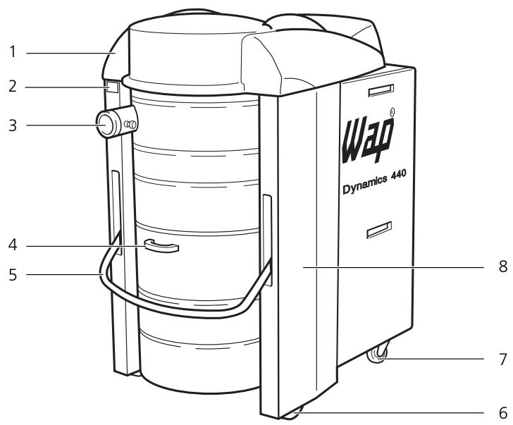
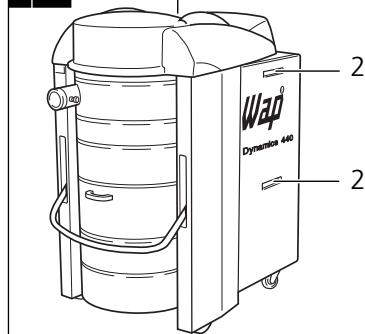
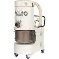
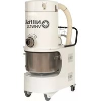
1 Description
1.1 Illustration
(Fig. 1)
1 Cover
2 Rating plate
3 Inlet fitting
4 Tank
5 Tank lock
6 Fixed castors
7 Swivel castors with brake
8 Chassis
9 Handle
10 Compressed-air connection
11 Power cable
12 Main switch
13 Fault lamp
14 Acoustic filter warning
15 Connection for automatic mode
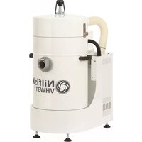
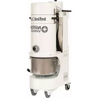
1.2 Application
The Dynamics 840 is an industrial vacuum cleaner of the usage class M and is thus suitable when used properly for vacuuming up dry, non-flammable dusts with a lower toxic limit >1mg / m^3 .
1.3 Inspections and approvals
Electrotechnically tested by the German SEV and TUV in accordance with the test methods/principles DIN VDE 0700 Part 1 DIN VDE 0700 Part 2 DIN VDE 0700 Part 205. Based on the test in accordance with DIN VDE 0700 Part 205, the vacuum cleaner is suitable for increased loading during commercial use.
The test as per DIN VDE 0700 Parts 1 and 205 showed that the technical safety requirements with regard to the electrical safety are also fulfilled when vacuuming up a water/air mixture.
Protection class 1
Protection type IF
Radio interference suppression level N
At a filter surface load ≤ 500m^3xm^-2xh^-1 the vacuum cleaner has a permeability < 0.5% and thus corresponds to the usage class "M" due to its other equipment.
The filter paper of the filter cartridge has been tested by the German BIA as per ZH 1/487, Para. 2. The mean permeability is certainly less than 0.1% at a velocity in blower stream of 0.05m / sec .
Electrotechnical tests must be conducted as per VDE 0105 in accordance with the regulations of the German Accident Prevention Regulation (VBG4) and as per DIN VDE 0701 Parts 1 and 3. These tests are required in accordance with DIN VDE 0702 at regular intervals and following servicing or changes.
1.4 Technical data
Dynamics 840
| Voltage | volts | 400 |
| Frequency | Hz | 50 |
| Power connection | 3-phase w/o neutral, clockwise phase sequence | |
| Connected load | watts | 2 x 4000 |
| Max. volume flow (air) | max. m³/h | 774 |
| max. l/min | 12900 | |
| Max. vacuum | max. hPa | 230 |
| Filter surface area | m² | 5 |
| Separating capacity | % | 99,95 |
| Filter blow-off | ||
| Compressed air | ||
| (oil and water-free) | bar | 8 |
| Measuring surface sound pressure level at 1 m distance as per DIN 45 635, Part 1 (4/84) in open field at maximum volume flow | dB(A) | 72 |
| Tank volume | l | 100 |
| Power cable | m | 5 |
| Suction hose diameter | mm | 70 |
| Width | mm | 750 |
| Depth | mm | 1250 |
| Height | mm | 1350 |
| Weight | kg | 245 |
| Protection class | 1 | |
| Protection type (splash-proof) | IP X4 | |
| Radio-interference suppression level | EN 50081 |
1.5 Accessories, additional equipment
Filter element Part No. 34931 "Special" filter element with non-stick coating Part No. 26736 Special accessories for automatic mode on request
Please see the "Accessories, Vacuum-Cleaner and Safety Vacuum-Cleaner Systems" chapter of our catalogue for the wide range of accessories available for this vacuum cleaner.
2 Use/Operation
2.1 Setting up vacuum cleaner
The vacuum cleaner must be set up on a firm surface. The surface must be able to safely support the weight of the vacuum cleaner and must be vibration-free.
CAUTION!
When setting up the vacuum cleaner, a minimum distance of 500mm must be maintained to the surrounding walls or objects.
CAUTION!
At an ambient temperature from 25^ C sufficient air circulation (cooling) must be provided at the set-up location.
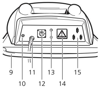
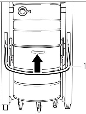
(Fig. 2)
- Set up vacuum cleaner at desired location.
- Lock swivel castors on vacuum cleaner by pressing brake (1).
2.2 Connecting suction hose
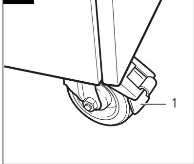
(Fig. 3)
Pull locking pin to connect or remove the suction hose.
2.3 Electrical connection
The operating voltage indicated on the rating plate must correspond to the mains voltage.
- Insert plug of power cable into a properly installed CEE outlet (clockwise phase sequence, connected load 3 x 16 A). Make sure vacuum cleaner is switched off.
2.4 Vacuuming
Never vacuum up flammable materials or liquids.
After vacuuming up liquids, the filter cartridge is damp. A damp filter cartridge can become blocked faster when dry materials are vacuumed up. For this reason the filter cartridge should be dried or replaced with a dry cartridge prior to dry vacuuming.
2.5 Operating vacuum cleaner
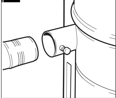
2.5.1 Before switching on
(Fig. 4)
Before switching the vacuum cleaner on, check whether the exhaust air outlet (1) is free and the cooling air inlet (2) of the motor is not covered or blocked and clear if necessary.
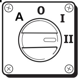
2.5.2 Switching vacuum cleaner on/off
Operate unit switch:
Switch position "l":
Vacuum cleaner runs with one turbine.
Switch position "II":
Vacuum cleaner runs with two turbines.
NOTE!
First run vacuum cleaner in position "I", then switch to position "II".
Switch position "A":
Vacuum cleaner in automatic mode.
Control voltage 24 V DC - safety extra-low voltage.
NOTE!
If no vacuum power is required, the vacuum cleaner is in the wait mode, i.e. no turbine runs.
2.6 Following work
Switch position "0":
Vacuum cleaner is switched off.
If the vacuum cleaner is not required for a longer period of time, pull the mains plug out of the electrical outlet.
3 Care/Maintenance
3.1 Important safety precautions

CAUTION!
Always pull out the mains plug before performing cleaning or maintenance work on the vacuum cleaner.
Only carry out maintenance work described in these operating instructions and use only genuine WAP spare parts.
Do not make any technical changes to the vacuum cleaner.
CAUTION!
Changes of this type could endanger your safety.
Please contact Wap Customer Service or an authorised workshop for further maintenance and repair work.
3.2 Maintenance schedule
| Activity | As required Monthly | |
| 3.3 Emptying tank | ● | |
| 3.4.1 Blowing off filter | ● | |
| 3.4.2 Replacing filter element | ● |
3.3 Emptying tank
(Fig. 6)
- Switch off vacuum cleaner by setting main switch to "0" position.
- Swing bar (1) of tank lock upward; tank is lowered.
- Roll out tank (2).
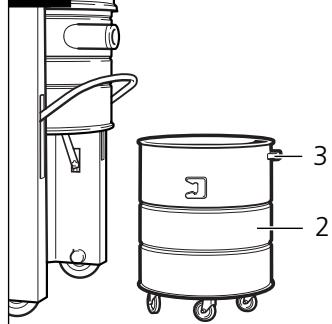
(Fig. 7)
- Dispose of tank content in accordance with legal regulations.
- Roll in tank (2). Handle (3) must face toward front.
- Swing bar (1) of tank lock downward; tank is raised and locked.
3.4 Filter element
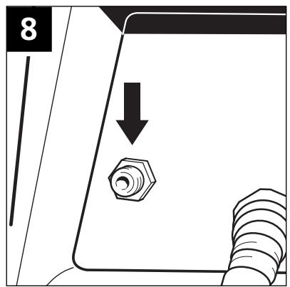
3.4.1 Blowing off filter
(Fig. 8)
With vacuum cleaner switched on:
- Connect compressed-air hose to connection with quick coupling and leave connected for approx. 10 seconds, then remove compressed-air hose again.
Compressed air: Maximum 8 bar.
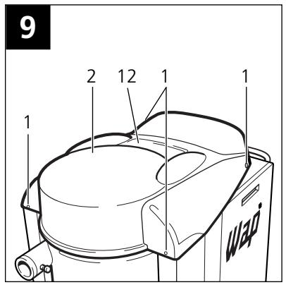
3.4.2 Changing filter element
(Fig. 9)
Pull mains plug.
- Unlock four quick-lock screws
(1) of cover (2) by turning 90^ and pull off.
- Lift off cover (2) and thread out power cable.
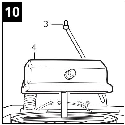
(Fig. 10)
- Disconnect connection hose of filter blow-off (3).
- Lift off cover (4) upward and lay toward rear on vacuum cleaner.
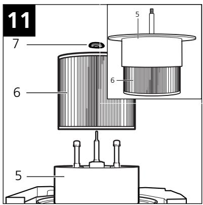
(Fig.11)
Pull out filter carrier ring (5) with filter element (6).
(Fig. 11)
- Lay filter carrier ring (5) upside down on vacuum cleaner.
- Screw off hand screw (7).
Pull off filter element (6) upward.
- Dispose of used filter element in accordance with legal regulations. Part No. for filter element: 34931.
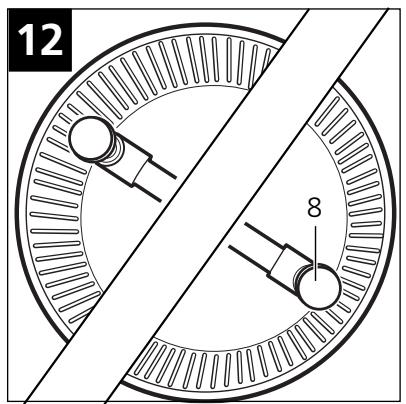
(Fig. 12)
- Insert new filter element centred.
Make sure filter blow-off (8) turns freely. - Fit hand screw and tighten.
(Fig. 11)
- Remount filter carrier ring (5) with filter element (6).
(Fig. 10)
- Fit cover (4), making sure that notches in cover are located over supports (9) of filter carrier ring.
- Screw on connection hose of filter blow-off (3) and tighten.
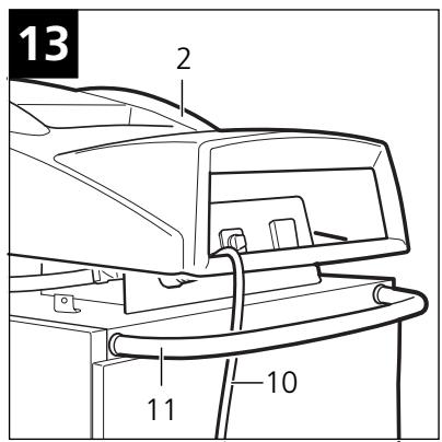
(Fig. 13)
- Fit cover (2).
- Guide power cable (10) through opening of cover (2) and under handle (11).
(Fig. 9)
- Move cover (2) into position. No lines may be visible in area of exhaust air outlet (12).
- Lock cover by pressing in four quick-lock screws (1).
3.5 Fault displays
3.5.1 Flashing fault lamp
If the rotating field of the power supply cord is incorrectly connected, the circuit breaker prevents the vacuum cleaner from being switched on.
- Switch off vacuum cleaner and pull mains plug.
- Have connection outlet connected according to standard (clockwise rotating field) by electrician.
3.5.2 Continuously lit fault lamp
Overcurrent fuse and/or temperature monitoring unit for turbine exhaust air has/have been triggered.
- Leave vacuum cleaner switched on and wait until fault lamp goes out, then switch off.
Make sure exhaust air outlet and cooling air inlet of motors are not blocked and clear if necessary. - Switch on vacuum cleaner again.
3.5.3 Acoustic filter warning
The filter element is extremely dirty.
- Clean filter element (see Section 3.4.1) or replace (see Section 3.4.2).
3.6 Checking exhaust-air flap
Exhaust-air flap of stopped turbine is jammed.
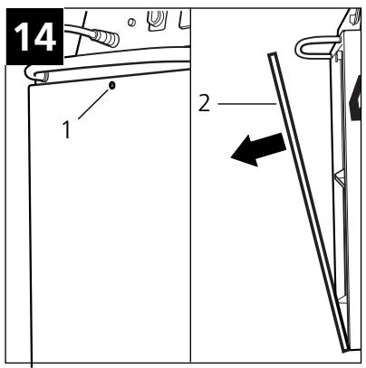
(Fig. 14)
- Release quick-lock screw (1) of vacuum-cleaner rear panel by turning 90^ .
- Tilt back vacuum-cleaner rear panel (2) and unhook.
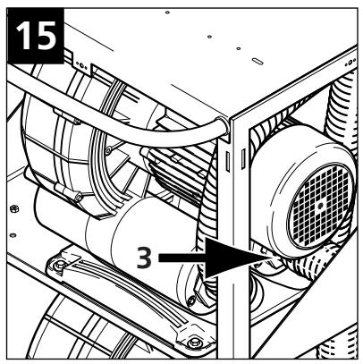
(Fig. 15)
- Check exhaust-air flap (3) of stopped turbine.
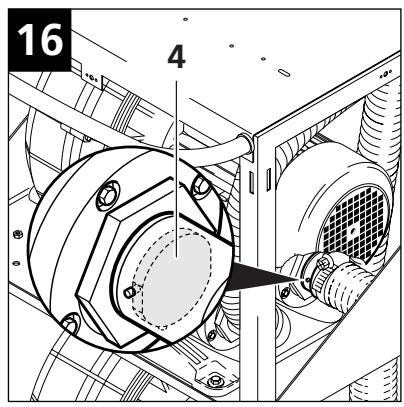
(Fig. 16)
- Bond paper piece onto bolt (4) of exhaust-air flap.
- Switch vacuum cleaner to position "I", then to position "II". Flap must move.
- If exhaust-air flap does not move, switch off vacuum cleaner and free up exhaust-air flap.
- Check for smooth movement by switching vacuum cleaner to position "I" first, and then to position "II". If exhaust-air flap still does not move, switch off vacuum cleaner and inform Wap Customer Service.

(Fig. 14)
- Hook in vacuum-cleaner rear panel (2) and tilt forward.
- Lock vacuum-cleaner rear panel by pressing in quick-lock screw (1).
3.7 Trouble-shooting
Fault
Motor does not run
Cause
Mains plug not plugged in
Circuit breaker of connection outlet has been tripped
Circuit breaker tripped due to wrong rotating field
Overcurrent protection or temperature monitoring unit has been triggeredAutomatic mode only:
- No vacuum power is required
- Contact loop of automatic system not closed
Remedy
Plug mains plug into outlet, see Section 2.3
- Reset circuit breaker
See Section 3.5.1
See section 3.5.2. If overcurrent protection or temperature monitoring unit triggers repeatedly, inform Wap Customer Service
- Check contact loop(s) or contact points
Reduced suction power
Suction nozzle blocked
Suction hose blocked
Filter cartridge dirty
- Clean suction nozzle
- Clean suction hose
- Clean filter cartridge (see Section 3.4.1) or replace (see Section 3.4.2)
See Section 3.6
4 Wap Service
4.1 Warranty
Our General Conditions of Sale and Delivery apply for the warranty and warranty period.
4.2 Company address
Wap
EU Declaration of Conformity
The design of the unit corresponds to the following pertinent regulations:
EC Machine Directive
EC Low-voltage Directive
EC EMV Directive
89/392/EWG 73/23/EWG 89/336/EWG
Applied harmonised standards:
Applied national standards and technical specifications:

ppa. Rau, Dipl. Ing. (FH)
Head of Research and Development
DIN VDE 0700 T 205
Bellenberg, 03.02.1997

24 Constellation Road
Rexdale
Ontario M9W 1K1
Canada
Division of Nilfisk-Advance A/S
Industrivej 1
9560 Hadsund
Denmark
Tel.: (+45) 72 18 21 00
Fax: (+45) 72 18 21 11
Nilfisk-ALTO Food Division
Division of Nilfisk-Advance A/S
Blytaekkervej 2,
9000 Aalborg
Denmark
Tel.: (+45) 72 18 21 00
Fax: (+45) 72 18 20 99
E-mail: scanio.techology@nilfisk-alto.dk
www.nilfisk-alto.com
FRANCE
Nilfisk-ALTO
ALTO France SA
Aéroparc 1
19 rue lcare
67960 Entzheim
France
Tel.: (+33) 388288400
Fax: (+33) 388300500
E-mail: info@nilfisk-alto-fr
www.nilfisk-alto.com
GERMANY
Nilfisk-Advance AG
Nilfisk-ALTO Business Unit
Division of Nilfisk-Advance BV
Camastraat 9
NL-1322 BB Almere
Tel.: (+31) 36 5460 760
Fax: (+31) 36 5460 761
E-mail: info@nilfisk-alto.nl
www.nilfisk-alto.nl
HONG KONG
Nilfisk-Advance Ltd.
2001 HK Worsted Mills Ind'l Bldg.,
31-39 Wo Tong Tsui St.
Kwai Chung, Hong Kong
Tel.: (+852) 2427 5951
Fax: (+852) 2487 5828
HUNGARY
Kvantor-Itb Kft
Leisure Commerce Square
No. 9, Jalan PJS 8/9
46150 Petaling Jaya
Selangor, Malaysia
Tel.: (+60) 360378764222
Fax: (+60) 3 603 7876 3878
PEOPLE'S REPUBLIC OF CHINA
Nilfisk-Advance (Shenzhen) Ltd
Blok 3, Unit 130, 1001 Honghua Road
Int. Commercial & Trade Center
Fuitian Free Trade Zone
518038 Shenzhen
P.R.China
Tel.: (+86) 755 8359 7937
Fax: (+86) 755 8359 1063
POLAND
Nilfisk-ALTO
Division of Nilfisk-Advance A/S
05-800 Pruszków
ul. 3-go MAJA 8
Poland
Tel.: (+48) 227383750
Fax: (+48) 22 738 37 51
info@nilfisk-alto.pl
www.nilfisk-alto.pl
NORWAY
ALTO Norge AS
Bjornerudveien 24
1266 Oslo
Norway
Tel.: (+47) 22 75 17 70
Fax: (+47) 22 75 17 71
Sintra Business Park
Zona Industrial Da Abrunheira
Edificio 1, 1^ A
P-2710-089 Sintra
Tel.: (+35) 808 200 537
Fax: (+35) 121 911 2679
E-mail: mkt@nilfisk-advance.es
www.nilfisk-alto.com
SINGAPORE
Nilfisk-Advance Pte. Ltd.
Nilfisk-ALTO Division
40 Loyang Drive
Singapore 508961
sales@nilfisk-advance.com.sg
Member of Nilfisk-Advance Group
Aminogatan 18, Box 4029
S-431 04 Molndal
Sweden
Tel.: (+46) 317067300
Fax: (+46) 31 706 73 40
E-mail: info@nilfisk-alto.se
www.nilfisk-alto.se
TAIWAN
Nilfisk-Advance Ltd.
Taiwan Branch (H.K.)
1F. No. 193. Sec.2
Xing Long Rd., Taipei
Taiwan, R.O.C.
Tel.: (+886) 2 2239 8812
Fax: (+886) 2 2239 8832
THAILAND
Nilfisk-Advance Co. Ltd.
89 Soi Chokechai-Ruammitr
Viphavadee-Rangsit Road
Ladyao, Jatuchak, Bangkok 10900
Thailand
Tel.: (+66) 2 275 5630
Fax: (+66) 2 691 4079
UNITED KINGDOM
Nilfisk-ALTO
Division of Nilfisk-Advance Ltd.
Bowerbank Way
Gilwilly Industrial Estate
Penrith Cumbria CA11 9BQ
Great Britain
Tel.: (+44) (0) 1768 868995
Fax: (+44) (0) 1768 864713
E-mail: sales@nilfisk-alto.co.uk
www.nilfisk-alto.co.uk
USA
ALTO Cleaning Systems Inc.
Part of the Nilfisk-Advance Group
12249 Nations Ford Road
Pineville, NC 28134
USA
- GENERAL
- HEALTH-ENDANGERING DUSTS*)
- FIRE AND EXPLOSION HAZARD
- APPLIANCE PLUG SOCKET
- CAUTION!
- USING FOR THE FIRST TIME
- (Damaged mains leads present a danger of electric shocks!)
- DURING OPERATION
- MAINTENANCE AND REPAIR
- ELECTRICAL EQUIPMENT
- Description
- Illustration
- (Fig. 1)
- Application
- Inspections and approvals
- Technical data
- Dynamics 840
- Accessories, additional equipment
- Use/Operation
- Setting up vacuum cleaner
- (Fig. 2)
- Connecting suction hose
- (Fig. 3)
- Electrical connection
- Vacuuming
- Operating vacuum cleaner
- Before switching on
- (Fig. 4)
- Switching vacuum cleaner on/off
- NOTE!
- Following work
- Care/Maintenance
- Important safety precautions
- Maintenance schedule
- Emptying tank
- (Fig. 6)
- (Fig. 7)
- Filter element
- Blowing off filter
- (Fig. 8)
- Changing filter element
- (Fig. 9)
- (Fig. 10)
- (Fig.11)
- (Fig. 11)
- (Fig. 12)
- (Fig. 13)
- Fault displays
- Flashing fault lamp
- Continuously lit fault lamp
- Acoustic filter warning
- Checking exhaust-air flap
- (Fig. 14)
- (Fig. 15)
- (Fig. 16)
- Trouble-shooting
- Fault
- Cause
- Remedy
- Wap Service
- Warranty
- Company address
- EU Declaration of Conformity
- FRANCE
- GERMANY
- HONG KONG
- HUNGARY
- PEOPLE'S REPUBLIC OF CHINA
- POLAND
- NORWAY
- SINGAPORE
- TAIWAN
- THAILAND
- UNITED KINGDOM
- USA
Brand : NILFISK
Model : DYNAMICS 840
Category : Industrial vacuum cleaner