
GFX4 - Guitar Effects ZOOM - Free user manual and instructions
Find the device manual for free GFX4 ZOOM in PDF.
| Product type | Guitar effects processor |
| Brand | ZOOM |
| Model | GFX-4 |
| Dimensions | 397 mm (W) x 183 mm (D) x 60 mm (H) |
| Weight | 1.4 kg |
| Power supply | Included AC adapter (ZOOM only) |
| Number of patches | 120 (60 user + 60 presets) |
| Number of effects modules | 6 + ZNR + amp simulator |
| Effect types | 44 effects + ZNR + amp simulator |
| Sampling frequency | 40 kHz |
| A/D conversion | 20-bit, 64x oversampling |
| D/A conversion | 20-bit, 128x oversampling |
| Input | Mono jack (instrument) |
| Outputs | Mono jack output + stereo jack output |
| Main functions | Patch selection and editing, expression pedal, chromatic tuner, bypass/mute, RTM, amp and cabinet simulation |
| Maintenance and cleaning | Soft dry cloth; avoid abrasive products, solvents or alcohol |
| Safety | Use only the included adapter; avoid extreme temperatures, humidity, dust, shocks; do not open the casing |
| Spare parts and repairability | Contact an authorized ZOOM distributor; no user-serviceable parts |
| General information | Warranty: refer to the provided document; manufactured by ZOOM Corporation, Japan |
Frequently Asked Questions - GFX4 ZOOM
User questions about GFX4 ZOOM
0 question about this device. Answer the ones you know or ask your own.
Ask a new question about this device
Download the instructions for your Guitar Effects in PDF format for free! Find your manual GFX4 - ZOOM and take your electronic device back in hand. On this page are published all the documents necessary for the use of your device. GFX4 by ZOOM.
USER MANUAL GFX4 ZOOM
Safety Precautions/Usage Precautions 2
Introduction 3
Terms Used in This Manual 4
Controls and Functions 5
Top Panel 5
Rear Panel 5
Getting Connected 6
Guitar amp/instrument connection 6
About the Mono Output 6
Preparations 7
Power Up 7
Using the Amp Simulator 7
Operation Guide 1 Selecting Patches for Playing 8
(1) Turn on the power
(2) Select the patch
(3) Select the bank.
(3) Select the bank. (4) Open it.
(4) Select the group
(5) Use the pedal
Operation Guide 2 Editing Patches 10
(1) Select module to edit
(2) Switch effect modules on and off
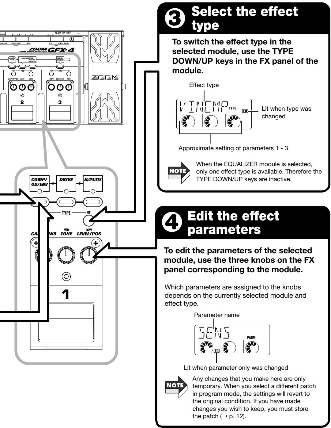
(3) Select the effect type
(4) Edit the effect parameters
Operation Guide 3 Storing/Swapping Patches 12
(1) Switch the GFX-4 to store mode
(2) Select the store target patch
(3) Select whether to store or swap the patch
(4) Carry out the store/swap process
Operation Guide 4 Using the Tuner (Bypass/Mute) Function 14
(1) Set the GFX-4 to bypass(mute)
(2) Tune your guitar
(3) Adjust the reference pitch of the tuner
(4) Return to program mode
Editing Operations 16
Operation Differences of Manual Mode and Program Mode 17
Setting the Patch Level and Patch Name 18
Setting the ZNR Threshold 18
Using the Expression Pedal (RTM function) 19
PEDAL WAH/PEDAL PITCH Key 20
Effect Types and Parameters 21
About module and Effect Types 21
COMP/OD/ENV module 21
DRIVE module 22
EQUALIZER module 23
PEDAL module 23
MODULATION module 24
DELAY/REVERB module 26
Other Functions 28
All Initialize 28
Adjusting the Expression Pedal 28
Troubleshooting 29
Specifications 29
Patch List 30
Creating Your Own Sound 31
Safety Precautions/Usage Precautions
Safety Precautions
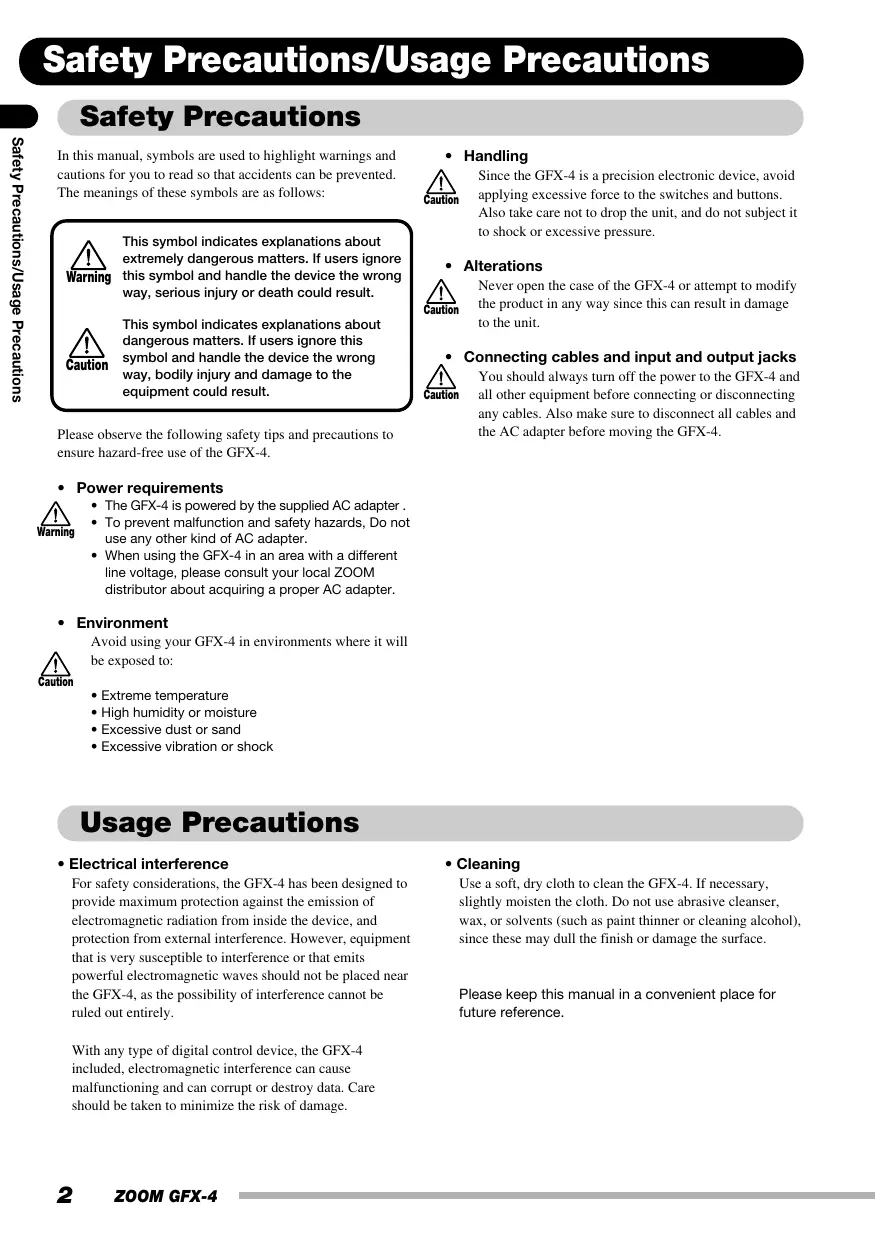
In this manual, symbols are used to highlight warnings and cautions for you to read so that accidents can be prevented. The meanings of these symbols are as follows:

This symbol indicates explanations about extremely dangerous matters. If users ignore this symbol and handle the device the wrong way, serious injury or death could result.

This symbol indicates explanations about dangerous matters. If users ignore this symbol and handle the device the wrong way, bodily injury and damage to the equipment could result.
Please observe the following safety tips and precautions to ensure hazard-free use of the GFX-4.
Power requirements

- The GFX-4 is powered by the supplied AC adapter.
- To prevent malfunction and safety hazards, Do not use any other kind of AC adapter.
- When using the GFX-4 in an area with a different line voltage, please consult your local ZOOM distributor about acquiring a proper AC adapter.
Environment

Avoid using your GFX-4 in environments where it will be exposed to:
Extreme temperature
High humidity or moisture
- Excessive dust or sand
- Excessive vibration or shock
Handling

Since the GFX-4 is a precision electronic device, avoid applying excessive force to the switches and buttons. Also take care not to drop the unit, and do not subject it to shock or excessive pressure.
- Alterations

Never open the case of the GFX-4 or attempt to modify the product in any way since this can result in damage to the unit.

Connecting cables and input and output jacks You should always turn off the power to the GFX-4 and all other equipment before connecting or disconnecting any cables. Also make sure to disconnect all cables and the AC adapter before moving the GFX-4.
Usage Precautions
- Electrical interference
For safety considerations, the GFX-4 has been designed to provide maximum protection against the emission of electromagnetic radiation from inside the device, and protection from external interference. However, equipment that is very susceptible to interference or that emits powerful electromagnetic waves should not be placed near the GFX-4, as the possibility of interference cannot be ruled out entirely.
With any type of digital control device, the GFX-4 included, electromagnetic interference can cause malfunctioning and can corrupt or destroy data. Care should be taken to minimize the risk of damage.
- Cleaning
Use a soft, dry cloth to clean the GFX-4. If necessary, slightly moisten the cloth. Do not use abrasive cleanser, wax, or solvents (such as paint thinner or cleaning alcohol), since these may dull the finish or damage the surface.
Please keep this manual in a convenient place for future reference.
Thank you for selecting the ZOOM GFX-4 (simply called the "GFX-4" in this manual). The GFX-4 is a sophisticated Guitar Effects Processor with the following features.
- Versatile array of effects
The Variable Architecture Modeling System (VAMS) adapts the internal configuration of the unit to achieve exactly the desired sound. The GFX-4 includes vintage effects such as famous overdrive, distortion, compressor, and phaser sounds of the seventies and eighties, as well as ultra-modern processing functions. Up to eight effects can be freely combined for simultaneous use.
Great choice of distortion sounds
In addition to traditional guitar amplifier characteristics, the GFX-4 uses modeling technology to duplicate the sound and operation feel of celebrated compact distortion effects. Well-proven combinations such as booster + distortion or compressor + overdrive can be established quickly and easily. By combining distortion effects with the built-in amp and cabinet simulator, you can get optimum sound also for line out recording.
Designed to get the best out of any guitar
The ACTIVE NORMAL switch provides quick and precise impedance and level matching for any guitar. Whether you have a passive pickup or use an active pickup or integrated preamp, your instrument will sound its best.
The OUTPUT MONO jack uses analog bypass with a mechanical switch, so that the output in bypass mode is not subject to any kind of digital signal processing.
Simple and intuitive operation
Thanks to three FX panels, the GFX-4 can be operated like a series of compact effects. Foot switches are convenient for turning effects on and off, and sound parameters can be adjusted quickly with rotary controls. The Easy Edit function is a snap to use also during a performance. With the GFX-4, playing your instrument and editing the sound is one seamless operation.
Extensive patch library
A combination of effects can be assigned a name of up to six characters and stored as a patch in the memory of the unit. There are 60 user patches (4 groups x 5 banks x 3 patches) which can be freely rewritten, plus 60 preset patches that make the unit ready to use right out of the box. The possibilities are almost endless.
Great for use on stage
The GFX-4 incorporates an expression pedal that can serve as real-time effect controller or volume pedal. The easy-to-read 6-character display and 2-character indicator make it easy to check patch names and settings at a glance, which is helpful during a live gig.
In order to get the most out of this sophisticated product, please read this manual carefully before use.
We recommend that you keep the manual at hand for future reference.
Terms Used in This Manual
This section explains some important terms that are used throughout the GFX-4 documentation.
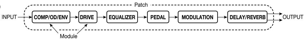
Module
A "module" is a section that works like a stand-alone compact effect device for tailoring certain aspects of the sound. In the GFX-4, you can use the six modules
COMP/OD/ENV, DRIVE, EQUALIZER, PEDAL, MODULATION, and DELAY/REVERB as well as the ZNR (Zoom Noise Reduction) + AMP SIM (Amp Simulator) simultaneously.
Effect types and parameters
Within each effect module, there are various effect types which are specific processing functions. The various settings of the currently selected effect type are called parameters. By selecting an effect type and varying the parameters, you can create a new effect.
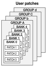
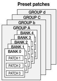
Patch/group/bank
Effect module combinations and effect parameter settings are stored in memory as "patches". The GFX-4 can hold a total of 120 patches. These are divided into 60 user patches which are read/write, and 60 read-only preset patches. Both the user patches and preset patches are divided into four groups (A, b, C, d). Each group has 5 banks numbered from 0 - 4, and each bank has 3 patches. To use a patch in the GFX-4, you first call up the bank and then use the three foot switches 1 - 3 to select the patch.
Modes
Operation of the GFX-4 is divided into five main modes, as listed below.
Program mode
This is the basic operation mode of the GFX-4. The unit is always in this mode after power is turned on.
The mode is used for switching patches and for editing the currently selected patch.
- Manual mode
This mode lets you switch modules on and off, operating the unit in the same way as a compact effect with the knobs and foot switches on the FX panels.
- Store mode
This mode serves for storing patches edited in program mode or manual mode in the memory of the unit. It also allows changing the store positions of user patches.
- Bypass/mute mode
When the GFX-4 is in the bypass condition, effect processing is temporarily turned off and only the original sound is heard. In the mute mode, all sound is turned off and the built-in chromatic tuner can be used.
Special mode
This mode serves for making amp simulator and ZNR settings, patch name and patch level settings, and for returning the GFX-4 to the factory default condition.
RTM (real-time modulation)
The RTM function allows use of the expression pedal to adjust DRIVE, MODULATION, or DELAY/REVERB module parameters or the volume in real time. For example, you might use the pedal during a performance to vary the reverb mix balance or adjust wah intensity with your foot. The module, effect type, and parameter, as well as the parameter change direction can be set separately for each patch.
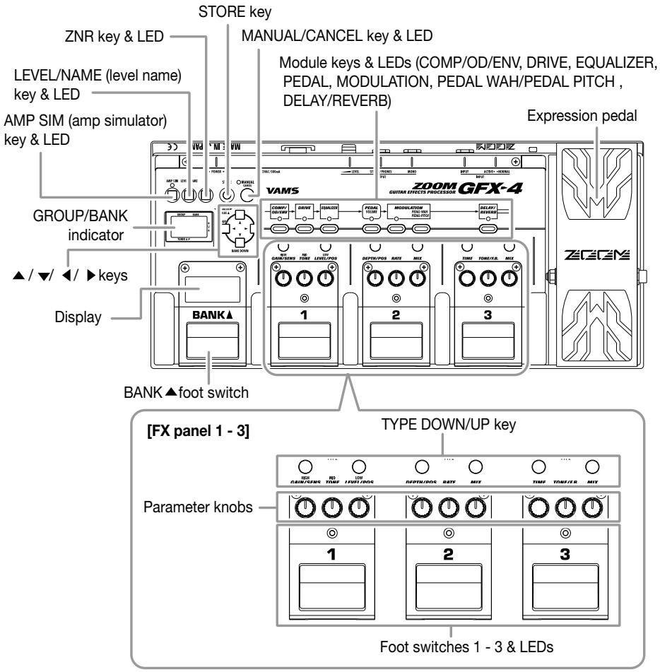
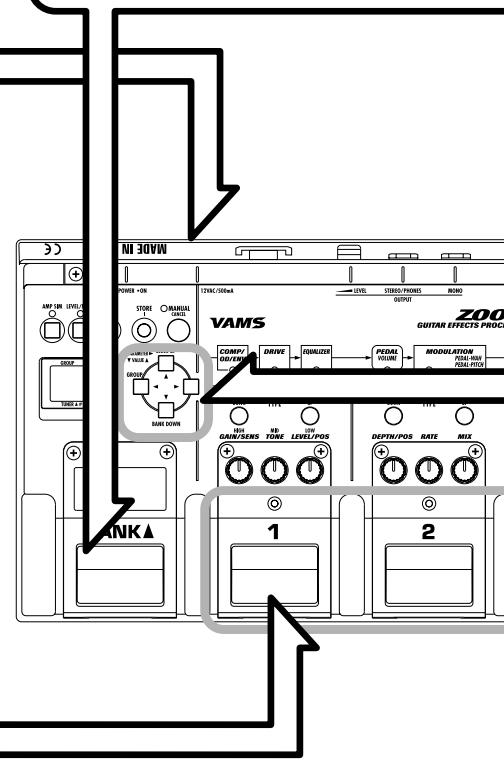
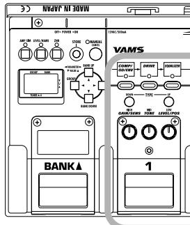
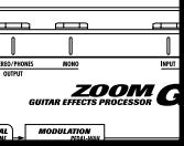
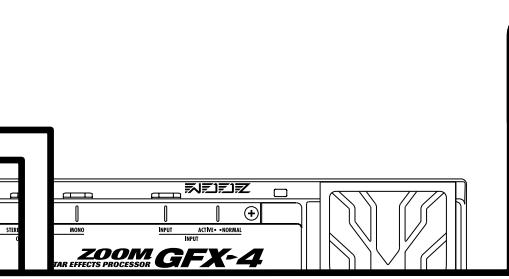
Controls and Functions
Top Panel
Rear Panel
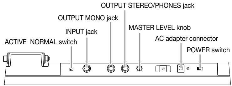
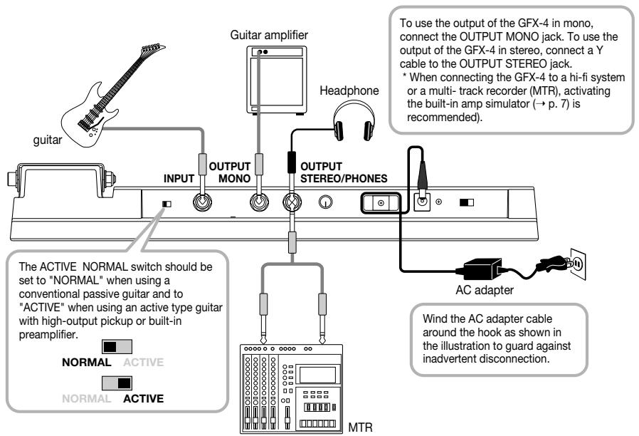
Guitar amp/instrument connection
About the Mono Output
The GFX-4 has two output jacks labeled OUTPUT STEREO and OUTPUT MONO. When the OUTPUT MONO jack is used, a mechanical relay switch operates in bypass mode, which results in true bypass (analog bypass where the signal is not subject to any kind of digital processing).
When using effects
The OUTPUT MONO jack supplies only the left-channel signal. This is suitable for example for connection to a guitar amp or another effect device.
When using Bypass
When the GFX-4 is in bypass mode, the analog input signal appears unchanged at this jack, due to the action of a switching relay. (This means that there is absolutely no sound quality change caused by digital processing.) Note that the expression/volume pedal and the MASTER LEVEL knob have no effect on the signal in this condition.
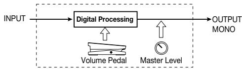
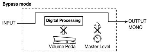

When wishing to use the volume pedal and master level control also in bypass mode, use the OUTPUT STEREO jack.
Power Up
- Verify that the AC adapter, instrument, and amplifier are correctly connected to the GFX-4.
-
Turn the system on in the order GFX-4 amplifier.
-
While playing your instrument, adjust the volume control on the amplifier, the level control of the instrument, and the MASTER LEVEL knob of the GFX-4 to a suitable position.
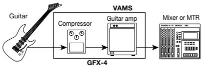
Using the Amp Simulator
When the GFX-4 is connected to a hi-fi system or multi-track recorder (MTR), set up the amp simulator to match your preferences.
- Immediately after turning on the GFX-4, press the AMP SIM key.

The AMP SIM key LED lights up, showing that amp simulator setup is possible.
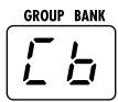
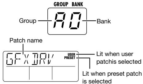
- Use the / keys to call up the indication "AMPTYP" on the display, and use the / keys to select the amp simulator type.

The following AMPTYP settings are available.
oF: Amp simulator is turned off. (CABTYP and CABDPT parameters are also inactive.)
Cb: Conventional combo amp simulation
bC: Bright combo amp simulation
St: Stack amp simulation
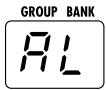
The current setting can be checked on the GROUP/BANK indicator.
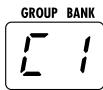
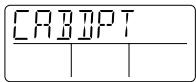
- Use the / keys to call up the indication "CABI" on the display, and use the / keys to select the cabinet simulator type.
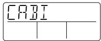
The following CABTYP settings are available.
oF: Cabinet simulator is turned off. (CABDPT parameter is also inactive.)
C1: Combo amp cabinet (12" speaker x 1)
C2: Combo amp cabinet (12" speaker x 2)
St: Stack amp cabinet (10" speaker x 4)
WL: Simulates the sound of a stacked array of St type cabinets.
- Use the / keys to call up the indication "CABDPT" on the display, and use the / keys to adjust the intensity of the cabinet simulator effect.
The setting range is 0 - 10. Higher values result in stronger cabinet sound.
GROUP BANK
- When the setting is complete, press the STORE key two times.
The amp simulator setting is stored. This setting applies to all patches.
Operation Guide 1 Selecting Patches for Playing
In the factory default condition, the memory of the GFX-4 contains 60 rewrites per user patches and 60 read-only preset patches. This section shows you how to select patches while playing your instrument. Try it out for yourself, to see what the GFX-4 can do.
1 Turn on the power
Turn power on in the order GFX-4 amp/playback system.
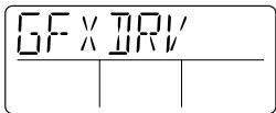
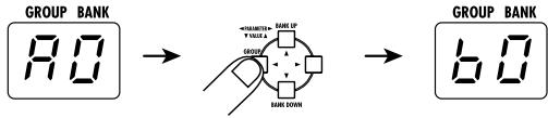
The GFX-4 automatically goes into program mode. In this mode, the display and the GROUP/BANK indicator show the following information.
3 Select the bank
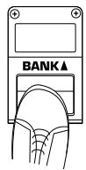
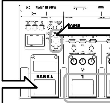
To choose a patch from a different bank, use the BANK foot switch to select the bank and then use foot switches 1 - 3 to select the patch.
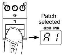
2 Select the patch
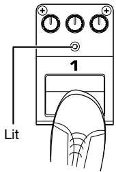
To switch patches within the same bank, simply press one of the foot switches 1 - 3 whose LED is not currently lit.
In program mode, foot switches 1 - 3 serve for patch switching.
The LED of the foot switch corresponding to the current patch is lit.

When the GFX-4 is in manual mode
(MANUAL key LED lit), foot switches 1 - 3
turn the various modules on and off.
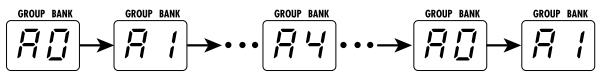
For example, when group A is currently selected, the BANK foot switch will move through the banks as follows: A0 A1 A2 A3 A4 A0 etc.
The actual patch is switched after you press one of the foot switches 1 - 3.

Select the group
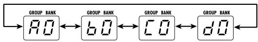
To switch to a different group, use the / keys or the / keys.
Each push of the / keys switches groups in the order user patches A b C d followed by preset patches A b C d .
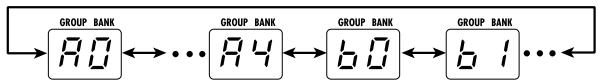
Each push of the / keys switches banks and groups in the order A0 A1 A2 A3 A4 b0 b1 etc.
(Switching between user patches and preset patches is not carried out.)
Use the pedal
The built-in expression pedal of the GFX-4 lets you adjust the volume or effect parameters in real time. Move the pedal while playing your instrument to try out some of the possibilities.

In either case, the actual patch is switched only after you press one of the foot switches 1 - 3.
Operation Guide 2 Editing Patches
The GFX-4 allows you to edit patches both in program mode and manual mode.
In program mode, the display will revert to its original condition about 5 seconds after the last editing operation was performed. In manual mode, the display remains unchanged after the last editing operation.
In manual mode, the foot switches 1 - 3 can be used to switch effects on and off.
To activate manual mode, press the MANUAL key in program mode.

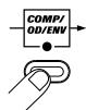
Select module to edit
Use the module keys to select the module that you want to edit.
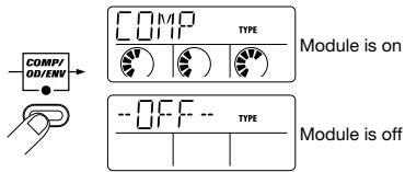
The LED of the selected module flashes in red. The display shows the following information.
When module is on
When module is off

When a module is set to off, it cannot be edited. Turn the module on first.

Switch effect modules on and off
To toggle the selected module between on and off, press the FX panel key corresponding to that module.
In manual mode, module on/off switching can also be performed with foot switches 1 - 3.
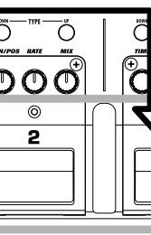
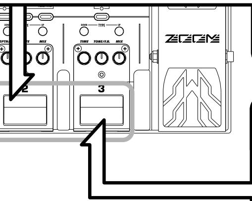
The modules are assigned to FX panels 1 - 3 as shown at right.
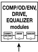
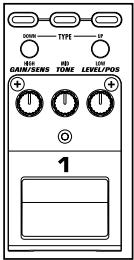
FX panel 1
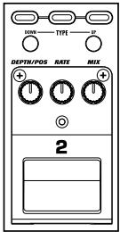
FX panel 2
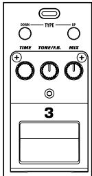
FX panel 3
Operation Guide 3 Storing/Swapping Patches
Unless you store an edited patch in the memory of the unit, the changes you have made will be lost when you select another patch. Don't forget to store the patch when you want to keep your changes.
Switch the GFX-4 to store mode
In program mode or manual mode, press the STORE key.
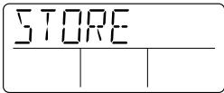
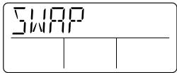
The name of the currently selected patch and the indication "STORE" or "SWAP" are shown alternately on the display. The GROUP/BANK indicator shows the group/bank that will be used as a target for storing or swapping.

GROUP BANK

GROUP BANK


Store
Swap

Preset patches are read-only and cannot be overwritten. If the store mode is activated while a preset patch is selected, the user patch with the same group/bank/patch number is automatically selected as store target.
When "SWAP" is selected, data are changed as follows.
Store target patch data original patch number
Currently selected patch data Store target patch number
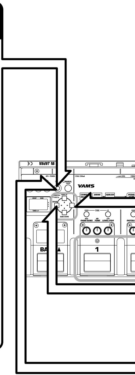
2 Select the store target patch
Use the / / / keys, and foot switches 1 - 3 to select the group, bank, and patch number that is to be used as a store target.

It is also possible to use the BANK foot switch to select the store target bank.

Select whether to store or swap the patch
Use the key.
Each push of the key toggles between the "STORE" and "SWAP" setting. Select the desired action.

If the original patch was a preset patch, the "SWAP" setting is not available.
4 Carry out the store/swap process
Press the STORE key once more.
The store/swap process is carried out and the unit reverts to the same condition as before the store mode was activated. When wishing to cancel the process, press the MANUAL/CANCEL key instead.
Operation Guide 4 Using the Tuner (Bypass/Mute) Function
The GFX-4 has a built-in auto-chromatic tuner for guitars. To use the tuner function, the built-in effects must be bypassed (temporarily turned off) or the unit must be muted (original sound and effect sound turned off).
1 Set the GFX-4 to bypass (mute)
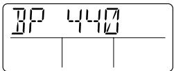
When the GFX-4 is in program mode, press and release the foot switch of the currently selected patch (the switch whose LED is lit).
Pressing and immediately releasing the foot switch sets the unit to the bypass condition, and the indication "BP 440" is shown on the display.
When GFX-4 is in manual mode, press and immediately release BANK switch.
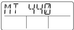
Pressing and holding the foot switch for more than 1 second sets the unit to the mute condition, and the indication "MT 440" is shown on the display.
When GFX-4 is in manual mode, press BANK switch for about 1 second.

While the GFX-4 is in bypass mode, the expression pedal cannot be used as a volume pedal for the guitar OUTPUT MONO jack.
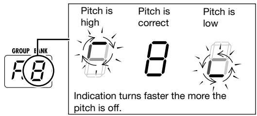
Tune your guitar
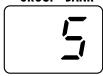
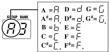
Play the open string you want to tune, and watch the GROUP/BANK indicator.
The GFX-4 automatically detects the pitch and the indicator shows the note which is closest to the current pitch.

For tuning, always play a single note. If you play a chord, the pitch will not be detected correctly.

Adjust the reference pitch of the tuner
Use the / keys.
After the GFX-4 is turned on, the tuner reference pitch is always "440" (center A = 440 Hz). If desired, you can change the reference pitch in 1 Hz steps over the range from "435" (center A = 435 Hz) to "445" (center A = 445 Hz).
NOTE
The reference pitch is reset to "440" when the unit is turned off and on again.

Return to program mode
When tuning is completed, press any foot switch.
The GFX-4 returns to the program mode.
When the GROUP/BANK indicator shows the desired note, perform fine tuning while watching the display.
Editing Operations
This section describes the various editing operations that can be carried out with the unit.
The basic steps for patch editing are as follows.
1. While the GFX-4 is in program mode, select the patch you want to edit.
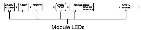
The module LEDs show the status of each module within that patch.
COMP/OD/ENV, DRIVE, EQUALIZER module LEDs
COMP/OD/ENV, DRIVE, and EQUALIZER share the FX pedal 1 which can be assigned to any of these modules. However, when the assigned module is off (module LED lit in green), operating the FX pedal 1 only switches module on or off.
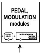
MODULATION, DELAY/REVERB module LEDs
| MODULATION PEDAL-WAY PEDAL-PITCH | DELAY/ REVERSE |
| Module LED status | Module on/off status |
| Lit red | On |
| Out | Off |

- The MODULATION and PEDAL modules share the FX pedal 2. Normally, the FX pedal 2 controls the MODULATION module, but when the PEDAL module is selected as operation target, the FX pedal 2 controls the PEDAL module. The PEDAL module LED is flashing.
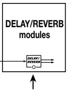
- The FX pedal 3 is permanently assigned to the DELAY/REVERB module. It always controls the DELAY/REVERB module.
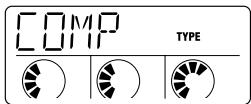
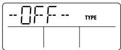
2. Press one of the module keys (COMP/OD/ENV, DRIVE, EQUALIZER, PEDAL, MODULATION, DELAY/REVERB) to select the target module.
The LED of the selected module flashes, and the display shows the name of the effect type selected for that module (if the module is on), or "-OFF--" (if the module is off).
3. To toggle the selected module between on and off, press the module key of the corresponding FX panel again.

You can also switch between on and off by pressing the module key of the module whose LED is flashing.

The PEDAL module serves for making expression pedal settings. It is not a regular effect and can therefore not be turned off.
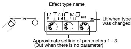
4. To switch the effect type of the selected module, use the TYPE DOWN/UP keys on the corresponding FX panel.
For example, when switching a module from on to off, the module LED changes from flashing red to flashing green.
The assignment of FX panels 1 - 3 to the modules is as follows.
- FX panel 1: COMP/OD/ENV, DRIVE, EQUALIZER module
- FX panel 2: PEDAL, MODULATION module
- FX panel 3: DELAY/REVERB module
The name of the currently selected effect type is shown on the display.
- Unlike other modules, the EQUALIZER module has only one effect type. Therefore pressing the TYPE DOWN/UP keys has no effect. (The display shows only EQUALIZER "HIGH".)
- When a module that is currently set to off is selected, the effect type and parameter cannot be changed.

For the effect types PDLWAH (pedal wah) and PDLPIIT (pedal pitch) in the MODULATION module only, it is possible to directly call up the editing display by pressing the PEDAL WAH/PEDAL PITCH key. For details, see page 26.
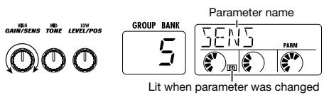
5. To set the effect parameters of the selected module, operate parameter knobs 1 - 3 of the corresponding FX panel.
The display shows the most recently edited parameter name, and the GROUP/BANK indicator shows the value of the parameter.

You can also use the / keys and / keys to select the effect type and alter the parameter value. The / keys serve to bring up the effect type or parameter 1 - 3, and the / keys serve to adjust the value.
- Use the module keys to select another module and adjust the effect type/parameter value and on/off setting in the same way.
- When editing is completed, store the patch as required.

If you call up another patch in program mode without storing the current patch, any editing changes will be lost.
Operation Differences of Manual Mode and Program Mode
When the MANUAL key is pressed while the GFX-4 is in program mode, the unit switches to manual mode. (Pressing the key again switches back to program mode.)
In manual mode, the foot switches 1 - 3 on the FX panels serve to turn modules on and off. This lets you change the sound of the currently selected patch in a way similar to using a compact effect.
Operation differences in manual mode and program mode are listed below.
| Manual mode | Program mode | |
| Module LED DisplayGROUP/BANKindicator | Module LED of last edited module flashes and display shows parameter name/effect type name. GROUP/BANK indicator shows parameter value. | Module LED indication of last edited module, display and GROUP/BANK indicator function are the same as in program mode, but display reverts to program mode initial display after about 5 seconds. |
| Foot switches1 - 3 | Switch respective module on and off | Switch patches |
| To activate bypass (mute) mode | Press BANK ▲ switch | Press foot switch of currently selected patch number (LED lit) |
Setting the Patch Level and Patch Name
When a patch has been completed, you can give it a name of up to six characters, and adjust the patch level (the final output level for each patch).
- In manual mode or program mode, press the LEVEL/NAME key.
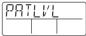
- Use the / keys to bring up the indication "PATLVL" on the display.
This display allows setting the final patch level in the range from 1 - 50. (A patch level setting of 40 means that the input level and output level are equal.) The current setting is shown on the GROUP/BANK indicator.

- Use the / keys to adjust the patch level.
- Use the keys to bring up the patch name on the display.
This display allows changing the patch name. The flashing character is the one that is currently selected for editing.
- Use the / keys to select the character to be edited, and change the character with the / keys. The following alphanumeric characters and symbols are available.
| Space | / | ( ) | ¥ | + | - | / | 0 | 1 | 己 | 乙 | |
| Space | * | ( ) | * | + | - | / | 0 | 1 | 2 | 3 | |
| 4 | 5 | 6 | 7 | 8 | 9 | / | - | \ | A | B | |
| 4 | 5 | 6 | 7 | 8 | 9 | < | = | > | @ | A | B |
| [ ] | E | F | G | H | I | J | K | L | M | N | |
| C | D | E | F | G | H | I | J | K | L | M | N |
| O | P | Q | R | S | T | U | V | W | X | Y | Z |
| O | P | Q | R | S | T | U | V | W | X | Y | Z |
- When the patch level and patch name have been set, press the LEVEL/NAME key.
The GFX-4 returns to the previous mode. If required, store the patch ( p. 12 - 13).

If you call up another patch in program mode without storing the current patch, any editing changes will be lost.
Setting the ZNR Threshold
The GFX-4 incorporates the ZNR (ZOOM Noise Reduction) circuit which is highly effective in minimizing noise in playing pauses. You can set the ZNR threshold individually for each patch.
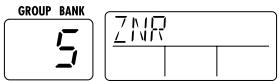
- In manual mode or program mode, press the ZNR key.
The indication "ZNR" appears on the display, and the current setting (oF, 1 - 10) is shown on the GROUP/BANK indicator.
- Use the / keys to adjust the ZNR threshold (sensitivity).
Choose the value which yields the best noise reduction without causing the sound to be cut off abruptly. The setting "oF" means that ZNR is turned off.
- When the threshold has been set, press the ZNR key once more.
The GFX-4 returns to the previous mode. If required, store the patch.

If you call up another patch in program mode without storing the current patch, any setting changes will be lost.
Using the Expression Pedal (RTM function)
The GFX-4 has an integrated expression pedal that can be used to adjust the volume or effect parameters in real time. This function is called RTM (Real Time Modulation). This section explains how to make RTM settings and use the function.
1. Select the patch for which you want to make RTM settings, and press the PEDAL module key in manual mode or program mode.
The PEDAL module display is shown. This module serves for making expression pedal settings.

The RTM setting can be made in manual mode or program mode. However, if the PEDAL module key is pressed in program mode, the unit reverts to the original condition if no control is operated for 5 seconds.
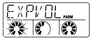
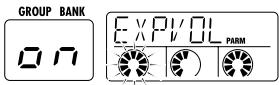
2. Use the pedal module key to bring up the indication "EXPVOL" on the display.

This display lets you make settings for using the expression pedal as a volume pedal and for selecting the function of the assignable switch built into the expression pedal.
3. Use knobs 1 - 3 of FX panel 2 to set the following parameters.
Parameter Knob 1 .... EXPVOL
Determines whether the expression pedal is used as a volume pedal in this patch. You can select "oF" (off) or "on".
Parameter Knob 2 MINVOL
When the "on" setting is selected with knob 1, you can set the minimum volume (the volume when the pedal is fully raised) with this knob. The setting range is 0 - 9.
Parameter Knob 3....EXP-SW
The expression pedal incorporates an assignable switch (electronic switch that is toggled between on and off when the pedal is fully depressed). This knob lets you select the function of the switch from the following two options.
0: Toggle RTM controlled module on/off status
1: Switch between program mode and manual mode
Depending on which knob is operated, the parameter name appears on the display and the current setting is shown on the GROUP/BANK indicator.

To use the expression pedal as volume pedal in bypass mode, the stereo output of the GFX-4 must be used. If the mono output is used (playback system connected only to the OUTPUT MONO jack), the expression pedal does not function as a volume pedal, regardless of the EXPVOL parameter setting.
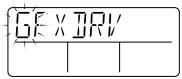
4. Use the pedal module key to bring up the indication "EP-DRV" on the display.
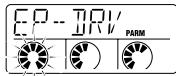
This display allows you to select the effect module to be adjusted in real time with the pedal. RTM control is possible for the DRIVE, MODULATION, and DELAY/REVERB modules. (Several modules can be selected.)
5. Use knobs 1 - 2 on the FX panel 2 to set the following parameters.
Parameter Knob 1 .... EP-DRV
Determines whether to control the DRIVE module with the expression pedal in real time. You can select "oF" (off) or "on".
Parameter Knob 2 .... EP-MOD
Determines whether to control the MODULATION module with the expression pedal in real time. You can select "oF" (off), "UP", "dn" (down), "Hi" (high), or "Lo" (low).
When a setting other than "oF" is selected, operation is as follows.
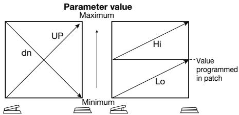

When the effect type of the MODULATION module is PDLPIT (pedal pitch) or PDLWAH (pedal wah), the "Hi" setting has the same effect as "UP" and "Lo" has the same effect as "dn".
Parameter Knob 3--- EP-D/R
Determines whether to control the DELAY/REVERB module with the expression pedal in real time. You can select "oF" (off), "UP", "dn" (down), "Hi" (high), or "Lo" (low).
When a setting other than "oF" is selected, operation is the same as for EP-MOD.
- Make sure that modules selected in step 5 are set to on. If required, switch the effect type used in the module.
The parameter controlled by RTM depends on which effect type is currently selected for the module. For details, see the section "Effect Types and Parameters".
- If required, store the patch, and return to program mode.
When you now operate the expression pedal, the respective parameter in the modules selected for RTM will change.
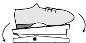
Move pedal
When you push the expression pedal fully down, the assignable switch performs the selected function (switching between program mode and manual mode or toggling the module on/off status).
Press down

For example, you may select the DRIVE and MODULATION modules for RTM control and store the patch with one module set to on and the other set to off. If you then select the module on/off function for the assignable switch, the module controlled by RTM is switched every time you push the expression pedal fully down.
PEDAL WAH/PEDAL PITCH Key
Among the effect types that can be controlled by RTM, the two effect types PDLWAH (pedal wah) and PDLPIT (pedal pitch) in the MODULATION module have a special key.
- In manual mode or program mode, press the PEDAL WAH/PEDAL PITCH keys.
The PEDALWAH/PEDAL PITCH key are shortcut keys for quickly adjusting pedal wah or pedal pitch. With each push of the key, the edit display for "PDLWAH" and "PDLPIT" is displayed alternately.
Lit when type has changed
- To use the pedal wah effect, select the "PDLWAH" display. To use the pedal pitch effect, select the "PDLPIT" display.
When one of these is selected, the patch setting automatically becomes as follows.
- MODULATION module = ON
- MODULATION module effect type = PDLWAH or PDLPIT
-
UP if RTMSET display EP-MOD parameter = oF
-
If required, use the parameter knobs on FX panel 2 to set the effect parameter.
The effect parameter setting procedure is the same as for regular editing. (For information on effect parameters, see page 21.)
- If required, store the patch, and then return to program mode.
When you now operate the expression pedal, the pedal wah or pedal pitch effect is applied.
Effect Types and Parameters
In this section, the effect types and parameters in all modules are listed and explained.
This mark indicates that the parameter can be controlled with the RTM function.
About Modules and Effect Types
The illustration below shows the modules in the patches of the GFX-4, and the effect types that can be selected within each module.
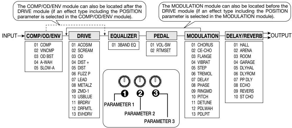
COMP/OD/ENV
COMP/OD/ENV module
Contains effect types such as compressor, booster, envelope (auto wah, slow attack etc.).
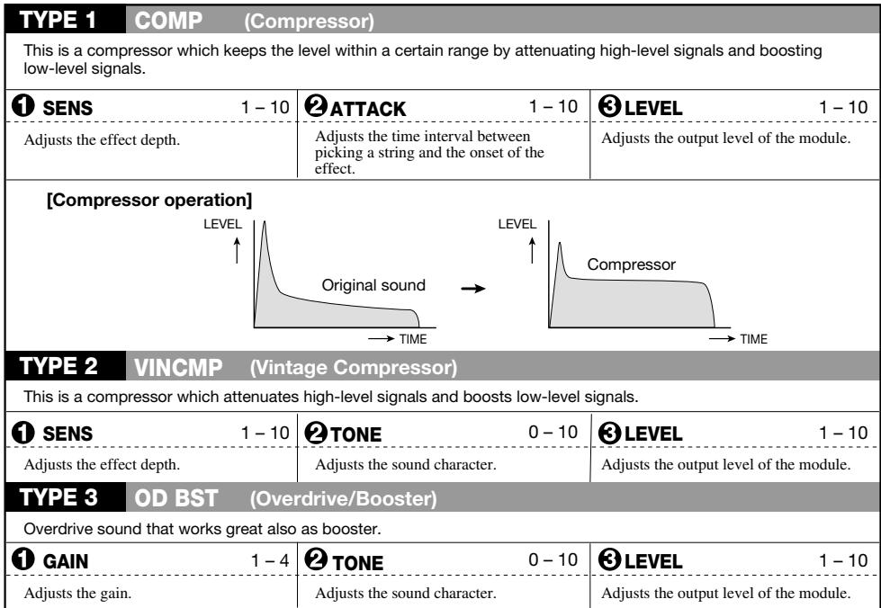
| TYPE 4 | A-WAH (Auto Wah) | ||
| This is an auto wah effect which varies the effect depth according to the picking intensity. | |||
| 1 SENS | -10 -- 1, 1 - 10 | 2 RESO | 1 - 10 |
| Adjusts the sensitivity. Positive values shift the peak upwards and negative values shift it downwards. | Adjusts the prominence of the wah effect. | Selects the COMP/OD/ENV module and DRIVE module connection sequence. The following two settings are available. bF: COMP/OD/ENV → DRIVE AF: DRIVE → COMP/OD/ENV | |
| TYPE 5 | SLOW-A (Slow attack) | ||
| This effect adds a soft attack to each note, depending on the picking intensity. | |||
| 1 TIME | 1 - 10 | 2 CURVE | 1 - 4 |
| Adjusts the transient rate of the sound. | Adjusts the transient curve of the sound. | Selects the COMP/OD/ENV module and DRIVE module connection sequence. The following two settings are available. bF: COMP/OD/ENV → DRIVE AF: DRIVE → COMP/OD/ENV | |
DRIVE
DRIVE module
This module contains mainly distortion type effects such as Fuzz and Overdrive simulating conventional compact effects. In addition, the module also features preamp effects and an acoustic guitar simulator.
| TYPE 1 | ACOSIM (Acoustic Simulator) | ||
| Changes the sound of an electric guitar to resemble that of an acoustic guitar. | |||
| TOP 1 - 10 | BODY 1 - 10 | LEVEL 1 - 10 | |
| Higher values for this parameter result in a stronger acoustic guitar character. | Higher values for this parameter result in stronger instrument body sound. | Adjusts the output level of the module. | |
| TYPE 2 | SCREAM (Scream) | ||
| Simulates a vintage overdrive that was extremely popular in America as a booster. | |||
| TYPE 3 | OD (Overdrive) | ||
| Simulates the "classic" overdrive tone. | |||
| TYPE 4 | DIST + (Distortion +) | ||
| Simulates a vintage distortion unit that pioneered distortion sound. | |||
| TYPE 5 | DIST (Distortion) | ||
| Hard distortion British "Stack Style". | |||
| TYPE 6 | FUZZ P (Fuzz π) | ||
| Vintage "60's" fuzz simulation, rough distortion and superb tone. | |||
| TYPE 7 | LEAD (Lead) | ||
| Parallels the "ZOOM" lead guitar sound, modern with outstanding drive. | |||
| TYPE 8 | METALZ (Metal Z) | ||
| Simulates intense Heavy Metal dual gain distortion. | |||
| TYPE 9 | ZMD-1 (ZOOM Metal Driver 1) | ||
| Ultra high gain, metal super distortion, over the edge. | |||
| TYPE 10 | USBLUE (US Blues) | ||
| Full range vintage amp distortion, picking intensity varies the overdrive. | |||
| TYPE 11 | BRDRV (British Drive) | ||
| The "British Invasion" vintage tube sound that started it all. | |||
| TYPE 12 DRFMTL (DRF Metal) | |||
| Simulates an amp tailor-made for thrashers. The strong distortion goes great together with humbucker pickups. | |||
| TYPE 13 EVHDRV (EVH Driver) | |||
| Simulates a signature amp that has received praise from guitars the world over. | |||
| 1 GAIN 1 - 30 | 2 TONE 0 - 10 | 3 LEVEL 1 - 10 | |
| Adjusts the distortion intensity. | Adjusts the sound character. | Adjusts the output level of the module. | |
EQUALIZER
EQUALIZER module
This module is a 3-band equalizer for adjusting the tonal character of the sound.
| TYPE 1 | 3BAND EQ (3-band equalizer) | ||
| 1 HIGH | -12 - 12 | 2 MID | -12 - 12 |
| Adjusts boost/cut in the high frequency range. | Adjusts boost/cut in the medium frequency range. | Adjusts boost/cut in the low frequency range. | |
PEDAL VOLUME
PEDAL module
This module contains the settings for the expression pedal on the unit.

Because the PEDAL module is not an effect, it cannot be set to off.
| PAGE 1 VOL-SW (Volume/Assignable Switch Settings) | |||
| Determines whether the expression pedal is used as a volume pedal, and determines which function is assigned to the assignable switch. | |||
| EXPVOL oF, on | MINVOL 0-9 | EXP-SW 0,1 | |
| Determines for each patch whether the expression pedal is assigned to volume control. | Determines the minimum volume setting when the expression pedal is assigned to volume control. (This is the volume when the pedal is fully raised.) | Determines for each patch the function that is assigned to the assignable switch. The following two settings are available. 0: On/off switching of module to which RTM is assigned 1: PRESET group program mode/manual mode switching | |
| PAGE 2 RTMSET (RTM Settings) | |||
| Using the RTM function, the DRIVE, MODULATION, or DELAY/REVERB module can be controlled with the expression pedal. | |||
| EP-DRV oF, on | MOD oF, UP, dn, Hi, Lo | EP-D/R oF, UP, dn, Hi, Lo | |
| Determines whether to control a DRIVE module parameter in real time with the expression pedal. When the effect type ACOSIM is selected, the TOP parameter is adjusted. When another effect type is selected, the GAIN parameter is adjusted. | Determines whether to control a MODULATION module parameter in real time with the expression pedal. For details on operation when various settings are selected, see page 19. | Determines whether to control a DELAY/REVERB module parameter in real time with the expression pedal. For details on operation when various settings are selected, see page19. | |
| TYPE 1 CHORUS (Chorus) | |||
| Chorus effect with clear sound. | |||
| 1 DEPTH 0-50 | 2 RATE 1-50 | 3 MIX 0-50 | |
| Adjusts the effect depth. | Adjusts the modulation rate. | Adjusts the effect sound mixing ratio. | |
| [Chorus operation] PITCH + 0 - | Original sound + 0 - | Effect sound → TIME | |
| TYPE 2 CE-CHO (CE Chorus) | |||
| Simulates a vintage analog chorus characterized by warm, full-bodied sound. | |||
| 1 DEPTH 0-50 | 2 TONE 0-10 | 3 MIX 0-50 | |
| Adjusts the effect depth. | Adjusts the effect sound character. | Adjusts the effect sound mixing ratio. | |
| TYPE 3 FLANGE (Flanger) | |||
| This effect produces a unique, undulating sound. | |||
| 1 DEPTH 0-50 | 2 RATE 1-50 | 3 RESO -15-15 | |
| Adjusts the effect depth. | Adjusts the modulation rate. | Adjusts the character intensity. Negative values result in effect sound with reversed phase. | |
| TYPE 4 VIBRAT (Vibrato) | |||
| This is a vibrato effect that periodically varies the pitch. | |||
| 1 DEPTH 0-50 | 2 RATE 1-50 | 3 BAL 0-50 | |
| Adjusts the effect depth. | Adjusts the modulation rate. | Adjusts the mixing balance between effect sound and original sound. Higher values result in stronger effect sound. | |
| TYPE 5 STEP (Step) | |||
| This is a special effect with step-like filter characteristics. The cutoff is varied in discrete steps at a constant rate, resulting in a sample-and-hold type effect. | |||
| 1 DEPTH 0-50 | 2 RATE 1-50 | 3 FB 0-50 | |
| Adjusts the effect depth. | Adjusts the modulation rate. | Adjusts the feedback amount. | |
| TYPE 6 TREMOL (Tremolo) | |||
| This effect periodically varies the level of the sound. | |||
| 1 DEPTH 0-50 | 2 RATE 1-50 | 3 CLIP 0-10 | |
| Adjusts the effect depth. | Adjusts the modulation rate. | Higher values result in clipped modulation signal waveform, which emphasizes the modulation. | |
| [Tremolo operation] LEVEL + 0 - | Original sound + 0 - | Signal after tremolo effect TIME | |
| TYPE 7 DELAY (Delay) | |||
| This is a delay effect with a maximum delay time of 500 milliseconds. | |||
| 1 TIME 1-50 | 2 FB 0-50 | 3 MIX 0-10 | |
| Adjusts the delay time in 10-ms steps. | Adjusts the feedback amount. Higher values result in an increased number of delayed sound components. | Adjusts the effect sound mixing ratio. | |
| TYPE 8 PHASE (Phaser) | |||
| Simulates a phaser with silky smooth sound not attained by other models. | |||
| 1 POSI bF, AF | 2 RATE 1-50 | 3 COLOR 1-4 | |
| Selects the connection position of the MODULATION module. The following two settings are available. bF: Before the DRIVE module AF: After the EQUALIZER module | Adjusts the modulation rate. | Selects the character of the phase sound. | |
| TYPE 9 RINGMD (Ring Modulation) | |||
| This effect applies amplitude modulation to the input signal, resulting in a metallic sound character. | |||
| 1 POSI bF, AF | 2 FREQ 1-50 | 3 BAL 0-50 | |
| Selects the connection position of the MODULATION module. The following two settings are available. bF: Before the DRIVE module AF: After the EQUALIZER module | Determines the frequency of the modulation signal. | Adjusts the mixing balance between effect sound and original sound. Higher values result in stronger effect sound. | |
| TYPE 10 PITCH (Pitch Shifter) | |||
| This effect varies the pitch in the range from 1 octave down to 2 octaves up. | |||
| 1 PIT -12, -11...-1, 1, 2... 12, 24 | 2 TONE 0-10 | 3 BAL 0-50 | |
| Adjusts the pitch shift amount in semitone steps. | Adjusts the effect sound character. | Adjusts the mixing balance between effect sound and original sound. Higher values result in stronger effect sound. | |
| TYPE 11 DETUNE (Detune) | |||
| This effect mixes a slightly pitch-shifted component to the original sound, resulting in a chorus effect with only slight modulation. | |||
| 1 DEPTH -10...-1, 1...10 | 2 TONE 0-10 | 3 MIX 0-50 | |
| Adjusts the effect sound detuning extent. | Adjusts the effect sound character. | Adjusts the effect sound mixing ratio. | |
| TYPE 12 PDLWAH (Pedal Wah) | |||
| Simulates a typical pedal wah with changing effect and feeling according to the pedal angle. | |||
| 1 POSI bF, AF | 2 FREQ 1-50 | 3 LEVEL 1-50 | |
| Selects the connection position of the MODULATION module. The following two settings are available. bF: Before the DRIVE module AF: After the EQUALIZER module | Adjusts the wah center frequency. | Adjusts the volume level. | |
| TYPE 13 PDLPIT (Pedal Pitch) | |||
| This is a pitch shifter controlled by the pedal. | |||
| 1 POSI bF, AF | 2 TYPE 1-10 | 3 TONE 0-10 | |
| Selects the connection position of the MODULATION module. The following two settings are available. bF: Before the DRIVE module AF: After the EQUALIZER module | Selects the pedal pitch type. | Adjusts the effect sound character. | |
| [Pedal pitch type] | |||
| TYPE | PEDAL WAH/PEDAL PITCH key For the effect types PDLWAH (pedal wah) and PDLPIT (pedal pitch) of the MOD module only, there is a special key to call up the edit screen. Pressing the PEDAL WAH/PEDAL PITCH key in manual mode or program mode toggles the unit between the PDLWAH and PDLPIT edit screens. When PDLWAH or PDLPIT is selected, you can adjust the effect parameters with the knobs of FX panel 2. In this case, the following settings are established automatically. • MODULATION module = ON • MODULATION module effect type = PDLWAH or PDLPIT • UP if RTMSET display EP-MOD parameter = oF | ||
| 1 ± 0 cent | -100 cent | ||
| 2 ± 0 cent | +1 octave | ||
| 3 ± 0 cent | +2 octave | ||
| 4 ± 0 cent | -1 octave | ||
| 5 ± 0 cent | -2 octave | ||
| 6 Doubling | Detuned sound + original sound | ||
| 7 -1 octave + original sound | +1 octave + original sound | ||
| 8 -700 cent + original sound | +500 cent + original sound | ||
| 9 -∞ (0 Hz) + original sound | +1 octave | ||
| 10 -∞ (0 Hz) + original sound | +1 octave + original sound | ||
DELAY/ REVERB
DELAY/REVERB module
This module contains various echo effects such as delay and reverb.
| TYPE 1 | HALL (Hall) | ||
| This is a reverb effect which simulates a medium-size concert hall. | |||
| TYPE 2 | ARENA (Arena) | ||
| This is a reverb effect which simulates a large arena. | |||
| TYPE 3 | ROOM (Room) | ||
| This is a reverb effect which simulates a small room. | |||
| TYPE 4 | GARAGE (Garage) | ||
| This is a reverb effect which simulates a garage with a high amount of early reflections. | |||
| 1 REVTIM 1-30 | 2 TONE 0-10 | 3 REVMIX 0-50 | |
| Adjusts the reverb time. | Adjusts the effect sound character. | Adjusts the effect sound mixing ratio. | |
| TYPE 5 | DLYHAL (Delay Hall) | ||
| This is a combined delay + hall reverb effect. | |||
| TYPE 6 | DLYROM (Delay Room) | ||
| This is a combined delay + room reverb effect. | |||
| 1 DLYTIM 1-50 | 2 DLYMIX 0-50 | 3 REVMIX 0-50 | |
| Adjusts the delay time in 10-ms steps. | Adjusts the delay sound mixing ratio. | Adjusts the reverb sound mixing ratio. | |
| TYPE 7 PP DLY (Pingpong Delay) | |||
| This is a pingpong delay effect with a long delay time (maximum 2 seconds). | |||
| TYPE 8 ECHO (Echo) | |||
| This is a warm sounding delay effect with a long delay time (maximum 2 seconds). | |||
| 1 DLYTIM 1-99,1.0-2.0 | FB/HLD 0-50, Hd, HS | DLYMIX 0-50 | |
| Adjusts the delay time in 10-ms steps up to 1 second. Above that, adjustment is in 100-ms steps. | 0-50: Adjusts the delay feedback amount. Hd: Causes the effect to operate as hold delay. HS: Causes the effect to operate as hold delay with seamless function. | Adjusts the delay sound mixing ratio. | |
| Hold Delay [Hold Delay] By selecting PP-DLY or ECHO as the effect type in the DELAY/REVERB module and setting parameter 2 to "Hd" or "Hs", a patch can use the hold delay function where the foot switches serve to control recording and playback of a phrase. • Select the above type of patch in manual mode and press foot switch 3 to start recording. • When foot switch 3 is released or the delay time set as parameter 1 has elapsed, recording terminates, and repeat playback of the recorded phrase starts automatically. • Pressing foot switch 3 during repeat playback stops playback. | Original sound Effect sound Foot switch 3 Press Release Repeat playback Record Delay time Press | Press | |
| Seamless Delay (Patch delay) Using the seamless delay function causes the delay sound from the immediately preceding patch to be heard still after switching patches. | |||
| The seamless delay function of the GFX-4 can be used when both the patches (before and after switching) fulfill all of the following conditions: (1) REV/DLY module = ON (2) REV/DLY module effect type = PP-DLY or ECHO (3) Delay time = Max. 1 second When both the patches (before and after switching) have the REV/DLY module ON and the FB/HLD parameter set to "HS", the hold delay function can be used as seamless delay. In this case, the recorded phrase continues to be repeated also after the GFX-4 is returned to program mode and the patch is switched during repeat playback. To force an end to the hold delay function after a patch change, set the unit to the bypass condition. | [Seamless Delay] LEVEL Patch A Patch B Original sound Delay sound Patch change TIME | ||
| TYPE 9 REVERS (Reverse) | |||
| This is a special delay effect where the effect sound seems to be rotating in reverse. | |||
| 1 DLYTIM 50-99,1.0-2.0 | FB 0-50 | DLYBAL 0-50 | |
| Adjusts the delay time in 10-ms steps up to 1 second. Above that, adjustment is in 100-ms steps. | Adjusts the delay feedback amount. | Adjusts the delay sound mixing ratio. | |
| TYPE 10 ST CHO (Stereo Chorus) | |||
| This is a stereo chorus effect with clear sound and a wide spread. | |||
| 1 DEPTH 0-50 | RATE 1-50 | CHOMIX 0-50 | |
| Adjusts the effect depth. | Adjusts the modulation rate. | Adjusts the chorus sound mixing ratio. | |
Other Functions
This section contains information about special functions such as how to return the GFX-4 to the factory default condition and how to readjust the expression pedal.
All Initialize
The All Initialize function is a special function that lets you reset the GFX-4 to the condition in which it was originally shipped. When All Initialize is performed, all settings of the unit including all user group patches are returned to the default condition.
1. Turn power to the GFX-4 on while keeping the STORE key depressed.
The display shows "INIT".
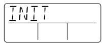
2. Press the STORE key once more.
All Initialize is carried out. If All Initialize was carried out, the unit automatically returns to the program mode.
Note that when All Initialize is executed, the contents of all patches stored by the user will be overwritten (erased). When wishing to cancel All Initialize, press the MANUAL/CANCEL key before step 2.
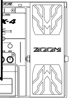
Adjusting the Expression Pedal
The expression pedal of the GFX-4 uses a highly reliable optical sensor mechanism. The pedal is adjusted for optimum operation at the factory, but it can be readjusted as follows if required.
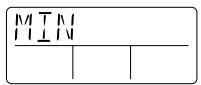
1. Hold down the PEDAL module key while turning on power to the unit.
The indication "MIN" appears on the display.
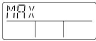
2. With the expression pedal fully raised, press the STORE key.
The display indication changes to "MAX".
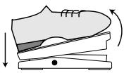

3. Push the expression pedal fully down and then lift your foot off the pedal (the pedal goes back a little). Press the STORE key at this point.
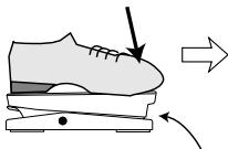
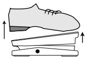
Push strongly, so that pedal touches here
When foot is lifted, pedal returns slightly
Press STORE key

STORE

The adjustment is completed, and the unit returns to the program mode.
Troubleshooting
| Symptom | Check | Remedy |
| No sound or very low volume | ·Is suitable AC adapter connected, and power switch set to ON? | Make connections as described in "Getting Connected" and turn power on. |
| ·Is instrument connected correctly to INPUT jack and playback equipment to OUTPUT jack? | Make connections as described in "Getting Connected". | |
| ·Is shielded cable defective? | Try using another cable. | |
| ·Is amplifier turned on? Are level controls for instrument and amplifier set to proper values? | Turn amplifier on and adjust volume to proper level. | |
| ·Is GFX-4 set to mute condition? | Cancel the mute condition. | |
| ·Is MASTER LEVEL knob turned down? | Set MASTER LEVEL knob to proper position. | |
| ·Is expression pedal raised? | For some patches, the expression pedal controls the volume. Set it to a suitable position. | |
| Bypass (mute) mode cannot be activated | ·Has unit been switched between program mode and manual mode? | Switch function is different in program mode and manual mode. Select correct mode. |
| Volume does not change when expression pedal is operated in bypass mode | ·Has expression pedal been set to function as volume pedal? | Assign volume control function to expression pedal as described on page 19 and set minimum volume. |
| ·Is mono output used (playback system connected only to OUTPUT MONO jack)? | With a mono connection, the expression pedal cannot be used to control the volume. Connect the playback system to OUTPUT STEREO jack. | |
| Expression pedal on/off switching is not performed properly | ·Readjusting the pedal may correct the problem. | Readjust pedal, as described on page 28. |
| Oscillation occurs | ·Is high-gain distortion effect used together with compressor/booster effect or EQUALIZER? | Reduce parameter values of high-gain module (gain, tone, level). |
Specifications
| Effect programs | 44 (42 effects + ZNR + Amp Simulator) | Outputs | Mono output Standard phone jack (mono) x 1 (nominal output level -10 dBm, output impedance 10 kΩ or higher) |
| Effect modules | 6 + ZNR + Amp Simulator | ||
| Patch memory | USER 3 patches x 5 banks x 4 groups = 60 (read/write/store) PRESET 3 patches x 5 banks x 4 groups = 60 (read only) Total 120 patches | Display | Combined line/headphone output Standard phone jack (stereo) x 1 (maximum output level +4 dBm, output load impedance 10 kΩ or higher) |
| Sampling frequency | 40 kHz | Power requirements | Original LCD (with backlight) 2-digit, 7-segment LED |
| A/D conversion | 20-bit 64-times oversampling converter | ||
| D/A conversion | 20-bit 128-times oversampling converter | Dimensions | 397 mm (W) x 183 mm (D) x 60 mm (H) |
| Input | Guitar input Standard phone jack (mono) x 1 (nominal input level -10 dBm) | Weight | 1.4kg |
| * 0 dBm = 0.775 Vrms * Design and specifications subject to change without notice. | |||
| Pickup select | Normal Input impedance 510kΩ (pickup type = passive) Active Input impedance 20 kΩ (pickup type = active) | ||
| GROUP | BANK | PATCH | NAME | DEMO |
| A | 0 | 1 | GFXDRV | Powerful distortion sound. |
| 2 | ODROCK | Boost sound with over drive effect. | ||
| 3 | STDCHO | Useful chorus sound. | ||
| 1 | 1 | HEAVY | Heavy base distortion sound. | |
| 2 | FUSION | Vintage comp and phase effect combined sound. | ||
| 3 | PDLPIIT [PEDAL-PITCH] | Hard distortion with pedal-pitch effect. | ||
| 2 | 1 | MTLDLY | Metal sound with delay effect. | |
| 2 | COOLWA [PEDAL-WAH] | Vintage pedal-wah clean sound. | ||
| 3 | TEXAS | Over drive sound for "blues-man". | ||
| 3 | 1 | WAHDST [PEDAL-WAH] | Distortion sound with pedal-wah effect. | |
| 2 | BLUES | Good for blues playing. | ||
| 3 | FUNKY | Funky auto-wah sound. | ||
| 4 | 1 | LABACK | Good for riff playing. | |
| 2 | STRUM | Acoustic guitar simulated for strum play. | ||
| 3 | RNGDRV | Lead sound with ring modulation effect. | ||
| GROUP | BANK | PATCH | NAME | MODELING |
| b | 0 | 1 | BOTTOM | Heavy fuzz sound with chorus effect. |
| 2 | NIRVRN | High gain grungy sound. | ||
| 3 | SMOOOTH | Smooth chorus clean sound. | ||
| 1 | 1 | CMB335 | Like Larry's "room". | |
| 2 | C-GROV | Doobie's American rock sound. | ||
| 3 | OCTAVE | Clean sound with octave effect. | ||
| 2 | 1 | FUZRVS [PEDAL-WAH] | Fuzz drive sound, with pedal-wah and reverse effect. | |
| 2 | X-ROCK | Metal sound, pedal controls pitch-shifter mix. | ||
| 3 | OLDCUT | For clean cutting sound. | ||
| 3 | 1 | PANAMA | Eddie's famous driven sound. | |
| 2 | HYLOW | Boost sound with high gain distortion effect. | ||
| 3 | NUANCE | Real amplifier sound. | ||
| 4 | 1 | BRNWTR | Modern Fuzz tone. | |
| 2 | SNAKE | Hard rock sound. | ||
| 3 | ROCKER | Distortion sound for standard rock style. | ||
| GROUP | BANK | PATCH | NAME | STANDARD / ARTIST |
| c | 0 | 1 | BZ-TAK | Tak's wah tone. |
| 2 | VAIDRV | Vai's driven sound. | ||
| 3 | CHODRV | Distortion sound with chorus effect. | ||
| 1 | 1 | VAI-LD | Vai's lead sound. | |
| 2 | GARY | Gary's lead sound. | ||
| 3 | ZAK | Zak's auto-wah sound. | ||
| 2 | 1 | SCOHEN | Lead sound for Jazz/fusion style. | |
| 2 | PATONE | Clean tone for jazz play. | ||
| 3 | JAZZOD | Over drive sound for jazz play. | ||
| 3 | 1 | LUKIE | Luke's all-round sound. | |
| 2 | SUMMER | Message in a "sound". | ||
| 3 | SATCH | Like Satch's "ALIEN". | ||
| 4 | 1 | LA-STD | LA studio sound simulation. | |
| 2 | BMSTEP | Zoom original step effect sound. | ||
| 3 | EVH2 | Eddie's famous hard driven sound. | ||
| GROUP | BANK | PATCH | NAME | VARIATION |
| d | 0 | 1 | HMSOLO [PEDAL-PITCH] | Distortion sound with pedal-pitch effect. |
| 2 | MARK2 | Combo AMP style sound simulation. | ||
| 3 | UKTONE | Old UK-style sound. | ||
| 1 | 1 | VISUAL | Chorus driven sound. | |
| 2 | ROCKAB | Rockabilly sound. | ||
| 3 | ALPTRM | Clean sound with tremolo effect. | ||
| 2 | 1 | RICH | Rich distortion sound. | |
| 2 | CONTRY | Crunch sound for Country blues style. | ||
| 3 | CATHED | Slow attack sound for lead play. | ||
| 3 | 1 | TRIBAL | Classic chorus with distortion sound. | |
| 2 | WORMMY | Box style cabinet clean sound. | ||
| 3 | MELOW | Detune chorus clean sound. | ||
| 4 | 1 | DRVIBE | Drive sound with vibrato effect. | |
| 2 | JET | Standard jet sound. | ||
| 3 | ROBOT | Robot voice sound with pick-noise play. |
- ZNR(Zoom Noise Reduction) parameter in each patch should be adjusted for optimum matching the with your guitar.
- In the factory default condition, the contents of the user patches and preset patches are the same.
- RTM (Real Time Modulation) assigned for all-patches.
Creating Your Own Sound
This section gives some pointers on how to get optimum performance from the unit. Use these hints as starting points to explore the GFX-4 capabilities to the max.
- Compact distortion 2-stage sound
This is a frequently used setting for playing a solo with the same sound character as the backing, but with more distinct, solid sound.
Normally, the first stage will provide OD distortion with moderate gain and high level, and the second stage will be used to create the main distortion.

Take care not to apply excessive distortion, because this setting places a considerable load on the circuits and can lead to oscillation.
[Sample Patches]
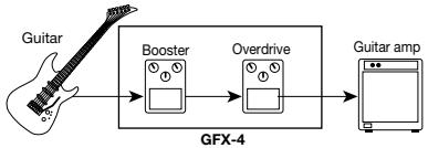
A02:ODROCK
Example for booster + overdrive combination
A11: HEAVY
Example for booster + high-gain distortion combination
- Technique for obtaining detailed distortion using a compact effect and tube amp
This kind of setup is frequently used by professional guitarists to further increase the distortion from the guitar amplifier.
The GFX-4 makes it easy to duplicate this setup, because the unit also features famous guitar amplifier sounds. The technique can be applied also when not playing at loud levels, such as during MTR recording. The amp simulator will be useful in such cases.
[Sample Patches]
A01: GFXDRV
This uses light compression to extend sustain. Enhances playing through a stack amp.
A23: TEXAS
Setting example for the sound of a famous late blues guitarist from Texas. Adds punch to a combo amplifier.
- How to make optimum use of effect connection sequence
The sonic impression created by an equalizer type
effect such as wah differs greatly, depending on whether it is inserted before or after the distortion in the signal path. When inserted before the distortion, it emphasizes the point on which distortion is applied. When inserted after the distortion, equalization acts upon the entire sound.
The GFX-4 provides 2 effects in the COMP/OD/ENV module and 4 effects in the MODULATION module for which the connection point can be switched.
[Sample Patches]
C01: BZ-TAK
Setting example for inserting wah as equalizer before distortion
C33: SATCH
Setting example for inserting phaser as equalizer before distortion
- Using vintage effect sounds
The sound of many vintage effect devices still is very attractive also in the digital age. Mastering the use of such sounds will help you find your individual style. For best results, avoid excessive distortion and let the sound character of the selected device speak for itself.
[Sample Patches]
A12:FUSION
This is a vintage compressor and phaser sound.
A22:COOLWA
Setting example for a vintage pedal wah sound
b02:NIRVRN
Setting example for obtaining modern sound with a vintage distortion effect
b21: FUZRVS
Setting example for a combination of vintage fuzz ^+ vintage wah ^+ reverse-rotation delay
- Expression pedal secrets
The expression pedal of the GFX-4 incorporates a nifty feature called assignable switch (see page 19). The switch can be used to toggle between program mode and manual mode. This enhances your flexibility during a performance, because in manual mode, it is possible to turn separate compact effects on and off with the foot switches. For example, you can use the feature to turn a modulation effect on and off or control other the sound in other ways offered by manual mode.
[Sample Patch]
C23: JAZZOD
May be used also in manual mode only.
ZEM
ZOOM CORPORATION
NOAH Bldg., 2-10-2, Miyanishi-cho, Fuchu-shi, Tokyo 183-0022, Japan
PHONE: +81-42-369-7116 FAX: +81-42-369-7115
Web Site: http://wwwzoomo.co.jp
- Safety Precautions/Usage Precautions 2
- Introduction 3
- Terms Used in This Manual 4
- Controls and Functions 5
- Getting Connected 6
- Preparations 7
- Operation Guide 1 Selecting Patches for Playing 8
- Operation Guide 2 Editing Patches 10
- Operation Guide 3 Storing/Swapping Patches 12
- Operation Guide 4 Using the Tuner (Bypass/Mute) Function 14
- Editing Operations 16
- Effect Types and Parameters 21
- Other Functions 28
- Troubleshooting 29
- Specifications 29
- Patch List 30
- Creating Your Own Sound 31
- Safety Precautions/Usage Precautions
- Safety Precautions
- Power requirements
- Environment
- Handling
- - Alterations
- Usage Precautions
- - Electrical interference
- - Cleaning
- - Versatile array of effects
- Great choice of distortion sounds
- Designed to get the best out of any guitar
- Simple and intuitive operation
- Extensive patch library
- Great for use on stage
- Terms Used in This Manual
- Module
- Effect types and parameters
- Patch/group/bank
- Modes
- Program mode
- - Manual mode
- - Store mode
- - Bypass/mute mode
- Special mode
- RTM (real-time modulation)
- Controls and Functions
- Top Panel
- Rear Panel
- Guitar amp/instrument connection
- About the Mono Output
- When using effects
- When using Bypass
- Power Up
- Using the Amp Simulator
- Operation Guide 1 Selecting Patches for Playing
- Turn on the power
- Select the bank
- Select the patch
- Select the group
- Use the pedal
- Operation Guide 2 Editing Patches
- Select module to edit
- Use the module keys to select the module that you want to edit.
- Switch effect modules on and off
- To toggle the selected module between on and off, press the FX panel key corresponding to that module.
- Operation Guide 3 Storing/Swapping Patches
- Switch the GFX-4 to store mode
- In program mode or manual mode, press the STORE key.
- Select the store target patch
- Select whether to store or swap the patch
- Carry out the store/swap process
- Operation Guide 4 Using the Tuner (Bypass/Mute) Function
- Set the GFX-4 to bypass (mute)
- Tune your guitar
- Adjust the reference pitch of the tuner
- Return to program mode
- Editing Operations
- While the GFX-4 is in program mode, select the patch you want to edit.
- Press one of the module keys (COMP/OD/ENV, DRIVE, EQUALIZER, PEDAL, MODULATION, DELAY/REVERB) to select the target module.
- To toggle the selected module between on and off, press the module key of the corresponding FX panel again.
- To switch the effect type of the selected module, use the TYPE DOWN/UP keys on the corresponding FX panel.
- To set the effect parameters of the selected module, operate parameter knobs 1 - 3 of the corresponding FX panel.
- Operation Differences of Manual Mode and Program Mode
- Setting the Patch Level and Patch Name
- Setting the ZNR Threshold
- Using the Expression Pedal (RTM function)
- Select the patch for which you want to make RTM settings, and press the PEDAL module key in manual mode or program mode.
- Use the pedal module key to bring up the indication "EXPVOL" on the display.
- Use knobs 1 - 3 of FX panel 2 to set the following parameters.
- Use the pedal module key to bring up the indication "EP-DRV" on the display.
- Use knobs 1 - 2 on the FX panel 2 to set the following parameters.
- PEDAL WAH/PEDAL PITCH Key
- About Modules and Effect Types
- COMP/OD/ENV
- COMP/OD/ENV module
- DRIVE
- DRIVE module
- EQUALIZER
- EQUALIZER module
- PEDAL VOLUME
- PEDAL module
- DELAY/REVERB module
- Other Functions
- All Initialize
- Turn power to the GFX-4 on while keeping the STORE key depressed.
- Press the STORE key once more.
- Adjusting the Expression Pedal
- Hold down the PEDAL module key while turning on power to the unit.
- With the expression pedal fully raised, press the STORE key.
- Push the expression pedal fully down and then lift your foot off the pedal (the pedal goes back a little). Press the STORE key at this point.
- Troubleshooting
- Specifications
- Creating Your Own Sound
- - Compact distortion 2-stage sound
- [Sample Patches]
- - Technique for obtaining detailed distortion using a compact effect and tube amp
- - How to make optimum use of effect connection sequence
- - Using vintage effect sounds
- - Expression pedal secrets
- [Sample Patch]
- ZEM
Brand : ZOOM
Model : GFX4
Category : Guitar Effects