
GS-10 - Guitar Effects BOSS - Free user manual and instructions
Find the device manual for free GS-10 BOSS in PDF.
| Product Type | Guitar effects processor with USB audio interface |
| Brand | BOSS |
| Model | GS-10 |
| Power Supply | BRC series AC adapter (included) |
| Power Consumption | Not specified (estimated: 15 W) |
| Number of Patches | 200 (100 user, 100 preset) |
| Effect Types | COSM preamp/speaker, compressor, overdrive/distortion, delay, chorus, reverb, EQ, FX-1, FX-2 |
| Input Connectors | GUITAR/BASS (6.35 mm jack), MIC INPUT (XLR and balanced 6.35 mm jack), AUX INPUT (L/R, 6.35 mm jack) |
| Output Connectors | OUTPUT L/R (6.35 mm jack), GUITAR AMP OUT (6.35 mm jack), DIGITAL OUT (coaxial), PHONES (stereo 6.35 mm jack) |
| USB Interface | USB B for connection to computer (audio and MIDI) |
| MIDI | MIDI input and output (DIN 5-pin) |
| External Pedals | EV-5 expression pedal (optional), FS-5U foot switch (optional) |
| Built-in Speakers | Yes, stereo, on/off button |
| Built-in Tuner | Yes, chromatic |
| Included Software | GS-10 Editor, GS-10 Librarian, USB driver |
| Dimensions (approx.) | Not specified (estimated: 350 x 250 x 100 mm) |
| Weight (approx.) | Not specified (estimated: 3 kg) |
| Maintenance and Cleaning | Soft, dry cloth. Do not use solvents or alcohol-based products. |
| Safety | Read safety instructions (pages 2-3 of the manual). Do not open the device. Use only the supplied adapter. |
| Spare Parts and Repairability | Contact an authorized BOSS/Roland service center. |
| General Information | 180-page manual in French. Warranty: refer to the provided document. |
Frequently Asked Questions - GS-10 BOSS
User questions about GS-10 BOSS
0 question about this device. Answer the ones you know or ask your own.
Ask a new question about this device
Download the instructions for your Guitar Effects in PDF format for free! Find your manual GS-10 - BOSS and take your electronic device back in hand. On this page are published all the documents necessary for the use of your device. GS-10 by BOSS.
USER MANUAL GS-10 BOSS
Copyright © 2003 BOSS CORPORATION
OD/DS (Saturation/Distortion) 32
DELAY 33
CHORUS. 34
REVERB 34
EQ (Égaliseur) 35
FX-1. 36
PW (Pédale wah-wah). 36
RT (Son rotatif). 47
SDD (Delay court) 48
HU (Humanizer). 48
SL (Slicer) 49
AR (AutoRiff). 49
Activation/désactivation du monitoring direct. 79
Affectation du signal de sortie/monitoring direct (Dir Monitor) 79
Pilote (driver) USB compatible WDM/ASIO
(Overdrive/Distortion)
DRIVE
FEEDBACK (retroaction)
12. ASSIGN (affection) (p. 60)
OUTPUT: Select Line/Phones
Input Select.
Guitar
OD/DS (Overdrive/Distortion) DRIVE
OD/DS (Overdrive/Distortion) LEVEL:
Quick OD/DS
P01:FAT BOOSTER
Quick OD/DS ----User Setting
On/Off (effet On/Off)
Active/désactive l'effet PREAMP/SPEAKER.
CH Select (sLECTION du canal)
On/Off (activation/désactivation)
OD/DS (Overdrive/Distortion)
| Paramètre | Valeur |
| On/Off | Off, On |
| Type | refer to below |
| Drive | 0-100 |
| Bass | -50-+50 |
| Treble | -50-+50 |
| Effect Level | 0-100 |
| Direct Level | 0-100 |
On/Off (activation/désactivation)
Active/désactive l'effet OD/DS.
Type
On/Off (activation/désactivation)
Active/désactive l'effet DELAY.
Type
Feedback (retroaction)
On/Off (activation/désactivation)
Active/désactive l'effet CHORUS.
Mode
On/Off (activation/désactivation)
Active/désactive l'effect REVERB.
Type
| Paramètre | Valeur |
| On/Off | Off, On |
| Low EQ | -20 dB—+20 dB |
| Lo-Mid f | 20.0 Hz–10.0 kHz |
| Lo-Mid Q | 0.5–16 |
| Lo-Mid EQ | -20 dB—+20 dB |
| Hi-Mid f | 20.0 Hz–10.0 kHz |
| Hi-Mid Q | 0.5–16 |
| Hi-Mid EQ | -20 dB—+20 dB |
| High EQ | -20 dB—+20 dB |
| Level | -20 dB—+20 dB |
On/Off (activation/désactivation)
On/Off (activation/désactivation)
Active/désactive l'effect FX-1.
FX Select (sLECTION d'effet)
Release (amortissement)
On/Off (activation/désactivation)
Active/désactive le multi-effet FX-2 effect.
FX Select (sLECTION d'effet)
Pre Delay (pré-delay)
Feedback (retroaction)
Pre Delay (pré-delay)
| User1 | STEP | OUT |
| IN:C | 1 | C |
Release (atténuation)
| Character | Loose, Tight |
| Level | 0–100 |
| Paramètre | Valeur |
| Low EQ | -20 dB—+20 dB |
| Lo-Mid f | 20.0 Hz–10.0 kHz |
| Lo-Mid Q | 0.5–16 |
| Lo-Mid EQ | -20 dB—+20 dB |
| Hi-Mid f | 20.0 Hz–10.0 kHz |
| Hi-Mid Q | 0.5–16 |
| Hi-Mid EQ | -20 dB—+20 dB |
| Hi EQ | -20 dB—+20 dB |
| Level | -20 dB—+20 dB |
On/Off (activation/désactivation)
Release (atténuation)
Target: Master BPM (Tap)
Target Min: Off
Target Max: On
Source: CTL 1 (ou CTL 2)
Source Mode: Normal
Act.Range Lo: 0
Act.Range Hi: 127
EDIT CUSTOM PRE1 Type JC Clean
PreamSP On SP Type Custom 1
EDIT CUSTOM SP 1 Speaker Size 12"
EDIT CUSTOM DS 1 Type DD-1
Bottom (distorsion graves)
Pedal Wah On
Type Custom 1
EDIT CUSTOM WAH1 Type CRY WAH
SYS:EXP PDL Func Auto
SYS:CTL2 Func
Tuner On/Off
Quick ASSIGN1 ----User Setting
Target (destination)
ASSIGN 1 Target
FU : Level
ASSIGN 1 Target Min: 0
ASSIGN 1 Target Max: 100
ASSIGN 1 Source EXP PEDAL
Source Mode (mode source)
ASSIGN 1 Source Mode: Normal
Active Range (plage active)
ASSIGN 1 Source Act. Range Lo:0
ASSIGN 1 Source Act. Range Hi:127
Source: CTL1 (or CTL2)
Mode: Toggle
Act. Range Lo: 0
Act. Range Hi: 1-127
SYS:Knob Mode Immediate
MIDI:RX Channel
Channel = 1
MIDI:Omni Mode Omni On
TX Channel (canal de transmission)
MIDI:Device ID ID = 17
MIDI:Sync Clock Auto
MIDI:KnobCtrl1Out On
MIDI:EXP PDL Out CC# 7
MIDI:Bulk Load Waiting...
MIDI:Bulk Load Receiving...
| STOP | 90 00 00 90 02 01 90 02 00 90 00 00 FC |
| START | 90 00 00 90 04 01 90 04 00 90 00 00 FA |
Activation/désactivation du monitoring direct
Input Select.
Guitar
Battery Low !! Please Change
SP Type, Mic Type, Mic Dis., Mic Pos., Mic Level, Direct Level
OUTPUT Select: Line/Phones
Knob Mode: Immediate
EXP PDL Func: Auto
CTL1 Func: Assign 1-8
CTL2 Func: Assign 1-8
MIDI
RX Channel: 1
Omni Mode: Omni On
TX Channel: Rx
Device ID: 17
Sync Clock: Auto
Remote Ctrl: Advanced
KnobCtrlOut: On
PC Out: On
EXP PDL Out: CC#7
CTL1 Out: Off
CTL2 Out: Off
Map Select: Fix
USB
Output Level: 100
Input Level: 100
Monitor Cmd: Disable
Dir Monitor: On
Output Mode: Stereo (L/R)
Driver Mode: Advanced
Std.Drv Func: Audio
Autres
Speaker ON/OFF: ON
Mic Gain: 50
Roland's MIDI implementation uses the following data format for all Exclusive messages (type IV):
| Byte | Description |
| F0H | Exclusive Status |
| 41H | Manufacturer ID (Roland) |
| DEV | Device ID |
| MDL | Model ID |
| CMD | Command ID |
| [BODY] | Main data |
| F7H | End of exclusive |
-MIDI status: F0H, F7H
An Exclusive message must be flanked by a pair of status codes, starting with a Manufacturer ID immediately after F0H (MIDI version 1.0).
Manufacturer ID: 41H
The Manufacturer ID identifies the manufacturer of a MIDI instrument that sends an Exclusive message. Value 41H represents Roland's Manufacturer ID.
Device ID: DEV
The Device ID contains a unique value that identifies individual devices in the implementation of several MIDI instruments. It is usually set to 00H-0FH, a value smaller by one than that of a basic channel, but value 00H-1FH may be used for a device with several basic channels.
- Model ID: MDL
The Model ID contains a value that identifies one model from another. Different models, however, may share an identical Model ID if they handle similar data.
The Model ID format may contain 00H in one or more places to provide an extended data field. The following are examples of valid Model IDs, each representing a unique model:
01H□ 02H□ 03H□ 00H,01 00H,02 00H,03
Command ID:CMD
The Command ID indicates the function of an Exclusive message. The Command ID format may contain 00H in one or more places to provide an extended data field. The following are examples of valid Command IDs, each representing a unique function:
01H□
02H□
03H□
00H,01H□
00H,02H□
00H,00H,01H□
- Main data: BODY
This field contains a message to be exchanged across an interface. The exact data size and content will vary with the Model ID and Command ID.
2. Address-mapped Data Transfer
Address mapping is a technique for transferring messages conforming to the data format given in Section 1. It assigns a series of memory-resident records—waveform and tone data, switch status, and parameters, for example, to specific locations in a machine-dependent address space, thereby allowing access to data residing at the address a message specifies.
Address-mapped data transfer is therefore independent of models and data categories. This technique allows use of two different transfer procedures: one-way transfer and handshake transfer.
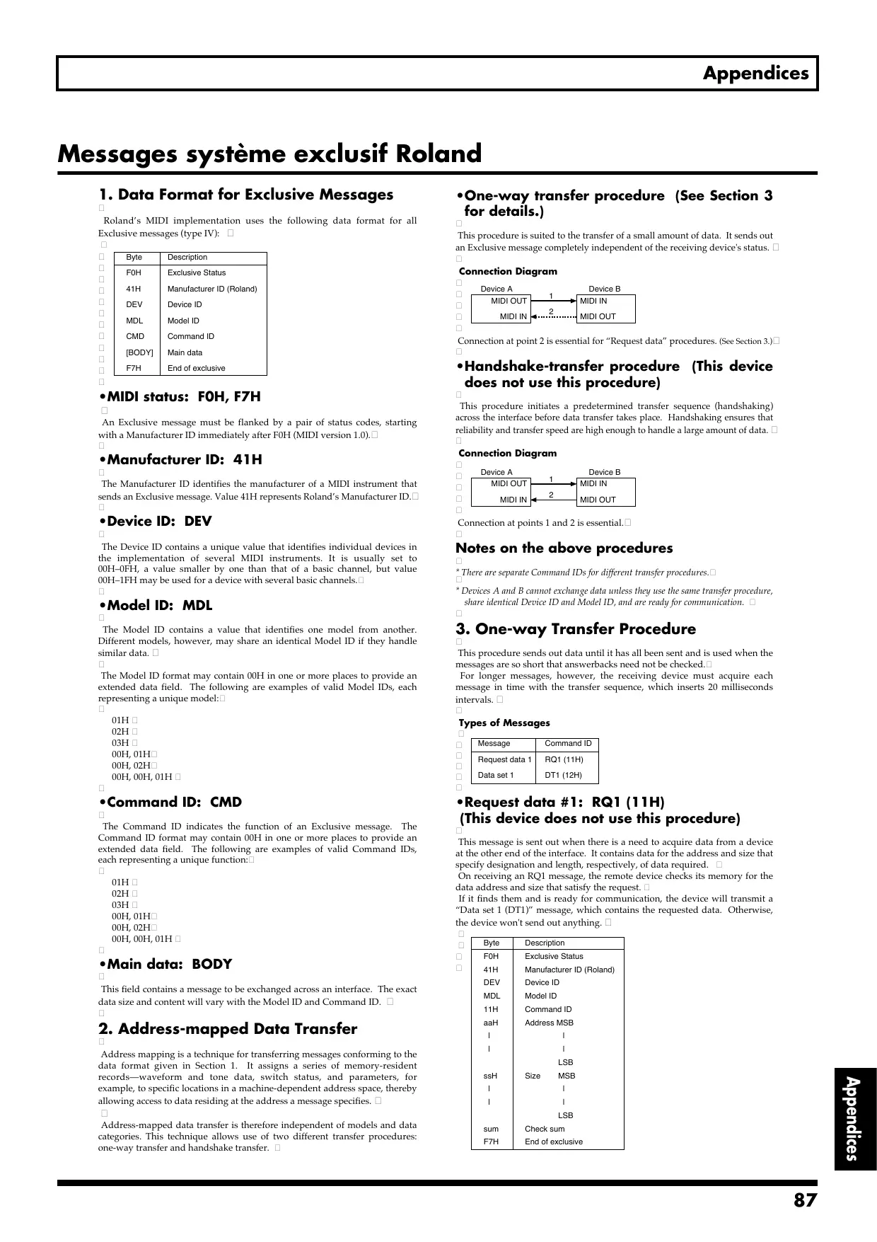
One-way transfer procedure (See Section 3 for details.)
This procedure is suited to the transfer of a small amount of data. It sends out an Exclusive message completely independent of the receiving device's status.
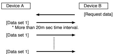
Connection Diagram
Connection at point 2 is essential for "Request data" procedures. (See Section 3.)
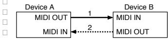
- Handshake-transfer procedure (This device does not use this procedure)
This procedure initiates a predetermined transfer sequence (handshaking) across the interface before data transfer takes place. Handshaking ensures that reliability and transfer speed are high enough to handle a large amount of data.
Connection Diagram
Connection at points 1 and 2 is essential.
Notes on the above procedures
- There are separate Command IDs for different transfer procedures.
- Devices A and B cannot exchange data unless they use the same transfer procedure, share identical Device ID and Model ID, and are ready for communication.
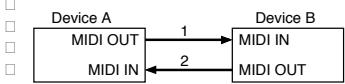
3. One-way Transfer Procedure
This procedure sends out data until it has all been sent and is used when the messages are so short that answerbacks need not be checked.
For longer messages, however, the receiving device must acquire each message in time with the transfer sequence, which inserts 20 milliseconds intervals.
Types of Messages
| Message | Command ID |
| Request data 1 | RQ1 (11H) |
| Data set 1 | DT1 (12H) |
- Request data #1: RQ1 (11H) (This device does not use this procedure)
This message is sent out when there is a need to acquire data from a device at the other end of the interface. It contains data for the address and size that specify designation and length, respectively, of data required.
On receiving an RQ1 message, the remote device checks its memory for the data address and size that satisfy the request.
If it finds them and is ready for communication, the device will transmit a "Data set 1 (DT1)" message, which contains the requested data. Otherwise, the device won't send out anything.
| Byte | Description |
| F0H | Exclusive Status |
| 41H | Manufacturer ID (Roland) |
| DEV | Device ID |
| MDL | Model ID |
| 11H | Command ID |
| aaH | Address MSB |
| I | I |
| I | I |
| LSB | |
| ssH | Size MSB |
| I | I |
| I | I |
| LSB | |
| sum | Check sum |
| F7H | End of exclusive |
- The size of the requested data does not indicate the number of bytes that will make up a DT1 message, but represents the address fields where the requested data resides.
- Some models are subject to limitations in data format used for a single transaction. Requested data, for example, may have a limit in length or must be divided into predetermined address fields before it is exchanged across the interface.
- The same number of bytes comprises address and size data, which, however, vary with the Model ID.
- The error-checking process uses a checksum that provides a bit pattern where the last 7 bits are zero when values for an address, size, and that checksum are summed.
- Data set 1: DT1 (12H)
This message corresponds to the actual data transfer process.
Because every byte in the data is assigned a unique address, a DT1 message can convey the starting address of one or more bits of data as well as a series of data formatted in an address-dependent order.
The MIDI standards inhibit non real-time messages from interrupting an Exclusive one. This fact is inconvenient for devices that support a "soft-thru" function. To maintain compatibility with such devices, Roland has limited the DT1 to 256 bytes so that an excessively long message is sent out in separate 'segments'.
| Byte | Description |
| F0H | Exclusive Status |
| 41H | Manufacturer ID (Roland) |
| DEV | Device ID |
| MDL | Model ID |
| 12H | Command ID |
| aaH | Address MSB |
| I | I |
| I | I |
| LSB | |
| ddH | Data MSB |
| I | I |
| I | I |
| LSB | |
| sum | Check sum |
| F7H | End of exclusive |
- A DT1 message is capable of providing only the valid data among those specified by an RQ1 message.
- Some models are subject to limitations in data format used for a single transaction. Requested data, for example, may have a limit in length or must be divided into predetermined address fields before it is exchanged across the interface.
- The number of bytes comprising address data varies from one Model ID to another.
- The error-checking process uses a checksum that provides a bit pattern where the last 7 bits are zero when values for an address, size, and that checksum are summed.
Example of Message Transactions
Device A sending data to Device B
Transfer of a DT1 message is all that takes place.
Device B requesting data from Device A
Device B sends an RQ1 message to Device A.
Checking the message, Device A sends a DT1 message back to Device B.
Implémentation MIDI
Model: GS-10
Date: Jul. 15, 2003
Version: 1.00
1. RECOGNIZED RECEIVE DATA
CHANNEL VOICEMESSAGE
Control Change
Status Second Third BnH ccH vvH
n = MIDI Channel Number: 0H - FH (ch.1 - ch.16)
cc = Controller Number: 00H, 20H (0, 32)
01H-1FH(1-31)
40H-5FH(64-95)
vv = Value: 00H-7FH(0-127)
- Control numbers 00H and 20H are recognized as Bank Select messages.
00H: For values of 01H or lower, the Program Change Map will be switched according to the value. For values of 02H or higher, the received data will be ignored.
20H: The received data will be ignored, regardless of the value.
- By specifying this as a Source for "Assign" (p. 60) you can use these messages to control a Target.
Program Change
Status Second
CnH ppH
n = MIDI Channel Number: 0H - FH (ch.1 - ch.16)
pp = Program Number: 00H - 7FH (No.1 - No.128)
- Patches will be selected according to the program number that is received.
- There are two Program Change Maps which are referenced when selecting programs, and these are switched by Bank Select messages.
SYSTEM REALTIMEMESSAGE
Timing Clock
Status
F8H
Active Sensing
Status
FEH
- When an Active Sensing message is received, the interval of all subsequent messages will begin to be monitored. If an interval greater than 400 msec. between messages, the display will indicate "MIDI Off Line!"
ii = Manufacturer ID: 41H (Roland)
dd ... ee = Data: 00H - 7FH (0 - 127)
F7H = EOX (End of Exclusive/System common)
- For more details, please refer to "Roland Exclusive Message."
2. TRANSMITTED DATA
CHANNEL VOICEMESSAGE
Control Change
Status Second Third
BnH ccH vvH
n = MIDI Channel Number: 0H - FH (ch.1 - ch.16)
cc = Controller Number: 00H, 20H (0, 32)
01H-1FH(1-31)
21H-5FH(33-95)
vv = Value: 00H-7FH(0-127)
- If you set up a system parameter "MIDI PC Out" for "On," Bank Select (00H, 20H) is transmitted when switching patch.
- If you set up a control change number at a system parameter "MIDI EXP Out," control change information is transmitted when operating an external EXP pedal.
- If you set up a control change number at a system parameter "MIDI CTL 1 Out," control change information is transmitted when operating an external CTL pedal.
- If you set up a control change number at a system parameter "MIDI CTL 2 Out," control change information is transmitted when operating an external CTL pedal.
Program Change
Status Second
CnH ppH
n = MIDI Channel Number: 0H - FH (ch.1 - ch.16)
pp = Program Number: 00H - 7FH (No.1 - No.128)
- If you set up a system parameter "MIDI PC Out" for "On," program change information is transmitted when switching patch.
SYSTEM REALTIMEMESSAGE
Start
Status
FAH
-Stop
Status
FCH
ii = Manufacturer ID: 41H (Roland)
dd ... ee = Data: 00H - 7FH (0 - 127)
F7H = EOX (End of Exclusive/System common)
- For more details, please refer to "Roland Exclusive Message."
MIDI Machine Control (MMC)
F0H 7FH 7FH 06H com F7H
F0H = System Exclusive
7FH = ID Number (Universal Realtime Message)
7FH = Device ID (Broadcast)
06H = Sub ID#1(Machine Control Command)
com = Sub ID#2(MMC Command)
F7H = EOX (End of Exclusive/System common)
- "com" (MMC Command) that I transmit with GS-10 is following.
01H Stop
02H Play
44H 06H 01H 00H 00H 00H 00H 00H RESET
06H REC
3. EXCLUSIVE COMMUNICATION
On the GS-10, exclusive messages can be used as follows. - Transmit/ receive GS-10 system/ patch data.
The model ID for GS-10 exclusive messages is 00H 63H, and you can set up the device ID at 00H-1FH.
ONEWAY COMMUNICATION
Request Data 1
RQ1(11H)
F0H 41H dev 00H 63H 11H aaH bbH ccH ddH ssH ttH uuH vvH sum F7H
FOH = Exclusive Status
41H = Manufacturer ID (Roland)
dev = Device ID (Dev=00H-1FH)
00H = Model ID MSB (GS-10)
63H = Model ID LSB (GS-10)
11H= Command ID (RQ1)
aaH = Address MSB
bbH = Address :
ccH = Address :
ddH= Address LSB
ssH = Size MSB
ttH = Size
uuH = Size
vvH = Size LSB
sum = Checksum
F7H = EOX (End of System Exclusive)
-
This message can only be received, and is not transmitted from the GS-10.
-
When transmitting large Size values spanning fragmented addresses, the data can be transmitted only to those addresses that are contiguous.
- Data Set 1
DT1(12H)
F0H 41H dev 00H 63H 12H aaH bbH ccH ddH eeH ... ffH sum F7H
FOH = Exclusive Status
41H = Manufacturer ID (Roland)
dev = Device ID (dev = 00H-1FH)
00H = Model ID MSB (GS-10)
63H = Model ID LSB (GS-10)
12H= Command ID (DT1)
aaH = Address MSB
bbH = Address :
ccH = Address :
ddH = Address LSB
eeH = Data
:=
ffH = Data
sum = Checksum
F7H = EOX (End of System Exclusive)
- When transmitting large amounts of data spanning fragmented addresses, the data can be transmitted only to those addresses that are contiguous.
Inquiry Message
Identity Request
F0H 7EH 10H 06H 01H F7H
FOH = Exclusive Status
7EH = ID Number
10H = Device ID
06H = Sub ID#1
01H = Sub ID#2
F7H = EOX (End of System Exclusive)
- The 7FH (Broadcast) device ID is also supported.
- When an Identity Request is received, the GS-10 will transmitted the following Identity Reply.
Identity Reply
F0H 7EH 10H 06H 02H 41H 63H 01H 00H 00H 00H 00H 00H F7H
FOH = Exclusive Status
7EH= ID Number (Universal Non-realtime Message)
10H= Device ID
06H= Sub ID#1
02H= Sub ID#2
41H= ID Number (Roland)
63H 01H= Device Family Code
00H 00H= Device Family Number Code
00H 00H 00H 00H = Software Revision Level
F7H= EOX (End of System Exclusive)
- When an Identity Request is received, the GS-10 will transmitted the following Identity Reply.
4. PARAMETER ADDRESS MAP
The address and size are displayed under 7-bit hexadecimal notation.
Address MSB LSB
Binary 0aaa aaaa 0bbb bbbb 0ccc ccccc 0ddd dddd
7-bitHexadecimal AA BB CC DD
Size MSB
Binary 0sss ssss 0tt ttt 0uuu uuuu 0vvv vvvv
7-bitHexadecimal SS TT UU VV
Address Block Map
| Address | Block | Sub Block | Note |
| 00 00 00 00 | SYSTEM | TUNER | ... Individual |
| OUTPUT | *Refer to "Table TUNER" | ||
| DIRECT PATCH | ... Individual | ||
| 01 01 00 00 | MIDI | *Refer to "Table OUTPUT" | |
| 01 02 00 00 | MIC | ... Individual | |
| 01 03 00 00 | SYSTEM | *Refer to "Table MIC" | |
| 01 04 00 00 | MIDI | *Refer to "Table SYSTEM" | |
| 01 05 00 00 | METER | *Refer to "Table MIDI" | |
| 02 00 00 00 | USB Setting | ... Individual | |
| 03 00 00 00 | HARMONIST User Scale | *Refer to "Table USB Setting" | |
| 03 01 00 00 | AUTO RIFF User Phrase | *Refer to "Table HARMONIST" | |
| 03 02 00 00 | AMP Customize | *Refer to "Table AUTO RIFF" | |
| 03 03 00 00 | SPEAKER Customize | *Refer to "Table AMP" | |
| 03 04 00 00 | OD/DS Customize | *Refer to "Table SPEAKER" | |
| 03 05 00 00 | WAH Customize | ... Individual | |
| 04 00 00 00 | Quick Fx | ROM Area (Data) | ... Read Only, Individual |
| 05 00 00 00 | ROM Area (Name) | *Refer to "Table Quick Fx Data" | |
| 06 00 00 00 | User Patch | Patch 001 | ... Read Only, Individual |
| 06 01 00 00 | Patch 002 | *Refer to "Table Patch" | |
| : | : | ||
| 06 62 00 00 | Patch 099 | ||
| 06 63 00 00 | Patch 100 | ||
| 07 00 00 00 | ROM Patch | Patch 101 | ... Read Only, Individual |
| 07 01 00 00 | Patch 102 | *Refer to "Table Patch" | |
| : | : | ||
| 07 62 00 00 | Patch 199 | ||
| 07 63 00 00 | Patch 200 | ||
| 08 00 00 00 | Temporary Buffer | ... Bulk | |
| 09 00 00 00 | Temporary Buffer | *Refer to "Table Patch" | |
| 0A 00 00 00 | Patch Change | ... Individual | |
| 0A 01 00 00 | Patch Write | *Refer to "Table Patch Change" | |
| 0A 02 00 00 | Current Patch | ... Individual | |
| 0A 03 00 00 | Patch Initialize | *Refer to "Table Patch" | |
| 0A 04 00 00 | AMP Ch Copy | *Refer to "Table Patch Initialize" | |
| 0B 00 00 00 | Quick Fx Number | *Refer to "Table AMP Ch Copy" | |
| 0B 01 00 00 | Quick Fx Count | *Refer to "Table Quick Fx Number" | |
| 0C 00 00 00 | TUNER/METER Mode | *Refer to "Table Quick Fx Count" | |
| Patch Change | When transmitted: Transmits the patch number. | DATA: Patch Number | |
| When received: Changes the Patch. | DATA: Patch Number | ||
| Data size is fixed at 2 bytes. | |||
| Upon receiving RQ1, the GS-10 replies with the patch number. | |||
| Request size to the GS-10 at this time is fixed at 2 bytes (set at 00 00 00 02). | |||
| Patch Write | When received: After the patch is written, the patch is switched to the received patch number, and the Current Patch is output. | ||
| Current Patch | When received: Current patch number is transmitted (only when RQ1 is received). | ||
| Patch | When transmitted: DATA: 01H is transmitted. | ||
| Initialize | When received: Initial value is set if DATA: 01H is received. | ||
| Data size is fixed at 1 byte. | |||
| AMP Ch Copy | When transmitted: Copy-destination amp channel is transmitted. | ||
| When received: Copy-destination amp channel is received. | |||
| Data size is fixed at 1 byte. | |||
| Quick Fx Number | When transmitted: Quick Fx number is transmitted. | DATA: Quick Fx Number | |
| When received: Quick Fx number is changed. | DATA: Quick Fx Number | ||
| Data size is fixed at 1 byte. | |||
| Quick Fx Count | Number of Quick Fx in each Effect block. | ||
| Request size is fixed at 1 byte (set at 00 00 00 01). | |||
| TUNER/METER | Mode 01H: TUNER Mode | ||
| 02H: METER Mode | |||
| 00H: exit (Play Mode) | |||
| * In TUNER mode: Pitch, Note data transmitted. | |||
| * In METER mode: METER POINT data transmitted. | |||
| During TAP operations: Delay Time, Delay Time (Fine) transmitted (when setting BPM: Master BPM transmitted). | |||
- The GS-10 can use two methods of communication; Individual Parameter and Bulk Dump.
- Bulk data can be received when the Bulk Load Ready function is accessed in "MIDI:Bulk Load" screen (System mode).
- Although individual data can be received at any time, be sure to appropriately describe the value for one parameter in one packet [F0...F7].
- Do not use an address appended with "#" as the first address.
- Do not specify an odd-number address for Quick Fx Data, SYSTEM:MIDI Program Map.
- Parameters for which Size is 2 or higher should not be separated; make sure these are sent in the same packet.
- Parameters with Size of 2 or higher transmitted from the specified addresses in sequence, from MSB to LSB.
- Output of Quick Fx Name and EFFECT CHAIN is fixed as 12 bytes.
Table TUNER
| Address(H) | Size(H) | Data(H) | Parameter | Description |
| 00 00 00 00 | 00 00 00 01 | 00 - 0A | TUNER Pitch | 00 : 435Hz01 : 436Hz:0A : 445Hz |
| 00 00 00 01 | 00 00 00 01 | 00 - 01 | TUNER Out | 00 : Mute01 : Bypass |
Table OUTPUT
| Address(H) | Size(H) | Data(H) | Parameter | Description |
| 01 00 00 00 | 00 00 00 01 | 00 - 04 | OUTPUT Select | 00 : LINE/PHONES |
| 01 : COMBO AMP | ||||
| 02 : STACK AMP | ||||
| 03 : COMBO Return | ||||
| 04 : STACK Return |
Table DIRECT PATCH
| Address(H) | Size(H) | Data(H) | Parameter | Description | |||||
| 01 | 01 | 00 | 00 | 00 | 00 | 00 | - 01 47 | Direct Patch 1 | 00 00 : U001(User) |
| : | |||||||||
| 00 63 : U100(User) | |||||||||
| 00 64 : P101(Preset) | |||||||||
| : | |||||||||
| 00 7F : P128(Preset) | |||||||||
| 01 00 : P129(Preset) | |||||||||
| : | |||||||||
| 01 47 : P200(Preset) | |||||||||
| 01 | 01 | 00 | 02 | 00 | 00 | 00 | - 01 47 | Direct Patch 2 | 00 00 : U001(User) |
| 01 | 01 | 00 | 03# | : | |||||
| 00 63 : U100(User) | |||||||||
| 00 64 : P101(Preset) | |||||||||
| : | |||||||||
| 00 7F : P128(Preset) | |||||||||
| 01 00 | 01 00 : P129(Preset) | ||||||||
| : | |||||||||
| 01 47 : P200(Preset) | |||||||||
| 01 | 01 | 00 | 04 | 00 | 00 | 00 | - 01 47 | Direct Patch 3 | 00 00 : U001(User) |
| 01 | 01 | 00 | 05# | : | |||||
| 00 63 : U100(User) | |||||||||
| 00 64 : P101(Preset) | |||||||||
| : | |||||||||
| 00 7F : P128(Preset) | |||||||||
| 01 00 | 01 00 : P129(Preset) | ||||||||
| : | |||||||||
| 01 47 : P200(Preset) | |||||||||
| 01 | 01 | 00 | 06 | 00 | 00 | 00 | - 01 47 | Direct Patch 4 | 00 00 : U001(User) |
| 01 | 01 | 00 | 07# | : | |||||
| 00 63 : U100(User) | |||||||||
| 00 64 : P101(Preset) | |||||||||
| : | |||||||||
| 00 7F : P128(Preset) | |||||||||
| 01 00 : P129(Preset) | |||||||||
| : | |||||||||
| 01 47 : P200(Preset) | |||||||||
Table MIC
| Address(H) | Size(H) | Data(H) | Parameter | Description |
| 01 02 00 00 | 00 00 00 01 | 00 - 0A | Mic Gain | 00 : 001 : 1002 : 20:0A : 100 |
Table SYSTEM
| Address(H) | Size(H) | Data(H) | Parameter | Description |
| 01 03 00 00 | 00 00 00 01 | 00 - 0F | LCD Contrast | 1 - 16 |
| 01 03 00 01 | 00 00 00 01 | 00 - 01 | Speaker Output | 00 : OFF |
| 01 : ON | ||||
| 01 03 00 02 | 00 00 00 02 | 00 00 - 01 47 | Patch Extent | 00 00 : 001(User) |
| 00 63 : 100(User) | ||||
| 00 64 : 101(Preset) | ||||
| 00 7F : 128(Preset) | ||||
| 01 00 : 129(Preset) | ||||
| 01 47 : 200(Preset) | ||||
| 01 03 00 04 | 00 00 00 01 | 00 - 01 | Assign Hold | 00 : OFF |
| 01 : ON | ||||
| 01 03 00 05 | 00 00 00 01 | 00 - 01 | Knob Mode | 00 : Immediate |
| 01 : Current Setting | ||||
| 01 03 00 06 | 00 00 00 01 | 00 - 05 | Exp Pedal Function | 00 : Auto |
| 01 : Assign1-8 | ||||
| 02 : Foot Volume | ||||
| 03 : Patch Level | ||||
| 04 : Pedal Wah | ||||
| 05 : Pedal Bend | ||||
| 01 03 00 07 | 00 00 00 01 | 00 - 0A | CTL1 Function | 00 : Assign1-8 |
| 01 : TUNER On/Off | ||||
| 02 : Remote Start/Stop | ||||
| 03 : Direct Patch Up | ||||
| 04 : Direct Patch Down | ||||
| 05 : Patch Up | ||||
| 06 : Patch Down | ||||
| 07 : Patch Level Inc1 | ||||
| 08 : Patch Level Inc2 | ||||
| 09 : Patch Level Dec1 | ||||
| 0A : Patch Level Dec2 | ||||
| 01 03 00 08 | 00 00 00 01 | 00 - 0A | CTL2 Function | 00 : Assign1-8 |
| 01 : TUNER On/Off | ||||
| 02 : Remote Start/Stop | ||||
| 03 : Direct Patch Up | ||||
| 04 : Direct Patch Down | ||||
| 05 : Patch Up | ||||
| 06 : Patch Down | ||||
| 07 :patch Level Inc1 | ||||
| 08 : Patch Level Inc2 | ||||
| 09 : Patch Level Dec1 | ||||
| 0A : Patch Level Dec2 |
Table MIDI
| Address(H) | Size(H) | Data(H) | Parameter | Description | |||||
| 01 | 04 | 00 | 00 | 00 | 00 | 01 | 00 - 0F | MIDI Rx Channel | 00 : 1 |
| OF : 16 | |||||||||
| 01 | 04 | 00 | 01 | 00 | 00 | 01 | 00 - 01 | MIDI Omni Mode | 00 : Omni Off |
| 01 : Omni On | |||||||||
| 01 | 04 | 00 | 02 | 00 | 00 | 01 | 00 - 10 | MIDI Tx Channel | 00 : 1 |
| OF : 16 | |||||||||
| 10 : Rx | |||||||||
| 01 | 04 | 00 | 03 | 00 | 00 | 01 | 00 - 1F | MIDI Device ID | 1 - 32 |
| 01 | 04 | 00 | 04 | 00 | 00 | 01 | 00 - 01 | MIDI Sync Clock | 00 : Auto |
| 01 : Internal | |||||||||
| 01 | 04 | 00 | 05 | 00 | 00 | 01 | 00 - 02 | MIDI Remote Control | 00 : Standard |
| 01 : Advanced | |||||||||
| 02 : MMC | |||||||||
| 01 | 04 | 00 | 06 | 00 | 00 | 01 | 00 - 01 | MIDI Knob Control Out | 00 : Off |
| 01 : On | |||||||||
| 01 | 04 | 00 | 07 | 00 | 00 | 01 | 00 - 01 | MIDI PC Out | 00 : Off |
| 01 : On | |||||||||
| 01 | 04 | 00 | 08 | 00 | 00 | 01 | 00 - 5E | MIDI EXP Out | 00 : Off |
| 01 : 1 | |||||||||
| 1F : 31 | |||||||||
| 20 : 33 | |||||||||
| 5E : 95 | |||||||||
| 01 | 04 | 00 | 09 | 00 | 00 | 01 | 00 - 5E | MIDI CTL1 Out | 00 : Off |
| 01 : 1 | |||||||||
| 1F : 31 | |||||||||
| 20 : 33 | |||||||||
| 5E : 95 | |||||||||
| 01 | 04 | 00 | 0A | 00 | 00 | 01 | 00 - 5E | MIDI CTL2 Out | 00 : Off |
| 01 : 1 | |||||||||
| 1F : 31 | |||||||||
| 20 : 33 | |||||||||
| 5E : 95 | |||||||||
| 01 | 04 | 00 | 0B | 00 | 00 | 01 | 00 - 01 | MIDI Map Select | 00 : Fix |
| 01 : Program | |||||||||
| --- | MIDI | Program | Map --- | ||||||
| 01 | 04 | 10 | 00 | 00 | 00 | 02 | 00 00 | MIDI Program Map | MIDI Map Select = Program |
| 01 | 04 | 10 | 01# | - 01 47 | B#0 P#1 | 00 00 : U001(User) | |||
| : | |||||||||
| 00 63 : U100(User) | |||||||||
| 00 64 : P101(Preset) | |||||||||
| : | |||||||||
| 00 7F : P128(Preset) | |||||||||
| 01 00 : P129(Preset) | |||||||||
| : | |||||||||
| 01 47 : P200(Preset) | |||||||||
| 01 | 04 | 10 | 02 | 00 | 00 | 02 | 00 00 | MIDI Program Map | MIDI Program Select = Program |
| 01 | 04 | 10 | 03# | - 01 47 | B#0 P#2 | ||||
| 01 | 04 | 11 | 7E | 00 | 00 | 02 | 00 00 | MIDI Program Map | MIDI Program Select = Program |
| 01 | 04 | 11 | 7F# | - 01 47 | B#0 P#128 | ||||
| 01 | 04 | 12 | 00 | 00 | 00 | 02 | 00 00 | MIDI Program Map | MIDI Program Select = Program |
| 01 | 04 | 12 | 01# | - 01 47 | B#1 P#1 | ||||
| : | |||||||||
| 01 | 04 | 13 | 7E | 00 | 00 | 02 | 00 00 | MIDI Program Map | MIDI Program Select = Program |
| 01 | 04 | 13 | 7F# | - 01 47 | B#1 P#128 | ||||
Table METER
| Address(H) | Size(H) | Data(H) | Parameter | Description |
| 01 05 00 00 | 00 00 00 01 | 00 - 0D | METER Point | Input, Effects, USB, Output *Refer to "Table METER Point" |
Table USB Setting
| Address(H) | Size(H) | Data(H) | Parameter | Description | ||||||
| 02 | 00 | 00 | 00 | 00 | 00 | 00 | 01 | 00 - 64 | USB/Digital Out | 00 : 001 : 264 : 200 |
| 02 | 00 | 00 | 01 | 00 | 00 | 00 | 01 | 00 - 64 | Input Level | 0 - 100 |
| 02 | 00 | 00 | 02 | 00 | 00 | 00 | 01 | 00 - 01 | Direct Monitor | 00 : Off01 : On |
| 02 | 00 | 00 | 03 | 00 | 00 | 00 | 01 | 00 - 01 | Output Mode | 00 : Stereo(L/R)01 : Effect/Direct |
| 02 | 00 | 00 | 04 | 00 | 00 | 00 | 01 | 00 - 01 | Driver Mode | 00 : Standard01 : Advanced |
| 02 | 00 | 00 | 05 | 00 | 00 | 00 | 01 | 00 - 01 | Std.Drv Func | 00 : Audio01 : Audio & MIDI |
| 02 | 00 | 00 | 06 | 00 | 00 | 00 | 01 | 00 - 01 | Monitor Cmd | 00 : Disable01 : Enable |
Table HARMONIST
| Address(H) | Size(H) | Data(H) | Parameter | Description |
| --- Scale 1 --- | ||||
| 03 00 00 00 | 00 00 00 01 | 00 - 30 | Scale 1 C | *Refer to "Table HR Harmony Note" |
| 03 00 00 01 | 00 00 00 01 | 00 - 30 | Scale 1 Db | |
| 03 00 00 02 | 00 00 00 01 | 00 - 30 | Scale 1 D | |
| 03 00 00 03 | 00 00 00 01 | 00 - 30 | Scale 1 Eb | |
| 03 00 00 04 | 00 00 00 01 | 00 - 30 | Scale 1 E | |
| 03 00 00 05 | 00 00 00 01 | 00 - 30 | Scale 1 F | |
| 03 00 00 06 | 00 00 00 01 | 00 - 30 | Scale 1 F# | |
| 03 00 00 07 | 00 00 00 01 | 00 - 30 | Scale 1 G | |
| 03 00 00 08 | 00 00 00 01 | 00 - 30 | Scale 1 Ab | |
| 03 00 00 09 | 00 00 00 01 | 00 - 30 | Scale 1 A | |
| 03 00 00 0A | 00 00 00 01 | 00 - 30 | Scale 1 Bb | |
| 03 00 00 0B | 00 00 00 01 | 00 - 30 | Scale 1 B | |
| --- Scale 2 --- | ||||
| 03 00 01 00 | 00 00 00 01 | 00 - 30 | Scale 2 C | *Refer to "Table HR Harmony Note" |
| 03 00 01 01 | 00 00 00 01 | 00 - 30 | Scale 2 Db | |
| 03 00 01 02 | 00 00 00 01 | 00 - 30 | Scale 2 D | |
| 03 00 01 03 | 00 00 00 01 | 00 - 30 | Scale 2 Eb | |
| 03 00 01 04 | 00 00 00 01 | 00 - 30 | Scale 2 E | |
| 03 00 01 05 | 00 00 00 01 | 00 - 30 | Scale 2 F | |
| 03 00 01 06 | 00 00 00 01 | 00 - 30 | Scale 2 F# | |
| 03 00 01 07 | 00 00 00 01 | 00 - 30 | Scale 2 G | |
| 03 00 01 08 | 00 00 00 01 | 00 - 30 | Scale 2 Ab | |
| 03 00 01 09 | 00 00 00 01 | 00 - 30 | Scale 2 A | |
| 03 00 01 0A | 00 00 00 01 | 00 - 30 | Scale 2 Bb | |
| 03 00 01 0B | 00 00 00 01 | 00 - 30 | Scale 2 B | |
| --- Scale 3 --- | ||||
| 03 00 02 00 | 00 00 00 01 | 00 - 30 | Scale 3 C | *Refer to "Table HR Harmony Note" |
| 03 00 02 01 | 00 00 00 01 | 00 - 30 | Scale 3 Db | |
| 03 00 02 02 | 00 00 00 01 | 00 - 30 | Scale 3 D | |
| 03 00 02 03 | 00 00 00 01 | 00 - 30 | Scale 3 Eb | |
| 03 00 02 04 | 00 00 00 01 | 00 - 30 | Scale 3 E | |
| 03 00 02 05 | 00 00 00 01 | 00 - 30 | Scale 3 F | |
| 03 00 02 06 | 00 00 00 01 | 00 - 30 | Scale 3 F# | |
| 03 00 02 07 | 00 00 00 01 | 00 - 30 | Scale 3 G | |
| 03 00 02 08 | 00 00 00 01 | 00 - 30 | Scale 3 Ab | |
| 03 00 02 09 | 00 00 00 01 | 00 - 30 | Scale 3 A | |
| 03 00 02 10 | 00 00 00 01 | 00 - 30 | Scale 3 Bb | |
| 03 00 02 11 | 00 00 00 01 | 00 - 30 | Scale 3 B | |
| --- Scale 4 --- | ||||
| 03 00 03 00 | 00 00 00 01 | 00 - 30 | Scale 4 C | *Refer to "Table HR Harmony Note" |
| 03 00 03 01 | 00 00 00 01 | 00 - 30 | Scale 4 Db | |
| 03 00 03 02 | 00 00 00 01 | 00 - 30 | Scale 4 D | |
| 03 00 03 03 | 00 00 00 01 | 00 - 30 | Scale 4 Eb | |
| 03 00 03 04 | 00 00 00 01 | 00 - 30 | Scale 4 E | |
| 03 00 03 05 | 00 00 00 01 | 00 - 30 | Scale 4 F | |
| 03 00 03 06 | 00 00 00 01 | 00 - 30 | Scale 4 F# | |
| 03 00 03 07 | 00 00 00 01 | 00 - 30 | Scale 4 G | |
| 03 00 03 08 | 00 00 00 01 | 00 - 30 | Scale 4 Ab | |
| 03 00 03 09 | 00 00 00 01 | 00 - 30 | Scale 4 A | |
| 03 00 03 10 | 00 00 00 01 | 00 - 30 | Scale 4 Bb | |
| 03 00 03 11 | 00 00 00 01 | 00 - 30 | Scale 4 B | |
| --- Scale 5 --- | ||||
| 03 00 04 00 | 00 00 00 01 | 00 - 30 | Scale 5 C | *Refer to "Table HR Harmony Note" |
| 03 00 04 01 | 00 00 00 01 | 00 - 30 | Scale 5 Db | |
| 03 00 04 02 | 00 00 00 01 | 00 - 30 | Scale 5 D | |
| 03 00 04 03 | 00 00 00 01 | 00 - 30 | Scale 5 Eb | |
| 03 00 04 04 | 00 00 00 01 | 00 - 30 | Scale 5 E | |
| 03 00 04 05 | 00 00 00 01 | 00 - 30 | Scale 5 F | |
| 03 00 04 06 | 00 00 00 01 | 00 - 30 | Scale 5 F# | |
| 03 00 04 07 | 00 00 00 01 | 00 - 30 | Scale 5 G | |
| 03 00 04 08 | 00 00 00 01 | 00 - 30 | Scale 5 Ab | |
| 03 00 04 09 | 00 00 00 01 | 00 - 30 | Scale 5 A | |
| 03 00 04 10 | 00 00 00 01 | 00 - 30 | Scale 5 Bb | |
| 03 00 04 11 | 00 00 00 01 | 00 - 30 | Scale 5 B | |
| --- Scale 6 --- | ||||
| 03 00 05 00 | 00 00 00 01 | 00 - 30 | Scale 6 C | *Refer to "Table HR Harmony Note" |
| 03 00 05 01 | 00 00 00 01 | 00 - 30 | Scale 6 Db | |
| 03 00 05 02 | 00 00 00 01 | 00 - 30 | Scale 6 D | |
| 03 00 05 03 | 00 00 00 01 | 00 - 30 | Scale 6 Eb | |
| 03 00 05 04 | 00 00 00 01 | 00 - 30 | Scale 6 E | |
| 03 00 05 05 | 00 00 00 01 | 00 - 30 | Scale 6 F | |
| 03 00 05 06 | 00 00 00 01 | 00 - 30 | Scale 6 F# | |
| 03 00 05 07 | 00 00 00 01 | 00 - 30 | Scale 6 G | |
| 03 00 05 08 | 00 00 00 01 | 00 - 30 | Scale 6 A | |
| 03 00 05 09 | 00 00 00 01 | 00 - 30 | Scale 6 A | |
| 03 00 05 10 | 00 00 00 01 | 00 - 30 | Scale 6 Bb | |
| 03 00 05 11 | 00 00 00 01 | 00 - 30 | Scale 6 B | |
| --- Scale 7 --- | ||||
| 03 00 06 00 | 00 00 00 01 | 00 - 30 | Scale 7 C | *Refer to "Table HR Harmony Note" |
| 03 00 06 01 | 00 00 00 01 | 00 - 30 | Scale 7 Db | |
| 03 00 06 02 | 00 00 00 01 | 00 - 30 | Scale 7 D | |
| 03 00 06 03 | 00 00 00 01 | 00 - 30 | Scale 7 Eb | |
| 03 00 06 04 | 00 00 00 01 | 00 - 30 | Scale 7 F | |
| 03 00 06 05 | 00 00 00 01 | 00 - 30 | Scale 7 F | |
| 03 00 06 06 | 00 00 00 01 | 00 - 30 | Scale 7 F# | |
| 03 00 06 07 | 00 00 00 01 | 00 - 30 | Scale 7 G | |
| 03 00 06 08 | 00 00 00 01 | 00 - 30 | Scale 7 F | |
| 03 00 06 09 | 00 00 00 01 | 00 - 30 | Scale 7 A | |
| 03 00 06 11 | 00 00 00 01 | 00 - 30 | Scale 7 Bb | |
| 03 00 06 12 | 00 00 00 01 | 00 - 30 | Scale 7 B | |
| --- Scale 8 --- | ||||
| 03 00 07 01 | 00 00 00 01 | 00 - 30 | Scale 8 C | *Refer to "Table HR Harmony Note" |
| 03 00 07 02 | 00 00 00 01 | 00 - 30 | Scale 8 D | |
| 03 00 07 03 | 00 00 00 01 | 00 - 30 | Scale 8 Eb | |
| 03 00 07 04 | 00 00 00 01 | 00 - 30 | Scale 8 F | |
| 03 00 07 05 | 00 00 00 01 | 00 - 30 | Scale 8 G | |
| 03 00 07 06 | 00 00 00 01 | 00 - 30 | Scale 8 F | |
| 03 00 07 07 | 00 00 00 01 | 00 - 30 | Scale 8 G | |
| 03 00 07 08 | 00 00 00 01 | 00 - 30 | Scale 8 A | |
| 03 00 07 09 | 00 00 00 01 | 00 - 30 | Scale 8 Bb | |
| 03 00 07 11 | 00 00 00 01 | 00 - 30 | Scale 8 B | |
| --- Scale 9 --- | |||||||
| 03 | 00 | 08 | 00 | 00 | 00 | 01 | 00 - 30 |
| 03 | 00 | 08 | 01 | 00 | 00 | 01 | 00 - 30 |
| 03 | 00 | 08 | 02 | 00 | 00 | 01 | 00 - 30 |
| 03 | 00 | 08 | 03 | 00 | 00 | 01 | 00 - 30 |
| 03 | 00 | 08 | 04 | 00 | 00 | 01 | 00 - 30 |
| 03 | 00 | 08 | 05 | 00 | 00 | 01 | 00 - 30 |
| 03 | 00 | 08 | 06 | 00 | 00 | 01 | 00 - 30 |
| 03 | 00 | 08 | 07 | 00 | 00 | 01 | 00 - 30 |
| 03 | 00 | 08 | 08 | 00 | 00 | 01 | 00 - 30 |
| 03 | 00 | 08 | 09 | 00 | 00 | 01 | 00 - 30 |
| 03 | 00 | 08 | 0A | 00 | 00 | 01 | 00 - 30 |
| 03 | 00 | 08 | 0B | 00 | 00 | 01 | 00 - 30 |
| --- Scale 10 --- | |||||||
| 03 | 00 | 09 | 00 | 00 | 00 | 01 | 00 - 30 |
| 03 | 00 | 09 | 01 | 00 | 00 | 01 | 00 - 30 |
| 03 | 00 | 09 | 02 | 00 | 00 | 01 | 00 - 30 |
| 03 | 00 | 09 | 03 | 00 | 00 | 01 | 00 - 30 |
| 03 | 00 | 09 | 04 | 00 | 00 | 01 | 00 - 30 |
| 03 | 00 | 09 | 05 | 00 | 00 | 01 | 00 - 30 |
| 03 | 00 | 09 | 06 | 00 | 00 | 01 | 00 - 30 |
| 03 | 00 | 09 | 07 | 00 | 00 | 01 | 00 - 30 |
| 03 | 00 | 09 | 08 | 00 | 00 | 01 | 00 - 30 |
| 03 | 00 | 09 | 09 | 00 | 00 | 01 | 00 - 30 |
| 03 | 00 | 09 | 0A | 00 | 00 | 01 | 00 - 30 |
| 03 | 00 | 09 | 0B | 00 | 00 | 01 | 00 - 30 |
| --- Scale 11 --- | |||||||
| 03 | 00 | 0A | 00 | 00 | 00 | 01 | 00 - 30 |
| 03 | 00 | 0A | 01 | 00 | 00 | 01 | 00 - 30 |
| 03 | 00 | 0A | 02 | 00 | 00 | 01 | 00 - 30 |
| 03 | 00 | 0A | 03 | 00 | 00 | 01 | 00 - 30 |
| 03 | 00 | 0A | 04 | 00 | 00 | 01 | 00 - 30 |
| 03 | 00 | 0A | 05 | 00 | 00 | 01 | 00 - 30 |
| 03 | 00 | 0A | 06 | 00 | 00 | 01 | 00 - 30 |
| 03 | 00 | 0A | 07 | 00 | 00 | 01 | 00 - 30 |
| 03 | 00 | 0A | 08 | 00 | 00 | 01 | 00 - 30 |
| 03 | 00 | 0A | 09 | 00 | 00 | 01 | 00 - 30 |
| 03 | 00 | 0A | 1A | 00 | 00 | 01 | 00 - 30 |
| 03 | 00 | 0A | OB | 00 | 00 | 01 | 00 - 30 |
| --- Scale 12 --- | |||||||
| 03 | 00 | OB | 00 | 00 | 00 | 01 | 00 - 30 |
| 03 | 00 | OB | 01 | 00 | 00 | 01 | 00 - 30 |
| 03 | 00 | OB | 02 | 00 | 00 | 01 | 00 - 30 |
| 03 | 00 | OB | 03 | 00 | 00 | 01 | 00 - 30 |
| 03 | 00 | OB | 04 | 00 | 00 | 01 | 00 - 30 |
| 03 | 00 | OB | 05 | 00 | 00 | 01 | 00 - 30 |
| 03 | 00 | OB | 06 | 00 | 00 | 01 | 00 - 30 |
| 03 | 00 | OB | 07 | 00 | 00 | 01 | 00 - 30 |
| 03 | 00 | OB | 08 | 00 | 00 | 01 | 00 - 30 |
| 03 | 00 | OB | 09 | 00 | 00 | 01 | 00 - 30 |
| 03 | 00 | OB | 1A | 00 | 00 | 01 | 00 - 30 |
| 03 | 00 | OB | OB | 00 | 00 | 01 | 00 - 30 |
| --- Scale 14 --- | |||||||
| 03 | 00 | OC | 00 | 00 | 00 | 01 | 00 - 30 |
| 03 | 00 | OC | 01 | 00 | 00 | 01 | 00 - 30 |
| 03 | 00 | OC | 02 | 00 | 00 | 01 | 00 - 30 |
| 03 | 00 | OC | 03 | 00 | 00 | 01 | 00 - 30 |
| 03 | 00 | OC | 04 | 00 | 00 | 01 | 00 - 30 |
| 03 | 00 | OC | 05 | 00 | 00 | 01 | 00 - 30 |
| 03 | 00 | OC | 06 | 00 | 00 | 01 | 00 - 30 |
| 03 | 00 | OC | 07 | 00 | 00 | 01 | 00 - 30 |
| 03 | 00 | OC | OB | 00 | 00 | 01 | 00 - 30 |
| 03 | 00 | OC | OB | 00 | 00 | 01 | 00 - 30 |
| --- Scale 15 --- | |||||||
| 03 | 00 | OE | 00 | 00 | 00 | 01 | 00 - 30 |
| 03 | 00 | OE | 01 | 00 | 00 | 01 | 00 - 30 |
| 03 | 00 | OE | 02 | 00 | 00 | 01 | 00 - 30 |
| 03 | 00 | OE | 03 | 00 | 00 | 01 | 00 - 30 |
| 03 | 00 | OE | 04 | 00 | 00 | 01 | 00 - 30 |
| 03 | 00 | OE | 05 | 00 | 00 | 01 | 00 - 30 |
| 03 | 00 | OE | OB | 00 | 00 | 01 | 00 - 30 |
| 03 | 00 | OE | OB | 01 | 00 | 01 | 00 - 30 |
| --- Scale 16 --- | |||||||
| 03 | 00 | OF | 00 | 00 | 00 | 01 | 00 - 30 |
| 03 | 00 | OF | 01 | 00 | 00 | 01 | 00 - 30 |
| 03 | 00 | OF | 02 | 00 | 00 | 01 | 00 - 30 |
| 03 | 00 | OF | 03 | 00 | 00 | 01 | 00 - 30 |
| 03 | 00 | OF | 04 | 00 | 00 | 01 | 00 - 30 |
| 03 | 00 | OF | OB | 00 | 00 | 01 | 00 - 30 |
| 03 | 00 | OF | OB | 1A | 00 | 01 | 00 - 30 |
| 03 | 00 | OF | OB | 1A | 1A | 1A | 1A - 30 |
| --- Scale 17 --- | |||||||
| 03 | 00 | 10 | 00 | 00 | 00 | 01 | 00 - 30 |
| 03 | 00 | 10 | 11 | 00 | 00 | 01 | 00 - 30 |
| 03 | 00 | 10 | 12 | 00 | 00 | 01 | 00 - 30 |
| 03 | 00 | 10 | 13 | 00 | 00 | 01 | 00 - 30 |
| 03 | 00 | 11 | 14 | 11 | 11 | 11 | 11 - 30 |
| 03 | 11 | 12 | 13 | 11 | 11 | 11 | 11 - 30 |
| Scale 9 C |
| Scale 9 Db |
| Scale 9 D |
| Scale 9 E b |
| Scale 9 E F |
| Scale 9 F# |
| Scale 9 G |
| Scale 9 Ab |
| Scale 9 A |
| Scale 9 Bb |
| Scale 9 B |
| Scale 10 C |
| Scale 10 Db |
| Scale 10 D |
| Scale 10 Eb |
| Scale 10 E |
| Scale 10 F |
| Scale 10 F# |
| Scale 10 G |
| Scale 10 Ab |
| Scale 10 A |
| Scale 10 Bb |
| Scale 10 B |
| Scale 11 C |
| Scale 11 Db |
| Scale 11 D |
| Scale 11 Eb |
| Scale 11 E |
| Scale 11 F |
| Scale 11 F# |
| Scale 11 G |
| Scale 11 Ab |
| Scale 11 A |
| Scale 11 Bb |
| Scale 11 B |
| Scale 12 C |
| Scale 12 Db |
| Scale 12 D |
| Scale 12 Eb |
| Scale 12 E |
| Scale 12 F |
| Scale 12 F# |
| Scale 12 G |
| Scale 12 Ab |
| Scale 12 A |
| Scale 12 Bb |
| Scale 12 B |
| Scale 12 C |
| Scale 13 Db |
| Scale 13 D |
| Scale 13 Eb |
| Scale 13 E |
| Scale 13 F |
| Scale 13 F# |
| Scale 13 G |
| Scale 13 Ab |
| Scale 13 A |
| Scale 13 Bb |
| Scale 13 B |
| Scale 14 C |
| Scale 14 Db |
| Scale 14 D |
| Scale 14 Eb |
| Scale 14 E |
| Scale 14 F |
| Scale 14 F# |
| Scale 14 G |
| Scale 14 Ab |
| Scale 14 A |
| Scale 14 Bb |
| Scale 14 B |
| Scale 15 C |
| Scale 15 Db |
| Scale 15 D |
| Scale 15 Eb |
| Scale 15 E |
| Scale 15 F |
| Scale 15 F# |
| Scale 15 G |
| Scale 15 Ab |
| Scale 15 A |
| Scale 15 Bb |
| Scale 15 B |
| Scale 16 C |
| Scale 16 Db |
| Scale 16 D |
| Scale 16 Eb |
| Scale 16 E |
| Scale 16 F |
| Scale 16 F# |
| Scale 16 G |
| Scale 16 Ab |
| Scale 16 A |
| Scale 16 Bb |
| Scale 16 B |
| Scale 17 C |
| Scale 17 Db |
| Scale 17 D |
| Scale 17 Eb |
| Scale 17 E |
| Scale 17 F |
| Scale 17 F# |
| Scale 17 G |
| Scale 17 Ab |
| Scale 17 A |
| Scale 17 Bb |
| Scale 17 B |
*Refer to "Table HR Harmony Note"
*Refer to "Table HR Harmony Note"
*Refer to "Table HR Harmony Note"
*Refer to "Table HR Harmony Note"
*Refer to "Table HR Harmony Note"
*Refer to "Table HR Harmony Note"
*Refer to "Table HR Harmony Note"
*Refer to "Table HR Harmony Note"
*Refer to "Table HR Harmony Note"
| --- Scale 18 --- | ||||||
| 03 | 00 | 11 | 00 | 00 | 00 | 01 |
| 03 | 00 | 11 | 01 | 00 | 00 | 01 |
| 03 | 00 | 11 | 02 | 00 | 00 | 01 |
| 03 | 00 | 11 | 03 | 00 | 00 | 01 |
| 03 | 00 | 11 | 04 | 00 | 00 | 01 |
| 03 | 00 | 11 | 05 | 00 | 00 | 01 |
| 03 | 00 | 11 | 06 | 00 | 00 | 01 |
| 03 | 00 | 11 | 07 | 00 | 00 | 01 |
| 03 | 00 | 11 | 08 | 00 | 00 | 01 |
| 03 | 00 | 11 | 09 | 00 | 00 | 01 |
| 03 | 00 | 11 | 0A | 00 | 00 | 01 |
| 03 | 00 | 11 | 0B | 00 | 00 | 01 |
| --- Scale 19 --- | ||||||
| 03 | 00 | 12 | 00 | 00 | 00 | 01 |
| 03 | 00 | 12 | 01 | 00 | 00 | 01 |
| 03 | 00 | 12 | 02 | 00 | 00 | 01 |
| 03 | 00 | 12 | 03 | 00 | 00 | 01 |
| 03 | 00 | 12 | 04 | 00 | 00 | 01 |
| 03 | 00 | 12 | 05 | 00 | 00 | 01 |
| 03 | 00 | 12 | 06 | 00 | 00 | 01 |
| 03 | 00 | 12 | 07 | 00 | 00 | 01 |
| 03 | 00 | 12 | 08 | 00 | 00 | 01 |
| 03 | 00 | 12 | 09 | 00 | 00 | 01 |
| 03 | 00 | 12 | 0A | 00 | 00 | 01 |
| 03 | 00 | 12 | 0B | 00 | 00 | 01 |
| --- Scale 20 --- | ||||||
| 03 | 00 | 13 | 00 | 00 | 00 | 01 |
| 03 | 00 | 13 | 01 | 00 | 00 | 01 |
| 03 | 00 | 13 | 02 | 00 | 00 | 01 |
| 03 | 00 | 13 | 03 | 00 | 00 | 01 |
| 03 | 00 | 13 | 04 | 00 | 00 | 01 |
| 03 | 00 | 13 | 05 | 00 | 00 | 01 |
| 03 | 00 | 13 | 06 | 00 | 00 | 01 |
| 03 | 00 | 13 | 07 | 00 | 00 | 01 |
| 03 | 00 | 13 | 08 | 00 | 00 | 01 |
| 03 | 00 | 13 | 09 | 00 | 00 | 01 |
| 03 | 00 | 13 | 0A | 00 | 00 | 01 |
| 03 | 00 | 13 | 0B | 00 | 00 | 01 |
| --- Scale 21 --- | ||||||
| 03 | 00 | 14 | 00 | 00 | 00 | 01 |
| 03 | 00 | 14 | 01 | 00 | 00 | 01 |
| 03 | 00 | 14 | 02 | 00 | 00 | 01 |
| 03 | 00 | 14 | 03 | 00 | 00 | 01 |
| 03 | 00 | 14 | 04 | 00 | 00 | 01 |
| 03 | 00 | 14 | 05 | 00 | 00 | 01 |
| 03 | 00 | 14 | 06 | 00 | 00 | 01 |
| 03 | 00 | 14 | 07 | 00 | 00 | 01 |
| 03 | 00 | 14 | 08 | 00 | 00 | 01 |
| 03 | 00 | 14 | 09 | 00 | 00 | 01 |
| 03 | 00 | 14 | 0A | 00 | 00 | 01 |
| 03 | 00 | 14 | 0B | 00 | 00 | 01 |
| --- Scale 22 --- | ||||||
| 03 | 00 | 15 | 00 | 00 | 00 | 01 |
| 03 | 00 | 15 | 01 | 00 | 00 | 01 |
| 03 | 00 | 15 | 02 | 00 | 00 | 01 |
| 03 | 00 | 15 | 03 | 00 | 00 | 01 |
| 03 | 00 | 15 | 04 | 00 | 00 | 01 |
| 03 | 00 | 15 | 05 | 00 | 00 | 01 |
| 03 | 00 | 15 | 06 | 00 | 00 | 01 |
| 03 | 00 | 15 | 07 | 00 | 00 | 01 |
| 03 | 00 | 15 | 08 | 00 | 00 | 01 |
| 03 | 00 | 15 | 09 | 00 | 00 | 01 |
| 03 | 00 | 15 | 0A | 00 | 00 | 01 |
| 03 | 00 | 15 | 0B | 00 | 00 | 01 |
| --- Scale 23 --- | ||||||
| 03 | 00 | 16 | 00 | 00 | 00 | 01 |
| 03 | 00 | 16 | 01 | 00 | 00 | 01 |
| 03 | 00 | 16 | 02 | 00 | 00 | 01 |
| 03 | 00 | 16 | 03 | 00 | 00 | 01 |
| 03 | 00 | 16 | 04 | 00 | 00 | 01 |
| 03 | 00 | 16 | 05 | 00 | 00 | 01 |
| 03 | 00 | 16 | 06 | 00 | 00 | 01 |
| 03 | 00 | 16 | 07 | 00 | 00 | 01 |
| 03 | 00 | 16 | 08 | 00 | 00 | 01 |
| 03 | 00 | 16 | 09 | 00 | 00 | 01 |
| 03 | 00 | 16 | 1A | 00 | 00 | 01 |
| 03 | 00 | 16 | 1B | 00 | 00 | 01 |
| --- Scale 24 --- | ||||||
| 03 | 00 | 17 | 00 | 00 | 00 | 01 |
| 03 | 00 | 17 | 01 | 00 | 00 | 01 |
| 03 | 00 | 17 | 02 | 00 | 00 | 01 |
| 03 | 00 | 17 | 03 | 00 | 00 | 01 |
| 03 | 00 | 17 | 04 | 00 | 00 | 01 |
| 03 | 00 | 17 | 05 | 00 | 00 | 01 |
| 03 | 00 | 17 | 06 | 00 | 00 | 01 |
| 03 | 00 | 17 | 07 | 00 | 00 | 01 |
| 03 | 00 | 17 | 08 | 00 | 00 | 01 |
| 03 | 00 | 17 | 09 | 00 | 00 | 01 |
| 03 | 00 | 17 | 1A | 00 | 00 | 01 |
| 03 | 00 | 17 | 1B | 00 | 00 | 01 |
| --- Scale 25 --- | ||||||
| 03 | 00 | 18 | 00 | 00 | 00 | 01 |
| 03 | 00 | 18 | 01 | 00 | 00 | 01 |
| 03 | 00 | 18 | 02 | 00 | 00 | 01 |
| 03 | 00 | 18 | 03 | 00 | 00 | 01 |
| 03 | 00 | 18 | 04 | 00 | 00 | 01 |
| 03 | 00 | 18 | 05 | 00 | 00 | 01 |
| 03 | 00 | 18 | 06 | 00 | 00 | 01 |
| 03 | 00 | 18 | 07 | 00 | 00 | 01 |
| 03 | 00 | 18 | 08 | 00 | 00 | 01 |
| 03 | 00 | 18 | 09 | 00 | 00 | 01 |
| 03 | 00 | 18 | 1A | 00 | 00 | 01 |
| 03 | 00 | 18 | 1B | 00 | 00 | 01 |
| Scale 18 C |
| Scale 18 Db |
| Scale 18 D |
| Scale 18 Eb |
| Scale 18 E |
| Scale 18 F |
| Scale 18 F# |
| Scale 18 G |
| Scale 18 Ab |
| Scale 18 A |
| Scale 18 Bb |
| Scale 18 B |
| Scale 19 C |
| Scale 19 Db |
| Scale 19 D |
| Scale 19 Eb |
| Scale 19 E |
| Scale 19 F |
| Scale 19 F# |
| Scale 19 G |
| Scale 19 Ab |
| Scale 19 A |
| Scale 19 Bb |
| Scale 19 B |
| Scale 20 C |
| Scale 20 Db |
| Scale 20 D |
| Scale 20 Eb |
| Scale 20 E |
| Scale 20 F |
| Scale 20 F# |
| Scale 20 G |
| Scale 20 Ab |
| Scale 20 A |
| Scale 20 Bb |
| Scale 20 B |
| Scale 21 C |
| Scale 21 Db |
| Scale 21 D |
| Scale 21 Eb |
| Scale 21 E |
| Scale 21 F |
| Scale 21 F# |
| Scale 21 G |
| Scale 21 Ab |
| Scale 21 A |
| Scale 21 Bb |
| Scale 21 B |
| Scale 21 B |
| Scale 22 C |
| Scale 22 Db |
| Scale 22 D |
| Scale 22 Eb |
| Scale 22 E |
| Scale 22 F |
| Scale 22 F# |
| Scale 22 G |
| Scale 22 Ab |
| Scale 22 A |
| Scale 22 Bb |
| Scale 22 B |
| Scale 22 B |
| Scale 23 C |
| Scale 23 Db |
| Scale 23 D |
| Scale 23 Eb |
| Scale 23 E |
| Scale 23 F |
| Scale 23 F# |
| Scale 23 G |
| Scale 23 Ab |
| Scale 23 A |
| Scale 23 Bb |
| Scale 23 B |
| Scale 24 C |
| Scale 24 Db |
| Scale 24 D |
| Scale 24 Eb |
| Scale 24 E |
| Scale 24 F |
| Scale 24 G |
| Scale 24 Ab |
| Scale 24 A |
| Scale 24 Bb |
| Scale 24 B |
| Scale 25 C |
| Scale 25 Db |
| Scale 25 D |
| Scale 25 Eb |
| Scale 25 E |
| Scale 25 F |
| Scale 25 F# |
| Scale 25 G |
| Scale 25 Ab |
| Scale 25 A |
| Scale 25 Bb |
| Scale 25 B |
| Scale 26 C |
| Scale 26 Db |
| Scale 26 D |
| Scale 26 Eb |
| Scale 26 E |
| Scale 26 F |
| Scale 26 F# |
| Scale 26 G |
| Scale 26 Ab |
| Scale 26 A |
| Scale 26 Bb |
| Scale 26 B |
| *Refer to "Table HR Harmony Note" |
| *Refer to "Table HR Harmony Note" |
| *Refer to "Table HR Harmony Note" |
| *Refer to "Table HR Harmony Note" |
| *Refer to "Table HR Harmony Note" |
| *Refer to "Table HR Harmony Note" |
| *Refer to "Table HR Harmony Note" |
| *Refer to "Table HR Harmony Note" |
| *Refer to "Table HR Harmony Note" |
| *Refer 100% accuracy. |
| --- Scale 27 --- | ||||||||
| 03 | 00 | 1A | 00 | 00 | 00 | 01 | 00 - 30 | Scale 27 C |
| 03 | 00 | 1A | 01 | 00 | 00 | 00 | 00 - 30 | Scale 27 Db |
| 03 | 00 | 1A | 02 | 00 | 00 | 00 | 00 - 30 | Scale 27 D |
| 03 | 00 | 1A | 03 | 00 | 00 | 00 | 00 - 30 | Scale 27 Eb |
| 03 | 00 | 1A | 04 | 00 | 00 | 00 | 00 - 30 | Scale 27 E |
| 03 | 00 | 1A | 05 | 00 | 00 | 00 | 00 - 30 | Scale 27 F |
| 03 | 00 | 1A | 06 | 00 | 00 | 00 | 00 - 30 | Scale 27 F# |
| 03 | 00 | 1A | 07 | 00 | 00 | 00 | 00 - 30 | Scale 27 G |
| 03 | 00 | 1A | 08 | 00 | 00 | 00 | 00 - 30 | Scale 27 Ab |
| 03 | 00 | 1A | 09 | 00 | 00 | 00 | 00 - 30 | Scale 27 A |
| 03 | 00 | 1A | 0A | 00 | 00 | 00 | 00 - 30 | Scale 27 Bb |
| 03 | 00 | 1A | 0B | 00 | 00 | 00 | 00 - 30 | Scale 27 B |
| --- Scale 28 --- | ||||||||
| 03 | 00 | 1B | 00 | 00 | 00 | 00 | 00 - 30 | Scale 28 C |
| 03 | 00 | 1B | 01 | 00 | 00 | 00 | 00 - 30 | Scale 28 Db |
| 03 | 00 | 1B | 02 | 00 | 00 | 00 | 00 - 30 | Scale 28 D |
| 03 | 00 | 1B | 03 | 00 | 00 | 00 | 00 - 30 | Scale 28 Eb |
| 03 | 00 | 1B | 04 | 00 | 00 | 00 | 00 - 30 | Scale 28 E |
| 03 | 00 | 1B | 05 | 00 | 00 | 00 | 00 - 30 | Scale 28 F |
| 03 | 00 | 1B | 06 | 00 | 00 | 00 | 00 - 30 | Scale 28 F# |
| 03 | 00 | 1B | 07 | 00 | 00 | 00 | 00 - 30 | Scale 28 G |
| 03 | 00 | 1B | 08 | 00 | 00 | 00 | 00 - 30 | Scale 28 Ab |
| 03 | 00 | 1B | 09 | 00 | 00 | 00 | 00 - 30 | Scale 28 A |
| 03 | 00 | 1B | 0A | 00 | 00 | 00 | 00 - 30 | Scale 28 Bb |
| 03 | 00 | 1B | OB | 00 | 00 | 00 | 00 - 30 | Scale 28 B |
| --- Scale 29 --- | ||||||||
| 03 | 00 | 1C | 00 | 00 | 00 | 00 | 00 - 30 | Scale 29 C |
| 03 | 00 | 1C | 01 | 00 | 00 | 00 | 00 - 30 | Scale 29 Db |
| 03 | 00 | 1C | 02 | 00 | 00 | 00 | 00 - 30 | Scale 29 D |
| 03 | 00 | 1C | 03 | 00 | 00 | 00 | 00 - 30 | Scale 29 Eb |
| 03 | 00 | 1C | 04 | 00 | 00 | 00 | 00 - 30 | Scale 29 E |
| 03 | 00 | 1C | 05 | 00 | 00 | 00 | 00 - 30 | Scale 29 F |
| 03 | 00 | 1C | 06 | 00 | 00 | 00 | 00 - 30 | Scale 29 F# |
| 03 | 00 | 1C | 07 | 00 | 00 | 00 | 00 - 30 | Scale 29 G |
| 03 | 00 | 1C | 08 | 00 | 00 | 00 | 00 - 30 | Scale 29 Ab |
| 03 | 00 | 1C | 09 | 00 | 00 | 00 | 00 - 30 | Scale 29 A |
| 03 | 00 | 1C | OA | 00 | 00 | 00 | 00 - 30 | Scale 29 Bb |
| 03 | 00 | 1C | OB | 00 | 00 | 00 | 00 - 30 | Scale 29 B |
*Refer to "Table HR Harmony Note"
*Refer to "Table HR Harmony Note"
*Refer to "Table HR Harmony Note"
Table HR Harmony Note
| Data(H) | Description |
| Below is an explanation of the Description value when IN is C. Replace each of the values when IN is something other than C. | |
| 00 | Pitch = -C ↓↓ |
| 01 | Pitch = -Db↓ |
| 02 | Pitch = -D ↓ |
| 03 | Pitch = -Eb↓ |
| 04 | Pitch = -E ↓ |
| 05 | Pitch = -F ↓ |
| 06 | Pitch = -F# ↓ |
| 07 | Pitch = -G ↓ |
| 08 | Pitch = -Ab ↓ |
| 09 | Pitch = -A ↓ |
| 0A | Pitch = -Bb ↓ |
| 0B | Pitch = -B ↓ |
| 0C | Pitch = -C ↓ |
| 0D | Pitch = -Db |
| 0E | Pitch = -D |
| 0F | Pitch = -Eb |
| 10 | Pitch = -E |
| 11 | Pitch = -F |
| 12 | Pitch = -F# |
| 13 | Pitch = -G |
| 14 | Pitch = -Ab |
| 15 | Pitch = -A |
| 16 | Pitch = -Bb |
| 17 | Pitch = -B |
| 18 | Pitch = C |
| 19 | Pitch = +Db |
| 1A | Pitch = +D |
| 1B | Pitch = +Eb |
| 1C | Pitch = +E |
| 1D | Pitch = +F |
| 1E | Pitch = +F# |
| 1F | Pitch = +G |
| 20 | Pitch = +Ab |
| 21 | Pitch = +A |
| 22 | Pitch = +Bb |
| 23 | Pitch = +B |
| 24 | Pitch = +C ↑ |
| 25 | Pitch = +Db↑ |
| 26 | Pitch = +D ↑ |
| 27 | Pitch = +Eb↑ |
| 28 | Pitch = +E ↑ |
| 29 | Pitch = +F ↑ |
| 2A | Pitch = +F# ↑ |
| 2B | Pitch = +G ↑ |
| 2C | Pitch = +Ab ↑ |
| 2D | Pitch = +A ↑ |
| 2E | Pitch = +Bb ↑ |
| 2F | Pitch = +B ↑ |
| 30 | Pitch = +C ↑↑ |
Table AUTO RIFF
| Address(H) | Size(H) | Data(H) | Parameter | Description |
| 03 01 00 00 | 00 00 00 01 | 00 - 32 | User 1 C Step1 | *Refer to "Table AR Step Note" |
| 03 01 00 01 | 00 00 00 01 | 00 - 32 | User 1 C Step2 | |
| 03 01 00 02 | 00 00 00 01 | 00 - 32 | User 1 C Step3 | |
| 03 01 00 03 | 00 00 00 01 | 00 - 32 | User 1 C Step4 | |
| 03 01 00 04 | 00 00 00 01 | 00 - 32 | User 1 C Step5 | |
| 03 01 00 05 | 00 00 00 01 | 00 - 32 | User 1 C Step6 | |
| 03 01 00 06 | 00 00 00 01 | 00 - 32 | User 1 C Step7 | |
| 03 01 00 07 | 00 00 00 01 | 00 - 32 | User 1 C Step8 | |
| 03 01 00 08 | 00 00 00 01 | 00 - 32 | User 1 C Step9 | |
| 03 01 00 09 | 00 00 00 01 | 00 - 32 | User 1 C Step10 | |
| 03 01 00 1A | 00 00 00 01 | 00 - 32 | User 1 C Step11 | |
| 03 01 00 1B | 00 00 00 01 | 00 - 32 | User 1 C Step12 | |
| 03 01 00 1C | 00 00 00 01 | 00 - 32 | User 1 C Step13 | |
| 03 01 00 1D | 00 00 00 01 | 00 - 32 | User 1 C Step14 | |
| 03 01 00 1E | 00 00 00 01 | 00 - 32 | User 1 C Step15 | |
| 03 01 00 0F | 00 00 00 01 | 00 - 32 | User 1 C Step16 | |
| 03 01 00 10 | 00 00 00 01 | 00 - 32 | User 1 Db Step1 | *Refer to "Table AR Step Note" |
| 03 01 00 11 | 00 00 00 01 | 00 - 32 | User 1 Db Step2 | |
| 03 01 00 12 | 00 00 00 01 | 00 - 32 | User 1 Db Step3 | |
| 03 01 00 13 | 00 00 00 01 | 00 - 32 | User 1 Db Step4 | |
| 03 01 00 14 | 00 00 00 01 | 00 - 32 | User 1 Db Step5 | |
| 03 01 00 15 | 00 00 00 01 | 00 - 32 | User 1 Db Step6 | |
| 03 01 00 16 | 00 00 00 01 | 00 - 32 | User 1 Db Step7 | |
| 03 01 00 17 | 00 00 00 01 | 00 - 32 | User 1 Db Step8 | |
| 03 01 00 18 | 00 00 00 01 | 00 - 32 | User 1 Db Step9 | |
| 03 01 00 19 | 00 00 00 01 | 00 - 32 | User 1 Db Step10 | |
| 03 01 00 2A | 00 00 00 01 | 00 - 32 | User 1 Db Step11 | |
| 03 01 00 2B | 00 00 00 01 | 00 - 32 | User 1 Db Step12 | |
| 03 01 00 2C | 00 00 00 01 | 00 - 32 | User 1 Db Step13 | |
| 03 01 00 2D | 00 00 00 01 | 00 - 32 | User 1 Db Step14 | |
| 03 01 00 2E | 00 00 00 01 | 00 - 32 | User 1 Db Step15 | |
| 03 01 00 2F | 00 00 00 01 | 00 - 32 | User 1 D Step1 | *Refer to "Table AR Step Note" |
| 03 01 00 2G | 00 00 00 01 | 00 - 32 | User 1 D Step2 | |
| 03 01 00 2H | 00 00 00 01 | 00 - 32 | User 1 D Step3 | |
| 03 01 00 2I | 00 00 00 01 | 00 - 32 | User 1 D Step4 | |
| 03 01 00 2J | 00 00 00 01 | 00 - 32 | User 1 D Step5 | |
| 03 01 00 2K | 00 00 00 01 | 00 - 32 | User 1 D Step6 | |
| 03 01 00 2L | 00 00 00 01 | 00 - 32 | User 1 D Step7 | |
| 03 01 00 2M | 00 00 00 01 | 00 - 32 | User 1 D Step8 | |
| 03 01 00 2N | 00 00 00 01 | 00 - 32 | User 1 D Step9 | |
| 03 01 00 2O | 00 00 00 01 | 00 - 32 | User 1 D Step10 | |
| 03 01 00 2P | 00 00 00 01 | 00 - 32 | User 1 D Step11 | |
| 03 01 00 2Q | 00 00 00 01 | 00 - 32 | User 1 D Step12 | |
| 03 01 00 2R | 00 00 00 01 | 00 - 32 | User 1 D Step13 | |
| 03 01 00 2S | 00 00 00 01 | 00 - 32 | User 1 D Step14 | |
| 03 01 00 2T | 00 00 00 01 | 00 - 32 | User 1 D Step15 | |
| 03 01 00 2U | 00 00 00 01 | 00 - 32 | User 1 D Step16 | |
| 03 01 00 2V | 00 00 00 01 | 00 - 32 | User 1 E Step1 | *Refer to "Table AR Step Note" |
| 03 01 00 2W | 00 00 00 01 | 00 - 32 | User 1 E Step2 | |
| 03 01 00 2X | 00 00 00 01 | 00 - 32 | User 1 E Step3 | |
| 03 01 00 2Y | 00 00 00 01 | 00 - 32 | User 1 E Step4 | |
| 03 01 00 2Z | 00 00 00 01 | 00 - 32 | User 1 E Step5 | |
| 03 01 00 2R | 00 00 00 01 | 00 - 32 | User 1 E Step6 | |
| 03 01 00 2S | 00 00 00 01 | 00 - 32 | User 1 E Step7 | |
| 03 01 00 2T | 00 00 00 01 | 00 - 32 | User 1 E Step8 | |
| 03 01 00 2U | 00 00 00 01 | 00 - 32 | User 1 E Step9 | |
| 03 01 00 2V | 00 00 00 01 | 00 - 32 | User 1 E Step10 | |
| 03 01 00 2W | 00 00 00 01 | 00 - 32 | User 1 E Step11 | |
| 03 01 00 2X | 00 00 00 01 | 00 - 32 | User 1 E Step12 | |
| 03 01 00 2Y | 00 00 00 01 | 00 - 32 | User 1 E Step13 | |
| 03 01 00 2Z | 00 00 00 01 | 00 - 32 | User 1 E Step14 | |
| 03 01 00 2W | 00 00 00 01 | 00 - 32 | User 1 E Step15 | |
| 03 01 00 2W | 00 00 00 01 | 00 - 32 | User 1 E Step16 | |
| 03 01 00 2W | 00 00 00 01 | 00 - 32 | User 1 F Step1 | *Refer to "Table AR Step Note" |
| 03 01 00 2W | 00 00 00 01 | 00 - 32 | User 1 F Step2 | |
| 03 01 00 2W | 00 00 00 01 | 00 - 32 | User 1 F Step3 | |
| 03 01 00 2W | 00 00 00 01 | 00 - 32 | User 1 F Step4 | |
| 03 01 00 2W | 00 00 00 01 | 00 - 32 | User 1 F Step5 | |
| 03 01 00 2W | 00 00 00 01 | 00 - 32 | User 1 F Step6 | |
| 03 01 00 2W | 00 00 00 01 | 00 - 32 | User 1 F Step7 | |
| 03 01 00 2W | 00 00 00 01 | 00 - 32 | User 1 F Step8 | |
| 03 01 00 2W | 00 00 00 01 | 00 - 32 | User 1 F Step9 | |
| 03 01 00 2W | 00 00 00 01 | 00 - 32 | User 1 F Step10 | |
| 03 01 00 2W | 00 00 00 01 | 00 - 32 | User 1 F Step11 | |
| 03 01 00 2W | 00 00 00 01 | 00 - 32 | User 1 F Step12 | |
| 03 01 00 2W | 00 00 00 01 | 00 - 32 | User 1 F Step13 | |
| 03 01 00 2W | 00 00 00 01 | 00 - 32 | User 1 F Step14 | |
| 03 01 00 2W | 00 00 00 01 | 00 - 32 | User 1 F Step15 | |
| 03 01 00 2W | 00 00 00 01 | 00 - 32 | User 1 F Step16 | |
| 03 01 00 2W | 00 00 00 01 | 00 - 32 | User 1 F Step17 | |
| 03 01 00 2W | 00 00 00 01 | 00 - 32 | User 1 F Step18 | |
| 03 01 00 2W | 00 00 00 01 | 00 - 32 | User 1 F Step19 | |
| 03 01 00 2W | 00 00 00 01 | 00 - 32 | User 1 F Step2 | |
| 03 01 00 2W | 00 00 00 01 | 00 - 32 | User 1 F Step3 | |
| 03 01 00 2W | 00. 00. 00. 01. | 00 - 32 | User 1 F Step4 | |
| 03 01 00 2W | 00. 00. 00. 01. | 00 - 32 | User 1 F Step5 | |
| 03 01 00 2W | 00. 00. 00. 01. | 00 - 32 | User 1 F Step6 | |
| 03 01 00 2W | 00. 00. 00. 01. | 00 - 32 | User 1 F Step7 | |
| 03 01 00 2W | 00. 00. 00. 01. | 00 - 32 | User 1 F Step8 | |
| 03 01 00 2W | 00. 00. 00. 01. | 00 - 32 | User 1 F Step9 | |
| 03 01 00 2W | 00. 00. 00. 01. | 00 - 32 | User 1 F Step10 | |
| 03 01 00 2W | 00. 00. 00. 01. | 00 - 32 | User 1 F Step11 | |
| 03 01 00 2W | 00. 00. 00. 01. | 00 - 32 | User 1 F Step12 | |
| 03 01 00 2W | 00. 00. 00. 01. | 00 - 32 | User 1 F Step13 | |
| 03 01 00 2W | 00. 00. 00. 01. | 00 - 32 | User 1 F Step14 | |
| 03 01 00 2W | 00. 00. 00. 01. | 00 - 32 | User 1 F Step15 | |
| 03 01 00 2W | 00. 00. 00. 01. | 00 - 32 | User 1 F Step16 | |
| 03 01 00 2W | 00. 00. 00. 01. | 00 - 32 | User 1 F Step17 | |
| 03 01 00 2W | 00. 00. 00. 01. | 00 - 32 | User 1 F Step18 | |
| 03 01 00 2W | 00. 00. 00. 01. | 00 - 32 | User 1 F Step19 | |
| 03 01 00 2W | 00. 00. 00. 01. | 00 - 32 | User 1 F Step2 | |
| 03 01 00 2W | 00. 00. 00. 01. | 00 - 32 | User 1 F Step2 | |
| 03 01 00 2W | 00. 00. 00. 01. | 00 - 32 | User 1 F Step3 | |
| 03 01 00 2W | 00. 00. 00. 01. | 00 - 32 | User 1 F Step4 | |
| 03 01 00 2W | 00. 00. 00. 01. | 00 - 32 | User-1 F Step5 | |
| 03 01 00 2W | 00. 00. 00. 01. | 00 - 32 | User-1 F Step6 | |
| 03 01 00 2W | 00. 00. 00. 01. | 00 - 32 | User-1 F Step7 | |
| 03 01 00 2W | 00. 00. 00. 01. | 00 - 32 | User-1 F Step8 | |
| 03 01 00 2W | 00. 00. 00. 01. | 00 - 32 | User-1 F Step9 | |
| 03 01 00 2W | 00. 00. 00. 01. | 00 - 32 | User-1 F Step10 | |
| 03 01 00 2W | 00. 00. 00. 01. | 00 - 32 | User-1 F Step11 | |
| 03 01 00 2W | 00. 00. 00. 01. | 00 - 32 | User-1 F Step12 | |
| 03 01 00 2W | 00. 00. 00. 01. | 00 - 32 | User-1 F Step13 | |
| 03 01 00 2W | 00. 00. 00. 01. | 00 - 32 | User-1 F Step14 | |
| 03 01 00 2W | 00. 00. 00. 01. | 00 - 32 | User-1 F Step15 | |
| 03 01 00 2W | 00. 00. 00. 01. | 00 - 32 | User-1 F Step16 | |
| 03 01 00 2W | 00. 00. 00. 01. | 00 - 32 | User-1 F Step17 | |
| 03 01 00 2W | 00. 00. 00. 01. | 00 - 32 | User-1 F Step18 | |
| 03 01 00 2W | 00. 00. 00. 01. | 00 - 32 | User-1 F Step19 | |
| 03 01 00 2W | 00. 00. 00. 01. | 00 - 32 | User-1 F Step2 | |
| 03 01 00 2W | 00. 00. 00. 01. | 00 - 32 | User-1 F Step2 |
| 03 | 01 | 00 | 6E | 00 | 00 | 00 | 01 | 00 - 32 |
| 03 | 01 | 00 | 6F | 00 | 00 | 00 | 01 | 00 - 32 |
| 03 | 01 | 00 | 70 | 00 | 00 | 00 | 01 | 00 - 32 |
| 03 | 01 | 00 | 71 | 00 | 00 | 00 | 01 | 00 - 32 |
| 03 | 01 | 00 | 72 | 00 | 00 | 00 | 01 | 00 - 32 |
| 03 | 01 | 00 | 73 | 00 | 00 | 00 | 01 | 00 - 32 |
| 03 | 01 | 00 | 74 | 00 | 00 | 00 | 01 | 00 - 32 |
| 03 | 01 | 00 | 75 | 00 | 00 | 00 | 01 | 00 - 32 |
| 03 | 01 | 00 | 76 | 00 | 00 | 00 | 01 | 00 - 32 |
| 03 | 01 | 00 | 77 | 00 | 00 | 00 | 01 | 00 - 32 |
| 03 | 01 | 00 | 78 | 00 | 00 | 00 | 01 | 00 - 32 |
| 03 | 01 | 00 | 79 | 00 | 00 | 00 | 01 | 00 - 32 |
| 03 | 01 | 00 | 7A | 00 | 00 | 00 | 01 | 00 - 32 |
| 03 | 01 | 00 | 7B | 00 | 00 | 00 | 01 | 00 - 32 |
| 03 | 01 | 00 | 7C | 00 | 00 | 00 | 01 | 00 - 32 |
| 03 | 01 | 00 | 7D | 00 | 00 | 00 | 01 | 00 - 32 |
| 03 | 01 | 00 | 7E | 00 | 00 | 00 | 01 | 00 - 32 |
| 03 | 01 | 00 | 7F | 00 | 00 | 00 | 01 | 00 - 32 |
| 03 | 01 | 01 | 00 | 00 | 00 | 00 | 01 | 00 - 32 |
| 03 | 01 | 01 | 01 | 00 | 00 | 00 | 01 | 00 - 32 |
| 03 | 01 | 01 | 02 | 00 | 00 | 00 | 01 | 00 - 32 |
| 03 | 01 | 01 | 03 | 00 | 00 | 00 | 01 | 00 - 32 |
| 03 | 01 | 01 | 04 | 00 | 00 | 00 | 01 | 00 - 32 |
| 03 | 01 | 01 | 05 | 00 | 00 | 00 | 01 | 00 - 32 |
| 03 | 01 | 01 | 06 | 00 | 00 | 00 | 01 | 00 - 32 |
| 03 | 01 | 01 | 07 | 00 | 00 | 00 | 01 | 00 - 32 |
| 03 | 01 | 01 | 08 | 00 | 00 | 00 | 01 | 00 - 32 |
| 03 | 01 | 01 | 09 | 00 | 00 | 00 | 01 | 00 - 32 |
| 03 | 01 | 01 | OA | 00 | 00 | 00 | 01 | 00 - 32 |
| 03 | 01 | 01 | OB | 00 | 00 | 00 | 01 | 00 - 32 |
| 03 | 01 | 01 | OC | 00 | 00 | 00 | 01 | 00 - 32 |
| 03 | 01 | 01 | OD | 00 | 00 | 00 | 01 | 00 - 32 |
| 03 | 01 | 01 | OE | 00 | 00 | 00 | 01 | 00 - 32 |
| 03 | 01 | 01 | OF | 00 | 00 | 00 | 01 | 00 - 32 |
| 03 | 01 | 01 | 10 | 00 | 00 | 00 | 01 | 00 - 32 |
| 03 | 01 | 01 | 11 | 00 | 00 | 00 | 01 | 00 - 32 |
| 03 | 01 | 01 | 12 | 00 | 00 | 00 | 01 | 00 - 32 |
| 03 | 01 | 01 | 13 | 00 | 00 | 00 | 01 | 00 - 32 |
| 03 | 01 | 01 | 14 | 00 | 00 | 00 | 01 | 00 - 32 |
| 03 | 01 | 01 | 15 | 00 | 00 | 00 | 01 | 00 - 32 |
| 03 | 01 | 01 | 16 | 00 | 00 | 00 | 01 | 00 - 32 |
| 03 | 01 | 01 | 17 | 00 | 00 | 00 | 01 | 00 - 32 |
| 03 | 01 | 01 | 18 | 00 | 00 | 00 | 01 | 00 - 32 |
| 03 | 01 | 01 | 19 | 00 | 00 | 00 | 01 | 00 - 32 |
| 03 | 01 | 01 | 1A | 00 | 00 | 00 | 01 | 00 - 32 |
| 03 | 01 | 01 | 1B | 00 | 00 | 00 | 01 | 00 - 32 |
| 03 | 01 | 01 | 1C | 00 | 00 | 00 | 01 | 00 - 32 |
| 03 | 01 | 01 | 1D | 00 | 00 | 00 | 01 | 00 - 32 |
| 03 | 01 | 01 | 1E | 00 | 00 | 00 | 01 | 00 - 32 |
| 03 | 01 | 01 | 1F | 00 | 00 | 00 | 01 | 00 - 32 |
| 03 | 01 | 01 | 20 | 00 | 00 | 00 | 01 | 00 - 32 |
| 03 | 01 | 01 | 21 | 00 | 00 | 00 | 01 | 00 - 32 |
| 03 | 01 | 01 | 22 | 00 | 00 | 00 | 01 | 00 - 32 |
| 03 | 01 | 01 | 23 | 00 | 00 | 00 | 01 | 00 - 32 |
| 03 | 01 | 01 | 24 | 00 | 00 | 00 | 01 | 00 - 32 |
| 03 | 01 | 01 | 25 | 00 | 00 | 00 | 01 | 00 - 32 |
| 03 | 01 | 01 | 26 | 00 | 00 | 00 | 01 | 00 - 32 |
| 03 | 01 | 01 | 27 | 00 | 00 | 00 | 01 | 00 - 32 |
| 03 | 01 | 01 | 28 | 00 | 00 | 00 | 01 | 00 - 32 |
| 03 | 01 | 01 | 29 | 00 | 00 | 00 | 01 | 00 - 32 |
| 03 | 01 | 01 | 2A | 00 | 00 | 00 | 01 | 00 - 32 |
| 03 | 01 | 01 | 2B | 00 | 00 | 00 | 01 | 00 - 32 |
| 03 | 01 | 01 | 2C | 00 | 00 | 00 | 01 | 00 - 32 |
| 03 | 01 | 01 | 2D | 00 | 00 | 00 | 01 | 00 - 32 |
| 03 | 01 | 01 | 2E | 00 | 00 | 00 | 01 | 00 - 32 |
| 03 | 01 | 01 | 2F | 00 | 00 | 00 | 01 | 00 - 32 |
| 03 | 01 | 01 | 30 | 00 | 00 | 00 | 01 | 00 - 32 |
| 03 | 01 | 01 | 31 | 00 | 00 | 00 | 01 | 00 - 32 |
| 03 | 01 | 01 | 32 | 00 | 00 | 00 | 01 | 00 - 32 |
| 03 | 01 | 01 | 33 | 00 | 00 | 00 | 01 | 00 - 32 |
| 03 | 01 | 01 | 34 | 00 | 00 | 00 | 01 | 00 - 32 |
| 03 | 01 | 01 | 35 | 00 | 00 | 00 | 01 | 00 - 32 |
| 03 | 01 | 01 | 36 | 00 | 00 | 00 | 01 | 00 - 32 |
| 03 | 01 | 01 | 37 | 00 | 00 | 00 | 01 | 00 - 32 |
| 03 | 01 | 01 | 38 | 00 | 00 | 00 | 01 | 00 - 32 |
| : | ||||||||
| : | ||||||||
| : | ||||||||
| : |
| User 1 | F# | Step15 |
| User 1 | F# | Step16 |
| User 1 | G | Step1 |
| User 1 | G | Step2 |
| User 1 | G | Step3 |
| User 1 | G | Step4 |
| User 1 | G | Step5 |
| User 1 | G | Step6 |
| User 1 | G | Step7 |
| User 1 | G | Step8 |
| User 1 | G | Step9 |
| User 1 | G | Step10 |
| User 1 | G | Step11 |
| User 1 | G | Step12 |
| User 1 | G | Step13 |
| User 1 | G | Step14 |
| User 1 | G | Step15 |
| User 1 | G | Step16 |
| User 1 | A | Step1 |
| User 1 | A | Step2 |
| User 1 | A | Step3 |
| User 1 | A | Step4 |
| User 1 | A | Step5 |
| User 1 | A | Step7 |
| User 1 | A | Step8 |
| User 1 | A | Step9 |
| User 1 | A | Step10 |
| User 1 | A | Step11 |
| User 1 | A | Step12 |
| User 1 | A | Step13 |
| User 1 | A | Step14 |
| User 1 | A | Step15 |
| User 1 | A | Step16 |
| User 1 | Bb | Step1 |
| User 1 | Bb | Step2 |
| User 1 | Bb | Step3 |
| User 1 | Bb | Step4 |
| User 1 | Bb | Step5 |
| User 1 | Bb | Step6 |
| User 1 | Bb | Step7 |
| User 1 | Bb | Step8 |
| User 1 | Bb | Step9 |
| User 1 | Bb | Step10 |
| User 1 | Bb | Step11 |
| User 1 | Bb | Step12 |
| User 1 | Bb | Step13 |
| User 1 | Bb | Step14 |
| User 1 | Bb | Step15 |
| User 1 | Bb | Step16 |
| User 1 | B | Step1 |
| User 1 | B | Step2 |
| User 1 | B | Step3 |
| User 1 | B | Step4 |
| User 1 | B | Step5 |
| User 1 | B | Step6 |
| User 1 | B | Step7 |
| User 1 | B | Step8 |
| User 1 | B | Step9 |
| User 1 | B | Step10 |
| User 1 | B | Step11 |
| User 1 | B | Step12 |
| User 1 | B | Step13 |
| User 1 | B | Step14 |
| User 1 | B | Step15 |
| User 1 | B | Step16 |
| User 2 | C | Step1 |
| : | ||
| User 3 | C | Step1 |
| : | ||
| User 4 | C | Step1 |
| : | ||
| User 5 | C | Step1 |
| : | ||
| User 6 | C | Step1 |
| : | ||
| User 7 | C | Step1 |
| : | ||
| User 8 | C | Step1 |
| : | ||
| User 9 | C | Step1 |
| : | ||
| User 10 | C | Step1 |
| : | ||
| User 10 | B | Step16 |
| *Refer to "Table AR Step Note" |
| *Refer to "Table AR Step Note" |
| *Refer to "Table AR Step Note" |
| *Refer to "Table AR Step Note" |
| *Refer to "Table AR Step Note" |
| *Refer to "Table AR Step Note" |
| *Refer to "Table AR Step Note" |
| *Refer to "Table AR Step Note" |
| *Refer to "Table AR Step Note" |
| *Refer TO "Table AR Step Note" |
| *Refer TO "Table AR Step Note" |
| *Refer TO "Table AR Step Note" |
| *Refer TO "Table AR Step Note" |
| *Refer TO "Table AR Step Note" |
| *Refer TO "Table AR Step Note" |
| *Refer TO "Table AR Step Note" |
Table AR Step Note
| Data(H) | Description |
| Below is an explanation of the Description value when IN is C. | |
| Replace each of the values when IN is something other than C. | |
| 00 | Pitch = -C ↓↓ |
| 01 | Pitch = -Db↓ |
| 02 | Pitch = -D ↓ |
| 03 | Pitch = -Eb ↓ |
| 04 | Pitch = -E ↓ |
| 05 | Pitch = -F ↓ |
| 06 | Pitch = -F# ↓ |
| 07 | Pitch = -G ↓ |
| 08 | Pitch = -Ab ↓ |
| 09 | Pitch = -A ↓ |
| 0A | Pitch = -Bb ↓ |
| 0B | Pitch = -B ↓ |
| 0C | Pitch = -C ↓ |
| 0D | Pitch = -Db ↓ |
| 0E | Pitch = -D |
| 0F | Pitch = -Eb ↓ |
| 10 | Pitch = -E ↓ |
| 11 | Pitch = -F ↓ |
| 12 | Pitch = -F# ↓ |
| 13 | Pitch = -G ↓ |
| 14 | Pitch = -Ab ↓ |
| 15 | Pitch = -A ↓ |
| 16 | Pitch = -Bb ↓ |
| 17 | Pitch = -B ↓ |
| 18 | Pitch = C ↓ |
| 19 | Pitch = +Db ↓ |
| 1A | Pitch = +D ↓ |
| 1B | Pitch = +Eb ↓ |
| 1C | Pitch = +E ↓ |
| 1D | Pitch = +F ↓ |
| 1E | Pitch = +F# ↓ |
| 1F | Pitch = +G ↓ |
| 20 | Pitch = +Ab ↓ |
| 21 | Pitch = +A ↓ |
| 22 | Pitch = +Bb ↓ |
| 23 | Pitch = +B ↓ |
| 24 | Pitch = +C ↑ |
| 25 | Pitch = +Db ↑ |
| 26 | Pitch = +D ↑ |
| 27 | Pitch = +Eb ↑ |
| 28 | Pitch = +E ↑ |
| 29 | Pitch = +F ↑ |
| 2A | Pitch = +F# ↑ |
| 2B | Pitch = +G ↑ |
| 2C | Pitch = +Ab ↑ |
| 2D | Pitch = +A ↑ |
| 2E | Pitch = +Bb ↑ |
| 2F | Pitch = +B ↑ |
| 30 | Pitch = +C ↑↑ |
| 31 | Pitch = - |
| 32 | Pitch = end |
Table AMP
| Address(H) | Size(H) | Data(H) | Parameter | Description | ||||
| 03 | 02 | 00 | 00 | 00 | 00 | 00 - 06 | Custom1 Type | 00 : JC Clean01 : TW Clean02 : Crunch03 : VO Lead04 : BG Lead05 : MS1959 Stk06 : Modern Stk |
| 03 | 02 | 00 | 01 | 00 | 00 | 01 | Custom1 Bottom | 00 : -5001 : -4002 : -30:09 : +400A : +50 |
| 03 | 02 | 00 | 02 | 00 | 00 | 01 | Custom1 Edge | 00 : -5001 : -4002 : -30:09 : +400A : +50 |
| 03 | 02 | 00 | 03 | 00 | 00 | 01 | Custom1 Bass Frequency | 00 : -5001 : -4002 : -30:09 : +400A : +50 |
| 03 | 02 | 00 | 04 | 00 | 00 | 01 | Custom1 Treble Frequency | 00 : -5001 : -4002 : -30:09 : +400A : +50 |
| 03 | 02 | 00 | 05 | 00 | 00 | 01 | Custom1 Preamp Low | 00 : -5001 : -4002 : -30:09 : +400A : +50 |
| 03 | 02 | 00 | 06 | 00 | 00 | 01 | Custom1 Preamp High | 00 : -5001 : -4002 : -30:09 : +400A : +50 |
| 03 | 02 | 01 | 00 | 00 | 00 | 01 | Custom2 Type | |
| 03 | 02 | 01 | 01 | 00 | 00 | 01 | Custom2 Bottom | |
| 03 | 02 | 01 | 02 | 00 | 00 | 01 | Custom2 Edge | |
| 03 | 02 | 01 | 03 | 00 | 00 | 01 | Custom2 Bass Frequency | |
| 03 | 02 | 01 | 04 | 00 | 00 | 01 | Custom2 Treble Frequency | |
| 03 | 02 | 01 | 05 | 00 | 00 | 01 | Custom2 Preamp Low | |
| 03 | 02 | 01 | 06 | 00 | 00 | 01 | Custom2 Preamp High | |
| 03 | 02 | 02 | 00 | 00 | 00 | 01 | Custom3 Type | |
| 03 | 02 | 02 | 01 | 00 | 00 | 01 | Custom3 Bottom | |
| 03 | 02 | 02 | 02 | 00 | 00 | 01 | Custom3 Edge | |
| 03 | 02 | 02 | 03 | 00 | 00 | 01 | Custom3 Bass Frequency | |
| 03 | 02 | 02 | 04 | 00 | 00 | 01 | Custom3 Treble Frequency | |
| 03 | 02 | 02 | 05 | 00 | 00 | 01 | Custom3 Preamp Low | |
| 03 | 02 | 02 | 06 | 00 | 00 | 01 | Custom3 Preamp High | |
Table SPEAKER
| Address(H) | Size(H) | Data(H) | Parameter | Description | ||||
| 03 | 03 | 00 | 00 | 00 | 00 | 00 - 0A | Custom1 Size | 00 : 5"01 : 6"02 : 7"09 : 14"0A : 15" |
| 03 | 03 | 00 | 01 | 00 | 00 | 01 | Custom1 Color Low | 00 : -1001 : -902 : -80A : 013 : +914 : +10 |
| 03 | 03 | 00 | 02 | 00 | 00 | 01 | Custom1 Color High | 00 : -1001 : -902 : -80A : 013 : +914 : +10 |
| 03 | 03 | 00 | 03 | 00 | 00 | 01 | Custom1 Number | 00 : x101 : x202 : x403 : x8 |
| 03 | 03 | 00 | 04 | 00 | 00 | 01 | Custom1 Cabinet Type | 00 : Open01 : Close |
| 03 | 03 | 01 | 00 | 00 | 00 | 01 | Custom2 Size | |
| 03 | 03 | 01 | 01 | 00 | 00 | 01 | Custom2 Color Low | |
| 03 | 03 | 01 | 02 | 00 | 00 | 01 | Custom2 Color High | |
| 03 | 03 | 01 | 03 | 00 | 00 | 01 | Custom2 Number | |
| 03 | 03 | 01 | 04 | 00 | 00 | 01 | Custom2 Cabinet Type | |
Table OD/DS
| Address(H) | Size(H) | Data(H) | Parameter | Description | |||||
| 03 | 04 | 00 | 00 | 00 | 00 | 00 - 07 | Custom1 Type | 00 : OD-101 : OD-202 : CRUNCH03 : DS-104 : DS-205 : METAL-106 : METAL-207 : FUZZ | 00 : OD-101 : OD-202 : CRUNCH03 : DS-104 : DS-205 : METAL-106 : METAL-207 : FUZZ |
| 03 | 04 | 00 | 01 | 00 | 00 | 00 - 0A | Custom1 Bottom | 00 : -5001 : -4002 : -30:09 : +400A : +50 | 00 : -5001 : -4002 : -30:09 : +400A : +50 |
| 03 | 04 | 00 | 02 | 00 | 00 | 00 - 0A | Custom1 Top | 00 : -5001 : -4002 : -30:09 : +400A : +50 | 00 : -5001 : -4002 : -30:09 : +400A : +50 |
| 03 | 04 | 00 | 03 | 00 | 00 | 00 - 0A | Custom1 Low | 00 : -5001 : -4002 : -30:09 : +400A : +50 | 00 : -5001 : -4002 : -30:09 : +400A : +50 |
| 03 | 04 | 00 | 04 | 00 | 00 | 00 - 0A | Custom1 High | 00 : -5001 : -4002 : -30:09 : +400A : +50 | |
| 03 | 04 | 01 | 00 | 00 | 00 | 00 - 07 | Custom2 Type | ||
| 03 | 04 | 01 | 01 | 00 | 00 | 00 - 0A | Custom2 Bottom | ||
| 03 | 04 | 01 | 02 | 00 | 00 | 01 | 00 - 0A | Custom2 Top | |
| 03 | 04 | 01 | 03 | 00 | 00 | 01 | 00 - 0A | Custom2 Low | |
| 03 | 04 | 01 | 04 | 00 | 00 | 01 | 00 - 0A | Custom2 High | |
| 03 | 04 | 02 | 00 | 00 | 00 | 01 | 00 - 07 | Custom3 Type | |
| 03 | 04 | 02 | 01 | 00 | 00 | 01 | 00 - 0A | Custom3 Bottom | |
| 03 | 04 | 02 | 02 | 00 | 00 | 01 | 00 - 0A | Custom3 Top | |
| 03 | 04 | 02 | 03 | 00 | 00 | 01 | 00 - 0A | Custom3 Low | |
| 03 | 04 | 02 | 04 | 00 | 00 | 01 | 00 - 0A | Custom3 High | |
Table WAH
| Address(H) | Size(H) | Data(H) | Parameter | Description | |||||
| 03 | 05 | 00 | 00 | 00 | 00 | 01 | 00 - 04 | Custom1 Type | 00 : CRY WAH01 : VO WAH02 : Fat WAH03 : Light WAH04 : 7String WAH |
| 03 | 05 | 00 | 01 | 00 | 00 | 01 | 00 - 0A | Custom1 Q | 00 : -5001 : -4002 : -30:09 : +400A : +50 |
| 03 | 05 | 00 | 02 | 00 | 00 | 01 | 00 - 0A | Custom1 Range Low | 00 : -5001 : -4002 : -30:09 : +400A : +50 |
| 03 | 05 | 00 | 03 | 00 | 00 | 01 | 00 - 0A | Custom1 Range High | 00 : -5001 : -4002 : -30:09 : +400A : +50 |
| 03 | 05 | 00 | 04 | 00 | 00 | 01 | 00 - 0A | Custom1 Presence | 00 : -5001 : -4002 : -30:09 : +400A : +50 |
| 03 | 05 | 01 | 00 | 00 | 00 | 01 | 00 - 04 | Custom2 Type | |
| 03 | 05 | 01 | 01 | 00 | 00 | 01 | 00 - 0A | Custom2 Q | |
| 03 | 05 | 01 | 02 | 00 | 00 | 01 | 00 - 0A | Custom2 Range Low | |
| 03 | 05 | 01 | 03 | 00 | 00 | 01 | 00 - 0A | Custom2 Range High | |
| 03 | 05 | 01 | 04 | 00 | 00 | 01 | 00 - 0A | Custom2 Presence | |
| 03 | 05 | 02 | 00 | 00 | 00 | 01 | 00 - 04 | Custom3 Type | |
| 03 | 05 | 02 | 01 | 00 | 00 | 01 | 00 - 0A | Custom3 Q | |
| 03 | 05 | 02 | 02 | 00 | 00 | 01 | 00 - 0A | Custom3 Range Low | |
| 03 | 05 | 02 | 03 | 00 | 00 | 01 | 00 - 0A | Custom3 Range High | |
| 03 | 05 | 02 | 04 | 00 | 00 | 01 | 00 - 0A | Custom3 Presence | |
Table Quick Fx Data
| Address(H) | Size(H) | Data(H) | Parameter | Description |
| 04 00 ** ** | P1(Read Only) | |||
| 04 01 ** ** | P2(Read Only) | |||
| 04 02 ** ** | P3(Read Only) | |||
| 04 03 ** ** | P4(Read Only) | |||
| FX-1 --- | Separate the upper four and lower four bits, assigning them to different bytes, and process them in sequence, beginning with the upper bits. | |||
| Example) Processing 64H | ||||
| 06H: Odd address | ||||
| 04H: Even address | ||||
| ** ** 00 00 | 00 00 00 02 | 00 - 0A | FX1:FX Select | *Refer to "Table Patch" |
| ** ** 00 02 | 00 00 00 02 | 00 - 09 | PW :Type | *Refer to "Table Patch" |
| 00 00 00 02 | 00 - 01 | AW :Mode | *Refer to "Table Patch" | |
| 00 00 00 02 | 00 - 0C | TM :Type | *Refer to "Table Patch" | |
| 00 00 00 02 | 00 - 02 | ACS :Type | *Refer to "Table Patch" | |
| 00 00 00 02 | 00 - 02 | LM :Type | *Refer to "Table Patch" | |
| 00 00 00 02 | 00 - 64 | ENH: Sensitivity | ||
| 00 00 00 02 | 00 - 64 | SG :Sensitivity | ||
| 00 00 00 02 | 00 - 64 | TR :Wave Shape | ||
| 00 00 00 02 | 00 - 64 | DF :Tone | ||
| 00 00 00 02 | 00 - 01 | RM :Mode | *Refer to "Table Patch" | |
| 00 00 00 02 | 00 - 01 | FB :Mode | *Refer to "Table Patch" | |
| ** ** 00 04 | 00 00 00 02 | 00 - 64 | PW :Pdl Position | |
| 00 00 00 02 | 00 - 01 | AW :Polarity | *Refer to "Table Patch" | |
| 00 00 00 02 | 00 - 64 | TM :Low | ||
| 00 00 00 02 | 00 - 64 | ACS :Sustain | ||
| 00 00 00 02 | 00 - 64 | LM :Attack | ||
| 00 00 00 02 | 00 - 0B | ENH: Frequency | *Refer to "Table ENH Frequency" | |
| 00 00 00 02 | 00 - 64 | SG :Rise Time | ||
| 00 00 00 02 | 00 - 71 | TR :Rate | *Refer to "Table Rate" | |
| 00 00 00 02 | 00 - 64 | DF :Sensitivity | ||
| 00 00 00 02 | 00 - 64 | RM :Frequency | ||
| 00 00 00 02 | 00 - 64 | FB :Rise Time | ||
| ** ** 00 06 | 00 00 00 02 | 00 - 64 | PW :Level | |
| 00 00 00 02 | 00 - 64 | AW :Sensitivity | ||
| 00 00 00 02 | 00 - 64 | TM :High | ||
| 00 00 00 02 | 00 - 64 | ACS :Attack | ||
| 00 00 00 02 | 00 - 64 | LM :Threshold | ||
| 00 00 00 02 | 00 - 64 | ENH:Mix Level | ||
| 00 00 00 02 | 00 - 64 | SG :---- | ||
| 00 00 00 02 | 00 - 64 | TR :Depth | ||
| 00 00 00 02 | 00 - 64 | DF :Attack | ||
| 00 00 00 02 | 00 - 64 | RM :Effect Level | ||
| 00 00 00 02 | 00 - 64 | FB :Rise Time(A) | ||
| ** ** 00 08 | 00 00 00 02 | 00 - 64 | PW :---- | |
| 00 00 00 02 | 00 - 64 | AW :Frequency | ||
| 00 00 00 02 | 00 - 64 | TM :Level | ||
| 00 00 00 02 | 00 - 64 | ACS :Tone | ||
| 00 00 00 02 | 00 - 11 | LM :Ratio | *Refer to "Table Ratio" | |
| 00 00 00 02 | 00 - 64 | ENH:---- | ||
| 00 00 00 02 | 00 - 64 | SG :---- | ||
| 00 00 00 02 | 00 - 64 | TR :---- | ||
| 00 00 00 02 | 00 - 64 | DF :Depth | ||
| 00 00 00 02 | 00 - 64 | RM :Direct Level | ||
| 00 00 00 02 | 00 - 64 | FB :F.B.Level | ||
| ** ** 00 0A | 00 00 00 02 | 00 - 64 | PW :---- | |
| 00 00 00 02 | 00 - 64 | AW :Peak | ||
| 00 00 00 02 | 00 - 64 | TM :---- | ||
| 00 00 00 02 | 00 - 64 | ACS :Level | ||
| 00 00 00 02 | 00 - 64 | LM :Release | ||
| 00 00 00 02 | 00 - 64 | ENH:---- | ||
| 00 00 00 02 | 00 - 64 | SG :---- | ||
| 00 00 00 02 | 00 - 64 | TR :---- | ||
| 00 00 00 02 | 02 - 64 | DF :Resonance | ||
| 00 00 00 02 | 02 - 64 | RM :---- | ||
| 00 00 00 02 | 02 - 64 | FB :F.B.Level(A) | ||
| ** ** 00 0C | 00 00 00 02 | 02 - 71 | PW :---- | |
| 00 00 00 02 | 02 - 64 | AW :Rate | *Refer to "Table Rate" | |
| 00 00 00 02 | 02 - 64 | TM :---- | ||
| 00 00 00 02 | 02 - 64 | ACS :---- | ||
| 00 00 00 02 | 02 - 64 | LM :Level | ||
| 00 00 00 02 | 02 - 64 | ENH:---- | ||
| 00 00 00 02 | 02 - 64 | SG :---- | ||
| 00 00 00 02 | 02 - 64 | TR :---- | ||
| 00 00 00 02 | 02 - 64 | DF :Effect Level | ||
| 00 00 00 02 | 02 - 71 | RM :---- | ||
| 00 00 00 02 | 02 - 64 | FB :Vibrato Rate | *Refer to "Table Rate" | |
| ** ** 00 0E | 00 00 00 02 | 02 - 64 | PW :---- | |
| 00 00 00 02 | 02 - 64 | AW :Depth | ||
| 00 00 00 02 | 02 - 64 | TM :---- | ||
| 00 00 00 02 | 02 - 64 | ACS :---- | ||
| 00 00 00 02 | 02 - 64 | LM :Level | ||
| 00 00 00 02 | 02 | ENH:---- | ||
| 00 00 00 02 | 02 - 64 | SG :---- | ||
| 00 00 00 02 | 02 - 64 | TR :---- | ||
| 00 00 00 02 | 02 - 64 | DF :Direct Level | ||
| 00 00 00 02 | 02 - 64 | RM :---- | ||
| 00 00 00 02 | 02 - 64 | FB :Vibrato Depth | ||
| ** ** 00 10 | 00 00 00 02 | 02 - 64 | PW :---- | |
| 00 00 00 02 | 02 - 64 | AW :Level | ||
| 00 00 00 02 | 02 - 64 | TM :---- | ||
| 00 00 00 02 | 02 - 64 | ACS :---- | ||
| 00 00 00 02 | 02 - 64 | LM :---- | ||
| 00 00 00 02 | 02 - 64 | ENH:---- | ||
| 00 00 00 02 | 02 - 64 | TR :---- | ||
| 00 00 00 02 | 02 - 64 | DF :---- | ||
| 00 00 00 02 | 02 - 64 | SR :---- | ||
| 00 00 00 02 | 02 - 64 | FB :---- | ||
| --- COMP --- | |||||||
| ** ** 01 00 | 00 00 00 02 | 00 - 64 | CS :Sustain | ||||
| ** ** 01 02 | 00 00 00 02 | 00 - 64 | CS :Level | ||||
| --- OD/DS --- | |||||||
| ** ** 02 00 | 00 00 00 02 | 00 - 18 | OD :Type | *Refer to "Table OD Type" | |||
| ** ** 02 02 | 00 00 00 02 | 00 - 64 | OD :Drive | ||||
| ** ** 02 04 | 00 00 00 02 | 00 - 64 | OD :Bass | ||||
| ** ** 02 06 | 00 00 00 02 | 00 - 64 | OD :Treble | ||||
| ** ** 02 08 | 00 00 00 02 | 00 - 64 | OD :EffectLevel | ||||
| ** ** 02 0A | 00 00 00 02 | 00 - 64 | OD :DirectLevel | ||||
| --- PREAM/SP SIM --- | |||||||
| ** ** 03 00 | 00 00 00 02 | 00 - 2F | PRE/SP:Type | *Refer to "Table PRE/SP Type" | |||
| ** ** 03 02 | 00 00 00 02 | 00 - 78 | PRE/SP:Gain | ||||
| ** ** 03 04 | 00 00 00 02 | 00 - 64 | PRE/SP:Bass | ||||
| ** ** 03 06 | 00 00 00 02 | 00 - 64 | PRE/SP:Middle | ||||
| ** ** 03 08 | 00 00 00 02 | 00 - 64 | PRE/SP:Treble | ||||
| ** ** 03 0A | 00 00 00 02 | 00 - 64 | PRE/SP:Presence | ||||
| ** ** 03 0C | 00 00 00 02 | 00 - 64 | PRE/SP:Amp Level | ||||
| ** ** 03 1E | 00 00 00 02 | 00 - 01 | PRE/SP:Bright | ||||
| ** ** 03 10 | 00 00 00 02 | 00 - 02 | PRE/SP:Gain Switch | ||||
| ** ** 03 12 | 00 00 00 02 | 00 - 09 | PRE/SP:Speaker Type | *Refer to "Table Patch" | |||
| ** ** 03 14 | 00 00 00 02 | 00 - 04 | PRE/SP:Mic Type | *Refer to "Table Patch" | |||
| ** ** 03 16 | 00 00 00 02 | 00 - 01 | PRE/SP:Mic Distance | *Refer to "Table Patch" | |||
| ** ** 03 18 | 00 00 00 02 | 00 - 0A | PRE/SP:Mic Position | *Refer to "Table Patch" | |||
| ** ** 03 1A | 00 00 00 02 | 00 - 64 | PRE/SP:Mic Level | ||||
| ** ** 03 1C | 00 00 00 02 | 00 - 64 | PRE/SP:Direct Level | ||||
| --- EQ --- | |||||||
| ** ** 04 00 | 00 00 00 02 | 00 - 28 | EQ :Low EQ | ||||
| ** ** 04 02 | 00 00 00 02 | 00 - 1B | EQ :Low-Middle Frequency | *Refer to "Table EQ Middle Frequency" | |||
| ** ** 04 04 | 00 00 00 02 | 00 - 05 | EQ :Low-Middle Q | *Refer to "Table EQ Middle Q" | |||
| ** ** 04 06 | 00 00 00 02 | 00 - 28 | EQ :Low-Middle EQ | ||||
| ** ** 04 08 | 00 00 00 02 | 00 - 1B | EQ :High-Middle Frequency | *Refer to "Table EQ Middle Frequency" | |||
| ** ** 04 0A | 00 00 00 02 | 00 - 05 | EQ :High-Middle Q | *Refer to "Table EQ Middle Q" | |||
| ** ** 04 0C | 00 00 00 02 | 00 - 28 | EQ :High-Middle EQ | ||||
| ** ** 04 0E | 00 00 00 02 | 00 - 28 | EQ :High EQ | ||||
| ** ** 04 10 | 00 00 00 02 | 00 - 28 | EQ :Level | ||||
| --- FX-2 --- | |||||||
| ** ** 05 00 | 00 00 00 02 | 00 - 11 | FX2:FX Select | ||||
| ** ** 05 02 | 00 00 00 02 | 00 - 03 | PH :Type | *Refer to "Table Patch" | |||
| 00 00 00 02 | 00 - 71 | FL :Rate | *Refer to "Table Rate" | ||||
| 00 00 00 02 | 00 - 02 | HR :Voice | *Refer to "Table Patch" | ||||
| 00 00 00 02 | 00 - 02 | PS :Voice | *Refer to "Table Patch" | ||||
| 00 00 00 02 | 00 - 03 | OC :Range | *Refer to "Table OC Range" | ||||
| 00 00 00 02 | 00 - 30 | PB :Pitch Min | |||||
| 00 00 00 02 | 00 - 10 | 2CE:Xover Frequency | *Refer to "Table Xover Frequency" | ||||
| 00 00 00 02 | 00 - 64 | PAN:Wave Shape | |||||
| 00 00 00 02 | 00 - 71 | VB :Rate | *Refer to "Table Rate" | ||||
| 00 00 00 02 | 00 - 71 | UV :Rate | *Refer to "Table Rate" | ||||
| 00 00 00 02 | 00 - 01 | RT :Speed Select | *Refer to "Table Patch" | ||||
| 00 00 00 04 | 00 00 - 03 17 | SDD:Delay Time | *Refer to "Table SDD Delay Time" | ||||
| 00 00 00 02 | 00 - 02 | HU :Mode | *Refer to "Table Patch" | ||||
| 00 00 00 02 | 00 - 13 | SL :Pattern | *Refer to "Table Patch" | ||||
| 00 00 00 02 | 00 - 27 | AR :Phrase | *Refer to "Table Patch" | ||||
| 00 00 00 02 | 00 - 64 | SYN:Sensitivity | |||||
| 00 00 00 02 | 00 - 01 | BS :Character | *Refer to "Table Patch" | ||||
| 00 00 00 02 | 00 - 28 | SEQ:Low EQ | |||||
| ** ** 05 04 | 00 00 00 02 | 00 - 71 | PH :Rate | *Refer to "Table Rate" | |||
| 00 00 00 02 | 00 - 64 | FL :Depth | |||||
| 00 00 00 02 | 00 - 39 | HR :HR1 Harmony | *Refer to "Table HR Harmony" | ||||
| 00 00 00 02 | 00 - 03 | PS :PS1 Mode | *Refer to "Table Patch" | ||||
| 00 00 00 02 | 00 - 64 | OC :Octave Level | |||||
| 00 00 00 02 | 00 - 30 | PB :Pitch Max | |||||
| 00 00 00 02 | 00 - 71 | 2CE:Low Rate | *Refer to "Table Rate" | ||||
| 00 00 00 02 | 00 - 71 | PAN:Rate | *Refer to "Table Rate" | ||||
| 00 00 00 02 | 00 - 64 | VB :Depth | |||||
| 00 00 00 02 | 00 - 71 | RT :Rate(Slow) | *Refer to "Table Rate" | ||||
| 00 00 00 02 | 00 - 64 | SDD:Delay Time (LSB) | |||||
| 00 00 00 02 | 00 - 04 | HU :Vowel 1 | *Refer to "Table Patch" | ||||
| 00 00 00 02 | 00 - 71 | SL :Rate | *Refer to "Table Rate" | ||||
| 00 00 00 02 | 00 - 01 | AR :Loop | *Refer to "Table Patch" | ||||
| 00 00 00 02 | 00 - 64 | SYN:Wave | *Refer to "Table Patch" | ||||
| 00 00 00 02 | 00 - 1B | BS :Level | |||||
| 00 00 00 02 | 00 - 1B | SEQ:Low-Middle Frequency | *Refer to "Table EQ Middle Frequency" | ||||
| ** ** 05 06 | 00 00 00 02 | 00 - 64 | PH :Depth | ||||
| 00 00 00 02 | 00 - 64 | FL :Manual | |||||
| 00 00 00 04 | 00 - 64 | HR :HR1 Pre Delay | *Refer to "Table Pre Delay" | ||||
| 00 00 00 02 | 00 - 30 | PS :PS1 Pitch | |||||
| 00 00 00 02 | 00 - 64 | OC :Direct Level | |||||
| 00 00 00 02 | 00 - 64 | PB :Pd1 Position | |||||
| 00 00 00 02 | 00 - 64 | 2CE:Low Depth | |||||
| 00 00 00 02 | 00 - 64 | PAN:Depth | |||||
| 00 00 00 02 | 00 - 64 | VB :Trigger | *Refer to "Table Patch" | ||||
| 00 00 00 02 | 00 - 64 | UT :Level | |||||
| 00 00 00 02 | 00 - 64 | RT :Rate(Fast) | *Refer to "Table Rate" | ||||
| 00 00 00 02 | 00 - 64 | SDD:Feedback | |||||
| 00 00 00 02 | 00 - 64 | HU :Vowel 2 | *Refer to "Table Patch" | ||||
| 00 00 00 02 | 00 - 64 | SL :Trigger Sensitivity | |||||
| 00 00 00 02 | 00 - 71 | AR :Tempo | *Refer to "Table Rate" | ||||
| 00 00 00 02 | 00 - 71 | SYN:Chromatic | *Refer to "Table Patch" | ||||
| 00 00 00 02 | 00 - 64 | BS :---- | |||||
| 00 00 00 02 | 00 - 65 | SEQ:Low-Middle Q | *Refer to "Table EQ Middle Q" | ||||
| ** ** 05 08 | 00 00 00 02 | 00 - 64 | PH :Manual | ||||
| 00 00 00 02 | 00 - 64 | FL :Resonance | |||||
| 00 00 00 02 | 00 - 64 | HR :HR1 Pre Delay (LSB) | |||||
| 00 00 00 02 | 00 - 64 | PS :PS1 Fine | |||||
| 00 00 00 02 | 00 - 64 | OC :---- | |||||
| 00 00 00 02 | 00 - 64 | PB :Effect Level | |||||
| 00 00 00 02 | 00 - 50 | 2CE:Low Pre Delay | *Refer to "Table Patch" | ||||
| 00 00 00 02 | 00 - 64 | PAN:---- | |||||
| 00 00 00 02 | 00 - 64 | VB :Rise Time | |||||
| 00 00 00 02 | 00 - 64 | UT :Level | |||||
| 00 00 00 02 | 00 - 78 | SDD:Effect Level | |||||
| 00 00 00 02 | 00 - 64 | HU :Sensitivity | |||||
| 00 00 00 02 | 00 - 64 | SL :---- | |||||
| 00 | 00 | 00 | 02 | 00 - 64 | AR :Sensitivity | ||
| 00 | 00 | 00 | 02 | 00 - 02 | SYN:Octave Shift | *Refer to "Table Patch" | |
| 00 | 00 | 00 | 02 | 00 - 28 | BS :---- | ||
| 00 | 00 | 00 | 02 | 00 - 28 | SEQ:Low-Middle EQ | ||
| ** ** 05 0A | 00 | 00 | 00 | 02 | 00 - 64 | PH :Resonance | |
| 00 | 00 | 00 | 02 | 00 - 64 | FL :Separation | ||
| 00 | 00 | 00 | 02 | 00 - 64 | HR :HR1 Feedback | ||
| 00 | 00 | 00 | 02 | 00 - 64 | PS :PS1 Pre Delay | *Refer to "Table Pre Delay" | |
| - 02 33 | |||||||
| 00 | 00 | 00 | 02 | 00 - 64 | OC :---- | ||
| PB :Direct Level | |||||||
| 00 | 00 | 00 | 02 | 00 - 64 | 2CE:Low Level | ||
| PAN:---- | |||||||
| VB :---- | |||||||
| UV :---- | |||||||
| 00 | 00 | 00 | 02 | 00 - 64 | RT :Fall Time | ||
| SDD:---- | |||||||
| 00 | 00 | 00 | 02 | 00 - 71 | HU :Rate | *Refer to "Table Rate" | |
| SL :---- | |||||||
| 00 | 00 | 00 | 02 | 00 - 0B | AR :Key | *Refer to "Table Patch" | |
| 00 | 00 | 00 | 02 | 00 - 64 | SYN:PWM Rate | ||
| BS :---- | |||||||
| 00 | 00 | 00 | 02 | 00 - 1B | SEQ:High-Middle Frequency | *Refer to "Table EQ Middle Frequency" | |
| ** ** 05 0C | 00 | 00 | 00 | 02 | 00 - 72 | PH :Step Rate | *Refer to "Table Step Rate" |
| 00 | 00 | 00 | 02 | 00 - 0A | FL :Low Cut Filter | *Refer to "Table Low Cut" | |
| 00 | 00 | 00 | 02 | 00 - 64 | HR :HR1 Level | ||
| PS :PS1 Pre Delay(LSB) | |||||||
| OC :---- | |||||||
| PB :---- | |||||||
| 00 | 00 | 00 | 02 | 00 - 71 | 2CE:High Rate | *Refer to "Table Rate" | |
| PAN:---- | |||||||
| VB :---- | |||||||
| UV :---- | |||||||
| 00 | 00 | 00 | 02 | 00 - 64 | RT :Depth | ||
| 00 | 00 | 00 | 02 | 00 - 64 | SDD:---- | ||
| 00 | 00 | 00 | 02 | 00 - 64 | HU :Depth | ||
| 00 | 00 | 00 | 02 | 00 - 64 | SL :---- | ||
| 00 | 00 | 00 | 02 | 00 - 64 | AR :Attack | ||
| 00 | 00 | 00 | 02 | 00 - 64 | SYN:PWM Depth | ||
| BS :---- | |||||||
| 00 | 00 | 00 | 02 | 00 - 05 | SEQ:High-Middle Q | *Refer to "Table EQ Middle Q" | |
| ** ** 05 0E | 00 | 00 | 00 | 02 | 00 - 64 | PH :Effect Level | |
| 00 | 00 | 00 | 02 | 00 - 64 | FL :Effect Level | ||
| 00 | 00 | 00 | 02 | 00 - 39 | HR :HR2 Harmony | *Refer to "Table HR Harmony" | |
| 00 | 00 | 00 | 02 | 00 - 64 | PS :PS1 Feedback | ||
| OC :---- | |||||||
| PB :---- | |||||||
| 00 | 00 | 00 | 02 | 00 - 64 | 2CE:High Depth | ||
| PAN:---- | |||||||
| VB :---- | |||||||
| UV :---- | |||||||
| RT :---- | |||||||
| SDD:---- | |||||||
| 00 | 00 | 00 | 02 | 00 - 64 | HU :Manual | ||
| 00 | 00 | 00 | 02 | 00 - 01 | AR :Hold | *Refer to "Table Patch" | |
| 00 | 00 | 00 | 02 | 00 - 64 | SYN:Cutoff Frequency | ||
| BS :---- | |||||||
| 00 | 00 | 00 | 02 | 00 - 28 | SEQ:High-Middle EQ | ||
| ** ** 05 10 | 00 | 00 | 00 | 02 | 00 - 64 | PH :Direct Level | |
| 00 | 00 | 00 | 02 | 00 - 64 | FL :Direct Level | ||
| 00 | 00 | 00 | 04 | 00 00 - - 02 33 | HR :HR2 Pre Delay | *Refer to "Table Pre Delay" | |
| 00 | 00 | 00 | 02 | 00 - 64 | PS :PS1 Level | ||
| OC :---- | |||||||
| PB :---- | |||||||
| 00 | 00 | 00 | 02 | 00 - 64 | 2CE:High Pre Delay | *Refer to "Table Patch" | |
| PAN:---- | |||||||
| VB :---- | |||||||
| UV :---- | |||||||
| RT :---- | |||||||
| SDD:---- | |||||||
| 00 | 00 | 00 | 02 | 00 - 64 | HU :Level | ||
| 00 | 00 | 00 | 02 | 00 - 64 | SL :---- | ||
| 00 | 00 | 00 | 02 | 00 - 64 | AR :Effect Level | ||
| 00 | 00 | 00 | 02 | 00 - 64 | SYN:Resonance | ||
| BS :---- | |||||||
| 00 | 00 | 00 | 02 | 00 - 28 | SEQ:High EQ | ||
| ** ** 05 12 | PH :---- | ||||||
| FL :---- | |||||||
| HR :HR2 HR2 Pre Delay (LSB) | |||||||
| 00 | 00 | 00 | 02 | 00 - 03 | PS :PS2 Mode | *Refer to "Table Patch" | |
| OC :---- | |||||||
| PB :---- | |||||||
| 00 | 00 | 00 | 02 | 00 - 64 | 2CE:High Level | ||
| PAN:---- | |||||||
| VB :---- | |||||||
| UV :---- | |||||||
| RT :---- | |||||||
| SDD:---- | |||||||
| HU :---- | |||||||
| SL :---- | |||||||
| 00 | 00 | 00 | 02 | 00 - 64 | AR :Direct Level | ||
| 00 | 00 | 00 | 02 | 00 - 64 | SYN:FLIT.Sensitivity | ||
| BS :---- | |||||||
| 00 | 00 | 00 | 02 | 00 - 28 | SEQ:Level | ||
| ** ** 05 14 | PH :---- | ||||||
| FL :---- | |||||||
| HR :HR2 Level | |||||||
| 00 | 00 | 00 | 02 | 00 - 30 | PS :PS2 Pitch | ||
| OC :---- | |||||||
| PB :---- | |||||||
| 2CE:---- | |||||||
| PAN:---- | |||||||
| VB :---- | |||||||
| UV :---- | |||||||
| RT :---- | |||||||
| SDD:---- | |||||||
| HU :---- | |||||||
| SL :---- | |||||||
| AR :---- | |||||||
| 00 | 00 | 00 | 02 | 00 - 64 | SYN:FLT.Decay | ||
| BS :---- | |||||||
| SEQ :---- | |||||||
| ** ** 05 16 | PH :---- | ||||||
| FL :---- | |||||||
| 00 | 00 | 00 | 02 | 00 - 0B | *Refer to "Table Patch" | ||
| 00 | 00 | 00 | 02 | 00 - 64 | PS :PS2 Fine | ||
| OC :---- | |||||||
| PB :---- | |||||||
| 2CE :---- | |||||||
| PAN :---- | |||||||
| VB :---- | |||||||
| UV :---- | |||||||
| RT :---- | |||||||
| SDD :---- | |||||||
| HU :---- | |||||||
| SL :---- | |||||||
| AR :---- | |||||||
| 00 | 00 | 00 | 02 | 00 - 64 | SYN:FLT.Depth *Refer to "Table Patch" | ||
| BS :---- | |||||||
| SEQ :---- | |||||||
| ** ** 05 18 | PH :---- | ||||||
| FL :---- | |||||||
| 00 | 00 | 00 | 02 | 00 - 64 | HR :Direct Level | ||
| 00 | 00 | 00 | 04 | 00 00 - 02 33 | PS :PS2 Pre Delay *Refer to "Table Pre Delay" | ||
| OC :---- | |||||||
| PB :---- | |||||||
| 2CE :---- | |||||||
| PAN :---- | |||||||
| VB :---- | |||||||
| UV :---- | |||||||
| RT :---- | |||||||
| 00 | 00 | 00 02 | SDD :---- | ||||
| HU :---- | |||||||
| SL :---- | |||||||
| AR :---- | |||||||
| 00 | 00 | 00 | 02 | 00 - 64 | SYN:Attack *Refer to "Table Patch" | ||
| BS :---- | |||||||
| SEQ :---- | |||||||
| ** ** 05 1A | PH :---- | ||||||
| FL :---- | |||||||
| HR :---- | |||||||
| PS :PS2 Pre Delay (LSB) | |||||||
| OC :---- | |||||||
| PB :---- | |||||||
| 2CE :---- | |||||||
| PAN :---- | |||||||
| VB :---- | |||||||
| UV :---- | |||||||
| RT :---- | |||||||
| SDD :---- | |||||||
| HL :---- | |||||||
| SL :---- | |||||||
| 00 | 00 | 00 | 02 | 00 - 64 | AR :---- | ||
| SYN:Release | |||||||
| BS :---- | |||||||
| SEQ :---- | |||||||
| ** ** 05 1C | PH :---- | ||||||
| FL :---- | |||||||
| HR :---- | |||||||
| 00 | 00 | 00 | 02 | 00 - 64 | PS :PS2 Level | ||
| OC :---- | |||||||
| PB :---- | |||||||
| 2CE :---- | |||||||
| PAN :---- | |||||||
| VB :---- | |||||||
| UV :---- | |||||||
| RT :---- | |||||||
| SDD :---- | |||||||
| HU :---- | |||||||
| SL :---- | |||||||
| 00 | 00 | 00 | 02 | 00 - 64 | AR :---- | ||
| SYN:Velocity | |||||||
| BS :---- | |||||||
| SEQ :---- | |||||||
| ** ** 05 1E | PH :---- | ||||||
| FL :---- | |||||||
| HR :---- | |||||||
| 00 | 00 | 00 | 02 | 00 - 64 | PS :Direct Level | ||
| OC :---- | |||||||
| PB :---- | |||||||
| 2CE :---- | |||||||
| PAN :---- | |||||||
| VB :---- | |||||||
| UV :---- | |||||||
| RT :---- | |||||||
| 00 | 00 | 00 | 02 | SDD :---- | |||
| HL :---- | |||||||
| 00 | 00 | 00 | 02 | 00 - 01 | SYN:Hold *Refer to "Table Patch" | ||
| BS :---- | |||||||
| SEQ :---- | |||||||
| ** ** 05 20 | PH :---- | ||||||
| FL :---- | |||||||
| HR :---- | |||||||
| PS :---- | |||||||
| OC :---- | |||||||
| PB :---- | |||||||
| 2CE :---- | |||||||
| PAN :---- | |||||||
| VB :---- | |||||||
| UV :---- | |||||||
| RT :---- | |||||||
| 10 | 00 | 00 | 02 | SDD :---- | |||
| HU :---- | |||||||
| SL :---- | |||||||
| 00 | 00 | 00 | 02 | 00 - 64 | AR :---- | ||
| 00 | 00 | 00 | 02 | 00 - 64 | SYN:Synth LevelBS :--SEQ:---- | |
| ** ** 05 22 | PH :--FL :--HR :--PS :--OC :--PB :--2CE :--PAN :--VB :--UV :--RT :--SDD :--HU :--SL :--AR :--SYN:Direct LevelBS :--SEQ:---- | |||||
| 00 | 00 | 00 | 02 | 00 - 64 | ||
| --- DELAY --- | ||||||
| ** ** 06 00 | 00 | 00 | 00 | 02 | 00 - 02 | DD :Type *Refer to "Table Patch" |
| ** ** 06 02 | 00 | 00 | 00 | 02 | 00 - 66 | DD :DlyTime *Refer to "Table DD Delay Time" |
| ** ** 06 04 | 00 | 00 | 00 | 02 | 00 - 14 | DD :DlyTime(Fine) |
| ** ** 06 06 | 00 | 00 | 00 | 02 | 00 - 64 | DD :Tap Time |
| ** ** 06 08 | 00 | 00 | 00 | 02 | 00 - 64 | DD :Feedback |
| ** ** 06 0A | 00 | 00 | 00 | 02 | 00 - 09 | DD :High Cut Filter *Refer to "Table High Cut" |
| ** ** 06 0C | 00 | 00 | 00 | 02 | 00 - 78 | DD :Effect Level |
| --- CHORUS --- | ||||||
| ** ** 07 00 | 00 | 00 | 00 | 02 | 00 - 02 | CE :Mode *Refer to "Table Patch" |
| ** ** 07 02 | 00 | 00 | 00 | 02 | 00 - 71 | CE :Rate *Refer to "Table Rate" |
| ** ** 07 04 | 00 | 00 | 00 | 02 | 00 - 64 | CE :Depth |
| ** ** 07 06 | 00 | 00 | 00 | 02 | 00 - 50 | CE :Pre Delay *Refer to "Table Patch" |
| ** ** 07 08 | 00 | 00 | 00 | 02 | 00 - 0A | CE :Low Cut Filter *Refer to "Table Low Cut" |
| ** ** 07 0A | 00 | 00 | 00 | 02 | 00 - 09 | CE :High Cut Filter *Refer to "Table High Cut" |
| ** ** 07 0C | 00 | 00 | 00 | 02 | 00 - 64 | CE :Effect Level |
| --- REVERB --- | ||||||
| ** ** 08 00 | 00 | 00 | 00 | 02 | 00 - 04 | RV :Type *Refer to "Table Reverb Type" |
| ** ** 08 02 | 00 | 00 | 00 | 02 | 00 - 63 | RV :Reverb Time *Refer to "Table Patch" |
| ** ** 08 04 | 00 | 00 | 00 | 02 | 00 - 64 | RV :Pre Delay |
| ** ** 08 06 | 00 | 00 | 00 | 02 | 00 - 0A | RV :Low Cut Filter *Refer to "Table Low Cut" |
| ** ** 08 08 | 00 | 00 | 00 | 02 | 00 - 09 | RV :High Cut Filter *Refer to "Table High Cut" |
| ** ** 08 0A | 00 | 00 | 00 | 02 | 00 - 0A | RV :Density |
| ** ** 08 0C | 00 | 00 | 00 | 02 | 00 - 64 | RV :Effect Level |
| --- ASSIGN --- | ||||||
| ** ** 09 00 | 00 | 00 | 00 | 04 | 00 00 00 00 - - 00 00 OF 0F | Assign:Target *Refer to "Table Quick Fx Target" |
| ** ** 09 02 | ||||||
| ** ** 09 04 | 00 | 00 | 00 | 04 | xx xx - - xx xx | Assign:Target Min [Target Param Min <= Data <= Target Param Max] |
| ** ** 09 06 | ||||||
| ** ** 09 08 | 00 | 00 | 00 | 04 | xx xx - - xx xx | Assign:Target Max [Target Param Min <= Data <= Target Param Max] |
| ** ** 09 0A | ||||||
| ** ** 09 0C | 00 | 00 | 00 | 02 | 00 - 41 | Assign:Source *Refer to "Table Source" |
| ** ** 09 0E | 00 | 00 | 00 | 02 | 00 - 01 | Assign:Source Mode *Refer to "Table Patch" |
| ** ** 09 10 | 00 | 00 | 00 | 02 | 00 - 7F | Assign:Source Act.Range Low |
| ** ** 09 12 | 00 | 00 | 00 | 02 | 00 - 7F | Assign:Source Act.Range High |
Table Quick Fx Name
| Address(H) | Size(H) | Data(H) | Parameter | Description |
| 05 00 ** ** | P1(Read Only) | |||
| 05 01 ** ** | P2(Read Only) | |||
| 05 02 ** ** | P3(Read Only) | |||
| 05 03 ** ** | P4(Read Only) | |||
| ↑ ↑ | : | |||
| ↑ ↑ | ||||
| ↑ ↑ | ||||
| ↑ ↑ | ||||
| --- FX-1 --- | ||||
| ** ** 00 00 | 00 00 00 01 | 20 - 7F | Name 1 | *Refer to "Table Name" |
| ** ** 00 01# | 00 00 00 01 | 20 - 7F | Name 2 | |
| ** ** : : | : | : | : | |
| ** ** 00 0B# | 00 00 00 01 | 20 - 7F | Name 12 | |
| --- COMP --- | ||||
| ** ** 01 00 | 00 00 00 01 | 20 - 7F | Name 1 | *Refer to "Table Name" |
| ** ** 01 01# | 00 00 00 01 | 20 - 7F | Name 2 | |
| ** ** : : | : | : | : | |
| ** ** 01 0B# | 00 00 00 01 | 20 - 7F | Name 12 | |
| --- OD/DS --- | ||||
| ** ** 02 00 | 00 00 00 01 | 20 - 7F | Name 1 | *Refer to "Table Name" |
| ** ** 02 01# | 00 00 00 01 | 20 - 7F | Name 2 | |
| ** ** : : | : | : | : | |
| ** ** 02 0B# | 00 00 00 01 | 20 - 7F | Name 12 | |
| --- PREAMP/SP SIM --- | ||||
| ** ** 03 00 | 00 00 00 01 | 20 - 7F | Name 1 | *Refer to "Table Name" |
| ** ** 03 01# | 00 00 00 01 | 20 - 7F | Name 2 | |
| ** ** : : | : | : | : | |
| ** ** 03 0B# | 00 00 00 01 | 20 - 7F | Name 12 | |
| --- EQ --- | ||||
| ** ** 04 00 | 00 00 00 01 | 20 - 7F | Name 1 | *Refer to "Table Name" |
| ** ** 04 01# | 00 00 00 01 | 20 - 7F | Name 2 | |
| ** ** : : | : | : | : | |
| ** ** 04 0B# | 00 00 00 01 | 20 - 7F | Name 12 |
| --- FX-2 --- | ||||||||||
| ** ** 05 00 | 00 00 00 01 | 20 - 7F | Name 1 | *Refer to "Table Name" | ||||||
| ** ** 05 01# | 00 00 00 01 | 20 - 7F | Name 2 | |||||||
| ** ** : | : | : | : | |||||||
| ** ** 05 0B# | 00 00 00 01 | 20 - 7F | Name 12 | |||||||
| --- DELAY --- | ||||||||||
| ** ** 06 00 | 00 00 00 01 | 20 - 7F | Name 1 | *Refer to "Table Name" | ||||||
| ** ** 06 01# | 00 00 00 01 | 20 - 7F | Name 2 | |||||||
| ** ** : | : | : | : | |||||||
| ** ** 06 0B# | 00 00 00 01 | 20 - 7F | Name 12 | |||||||
| --- CHORUS --- | ||||||||||
| ** ** 07 00 | 00 00 00 01 | 20 - 7F | Name 1 | *Refer to "Table Name" | ||||||
| ** ** 07 01# | 00 00 00 01 | 20 - 7F | Name 2 | |||||||
| ** ** : | : | : | : | |||||||
| ** ** 07 0B# | 00 00 00 01 | 20 - 7F | Name 12 | |||||||
| --- REVERB --- | ||||||||||
| ** ** 08 00 | 00 00 00 01 | 20 - 7F | Name 1 | *Refer to "Table Name" | ||||||
| ** ** 08 01# | 00 00 00 01 | 20 - 7F | Name 2 | |||||||
| ** ** : | : | : | : | |||||||
| ** ** 08 0B# | 00 00 00 01 | 20 - 7F | Name 12 | |||||||
| --- ASSIGN --- | ||||||||||
| ** ** 09 00 | 00 00 00 01 | 20 - 7F | Name 1 | *Refer to "Table Name" | ||||||
| ** ** 09 01# | 00 00 00 01 | 20 - 7F | Name 2 | |||||||
| ** ** : | : | : | : | |||||||
| ** ** 09 0B# | 00 00 00 01 | 20 - 7F | Name 12 | |||||||
Table Patch
| Address(H) | Size(H) | Data(H) | Parameter | Description |
| 06 00 ** ** | Patch 001 (User Patch) | |||
| 06 01 ** ** | Patch 002 (User Patch) | |||
| : | : | |||
| 06 63 ** ** | Patch 100 (User Patch) | |||
| 07 00 ** ** | Patch 101 (Preset Patch) | |||
| : | : | |||
| 07 63 ** ** | Patch 200 (Preset Patch) | |||
| 08 00 ** ** | Temporary Buffer (Bulk) | |||
| 09 00 ** ** | Temporary Buffer (Individual) | |||
| ↑ ↑ ↑ | ||||
| ↑ ↑ ↑ | ||||
| ↑ ↑ ↑ | ||||
| --- FX-1 --- | ||||
| ** ** 00 00 | 00 00 00 01 | 00 - 01 | FX1:On/Off | 00 : Off |
| 01 : On | ||||
| ** ** 00 01 | 00 00 00 01 | 00 - 0A | FX1:FX Select | 00 : PW |
| 01 : AW | ||||
| 02 : TM | ||||
| 03 : ACS | ||||
| 04 : LM | ||||
| 05 : ENH | ||||
| 06 : SG | ||||
| 07 : TR | ||||
| 08 : DF | ||||
| 09 : RM | ||||
| 0A : FB | ||||
| ** ** 00 02 | 00 00 00 01 | 00 - 09 | PW :Type | 00 : CRY WAH |
| 01 : VO WAH | ||||
| 02 : Fat WAH | ||||
| 03 : Light WAH | ||||
| 04 : 7String WAH | ||||
| 05 : Resonance WAH | ||||
| 06 : Bass WAH | ||||
| 07 : Custom1 | ||||
| 08 : Custom2 | ||||
| 09 : Custom3 | ||||
| ** ** 00 03 | 00 00 00 01 | 00 - 64 | PW :Pdl Position | 0 - 100 |
| ** ** 00 04 | 00 00 00 01 | 00 - 64 | PW :Level | 0 - 100 |
| ** ** 00 05 | 00 00 00 01 | 00 - 01 | AW :Mode | 00 : LPF |
| 01 : BPF | ||||
| ** ** 00 06 | 00 00 00 01 | 00 - 01 | AW :Polarity | 00 : Down |
| 01 : Up | ||||
| ** ** 00 07 | 00 00 00 01 | 00 - 64 | AW :Sensitivity | 0 - 100 |
| ** ** 00 08 | 00 00 00 01 | 00 - 64 | AW :Frequency | 0 - 100 |
| ** ** 00 09 | 00 00 00 01 | 00 - 64 | AW :Peak | 0 - 100 |
| ** ** 00 0A | 00 00 00 01 | 00 - 71 | AW :Rate | *Refer to "Table Rate" |
| ** ** 00 0B | 00 00 00 01 | 00 - 64 | AW :Depth | 0 - 100 |
| ** ** 00 0C | 00 00 00 01 | 00 - 64 | AW :Level | 0 - 100 |
| ** ** 00 0D | 00 00 00 01 | 00 - 0C | TM :Type | 00 : Fat |
| 01 : Presence | ||||
| 02 : Mild | ||||
| 03 : Tight | ||||
| 04 : Enhance | ||||
| 05 : 'S' to 'H' | ||||
| 06 : 'H' to 'S' | ||||
| 07 : 'H' to 'HF' | ||||
| 08 : 'S' to Hollow | ||||
| 09 : 'H' to Hollow | ||||
| OA : 'S' to Acoustic | ||||
| OB : 'H' to Acoustic | ||||
| OC : 'P' to Acoustic | ||||
| ** ** 00 0E | 00 00 00 01 | 00 - 64 | TM :Low | -50 - +50 |
| ** ** 00 0F | 00 00 00 01 | 00 - 64 | TM :High | -50 - +50 |
| ** ** 00 10 | 00 00 00 01 | 00 - 64 | TM :Level | 0 - 100 |
| ** ** 00 11 | 00 00 00 01 | 00 - 02 | ACS:Type | 00 : Stereo Comp |
| 01 : BOSS Comp | ||||
| 02 : D-Comp | ||||
| ** ** 00 12 | 00 00 00 01 | 00 - 64 | ACS:Sustain | 0 - 100 |
| ** ** 00 13 | 00 00 00 01 | 00 - 64 | ACS:Attack | 0 - 100 |
| ** ** 00 14 | 00 00 00 01 | 00 - 64 | ACS: Tone | -50 - +50 |
| ** ** 00 15 | 00 00 00 01 | 00 - 64 | ACS:Level | 0 - 100 |
| ** ** 00 16 | 00 00 00 01 | 00 - 02 | LM :Type | 00 : Stereo Limiter |
| 01 : Rack 160D 02 : Vtg Rack U | ||||||||
| ** ** 00 17 | 00 00 00 01 | 00 - 64 | LM :Attack | 0 - 100 | ||||
| ** ** 00 18 | 00 00 00 01 | 00 - 64 | LM :Threshold | 0 - 100 | ||||
| ** ** 00 19 | 00 00 00 01 | 00 - 11 | LM :Ratio | *Refer to "Table Ratio" | ||||
| ** ** 00 1A | 00 00 00 01 | 00 - 64 | LM :Release | 0 - 100 | ||||
| ** ** 00 1B | 00 00 00 01 | 00 - 64 | LM :Level | 0 - 100 | ||||
| ** ** 00 1C | 00 00 00 01 | 00 - 64 | ENH: Sensitivity 0 - 100 | |||||
| ** ** 00 1D | 00 00 00 01 | 00 - 0B | ENH: Frequency | *Refer to "Table ENH Frequency" | ||||
| ** ** 00 1E | 00 00 00 01 | 00 - 64 | ENH:Mix Level | 0 - 100 | ||||
| ** ** 00 1F | 00 00 00 01 | 00 - 64 | SG :Sensitivity | 0 - 100 | ||||
| ** ** 00 20 | 00 00 00 01 | 00 - 64 | SG :Rise Time | 0 - 100 | ||||
| ** ** 00 21 | 00 00 00 01 | 00 - 64 | TR :Wave Shape | 0 - 100 | ||||
| ** ** 00 22 | 00 00 00 01 | 00 - 71 | TR :Rate | *Refer to "Table Rate" | ||||
| ** ** 00 23 | 00 00 00 01 | 00 - 64 | TR :Depth | 0 - 100 | ||||
| ** ** 00 24 | 00 00 00 01 | 00 - 64 | DF :Tone | -50 - +50 | ||||
| ** ** 00 25 | 00 00 00 01 | 00 - 64 | DF :Sensitivity | 0 - 100 | ||||
| ** ** 00 26 | 00 00 00 01 | 00 - 64 | DF :Attack | 0 - 100 | ||||
| ** ** 00 27 | 00 00 00 01 | 00 - 64 | DF :Depth | 0 - 100 | ||||
| ** ** 00 28 | 00 00 00 01 | 00 - 64 | DF :Resonance | 0 - 100 | ||||
| ** ** 00 29 | 00 00 00 01 | 00 - 64 | DF :Effect Level | 0 - 100 | ||||
| ** ** 00 2A | 00 00 00 01 | 00 - 64 | DF :Direct Level | 0 - 100 | ||||
| ** ** 00 2B | 00 00 00 01 | 00 - 01 | RM :Mode | 00 : Normal 01 : Intelligent | ||||
| ** ** 00 2C | 00 00 00 01 | 00 - 64 | RM :Frequency | 0 - 100 | ||||
| ** ** 00 2D | 00 00 00 01 | 00 - 64 | RM :Effect Level | 0 - 100 | ||||
| ** ** 00 2E | 00 00 00 01 | 00 - 64 | RM :Direct Level | 0 - 100 | ||||
| ** ** 00 2F | 00 00 00 01 | 00 - 01 | FB :Mode | 00 : OSC 01 : Natural | ||||
| ** ** 00 30 | 00 00 00 01 | 00 - 64 | FB :Rise Time | 0 - 100 Mode=OSC | ||||
| ** ** 00 31 | 00 00 00 01 | 00 - 64 | FB :Rise Time(▲) | 0 - 100 Mode=OSC | ||||
| ** ** 00 32 | 00 00 00 01 | 00 - 64 | FB :F.B.Level | 0 - 100 | ||||
| ** ** 00 33 | 00 00 00 01 | 00 - 64 | FB :F.B.Level(▲) | 0 - 100 Mode=OSC | ||||
| ** ** 00 34 | 00 00 00 01 | 00 - 71 | FB :Vibrato Rate | 0 - 100 Mode=OSC *Refer to "Table Rate" | ||||
| ** ** 00 35 | 00 00 00 01 | 00 - 64 | FB :Vibrato Depth | 0 - 100 Mode=OSC | ||||
| --- COMP --- | ||||||||
| ** ** 01 00 | 00 00 00 01 | 00 - 01 | CS :On/Off | 00 : Off 01 : On | ||||
| ** ** 01 01 | 00 00 00 01 | 00 - 64 | CS :Sustain | 0 - 100 | ||||
| ** ** 01 02 | 00 00 00 01 | 00 - 64 | CS :Level | 0 - 100 | ||||
| --- OD/DS --- | ||||||||
| ** ** 02 00 | 00 00 00 01 | 00 - 01 | OD :On/Off | 00 : Off 01 : On | ||||
| ** ** 02 01 | 00 00 00 01 | 00 - 18 | OD :Type | *Refer to "Table OD Type" | ||||
| ** ** 02 02 | 00 00 00 01 | 00 - 64 | OD :Drive | 0 - 100 | ||||
| ** ** 02 03 | 00 00 00 01 | 00 - 64 | OD :Bass | -50 - +50 | ||||
| ** ** 02 04 | 00 00 00 01 | 00 - 64 | OD :Treble | -50 - +50 | ||||
| ** ** 02 05 | 00 00 00 01 | 00 - 64 | OD :Effect Level | 0 - 100 | ||||
| ** ** 02 06 | 00 00 00 01 | 00 - 64 | OD :Direct Level | 0 - 100 | ||||
| --- PREAMP/SP SIM --- | ||||||||
| ** ** 03 00 | 00 00 00 01 | 00 - 01 | PRE/SP:On/Off | 00 : Off 01 : On | ||||
| ** ** 03 01 | 00 00 00 02 | 00 - 02 | PRE/SP:Channel Select | A, B, C | ||||
| ** ** 03 02 | 00 00 00 01 | 00 - 2F | PRE/SP:Type | (Ach) *Refer to "Table PRE/SP Type" | ||||
| ** ** 03 03 | 00 00 00 01 | 00 - 78 | PRE/SP:Gain | (Ach) 0 - 120 | ||||
| ** ** 03 04 | 00 00 00 01 | 00 - 64 | PRE/SP:Bass | (Ach) 0 - 100 | ||||
| ** ** 03 05 | 00 00 00 01 | 00 - 64 | PRE/SP:Middle | (Ach) 0 - 100 | ||||
| ** ** 03 06 | 00 00 00 01 | 00 - 64 | PRE/SP:Treble | (Ach) 0 - 100 | ||||
| ** ** 03 07 | 00 00 00 01 | 00 - 64 | PRE/SP:Presence | (Ach) 0 - 100 (-100 - 0) | ||||
| ** ** 03 08 | 00 00 00 01 | 00 - 64 | PRE/SP:Amp Level | (Ach) 0 - 100 | ||||
| ** ** 03 09 | 00 00 00 01 | 00 - 01 | PRE/SP:Bright | (Ach) 0 - Off 01 : On | ||||
| ** ** 03 0A | 00 00 00 01 | 00 - 02 | PRE/SP:Gain SW | (Ach) 0 - Low 01 : Middle 02 : High | ||||
| ** ** 03 0B | 00 00 00 01 | 00 - OE | PRE/SP:Speaker Type | (Ach) 0 - OFF 01 : ORIGINAL 02 : 1x8" 03 : 1x10" 04 : 1x12" 05 : 1x15" 06 : 1x18" 07 : 2x12" 08 : 2x15" 09 : 4x10" OA : 4x12" OB : 8x10" OC : 8x12" DA : Custom1 OE : Custom2 | ||||
| ** ** 03 0C | 00 00 00 01 | 00 - 04 | PRE/SP:Mic Type | (Ach) 0 - DYN57 01 : DYN421 02 : CND451 03 : CND87 04 : FLAT | ||||
| ** ** 03 0D | 00 00 00 01 | 00 - 01 | PRE/SP:Mic Distance | (Ach) 0 - Off Mic 01 : On Mic | ||||
| ** ** 03 0E | 00 00 00 01 | 00 - 0A | PRE/SP:Mic Position | (Ach) 0 - Center 01 : 1 02 : 2 03 : 3 04 : 4 05 : 5 06 : 6 07 : 7 08 : 8 09 : 9 OA : 10 | ||||
| ** ** 03 0F | 00 00 00 01 | 00 - 64 | PRE/SP:Mic Level | (Ach) 0 - 100 | ||||
| ** ** 03 10 | 00 00 00 01 | 00 - 64 | PRE/SP:Direct Level | (Ach) 0 - 100 | ||||
| ** ** 03 11 | 00 00 00 01 | 00 - 2F | PRE/SP:Type | (Bch) | ||||
| ** ** 03 12 | 00 00 00 01 | 00 - 78 | PRE/SP:Gain | (Bch) | ||||
| ** ** 03 13 | 00 00 00 01 | 00 - 64 | PRE/SP:Bass | (Bch) | ||||
| ** ** 03 14 | 00 00 00 01 | 00 - 64 | PRE/SP:Middle | (Bch) | ||||
| ** ** 03 15 | 00 00 00 01 | 00 - 64 | PRE/SP:Treble | (Bch) | ||||
| ** ** 03 16 | 00 00 00 01 | 00 - 64 | PRE/SP:Presence | (Bch) | ||||
| ** ** 03 17 | 00 00 00 01 | 00 - 64 | PRE/SP:Amp Level | (Bch) | ||||
| ** ** 03 18 | 00 00 00 01 | 00 - 01 | PRE/SP:Bright | (Bch) | |
| ** ** 03 19 | 00 00 00 01 | 00 - 02 | PRE/SP:Gain SW | (Bch) | |
| ** ** 03 1A | 00 00 00 01 | 00 - 09 | PRE/SP:Speaker Type | (Bch) | |
| ** ** 03 1B | 00 00 00 01 | 00 - 04 | PRE/SP:Mic Type | (Bch) | |
| ** ** 03 1C | 00 00 00 01 | 00 - 01 | PRE/SP:Mic Distance | (Bch) | |
| ** ** 03 1D | 00 00 00 01 | 00 - 0A | PRE/SP:Mic Position | (Bch) | |
| ** ** 03 1E | 00 00 00 01 | 00 - 64 | PRE/SP:Mic Level | (Bch) | |
| ** ** 03 1F | 00 00 00 01 | 00 - 64 | PRE/SP:Direct Level | (Bch) | |
| ** ** 03 20 | 00 00 00 01 | 00 - 2F | PRE/SP:Type | (Cch) | |
| ** ** 03 21 | 00 00 00 01 | 00 - 78 | PRE/SP:Gain | (Cch) | |
| ** ** 03 22 | 00 00 00 01 | 00 - 64 | PRE/SP:Bass | (Cch) | |
| ** ** 03 23 | 00 00 00 01 | 00 - 64 | PRE/SP:Middle | (Cch) | |
| ** ** 03 24 | 00 00 00 01 | 00 - 64 | PRE/SP:Treble | (Cch) | |
| ** ** 03 25 | 00 00 00 01 | 00 - 64 | PRE/SP:Presence | (Cch) | |
| ** ** 03 26 | 00 00 00 01 | 00 - 64 | PRE/SP:Amp Level | (Cch) | |
| ** ** 03 27 | 00 00 00 01 | 00 - 01 | PRE/SP:Bright | (Cch) | |
| ** ** 03 28 | 00 00 00 01 | 00 - 02 | PRE/SP:Gain SW | (Cch) | |
| ** ** 03 29 | 00 00 00 01 | 00 - 09 | PRE/SP:Speaker Type | (Cch) | |
| ** ** 03 2A | 00 00 00 01 | 00 - 04 | PRE/SP:Mic Type | (Cch) | |
| ** ** 03 2B | 00 00 00 01 | 00 - 01 | PRE/SP:Mic Distance | (Cch) | |
| ** ** 03 2C | 00 00 00 01 | 00 - 0A | PRE/SP:Mic Position | (Cch) | |
| ** ** 03 2D | 00 00 00 01 | 00 - 64 | PRE/SP:Mic Level | (Cch) | |
| ** ** 03 2E | 00 00 00 01 | 00 - 64 | PRE/SP:Direct Level | (Cch) | |
| --- EQ --- | |||||
| ** ** 04 00 | 00 00 00 01 | 00 - 01 | EQ :On/Off | 00 : Off | |
| 01 : On | |||||
| ** ** 04 01 | 00 00 00 01 | 00 - 28 | EQ :Low EQ | -20dB - +20dB | |
| ** ** 04 02 | 00 00 00 01 | 00 - 1B | EQ :Low-Middle Frequency | *Refer to "Table EQ Middle Frequency" | |
| ** ** 04 03 | 00 00 00 01 | 00 - 05 | EQ :Low-Middle Q | *Refer to "Table EQ Middle Q" | |
| ** ** 04 04 | 00 00 00 01 | 00 - 28 | EQ :Low-Middle EQ | -20dB - +20dB | |
| ** ** 04 05 | 00 00 00 01 | 00 - 1B | EQ :High-Middle Frequency | *Refer to "Table EQ Middle Frequency" | |
| ** ** 04 06 | 00 00 00 01 | 00 - 05 | EQ :High-Middle Q | *Refer to "Table EQ Middle Q" | |
| ** ** 04 07 | 00 00 00 01 | 00 - 28 | EQ :High-Middle EQ | -20dB - +20dB | |
| ** ** 04 08 | 00 00 00 01 | 00 - 28 | EQ :High EQ | -20dB - +20dB | |
| ** ** 04 09 | 00 00 00 01 | 00 - 28 | EQ :Level | -20dB - +20dB | |
| --- EQ-2--- | |||||
| ** ** 05 00 | 00 00 00 01 | 00 - 01 | FX2:On/Off | 00 : Off | |
| 01 : On | |||||
| ** ** 05 01 | 00 00 00 01 | 00 - 11 | FX2:FX Select | 00 : PH | |
| 01 : FL | |||||
| 02 : HR | |||||
| 03 : PS | |||||
| 04 : OC | |||||
| 05 : PB | |||||
| 06 : 2CE | |||||
| 07 : PAN | |||||
| 08 : VB | |||||
| 09 : UV | |||||
| OA : RT | |||||
| OB : SDD | |||||
| OC : HU | |||||
| OD : SL | |||||
| OE : AR | |||||
| OF : SYN | |||||
| 10 : BS | |||||
| 11 : SEQ | |||||
| ** ** 05 02 | 00 00 00 01 | 00 - 03 | PH :Type | 00 : 4 Stage | |
| 01 : 8 Stage | |||||
| 02 : 12 Stage | |||||
| 03 : Bi-Phase | |||||
| ** ** 05 03 | 00 00 00 01 | 00 - 71 | PH :Rate | *Refer to "Table Rate" | |
| 0 - 100 | |||||
| ** ** 05 04 | 00 00 00 01 | 00 - 64 | PH :Depth | 0 - 100 | |
| PH :Manual | |||||
| PH :Resonance | |||||
| ** ** 05 05 | 00 00 00 01 | 00 - 64 | PH :Step Rate | *Refer to "Table Step Rate" | |
| ** ** 05 06 | 00 00 00 01 | 00 - 72 | PH :Effect Level | 0 - 100 | |
| PH :Direct Level | |||||
| ** ** 05 07 | 00 00 00 01 | 00 - 64 | PL :Rate | *Refer to "Table Rate" | |
| FL :Depth | |||||
| FL :Manual | |||||
| FL :Resonance | |||||
| ** ** 05 08 | 00 00 00 01 | 00 - 64 | HR :Effect Level | 0 - 100 | |
| HR :Direct Level | |||||
| ** ** 05 09 | 00 00 00 01 | 00 - 64 | HL :Rate | *Refer to "Table HR Harmony" | |
| HL :Depth | |||||
| ** ** 05 10 | 00 00 00 01 | 00 - 64 | PL :Level | *Refer to "Table Pre Delay" | |
| PL :Separation | |||||
| ** ** 05 11 | 00 00 00 01 | 00 - 64 | PL :Low Cut Filter | *Refer to "Table Low Cut" | |
| PL :Effect Level | |||||
| ** ** 05 12 | 00 00 00 01 | 00 - 64 | HL :Effect Level | 0 - 100 | |
| HL :Direct Level | |||||
| ** ** 05 13 | 00 00 00 01 | 00 - 39 | HR :HR1 Harmony | *Refer to "Table HR Harmony" | |
| HR :HR1 Pre Delay | |||||
| ** ** 05 14 | 00 00 00 02 | 00 00 - 02 33 | HR :HR1 Feedback | *Refer to "Table Pre Delay" | |
| HR :HR1 Level | |||||
| ** ** 05 15 | 00 00 00 01 | 00 - 64 | HR :HR2 Harmony | *Refer to "Table HR Harmony" | |
| HR :HR2 Pre Delay | |||||
| ** ** 05 16 | 00 00 00 01 | 00 - 64 | HR :HR2 Level | 0 - 100 | |
| C(Am) - B(G#m) | |||||
| ** ** 05 17 | 00 00 00 01 | 00 - 64 | HR :Direct Level | 0 - 100 | |
| PS :Voice | |||||
| ** ** 05 18 | 00 00 00 01 | 00 - 64 | PS :PS1 Mode | 00 : Fast | |
| PS :PS1 Mode | |||||
| ** ** 05 19 | 00 00 00 02 | 00 00 - 02 33 | PS :PS1 Pitch | -24 - +24 | |
| PS :PS1 Fine | |||||
| ** ** 05 22 | 00 00 00 02 | 00 00 - 02 33 | PS :PS1 Pre Delay | *Refer to "Table Pre Delay" | |
| PS :PS1 Feedback | |||||
| ** ** 05 23# | 00 00 00 01 | 00 - 64 | PS :PS1 Level | 0 - 100 | |
| PS :PS1 Level | |||||
| ** ** 05 25 | 00 00 00 01 | 00 - 64 | PS :PS2 Mode | 00 : Fast | |
| PS :PS2 Mode | |||||
| ** ** 05 26 | 00 00 00 01 | 00 - 63 | PS :PS2 Delay | *Refer to "Table Pre Delay" | |
| PS :PS2 Delay | |||||
| ** ** 05 27 | 00 00 00 01 | 00 - 30 | PS :PS2 Pitch | -24 - +24 | |
| PS :PS2 Fine | |||||
| ** ** 05 28 | 00 00 00 01 | 00 - 64 | PS :PS2 Fine | -24 - +50 | |
| PS :PS2 Fine | |||||
| ** ** 05 29 | 00 00 00 02 | 00 00 - 02 33 | PS :PS2 Delay | *Refer to "Table Pre Delay" | |
| ** ** 05 2B | 00 00 00 01 | 00 - 64 | PS :PS2 Level | 0 - 100 | |
| ** ** 05 2C | 00 00 00 01 | 00 - 64 | PS :Direct Level | 0 - 100 | |
| ** ** 05 2D | 00 00 00 01 | 00 - 03 | OC :Range | *Refer to "Table OC Range" | |
| ** ** 05 2E | 00 00 00 01 | 00 - 64 | OC :Octave Level | 0 - 100 | |
| ** ** 05 2F | 00 00 00 01 | 00 - 34 | OC :Direct Level | 0 - 100 | |
| ** ** 05 30 | 00 00 00 01 | 00 - 30 | PB :Pitch Min | -24 - +24 | |
| ** ** 05 31 | 00 00 00 01 | 00 - 30 | PB :Pitch Max | -24 - +24 | |
| ** ** 05 32 | 00 00 00 01 | 00 - 64 | PB :Pd1 Position | 0 - 100 | |
| ** ** 05 33 | 00 00 00 01 | 00 - 64 | PB :Effect Level | 0 - 100 | |
| ** ** 05 34 | 00 00 00 01 | 00 - 64 | PB :Direct Level | 0 - 100 | |
| ** ** 05 35 | 00 00 00 01 | 00 - 10 | 2CE:Xover Frequency | *Refer to "Table Xover Frequency" | |
| ** ** 05 36 | 00 00 00 01 | 00 - 71 | 2CE:Low Rate | *Refer to "Table Rate" | |
| ** ** 05 37 | 00 00 00 01 | 00 - 64 | 2CE:Low Depth | 0 - 100 | |
| ** ** 05 38 | 00 00 00 01 | 00 - 50 | 2CE:Low Pre Delay | 0.0ms - 40.0ms (0.5ms step) | |
| ** ** 05 39 | 00 00 00 01 | 00 - 64 | 2CE:Low Level | 0 - 100 | |
| ** ** 05 3A | 00 00 00 01 | 00 - 71 | 2CE:High Rate | *Refer to "Table Rate" | |
| ** ** 05 3B | 00 00 00 01 | 00 - 64 | 2CE:High Depth | 0 - 100 | |
| ** ** 05 3C | 00 00 00 01 | 00 - 50 | 2CE:High Pre Delay | 0.0ms - 40.0ms (0.5ms step) | |
| ** ** 05 3D | 00 00 00 01 | 00 - 64 | 2CE:High Level | 0 - 100 | |
| ** ** 05 3E | 00 00 00 01 | 00 - 64 | PAN:Wave Shape | 0 - 100 | |
| ** ** 05 3F | 00 00 00 01 | 00 - 71 | PAN:Rate | *Refer to "Table Rate" | |
| ** ** 05 40 | 00 00 00 01 | 00 - 64 | PAN:Depth | 0 - 100 | |
| ** ** 05 41 | 00 00 00 01 | 00 - 71 | VB :Rate | *Refer to "Table Rate" | |
| ** ** 05 42 | 00 00 00 01 | 00 - 64 | VB :Depth | 0 - 100 | |
| ** ** 05 43 | 00 00 00 01 | 00 - 01 | VB :Trigger | 00 : Off | |
| 01 : On | |||||
| ** ** 05 44 | 00 00 00 01 | 00 - 64 | VB :Rise Time | 0 - 100 | |
| ** ** 05 45 | 00 00 00 01 | 00 - 71 | UV :Rate | *Refer to "Table Rate" | |
| ** ** 05 46 | 00 00 00 01 | 00 - 64 | UV :Depth | 0 - 100 | |
| ** ** 05 47 | 00 00 00 01 | 00 - 64 | UV :Level | 0 - 100 | |
| ** ** 05 48 | 00 00 00 01 | 00 - 01 | RT :Speed Select | 00:slow, 01:fast | |
| ** ** 05 49 | 00 00 00 01 | 00 - 71 | RT :Rate(Slow) | *Refer to "Table Rate" | |
| ** ** 05 4A | 00 00 00 01 | 00 - 71 | RT :Rate(Fast) | *Refer to "Table Rate" | |
| ** ** 05 4B | 00 00 00 01 | 00 - 64 | RT :Rise Time | 0 - 100 | |
| ** ** 05 4C | 00 00 00 01 | 00 - 64 | RT :Fall Time | 0 - 100 | |
| ** ** 05 4D | 00 00 00 01 | 00 - 64 | RT :Depth | 0 - 100 | |
| ** ** 05 4E | 00 00 00 02 | 00 00 - | SDD:Delay Time | *Refer to "Table SDD Delay Time" | |
| ** ** 05 4F# | - 03 17 | ||||
| ** ** 05 50 | 00 00 00 01 | 00 - 64 | SDD:Feedback | 0 - 100 | |
| ** ** 05 51 | 00 00 00 01 | 00 - 78 | SDD:Effect Level | 0 - 120 | |
| ** ** 05 52 | 00 00 00 01 | 00 - 02 | HU :Mode | 00 : Picking | |
| 01 : Auto | |||||
| 02 : Random | |||||
| ** ** 05 53 | 00 00 00 01 | 00 - 04 | HU :Vowel 1 | 00 : 'a' Mode = Picking, Auto | |
| 01 : 'e' | |||||
| 02 : 'i' | |||||
| 03 : 'o' | |||||
| 04 : 'u' | |||||
| ** ** 05 54 | 00 00 00 01 | 00 - 04 | HU :Vowel 2 | 00 : 'a' Mode = Picking, Auto | |
| 01 : 'e' | |||||
| 02 : 'i' | |||||
| 03 : 'o' | |||||
| 04 : 'u' | |||||
| ** ** 05 55 | 00 00 00 01 | 00 - 64 | HU :Sensitivity | 0 - 100 | |
| 01 : 'B' Mode = Picking | |||||
| ** ** 05 56 | 00 00 00 01 | 00 - 71 | HU :Rate | *Refer to "Table Rate" | |
| 01 : 'e' | |||||
| 02 : 'i' | |||||
| 03 : 'o' | |||||
| 04 : 'u' | |||||
| ** ** 05 57 | 00 00 00 01 | 00 - 64 | HU :Depth | 0 - 100 | |
| C(Am) - B(G#m), Phrase = Preset1-30 | |||||
| ** ** 05 58 | 00 00 00 01 | 00 - 64 | HU :Manual | 0 - 100 | |
| Mode = Auto | |||||
| ** ** 05 59 | 00 00 00 01 | 00 - 64 | HU :Level | 0 - 100 | |
| 01 : P1 | |||||
| 13 : P20 | |||||
| ** ** 05 6A | 00 00 00 01 | 00 - 64 | SL :Trigger Sensitivity | *Refer to "Table Rate" | |
| 01 - 100 | |||||
| ** ** 05 6B | 00 00 00 01 | 00 - 27 | AR :Phrase | Preset1 - Preset30, User1 - User10 | |
| 00 : Off | |||||
| 01 : On | |||||
| ** ** 05 6C | 00 00 00 01 | 00 - 64 | AR :Sensitivity | *Refer to "Table Rate" | |
| 0 - 100 | |||||
| ** ** 05 6D | 00 00 00 01 | 00 - 08 | AR :Key | C(Am) - B(G#m), Phrase = Preset1-30 | |
| 0 - 100 | |||||
| ** ** 05 6E | 00 00 00 01 | 00 - 64 | AR :Attack | 0 - 100 | |
| 01 : On | |||||
| ** ** 05 6F | 00 00 00 01 | 00 - 64 | SYN:Chromium | 00 : Square | |
| 01 : Saw | |||||
| 02 : Brass | |||||
| 03 : Bow | |||||
| ** ** 05 68 | 00 00 00 01 | 00 - 01 | SYN:Chromatic | 00 : Off | |
| Wave = Square, Saw | |||||
| 01 : On | |||||
| ** ** 05 69 | 00 00 00 01 | 00 - 02 | SYN:Octave Shift | 00 : 0 | |
| Wave = Square, Saw | |||||
| 63 : +98 | |||||
| 64 : +100 | |||||
| ** ** 05 6A | 00 00 00 01 | 00 - 64 | SYN:PWM Rate | 0 - 100 | |
| Wave = Square | |||||
| 62 : -1 | |||||
| ** ** 05 6B | 00 00 00 01 | 00 - 64 | SYN:PWM Depth | 0 - 100 | |
| Wave = Square | |||||
| 63 : -1 | |||||
| ** ** 05 6C | 00 00 00 01 | 00 - 64 | SYN:Cutoff Frequency | 0 - 100 | |
| 64 : -1 | |||||
| SYN:Resonance | 0 - 100 | ||||
| SYN:FLT.Sensitivity | 0 - 100 | ||||
| SYN:FLT.Decay | -100 | ||||
| SYN:FLT.Depth | -100 | ||||
| SYN:FLT.Decay | -100 | ||||
| 63 : -98 | |||||
| 64 : +98 | |||||
| 64 : +100 | |||||
| ** ** 05 71 | 00 00 00 01 | 00 - 65 | SYN:Attack | Decay | |
| 61 : 1 | |||||
| 62 : -1 | |||||
| 63 : -98 | |||||
| 64 : +98 | |||||
| 64 : +100 | |||||
| ** ** 05 72 | 00 00 00 01 | 00 - 64 | SYN:Release | 0 - 100 | |
| 62 : -1 | |||||
| 62 : -1 | |||||
| 62 : -1 | |||||
| 62 : -1 | |||||
| 62 : -1 | |||||
| 62 : -1 | |||||
| 62 : -1 | |||||
| 62 : -1 | |||||
| 62 : -1 | |||||
| 62 : -1 | |||||
| 62 : -1 | |||||
| 62 : -1 | |||||
| ** ** 06 00 | 00 00 00 01 | 00 - 28 | SEQ:High EQ | -20dB - +20dB |
| ** ** 06 01 | 00 00 00 01 | 00 - 28 | SEQ:Level | -20dB - +20dB |
| --- DELAY --- | ||||
| ** ** 07 00 | 00 00 00 01 | 00 - 01 | DD :On/Off | 00 : Off |
| 01 : On | ||||
| ** ** 07 01 | 00 00 00 01 | 00 - 02 | DD :Type | 00 : Single |
| 01 : Pan | ||||
| 02 : Stereo | ||||
| ** ** 07 02 | 00 00 00 01 | 00 - 66 | DD :DlyTime | *Refer to "Table DD Delay Time" |
| ** ** 07 03 | 00 00 00 01 | 00 - 14 | DD :DlyTime.F | 0 - 20ms |
| ** ** 07 04 | 00 00 00 01 | 00 - 64 | DD :Tap Time | 0% - 100% Type = Pan |
| ** ** 07 05 | 00 00 00 01 | 00 - 64 | DD :Feedback | 0 - 100 |
| ** ** 07 06 | 00 00 00 01 | 00 - 09 | DD :High Cut Filter | *Refer to "Table High Cut" |
| ** ** 07 07 | 00 00 00 01 | 00 - 78 | DD :Effect Level | 0 - 120 |
| --- CHORUS --- | ||||
| ** ** 08 00 | 00 00 00 01 | 00 - 01 | CE :On/Off | 00 : Off |
| 01 : On | ||||
| ** ** 08 01 | 00 00 00 01 | 00 - 02 | CE :Mode | 00 : Mono |
| 01 : Stereol | ||||
| 02 : Stereo2 | ||||
| ** ** 08 02 | 00 00 00 01 | 00 - 71 | CE :Rate | *Refer to "Table Rate" |
| ** ** 08 03 | 00 00 00 01 | 00 - 64 | CE :Depth | 0 - 100 |
| ** ** 08 04 | 00 00 00 01 | 00 - 50 | CE :Pre Delay | 0.0ms - 40.0ms(0.5ms step) |
| ** ** 08 05 | 00 00 00 01 | 00 - 0A | CE :Low Cut Filter | *Refer to "Table Low Cut" |
| ** ** 08 06 | 00 00 00 01 | 00 - 09 | CE :High Cut Filter | *Refer to "Table High Cut" |
| ** ** 08 07 | 00 00 00 01 | 00 - 64 | CE :Effect Level | 0 - 100 |
| --- REVERB --- | ||||
| ** ** 09 00 | 00 00 00 01 | 00 - 01 | RV :On/Off | 00 : Off |
| 01 : On | ||||
| ** ** 09 01 | 00 00 00 01 | 00 - 04 | RV :Type | *Refer to "Table Reverb Type" |
| ** ** 09 02 | 00 00 00 01 | 00 - 63 | RV :Reverb Time | 0.1s - 10.0s(0.1s step) |
| ** ** 09 03 | 00 00 00 01 | 00 - 64 | RV :Pre Delay | 0ms - 100ms |
| ** ** 09 04 | 00 00 00 01 | 00 - 0A | RV :Low Cut Filter | *Refer to "Table Low Cut" |
| ** ** 09 05 | 00 00 00 01 | 00 - 09 | RV :High Cut Filter | *Refer to "Table High Cut" |
| ** ** 09 06 | 00 00 00 01 | 00 - 0A | RV :Density | 0 - 10 |
| ** ** 09 07 | 00 00 00 01 | 00 - 64 | RV :Effect Level | 0 - 100 |
| --- MASTER --- | ||||
| ** ** 0A 00 | 00 00 00 01 | 00 - 64 | Patch Level | 00 : 0 |
| 01 : 2 | ||||
| 64 : 200 | ||||
| ** ** 0A 01 | 00 00 00 02 | 00 00 - | Master BPM | 00 00 : 40 |
| ** ** 0A 02# | - 01 52 | 00 7F : 167 | ||
| 01 00 : 168 | ||||
| 01 52 : 250 | ||||
| ** ** 0A 03 | 00 00 00 01 | 00 - 01 | NS :On/Off | 00 : Off |
| 01 : On | ||||
| ** ** 0A 04 | 00 00 00 01 | 00 - 64 | NS :Threshold | 0 - 100 |
| ** ** 0A 05 | 00 00 00 01 | 00 - 64 | NS :Release | 0 - 100 |
| ** ** 0A 06 | 00 00 00 01 | 00 - 64 | FV : Level | 0 - 100 |
| --- INPUT SELECT --- | ||||
| ** ** 0B 00 | 00 00 00 01 | 00 - 05 | Input Select | 00 : Guitar |
| 01 : Bass | ||||
| 02 : Microphone | ||||
| 03 : USB(Gtr/Mic) | ||||
| 04 : USB(Bass) | ||||
| 05 : AUX | ||||
| --- EFFECT CHAIN --- | ||||
| ** ** 0C 00 | 00 00 00 01 | 00 - 0B | Chain 1 | *Refer to "Table Chain" |
| ** ** 0C 01# | 00 00 00 01 | 00 - 0B | Chain 2 | *Refer to "Table Chain" |
| ** ** 0C 02# | 00 00 00 01 | 00 - 0B | Chain 3 | *Refer to "Table Chain" |
| ** ** 0C 03# | 00 00 00 01 | 00 - 0B | Chain 4 | *Refer to "Table Chain" |
| ** ** 0C 04# | 00 00 00 01 | 00 - 0B | Chain 5 | *Refer to "Table Chain" |
| ** ** 0C 05# | 00 00 00 01 | 00 - 0B | Chain 6 | *Refer to "Table Chain" |
| ** ** 0C 06# | 00 00 00 01 | 00 - 0B | Chain 7 | *Refer to "Table Chain" |
| ** ** 0C 07# | 00 00 00 01 | 00 - 0B | Chain 8 | *Refer to "Table Chain" |
| ** ** 0C 08# | 00 00 00 01 | 00 - 0B | Chain 9 | *Refer to "Table Chain" |
| ** ** 0C 09# | 00 00 00 01 | 00 - 0B | Chain 10 | *Refer to "Table Chain" |
| ** ** 0C 0A# | 00 00 00 01 | 00 - 0B | Chain 11 | *Refer to "Table Chain" |
| ** ** 0C 0B# | 00 00 00 01 | 00 - 0B | Chain 12 | *Refer to "Table Chain" |
| * Rules for exchanging effect positions The same effect cannot be used more than once. | ||||
| --- NAME --- | ||||
| ** ** 0D 00 | 00 00 00 01 | 20 - 7F | Name 1 | *Refer to "Table Name" |
| ** ** 0D 01 | 00 00 00 01 | 20 - 7F | Name 2 | *Refer to "Table Name" |
| : | ||||
| ** ** 0D 0F | 00 00 00 01 | 20 - 7F | Name 16 | *Refer to "Table Name" |
| --- ASSIGN 1 --- | ||||
| ** ** 0E 00 | 00 00 00 01 | 00 - 01 | ASSIGN 1:On/Off | 00 : Off |
| 01 : On | ||||
| ** ** 0E 01 | 00 00 00 02 | 00 00 - | ASSIGN 1:Target | *Refer to "Table Target" |
| ** ** 0E 02# | - 01 7F | |||
| ** ** 0E 03 | 00 00 00 02 | xx xx - | ASSIGN 1:Target Min | [Target Param Min <= Data <= Target Param Max] |
| ** ** 0E 04# | - xx xx - | |||
| ** ** 0E 05 | 00 00 00 02 | xx xx - | ASSIGN 1:Target Max | [Target Param Min <= Data <= Target Param Max] |
| ** ** 0E 06# | - xx xx - | |||
| ** ** 0E 07 | 00 00 00 01 | 00 - 41 | ASSIGN 1:Source | *Refer to "Table Source" |
| ** ** 0E 08 | 00 00 00 01 | 00 - 01 | ASSIGN 1:Source Mode | 00 : Normal |
| 01 : Toggle | ||||
| ** ** 0E 09 | 00 00 00 01 | 00 - 7F | ASSIGN 1:Source Act.Range Low | 0 - 127 |
| ** ** 0E 0A | 00 00 00 01 | 00 - 7F | ASSIGN 1:Source Act.Range High | 0 - 127 |
| -- ASSIGN 2 -- | |||||||
| ** ** OF 00 | 00 | 00 | 00 | 01 | 00 | -01 | |
| ** ** OF 01 | 00 | 00 | 00 | 02 | 00 | 00 | |
| ** ** OF 02# | -01 | 7F | |||||
| ** ** OF 03 | 00 | 00 | 00 | 02 | xx | xx - | |
| ** ** OF 04# | -xx | xx | |||||
| ** ** OF 05 | 00 | 00 | 00 | 02 | xx | xx - | |
| ** ** OF 06# | -xx | xx | |||||
| ** ** OF 07 | 00 | 00 | 00 | 01 | 00 | -41 | |
| ** ** OF 08 | 00 | 00 | 00 | 01 | 00 | -01 | |
| ** ** OF 09 | 00 | 00 | 00 | 01 | 00 | -7F | |
| ** ** OF 0A | 00 | 00 | 00 | 01 | 00 | -7F | |
| -- ASSIGN 3 -- | |||||||
| ** ** 10 00 | 00 | 00 | 00 | 01 | 00 | -01 | |
| ** ** 10 01 | 00 | 00 | 00 | 02 | 00 | 00 - | |
| ** ** 10 02# | -01 | 7F | |||||
| ** ** 10 03 | 00 | 00 | 00 | 02 | xx | xx - | |
| ** ** 10 04# | -xx | xx | |||||
| ** ** 10 05 | 00 | 00 | 00 | 02 | xx | xx - | |
| ** ** 10 06# | -xx | xx | |||||
| ** ** 10 07 | 00 | 00 | 00 | 01 | 00 | -41 | |
| ** ** 10 08 | 00 | 00 | 00 | 01 | 00 | -01 | |
| ** ** 10 09 | 00 | 00 | 00 | 01 | 00 | -7F | |
| ** ** 10 0A | 00 | 00 | 00 | 01 | 00 | -7F | |
| -- ASSIGN 4 -- | |||||||
| ** ** 11 00 | 00 | 00 | 00 | 01 | 00 | -01 | |
| ** ** 11 01 | 00 | 00 | 00 | 02 | 00 | 00 - | |
| ** ** 11 02# | -01 | 7F | |||||
| ** ** 11 03 | 00 | 00 | 00 | 02 | xx | xx - | |
| ** ** 11 04# | -xx | xx | |||||
| ** ** 11 05 | 00 | 00 | 00 | 02 | xx | xx - | |
| ** ** 11 06# | -xx | xx | |||||
| ** ** 11 07 | 00 | 00 | 00 | 01 | 00 | -41 | |
| ** ** 11 08 | 00 | 00 | 00 | 01 | 00 | -01 | |
| ** ** 11 09 | 00 | 00 | 00 | 01 | 00 | -7F | |
| ** ** 11 0A | 00 | 00 | 00 | 01 | 00 | -7F | |
| -- ASSIGN 5 -- | |||||||
| ** ** 12 00 | 00 | 00 | 00 | 01 | 00 | -01 | |
| ** ** 12 01 | 00 | 00 | 00 | 02 | 00 | 00 - | |
| ** ** 12 02# | -01 | 7F | |||||
| ** ** 12 03 | 00 | 00 | 00 | 02 | xx | xx - | |
| ** ** 12 04# | -xx | xx | |||||
| ** ** 12 05 | 00 | 00 | 00 | 02 | xx | xx - | |
| ** ** 12 06# | -xx | xx | |||||
| ** ** 12 07 | 00 | 00 | 00 | 01 | 00 | -41 | |
| ** ** 12 08 | 00 | 00 | 00 | 01 | 00 | -01 | |
| ** ** 12 09 | 00 | 00 | 00 | 01 | 00 | -7F | |
| ** ** 12 0A | 00 | 00 | 00 | 01 | 00 | -7F | |
| -- ASSIGN 6 -- | |||||||
| ** ** 13 00 | 00 | 00 | 00 | 01 | 00 | -01 | |
| ** ** 13 01 | 00 | 00 | 00 | 02 | 00 | 00 - | |
| ** ** 13 02# | -01 | 7F | |||||
| ** ** 13 03 | 00 | 00 | 00 | 02 | xx | xx - | |
| ** ** 13 04# | -xx | xx | |||||
| ** ** 13 05 | 00 | 00 | 00 | 02 | xx | xx - | |
| ** ** 13 06# | -xx | xx | |||||
| ** ** 13 07 | 00 | 00 | 00 | 01 | 00 | -41 | |
| ** ** 13 08 | 00 | 00 | 00 | 01 | 00 | -01 | |
| ** ** 13 09 | 00 | 00 | 00 | 01 | 00 | -7F | |
| ** ** 13 0A | 00 | 00 | 00 | 01 | 00 | -7F | |
| -- ASSIGN 7 -- | |||||||
| ** ** 14 00 | 00 | 00 | 00 | 01 | 00 | -01 | |
| ** ** 14 01 | 00 | 00 | 00 | 02 | 00 | 00 - | |
| ** ** 14 02# | -01 | 7F | |||||
| ** ** 14 03 | 00 | 00 | 00 | 02 | xx | xx - | |
| ** ** 14 04# | -xx | xx | |||||
| ** ** 14 05 | 00 | 00 | 00 | 02 | xx | xx - | |
| ** ** 14 06# | -xx | xx | |||||
| ** ** 14 07 | 00 | 00 | 00 | 01 | 00 | -41 | |
| ** ** 14 08 | 00 | 00 | 00 | 01 | 00 | -01 | |
| ** ** 14 09 | 00 | 00 | 00 | 01 | 00 | -7F | |
| ** ** 14 0A | 00 | 00 | 00 | 01 | 00 | -7F | |
| -- ASSIGN 8 -- | |||||||
| ** ** 15 00 | 00 | 00 | 00 | 01 | 00 | -01 | |
| ** ** 15 01 | 00 | 00 | 00 | 02 | 00 | 00 - | |
| ** ** 15 02# | -01 | 7F | |||||
| ** ** 15 03 | 00 | 00 | 00 | 02 | xx | xx - | |
| ** ** 15 04# | -xx | xx | |||||
| ** ** 15 05 | 00 | 00 | 00 | 02 | xx | xx - | |
| ** ** 15 06# | -xx | xx | |||||
| ** ** 15 07 | 00 | 00 | 00 | 01 | 00 | -41 | |
| ** ** 15 08 | 00 | 00 | 00 | 01 | 00 | -01 | |
| ** ** 15 09 | 00 | 00 | 00 | 01 | 00 | -7F | |
| ** ** 15 0A | 00 | 00 | 00 | 01 | 00 | -7F | |
| ASSIGN 2:On/Off | 00 : Off |
| 01 : On | |
| ASSIGN 2:Target | *Refer to "Table Target" |
| ASSIGN 2:Target Min | [Target Param Min <= Data <= Target Param Max] |
| ASSIGN 2:Target Max | [Target Param Min <= Data <= Target Param Max] |
| ASSIGN 2:Source | *Refer to "Table Source" |
| ASSIGN 2:Source Mode | 00 : Normal |
| 01 : Toggle | |
| ASSIGN 2:Source Act.Range Low 0 - 127 | |
| ASSIGN 2:Source Act.Range High 0 - 127 | |
| ASSIGN 3:On/Off | 00 : Off |
| 01 : On | |
| ASSIGN 3:Target | *Refer to "Table Target" |
| ASSIGN 3:Target Min | [Target Param Min <= Data <= Target Param Max] |
| ASSIGN 3:Target Max | [Target Param Min <= Data <= Target Param Max] |
| ASSIGN 3:Source | *Refer to "Table Source" |
| ASSIGN 3:Source Mode | 00 : Normal |
| 01 : Toggle | |
| ASSIGN 3:Source Act.Range Low 0 - 127 | |
| ASSIGN 3:Source Act.Range High 0 - 127 | |
| ASSIGN 4:On/Off | 00 : Off |
| 01 : On | |
| ASSIGN 4:Target | *Refer to "Table Target" |
| ASSIGN 4:Target Min | [Target Param Min <= Data <= Target Param Max] |
| ASSIGN 4:Target Max | [Target Param Min <= Data <= Target Param Max] |
| ASSIGN 4:Source | *Refer to "Table Source" |
| ASSIGN 4:Source Mode | 00 : Normal |
| 01 : Toggle | |
| ASSIGN 4:Source Act.Range Low 0 - 127 | |
| ASSIGN 4:Source Act.Range High 0 - 127 | |
| ASSIGN 5:On/Off | 00 : Off |
| 01 : On | |
| ASSIGN 5:Target | *Refer to "Table Target" |
| ASSIGN 5:Target Min | [Target Param Min <= Data <= Target Param Max] |
| ASSIGN 5:Target Max | [Target Param Min <= Data <= Target Param Max] |
| ASSIGN 5:Source | *Refer to "Table Source" |
| ASSIGN 5:Source Mode | 00 : Normal |
| 01 : Toggle | |
| ASSIGN 5:Source Act.Range Low 0 - 127 | |
| ASSIGN 5:Source Act.Range High 0 - 127 | |
| ASSIGN 6:On/Off | 00 : Off |
| 01 : On | |
| ASSIGN 6:Target | *Refer to "Table Target" |
| ASSIGN 6:Target Min | [Target Param Min <= Data <= Target Param Max] |
| ASSIGN 6:Target Max | [Target Param Min <= Data <= Target Param Max] |
| ASSIGN 6:Source | *Refer to "Table Source" |
| ASSIGN 6:Source Mode | 00 : Normal |
| 01 : Toggle | |
| ASSIGN 6:Source Act.Range Low 0 - 127 | |
| ASSIGN 6:Source Act.Range High 0 - 127 | |
| ASSIGN 7:On/Off | 00 : Off |
| 01 : On | |
| ASSIGN 7:Target | *Refer to "Table Target" |
| ASSIGN 7:Target Min | [Target Param Min <= Data <= Target Param Max] |
| ASSIGN 7:Target Max | [Target Param Min <= Data <= Target Param Max] |
| ASSIGN 7:Source | *Refer to "Table Source" |
| ASSIGN 7:Source Mode | 00 : Normal |
| 01 : Toggle | |
| ASSIGN 7:Source Act.Range Low 0 - 127 | |
| ASSIGN 7:Source Act.Range High 0 - 127 | |
| ASSIGN 8:On/Off | 00 : Off |
| 01 : On | |
| ASSIGN 8:Target | *Refer to "Table Target" |
| ASSIGN 8:Target Min | [Target Param Min <= Data <= Target Param Max] |
| ASSIGN 8:Target Max | [Target Param Min <= Data <= Target Param Max] |
| ASSIGN 8:Source | *Refer to "Table Source" |
| ASSIGN 8:Source Mode | 00 : Normal |
| 01 : Toggle | |
| ASSIGN 8:Source Act.Range Low 0 - 127 | |
| ASSIGN 8:Source Act.Range High 0 - 127 | |
Table Patch Change
| Address(H) | Size(H) | Data(H) | Parameter | Description |
| --- PatchChange --- | ||||
| 0A 00 00 00 | 00 00 00 02 | 00 00 - | Patch No. | 00 00 : U001 |
| 0A 00 00 01# | - 01 47 | : | ||
| 01 47 : P200 | ||||
Table Patch Write
| Address(H) | Size(H) | Data(H) | Parameter | Description |
| --- PatchWrite --- | ||||
| 0A 01 00 00 | 00 00 00 02 | 00 00 - | Patch No. | 00 00 : U001 |
| 0A 01 00 01# | - 00 63 | 用户的 area) | : | |
| 00 63 : U100 | ||||
Table Current Patch
| Address(H) | Size(H) | Data(H) | Parameter | Description |
| --- CurrentPatch --- | ||||
| 0A 02 00 00 | 00 00 00 02 | 00 00 - | Patch No. | 00 00 : U001 |
| 0A 02 00 01# | - 01 47 | : | ||
| 01 47 : P200 | ||||
Table Patch Initialize
| Address(H) | Size(H) | Data(H) | Parameter | Description |
| --- PatchInitialize --- | ||||
| 0A 03 00 00 | 00 00 00 01 | 00 - 01 | Patch | 00 : none |
| Initialize | 01 : Patch Initialize | |||
Table AMP Ch Copy
Table Quick Fx Number
| Address(H) | Size(H) | Data(H) | Parameter | Description |
| --- AMPChCopy --- | ||||
| 0A 04 00 00 | 00 00 00 01 | 00 - 02 | AMP Ch Copy | 00 : A ch 01 : B ch 02 : C ch |
| Address(H) | Size(H) | Data(H) | Parameter | Description | ||||||
| --- QuickSelect --- | ||||||||||
| 0B | 00 | 00 | 00 | 00 | 00 | 01 | 00 | - ** | FX-1 Quick Fx Number | 00 : temp |
| 01 : P01 | ||||||||||
| 02 : P02 | ||||||||||
| : | ||||||||||
| 0B | 00 | 01 | 00 | 00 | 00 | 01 | 00 | - ** | COMP Quick Fx Number | |
| 0B | 00 | 02 | 00 | 00 | 00 | 01 | 00 | - ** | OD/DS Quick Fx Number | |
| 0B | 00 | 03 | 00 | 00 | 00 | 01 | 00 | - ** | PRE Quick Fx Number | |
| 0B | 00 | 04 | 00 | 00 | 00 | 01 | 00 | - ** | EQ Quick Fx Number | |
| 0B | 00 | 05 | 00 | 00 | 00 | 01 | 00 | - ** | FX-2 Quick Fx Number | |
| 0B | 00 | 06 | 00 | 00 | 00 | 01 | 00 | - ** | DELAY Quick Fx Number | |
| 0B | 00 | 07 | 00 | 00 | 00 | 01 | 00 | - ** | CHORUS Quick Fx Number | |
| 0B | 00 | 08 | 00 | 00 | 00 | 01 | 00 | - ** | REVERB Quick Fx Number | |
| 0B | 00 | 09 | 00 | 00 | 00 | 01 | 00 | - ** | ASSIGN1 Quick Fx Number | |
| 0B | 00 | 0A | 00 | 00 | 00 | 01 | 00 | - ** | ASSIGN2 Quick Fx Number | |
| 0B | 00 | 0B | 00 | 00 | 00 | 01 | 00 | - ** | ASSIGN3 Quick Fx Number | |
| 0B | 00 | 0C | 00 | 00 | 00 | 01 | 00 | - ** | ASSIGN4 Quick Fx Number | |
| 0B | 00 | 0D | 00 | 00 | 00 | 01 | 00 | - ** | ASSIGN5 Quick Fx Number | |
| 0B | 00 | 0E | 00 | 00 | 00 | 01 | 00 | - ** | ASSIGN6 Quick Fx Number | |
| 0B | 00 | 0F | 00 | 00 | 00 | 01 | 00 | - ** | ASSIGN7 Quick Fx Number | |
| 0B | 00 | 10 | 00 | 00 | 00 | 01 | 00 | - ** | ASSIGN8 Quick Fx Number | |
Table Quick Fx Count
| Address(H) | Size(H) | Data(H) | Parameter | Description |
| --- QuickSelect --- | ||||
| 0B 01 00 00 | 00 00 00 01 | 00 - ** | FX-1 Quick Fx Count | |
| 0B 01 01 00 | 00 00 00 01 | 00 - ** | COMP Quick Fx Count | |
| 0B 01 02 00 | 00 00 00 01 | 00 - ** | OD/DS Quick Fx Count | |
| 0B 01 03 00 | 00 00 00 01 | 00 - ** | PRE Quick Fx Count | |
| 0B 01 04 00 | 00 00 00 01 | 00 - ** | EQ Quick Fx Count | |
| 0B 01 05 00 | 00 00 00 01 | 00 - ** | FX-2 Quick Fx Count | |
| 0B 01 06 00 | 00 00 00 01 | 00 - ** | DELAY Quick Fx Count | |
| 0B 01 07 00 | 00 00 00 01 | 00 - ** | CHORUS Quick Fx Count | |
| 0B 01 08 00 | 00 00 00 01 | 00 - ** | REVERB Quick Fx Count | |
| 0B 01 09 00 | 00 00 00 01 | 00 - ** | ASSIGN Quick Fx Count | |
Table TUNER/METER
| Address(H) | Size(H) | Data(H) | Parameter | Description |
| --- TUNER/METER Mode --- | ||||
| 0C 00 00 00 | 00 00 00 01 | 00 - 02 | Mode | 00 : exit |
| 01 : tuner mode ON | ||||
| 02 : meter mode ON | ||||
| 0C 00 00 01 | 00 00 00 02 | 00 ** - 0C ** | TUNER Note | C,C#,D,D#,E,F,F#,G,G#,A,A#,B,NO SIGNAL |
| ↓ ↓ | ||||
| 0C 00 00 02# | ** 00 - ** 7F | TUNER Cent | 00 : NO SIGNAL | |
| 40 : 0 | ||||
| 7f : +63 | ||||
| 0C 00 00 03 | 00 00 00 02 | 00 ** - 30 ** | METER peak data | 00 - 30 |
| ↓ ↓ | ||||
| 0C 00 00 04# | ** 00 - ** 30 | METER data | 00 - 30 | |
Table Quick Fx Target
| Data(H) | Description | 00 | 00 | 07 | 00 | HR :HR1 Feedback |
| 00 | 00 | 07 | 01 | HR :HR1 Level | ||
| 00 | 00 | 07 | 02 | HR :HR2 Harmony | ||
| 00 00 00 00 | FX1:On/Off | 00 | 00 | 07 | 03 | HR :HR2 Pre Delay |
| 00 00 00 01 | FX1:FX Select | 00 | 00 | 07 | 04 | HR :HR2 Level |
| 00 00 00 02 | PW :Type | 00 | 00 | 07 | 05 | HR :Key |
| 00 00 00 03 | PW :Pdl Position | 00 | 00 | 07 | 06 | HR :Direct Level |
| 00 00 00 04 | PW :Level | 00 | 00 | 07 | 07 | PS :Voice |
| 00 00 00 05 | AW :Mode | 00 | 00 | 07 | 08 | PS :PS1 Mode |
| 00 00 00 06 | AW :Polarity | 00 | 00 | 07 | 09 | PS :PS1 Pitch |
| 00 00 00 07 | AW :Sensitivity | 00 | 00 | 07 | 0A | PS :PS1 Fine |
| 00 00 00 08 | AW :Frequency | 00 | 00 | 07 | 0B | PS :PS1 Pre Delay |
| 00 00 00 09 | AW :Peak | 00 | 00 | 07 | 0C | PS :PS1 Feedback |
| 00 00 00 0A | AW :Rate | 00 | 00 | 07 | 0D | PS :PS1 Level |
| 00 00 00 0B | AW :Depth | 00 | 00 | 07 | 0E | PS :PS2 Mode |
| 00 00 00 0C | AW :Level | 00 | 00 | 07 | 0F | PS :PS2 Pitch |
| 00 00 00 0D | TM :Type | 00 | 00 | 08 | 0G | PS :PS2 Fine |
| 00 00 00 0E | TM :Low | 00 | 00 | 08 | 0I | PS :PS2 Pre Delay |
| 00 00 00 0F | TM :High | 00 | 00 | 08 | 0J | PS :PS2 Level |
| 00 00 01 00 | TM :Level | 00 | 00 | 08 | 0K | PS :Direct Level |
| 00 00 01 01 | ACS :Type | 00 | 00 | 08 | 0L | OC :Range |
| 00 00 01 02 | ACS :Sustain | 00 | 00 | 08 | 0M | OC :Octave Level |
| 00 00 01 03 | ACS :Attack | 00 | 00 | 08 | 0N | OC :Pitch Max |
| 00 00 01 04 | ACS :Tone | 00 | 00 | 08 | 0Q | PB :Pitch Max |
| 00 00 01 05 | ACS :Level | 00 | 00 | 08 | 0R | PB :Pitch Max |
| 00 00 01 06 | LM :Type | 00 | 00 | 08 | 0S | PB :Pdl Position |
| 00 00 01 07 | LM :Attack | 00 | 00 | 08 | 0T | PB :Effect Level |
| 00 00 01 08 | LM :Threshold | 00 | 00 | 08 | 0U | PB :Direct Level |
| 00 00 01 09 | LM :Ratio | 00 | 00 | 08 | 0V | 2CE:Xover Frequency |
| 00 00 01 10 | LM :Release | 00 | 00 | 08 | 0W | 2CE:Low Rate |
| 00 00 01 11 | LM :Level | 00 | 00 | 08 | 0X | 2CE:Low Depth |
| 00 00 01 12 | ENH :Sensitivity | 00 | 00 | 08 | 0Y | 2CE:Low Pre Delay |
| 00 00 01 13 | ENH :Frequency | 00 | 00 | 09 | 0Z | 2CE:Low Level |
| 00 00 01 14 | ENH :Mix Level | 00 | 00 | 09 | 0Y | 2CE:High Rate |
| 00 00 01 15 | SG :Sensitivity | 00 | 00 | 09 | 0Z | 2CE:High Depth |
| 00 00 02 00 | SG :Rise Time | 00 | 00 | 09 | 03 | 2CE:High Pre Delay |
| 00 00 02 01 | TR :Wave Shape | 00 | 00 | 09 | 04 | 2CE:High Level |
| 00 00 02 02 | TR :Rate | 00 | 00 | 09 | 05 | PAN:Wave Shape |
| 00 00 02 03 | TR :Depth | 00 | 00 | 09 | 06 | PAN:Rate |
| 00 00 02 04 | DP :Tone | 00 | 00 | 09 | 07 | PAN:Depth |
| 00 00 02 05 | DP :Sensitivity | 00 | 00 | 09 | 08 | VB :Rate |
| 00 00 02 06 | DP :Attack | 00 | 00 | 09 | 09 | VB :Trigger |
| 00 00 02 07 | DP :Depth | 00 | 00 | 09 | 0A | VB :Rise Time |
| 00 00 02 08 | DP :Resonance | 00 | 00 | 09 | 0B | UV :Rate |
| 00 00 02 09 | DP :Effect Level | 00 | 00 | 09 | 0C | UV :Depth |
| 00 00 02 11 | RM :Mode | 00 | 00 | 09 | 0E | UV :Level |
| 00 00 02 12 | RM :Frequency | 00 | 00 | 09 | 0F | RT :Speed Select |
| 00 00 02 13 | RM :Effect Level | 00 | 00 | 09 | 0G | RT :Rate(Slow) |
| 00 00 02 14 | RM :Direct Level | 00 | 00 | 09 | 0I | RT :Rate(Fast) |
| 00 00 02 15 | FB :Mode | 00 | 00 | 09 | 0J | RT :Rise Time |
| 00 00 03 11 | FB :Rise Time | 00 | 00 | 09 | 0K | RT :Fall Time |
| 00 00 03 12 | FB :Rise Time(Af) | 00 | 00 | 09 | 0L | RT :Depth |
| 00 00 03 13 | FB :F-B-Level | 00 | 00 | 09 | 0M | SDD:Delay Time |
| 00 00 03 14 | FB :F-B-Level(Af) | 00 | 00 | 09 | 0P | SDD:Feedback |
| 00 00 03 15 | FB :Vibrato Rate | 00 | 00 | 09 | 0Q | SDD:Effect Level |
| 00 00 03 16 | FB :Vibrato Dept | 00 | 00 | 09 | 0R | HU :Mode |
| 00 00 03 17 | CS :On/Off | 00 | 00 | 09 | 0S | HU :Vowel 1 |
| 00 00 03 18 | CS :Sustain | 00 | 00 | 09 | 0A | HU :Vowel 2 |
| 00 00 03 19 | OD :On/Off | 00 | 00 | 09 | 0C | HU :Rate |
| 00 00 03 20 | OD :Type | 00 | 00 | 09 | 0D | HU :Depth |
| 00 00 03 21 | OD :Drive | 00 | 00 | 09 | 0E | HU :Manual |
| 00 00 03 22 | OD :Bass | 00 | 00 | 09 | 0F | HU :Level |
| 00 00 03 23 | OD :Treble | 00 | 00 | 09 | 11 | SL :Pattern |
| 00 00 03 24 | OD :Effect Level | 00 | 00 | 09 | 11 | SL :Rate |
| 00 00 03 25 | OD :Direct Level | 00 | 00 | 09 | 12 | SL :Trigger Sensitivity |
| 00 00 04 21 | PRE/SP:On/Off | 00 | 00 | 09 | 13 | AR :Phrase |
| 00 00 04 22 | PRE/SP:Channel Select | 00 | 00 | 09 | 14 | AR :Loop |
| 00 00 04 23 | PRE/SP:Type | 00 | 00 | 09 | 15 | AR :Tempo |
| 00 00 04 24 | PRE/SP:Gain | 00 | 00 | 09 | 16 | AR :Sensitivity |
| 00 00 04 25 | PRE/SP:Bass | 00 | 00 | 09 | 17 | AR :Key |
| 00 00 04 26 | PRE/SP:Treble | 00 | 00 | 09 | 18 | AR :Hold |
| 00 00 04 27 | PRE/SP:Presence | 00 | 00 | 09 | 19 | AR :Effect Level |
| 00 00 04 28 | PRE/SP:Amp Level | 00 | 00 | 09 | 21 | AR :Direct Level |
| 00 00 04 29 | PRE/SP:Bright | 00 | 00 | 09 | 22 | SYN:Sensitivity |
| 00 00 04 30 | PRE/SP:Gain SW | 00 | 00 | 09 | 23 | SYN:Wave |
| 00 00 04 31 | PRE/SP:Speaker Type | 00 | 00 | 09 | 24 | SYN:Chromatic |
| 00 00 04 32 | PRE/SP:Mic Type | 00 | 00 | 09 | 25 | SYN:Octave Shift |
| 00 00 04 33 | PRE/SP:Mid Distance | 00 | 00 | 09 | 26 | SYN:PMW Rate |
| 00 00 04 34 | PRE/SP:Mic Position | 00 | 00 | 09 | 27 | SYN:PMW Depth |
| 00 00 04 35 | PRE/SP:Mid Level | 00 | 00 | 09 | 28 | SYN:Cutoff Frequency |
| 00 00 05 36 | PRE/SP:Direct Level | 00 | 00 | 09 | 29 | SYN:Resonance |
| 00 00 05 37 | EQ :On/Off | 00 | 00 | 09 | 31 | SYN:FLT.Sensitivity |
| 00 00 05 38 | EQ :Low EQ | 00 | 00 | 09 | 32 | SYN:FLT.Decay |
| 00 00 05 39 | EQ :Low-Middle Frequency | 00 | 00 | 09 | 33 | SYN:FLT.Ind |
| 00 00 05 40 | EQ :Low-Middle Q | 00 | 00 | 09 | 34 | SYN:ATTAck |
| 00 00 05 41 | EQ :Low-Middle EQ | 00 | 00 | 09 | 35 | SYN:Release |
| 00 00 05 42 | EQ :High-Middle EQ | 00 | 00 | 09 | 36 | SYN:Velocity |
| 00 00 05 43 | EQ :High-Middle EQ | 00 | 00 | 09 | 37 | SYN:Volume |
| 00 00 05 44 | EQ :High-Middle EQ | 00 | 00 | 09 | 38 | SYN:Character |
| 00 00 05 45 | EQ :High-Middle EQ | 00 | 00 | 09 | 39 | SYN:Level |
| 00 00 05 46 | EQ :High-Middle EQ | 00 | 00 | 09 | 41 | SYN:Level |
| 00 00 05 47 | EQ :High-Middle EQ | 00 | 00 | 09 | 42 | SYN:Level |
| 00 00 05 48 | EQ :High-Middle EQ | 00 | 00 | 09 | 43 | SYN:Level |
| 00 00 05 49 | EQ :High-Middle EQ | 00 | 00 | 09 | 44 | SYN:Level |
| 00 00 05 50 | EQ :High-Middle EQ | 00 | 00 | 09 | 45 | SYN:Level |
| 00 00 05 51 | EQ :High-Middle EQ | 00 | 00 | 09 | 46 | SYN:Level |
| 00 00 05 52 | EQ :High-Middle EQ | 00 | 00 | 09 | 47 | SYN:Level |
| 00 00 05 53 | EQ :High-Middle EQ | 00 | 00 | 09 | 48 | SYN:Level |
| 00 00 05 54 | EQ :High-Middle EQ | 00 | 00 | 09 | 49 | SYN:Level |
| 00 00 05 55 | EQ :High-Middle EQ | 00 | 00 | 11 | 51 | SYN:Level |
| 00 00 05 56 | EQ :High-Middle EQ | 00 | 00 | 11 | 52 | SYN:Level |
| 00 | 00 | OE | 01 | CE :Mode |
| 00 | 00 | OE | 02 | CE :Rate |
| 00 | 00 | OE | 03 | CE :Depth |
| 00 | 00 | OE | 04 | CE :Pre Delay |
| 00 | 00 | OE | 05 | CE :Low Cut Filter |
| 00 | 00 | OE | 06 | CE :High Cut Filter |
| 00 | 00 | OE | 07 | CE :Effect Level |
| 00 | 00 | OE | 08 | RV :On/Off |
| 00 | 00 | OE | 09 | RV :Type |
| 00 | 00 | OE | 0A | RV :Reverb Time |
| 00 | 00 | OE | 0B | RV :Pre Delay |
| 00 | 00 | OE | 0C | RV :Low Cut Filter |
| 00 | 00 | OE | 0D | RV :High Cut Filter |
| 00 | 00 | OE | 0E | RV :Density |
| 00 | 00 | OE | 0F | RV :Effect Level |
| 00 | 00 | OF | 00 | NS :On/Off |
| 00 | 00 | OF | 01 | NS :Threshold |
| 00 | 00 | OF | 02 | NS :Release |
| 00 | 00 | OF | 03 | FV : Level |
| 00 | 00 | OF | 04 | Patch Level |
| 00 | 00 | OF | 05 | Master BPM |
| 00 | 00 | OF | 06 | TUNER On/Off |
| 00 | 00 | OF | 07 | Master BPM(Tap) |
| 00 | 00 | OF | 08 | Delay Time(Tap) |
| 00 | 00 | OF | 09 | Remote Start/Stop |
| 00 | 00 | OF | 0A | Patch Level Inc1 |
| 00 | 00 | OF | 0B | Patch Level Inc2 |
| 00 | 00 | OF | 0C | Patch Level Dec1 |
| 00 | 00 | OF | 0D | Patch Level Dec2 |
| 00 | 00 | OF | OE | CH Select Inc |
| 00 | 00 | OF | OF | CH Select Dec |
Table Rate
| Data(H) | Description |
| 00 | 0 |
| : | : |
| 64 | 100 |
| 65 | whole note |
| 66 | dotted half note |
| 67 | whole note triplet |
| 68 | half note |
| 69 | dotted quarter note |
| 6A | half note triplet |
| 6B | quarter note |
| 6C | dotted eighth note |
| 6D | quarter note triplet |
| 6E | eighth note |
| 6F | dotted sixteenth note |
| 70 | eighth note triplet |
| 71 | sixteenth note |
Table High Cut
| Data(H) | Description |
| 00 | 700Hz |
| 01 | 1.00kHz |
| 02 | 1.40kHz |
| 03 | 2.00kHz |
| 04 | 3.00kHz |
| 05 | 4.00kHz |
| 06 | 6.00kHz |
| 07 | 8.00kHz |
| 08 | 11.0kHz |
| 09 | Flat |
Table Low Cut
| Data(H) | Description |
| 00 | FLAT |
| 01 | 55.0Hz |
| 02 | 110Hz |
| 03 | 165Hz |
| 04 | 200Hz |
| 05 | 280Hz |
| 06 | 340Hz |
| 07 | 400Hz |
| 08 | 500Hz |
| 09 | 630Hz |
| 0A | 800Hz |
Table Ratio
| Data(H) | Description |
| 00 | 1:1 |
| 01 | 1.2:1 |
| 02 | 1.4:1 |
| 03 | 1.6:1 |
| 04 | 1.8:1 |
| 05 | 2:1 |
| 06 | 2.3:1 |
| 07 | 2.6:1 |
| 08 | 3:1 |
| 09 | 3.5:1 |
| 0A | 4:1 |
| 0B | 5:1 |
| 0C | 6:1 |
| 0D | 8:1 |
| 0E | 10:1 |
| 0F | 12:1 |
| 10 | 20:1 |
| 11 | oo:1 |
Table ENH Frequency
| Data(H) | Description |
| 00 | 800Hz |
| 01 | 1.00kHz |
| 02 | 1.25kHz |
| 03 | 1.60kHz |
| 04 | 2.00kHz |
| 05 | 2.50kHz |
| 06 | 3.15kHz |
| 07 | 4.00kHz |
| 08 | 5.00kHz |
| 09 | 6.30kHz |
| 0A | 8.00kHz |
| 0B | 10.0kHz |
Table OD Type
| Data(H) | Description |
| 00 | Blues OD |
| 01 | Turbo OD |
| 02 | Booster |
| 03 | OD-1 |
| 04 | T-Scream |
| 05 | Natural OD |
| 06 | Bass OD |
| 07 | Distortion |
| 08 | RAT |
| 09 | GUV DS |
| 0A | Mild DS |
| 0B | Solid DS |
| 0C | DST+ |
| 0D | Metal Zone |
| 0E | R-MAN |
| 0F | Heavy Metal |
| 10 | Loud |
| 11 | Sharp |
| 12 | Mechanical |
| 13 | ‘60s FUZZ |
| 14 | Oct FUZZ |
| 15 | MUFF FUZZ |
| 16 | Custom1 |
| 17 | Custom2 |
| 18 | Custom3 |
Table PRE/SP Type
| Data(H) | Description |
| 00 | JC-120 |
| 01 | Jazz Combo |
| 02 | Full Range |
| 03 | Warm Clean |
| 04 | Clean TWIN |
| 05 | Pro Crunch |
| 06 | Tweed |
| 07 | Crunch |
| 08 | Blues |
| 09 | Wild Crunch |
| 0A | VO Drive |
| 0B | VO Lead |
| 0C | MATCH Drive |
| 0D | Fat MATCH |
| 0E | BG Lead |
| 0F | BG Drive |
| 10 | BG Rhythm |
| 11 | Smooth Drive |
| 12 | MS1959(I) |
| 13 | MS1959(II) |
| 14 | MS1959(I+II) |
| 15 | MS HiGain |
| 16 | Power Stack |
| 17 | R-FIER Red |
| 18 | R-FIER Orng |
| 19 | R-FIER Vint |
| 1A | T-Amp Clean |
| 1B | T-Amp Crunch |
| 1C | T-Amp Lead |
| 1D | SLDN |
| 1E | Drive Stack |
| 1F | Lead Stack |
| 20 | 5150 Drive |
| 21 | Metal Stack |
| 22 | Metal Lead |
| 23 | CONCERT 810 |
| 24 | SESSION |
| 25 | BASS 360 |
| 26 | T. E. |
| 27 | B-MAN |
| 28 | FLIP TOP |
| 29 | Bass Clean |
| 2A | Bass Crunch |
| 2B | Bass HiGain |
| 2C | Mic Preamp |
| 2D | Custom1 |
| 2E | Custom2 |
| 2F | Custom3 |
Table EQ Middle Frequency
| Data(H) | Description |
| 00 | 20.0Hz |
| 01 | 25.0Hz |
| 02 | 31.5Hz |
| 03 | 40.0Hz |
| 04 | 50.0Hz |
| 05 | 63.0Hz |
| 06 | 80.0Hz |
| 07 | 100Hz |
| 08 | 125Hz |
| 09 | 160Hz |
| 0A | 200Hz |
| 0B | 250Hz |
| 0C | 315Hz |
| 0D | 400Hz |
| 0E | 500Hz |
| 0F | 630Hz |
| 10 | 800Hz |
| 11 | 1.00kHz |
| 12 | 1.25kHz |
| 13 | 1.60kHz |
| 14 | 2.00kHz |
| 15 | 2.50kHz |
| 16 | 3.15kHz |
| 17 | 4.00kHz |
| 18 | 5.00kHz |
| 19 | 6.30kHz |
| 1A | 8.00kHz |
| 1B | 10.0kHz |
Table EQ Middle Q
| Data(H) | Description |
| 00 | 0.5 |
| 01 | 1 |
| 02 | 2 |
| 03 | 4 |
| 04 | 8 |
| 05 | 16 |
Table Pre Delay
| Data(H) | Description |
| 00 00 | 0ms |
| 00 01 | 1ms |
| : | : |
| 00 7F | 127ms |
| 01 00 | 128ms |
| : | : |
| 01 7F | 255ms |
| 02 00 | 256ms |
| : | : |
| 02 2C | 300ms |
| 02 2D | sixteenth note |
| 02 2E | eighth note triplet |
| 02 2F | dotted sixteenth note |
| 02 30 | eighth note |
| 02 31 | quarter note triplet |
| 02 32 | dotted eighth note |
| 02 33 | quarter note |
Table Step Rate
| Data(H) | Description |
| 00 | OFF |
| 01 | 0 |
| : | : |
| 65 | 100 |
| 66 | whole note |
| 67 | dotted half note |
| 68 | whole note triplet |
| 69 | half note |
| 6A | dotted quarter note |
| 6B | half note triplet |
| 6C | quarter note |
| 6D | dotted eighth note |
| 6E | quarter note triplet |
| 6F | eighth note |
| 70 | dotted sixteenth note |
| 71 | eighth note triplet |
| 72 | sixteenth note |
Table HR Harmony
| Data(H) | Description | |
| 00 | -2oct | |
| 01 | -14th | |
| 02 | -13th | |
| 03 | -12th | |
| 04 | -11th | |
| 05 | -10th | |
| 06 | -9th | |
| 07 | -1oct | |
| 08 | -7th | |
| 09 | -6th | |
| 0A | -5th | |
| 0B | -4th | |
| 0C | -3rd | |
| 0D | -2nd | |
| 0E | Unison | |
| 0F | +2nd | |
| 10 | +3rd | |
| 11 | +4th | |
| 12 | +5th | |
| 13 | +6th | |
| 14 | +7th | |
| 15 | +1oct | |
| 16 | +9th | |
| 17 | +10th | |
| 18 | +11th | |
| 19 | +12th | |
| 1A | +13th | |
| 1B | +14th | |
| 1C | +2oct | |
| 1D | Scale 1 | *Refer to "Table HR Scale" |
| 1E | Scale 2 | |
| 1F | Scale 3 | |
| 20 | Scale 4 | |
| 21 | Scale 5 | |
| 22 | Scale 6 | |
| 23 | Scale 7 | |
| 24 | Scale 8 | |
| 25 | Scale 9 | |
| 26 | Scale 10 | |
| 27 | Scale 11 | |
| 28 | Scale 12 | |
| 29 | Scale 13 | |
| 2A | Scale 14 | |
| 2B | Scale 15 | |
| 2C | Scale 16 | |
| 2D | Scale 17 | |
| 2E | Scale 18 | |
| 2F | Scale 19 | |
| 30 | Scale 20 | |
| 31 | Scale 21 | |
| 32 | Scale 22 | |
| 33 | Scale 23 | |
| 34 | Scale 24 | |
| 35 | Scale 25 | |
| 36 | Scale 26 | |
| 37 | Scale 27 | |
| 38 | Scale 28 | |
| 39 | Scale 29 |
Table HR Scale
| Data(H) | Description | Data(H) | Description | |
| Gt. or Mic | Bass | 00 00 | 0ms | |
| 00 | 1 (Gt. or Mic) | 00 01 | 1ms | |
| 7th string, open to 1st string, 24th fret (Bass) | : | : | ||
| 00 7F | 127ms | |||
| 24th fret LoB, open to HiC, 24th fret | 01 00 | 128ms | ||
| : | : | |||
| 01 | 2 (Gt. or Mic) | 01 7F | 255ms | |
| 7th string, open to 1st string, 12th fret (Bass) | 02 00 | 256ms | ||
| : | : | |||
| LoB, open to 1st string, 19th fret | 02 7F | 383ms | ||
| 03 00 | 384ms | |||
| 02 | 3 (Gt. or Mic) | : | : | |
| 7th string, open to 1st string, open (Bass) | 03 10 | 400ms | ||
| 03 11 | sixteenth note | |||
| LoB, open to 1st string, 9th fret | 03 12 | eighth note triplet | ||
| 03 13 | doted sixteenth note | |||
| 03 | 4 (Gt. or Mic) | 03 14 | eighth note | |
| 7th string, open to 4th string, 2nd fret (Bass) | 03 15 | quarter note triplet | ||
| 03 16 | doted eighth note | |||
| LoB, open to 2nd string, 2nd fret | 03 17 | quarter note | ||
Table Xover Frequency <2CE: Xover f>
| Data(H) | Description | Data(H) | Description |
| 00 | 100Hz | 00 | 0ms |
| 01 | 125Hz | 01 | 20ms |
| 02 | 160Hz | : | : |
| 03 | 200Hz | 59 | 1780ms |
| 04 | 250Hz | 5A | sixteenth note |
| 05 | 315Hz | 5B | eighth note triplet |
| 06 | 400Hz | 5C | dotted sixteenth note |
| 07 | 500Hz | 5D | eighth note |
| 08 | 630Hz | 5E | quarter note triplet |
| 09 | 800Hz | 5F | dotted eighth note |
| 0A | 1.00kHz | 60 | quarter note |
| 0B | 1.25kHz | 61 | half note triplet |
| 0C | 1.60kHz | 62 | dotted quarter note |
| 0D | 2.00kHz | 63 | half note |
| 0E | 2.50kHz | 64 | whole note triplet |
| 0F | 3.15kHz | 65 | dotted half note |
| 10 | 4.00kHz | 66 | whole note |
Table Reverb Type
| Data(H) | Description |
| 00 | Ambience |
| 01 | Room |
| 02 | Hall1 |
| 03 | Hall2 |
| 04 | Plate |
| Table Chain | <Effect Chain> |
| Data(H) | Description |
| 00 | FX-1 |
| 01 | Compressor |
| 02 | Overdrive/Distortion |
| 03 | Preamp/Speaker Simulator |
| 04 | Equalizer |
| 05 | FX-2 |
| 06 | Delay |
| 07 | Chorus |
| 08 | Reverb |
| 09 | Noise Suppressor |
| 0A | Foot Volume |
| 0B | USB |
| Table Name | <Name Edit> |
| Data(H) | Description |
| 20 | |
| 21 | ! |
| 22 | " |
| 23 | # |
| 24 | $ |
| 25 | % |
| 26 | & |
| 27 | ' |
| 28 | ( |
| 29 | ) |
| 2A | * |
| 2B | + |
| 2C | ' |
| 2D | - |
| 2E | . |
| 2F | / |
| 30 | 0 |
| 31 | 1 |
| 32 | 2 |
| 33 | 3 |
| 34 | 4 |
| 35 | 5 |
| 36 | 6 |
| 37 | 7 |
| 38 | 8 |
| 39 | 9 |
| 3A | : |
| 3B | ; |
| 3C | < |
| 3D | = |
| 3E | > |
| 3F | ? |
| 40 | @ |
| 41 | A |
| 42 | B |
| 43 | C |
| 44 | D |
| 45 | E |
| 46 | F |
| 47 | G |
| 48 | H |
| 49 | I |
| 4A | J |
| 4B | K |
| 4C | L |
| 4D | M |
| 4E | N |
| 4F | O |
| 50 | P |
| 51 | Q |
| 52 | R |
| 53 | S |
| 54 | T |
| 55 | U |
| 56 | V |
| 57 | W |
| 58 | X |
| 59 | Y |
| 5A | Z |
| 5B | [ |
| 5C | \ |
| 5D | ] |
| 5E | ^ |
| 5F | - |
| 60 | < |
| 61 | a |
| 62 | b |
| 63 | c |
| 64 | d |
| 65 | e |
| 66 | f |
| 67 | g |
| 68 | h |
| 69 | I |
| 6A | j |
| 6B | k |
| 6C | l |
| 6D | m |
| 6E | n |
| 6F | o |
| 70 | p |
| 71 | q |
| 72 | r |
| 73 | s |
| 74 | t |
| 75 | u |
| 76 | v |
| 77 | w |
| 78 | x |
| 79 | y |
| 7A | z |
| 7B | { |
| 7C | | |
| 7D | } |
| Data(H) | Description |
| 00 00 | FX1:On/Off |
| 00 01 | FX1:FX Select |
| 00 02 | PW :Type |
| 00 03 | PW :Pdl Position |
| 00 04 | PW :Level |
| 00 05 | AW :Mode |
| 00 06 | AW :Polarity |
| 00 07 | AW :Sensitivity |
| 00 08 | AW :Frequency |
| 00 09 | AW :Peak |
| 00 0A | AW :Rate |
| 00 0B | AW :Depth |
| 00 0C | AW :Level |
| 00 0D | TM :Type |
| 00 0E | TM :Low |
| 00 0F | TM :High |
| 00 10 | TM :Level |
| 00 11 | ACS :Type |
| 00 12 | ACS :Sustain |
| 00 13 | ACS :Attack |
| 00 14 | ACS :Tone |
| 00 15 | ACS :Level |
| 00 16 | LM :Type |
| 00 17 | LM :Attack |
| 00 18 | LM :Threshold |
| 00 19 | LM :Ratio |
| 00 1A | LM :Release |
| 00 1B | LM :Level |
| 00 1C | ENH :Sensitivity |
| 00 1D | ENH :Frequency |
| 00 1E | ENH :Mix Level |
| 00 1F | SG :Sensitivity |
| 00 20 | SG :Rise Time |
| 00 21 | TR :Wave Shape |
| 00 22 | TR :Rate |
| 00 23 | TR :Depth |
| 00 24 | DF :Tone |
| 00 25 | DF :Sensitivity |
| 00 26 | DF :Attack |
| 00 27 | DF :Depth |
| 00 28 | DF :Resonance |
| 00 29 | DF :Effect Level |
| 00 2A | DF :Direct Level |
| 00 2B | RM :Mode |
| 00 2C | RM :Frequency |
| 00 2D | RM :Effect Level |
| 00 2E | RM :Direct Level |
| 00 2F | FB :Mode |
| 00 30 | FB :Rise Time |
| 00 31 | FB :Rise Time(Âf) |
| 00 32 | FB :F.B.Level |
| 00 33 | FB :F.B.Level(Âf) |
| 00 34 | FB :Vibrato Rate |
| 00 35 | FB :Vibrato Dept |
| 00 36 | CS :On/Off |
| 00 37 | CS :Sustain |
| 00 38 | CS :Level |
| 00 39 | OD :On/Off |
| 00 3A | OD :Type |
| 00 3B | OD :Drive |
| 00 3C | OD :Bass |
| 00 3D | OD :Treble |
| 00 3E | OD :Effect Level |
| 00 3F | OD :Direct Level |
| 00 40 | PRE/SP:On/Off |
| 00 41 | PRE/SP:Channel Select |
| 00 42 | PRE/SP:Type |
| 00 43 | PRE/SP:Gain |
| 00 44 | PRE/SP:Bass |
| 00 45 | PRE/SP:Middle |
| 00 46 | PRE/SP:Treble |
| 00 47 | PRE/SP:Presence |
| 00 48 | PRE/SP:Amp Level |
| 00 49 | PRE/SP:Bright |
| 00 4A | PRE/SP:Gain SW |
| 00 4B | PRE/SP:Speaker Type |
| 00 4C | PRE/SP:Mic Type |
| 00 4D | PRE/SP:Midc Distance |
| 00 4E | PRE/SP:Mic Position |
| 00 4F | PRE/SP:Mic Level |
| 00 50 | PRE/SP:Direct Level |
| 00 51 | EQ :On/Off |
| 00 52 | EQ :Low EQ |
| 00 53 | EQ :Low-Middle Frequency |
| 00 54 | EQ :Low-Middle Q |
| 00 55 | EQ :Low-Middle EQ |
| 00 56 | EQ :High-Middle Frequency |
| 00 57 | EQ :High-Middle Q |
| 00 58 | EQ :High-Middle EQ |
| 00 59 | EQ :High EQ |
| 00 5A | EQ :Level |
| 00 5B | FX2:On/Off |
| 00 5C | FX2:FX Select |
| 00 5D | PH :Type |
| 00 5E | PH :Rate |
| 00 5F | PH :Depth |
| 00 60 | PH :Manual |
| 00 61 | PH :Resonance |
| 00 62 | PH :Step Rate |
| 00 63 | PH :Effect Level |
| 00 64 | PH :Direct Level |
| 00 65 | FL :Rate |
| 00 66 | FL :Depth |
| 00 67 | FL :Manual |
| 00 68 | FL :Resonance |
| 00 69 | FL :Separation |
| 00 6A | FL :Low Cut Filter |
| 00 6B | FL :Effect Level |
| 00 6C | FL :Direct Level |
| 00 6D | HR :Voice |
| 00 | 6E | HR :HR1 Harmony |
| 00 | 6F | HR :HR1 Pre Delay |
| 00 | 70 | HR :HR1 Feedback |
| 00 | 71 | HR :HR1 Level |
| 00 | 72 | HR :HR2 Harmony |
| 00 | 73 | HR :HR2 Pre Delay |
| 00 | 74 | HR :HR2 Level |
| 00 | 75 | HR :Key |
| 00 | 76 | HR :Direct Level |
| 00 | 77 | PS :Voice |
| 00 | 78 | PS :PS1 Mode |
| 00 | 79 | PS :PS1 Pitch |
| 00 | 7A | PS :PS1 Fine |
| 00 | 7B | PS :PS1 Pre Delay |
| 00 | 7C | PS :PS1 Feedback |
| 00 | 7D | PS :PS1 Level |
| 00 | 7E | PS :PS2 Mode |
| 00 | 7F | PS :PS2 Pitch |
| 01 | 00 | PS :PS2 Fine |
| 01 | 01 | PS :PS2 Pre Delay |
| 01 | 02 | PS :PS2 Level |
| 01 | 03 | PS :Direct Level |
| 01 | 04 | OC :Range |
| 01 | 05 | OC :Octave Level |
| 01 | 06 | OC :Direct Level |
| 01 | 07 | PB :Pitch Min |
| 01 | 08 | PB :Pitch Max |
| 01 | 09 | PB :Pd1 Position |
| 01 | 0A | PB :Effect Level |
| 01 | 0B | PB :Direct Level |
| 01 | 0C | 2CE:Xover Frequency |
| 01 | 0D | 2CE:Low Rate |
| 01 | 0E | 2CE:Low Depth |
| 01 | 0F | 2CE:Low Pre Delay |
| 01 | 10 | 2CE:Low Level |
| 01 | 11 | 2CE:High Rate |
| 01 | 12 | 2CE:High Depth |
| 01 | 13 | 2CE:High Pre Delay |
| 01 | 14 | 2CE:High Level |
| 01 | 15 | PAN:Wave Shape |
| 01 | 16 | PAN:Rate |
| 01 | 17 | PAN:Depth |
| 01 | 18 | VB :Rate |
| 01 | 19 | VB :Depth |
| 01 | 1A | VB :Trigger |
| 01 | 1B | VB :Rise Time |
| 01 | 1C | UV :Rate |
| 01 | 1D | UV :Depth |
| 01 | 1E | UV :Level |
| 01 | 1F | RT :Speed Select |
| 01 | 20 | RT :Rate(Slow) |
| 01 | 21 | RT :Rate(Fast) |
| 01 | 22 | RT :Rise Time |
| 01 | 23 | RT :Fall Time |
| 01 | 24 | RT :Depth |
| 01 | 25 | SDD:Delay Time |
| 01 | 26 | SDD:Feedback |
| 01 | 27 | SDD:Effect Level |
| 01 | 28 | HU :Mode |
| 01 | 29 | HU :Vowel 1 |
| 01 | 2A | HU :Vowel 2 |
| 01 | 2B | HU :Sensitivity |
| 01 | 2C | HU :Rate |
| 01 | 2D | HU :Depth |
| 01 | 2E | HU :Manual |
| 01 | 2F | HU :Level |
| 01 | 30 | SL :Pattern |
| 01 | 31 | SL :Rate |
| 01 | 32 | SL :Trigger Sensitivity |
| 01 | 33 | AR :Phrase |
| 01 | 34 | AR :Loop |
| 01 | 35 | AR :Tempo |
| 01 | 36 | AR :Sensitivity |
| 01 | 37 | AR :Key |
| 01 | 38 | AR :Attack |
| 01 | 39 | AR :Hold |
| 01 | 3A | AR :Effect Level |
| 01 | 3B | AR :Direct Level |
| 01 | 3C | SYN: Sensitivity |
| 01 | 3D | SYN:Wave |
| 01 | 3E | SYN:Chromatic |
| 01 | 3F | SYN:Octave Shift |
| 01 | 40 | SYN:PWM Rate |
| 01 | 41 | SYN:PWM Depth |
| 01 | 42 | SYN:Cutoff Frequency |
| 01 | 43 | SYN:Resonance |
| 01 | 44 | SYN:FLT.Sensitivity |
| 01 | 45 | SYN:FLT.Decay |
| 01 | 46 | SYN:FLT.Depth |
| 01 | 47 | SYN:Attack |
| 01 | 48 | SYN:Release |
| 01 | 49 | SYN:Velocity |
| 01 | 4A | SYN:Hold |
| 01 | 4B | SYN:Synth Level |
| 01 | 4C | SYN:Direct Level |
| 01 | 4D | BS :Character |
| 01 | 4E | BS :Level |
| 01 | 4F | SEQ:Low EQ |
| 01 | 50 | SEQ:Low-Middle Frequency |
| 01 | 51 | SEQ:Low-Middle Q |
| 01 | 52 | SEQ:Low-Middle EQ |
| 01 | 53 | SEQ:High-Middle Frequency |
| 01 | 54 | SEQ:High-Middle Q |
| 01 | 55 | SEQ:High-Middle EQ |
| 01 | 56 | SEQ:High EQ |
| 01 | 57 | SEQ:Level |
| 01 | 58 | DD :On/Off |
| 01 | 59 | DD :Type |
| 01 | 5A | DD :DlyTime |
| 01 | 5B | DD :DlyTime.F |
| 01 | 5C | DD :Tap Time |
| 01 | 5D | DD :Feedback |
| 01 | 5E | DD :High Cut Filter |
| 01 | 5F | DD :Effect Level |
| 01 | 60 | CE :On/Off |
| 01 | 61 | CE :Mode |
| 01 | 62 | CE :Rate |
| 01 | 63 | CE :Depth |
| 01 | 64 | CE :Pre Delay |
| 01 | 65 | CE :Low Cut Filter |
| 01 | 66 | CE :High Cut Filter |
| 01 | 67 | CE :Effect Level |
| 01 | 68 | RV :On/Off |
| 01 | 69 | RV :Type |
| 01 | 6A | RV :Reverb Time |
| 01 | 6B | RV :Pre Delay |
| 01 | 6C | RV :Low Cut Filter |
| 01 | 6D | RV :High Cut Filter |
| 01 | 6E | RV :Density |
| 01 | 6F | RV :Effect Level |
| 01 | 70 | NS :On/Off |
| 01 | 71 | NS :Threshold |
| 01 | 72 | NS :Release |
| 01 | 73 | FV : Level |
| 01 | 74 | Patch Level |
| 01 | 75 | Master BPM |
| 01 | 76 | TUNER On/Off |
| 01 | 77 | Master BPM(Tap) |
| 01 | 78 | Delay Time(Tap) |
| 01 | 79 | Remote Start/Stop |
| 01 | 7A | Patch Level Inc1 |
| 01 | 7B | Patch Level Inc2 |
| 01 | 7C | Patch Level Dec1 |
| 01 | 7D | Patch Level Dec2 |
| 01 | 7E | CH Select Inc |
| 01 | 7F | CH Select Dec |
| Table Source | <Assign Source> | |
| Data(H) | Description | |
| 00 | EXP PEDAL | |
| 01 | CTL 1 | |
| 02 | CTL 2 | |
| 03 | MIDI CC# 01 | |
| : | : | |
| 21 | MIDI CC# 31 | |
| 22 | MIDI CC# 64 | |
| : | : | |
| 41 | MIDI CC# 95 | |
Table METER Point
| Data(H) | Description |
| 00 | Input |
| 01 | FX-1 |
| 02 | CS |
| 03 | OD |
| 04 | PRE |
| 05 | EQ |
| 06 | FX-2 |
| 07 | DD |
| 08 | CE |
| 09 | RV |
| 0A | NS |
| 0B | FV |
| 0C | USB |
| 0D | Output |
Mode 1: OMNI ON, POLY
Mode 2:OMNI ON, MONO
O:Oui
Mode 3 : OMNI OFF, POLY
Mode 4: OMNI OFF, MONO
X:Non
Caracteristiques
Conversion A/N: 24 bit +methode AF
Conversion N/A : 24 bit
MIC INPUT: -40 dBu (BALANCE)
AUX INPUT L/R: -10 dBu
Impédance d'entrée
GUITAR/BASS INPUT:1 MΩ
MIC INPUT: 2.2k
AUX INPUT L/R:33 kΩ
EIAJ CP1201, S/P DIF
USB
sortie DIGITAL OUT (Coaxial)
connecteur USB
prises MIDI IN/OUT
Pilote (driver) standard
Hardware Installation

The software you are installing for this hardware
BOSS GS-10
has not passed Windows Logo testing to verify its compatibility with Windows XP. (Tell me why this testing is important.)
Continuing your installation of this software may impair or destabilize the correct operation of your system either immediately or in the future. Microsoft strongly recommends that you stop this installation now and contact the hardware vendor for software that has passed Windows Logo testing.
Continue Anyway
STOP Installation
Hardware Installation

The software you are installing for this hardware:
BOSS GS-10 MME
has not passed Windows Logo testing to verify its compatibility with Windows XP. [Tell me why this testing is important.]
Continuing your installation of this software may impair or destabilize the correct operation of your system either immediately or in the future. Microsoft strongly recommends that you stop this installation now and contact the hardware vendor for software that has passed Windows Logo testing.
Continue Anyway
STOP Installation
MME BOSS GS-10 In (Windows XP/2000 only)
You've exited the parametrage of the effects d'entrees/sorties.
«Driver required for USB device`unknown device' is not available. Search for driver on the Internet?»
"Software required for using device `unknown device' cannot be found. Please refer to the manual included with the device, and install the necessary software."
This installation requires your computer to restart after installing this software. Click Continue to automatically quit all other running applications. Click Cancel to leave your disks untouched.
Cancel
Continue
Use Quick Setup to make changes to your FreeMIDI Configuration document easily.
Certain MIDI devices can be detected automatically if the device's MIDI In and MIDI Out Jacks are both connected to an interface. To use this feature, make sure your devices and interfaces are turned on and click the "Auto Config..." button below. Please note that Auto Config may not be able to detect every device in your studio.
Click "Continue..." to begin Quick Setup.
Auto Config.
Continue...
Cancel
Installation du driver ASIO
You'vedezinstallerledriverMIDImemeysiyounsutilizezque la partieaudio du GS-10.
Installing this software requires you to restart your computer when the installation is done. Are you sure you want to install the software now?
Cancel
Continue Installation
Installation du driver standard
Channel (selection) 28
Copie 27
CHORUS 11,21
Chorus 34
Combo AMP 16
Combo Return 16
COMP 10,21
Compresseur 31
Control 1, 2 59
COSM 9
Customize COSM Amp 55
Overdrive/Distortion 56
Pedal Wah 57
Speaker 56
D
Defretter 40
DEL 24
DELAY 10,21
Delay 33
Diapason de reference 64
DIGITAL OUT 12, 17
DIRECT PATCH 11, 18, 27
DRIVE 10,21
E
Écran 10
Écran par défaut 15
Effect On/Off 22
Enhancer 39
EQ 11
Égaliseur 35
EXIT 11
EXP PEDAL/CTL 1,2 12
F
FEEDBACK 10,21
Feedbacker 40
Flanger 42
FX-1 11,36
FX-2 11,41
G
GAIN 10,21
Guitare 19
GUITAR AMP OUT 12, 16
GuitareSynthe 50
GUITAR/BASS 11
H
Harmoniseur 43
Overdrive/Distortion 32
P
Panoramaque 46
PARAMETER 11
Patch 18
Copie 25
Échange 26
Initialisation 26
Register 27
Write 25
Patch (appels) 18
Patch (extension) 65
Patch (niveau) 54
Patch (nom) 24, 53
PATCH/VALUE 11
Pedal Bend 45, 58
Pedal Wah 36,58
Preamp/Speaker Simulator 28
PRESENCE 10,21
Preset (patch) 18
Q
QUICK FX 11,22,60
R
Réinitialisation 86
Remote Control 75
REVERB 11,21
Réverbération 34
Ring Modulator 40
Rotary (son rotatif) 47
s
Short Delay 48
Slicer 49
Slow Gear 39
SPEAKER ON/OFF 11, 15
StackAMP 16
Stack Return 16
Standard 70
Stereo Equalizer 52
SUSTAIN 10,21
SYSTEM 11
Index
T
Direct Monitor Command 79
Driver Mode 80
Input Level 78
Output Level 78
Output Mode 79
USB (Bass) 20, 81
USB (Gtr/Mic) 19,81
USB Driver 125
User Patch 18
V
Vibrato 46
W
WRITE 11,25-27
MEMO
For the U.K.
IMPORTANT: THE WIRES IN THIS MAINS LEAD ARE COLOURED IN ACCORDANCE WITH THE FOLLOWING CODE.
BLUE: NEUTRAL
BROWN: LIVE
As the colours of the wires in the mains lead of this apparatus may not correspond with the coloured markings identifying the terminals in your plug, proceed as follows:
The wire which is coloured BLUE must be connected to the terminal which is marked with the letter N or coloured BLACK.
The wire which is coloured BROWN must be connected to the terminal which is marked with the letter L or coloured RED.
Under no circumstances must either of the above wires be connected to the earth terminal of a three pin plug.
-For the USA
DECLARATION OF CONFORMITY Compliance Information Statement
Model Name: GS-10
Type of Equipment : Guitar Effects System with USB Audio Interface
Responsible Party : Roland Corporation U.S.
Address: 5100 S.Eastern Avenue, Los Angeles, CA 90040-2938
Telephone: (323) 890-3700
This Class B digital apparatus meets all requirements of the Canadian Interference-Caising Equipment Regulations.
AVIS
- Copyright © 2003 BOSS CORPORATION
- Pilote (driver) USB compatible WDM/ASIO
- (Overdrive/Distortion)
- DRIVE
- FEEDBACK (retroaction)
- ASSIGN (affection) (p. 60)
- OD/DS (Overdrive/Distortion) DRIVE
- OD/DS (Overdrive/Distortion) LEVEL:
- On/Off (effet On/Off)
- CH Select (sLECTION du canal)
- On/Off (activation/désactivation)
- OD/DS (Overdrive/Distortion)
- Type
- Mode
- FX Select (sLECTION d'effet)
- Release (amortissement)
- Pre Delay (pré-delay)
- Release (atténuation)
- Bottom (distorsion graves)
- Target (destination)
- Source Mode (mode source)
- Active Range (plage active)
- TX Channel (canal de transmission)
- Activation/désactivation du monitoring direct
- MIDI
- USB
- Autres
- -MIDI status: F0H, F7H
- Manufacturer ID: 41H
- Device ID: DEV
- - Model ID: MDL
- Command ID:CMD
- - Main data: BODY
- Address-mapped Data Transfer
- One-way transfer procedure (See Section 3 for details.)
- Connection Diagram
- - Handshake-transfer procedure (This device does not use this procedure)
- Notes on the above procedures
- One-way Transfer Procedure
- Types of Messages
- - Request data #1: RQ1 (11H) (This device does not use this procedure)
- - Data set 1: DT1 (12H)
- Example of Message Transactions
- Device A sending data to Device B
- Device B requesting data from Device A
- Implémentation MIDI
- RECOGNIZED RECEIVE DATA
- CHANNEL VOICEMESSAGE
- Control Change
- Program Change
- SYSTEM REALTIMEMESSAGE
- Timing Clock
- Active Sensing
- TRANSMITTED DATA
- Start
- -Stop
- MIDI Machine Control (MMC)
- EXCLUSIVE COMMUNICATION
- ONEWAY COMMUNICATION
- Request Data 1
- RQ1(11H)
- - Data Set 1
- DT1(12H)
- Inquiry Message
- Identity Request
- Identity Reply
- PARAMETER ADDRESS MAP
- Table Rate
- Table High Cut
- Table Low Cut
- Table Ratio
- Table ENH Frequency
- Table OD Type
- Table PRE/SP Type
- Caracteristiques
- Impédance d'entrée
- Pilote (driver) standard
- Hardware Installation
- MME BOSS GS-10 In (Windows XP/2000 only)
- Installation du driver ASIO
- Installation du driver standard
- D
- E
- F
- G
- H
- P
- Q
- R
- s
- Index
- T
- V
- W
- MEMO
- DECLARATION OF CONFORMITY Compliance Information Statement
- AVIS
Brand : BOSS
Model : GS-10
Category : Guitar Effects