TX-NR807 - Home theater amplifier ONKYO - Free user manual and instructions
Find the device manual for free TX-NR807 ONKYO in PDF.
Download the instructions for your Home theater amplifier in PDF format for free! Find your manual TX-NR807 - ONKYO and take your electronic device back in hand. On this page are published all the documents necessary for the use of your device. TX-NR807 by ONKYO.
USER MANUAL TX-NR807 ONKYO
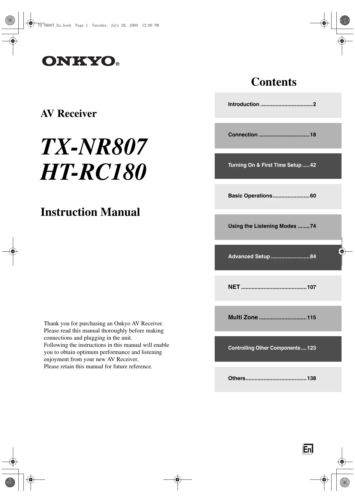
- € & TK-NRSOT_En. book Page 1 Tuesday, July 28, 2009 12:00 PM ONKYO. Contents AV Receiver mere Connection …. TX-NRS07 HT. R C1 S0 Turning On & First Time Setup Basic Operations. Instruction Manual Using the Listening Modes …….74 Advanced Setup NET
- Multi Zone … Thank you for purchasing an Onkyo AV Receiver. Please read this manual thoroughly before making connections and plugging in the unit. Following the instructions in this manual will enable you to obtain optimum performance and listening enjoyment from your new AV Receiver. Please retain this manual for future reference. Controlling Other Components : Others. p. 12
€ & TK-NRSOT_En. book Page 2 Tuesday, July 28, 2009 12:00 PM
The lighining flash with arrowhead symbol, within an equilateral triangle, is intended to alert the user to the À presence of uninsulated “dangerous voltage” within the products enclosure that may be of sufficient magnitude to constitute a risk of electric shock to persons. The exclamation point within an equilateral triangle is intended to alert the user to the presence of important operating and maintenance (servicing) instructions in the literature accompanying the appliance. Important Safety Instructions Read these instructions. Keep these instructions. Heed all warnings. Follow all instructions. Do not use this apparatus near water. Clean only with dry cloth. Do not block any ventilation openings. Install in accordance with the manufacturer’s instructions.
8. Do not install near any heat sources such as radia-
tors, heat registers, stoves, or other apparatus (including amplifiers) that produce heat.
9. Do not defeat the safety purpose of the polarized or
grounding-type plug. À polarized plug has two blades with one wider than the other. À grounding type plug has two blades and a third grounding prong. The wide blade or the third prong are pro- vided for your safety. If the provided plug does not fit into your outlet, consult an electrician for replacement of the obsolete outlet.
10. Protect the power cord from being walked on or
pinched particularly at plugs, convenience recepta- cles, and the point where they exit from the appara- tus.
11. Only use attachments/accessories specified by the
manufacturer. RH hESRE
12. Use only with the cart, PORTABLE CART WARNING
stand, tripod, bracket, or table specified by the manu- facturer, or sold with the apparatus. When a cart is used, use caution when À moving the cart/apparatus ss1z5 combination to avoid injury from tip-over.
13. Unplug this apparatus during lightning storms or
when unused for long periods of time.
14. Refer all servicing to qualified service personnel.
Servicing is required when the apparatus has been damaged in any way, such as power-supply cord or plug is damaged, liquid has been spilled or objects have fallen into the apparatus, the apparatus has been exposed to rain or moisture, does not operate normally, or has been dropped.
15. Damage Requiring Service
Unplug the apparatus from the wall outlet and refer servicing to qualified service personnel under the following conditions: A. When the power-supply cord or plug is dam- aged, B. If liquid has been spilled, or objects have fallen into the apparatus, C. If the apparatus has been exposed to rain or water, D. If the apparatus does not operate normally by following the operating instructions. Adjust only those controls that are covered by the oper- ating instructions as an improper adjustment of other controls may result in damage and will often require extensive work by a qualified tech- nician to restore the apparatus to its normal operation, E. Ifthe apparatus has been dropped or damaged in any way, and EF When the apparatus exhibits a distinct change in performance this indicates a need for service.
16. Object and Liquid Entry
Never push objects of any kind into the apparatus through openings as they may touch dangerous volt- age points or short-out parts that could result in a fire or electric shock. The apparatus shall not be exposed to dripping or splashing and no objects filled with liquids, such as vases shall be placed on the apparatus. Don't put candles or other burning objects on top of this unit.
Always consider the environmental issues and fol- low local regulations when disposing of batteries.
18. If you install the apparatus in a built-in installation,
such as a bookcase or rack, ensure that there is ade- quate ventilation. Leave 20 cm (8") of free space at the top and sides and 10 em (4") at the rear. The rear edge of the shelf or board above the apparatus shall be set 10 cm (4") away from the rear panel or wall, creating a flue- like gap for warm air to escape.
€ & TK-NRSOT_En. book Page 3 Tuesday, July 28, 2009 12:00 PM
1. Recording Copyright—Unless it's for personal use
only, recording copyrighted material is illegal with- out the permission of the copyright holder.
2. AC Fuse—The AC fuse inside the unit is not user-
serviceable. If you cannot turn on the unit, contact your Onkyo dealer.
3. Care—Occasionally you should dust the unit all
over with a soft cloth. For stubborn stains, use a soft cloth dampened with a weak solution of mild deter- gent and water. Dry the unit immediately afterwards with a clean cloth. Don't use abrasive cloths, thin- ners, alcohol, or other chemical solvents, because they may damage the finish or remove the panel let- tering.
TION CAREFULLY. AC outlet voltages vary from country to country. Make sure that the voltage in your area meets the voltage requirements printed on the unit's rear panel (e.g., AC 230 V, 50 Hz or AC 120 V, 60 Hz). The power cord plug is used to disconnect this unit from the AC power source. Make sure that the plug is readily operable (easily accessible) at all times. Pressing the [ON/STANDB Y] button to select Standby mode does not fully shutdown the unit. If you do not intend to use the unit for an extended period, remove the power cord from the AC outlet.
5. Preventing Hearing Loss
Caution Excessive sound pressure from earphones and head- phones can cause hearing loss.
6. Batteries and Heat Exposure
Warning Batteries (battery pack or batteries installed) shall not be exposed to excessive heat as sunshine, fire or the like.
7. Never Touch this Unit with Wet Hands—Never
handle this unit or its power cord while your hands are wet or damp. If water or any other liquid gets inside this unit, have it checked by your Onkyo dealer.
+_If you need to transport this unit, use the original packaging to pack it how it was when you origi- nally bought it. Do not leave rubber or plastic items on this unit for a long time, because they may leave marks on the case. This unit’s top and rear panels may get warm after prolonged use. This is normal. If you do not use this unit for a long time, it may not work properly the next time you turn it on, so be sure to use it occasionally. For U.S. models FCC Information for User CAUTION: The user changes or modifications not expressly approved by the party responsible for compliance could void the user’s authority to operate the equipment. NOTE: This equipment has been tested and found to comply with the limits for a Class B digital device, pursuant to
Part 15 of the FCC Rules. These limits are designed to
provide reasonable protection against harmful interfer- ence in a residential installation. This equipment generates, uses and can radiate radio fre- quency energy and, if not installed and used in accor- dance with the instructions, may cause harmful interference to radio communications. However, there is no guarantee that interference will not occur in a partic- ular installation. If this equipment does cause harmful interference to radio or television reception, which can be determined by turning the equipment off and on, the user is encouraged to try to correct the interference by one or more of the following measures: Reorient or relocate the receiving antenna. Increase the separation between the equipment and receiver. Connect the equipment into an outlet on a circuit dif- ferent from that to which the receiver is connected. Consult the dealer or an experienced radio/TV techni- cian for help. For Canadian Models
NOTE: THIS CLASS B DIGITAL APPARATUS
7 TICNRSOT_En. book Page 4 Tuesday, July 28, 2009 12:00 PU 7 ds n
Precautions—Continued Supplied Accessories For British models Make sure you have the following accessorik Replacement and mounting of an AC plug on the power supply cord of this unit should be performed only by qualified service personnel. IMPORTANT The wires in the mains lead are coloured in accordance with the following code: Remote controller & two batteries (AA/R6) (Note for China: The battery for the remote controller is not supplied for this unit.) Blue: Neutral Brown: Live As the colours of the wires in the mains lead of this appa- ratus may not correspond with the coloured markings identifying the terminals in your plug, proceed as fol- lows: The wire which is coloured blue must be connected to the terminal which is marked with the letter N or coloured black. The wire which is coloured brown must be connected to Indoor FM antenna the terminal which is marked with the letter L or coloured red. IMPORTANT The plug is fitted with an appropriate fuse. If the fuse needs to be replaced, the replacement fuse must AM loop antenna approved by ASTA or BSI to BS1362 and have the same ampere rating as that indicated on the plug. Check for the ASTA mark or the BSI mark on the body of the fuse. À If the power cord’s plug is not suitable for your socket | 4 outlets, cut it off and fit a suitable plug. Fit a suitable fuse 4 in the plug. Power cord (Plug type varies from country to country.) For European Models Declaration of Conformity We, ONKYO EUROPE À à ELECTRONICS GmbH ER LIEGNITZERSTRASSE 6, RE 82194 GROEBENZELL, Speaker cable labels GERMANY declare in own responsibility, that the ONKYO product described in this instruction manual is in compliance with the corresponding technical standards such as EN60065, EN55013, ENS5020 and EN61000- GROEBENZELL, GERMANY Power-plug adapter Only supplied in certain countries. Use this adapter if K. MIYAGI your AC outlet does not match with the plug on the AV ONKYO EUROPE ELECTRONICS GmbH receivers power cord (adapter varies from country to country). “How to mount the AC plug: In catalogs and on packaging, the letter at the end of the product name indicate the color. Specifications and operations are the same regardless of color.
€ & TK-NRSOT_En. book Page 5 Tuesday, July 28, 2009 12:00 PM
Contents Introduction Important Safety Instruction: Précautions … Supplied Accessories Features Front & À Front Panel Display. 10 Rear Panel 11 Remote Controller Installing the Batteries . Aiming the Remote Controller Controlling the AV Receive: About Home Theater . Enjoying Home The: Connection Connecting the AV receiver. 18 Connecting Your Speakers. 18 Bi-amping the Front Speakers 21 Connecting Antenna . 22 About AV Connections 24 Connecting Components with HDMI 25 Connecting Both Audio & Video … 27 Which Connections Should | Use Connecting a TV or Projector Connecting a DVD Player... Connecting a VCR or DVD Recorder for Playbac Connecting a VCR or DVD Recorder for Recording . Gonnecting a Satellite, Cable, Terrestrial Set-top box, or Other Video Source. Connecting a Game Console … Connecting a Camcorder or Other Device Connecting a CD Player or Tumtable. GConnecting a Cassette, CDR, MiniDi Recorder … Connecting a Power Amplifiet Connecting an RI Dock. Connecting a Dock with the Universal Port Connector. Connecting Onkyo RI Components Connecting the Power Cord Turning On & First Time Setup Turning On the AV receiver Tuning On and Standby First Time Setup. Monitor Setup (TX-NR807). Selectng the Language used for the onscreen setup menu Using the Onscreen Setup Menus: Using the Display to change the settings . Monitor Out Setup . Video Input Setu Digital Audio Input Setup Speaker Settings … TV Format Setup (European, Australian and Asian models) FM/AM Frequency Step Setup . Changing the Input Display Audyssey MultEQ® Room Correction and Speaker Setup Basic Operations Basic Operations … Selecting the Input Source . Adjusting the Bass & Treble Displaying Source Informatior Setting the Display Brightnes: Muting the AV Receive Using the Sleep Timer.. Selecting Speaker Layou Using Headphones Using Easy Macros Listening to the Radio Using the Tuner. Presetting AM/FM Stations. Using RDS (European models) UP-A1 series Dock for iPod. About the UP-A1 series Dock Compatible iPod models . Function Overview Controlling iPod . Recording . Using the Listening Modes Using the Listening Modes . Selecting Listening Modes. Listening Modes Available for Each Source Format About the Listening Modes Advanced Setup Advanced Setup . Onscreen Setup Menu: Speaker Setup Audio Adjust Source Setu Assigning Listening Modes to Input Sources Miscellaneous (Volume/OSD) Setup . Hardware Setup. Lock Setup... Digital Input Signal Format Using the Audio Settings NET NET Connecting the AV Receiver. Listening to Internet Radio. Playing Music Files on a Serve Network Settings. Multi Zone Multi Zone. Multiroom Capability Connecting Zone 2 Connecting Zone 3 Setting the Powere. Setting the Multi Zone. Using Zone 2/3 .. Using the Remote Controller in Zone 2/3 and Multiroom Control Kits (TX-NR807) Controlling Other Components Controlling Other Components. Preprogrammed Remote Control Code: Looking up for Remote Control Code Entering Remote Control Codes... Remote Control Codes for Onkyo Components Connected via R1. Resetting REMOTE MODE Buttons Resetting the Remote Controller . Controlling a TV. Controling a DVD Player, or DVD Recorder Controllng a VCR or PVR … Controlling a Satellite Receiver or Cable Receiver Controling a CD Player, CD Recorder, or MD Recorder . Controlling an RI Dock Controling a Cassette Recorde: Activities Setup … Learning Commands Using Normal Macros . Others Troubleshooting.. Specifications (TX-NR807). Specifications (HT-RC180) . Video Resolution Chart To reset the AV receiver to its factory defaults, turn it on and, while holding down the [VCR/DVR] button, press the [ON/STANDBY] button (see page 138).
€ & TK-NRSOT_En. book Page 6 Tuesday, July 28, 2009 12:00 PM
Features Amplifier (TX-NR807) + 135 Watts/Channel @ 8 ohms (FTC) + 180 Watts/Channel @ 6 ohms (IEC) + 230 Watts/Channel @ 6 ohms (JEITA) (HT-RC180) + 110 Watts/Channel @ 8 ohms (FTC) WRAT-Wide Range Amplifier Technology (5 Hz-100 KHz bandwidth) Linear Optimum Gain Volume Cireuitry Push-Pull Amplifier Design with 3-Step Inverted Dar- lington Circuitry H.C.PS. (High Current Power Supply) Massive High Power Transformer Processing THX Select2 Plus ! Certified HDMI Video Upscaling (to 1080p Compatible) with Faroudja DCDi Cinema Enhancement HDMI ver.1-3a with (Deep Color x.x.Colgr Lip Syne, DTS"?-HD Master Audio, Dolby TrueHD'Ÿ, DSD and Multi-CH PCM) Dolby Pro Logic 1123 high) Audyssey Dynamic Surround ExpansionM" for New Surround Channels (front-wide/front-high) DTS Surround Sensation Speaker/Headphone Tech- nology'? 4 DSP Modes for Gaming; Rock/Sports/Action/RPG Non-Scaling Configuration Direct Mode and Pure Audio Mode Music Optimizer * for Digital Music Files A-Form Listening Mode Memory Latest Burr-Brown 192 KHz/24-Bit DAC Improves Jiter Performance for Cleaner Sound Two TI (Aureus) 32-bit Processing DSP — New Surround Format (front- Connections + 6 HDMI Inputs and 1 Output (TX-NR807) 5 HDMI Inputs and 1 Output (HT-RC180) Onkyo RIHD for System Control 6 Digital Inputs (3 Optical/3 Coaxial) Universal Port for UP-A1 (Dock for the iPod) HD Radio!" tuner module (North American models)/ DAB+ tuner module (European and Australian mod- els) Dual Subwoofer Pre Out SIRIUS"# Satellite Radio Connectivity (TX-NR807: North American models) Banana Plug-Compatible Speaker Posts 7 Powered Zone 2/3 Internet Radio* Connectivity (SIRIUS Internet Radio ?/vTuner/Last.fm/Pandora/Rhapsody)
- Services available may vary depending on the region. + Network Capability for Streaming Audio Files + Bi-Amping Capability for FL/FR with SBL/SBR Miscellaneous + 40 SIRIUS Ÿ/AM/FM Presets (TX-NR807: North American models) + 40 AM/FM Presets (TX-NR807: Taiwan, European, Australian and Asian models and HT-RC180) + Audyssey MultEQ®"® to Correct Room Acoustic Problems + Audyssey Dynamic EQTM" for Loudness Correction + Audyssey Dynamic VolumerM"® + Crossover Adjustment (40/50/60/70/80/90/100/120/150/200 Hz) + AV Sync Control Function (up to 250 ms) + Bi-Directional Preprogrammed (with onscreen dis- play setup) RI-Compatible Learning Remote with 4 Activities and Mode-Key LEDs THX nd the THX logo are trademarks of THX Ltd. which may be registered in son dictions. AI rights reserved. ‘2 Se dtsu5 Master Audio Surround Sensation Manufactured under license under U.S. Patent #'s: 5,451,942; 5956674; 5,974,380; 5,978,762; 6.226.616: 6.487.535;
7.212.872: 7,333,929; 7.302.195; 7.272.567 & other ULS. and
worldwide patents issued & pending. DTS is a registered trade- mark & the DTS logos, Symbol, DTS-HD Master Audio and DTS Surround Sensation are trademarks of DTS, Inc. ©1996-2008 DTS, Inc. AI Rights Reserved. ‘8. MIDOLBY TRUEIE | “PRO LOGIC Iz | Manufactured under license from Dolby Laboratories. “Dolby”, “Pro Logic”, “Surround EX” and the double-D symbol are trademarks of Dolby Laboratories. *4. Music Optimizer! is a trademark of Onkyo Corporation. s HDMI HDMI, the HDMI logo and High Definition Multimedia Inter- face are trademarks or registered trademarks of HDMI Licens- ing, LLC. $-H) Radio HD Radio’ and the HD Radio Ready logo are proprietary trademarks of iBiquity Digital Corporation To receive HD Radio broadcasts, you must install an Onkyo UP-HT1 HD Radio tuner module (sold separately). *7. In Europe, using banana plugs to connect speakers 10 an audio amplifier is prohibited.
V7 TI-NRSO7_En. book Page T Tuesday, July 28, 2009 12:00 PA Features —Continued # sIRIUS# SIRIUS© SIRIUSN SIRIUS SIRIUS, XM and all related marks and logos are trademarks of Sirius XM Radio Inc. and its subsidiaries. All other marks and logos are the property of their respective owners. AI rights reserved. SIRIUS and XM subscriptions sold separately. Taxes and a one-time activation fee may apply. XM tuners and home docks or SIRIUS tuners (each sold separately) are required to receive the SIRIUS or XM satellite radio service. All program- ming and fees subject to change. It is prohibited to copy, decom- pile, disassemble, reverse engineer, hack, manipulate or otherwise make available any technology or software inc rated in receivers compatible with the SIRIUS or XM Radio Systems. Service not available in Alaska and Hawaii. È AUDYSSEY DIX
Manufactured under license from Audyssey Laboratories. U.S and foreign patents pending. Audyssey MultEQ®, Audyssey Dynamic Surround Expansion TM Audyssey Dynamic Volume?" and Audys: are trademarks of Audyssey Laboratories y Dynamic EQTN THX Select2 Plus Before any home theater component can be THX Select2 Plus certified, it must pass a rigorous series of quality and performance tests. Only then can a product feature the THX Select? Plus logo, which is your guar- antee that the Home Theater products you purchase will give you superb performance for many years to come. THX Select? Plus requirements define hundreds of À parameters, including power amplifier performance, S 4 and pre-amplifier performance and operation for both digital and analog domains. THX Select? Plus receivers also feature proprietary THX technologies (e.g., THX Mode) which accurately translate movie soundtracks for home theater playback. registered trademark of Xantech Corporation. a registered trademark of Niles Audio Corporation Apple and iPod are trademarks of Apple Inc. registered in the U.S. and other countries. © “xv.Color” is a trademark of Sony Corporation. Rhapsody and the Rhapsody logo are registered trademarks of RealNetworks, Inc. + “DLNAŸ, the DLNA Logo and DLNA CERTIFIED are trademarks, service marks, or certification marks of the Digital Living Network Alliance.” CTX-NR807) This product incorporates copyright protection technology that is protected by U.S. patents and other intellec- tual property rights. Use of this copyright protection technol- ogy must be authorized by Macrovision Corporation, and is intended for home and other limited consumer uses only unless otherwise authorized by Macrovision. Reverse engineering or disassembly is prohibited.
ë & TK-NRSOT_En. book Page 8 Tuesday, July 28, 2009 12:00 PM
Front & Rear Panels Front Panel DO ©8006 © oN«Yo
© Front flap Pull here to open the flap The actual front panel has various logos printed on it. They are not shown here for clarity. The page numbers in parentheses show where you can find the main explanation for each item. @ ON/STANDBY button (42) This button is used to set the AV receiver to On or Standby. © STANDBY indicator (42) This indicator lights up when the AV receiver is in Standby mode, and it flashes while a signal is being received from the remote controller. @ ZONE 2 indicator (120) This indicator lights up when Zone 2 is selected. @ ZONE 3 indicator (120) This indicator lights up when Zone 3 is selected. ® Input selector buttons (60) These buttons are used to select from the following input sources: DVD/BD, VCR/DVR, CBL/SAT, GAME, AUX, TV/TAPE, TUNER, CD, PHONO, PORT, NET. © Remote control sensor/transmitter (14) The sensor receives control signals from the remote controller. The transmitter transmits setting data to the remote controller. © Display See “Display” on page 10. DISPLAY button (61) This button is used to display various information about the currently selected input source. MASTER VOLUME control (60) and indicator This control is used to adjust the volume of the AV receiver to co dB, -81.5 dB through +18.0 dB (rel- ative display). The volume level can also be displayed as an abso- lute value. See “Volume Setup” on page 98. PURE AUDIO button and indicator (74) Selects the Pure Audio listening mode. The indica- tor lights up when this mode is selected. Pressing this button again selects the previous listening mode.
€ & TK-XRSO7_En. book Page 9 Tuesday, July 28, 2009 12:00 PM ds N Front & Rear Panels—Continued (North American and Taïwan models) (European, Australian and Asian models)
The page numbers in parentheses show where you can find the main explanation for each item. © PHONES jack (63) @ DIMMER button (62) This 1/4-inch phone jack is for connecting a stan- (North American and Taïwan models) ds dard pair of stereo headphones for private listening. This button is used 10 adjust the display brightness. à d @ ZONE 2, ZONE 3, and OFF buttons (120) RT/PTY/TP button (68) 7 The [ZONE 2] button is used when turn on Zone 2. (European, Australian and Asian models) The [ZONE 3] button is used when turn on Zone 3. This button is used for RDS (Radio Data System). The [OFF] button is used to turn off Zone 2 or The [RT/PTY/TP] button does not work in areas Zone 3. where RDS broadcasts are not available. See “Using @ TONE button (61, 121) RDS (European models)” on page 68. Used to adjust the tone (bass and treble) for the @ MEMORY button (67) main room, the tone and balance for Zone 2 or This button is used when storing or deleting radio Zone 3. presets. @ LEVEL button (121) @ TUNING MODE button (66) Used when adjusting the volume level of Zone 2 or This button is used to select the Auto or Manual Zone 3. tuning mode. @ MONITOR OUT button (TX-NR807) (43) @ Arrow, TUNING, PRESET and ENTER Used to set the “Monitor Out” setting. buttons Re-EQ button (HT-RC180) (105) When the AM or FM input source is selected, the Used to turn the Re-EQ function on or off. TUNING [AJ/LY] buttons are used to tune the tuner, @ LISTENING MODE buttons (74) and the PRESET [<J/(> ] buttons are used to select MOVIENTV button radio presets (see pages 67, 69). Selects the listening modes intended for use with When the onsereen setup menus are used they Work movies and TV. as Re = qe used net ae ". MUSIC button is “a mel utton is also used with the Selects the listening modes intended for use with SOTEEN SEP Menus. music. @ SETUP button GAME button This pion is used to js the een setup Selects the listening modes intended for use with MENUS Mat appear on Le connectec TN. video games. @ RETURN button THX button This button is used to return to the previously dis- Selects the THX listening modes. played onsereen setup menu.
€ & TK-NRSOT_En. book Page 10 Tuesday, July
2009 12:00 PM Front & Rear Panels—Continued @ SETUP MIC jack (55) Audyssey MultEQ® Room Correction and Speaker Setup microphone connects here. @ AUX INPUT (36) This input can be used to connect a camcorder, game console, and so on. There are jacks for com- posite video, analog audio, and optical digital audio. Display & Up [>] and Down [<] buttons (61, 104, 121) Used to adjust the tone (bass and treble) for the main room and the volume, tone and balance for Zone 2 or Zone 3. & MUSIC OPTIMIZER button (105) Turns the Music Optimizer on or off. @ POWER switch (42) (European, Australian and Asian models) This is the main power switch. When set to OFF, the AV receiver is completely shutdown. It must be set to ON to set the AV receiver to On or Standby. For detailed information, see the pages in parentheses. @ Speaker/channel indicators Indicate the speaker channels used by the current listening mode. The following abbreviations indicate which audio channels are outputted for the current listening mode. LW: Front wide left LH: Front high left RH: Front high right RW: _ Front wide right FL: Frontleft C: Center FR: Front right SL: Surround left SW: Subwoofer (Low Frequency Effects) SR: Surround right SBL: Surround back left SB: Surround back SBR: Surround back right @ ZONE 2 indicator (120) Lights up when Powered Zone 2 is being used. @ ZONE 3 indicator (120) Lights up when Powered Zone 3 is being used. @ Listening mode and format indicators (74) Show the selected listening mode and audio input signal format.
® NETWORK indicator (108) Lights up when the AV receiver can establish a con- nection to the media server or internet radio sta- tions. @ Tuning indicators RDS (European models) (68): Lights up when tuned to a radio station that supports RDS (Radio Data System). AUTO (66): Lights up when Auto Tuning mode is selected for AM or FM radio. Goes off when Manual Tuning mode is selected. TUNED (66): Lights up when tuned to a radio station. FM STEREO (66): Lights up when tuned to a stereo FM station. @ SLEEP indicator (62) Lights up when the Sleep function has been set. Bi AMP indicator (21) Lights up when the “Speakers Type(Front)” setting is set to “Bi-Amp”. © Headphone indicator (63) Lights up when a pair of headphones are plugged into the PHONES jack.
€ & TK-XRSO7_En. book Page 11 Tuesday, July 28, 2009 12:00 PM
Front & Rear Panels—Continued @ Audyssey indicator (54, 87) © Message area Flashes during Audyssey MultEQ® Room Correc- Displays various information. tion and Speaker Setup. Lights up when the “Equal- @ Audio input indicators izer Settings” is set to “Audyssey” or Indicate the type of audio input that's selected as the Audyssey Dynamic Surround Expansion’ listen- audio source: HDMI, ANALOG, or DIGITAL. ing mode is selected. @ Volume level (60) Dynamic EQ indicator (91): à ONE cos Displays the volume level. “Dynamic EQ" lights when “Dynamic EQ° is . enable. @ MUTING indicator (62) Dynamic Volume indicator (91): Flashes while the AV receiver is muted. “Vol” lights when “Dynamic Volume” is enable. Rear Panel (TX-NR807) * North American models DOGPEE D* ® © VO e60 ff s| | Se GoC L 66606 4 i ] È [opolfel ( [oKolo)
oddddds @ DIGITAL OPTICAL IN 1 and 2 These optical digital audio inputs are for connecting components with optical digital audio outputs, such as CD and DVD/BD players. They”re assignable, which means you can assign each one to an input selector to suit your setup. See “Digital Audio Input Setup” on page 50. DIGITAL COAXIAL IN 1, 2, and 3 These coaxial digital audio inputs are for connect- ing components with coaxial digital audio outputs, such as CD and DVD/BD players. They’re assign- able, which means you can assign each one to an input selector to suit your setup. See “Digital Audio Input Setup” on page 50.
This RI (Remote Interactive) jack can be con- nected to an fRI jack on another Onkyo AV compo- nent. The AV receiver’s remote controller can then be used to control that component. To use RI, you must make an analog audio connection (RCA) between the AV receiver and the other AV compo- nent, even if they are connected digitally. @ RS232 (TX-NR807) Terminal for control. ® UNIVERSAL PORT This port is for connecting the component with the Universal Port connector such as UP-AI series Dock. ETHERNET This port is for connecting the AV receiver to your Ethernet network (e.g., router or switch) for playing music files on a networked computer or media server, or for listening to Internet radio.
ë & TK-NRSOT_En. book Page 12 Tuesday, July
2009 12:00 PM Front & Rear Panels—Continued @ SIRIUS antenna (TX-NR807: North American models) This jack is for connecting a SIRIUS Satellite Radio antenna, sold separately (see the separate SIRIUS instructions). MONITOR OUT These S-Video and composite video jacks should be connected to a video input on your TV or projector. © HDMIIN 1-6 and OUT (TX-NR807) HDMI IN 1-5 and OUT (HT-RC180) HDMI (High Definition Multimedia Interface) con- nections carry digital audio and digital video. The HDMI inputs are for connecting components with an HDMI output, such as a DVD player, Blu- ray Disc Player, DVD recorder, or DVR (digital video recorder). They’re assignable, which means you can assign each one to an input selector to suit your setup. See “HDMI Input Setup” on page 48. The HDMI output is for connecting a TV or projec- tor with an HDMI input. COMPONENT VIDEO IN 1 and 2 These RCA component video inputs are for con- necting components with a component video out- put, such as a DVD player, DVD recorder, or DVR (digital video recorder). They’re assignable, which means you can assign each one to an input selector 1o suit your setup. See “Component Video Setup” on page 49.
€ COMPONENT VIDEO MONITOR OUT
These RCA component video outputs are for con- necting a TV or projector with a component video input. @ FM ANTENNA This jack is for connecting an FM antenna. AM ANTENNA These push terminals are for connecting an AM antenna. @ IR IN/OUT (TX-NR807) A commercially available IR receiver can be con- nected to the IR IN jack, allowing you to control the AV receiver while you're in Zone 2/3, or control it when it's out of sight, for example, installed in a cabinet. A commercially available IR emitter can be con- nected to the IR OUT jack to pass IR (infrared) remote control signals through to other components. 12V TRIGGER OUT ZONE 2 (TX-NR807) This output can be connected to the 12-volt trigger input on a component in Zone 2. When Zone 2 is turned on, a 12-volt trigger signal is output. 12V TRIGGER OUT ZONE 3 (TX-NR807) This output can be connected to the 12-volt trigger input on a component in Zone 3. When Zone 3 is turned on, a 12-volt trigger signal is output. @ AC INLET The supplied power cord is connected here. The other end of the power cord should be connected to a suitable wall outlet. @& GND screw This screw is for connecting a turntable’s ground wire. @ PHONO IN These analog audio inputs are for connecting a turn- table. @ CDIN These analog audio inputs are for connecting a CD player’s analog audio output.
These analog audio inputs and outputs are for con- necting a TV or recorder with an analog audio input and output (cassette, Mini Disc, etc.). @ GAMEIN Here you can connect a game console, etc. Input jacks include S-Video, composite video, and analog audio.
Here you can connect a cable/satellite receiver, set- top box, etc. Input jacks include S-Video, composite video, and analog audio.
Here you can connect a VCR or DVR (digital video recorder). Input and output jacks include S-Video, composite video, and analog audio.
Here you can connect a DVD/BD player. Input jacks include S-Video, composite video, and analog audio. You can connect a DVD/BD players 2-chan- nel analog audio output. @ PRE OUT: FRONT L/R, CENTER, SURR L/R, and SURR BACK L/R These multichannel analog audio outputs can be connected to the analog audio input on a multichan- nel power amplifier for when you want to use the AV receiver solely as a preamplifier.
@ PRE OUT: SUBWOOFER
These analog audio outputs can be connected to a powered subwoofer. You can connect the powered subwoofer with two PREOUT: SUBWOOFER jacks respectively. The same signal is output from each jack.
@ PRE OUT: ZONE 2, ZONE 3 L/R
These analog audio outputs can be connected to the line inputs on amplifiers in Zone 2 and Zone 3.
XP TE NRSOZ_En. book Page 13 Tuesday, July 28, 2009 12:00 PM 7 ds n Front & Rear Panels—Continued @ FRONT L/R, CENTER, SURR/ZONE 3 L/R, SURR BACK/ZONE 2 L/R, FRONT HIGH L/R, and FRONT WIDE L/R These terminal posts are for connecting the front L/R, center, surround/zone 3 L/R, surround back/ zone 2 L/R, front high L/R, and front wide L/R speakers. The FRONT L/R and SURR BACK/ZONE 2 L/R terminal posts can be used with front speakers and surround back speakers respectively, or used to bi- amp the front speakers. See “Bi-amping the Front Speakers” on page 21”. The SURR BACK/ZONE 2 L/R terminals can be used with surround back speakers respectively, or used to connect the speakers in Zone 2. See “Connecting Zone 2” on page 116. The SURR/ZONE 3 L/R terminals can be used with surround speakers respectively, or used to connect the speakers in Zone 3. See “Connecting Zone 3” on page 117. (See pages 18-41 for connection information. ) 4 a À
€ & TI-NRSOT_En. book Page 14 Tuesday, July
2009 12:00 PM Remote Controller Installing the Batteries To open the battery compartment, press the small lever and remove the cover.
2 Insertthe two supplied batteries (AA/R6) in accordance with the polarity diagram inside the battery compartment. K] Replace the cover and push it shut. Notes: +_Ifthe remote controller doesn't work reliably, try replacing the batteries. + Don't mix new and old batteries or different types of batteries. +_If you intend not to use the remote controller for a long time, remove the batteries to prevent damage from leakage or corrosion. + Expired batteries should be removed as soon as possi- ble to prevent damage from leakage or corrosion. Aiming the Remote Controller To use the remote controller, point it at the AV receiver’s remote control sensor, as shown below. Transmission Remote control sensor AV receiver 80° off center Approx. 16 ft. (5 m) (Lef/Right/Up/Down) Received Transmitter AV receiver Incoming sensor 15° off center Approx. 16 ft. (5 m) (Lef/Right/Up/Down) Notes: The remote controller may not work reliably if the AV receiver is subjected to bright light, such as direct sun- light or inverter-type fluorescent lights. Keep this in mind when installing. If another remote controller of the same type is used in the same room, or the AV receiver is installed close to equipment that uses infrared rays, the remote control- ler may not work reliably. Don't put anything, such as a book, on the remote con- troller, because the buttons may be pressed inadvert- ently, thereby draining the batteries. The remote controller may not work reliably if the AV receiver is installed in a rack behind colored glass doors. Keep this in mind when installing. The remote controller will not work if there's an obstacle between it and the AV receiver’s remote con- trol sensor. ‘When the remote control codes have been registered and you want to operate another component (page 125), or when you want to operate an Onkyo component without fRI connection, point the remote controller at the other component to use it. ‘When you want to operate an Onkyo component with RI connection or an FRIHID -compatible compo- nent connected via HDMI (pages 127, 128), point the remote controller at the AV receiver’s remote control sensor.
7 TIC NRSOT_En. book Page 15 Tuesday, July 28, 2009 12:00 PW 7 ds n
Remote Controller —Continued Controlling the AV Receiver For detailed information, see the pages in parentheses. @ STANDBY button (42) Sets the AV receiver to Standby. @ ON button (42) Turns on the AV receiver. @ ACTIVITIES buttons (64, 137) Used with the MACRO function. @ REMOTE MODE/INPUT SELECTOR buttons (60, 127 to 133) Selects the remote controller modes and the input sources. @ SP LAYOUT button (63) This button is used to change Front High speakers and Front Wide speakers and Surround Back speak- ers. © Arrow [AJ{YJ{<J/[>] and ENTER buttons Used to select and adjust settings. @ SETUP button Used to change settings. LISTENING MODE buttons (74) Used to select the listening modes. © DIMMER button (62) Adjusts the display brightness. \ d ] @ DISPLAY button (61) / Displays information about the current input source. @ MUTING button (62) Mutes or unmutes the AV receiver. @ VOL [AJ[Y] button (60) Adjusts the volume of the AV receiver regardless of the currently selected remote controller mode. @ VIDEO button (43, 47, 95) Used to change video settings. RETURN button Returns to the previous display when changing set- tings. @ AUDIO button (104) Used to change audio settings. ‘When the “Audio TV Out” setting is set to “On” (page 100), this button is disabled. @ SLEEP button (62) Used with the Sleep function. To control the AV receiver, press the [RECEIVER] button to select Receiver mode. You can also use the remote controller to control your DVD/BD player, CD player, and other components. See page 125 for more details. “1. When you want to change the remote controller mode without changing the current input source, press the [MODE] button and within about eight seconds, press the REMOTE MODE button. Then, with the AV receiver's remote controller, you can control the component corresponding to the button you pressed. es 15 s sit
XP TE NRSOZ_En. book Page 16 Tuesday, July 28, 2009 12:00 PM 7 ds n
Remote Controller —Continued Æ Controlling the tuner To control the AV receiver’s tuner, press the [TUNER] (or [RECEIVER]) button. You can select AM or FM by pressing the [TUNER] but- ton repeatedly. © Arrow [AJ[Y] buttons Used to tune into radio stations. © D.TUN button (66) (TUNER remote mode only) Selects the Direct tuning mode. © DISPLAY button Displays information about the band, frequency, preset number, and so on. © CH +/- button (67) Used to select radio presets. © Number buttons (66, 67) Used to select radio stations directly in the Direct tuning mode. Also you can select a preset directly. Note: An Onkyo cassette recorder connected via FRI can also be controlled in Receiver mode (see page 133).
€ & TK-XRSO7_En. book Page 17 Tuesday, July 28, 2009 12:00 PM
About Home Theater Enjoying Home Theater Thanks to the AV receiver”’s superb capabilities, you can enjoy surround sound with a real sense of movement in your own home—just like being in a movie theater or concert hall. With DVDs you can enjoy DTS and Dolby Digital. With analog or digital TV, you can enjoy Dolby Pro Logic IIx, DTS Neo:6, or Onkyo’s original DSP listening modes. You can also enjoy THX Surround EX (THX-certified THX speaker system recommended). Front left and right speakers These output the overall sound. Their role in a home theater is to provide a solid anchor for the sound image. They should be positioned facing the listener at about ear level, and equidistant from the TV. Angle them inward so as to create a triangle, with the listener at the apex. Front high left and right speakers These speakers are necessary to enjoy Dolby Pro Logic Ilz eight, Audyssey Dynamic Surround Expansion"", etc. They enhance significantly the spatial experience. Position them at least 3.3 feet (100 cm) above the front left and right speakers (and as high as possible). Although it is acceptable to place left and right at an angle slightiy wider than the front left and right speakers. Front wide left and right speakers These speakers are necessary to enjoy etc. They enhance significantly the spatial experience. Position them at the outside of the front left and right speakers. Although it is acceptable to place left and right at an angle slightiy wider than the front left and right speakers. Center speaker —— This speaker enhances the front left and right speakers, making sound movements dis- tinct and providing a full sound image. In movies it's used mainly for dialog. Position it close to your TV fac- ing forward at about ear level, or at the same height as the front left and right speakers. Surround back left and right speakers These speakers are necessary to enjoy Dolby Digital EX, DTS-ES Matrix, DTS-ES Discrete, THX Surround EX, etc. They enhance the realism of surround sound and improve sound localization behind the listener. Position them behind the listener about 2 to 3 feet (60 to 100 cm) above ear level. Subwoofer The subwoofer handies the bass sounds of the LFE (Low-Frequency Effects) channel. The volume and quality of the bass output from your subwoofer will depend on its position, the shape of your Surround left and right speakers listening room, and your listening posi- These speakers are used for precise sound positioning and to add tion. In general, a good bass sound can realistic ambience. be obtained by installing the subwoofer Position them at the sides of the listener, or slightly behind, about 2 to in a front corner, or at one-third the width 3 feet (60 to 100 cm) above ear level. Ideally they should be equidis- of the wall, as shown. tant from the listener. Tip: To find the best position for your subwoofer, while playing a movie or some music with good bass, experiment by placing your subwoofer at various positions within the room, and choose the one that provides the most satisfying results. 1/3 of wall position Audyssey Dynamic Surround Expansion’",
NP7 TI-NR8O7_En. book Page 18 Tuesday, July 28, 2009 12:00 PH Connecting the AV receiver Connecting Your Speakers Speaker Configuration For 7.1-channel surround-sound playback, you need seven speakers and a powered subwoofer. The following table indicates the channels you should use depending on the number of speakers that you have. Number of speakers: 2134/5167 7|7|8|8|9]|9]9|tw0ln Front left PAFATATATATATATFATA TA FAT ATATFAE Front right 'AFATArARATATATATArARArATAEAE Center 7 "AFARARARATATATArAEAEAEZ Surround left AFATARARATATArATARAEAEAEZ Surround right PAFArFATATATATATFATFATFATATFAEZ Surround back® 7 PAR 7 Surround back left 7 PA 7 Surround back right 7 PA 7 Front high left 7 7 7 "AFAE Front high right 7 7 7 "AFAE Front wide left 7 7 PAFANAEZ Front wide right 7 7 PAFANAEZ If you're using only one surround back speaker, connect it to the SURR BACK/ZONE 2 L terminals No matter how many speakers you use, a powered subwoofer is recommended for a really powerful and solid bass. To get the best from your surround sound system, you need to set the speaker settings. You can do this automatically (see page 54) or manually (see page 85). Note: 4 Front high, surround back and front wide speakers produce no sound at the same time. Attaching the Speaker Labels {North American, Taiwan, Australian and Asian mod- : x els) The AV receiver’s positive (+) speaker terminals are all «If you are using banana plugs, tighten the speaker ter- red (the negative (-) speaker terminals are all black). minal before inserting the banana plug. Speaker Color + Do not insert the speaker code directly into the center Frontiei Zone 210 WT hole of the speaker terminal. Front right, Zone 2 right Red Connecting a Powered Subwoofer Center Green Surround left, Zone 31e Blue Using a suitable cable, connect the AV receivers PRE Surround right, Zone 8 right Gray OUT: SUBWOOFER to an input on your powered sub- Sunound back et Zone 210 Bron woofer, as shown. If your subwoofer is unpowered and . you're using an external amplifier, connect the PRE Surround back right, Zone 2 right_| Tan OUT: SUBWOOFER (0 an input on the amp. Front high left White You can connect the powered subwoofer with two PRE- Front high right Red OUT: SUBWOOFER jacks respectively. Front wide left White The same signal is output from each jack. Front wide right Red The supplied speaker cable labels are also color-coded Powered subwoof and you should attach them to the positive (+) side of owered subwoofer each speaker cable in accordance with the above table. Then all you need to do is to match the color of each nC) 0 label to the corresponding speaker terminal. e LE D _ =. L 18 L @ LA
€ & TK-XRSO7_En. book Page 19 Tuesday, July 28, 2009 12:00 PM
Connecting the AV receiver—Continued Using Dipole Speakers Speaker Connection Precautions You can use dipole speakers for the surround left and Read the following before connecting your speakers: right, surround back left and right speakers. Dipole +_ You can connect speakers with an impedance of speakers output the same sound in two directions. between 4 and 16 ohms. If the impedance of any of the Dipole speakers typically have an arrow printed on them connected speakers is 4 ohms or more, but less than 6 to indicate how they should be positioned. The surround ohms, be sure to set the minimum speaker impedance left and right dipole speakers should be positioned so to “ohms” (see page 51). If you use speakers with a that their arrows point toward the TV/screen, while the lower impedance, and use the amplifier at high vol- surround back left and right and front high left and right ume levels for a long period of time, the built-in pro- and front wide left and right dipole speakers should be tection circuit may be activated. positioned so that their arrows point toward each other, +_ Disconnect the power cord from the wall outlet before as shown. making any connections. Dipole speakers Normal speakers + Read the instructions supplied with your speakers. + Pay close attention to speaker wiring polarity. In other IST To Eu words, connect positive (+) terminals only to positive mm à. 41 dr (+) terminals, and negative o rerminals only to nega- tive (—) terminals. If you get them the wrong way 2] el C2) around, the sound will be out of phase and will sound + Unnecessarily long, or very thin speaker cables may affect the sound quality and should be avoided. L ) ä De] + 1f you use 4 or 5 speakers, connect each of the two surround speakers to the SURR/ZONE 3 L/R termi- nals. Do not connect them to the SURR > > BACK/ZONE 2 L/R, FRONT WIDE L/R, or FRONT À HIGH L/R terminals. - Subwoofer … Front left speaker . Center speaker Front right speaker … Surround left speaker Surround right speaker Surround back left speaker
9. Front high left speaker
10.Front high right speaker 11.Front wide left speaker 12.Front wide right speaker NOnBEN = Be careful not to short the positive and negative wires. Doing so may damage the AV À receiver. & Make sure the metal core of the wire does not have contact with the AV receiver’s rear panel. Doing so may damage the AV receiver. Don't connect more than one cable to each speaker terminal. Doing so may damage the AV receiver. Don't connect one speaker to several terminals.
€ & TK-XRSO7_En. book Page 20 Tuesday, July 28, 2009 12:00 PM Connecting the AV receiver —Continued Connecting the Speaker Cables À Strip 172" t0 5/8" (1210 1/2" to 58" 3 Fully insert the bare (12 to 15 mm) 15 mm) of insulation from the ends of the speaker cables, and twist the bare wires wires. V4 tightly, as shown. Æ Screw the terminal tight. 2 Unscrew the terminal. é G
The following illustration shows which speaker should be connected to each pair of terminals. If you’re using only one surround back speaker, connect it to the SURR BACK/ZONE 2 L terminals.
Front high Front wide Front high right right Front right Front left Frontwide left left Center speaker speaker speaker speaker speaker speaker speaker Surround Surround Surround Surround right back right back left left speaker speaker speaker speaker
Connecting the AV receiver—Continued Bi-amping the Front Speakers Bi-amping Speaker Hookup The FRONT L/R and SURR BACK/ZONE 2 L/R termi- nal posts can be used with front speakers and surround back speakers respectively, or bi-amped to provide sepa- rate tweeter and woofer feeds for a pair of front speakers that support bi-amping, providing improved bass and treble performance. 1 Connect the AV receiver’s FRONT R positive (+) terminal to the right speaker's positive (+) Woofer (low) terminal. And connect the AV receiver’s FRONT R negative (-) terminal to the right speakers negative (-) Woofer (low) terminal. + When bi-amping is used, the AV receiver is able to 2 Connect the AV receiver’s SURR BACK/ZONE 2 drive up to 5.1 speakers in the main room. R positive (+) terminal to the right speaker’s pos- *_ For bi-amping, the FRONT L/R terminal posts con- itive (+) Tweeter (high) terminal. And connect the nect to the front speakers’ woofer terminals. And the AV receiver’s SURR BACK/ZONE 2 R negative SURR BACK/ZONE 2 L/R terminal posts connect to (2) terminal to the right speakers negative (-) the front speakers’ tweeter terminals. Tweeter (high) terminal. + Once you've complete the bi-amping connections shown below and turned on the AV receiver, you must 3 Connect the AV receiver’s FRONT L positive (+) set the “Speakers Type(Front)” setting to “Bi-Amp” to terminal to the left speaker’s positive (+) Woofer enable biamping (see page 51). (low) terminal. And connect the AV receiver’s Important: FRONT L negative (—) terminal to the left + When making the bi-amping connections, be sure speakers negative (-) Woofer (low) terminal. to remove the jumper bars that link the speakers’ twecter (high) and woofer (low) terminals. 4 Connect the AV receiver's SURR BACK/ZONE 2 L positive (+) terminal to the left speakers posi- tive (+) Tweeter (high) terminal. And connect the AV receiver’s SURR BACK/ZONE 2 L negative (-) terminal to the left speakers negative (—) Tweeter (high) terminal. + Bi-amping can only be used with speakers that support bi-amping. Refer to your speaker manual.
Woofer (low) Right speaker Left speaker +4 21
€ & TK-NRSOT_En. book Page 22 Tuesday, July
2009 12:00 PM Connecting the AV receiver—Continued Connecting Antenna This section explains how to connect the supplied indoor FM antenna and AM loop antenna, and how to connect commercially available outdoor FM and AM antennas. The AV receiver won’t pick up any radio signals without any antenna connected, so you must connect the antenna to use the tuner. AM ANTENNA push terminals FM ANTENNA jack If you cannot achieve good reception with the supplied indoor FM antenna, try a commercially available out- door FM antenna instead (see page 23). Connecting the AM Loop Antenna The supplied indoor AM loop antenna is for indoor use only. Assemble the AM loop antenna, inserting the tabs into the base, as shown. (=. 7 Connecting the Indoor FM Antenna The supplied indoor FM antenna is for indoor use only. 1 Attach the FM antenna, as shown. (North American and Taiwan models)
Insert the plug fully into the jack. (European, Australian and Asian models)
Insert the plug fully into the jack. Once your AV receiver is ready for use, you’Il need to tune into an FM radio station and adjust the position of the FM antenna to achieve the best possible reception. 2 Use thumbtacks or something similar to fix the FM antenna into position. Thumbtacks, etc. Caution: Be careful that you don’t injure yourself when using thumbtacks. 2 Connect both wires of the AM loop antenna to the AM antenna push termi- nals, as shown. (The antenna’s wires are not polarity sensitive, so they can be connected either way around.) Make sure that the wires are attached securely and that the push terminals are gripping the bare wires, not the insulation. Release Push Insert wire ANTENNA
Once your AV receiver is ready for use, you”Il need to tune into an AM radio station and adjust the position of the AM antenna to achieve the best possible reception. Keep the antenna as far away as possible from your AV receiver, TV, speaker cables, and power cords. If you cannot achieve good reception with the supplied indoor AM loop antenna, try using it with a commer- cially available outdoor AM antenna (see page 23).
009 12:00 PM € & TK-NRSOT_En. book Page 23 Tuesday, July
Connecting the AV receiver —Continued Connecting an Outdoor FM Antenna Connecting an Outdoor AM Antenna If you cannot achieve good reception with the supplied indoor FM antenna, try a commercially available out- door FM antenna instead. . FM75Q 1F © Outdoor FM antennas work best outside, but usable results can sometimes be obtained when installed in an attic or loft. For best results, install the outdoor FM antenna well away from tall buildings, preferably with a clear line of sight to your local FM transmitter. Outdoor antenna should be located away from po ble noise sources, such as neon signs, busy roads, etc. For safety reasons, outdoor antenna should be situated well away from power lines and other high-voltage equipment. Outdoor antenna must be grounded in accordance with local regulations to prevent electrical shock haz- ards. 4 Œ Using a TV/FM Antenna Splitter ICS best not to use the same antenna for both FM and TV reception, as this can cause interference problems. If cir- cumstances demand it, use a TV/FM antenna splitter, as shown.
To AV receiver TV/FM antenna splitter To TV (or VCR) If good reception cannot be achieved using the supplied AM loop antenna, an outdoor AM antenna can be used in addition to the loop antenna, as shown. Outdoor antenna [ T Insulated antenna cable ANTENNA AM loop antenna Outdoor AM antennas work best when installed outside horizontally, but good results can sometimes be obtained indoors by mounting horizontally above a window. Note that the AM loop antenna should be left connected. Outdoor antenna must be grounded in accordance with local regulations to prevent electrical shock hazards.
€ & TK-NRSOT_En. book Page 24 Tuesday, July 28, 2009 12:00 PM
Connecting the AV receiver—Continued About AV Connections AV Connection Color Coding + Before making any AV connections, read the manuals RCA-type AV connections are usually color-coded: red, supplied with your other AV components. white, and yellow. Use red plugs 10 connect right-chan- 2 Dont connect the power cord until Vou've completed nel audio inputs and outputs (typically labeled “R”). Use À double eheckar al AW Fan p white plugs to connect left-channel audio inputs and out- And doupiercheckec ar AX connections. puts (typically labeled “L”). And use yellow plugs to Optical Digital Jacks connect composite video inputs and outputs. ï Analog audio The AV receiver’s optical digital jacks have shutter-type Left (white) nr Left (white) covers that open when an optical plug is inserted and Right (red) Im Right (red) close when its removed. Push plugs in all the way. Composite video Caution: (Yellow) (Yellow) To prevent shutter damage, hold the optical plug straight + Push plugs in all the way to make when inserting and removing. good connections (loose connec- tions can cause noise or malfunc- tions). + To prevent interference, keep audio and video cables away from power cords and speaker cables. AV Cables & Jacks Video / Audio Cable Jack Description sou HDMI connections can carry uncompressed stan- À HDMI dard- or high-definition digital video and audio and D) offer the best picture and sound quality. Video Component video separates the luminance (Y) and Component color difference signals (PR, PB), providing the best video cable picture quality (some TV manufacturers label their component video sockets slightly differently). S-Video cable S-Video separates the luminance and color signals and DS — @ provides better picture quality than composite video. Composite un Composite video is commonly used on TVs, VCRS, video cable D — us " and other video equipment. Audio omex | Offers the best sound quality and allows you to Peel LE Ci enjoy surround sound (e.g.. Dolby Digital, DTS). The audio quality is the same as for coaxial. ne Offers the best sound quality and allows you to Dr PS enjoy surround sound (e.g., Dolby Digital, DTS). es The audio quality is the same as for optical. | This cable caries analog audio. IL the most com- andopaudto nd — sn. mon connection format for analog audio, and can be ue found on virtually all AV components. The AV receiver does not support SCART plugs.
Connecting the AV receiver —Continued Connecting Components with HDMI About HDMI Designed to meet the increased demands of digital TV, HDMI (High Definition Multimedia Interface) is a new digital interface standard for connecting TVSs, projectors, DVD/BD players, set-top boxes, and other video components. Until now, several separate video and audio cables have been required to connect AV components. With HDMI, a single cable can carry control signals, digital video, and up to eight channels of digital audio (2-channel PCM, multichannel digital audio, and multichannel PCM). The HDMI video stream (i.e., video signal) is compatible with DVI (Digital Visual Interface) 1, so TVS and displays with a DVI input can be connected by using an HDMI-to-DVI adapter cable. (This may not work with some TVs and displays, resulting in no picture.) The AV receiver uses HDCP (High-bandwidth Digital Content Protection can display the picture. so only HDCP-compatible components The AV receiver’s HDMI interface is based on the following standard: x.v.Color, Deep Color, Lip Sync, DTS-HD Master Audio, DTS-HD High Resolution Audio, Dolby TrueHD, Dolby Digital Plus, DSD, and Multichannel PCM Supported Audio Formats + 2-channel linear PCM (32-192 kHz, 16/20/24 bit) + Multichannel linear PCM (up to 7.1 ch, 32-192 KHz, 16/20/24 bit) + Bitstream (DSD, Dolby Digital, Dolby Digital Plus, Dolby TrueHD, DTS, DTS-HD High Resolution Audio, DTS- HD Master Audio) Your DVD/BD players must also support HDMI output of the above audio formats. A HE Onkyo RiH1D for System Control | d RIHD , which stands for Remote Interactive over HDMI, is the name of the system control function found on Onkyo 4 components. The AV receiver can be used with CEC (Consumer Electronics Control), which allows system control over HDMI and is part of the HDMI standard. CEC provides interoperability between various components, however, opera- tion with components other than FR1HD -compatible components cannot be guaranteed. + Set “HDMI Control (RIHD)” to “On” (page 101). + See “Controlling a TV” (page 127) and “Controlling a DVD Player, or DVD Recorder” (page 128) for operation. Notes: +_Do not connect the RIHID -compatible component more than the following number to the HDMI input terminal so that the linked operations work properly. a. DVD/BD player is up to three. b. DVD/BD recorder is up to three. c. Cable/Satellite Set-top box is up to four. + Do not connect the AV receiver to the other AV receiver /AV amplifier via HDMI. + When the RIHID -compatible component more than the above-mentioned is connected, the linked operations are not guaranteed. About Copyright Protection The AV receiver supports HDCP (High-bandwidth Digital Content Protection) 2, a copy-protection system for digital video signals. Other devices connected to the AV receiver via HDMI must also support HDCP. “1 DVI (Digital Visual Interface): The digital display interface standard set by the DDWG'8 in 1999. *2 HDCP (High-bandwidth Digital Content Protection}: The video encryption technology developed by Intel for HDMI/DVI. If designed to protect video content and requires a HDCP-compatible device to display the encrypted video. DDWG (Digital Display Working Group): Lead by Intel, Compaq, Fujitsu, Hewlett Packard, IBM, NEC, and Silicon Image, this open industry groups objective is to address the industry”s requirements for a digital connectivity specification for high-performance PCs and digital displays. +4 25 ) eùt- +
Connecting the AV receiver —Continued Making HDMI Connections Step 1: Use HDMI cables to connect the AV receiver’s HDMI jacks to your HDMI-compatible DVD/BD player, TV, projec- tor, and so on. Step 2: (Ge each HDMI IN to an input selector in the HDMI Input Setup (see page 48). ) H Video Signals Digital video signals received by the HDMI IN jacks are normally output by the HDMI OUT for display on your TV. Composite video, S-Video, and component video sources can be upconverted for the HDMI output. See “Video Con- nection Formats (TX-NR807)” on page 27 and “Video Connection Formats (HT-RC180)” on page 29 for more infor- mation. Œ Audio Signals Digital audio signals received by the HDMI IN jacks are output by the speakers and headphones connected to the AV receiver. Normally, they are not output by the HDMI OUT, unless the “Audio TV Out” setting is set to “On” (see page 100). To listen to audio received by the HDMI IN jacks through your TV’s speake: +Set the “TV Control” setting to “On” (see page 102) for an RIHD -compatible TV. + Setthe “Audio TV Out” setting to “On” (see page 100) when the TV is not compatible with RIHID or the “TV Control” setting to “OfF”. «Set your DVD/BD player’s HDMI audio output setting to PCM. Notes: +_ The HDMI video stream is compatible with DVI (Digital Visual Interface), so TVs and displays with a DVI input can be connected by using an HDMI-to-DVI adapter cable. (Note that DVI connections only carry video, so you’Il need 10 make a separate connection for audio.) However, reliable operation with such an adapter is not guaranteed. In addition, video signals from a PC are not guaranteed. ‘When listening to an HDMI component through the AV receiver, set the HDMI component so that its video can be seen on the TV screen (on the TV, select the input of the HDMI component connected to the AV receiver). If the TV power is off or the TV is set to another input source, this may result in no sound from the AV receiver or the sound may be cut off. When the “Audio TV Out” setting is set to “On” (see page 100) to hear from your TV’s speakers, if you control the AV receiver volume, the sound will be output from the AV receiver’s speakers, too. The “TV Control” is set to “On” 10 hear from speakers of FR1HD -compatible TV, by controlling the AV receiver’s volume, the AV receiver’s speak- ers will produce sound while the TV’s speakers are muted, To stop the AV receiver’s speakers producing sound, change the settings, change your TV's settings, or turn down the AV receiver’s volume. The HDMI audio signal (sampling rate, bit length, etc.) may be restricted by the connected source component. If the picture is poor or there’s no sound from a component connected via HDMI, check its setup. Refer to the connected components instruction manual for details. à 26
€ & TK-XRSO7_En. book Page 27 Tuesday, July 28,
2009 12:00 PM Connecting the AV receiver—Continued Connecting Both Audio & Video By connecting both the audio and video outputs of your DVD/BD player and other AV components to the AV receiver, you can select both the audio and video simultaneously simply by selecting the appropriate input source on the AV receiver. EX : Signal Flow Video ES Audio À Audio TV, projector, De L etc. DVD/BD player, etc. Speakers (see page 20 for connection information) Bees | =— Which Connections Should | Use? The AV receiver supports several connection formats for compatibility with a wide range of AV equipment. The format you choose will depend on the formats supported by your other components. Use the following sections as a guide. Video Connection Formats (TX-NR807) Video equipment can be connected to the AV receiver by using any one of the following video connection formats: composite video, S-Video, component video, or HDMI, the latter offering the best picture quality. The AV receiver can upconvert and downconvert between video formats, depending on the “Monitor Out” setting, which generally determines whether video signals are upconverted for the component video output or the HDMI output. For optimal video performance, THX recommends that video signals pass through the system without upconver- sion (e.g., component video input through to component video output). It is also recommended that you press the [VCR/DVR] and [RETURN] buttons on the AV receiver at the same time. Select “Skip” in the “VideoProcessor” setting on the display. To reset back to the original setting, press the same button at the same time. H “Monitor Out” Setting Set to “HDMI” With the “Monitor Out” setting set to “HDMI” DVD/BD player, etc. Video Signal Flow Chart see page 43), video input signals flow through the AV receiver as shown, with composite video, EL] S-Video, and component video sources all being upconverted for the HDMI output. Use this set- [| Composite S-Video Component HDMI ting if you connect the AV receiver’s HDMI OUT to your TV. The composite video, S-Video, and component AV receiver video outputs pass through their respective input | Signal as they are. Note: Composite S-Video Component HDMI If not connected to HDMI OUT, the “Monitor | Out” setting will be automatically switched to } | | } “Analog” (see page 28). In this case, the setting of the output resolution will be that for HDMI — output (see page 46). Moreover, it will be TV, projector, etc. switched to “10801 when “1080p” is selected, and to “Through” when “Auto” is selected.
Connecting the AV receiver—Continued Æ “Monitor Out” Setting Set to “Analog” With the “Monitor Out” setting set to “Analog” DVD/BD player, etc. Video Signal Flow Chart (see page 43), video input signals flow through the AV receiver as shown, with composite video C2 and S-Video sources being upconverted for the ÿ component video output. Use this setting if you Composite S-Video Component HDMI connect the AV receiver’s COMPONENT CE D) VIDEO MONITOR OUT to your TV. Composite video is upconverted to S-Video and AV receiver EX) | S-Video is downconverted to composite video. " Note that these conversions only apply to the l MONITOR OUT MONITOR OUT V and S outputs, not the Composite S-Video Component HDMI VCR/DVR OUT V and S outputs. } | | | The composite video, S-Video, and component ‘ video outputs pass through their respective input signals as they are. This signal flow also applies when the “Resolu- tion” setting is set to “Through” (see page 46). Video Signal Flow and the Resolution Setting DVD/BD player, etc. Video Signal Flow Chart TV, projector, etc. When the “Monitor Out” setting is set to “Ana- | log” (see page 43), if the “Resolution” setting is set to anything other than “Through” (see | Composite . Component AA page 46), the video signal flow will be as shown CE here, with composite video and S-Video sources being upconverted for the component video out- put. AV receiver |
dau . N > The composite video, S-Video, and component I MONITOR OUT 7 video outputs pass through their respective ana- Composite S-Video Component HDMI log input signals as they are. HDMI input signals ae ot ut V 4 LL & TV, projector, etc.
€ & TK-NRSOT_En. book Page 29 Tuesday, July
12:00 PM Connecting the AV receiver—Continued Video Connection Formats (HT-RC180) Video equipment can be connected to the AV receiver by using any one of the following video connection formats: composite video, S-Video, component video, or HDMI, the latter offering the best picture quality. For optimal video performance, THX recommends that video signals pass through the system without upconver- sion (e.g., component video input through to component video output). It is also recommended that you press the [VCR/DVR] and [RETURN] buttons on the AV receiver at the same time. Select “Skip” in the “VideoProcessor” setting on the display. To reset back to the original setting, press the same button at the same time. Video input signals flow through the AV receiver as shown, with composite video, S-Video, and component video sources all being upconverted for the HDMI output. The composite video, S-Video, and component video outputs pass through their respective input signals as they are. Audio Connection Formats DVD/BD player, etc.
MONITOR OUT Composite S-Video Component HDMI vd + +Ÿ + Audio equipment can be connected to the AV receiver by using any of the following audio con- nection formats: analog, optical, coaxial, or HDMI. When choosing a connection format, bear in mind that the AV receiver does not convert digital input signals for analog line outputs and vice versa, For example, audio signals connected to an optical or coaxial digital input are not output by the analog TV/TAPE OUT. DVD/BD player, etc. AV receiver TV, projector, etc. Audio Signal Flow Chart
Coaxial Optical “1 Depends on the “Audio TV Out” setting (see page 100) If signals are present at more than one input, the inputs will be selected automatically in the following order of priority: HDMI, digital, analog.
XP TE NRSOZ_En. book Page 30 Tuesday, July 28, 2009 12:00 PM 7 ds n
Connecting the AV receiver—Continued Connecting a TV or Projector See “Connecting Components with HDMI” on page 25 for HDMI connection information. Step 1: Video Connection Choose a video connection that matches your TV (ÆX. EX. or }). and then make the connection. Step 2: Audio Connection Choose an audio connection that matches your TV (EE. E. or A). and then make the connection. + With connection E}, you can listen to and record audio from your TV or listen in Zone 2 or Zone 3. + To enjoy Dolby Digital and DTS, use connection For FA. (To record or listen in Zone 2 or Zone 3 as well, use Ed Oo E and El) Connection AV receiver Signal flow TV, projector, etc. A] COMPONENT VIDEO MONITOR OUT 5 Component video input E MONITOR OUT S = S-Video input MONITOR OUT V = Composite video input E TVTAPE IN LR = Analog audio L/R output [| DIGITAL COAXIAL IN 2 (VCR/DVR) = Digital coaxial output Le | DIGITAL OPTICAL IN 1 (GAME) = Digital optical output me CE Le |
TV, projector, When you use connection EJ or EI. you need to assign the digital audio input (see page 50). coMPoneNt DÉS If your TV has no audio outputs, connect an audio output from your VCR or cable or satellite receiver 10 the AV receiver and use its tuner to listen to TV programs through the AV receiver (see pages 32 and 34). W- +
XP TE NRSOZ_En. book Page 31 Tuesday, July 28, 2009 12:00 PM 7
Connecting the AV receiver—Continued Connecting a DVD Player See “Connecting Components with HDMI” on page 25 for HDMI connection information. Step 1: Video Connection Choose a video connection that matches your DVD player (4 EX or TS}. and then make the connection. You must connect the AV receiver to your TV via the same type of connection. Step 2: Audio Connection Choose an audio connection that matches your DVD player (EX EX. or E). and then make the connection. +_ With connection EY, you can listen to and record audio from your DVD player or listen in Zone 2 or Zone 3. + To enjoy Dolby Digital and DTS, use connection For Ej. (To record or listen in Zone 2 or Zone 3 as well, use Elan. or Elan Gi) +_If your DVD player has main left and right outputs and multichannel left and right outputs, be sure to use the main left and right outputs for connection EX. Connection AV receiver Signal flow DVD player [A] COMPONENT VIDEO IN 1 (DVD/BD) = ‘Component video output E DVD/BD IN S = S-Video output DVD/BD IN V = Composite video output E DVD/BD IN L/R = Analog audio L/R output [b| DIGITAL COAXIAL IN 1 (DVD/BD) = Digital coaxial output [c| DIGITAL OPTICAL IN 1 (GAME) = Digital optical output
When you use connection E}, you need to assign the digital audio input (see page 50). 31 |
Connecting the AV receiver —Continued Connecting a VCR or DVD Recorder for Playback With this hookup, you can use your VCR'S tuner to listen to your favorite TV programs via the AV receiver, useful if your TV has no audio outputs. Step 1: Video Connection Choose a video connection that matches your VCR or DVD recorder (4, EX. or [}), and then make the connection. You must connect the AV receiver to your TV via the same type of connection. Step 2: Audio Connection Choose an audio connection that matches your VCR or DVD recorder (Æ Ej. or E). and then make the connection. + With connection EI, you can listen to the VCR or DVD recorder in Zone 2 or Zone 3. + To enjoy Dolby Digital and DTS, use connection 3 or EE (To listen in Zone 2 or Zone 3 as well, use ENand D Er) Connection AV receiver Signal flow VCR or DVD recorder Fa] COMPONENT VIDEO IN 2 (CBL/SAT) = Component video output E VCR/DVR IN S = S-Video output VCR/DVR IN V = Composite video output E VCR/DVR IN LR = Analog audio L/R output D DIGITAL COAXIAL IN 2 (VCR/DVR) = Digital coaxial output Le] DIGITAL OPTICAL IN 1 (GAME) = Digital optical output A) \ oc ogg (©). : A veuon 7k ü : e)] lu oO! FD
eo) UE OO" ô Ô © © VCR or DVD CG a SUP OUT ‘OU couPonetrvoeb'our recorder When you use connection FE, you need to assign the When you use connection EX, you need to assign digital audio input (see page 50). the component video input (see page 49). 32 | W- + el+-
€ & TK-NRSOT_En. book Page 33 Tuesday, July
2009 12:00 PM Connecting the AV receiver —Continued Connecting a VCR or DVD Recorder for Recording Step 1: Video Connection Choose a video connection that matches your VCR or DVD recorder (EX or E}), and then make the connection. The video source to be recorded must be connected to the AV receiver via the same type of connection. Step 2: Audio Connection Make the audio connection EX. Connection AV receiver Signal flow VCR or DVD recorder D VCR/DVR OUT S = S-Video input BE VCR/DVR OUT V = Composite video input E VCRIDVR OUT LR 5 Analog audio LR input VCR or DVD © ©* o] recorder CR Notes: + The AV receiver must be turned on for recording. Recording is not possible while it's in Standby mode. +_If you want to record directly from your TV or playback VCR to the recording VCR without going through the AV receiver, connect the TV/VCR's audio and video outputs directly to the recording VCR's audio and video inputs. See the manuals supplied with your TV and VCR for details. Video signals connected to composite video inputs can only be recorded via composite video outputs. If your TV/VCR is connected to a composite video input, the recording VCR must be connected to a composite video output. Similarly, video signals connected to S-Video inputs can only be recorded via S-Video outputs. If your TV/VCR is connected to an S-Video input, the recording VCR must be connected to an S-Video output.
Connecting the AV receiver —Continued Connecting a Satellite, Cable, Terrestrial Set-top box, or Other Video Source With this hookup, you can use your satellite or cable receiver to listen to your favorite TV programs via the AV receiver, useful if your TV has no audio outputs. Step 1: Video Connection Choose a video connection that matches the video source (EX, EX: or Q}). and then make the connection. You must connect the AV receiver to your TV via the same type of connection. Step 2: Audio Connection Choose an audio connection that matches the video source (Æ}, Æ}. or Ep), and then make the connection. + With connection E}, you can listen to and record audio from the video source or listen in Zone 2 or Zone 3. + To enjoy Dolby Digital and DTS, use connection For A. (To record or listen in Zone 2 or Zone 3 as well, use Ed Oo E and El) Connection AV receiver Signal flow Video source [AI COMPONENT VIDEO IN 2 (CBL/SAT) = Component video output E CBL/SAT IN S = S-Video output CBL/SAT IN V = Composite video output E CBL/SAT IN L/R = Analog audio L/R output [b| DIGITAL COAXIAL IN 3 (CBL/SAT) = Digital coaxial output [c| DIGITAL OPTICAL IN 2 (CD) = Digital optical output . #60) nm » k EC Ho) :_ [er 5 (019 cum Ë ‘O0 à 8 © 6 © Sstelite, cable: COMXAL OPTGAL AUDIO SUDÉO VIDEO AN PR" ; CE ‘80 BU “OUT couPonetrvneb'our set-top box, etc. When you use connection EX, you need to assign the digital audio input (see page 50). 34 : W- + el+-
Connecting the AV receiver —Continued Connecting a Game Console Step 1: Video Connection Choose a video connection that matches your game console (EX, EJ. or [}), and then make the connection. You must connect the AV receiver to your TV with the same type of connection. Step 2: Audio Connection Choose an audio connection that matches your game console (EX or M), and then make the connection. + With connection E, you can listen to and record audio from your game console or listen in Zone 2 or Zone 3. + To enjoy Dolby Digital and DTS, use connection [AJ (To record or listen in Zone 2 or Zone 3 as well, use EX and EL) Connection AV receiver Signal flow Game console [A] COMPONENT VIDEO IN 2 (CBL/SAT) = Component video output E GAME INS = S-Video output GAME IN V = Composite video output E GAME IN LR = Analog audio L/R output [| DIGITAL OPTICAL IN 1 (GAME) = Digital optical output 4 ù 2 >> 7 Oo! : A “ @ am
a Cri B0 “RN couonefunePour When you use connection EX, you need to assign the component video input (see page 49). 4 5 | eùt- +
€ & TK-XRSO7_En. book Page 36 Tuesday, July 28, 2009 12:00 PM
Connecting the AV receiver—Continued Connecting a Camcorder or Other Device Step 1: Video Connection Make the connection EX. Choose an audio connection that matches your camcorder (ÆX or EJ). and then make the connection. E 2: Audio Connection Connection AV receiver Signal flow Camcorder etc. [AI AUX INPUT VIDEO = Composite video output E AUX INPUT L-AUDIO-R = Analog audio L/R output [b| AUX INPUT DIGITAL = Digital optical output auxinur |. VIDEO auximur | (auxinpur L-AUDIO-R DIGITAL. ] pd ( NS © viéo Camcorder etc. OUT
Connecting the AV receiver —Continued Connecting a CD Player or Turntable E CD Player or Turntable (MM) with Buil: n Phono Preamp Step 1: Choose a connection that matches your CD player (EEE or Ep. Use connection El for a turntable with a built-in phono preamp. + With connection El, you can listen to and record audio from your CD player or listen in Zone 2 or Zone 3. + To connect the CD player digitally, use connection EJ or. (To record or listen in Zone 2 or Zone 3 as well, use El and EX or El and 1) Connection AV receiver Signal flow CD or turntable E CDINLR = Analog audio L/R output [| DIGITAL COAXIAL IN 2 (VCR/DVR) = Digital coaxial output Le | DIGITAL OPTICAL IN 2 (CD) = Digital optical output pos
When you use connection need to assign the digital audio input (see page 50). come AUD omneaL CD player Turntable (MM) with built-in phono preamp = Turntable (MM) with no Phono Preamp Buil The AV receiver's PHONO IN is designed for use with a mov- ing magnet (MM) type cartridge. Use an analog audio cable to connect the AV receiver’s PHONO IN L/R jacks to the audio output on your turntable. Notes: +_If your turntable has a ground wire, connect it to the AV receiver's GND screw. With some turntables, connecting the ground wire may produce an audible hum. If this happens, disconnect it. If your turntable has a moving coil (MC) type cartridge, you’Il need a commercially available MC head amp or MC transformer. Connect your turntable to the head amp or trans- former, and connect that to the AV receiver’s PHONO IN L/R jacks. You can also use a phono equalizer to connect a turntable with an MC-type cartridge. See your phono equalizer’s man- ual for details. Turntable (MM) with no phono preamp buitt-i
Connecting the AV receiver—Continued Connecting a Cassette, CDR, MiniDisc, or DAT Recorder Step 1: Choose a connection that matches the recorder (Æk, EJ or Ej), and then make the connection. + With connection E}, you can play and record or listen in Zone 2 or Zone 3. + To connect the recorder digitally for playback, use connections EN and E}. or EJ and EI. Connection AV receiver Signal flow Cassette, CDR, MD, or DAT recorder TVTAPE IN LA = Analog audio L/R output Le] TWTAPE OUT L/R > Analog audio L/R input [| DIGITAL COAXIAL IN 3 (CBL/SAT) = Digital coaxial output ü DIGITAL OPTICAL IN 1 (GAME) = Digital optical output When you use connection [J or © @] LOJOMMOJIO = — E you need to assign the digital | Coggar ornea Ro LS Cassette, CDR, MD, or audio input (see page 50). DAT recorder
Connecting the AV receiver —Continued Connecting a Power Amplifier If you want to use a more powerful power amplifier and use the AV receiver as a preamp, connect it to the PRE OUT jacks, and connect all speakers and the subwoofer to the power amplifier. If you have a powered subwoofer, connect it 10 this AV receiver’s PRE OUT: SUBWOOFER jack. You can connect the powered subwoofer with two PREOUT: SUBWOOFER jacks respectively. The same signal is output from each jack. Power amplifier
1. Front left speaker
8. Front right speaker
4. Surround left speaker
5. Surround right speaker
6. Surround back/Front wide/Front high left speaker*
7. Surround back/Front wide/Front high right speaker”
Powered subwoofer Note: *__ Select audio channels that you want to output in “Speaker Config- u uration” (see page 85). Specify “None” for the channel that you See “Connecting a Powered don't want to output. Subwoofer" on page 18 for more information. Pi" 39 |
€ & TK-XRSO7_En. book Page 40 Tuesday, July 28, 2009 12:00 PM
Connecting the AV receiver —Continued Connecting an RI Dock H !f Your iPod Doesn't Support Video: Not all iPod models output video. For information ] Connect your RI Docks audio output jacks to the about which iPod models are supported by the RI AV receiver's TV/TAPE IN L/R jacks. (Onkyo DS- Dock, see the RI Docks instruction manual. A2 hookup shown below.) if Your iPod Supports Video: Connect your RI Dock’s audio output jacks to the AV receiver’s GAME IN or VCR/DVR IN L/R jacks, and connect its video output jack to the AV receiver’s GAMEIN V or VCR/DVR IN V jack. (Onkyo DS- A2 hookup shown below.)
© È 6 Connect one or the other MH If you have an Onkyo DS-A1 RI Dock Connect its video output jack to the AV receiver's GAMEIN S or VCR/DVR IN S$ jack. Notes: + Enter the appropriate remote control code before using the AV receiver’s remote controller for the first time (see page 125). + Connect the RI Dock to the AV receiver with an FRI cable (see page 41). + Set the RI Dock’s RI MODE switch to “HDD° or “HDD/DOCK”. + Set the AV receiver’s Input Display to “DOCK” (see page 53). + See the RI Dock”s instruction manual for more information. Connecting a Dock with the Universal Port Connector
Note: When UP-AI series Dock that seated iPod is connected, the power consumption on standby mode slightly increases.
ë & TI-NRSOT_En. book Page 41 Tuesday, July
2009 12:00 PM Connecting the AV receiver —Continued Connecting Onkyo RI Components Step 1: Make sure that each Onkyo component is connected 10 the AV receiver with an analog audio cable (con- nection EJ in the hookup examples) (see pages 30 to 38, 40). Step 2: Make the RI connection (see illustration right). Step 3: If you're using an MD, CDR, or RI Dock, change the Input Display (see page 53). With RI (Remote Interactive), you can use the follow- ing special functions: H Auto Power On/Standby When you start playback on a component connected via RH, if the AV receiver is on Standby, it will auto- matically turn on and select that component as the input source. Similarly, when the AV receiver is set to Standby, all components connected via FRI will also go on Standby. Direct Change When playback is started on a component connected via RI, the AV receiver automatically selects that component as the input source. Remote Control You can use the AV receiver’s remote controller to control your other RI-capable Onkyo components, pointing the remote controller at the AV receiver's remote control sensor instead of the component. You must enter the appropriate remote control code first (see page 126). Notes: Use only RI cables for RI connections. RI cables are supplied with Onkyo players (DVD, CD, etc.). Some components have two fRI jacks. You can con- nect either one to the AV receiver. The other jack is for connecting additional FRI-capable components. Connect only Onkyo components to fRI jacks. Con- necting other manufacturer’s components may cause a malfunction. Some components may not support all I functions. Refer to the manuals supplied with your other Onkyo components. While Zone 2 or Zone 3 is on, the Auto Power On/Standby and Direct Change RI functions do not work. Connecting the Power Cord Notes: + Before connecting the power cord, connect all of your speakers and AV components. Turning on the AV receiver may cause a momentary power surge that might interfere with other electrical equipment on the same circuit. If this is a problem, plug the AV receiver into a different branch circuit. Do not use a power cord other than the one supplied with the AV receiver. The supplied power cord is designed exclusively for use with the AV receiver and should not be used with any other equipment. Never disconnect the power cord from the AV receiver while the other end is still plugged into a wall outlet. Doing so may cause an electric shock. Always discon- nect the power cord from the wall outlet first, and then the AV receiver. Step 1: Connect the supplied power cord to the AV receiver’s AC INLET. To AC wall outlet Step 2: Plug the power cord into an AC wall outlet.
XP TE NRSOZ_En. book Page 42 Tuesday, July 28, 2009 12:00 PM 7 ds n
Turning On the AV receiver (North American and (European, Australian and Taiwan models) Asian models) STANDEY ON/STANDBY ON/STANDBY où STANDBY indicator STANDBY indicator RECEIVER 1 _- (European, Australian and Asian models) Set the [POWER] switch to the ON position (m). The AV receiver enters Standby mode, and the STANDBY indicator comes on. 2 On the AV receiver, press the [ON/STANDBY] button. DES ET On the remote controller, press the [RECEIVER] button, followed by the controller 1 user [ON] button. or. Ex The AV receiver comes on, the display lights up, and the STANDBY indicator goes off. Pressing the remote controller’s [ON] button again will turn on any components d Ÿ connected via RI. S 4] % / To turn the AV receiver off, press the [ON/STANDBY] button, or press the remote controller’s [STANDBY] button. The AV receiver will enter Standby mode. To prevent any loud surprises when you turn on the AV receiver, always turn down the volume before you turn it off. European, Australian and Asian models: To completely shut down the AV receiver, set the [POWER] switch to the OFF position (li). Smooth Operation in a Few Easy Steps To ensure smooth operation, here’s a few easy steps to help you configure the AV receiver before you use it for the very first time. These settings only need to be made once. EH Did you connect your TV to an HDMI OUT or COMPONENT VIDEO MONITOR OUT? Œn If you did, “Monitor Setup” (TX-NR807) on page 43. Æ Run MultEQ Room Correction and Speaker Setup—this is essential! CC See “Audyssey MultEQ® Room Correction and Speaker Setup” on page 54. M Have you connected a component to an HDMI input, Homi , (C: component video input, or digital audio input? 7 = Lf you have, ee “HDMI Input Setup” on page 48, “Component Video f} en GC: . Setup” on page 49, or “Digital Audio Input Setup” on page 50 er G ÉD respectively. _ H Have you connected an Onkyo MD recorder, CD recorder, or RI Dock? eu 2e If you have, see “Changing the Input Display” on page 53. > C MD recorder, CD recorder, RI Dock W- +
ë & TK-NRSOT_En. book Page 43 Tuesday, July 008 12:00 PI # A S First Time Setup This section explains the settings that you need to make before using the AV receiver for the very first time. Monitor Setup (TX-NR807) H Change “Monitor Out” setting manually If you connect your TV to the HDMI OUT, “Monitor Out” setting is automatically set to “HDMI” so that the onscreen setup menus are displayed and composite video, S-Video, and component video sources are upconverted* and output by the HDMI OUT. The onscreen setup menus are displayed on the HDMI OUT c only. MONITOR OUT Composite video, S-Video, component video HDMI 1 Press the [MONITOR OUT] but- Ç IN ) ton. Te : MONTTOR. —— @ ï OUT The current setting is displayed. Y CRU OUT Composite video, S-Video, HDMI component video 2 Press the [MONITOR OUT] button On the “Monitor Out” settings, you can select whether or repeatedly to select: not to have the video sources’ images output through the MOT | Analog: Select this if your TV is con- HDMI OUT, as well as whether to have the onscreen nected to the COMPONENT. setup menu output through the HDMI OUT or through VIDEO MONITOR OUT, S an analog output. MONITOR OUT, or V MON- Pa If you connect your TV to the COMPONENT VIDEO ITOR OUT. . | 4 MONITOR OUT (not the HDMI OUT), “Monitor Out” HDMI: Select this if your TV is con- 7 setting is automatically set to “Analog” so that the nected 10 the HDMI OUT. onscreen setup menus are displayed and composite Note: | video and S-Video sources are upconverted* and output When “HDMT” is selected, the by the COMPONENT VIDEO MONITOR OUT. onscreen setup menus are output by only the HDMI OUT. If you’re not using the HDMI OUT and select Composite video, S-Video Component video “HDMT” by mistake and the menus e IN D disappear, press the [MONITOR D æ : OUT] button to select “Analog”. Y en Tips: our + The “Monitor Out” setting can also be set using the Composite video, S-Video ‘Component video [VIDEO] button on the remote controller. + This setting can also be performed by using Onscreen Setup Menu (see page 46). Notes: + See page 27 for charts showing how the “Monitor Out” and “Resolution” (see page 46) settings affect the video signal flow through the AV receive. You can specify the output resolution for the HDMI OUT and COMPONENT VIDEO MONITOR OUT and have the AV receiver upconvert the picture resolution as necessary to match the resolution supported by your TV (see page 46). 43 :
ë & TI-NRSOT_En. book Page 44 Tuesday, July
2009 12:00 PM First Time Setup—Continued In this Instruction Manual, illustrations from the onsereen menu or explanations referring to the menu will be in the same language as the Instruction Manual. The default Language setting for the onscreen menu is English. If your Instruction Manual is in a language other than English, first follow the instructions below to change the Language. Selecting the Language used for the onscreen setup menus This setting determines the language used for the onscreen setup menus. You can select: English, German, French, Spanish, ltalian, Dutch, Swedish, or Chinese. RECEIVER
Use the Up and Down [A J/[Y] but- tons to select “2. OSD Setup”, and then press [ENTER]. The “OSD Setup” menu appears. CSS) Immédiat Display on «> Display Poston Bottom LV Format to Language English (European, Australian and Asian models) 1 Press the [RECEIVER] button, followed by the [SETUP] button. Œ%) The main menu appears onscreen. If the main menu doesn’t appear, make sure the appropriate external input is SETUP selected on your TV. Menu 1nputOuput ssign 2 Speaker Saup À Audio Agust .Soures Setup 5: Lstenig Moce Pret Mscelaneous .Hardhare Setup Remote Controler Setup 3.Loek Setup Use the Up and Down [4 J{Y] but- tons to select “6. Miscella- neous”, and then press [ENTER]. The “Miscellaneous” menu appears. Hiscslneous
Use the Up and Down [A J/[Y] but- tons to select “Language”, and then use the Left and Right [<]J/ P>] buttons to select: English, Deutsch, Français, Español, Italiano, Nederlands, Svenska, 1% Press the [SETUP] button. The setup menu closes. SETUP Notes: This procedure can also be performed on the AV receiver by using its [SETUP] button, arrow buttons, and [ENTER] button. (HT-RC180) The onscreen setup menus appear only on a TV that is connected to the HDMI OUT. If your TV is connected to the composite video or S-Video MONITOR OUT, or the COMPONENT VIDEO MONITOR OUT, use the AV receiver’s display when changing settings.
ë & TK-NRSOT_En. book Page 45 Tuesday, July
009 12:00 PM First Time Setup—Continued RECEIVER
Using the Onscreen Setup Menus Carry out the settings for the AV receiver by using the Onscreen Setup Menu. Press the [RECEIVER] button fol- lowed by the [SETUP] button. The main menu appears onscreen. Ifthe main menu doesn’t appear, make sure the appropriate external input is selected on your TV. Using the Display to change the settings The settings of the AV receiver can be changed using the Display. Press the [RECEIVER!] button fol- lowed by the [SETUP] button. The main menu item appears on the display. Use the Up and Down [A J[Y] but- tons to select item and then press [ENTER]. The submenu item appears on the display. Press the [SETUP] button to close the menu. Press the [RETURN] button to return to the previous menu. Menu 1.IrputDutut sign 5 Lstening Me Pracet SMscslaneous .Hardare Setup
8. Remote Controller Setup
3.Lock Setup Tip: On several functions, the explanation will be displayed under the screen. Use the Up and Down [AJ/[V] but- tons to select item and then press [ENTER]. The submenu appears. Press the [SETUP] button to close the menu. Press the [RETURN] button to return to the previous menu. Note (HT-RC180): The onscreen setup menus appear only on a TV that is connected to the HDMI OUT. If your TV is connected to the composite video or S-Video MONITOR OUT, or the COMPONENT VIDEO MONITOR OUT, use the AV receiver’s display when changing settings. Onscreen Setup Menus and Display As each item in the Onscreen Setup Menus is selected, the selected items will be displayed one by one. Onscreen Setup Menus
2 Speaker Sep 5: Listening Mode Prset $ Miscelaneous -Harduare Setup E Ramots Contrôler Setup 8: Lock Sep Note: During Audyssey MultEQ® Room Correction and Speaker Setup, messages, etc., that are displayed on the TV screen will appear in the Display.
€ & TI-NRSOT_En. book Page 46 Tuesday, July
2009 12:00 PM First Time Setup—Continued Monitor Out Setup RECEIVER
(TX-NR807) If you connect your TV to the HDMI OUT, set the “Monitor Out” setting to “HDMI”, so that the onscreen setup menus are displayed and composite video, S-Video, and component video sources are upconverted and output by the HDMI OUT. If you connect your TV to the COMPONENT VIDEO MONITOR OUT, set the “Monitor Out” setting to “Analog” so that the onscreen setup menus are displayed and composite video and S-Video sources are upconverted and output by the COMPONENT VIDEO MONITOR OUT. Use the Up and Down [A J/[Y] but- tons to select “1. Monitor Out”, and then press [ENTER]. The “Monitor Out” menu appears. You can specify the output resolution for the HDMI OUT and COMPONENT VIDEO MONITOR OUT and have the AV receiver upconvert the picture resolution as necessary to match the resolution supported by your TV. 1 Press the [RECEIVER] button, followed by the [SETUP] button. GE) | The main menu appears onscreen. If the main menu doesn’t appear, make sure the appropriate external input is selected on your TV. Use the Up and Down [4 J{Y] but- tons to select “1. Input/Output Assign”, and then press [ENTER]. The “Input/Output Assign” menu appears. Monitor Out HD put Component Video Input Digital Audi Input CC 1:1. Monitor Out D atout ours En ma (TX-NR807) (TX-NR807) Use the Up and Down [AJ/[Y] but- tons to select “Monitor Out”, and use the Left and Right [<]/{»>] buttons to select: Analog: Select this if your TV is connected to the COMPONENT VIDEO
MONITOR OUT, $ MONITOR
OUT, or V MONITOR OUT. HDME: Select this if your TV is connected to the HDMI OUT. Notes: + If not connected to HDMI OUT, the “Monitor Out” setting will be automatically switched to “Analog” (see page 28). When “HDMT” is selected, the onscreen setup menus are output by only the HDMI outputs. If you’re not using the HDMI outputs and select “HDMF” by mistake and the menus disappear, press the AV receiver’s [MONITOR OUT] button so that “Monitor Out: Analog” appears on the display.
First Time Setup—Continued Use the Up and Down [AJ/[Y] but- tons to select “Resolution”, and use the Left and Right [<}/[>] buttons to select: Through: Select this to pass video through the AV receiver at the same resolution and with no conversion. Auto* : Select this to have the AV receiver automatically convert video at reso- lutions not supported by your TV. 480p (480p/576p): Select this for 480p or 576p output and video conversion as necessary. T20p: Select this for 720p output and video conversion as necessary. 1080i: Select this for 1080i output and video conversion as necessary. 1080p* : Select this for 1080p output and video conversion as necessary. Tip: J The “Resolution” setting can also be set / using the [VIDEO] button on the remote controller. Note (TX-NR807): Settings marked with an asterisk (* ) are not available when the “Monitor Out” setting is set to “Analog”. Press the [SETUP] button. The setup menu closes. Lo) SETuP Notes: See page 27 for charts showing how the “Monitor Out” and “Resolution” settings affect the video signal flow through the AV receiver. This procedure can also be performed on the AV receiver by using its [SETUP] button, arrow buttons, and [ENTER] button. 4 m
ë & TI-NRSOT_En. book Page 48 Tuesday, July
2009 12:00 PM First Time Setup—Continued Video Input Setup HDMI Input Setup If you connect a video component to HDMI IN, you must assign that input to an input selector. For example, if you connect your DVD/BD player to HDMI IN 1, you must assign HDMI IN 1 to the DVD/BD input selector. If you’ve connected your TV to the AV receiver with an HDMI cable, you can set the AV receiver so that composite video, S-Video, and component video sources are upconverted”* and output by the HDMI OUT‘!. You can set this for each input selector by selecting the Composite video, S-Video, component video HDMI Pre ouT Composite video, S-Video, HDMI component video #1 (TX-NR807) This applies only when “Monitor Out” setting is set to “HDMT”. Press the [RECEIVER!] button fol- lowed by the [SETUP] button. The main menu appears onscreen. If the main menu doesn’t appear, make sure the appropriate external input is selected on your TV. Use the Up and Down [4 J{V] but- tons to select “1. Input/Output Assign”, and then press [ENTER]. The “Input/Output Assign” menu appears. TT |
A. Dig Audio mput Use the Up and Down [4 J{V] but- tons to select “2. HDMI Input”, and then press [ENTER]. The “HDMI Input” menu appears. CEE Ho mou > Use the Up and Down [A J/{V] but- tons to select an input selector, and use the Left and Right [<]/ P>] buttons to select: HDMI1, HDMI2, HDMI3, HDMH, HDMIS, HDMI6 (TX-NR807): Select the HDMTIN to which the video component has been connected. es +: Output composite video, S-Video, and component video sources from the HDMI OUT. The video output signal from the HDMI OUT is the one configured in “Compo- nent Video Setup” (see page 49). Each HDMI IN cannot be assigned to more than one input selector. When HDMI IN have already been assigned, you must set first any unused input selectors to “-- ---” or you will be unable to assign HDMI IN to input selector. 5 Press the [SETUP] button. The setup menu closes. SETUP Notes: If no video component is connected to HDMI OUT (even if the HDMI input is assigned), the AV receiver selects the video source based on the setting of Component Video Input. When an HDMI IN is assigned to an input selector, the AV receiver will select audio from HDMI IN as a pri- ority. See “Digital Audio Input Setup” on page 50. The TUNER input selector cannot be assigned and is fixed at the “-----" option. If you connect an input component (such as UP-A1 series Dock that seated iPod) to the UNIVERSAL PORT jack, you cannot assign any input to PORT selector. Do not assign the component connected with the HDMI input to the TV/TAPE selector when you set “TV Control” setting to “On” (see page 102). Otherwise, appropriate CEC (Consumer Electronics Control) operation is not guaranteed. This procedure can also be performed on the AV receiver by using its [SETUP] button, arrow buttons, and [ENTER] button.
ë & TI-NRSOT_En. book Page 49 Tuesday, July 2009 12:00 PM First Time Setup—Continued Component Video Setup Use the Up and Down [AJ[V] but- If you connect to a COMPONENT VIDEO IN, you must tons to select “3. Component assign it to an input selector. For example, if you connect Video Input”, and then press your DVD/BD player to COMPONENT VIDEO IN 2, [ENTER]. you should assign it to the DVD/BD input selector. The “Component Video Input” menu Input selector Default assignment APpears. DVD/BD IN1 CIE Come V0 ut
GAME AUX TV/TAPE _ Use the Up and Down [A J/[Y] but- TUNER | = (Fixed) tons to select an input selector, CD and then use the Left and Right PHONO [<>] buttons to select: PORT INI: Select if the video component is connected to COMPO- (DENR807) NENT VIDEO IN 1. If you've connected your TV to the AV receiver with a Ÿ IN2: Select ifthe video component component video cable, you can set the AV receiver so ) is connected to COMPO- that composite video and S-Video sources are NENT VIDEO IN 2. upconverted* and output by the COMPONENT VIDEO | (s) -| : Select if you are using the MONITOR OUT" !. You can set this for each input HDMI OUT, rather than the selector by selecting the “-- - - - "option. COMPONENT VIDEO . : : OUT, for the output from æ& Composite video, S-Video Component video composite video, S-Video, € IN D) and component video ES : sources. RTE] 5 Press the [SETUP] button. OUT The setup menu closes. Composite video, S-Video Component video “1 Only when “Monitor Out” setting is set to “Analog” Press the [RECEIVER] button fol- lowed by the [SETUP] button. The main menu appears onscreen. Ifthe main menu doesn’t appear, make sure the appropriate external input is selected on your TV. Use the Up and Down [AJ/[V] but- tons to select “1. Input/Output Assign”, and then press [ENTER]. The “Input/Output Assign” menu appears.
SETUP Notes: +_(TX-NR807) For composite video and S-Video upconversion for the COMPONENT VIDEO MONITOR OUT, the “Monitor Out” setting must be set to “Analog” (see page 46), and the Video Input” setting must be set to “- - - - - . page 27 for more information on video signal flow and upconversion. (TX-NR807) If not connected to HDMI OUT, the “Monitor Out” setting will be automatically switched to “Analog” (see page 28). If you connect an input component (such as UP-A1 series Dock that seated iPod) to the UNIVERSAL PORT jack, you cannot assign any input to PORT selector. + This procedure can also be performed on the AV receiver by using its [SETUP] button, arrow buttons, and [ENTER] button.
XP TE NRSOZ_En. book Page 50 Tuesday, July 28, 2009 12:00 PM 7 ds n
First Time Setup—Continued Digital Audio Input Setup If you connect a component to a digital input jack, you must assign that jack to an input selector. For example, if you connect your CD player to the OPTICAL INI jack, you should assign that jack to the CD input selector. By default, the COAXIAL INI jack is assigned to the DVD/ BD input selector, although this can be changed. Here are the default assignments. Use the Up and Down [A J/[Y] but- tons to select an input selector, and use the Left and Right [<]/ L>] buttons to select “COAX1”, “COAX2”, “COAX3”, “OPTI”, “OPT2”, or “----- (analog)”. When an HDMI IN is assigned to an input selector in “HDMI Input Setup” on page 48, the AV receiver Input selector Default assignment will select audio from HDMI IN as a DVD/BD COAX1 priority. VCR/DVR COAX2 + Press the [ENTER] button when you CBL/SAT COAX3 do not use the signal of audio from GAME OPTI the HDMI IN. The “%° mark is dis- AUX FRONT (Fixed) played like “COAX1#”. TV/TAPE = s + “AUX? is used only for digital input TUNER ----- (Fixed) x CD OPT2 from the front panel terminals. PHONO Examples: PORT If you connect your DVD player to the OPTICALIN 1 jack, set “DVD/BD” to Press the [RECEIVER] button fol- OPTI”. | lowed by the [SETUP] button. If you want to listen to audio from the The main menu appears onscreen. component connected to the OPTICAL i ppatt one IN 2 jack when the VCR/DVR input If the main menu doesn't appear, make : : : selector is selected, set “VCR/DVR” to sure the appropriate external input is “OPT2” selected on your TV. If you want to listen to audio from the component connected to the COAXIAL IN 1 jack when the CBL/ SAT input selector is selected, set “CBL/SAT” to “COAX1”. For input selectors that you don't want 10 assign a digital input jack, set to Use the Up and Down [A J{Y] but- tons to select “1. Input/Output Assign”, and then press a eo)”. [ENTER]. aos”. The “Input/Output Assign” menu 5 Press the [SETUP] button. appears. The setup menu closes. CE PO Ssg EL?
A. Dig Audio mput Notes: +_If you connect an input component (such as UP-A1 series Dock that seated iPod) to the UNIVERSAL Use the Up and Down [A J{Y] but- PORT jack, you cannot assign any input to PORT tons to select “4. | Audio selector. Input”, and then press [ENTER]. This procedure can also be performed on the AV The “Digital Audio Input” menu receiver by using its [SETUP] button, arrow buttons, appears. and [ENTER] button. sr co es) DvoED VCRDVA CaUSaT GAUE aux
€ & TK-NRSOT_En. book Page 51 Tuesday, July
2009 12:00 PM First Time Setup—Continued Speaker Settings Audyssey MultEQ® Room Correction and Speaker If you change these settings, you must run | Setup again (see page 54). If the impedance of any speaker is 4 ohms or more but less than 6, set the minimum speaker impedance to 4 ohms. If you've connected your front speakers to the FRONT L/R and SURR BACK/ZONE 2 L/R terminal posts for bi-amping, you must change the “Speakers Type(Front)” setting. For hookup information, see “Bi-amping the Front Speakers” on page 21. Notes: + When bi-amping is used, the AV receiver is able to drive up to 5.1 speakers in the main room. + Before you change these settings, turn down the volume. Press the [RECEIVER] button, followed by the [SETUP] button. The main menu appears onscreen. Ifthe main menu doesn’t appear, make sure the appropriate external input is selected on your TV. Use the Up and Down [AJ/[V] but- tons to select “2. Speaker Setup”, and then press [ENTER]. The “Speaker Setup” menu appears.
Speaker Setings Speaker Configuration Speaker Distance Laval Calbration EqualerSetings TK Audio Setup Use the Up and Down [A J[Y] but- tons to select “Speaker Imped- ance”, and then use the Left and Right [-«]/[>] buttons to select: 4ohms: Select ifthe impedance of any speaker is 4 ohms or more but less than 6. Select if the impedances of all speakers are between 6 and 16 ohms. 6ohms: Use the Up and Down [AJ/[V] but- tons to select “1. Speaker Set- tings”, and then press [ENTER]. The “Speaker Settings” menu appears. CL 51: Speaker Setings > Speaker Impodance Gohme «> Speakers Tipa(ron) Roma Ponered Zone2 Ponered Zone3 Note Use the Up and Down [A /[Y] but- tons to select “Speakers Type(Front)”, and then use the Left and Right [<J/[>] buttons to select: Normal: Select this if you've con- nected your front speakers normally. Bi-Amp: Select this if you’ve con- nected your front speakers for bi-amped operation. Note: Powered Zone2/3 cannot be used if “Speakers Type(Front)” is set to “Bi-Amp”.
SETUP Press the [SETUP] button. The setup menu closes. Powered Zone 2/3 See “Setting the Powered Zone 2/3” on page 118. Note: This procedure can also be performed on the AV receiver by using its [SETUP] button, arrow buttons, and [ENTER] button.
€ & TK-XRSO7_En. book Page 52 Tuesday, July 28, 2009 12:00 PM
First Time Setup—Continued TV Format Setup (European, Australian and Asian models) For the onscreen setup menus to display properly, you must specify the TV system used in your area. 1 Press the [RECEIVER!] button fol- lowed by the [SETUP] button. Cv) | The main menu appears onscreen. If the main menu doesn’t appear, make Y sure the appropriate external input is selected on your TV. Use the Up and Down [A J{Y] but- tons to select “6. Miscella- neous”, and then press [ENTER]. The “Miscellaneous” menu appears.
Use the Up and Down [A J{Y] but- tons to select “2. OSD Setup”, and then press [ENTER]. The “OSD Setup” menu appears.
Inmediat Display Display Plon TV Fommat ue Language English Use the Up and Down [A J[Y] but- tons to select “TV Format”, and then use the Left and Right [-<7/L>] buttons to select: Auto: Select this to automatically detect the TV system from the video input signals. NTSC: Select if the TV system in your area is NTSC. PAL: Select if the TV system in your area is PAL. 5 When you've finished, press the [SETUP] button. The setup menu closes. SETUP Note: This procedure can also be performed on the AV receiver by using its [SETUP] button, arrow buttons, and [ENTER] button. FM/AM Frequency Step Setup For FM/AM tuning to work properly, you must specify the FM/AM frequency step used in your area. Note that when this setting is changed, all radio presets are deleted. 1 Press the [RECEIVER] button, followed by the [SETUP] button. The main menu appears onscreen. If the main menu doesn’t appear, make sure the appropriate external input is selected on your TV. Use the Up and Down [AJ/[Y] but- tons to select “7. Hardware Setup”, and then press [ENTER]. The “Hardware Setup” menu appears. C7. Hardvar St Remote D MutiZone Tuner Ho: Network Fire Update
XP TE NRSOZ_En. book Page 53 Tuesday, July 28, 2009 12:00 PM 7 ds n First Time Setup—Continued Use the Up and Down [AJ/{Y] but- GAME TV/TAPE tons to select “3. Tuner”, and then press [ENTER]. The “Tuner” menu appears. n= (North American and Taiwan models) = a ——
y Step {200kHz/10kHz «2 L'Éraoioce None = VCR/DVR (TX-NR807) Press the [TV/TAPE], [GAME] or [VCR/DVR] input selector button so that “TV/TAPE”, “GAME” or “VCR/DVR” appears on the dis- play.
(European, Australian and Asian models)
Use the Left and Right [<]/{»>] buttons to select: (North American and Taiwan models)
200kHz/10KHz: Select if 200 kHz/10 kHz steps are Cu used in your area. VER/DVR & 50kHz/9kHz: > Select if 50 KHz/9 KHz steps are used in your area. (European, Australian and Asian models) 10kHz: Select if 10 KHz steps are used in your area. 9kHz: Select if 9 KHz steps are used Press and hold down the [TV/ TAPE], [GAME] or [VCR/DVR] input selector button (about 3 Seconds) to change the setting. de: in your area. Repeat this step to select MD, CDR, or DOCK. 5 Press the [SETUP] button. or For the TV/TAPE input selector, the The setup menu closes. setting changes in this order:
Note: This procedure can also be performed on the AV receiver by using its [SETUP] button, arrow buttons, and [ENTER] button.
Changing the Input Display G seconde) If you connect an RI-capable Onkyo MiniDisc Notes: recorder, CD recorder, or RI Dock to the TV/TAPE IN/ + DOCK can be selected for the TV/TAPE or GAME or OUT jacks, or connect an RI Dock to the GAME IN or VCR/DVR input selector, but not at the same time. VCR/DVR IN jacks, for RI to work properly, you must + Enter the appropriate remote control code before change this setting. using the AV receiver’s remote controller for the first This setting can only be changed on the AV receiver. time (see page 125). 53 |
€ & TK-XRSO7_En. book Page 54 Tuesday, July 28, 2009 12:00 PM
First Time Setup—Continued Audyssey MultEQ® Room Correction and Speaker Setup With the supplied calibrated microphone, Audyssey MultEQ automatically determines the number of speakers connected, their size for purposes of bass management, optimum crossover frequencies to the subwoofer (if present), and distances from the primary listening position. Audyssey MultEQ then removes the distortion caused by room acoustics by capturing room acoustical problems over the listening area in both the frequency and time domain. The result is clear, well-balanced sound for everyone. Enabling Audyssey MultEQ allows you to also use Audyssey Dynamic EQT, which maintains the proper octave-to-octave balance at any volume level (see page 91). Before using this function, connect and position all of your speakers. About Audyssey Dynamic EQ Audyssey Dynamic EQ solves the problem of deterio- rating sound quality as volume is decreased by taking into account human perception and room acoustics. Dynamic EQ selects the correct frequency response and surround levels moment-by-moment at any user- selected volume setting. The result is bass response, tonal balance, and surround impression that remain constant despite changes in volume. Dynamic EQ combines information from incoming source levels with actual output sound levels in the room, a prereq- uisite for delivering a loudness correction solution. Audyssey Dynamic EQ works in tandem with Audyssey MultEQ to provide well-balanced sound for every listener at any volume level. About Audyssey Dynamic Volume Audyssey Dynamic Volume solves the problem of large variations in volume level between television programs, commercials, and between the soft and loud passages of movies. Dynamic Volume looks at the pre- ferred volume setting by the user and then monitors how the volume of program material is being per- ceived by listeners in real time to decide whether an adjustment is needed. Whenever necessary, Dynamic Volume makes the necessary rapid or gradual adjust- ments to maintain the desired playback volume level while optimizing the dynamic range. Audyssey Dynamic EQ is integrated into Dynamic Volume $o that as the playback volume is adjusted automatically, the perceived bass response, tonal bal- ance, surround impression, and dialog clarity remain the same whether watching movies, flipping between television channels, or changing from stereo to sur- round sound content. Measurement Positions To create a listening environment in your home theater that all listeners will enjoy, Audyssey MultEQ takes measurements at up to six positions within the listening area. EH First measurement point Also referred to as the Main Listening Position this refers to the most central position where one would normally sit within the listening environment. MultEQ uses the measurements from this position to calculate speaker distance, level, polarity, and the optimum crossover value for the subwoofer. H Second-Sixth measurement positions These are the other listening positions (i.e., the places where the other listeners will sit). You can measure up to six positions. The following examples show some typical home theater seating arrangements. Choose the one that best matches yours, and position the microphone accordingly when prompted. DS Cm € Cr mc) 085 0 oo os © o00| os ü oo AC LDA
€ & TK-NRSOT_En. book Page 55 Tuesday, July
009 12:00 PM First Time Setup—Continued Using Audyssey MultEQ® ON/STANDBY Turn on the AV receiver and the connected TV. On the TV, select the input to which the AV receiver is connected. Speaker setup microphone
Notes: +_Ifany of your speakers is 4 ohms, change “Speaker Impedance” setting before running Audyssey MultEQ Room Correction and Speaker Setup (see page 51). If the AV receiver is muted, it will be unmuted automatically when Audyssey MultEQ Room Correction and Speaker Setup starts. Room correction and speaker setup cannot be performed while a pair of headphones is connected. It takes about 30 minutes to complete the room correction and speaker setup for six positions. Total measurement time varies depending on the number of speakers. Do not disconnect the speaker setup microphone during the room correction and speaker setup, unless you want to cancel the setup. Do not connect or disconnect any speakers during the room correction and speaker setup. (HT-RC180) The onscreen setup menus appear only on a TV that is connected to the HDMI OUT. If your TV is connected to the composite video or S-Video MONITOR OUT, or the COM- PONENT VIDEO MONITOR OUT, use the AV receiver’s display when changing settings.
Set the speaker setup micro- phone at the Main Listening Posi- tion © (page 54), and connect it to the SETUP MIC jack. The speaker setting menu appears. CRETE) Spears Typa(ront Powered Zone2 Powered Zone If you change these settings, refer to step 5 on “Speaker Settings” (page 51) or step 4 on “Setting the Powered Zone 2/3” (page 118). Ne 4 When you've finished, press the [ENTER] button. Pan cet mean enr lg ar ag Next Notes: + Before starting Audyssey MultEQ Room Correction and Speaker Setup, arrange the room and connect the speakers as you would for enjoying movies. Changes to the room after auto setup requires you run the auto setup again, as room EQ characteristics may have changed. ‘When starting the room correction and speaker setup, do not stand between the speakers and microphone, and avoid obstacles blocking the path between speakers and microphone. This will produce inaccurate results. Position the microphone at ear height of a seated listener with the microphone tip pointed directly at the ceiling using a tripod. Do not hold the microphone in your hand during measurements as this will produce inacurate results.
€ & TK-XRSO7_En. book Page 56 Tuesday, July 28,
2009 12:00 PM First Time Setup—Continued + Make the room as quiet as possible. Background noise can disrupt the room measurements. Close windows, silence cell phones, televisions, radios, air conditioners, fluorescent lights, home appliances, light dimmers, or other devices. Cell phones should be turned off or placed away from all audio electronics during the measurement process as Radio Frequency Interference (RFI) may cause measurement disruptions (even if the cell phone is not in use). When prompted, place the setup microphone at the next position, and repeat step 5. Press [ENTER]. The room correction and speaker setup Starts.
Test tones are played through each speaker as Audyssey MultEQ® Room Correction and Speaker Setup runs. This process takes a few minutes. Please refrain from talking during measurements and do not stand between speakers and the microphone. After the 3rd to the 5th measure- ment, the following screen appears. CEE D
Pause mon et po, dat men ends deu Finish{Calcuate) Use the Up and Down [AJ/[Y] but- tons to select an option, and then press [ENTER]. Next: Select “Next” to begin measuring the next measurement position. After the 6th measurement has been taken, the procedure automatically proceeds to step 8. Finish(Calculate): Select this if you don’t want to measure any more listening posi- tions and are ready to calculate the results, then go to step 8. The following screen appears. rs) Pa ace up ions and patient etage Next Place the setup microphone at the next position (page 54), and then press [ENTER]. Audyssey MultEQ performs more measurements. This takes a few minutes. as) Bron Pas ue
When the measurements are complete, the following screen appears. CC MNEOEAUS Sa Causes. D000000000
€ & TK-NRSOT_En. book Page 57 Tuesday, July
2009 12:00 PM First Time Setup—Continued
When the calculations are com- plete, the following screen appears. CR >
ces Use the Up and Down [AJ/[Y] but- tons to select an option, andthen press [ENTER]. The options are: Save: Save the calculated settings and exit the room correction and speaker setup. Cancel: Cancel the room correction and speaker setup. Note: You can view the calculated settings for the speaker configuration, speaker dis- tances, and speaker levels by using the Left and Right [Æ]/[» ] buttons.
If you selected “Save”, the results are saved, and the following screen appears.
Disconnect the speaker setup microphone. CC AREO AE Sa) Please, plug setup mirophone. Notes: When the room correction and speaker setup is complete, the “Equalizer Settings” (page 87) will be set to “Audyssey” and the “Dynamic EQ” (page 91) will be set to “On”. You can cancel the Room Correction and Speaker Setup at any point in this procedure simply by disconnecting the setup microphone. Error Messages While the room correction and speaker setup is in progress, one of the following error messages may appear: Q Ambient noise is too high. Mrs) at sion. Bey Cancel This message appears if the background noise is too loud and the measurements cannot be performed properly. Remove the source of the noise and try again. Retry: Return to the measured point immediately before and start set up again. Cancel: Cancel the room correction and speaker setup. QG Speaker Detect Error This message appears if a speaker is not detected. “Yes” means that a speaker was detected. “No” means that no speaker was detected. CNED AUS Sep) Bey Cancel The front speaker has not been detected.
4 postent ST siééié DETIE Bey Cancel One of the front speakers has not been detected.
TICNRSO7_En. book Page 58 Tuesday, July 28, 2009 12:00 PH 7
First Time Setup—Continued CNE Au Ses > EG ut Sup 4 speterDaetErer PE 4 spmiernacterer ET Aie CEE Rive CEE Si — SA s SR: le FL: Ve Fur FL: Ve FR: Vos FA: Ve FR FL: do FAR: No SL: — ss sa: — SR: - cie sw Cid Su Beuy Rey Cancel Cancel One of the front wide speakers has not been The front wide speakers have been detected but the detected. surround speakers haven’t. CC MatE GE Au Sas CC MuREGE Au Se D 4 soaarDanetEnor PPT Aie FR SL: — sa FLE de Fur FA: Ve FR s8 SR cie sw Ray Cancal Cancel One of the front high speakers has not been detected. The right surround back speaker has been detected but the left surround back speaker hasn°t. CNE AUS eus > 4 spterDanetEnor PPS CREER Sup > Fois FR: es D SL: de SR: de AL: FR: Yes Rite CEE FA FAR: des a: — SR : de SL: ve SR: Ve FL: de PUR: do ci sw: — FL: de FAR: do SL : des SR: de ci Si — Rai ù Cancel Z Ray One of the surround speakers has not been detected. Cancel The left surround back speaker has been detected but CES > the surround speaker hasn”t. 4 SoenerDenctEror 19750 Aie CEE" - - pires pis nm FL: do FR: do + SpeskerDetctEmer Bi M PR: Ne ee ie Mie Sie SR: Ve Pi: — FR: — FL: = BR: = S8L: es SR: Ve Cancel ci SW: ve The surround back speakers have been detected but _ the surround speakers haven't. Cancel The speaker type detected does not match what was CEE) expected. The speaker may be incorrect type or bro- 4 Speoher Dee Emo > ken. Please check that it is the correct speaker type. Aie FR Si — SA AL: do Fur FA: Ve FR Sa: — se cie sw Bey Cancel The front high speakers have been detected but the surround speakers haven’t. 58 | & dd 7 & 7 ET
€ & TK-NRSOT_En. book Page 59 Tuesday, July
009 12:00 PM First Time Setup—Continued à Speaker Matching Error! Tus] Se ig Ert Bey Cane The number of speakers detected on the second mea- surement and later was different to the number detected on the first measurement. Make sure speakers that cannot be detected are connected property. Retry: Return to step 2 and try again. Cancel: Cancel the room correction and speaker setup. à Writing Error! CG: Auto Setup > ing Ent Bey Cane This message appears if saving fails. Try saving again. If this message appears after 2 or 3 attempts, the AV receiver is probably malfunctioning. Contact your Onkyo dealer. Retry: Return to step 2 and try again. Cancel: Cancel the room correction and speaker setup. Changing the Speaker Settings Manually If you wish to make changes to the settings found during the room correction and speaker setup, follow the directions on pages 85-87. Notes: Please note that THX recommends any THX main speakers be set to “80Hz(THX)”. If you set up your speakers using Audyssey MultEQ Room Correction and Speaker Setup, please make sure manually that any THX speakers are set to 80 Hz (THX) crossover (see page 85). Sometimes due to the electrical complexities of subwoofers and the interaction with the room, THX recommends setting the level and the distance of the subwoofer manually. Sometimes due to interaction with the room, you may notice irregular results when setting the level and/or distance of the main speakers. If this happens, THX recommends setting them manually. Using a Powered Subwoofer If you're using a powered subwoofer and it outputs very low-frequency sound at a low volume level, it may not be detected by Audyssey MultEQ® Room Correction and Speaker Setup. If the “Subwoofer” appears on the “Review SP Configuration” screen as “No”, increase the subwoofer’s volume to the half-way point, set it to its highest crossover frequency, and then try running Audyssey MultEQ Room Correction and Speaker Setup again. Note that if the volume is set too high and the sound distorts, detection issues may occur, so use an appropriate volume level. If the subwoofer has a low- pass filter switch, set it to Off or Direct. Refer to your subwoofer’s instruction manual for details.
€ & TI-NRSOT_En. book Page 60 Tuesday, July 28, 2009 12:00 PM
Basic Operations Selecting the Input Source This section explains how to select the input source (1.e., the AV component that you want to listen to or watch). 0Q0e
| SELECTOR RECEIVER Co | VOL y © Lo © © e © © © © e e ele Input selector buttons 1 Use the AV receiver’s input selector buttons to select the input AV receiver Remote source. controller : à A ee een er Ex) To select the input source with the remote controller, press the d © © © [RECEIVER] button, and then press the INPUT SELECTOR but- que nn nu tons. © © © Ÿ INPUT SELECTOR © ©,0 CLR 2 Start playback on the source component. When you select DVD or another video component, on your TV, you’Il need 10 select the video input that's connected to the AV receiver’s HDMI OUT, COMPONENT VIDEO MONITOR OUT or MONITOR OUT. On some DVD players, you may need to turn on the digital audio output. 3 To adjust the volume, use the MASTER VOLUME control, or the nv recever remote remote controllers VOL [A J[Y] button. controller The volume can be set to -co dB, -81.5 dB through +18.0 dB (relative dis- play). The AV receiver is designed for home theater enjoyment. It has a wide volume range, allowing precise adjustment. The volume level can also be displayed as an absolute value. See “Volume Setup” on page 98. 4 Select a listening mode and enjoy! See “Using the Listening Modes” on page 74.
€ & TI-NRSOT_En. book Page 61 Tuesday, July
009 12:00 PM Basic Operations —Continued Note: To bypass the bass and treble tone circuits, select the Direct, Pure Audio or THX listening mode. Displaying Source Information You can display various information about the current input source as follows.
DIMMER SLEEP Adjusting the Bass & Treble You can adjust the bass and treble for the front speakers, except when the Direct, Pure Audio or THX listening mode is selected. 1 Press the [TONE] button repeat- edly to select either “Bass” or AV receiver n Tone. “Treble”. 2 Use the Up [>] and Down [<] buttons to adjust. OfOX riv: > This procedure can also be performed on the remote controller by using [AUDIO] button (see page 104). H Bass You can boost or cut low-frequency sounds output by the front speakers from —10 dB to +10 dB in 2 dB steps. m Treble You can boost or cut high-frequency sounds output by the front speakers from —10 dB to +10 dB in 2 dB steps. Remote controller
Press the [RECEIVER] button, and then press the [DISPLAY] button repeatedly to cycle through the available informa- tion.
Note: This procedure can also be performed on the AV receiver by using its [DISPLAY] button. The following information can typically be displayed for input sources. Input source — Listening — mode Signal format* Sampling frequency Input Signal Resolution — Output Resolution Ifthe input signal is analog, no format information is displayed. If the input signal is PCM, the sampling frequency is displayed. If the input signal is digital but not PCM, the signal format and the number of channels is displayed. For some digital input sig- nals, including multichannel PCM, the signal format, number of channels, and sampling frequency is displayed. Information is displayed for about three seconds, then the previ- ously displayed information reappears
€ & TI-NRSOT_En. book Page 62 Tuesday, July
2009 12:00 PM Basic Operations —Continued Setting the Display Brightness You can adjust the brightness of the AV receiver’s dis- play. Remote controller Press the [RECEIVER] button, and then press the [DIMMER] button repeatedly to select: + Normal + VOLUME light on. + Normal + VOLUME light off. + Dim + VOLUME light off. + Dimmer + VOLUME light off. Alternatively, you can use the AV receiver’s [DIMMER!] button (North American and Taïwan models). Muting the AV Receiver You can temporarily mute the output of the AV receiver. Remote controller Press the [RECEIVER] button, and then press the [MUTING] but- ton. The output is muted and the MUTING indicator flashes on the display, as shown.
To unmute the AV receiver, press the IMUTING] button again, or adjust the volume. The Mute function is cancelled when the AV receiver is set to Standby. Tip: You can specify how much the output is muted with the “Muting Level” setting (page 98). Using the Sleep Timer With the sleep timer, you can set the AV receiver to turn off automatically after a specified period. Remote controller ED)
Press the [RECEIVER] button, and then press the [SLEEP] but- ton repeatedly to select the required sleep time. The sleep time can be set from 90 to 10 minutes in 10 minute steps. The SLEEP indicator appears on the a display when the sleep timer has been set. The specified sleep time appears on the display for about five seconds, then the previous display reappears. If you need to cancel the sleep timer, press the [SLEEP] button repeatedly until the SLEEP indicator disappears. To check the time remaining until the AV receiver sleeps, press the [SLEEP] button. Note that if you press the [SLEEP] button while the sleep time is being displayed, you’Il shorten the sleep time by 10 minutes.
€ & TI-NRSOT_En. book Page 63 Tuesday, July
009 12:00 PM Basic Operations —Continued Selecting Speaker Layout You can select the priority of the use of Front High speakers, Front Wide speakers, or SurrBack speakers. Remote controller
Press the [RECEIVER] button, and then press the [SP LAYOUT] button repeatedly to select: FrontHigh, FrontWide, or Sur- roundBack. Ÿ FrontHigh: The sound from front high speakers ms is output by priority. FrontWide: The sound from front wide speakers is output by priority. SurroundBack: The sound from surround back speakers is output by priority. Notes: +_Ifthe “Speakers Type(Front)” setting is set to “Bi-Amp” (page 51), or Powered Zone 2/3 is being used (page 118), this setting cannot be selected. + When the listening mode that doesn’t correspond to the switch of the speakers is used, the setting cannot be selected. Using Headphones You can connect a pair of stereo headphones (1/4-inch phone plug) to the AV receiver’s PHONES jack for pri- vate listening, as shown. Notes: +_ Always turn down the volume before connecting your headphones. While the headphones plug is inserted in the PHONES jack, the Headphone indicator and speaker/channel indicator FL, FR lights up. (The Powered Zone 2/3 speakers are not turned off.) When you connect à pair of headphones, the listening mode is set to Stereo, unless it's already set to Stereo, Mono, Direct, Pure Audio or DTS Surround Sensa- tion. Listening mode automatically changes into DTS sur- round sensation when you connect a pair of head- phones while DTS surround sensation mode is currently selected. The following listening modes can be used with head- phones (the listening modes available also depend on the currently selected input source): Stereo, Direct, Pure Audio, Mono and DTS Surround Sensation.
€ & TI-NRSOT_En. book Page 64 Tuesday, July
009 12:00 PM Basic Operations —Continued Using Easy Macros Using the Easy macro command in the Easy macro mode, you can sequentially operate Onkyo components with simple commands by simply pressing one button. These commandé are user-specifiable (see page 134) and the default actions are described below. Press the ACTIVITIES buttons to start the Easy macro command. Once the AV receiver has entered the normal macro mode, all of the ACTIVITIES buttons will automatically switch to the normal macro mode. In this case, pressing the [ALL OFF] button will set only the AV receiver to Standby mode. ACTIVITIES buttons ALL OFF, MY MOVIE, MY TV, MY MÜSIC, RECEIVER — AUDIO
1. The TV connected to the AV
receiver is turned on. The Onkyo DVD player con- nected to the AV receiver is turned on.
3. The AV receiver is turned on.
4. The input selector of the AV
receiver is set to “DVD/BD”.
5. The player starts playback. ‘1
1. The TV connected to the AV
receiver is turned on. The cable set-top box connected to the AV receiver is turned on.
3. The AV receiver is turned on.
The input selector of the AV receiver is set to “CBL/SAT”. You can enjoy cable TV.
1. The Onkyo CD player connected
to the AV receiver is turned on.
2. The AV receiver is turned on.
3. The input selector of the AV
receiver is set to “CD”.
4. The player Starts playback.
Note: Once you start the Easy macro com- mand, you cannot use other ACTIVI- TIES buttons during the execution. If you want to operate other components halfway, press the [ALL OFF] to stop and press desired ACTIVITIES button. 2 Press the [ALL OFF] button.
1. The connected component stops
2. The AV receiver turns off.
3. The TV connected to the AV
receiver turns off (Standby). “2° *1. Depending on the start-up time of the DVD/BD player, the AV receiver may not activate this playback command. In this case, press the Play [Be ] button on the remote controller. *2. When [MY MUSIC] is selected, with the default settings, this will not be performed. *8. With some televisions, the power may not be turned off (or enter standby).
€ & TK-XRSO7_En. book Page 65 Tuesday, July 28, 2009 12:00 PM
Basic Operations —Continued Changing Source Component Restore Default When you want to operate the component that is not assigned as the source component, you can assign it as the source component. For the default assignment, see page 135. seweuoe While holding down the REMOTE MODE button, press and hold down the [MY MOVIE], [MY TV], or [MY MUSIC] button (about 3 seconds). The ACTIVITIES buttons that you pressed flashes twice, indicating that the setting has been established. Examples: When you press the [MY MUSIC] but- ton and want to start the Onkyo Cas- sette recorder, while holding down [TV/TAPE] button, press and hold down the [MY MUSIC] button (about (8 seconds) | 3 seconds) flashes twice. Tip: This procedure can also be performed via onscreen menu (see page 134). Switching Normal Macro Mode You can switch the AV receiver to normal macro mode from Easy macro mode, and vice versa. In the normal macro mode, you can use macro commands (see page 137). While holding down the fa) [RECEIVER] button, press and hold down the ACTIVITIES but- di tons (about 3 seconds). Note: Fe law) Once the AV receiver has entered the normal macro mode, all of the ACTIV- ITIES buttons will automatically switch to the Normal macro mode. In this case, pressing the [ALL OFF] but- ton will only set the AV receiver to Standby mode. (8 seconds) (8 seconds) While holding down the [AUDIO] button, press and hold down the [ALL OFF] button until the [ALL OFF] button lights up (about 3 seconds).
Release the [AUDIO] and [ALL OFF] buttons and press the [ALL OFF] button again. The [ALL OFF] button flashes twice.
€ & TK-XRSO7_En. book Page 66 Tuesday, July 28,
e|+- 2009 12:00 PM Listening to the Radio Using the Tuner With the built-in tuner you can enjoy AM and FM radio stations. You can store your favorite stations as presets for quick selection. TUNER
TUNING MODE TUNING 4/Y
Listening to the Radio button to select In this example, FM has been selected. Each time you press the [TUNER] but- ton, the input source changes between AM and FM. Band Frequency (Actual display depends on country.) Tuning into Radio Stations Œ Auto Tuning Mode 1 Press the [TUNING MODE] but- ton so that the AUTO indicator La appears on the display. Press the TUNING Up or Down [AYIY] buttons. Searching stops when a station is found. When tuned into a station, the TUNED indicator appears. When tuned into a stereo FM station, the FM STEREO indicator appears on the display, as shown. TUNED FM STEREO H Manual Tuning Mode 1 Press the [TUNING MODE] but- ne ton so that the AUTO indicator (ss disappears from the display. 2 Press and hold the TUNING Up or Down [4 J/[Y] buttons. The frequency stops changing when ê you release the button. Press the buttons repeatedly to change the frequency one step at a time. This model changes FM/AM frequency in 200k/10k (or 50k/9k) Hz steps. In Manual Tuning mode, FM stations will be in mono. Tuning into weak FM stereo stations If the signal from a stereo FM station is weak, it may be impossible to get good reception. In this case, switch to Manual Tuning mode and listen to the station in mono. Œ Tuning into Stations by Frequency You can tune into AM and FM stations directly by enter- ing the appropriate frequency. 1 Press the [TUNER] button repeat- edly to select AM or FM, followed by the [D.TUN] button. (Actual display depends on country.) Remote controller 2 Within 8 seconds, use the num- ber buttons to enter the fre- quency of the radio station. For example, to tune to 87.5 (FM), press 8, 7, 5.
€ & TK-XRSO7_En. book Page 67 Tuesday, July 28, 2009 12:00 PM
Listening to the Radio—Continued Presetting AM/FM Stations MEMORY PRESET </> You can store a combination of up to 40 of your favorite AM/FM radio stations as presets. 1 Tune into the AM/FM station that you want to store as a preset. 2 Press the [MEMORY] button. on The preset number flashes. AVreceiver To select a preset, use the PRE- s SET[<}{>] buttons, orthe 6 remote controller’s CH [+/-] but- ton. Remote controller EE You can also use the remote con- controller troller’s number buttons to select a preset directly.
While the preset number is flash- ing (about 8 seconds), use the PRESET [<J/[>] buttons to select a preset from 1 through 40. Deleting Presets
Press the [MEMORY] button again to store the station or channel. The station or channel is stored and the preset number stops flashing. Repeat this procedure for all of your favorite AM/FM radio stations. MEMORY Note: You can name your radio presets for easy identification (see page 94). lis name is displayed instead of the band and frequency. Selecting Presets PRESET <> 1 Select the preset that you want to delete. See the previous section. 2 While holding down the [MEM- ORY] button, press the [TUNING MODE] button. @) The preset is deleted and its number 5 | disappears from the display. TUNNG meuorr MODE
7 TI-NR8O7_En. book Page 68 Tuesday, July 28, 2009 12:00 PU
k 7 Listening to the Radio—Continued Using RDS (European models) RDS Program Types (PTY) RDS only works in areas where RDS broadcasts are Type Display available. N N When tuned into an RDS station, the RDS indicator one one appears. News reports News Current affairs Affairs RDS indicator Information Into Sport Sport RDS | Education Educate Drama Drama What is RDS? Culture Culture L | at is ? Science and technolo Science RDS stands for Radio Data System and is a method of Pre sn ns sn Varied Varied transmitting data in FM radio signals. It was developed by the European Broadcasting Union (EBU) and is avail- Pop music Pop M able in most European countries. Many FM stations use Rock music Rock M itthese days. In addition to displaying text information, Middle of the road music Easy M RDS can also help you find radio stations by type (e.g., Light classics Light M news, sport, rock, etc.). Serious classics Classics The AV receiver supports four types of RDS informa- Other music Other M tion: Weather Weather PS (Program Service) Finance Finance When tuned to an RDS station that's broadcasting PS Children's programmes Children information, the station's name will be displayed. Press- Social affairs Social ing the [DISPLAY] button will display the frequency for Religion Religion À 3 seconds. = k H RT (Radio Text) Phone in Phone In & F adio Texi Travel [Travel When tuned to an RDS station that's broadcasting text = : : Leisure Leisure information, the text will be shown on the display (see page 69). Jazz music Jazz PTY (Program Type) Country music Country This allows you to search for RDS radio stations by type National music Nation M (see page 69). Oldies music Oldies TP (Traffic Program) Folk music Folk M This allows you to search for RDS radio stations that Documentary Document broadcast traffic information (see page 69). Alarm test TEST Notes: Alarm Alarm! In some cases, the text characters displayed on the AV receiver may not be identical to those broadcast by the radio station. Also, unexpected characters may be dis- played when unsupported characters are received. This is not a malfunction. If the signal from an RDS station is weak, RDS data may be displayed intermittently or not at all.
€ & TI-NRSOT_En. book Page 69 Tuesday, July
009 12:00 PM Listening to the Radio—Continued When tuned to an RDS station that's broadcasting text information, the text can be displayed. Displaying Radio Text (RT)
272 Press the [RT/PTY/TP] button a) once. The RT information scrolls across the display. Notes: +_ The message “Waiting” may appear while the AV receiver waits for the RT information. +_Ifthe message “No Text Data” appears on the display, no RT information is available. Finding Stations by Type (PTY) PRESET </>
You can search for radio stations by type. Press the [RT/PTY/TP] button twice. The current program type appears on the display. Use the PRESET [<]J/[>] buttons to select the type of program you want. See the table on page 68. 3 To start the search, press . [ENTER]. (ra) The AV receiver searches until it finds à a station of the type you specified, at which point it stops briefly before con- tinuing with the search. 4 When a station you want to listen _ to is found, press [ENTER]. { (era) If no stations are found, the message “Not Found” appears. Listening to Traffic News (TP)
You can search for stations that broadcast traffic news. Press the [RT/PTY/TP] button three times. If the current radio station is broadcast- ing TP (Traffic Program), “[TPJ” will appear on the display, and traffic news will be heard as and when it’s broad- cast. If “TP” without square brackets appears, this means that the station is not broadcasting TP. To locate a station that is broad- casting TP, press [ENTER]. The AV receiver searches until it finds a station that's broadcasting TP. If no stations are found, the message “Not Found” appears.
UP-A1 series Dock for iPod About the UP-A1 series Dock Operating Notes: . | + Before selecting a different input source, stop iPod With the UP-AI series Dock (sold separately), you can playback to prevent the AV receiver from selecting the easily play the music, photo, or movie stored on your iPod input source by mistake. Apple iPod through the AV receiver and enjoy great +_If any accessories are connected to your iPod, the AV sound. You can use the AV receiver's remote controller receiver may not be able to select the input source to operate your iPod. properly. + While your iPod is in the UP-A1 series Dock, its vol- For the latest information on the Dock, see the Onkyo ume control has no effect. If you adjust your iPod Web site at: http://www.onkyo.com models volume control while it's in the UP-AI series Dock, make sure it's not set too high before you recon- nect your headphones. The Auto Power On function will not work if you set your iPod in the UP-A1 series Dock while it is play- ing. When Zone 2 or 3 is turned on, you can't use Auto Power On and Direct Change functions. iPod adapter HE Using Your iPod models Alarm Clock Dock connector You can use your iPod models Alarm Clock function to automatically turn on your iPod and the AV receiver at a Compatible iPod models specified time. The AV receiver’s input source will auto- matically be set to the [PORT] selector. For information about which iPod models are sup- ported by the UP-A1 series Dock, see the UP-A1 series Dock instruction manual. Notes: To use this function, your iPod must be in the UP-A1 series Dock, and the UP-AI series Dock must be con- Note: nected to the AV receiver. À Before using the UP-AI series Dock, update your iPod *_ When you use this function, be sure to set the AV > with the latest software, available from the Apple Web receiver's volume control to a suitable level. > site. + The AV receiver may take several seconds to startup, so you might not hear the first few seconds of the first Function Overview song: Een CAUE + When Zone 2 or 3 is turned on, you can't use this func- & Basic Operation tion. Note: H Charging Your iPod models Battery The UP-AI series Dock charges your iPod models bat- tery while your iPod is in the UP-AI series Dock and The AV receiver may take several seconds to startup, so you might not hear the first few seconds of the first song. + Auto Power On Function connected to the UNIVERSAL PORT jacks on the AV If you start iPod playback while the AV receiver is receiver. While your iPod is seated in the UP-AI series on Standby, the AV receiver will automatically turn Dock, its battery will be charged when the AV receiveris on and select your iPod as the input source. set to “On” or “Standby”. + Direct Change Function Note: If you start iPod playback while listening to another When UP-AI series Dock that seated iPod is connected, input source, the AV receiver will automatically the power consumption on standby mode slightly select your iPod as the input source. increases. + Using the AV receiver's Remote Controller You can use the AV receiver’s remote controller to control basic iPod functions.
ë & TK-NRSOT_En. book Page 71 Tuesday, July
2009 12:00 PM UP-A1 series Dock for iPod—Continued Controlling iPod By pressing the REMOTE MODE button that's been programmed with the remote control code for your Dock, you can control your iPod in the Dock with the following buttons. The [PORT] button is preprogrammed with the remote control code for controlling a Dock with Universal Port connector. For details on entering a remote control code, see page 125. When Using a Dock with Universal Port connector: + Connect the Dock to the UNIVERSAL PORT jack. + See the Dock's instruction manual for more informa- tion. You can control your iPod when “PORT” is selected as the input source. Press [PORT] button fi
© @Q CEE Vodbdédé d Notes: + With some iPod models and generations, certain but- tons may not work as expected. + For detailed operation of the iPod, please refer to the instruction manual.
@ Arrow [AJ/{Y] and ENTER buttons Used to navigate menus and select items. @ Previous [+44] button Restarts the current song. Press it again to select the previous song. @ Fast Reverse [-«<«] button Press and hold to fast reverse. @ Pause [IH] button Pauses playback. Press it again to start playback. © REÉPEAT button Used with the repeat function. © DISPLAY button Select Standard mode or Extended”! @ MUTING button (62) Mutes or unmutes the AV receiver. ALBUM +/- button Selects the next or previous album. © VOL [AJ/[Y] button (60) Adjusts the volume of the AV receiver. @ PLAYLIST [<]/[»] buttons Selects the previous or next playlist on the iPod. © RETURN button Exits the menu or returns to the previous menu. @ Play [»-] button Starts playback. If the component is off, it will turn on automatically. Next [»»1] button Selects the next song. Fast Forward [»»] button Press and hold to fast forward. Stop [I] button Stops playback and displays a menu. RANDOM button Used with the shuffle function.
Standard mode Nothing is displayed on your TV and you navigate and select your contents by using your iPod's display. Only this mode can playback the video. Extended mode Playlists (artists, albums, songs, and so on) are displayed on your TV, and you can navigate and select your music while looking at your TV. Notes: In Extended mode, the playback will be continued even if the AV receiver is turned off. In Extended mode, you cannot operate your iPod directly. In Extended mode, it may take some time to acquire the contents. In Extended mode, video contents can not display on your TV.
€ & TI-NRSOT_En. book Page 72 Tuesday, July 28,
2009 12:00 PM UP-A1 series Dock for iPod—Continued Status messages Q PORT Reading The AV receiver is checking the connection with the dock. Q PORT Not Support The AV receiver do not support the connected dock.
UP-AI series Dock is connected. Notes: + The AV receiver displays the message “UP-A 1” for several seconds after recognizing the UP-A1. + When the status message is not displayed on the AV receiver’s display, check the connection to your iPod.
ë & TK-NRSOT_En. book Page 73 Tuesday, July
2009 12:00 PM Recording This section explains how to record the selected input source to a component with recording capability, and how to record audio and video from different sources. Notes: The surround sound and DSP listening modes cannot be recorded. Copy-protected DVDs cannot be recorded. Sources connected to a digital input cannot be recorded. Only analog inputs can be recorded. DTS signals will be recorded as noise, so don't attempt analog recording of DTS CDs or LDs. While the listening mode is set to Pure Audio, no image is provided because the power is turned off for the video circuit. If you want to make recordings, select other listening mode. AV Recording Audio sources can be recorded to a recorder (e.g., cas- sette deck, CDR, MD) connected to the TV/TAPE OUT jack. Video sources can be recorded to a video recorder (e.8, VCR, DVD recorder) connected to the VCR/DVR OUT jack. See pages 27 to 41 for hookup information. 1 Use the input selector buttons to un vu an Select the source that you want © © © torecord. You can watch the source while record- ing. The AV receiver’s MASTER VOL- UME control has no effect on recording. On your recorder, start record- ing. On the source component, start playback. If you select another input source dur- ing recording, that input source will be recorded. Recording Separate AV Sources Here you can record audio and video from completely separate sources, allowing you to overdub audio onto your video recordings. This function takes advantage of the fact that when an audio-only input source (1.e., TV/ TAPE, TUNER, CD or PHONO) is selected, the video input source remains unchanged. In the following example, audio from the CD player con- nected to the CD IN, and video from the camcorder con- nected to the AUX INPUT VIDEO jack are recorded by the VCR connected to the VCR/DVR OUT jacks. Camcorder =: video signal = : audio signal ET | 4 CD player | | Prepare the camcorder and CD player for playback. Prepare the VCR for recording. Press the [AUX] input selector button. Press the [CD] input selector button. This selects the CD player as the audio source, but leaves the camcorder as the video source. &| © N| = 5 Start recording on the VCR and start play- back on the camcorder and CD player. The video from the camcorder and the audio from the CD player are recorded by the VCR.
€ & TK-NRSOT_En. book Page T4 Tuesday, July 28,
2009 12:00 PM Using the Listening Modes Selecting Listening Modes See “About the Listening Modes” on page 81 for detailed information about the listening modes. + The Dolby Digital and DTS listening modes can only be selected if your DVD player is con- nected to the AV receiver with a digital audio connection (coaxial, optical, or HDMI). The listening modes you can select depend on the format of the input signal. To check the for- mat, see “Displaying Source Information” on page 61. While a pair of headphones is connected, you can only select the Pure Audio, Mono, Direct, DTS Surround Sensation, or Stereo listening mode. Selecting on the AV receiver PURE AUDIO Selecting with the Remote Controller MOVIE/TV —; MUSIC —; Remote controller
Press the [RECEIVER] button, and then press the LISTENING MODE button repeatedly to select the listening mode. LISTENING MODE Æ [PURE AUDIO] button This button selects the Pure Audio listening mode. When this mode is selected, the AV receiver’s dis- play is turned off and only video signals input through HDMI IN can be output. Pressing this but- ton again will select the previous listening mode. Æ LISTENING MODE buttons [MOVIE/TV] button This button selects the listening modes intended for use with movies and TV. [MUSIC] button This button selects the listening modes intended for use with music. [GAME] button This button selects the listening modes intended for use with video games. [THX] button This button selects the THX listening modes. Æ LISTENING MODE buttons [MOVIE/TV] button This button selects the listening modes intended for use with movies and TV. [MUSIC] button This button selects the listening modes intended for use with music. [GAME] button This button selects the listening modes intended for use with video games. [THX] button This button selects the THX listening modes.
R807_En. book Page 75 Tuesday, July 28, 2009 12:00 PM NNP7 Using the Listening Modes —Continued Listening Modes Available for Each Source Format The Speaker layout illustration shows which speakers are set to : por reparer « active in the “Speaker Configu- ront wide left speaker tion” setti 85 Front high left speaker ration” setting (see page 85). : Center speaker Front high right speaker : Front wide right speaker The LISTENING MODE button Front right speaker illustration shows that listen Surround right speaker illustration shows that listening : Surround back right speaker modes can be selected. Surround back left speaker © © : Surround left speaker FSU sn : Subwoofer [E] : active in the speaker settings non-active in the speaker settings Mono/Multiplex Sources W': Available Listening Modes Speaker layout E © Em © mue") EEE Listening Mode Button F4 ©] F4 ©] & «le & dù & # a En 5e Pure Audio "© v v v v Direct eo) v v v v Stereo v v v v Mono v v v v Orchestra v PE Unplugged v “1 Studio-Mix v vi TV Logic v 1 Game-RPG en) v vi Game-Action Qu) v vi Game-Rock Gr v 1 Game-Sports en) v “1 All Ch Stereo | Gr [e)] v v vi Full Mono e v v V1 FD (Theater- Dimensional) ce» é “ L “ DTS Surround Sensation æ “ “ “ “ Notes: “1. Which Front high speakers, Front wide speakers and Surround back speakers outputs the sound is switched by the [SP LAYOUT] button + Available sampling rate for PCM input signal is 32/44.1/48/88.2/96/176.4/192kKHz. + The listening modes cannot be selected with some source formats. 75 k
& SL D TX-NR807_En. book Page 77 Tuesday, July 28, 2009 12:00 PM NNP7 Using the Listening Modes —Continued Stereo Source (2/2) W': Available Listening Modes Speaker layout RTE ENT Listening Mode Button F4 ©] ë ë Fi 5 PLIZz Heïght THX Games œ lé PLII Game Select? Games |? CD “ Orchestra v CA Unplugged v PA Studio-Mix v l'A TV Logic v CA Game-RPG v PA Game-Action Gui) v vi Game-Rock [en] v CA Game-Sports [E)] v Al NA AII Ch Stereo [CS] v v CA Full Mono GD v “ T-D (Theater- Dimensional) € “ ’ ” Neo:6 Cinema DTS Surround [CS] v v v v Sensation Neo:6 Music DTS Surround v v v v Sensation Notes: “1 Which Front high speakers, Front wide speakers and Surround back speakers outputs the sound is switched by the [SP LAYOUT] button. #2 Which Front high speakers or Front wide speakers outputs the sound is switched by the [SP LAYOUT] button. *3 If there are no surround back speakers, or Powered Zone 2 is being used, Dolby Pro Logic II is used. *4 This listening mode can be selected only when all the following conditions are satisfed: a. Center speaker is connected to the AV receiver. b. Either of Front High speakers or Front Wide speakers is connected to the AV receiver. + Available sampling rate for PCM input signal is 32/44.1/48/88.2/96/176.4/192kKHz. + The listening modes cannot be selected with some source formats. 4 77 JA SA 7
x io vu & Using the Listening Modes —Continued R807_En. book Page 78 Tuesday, July 28,
5.1 channel Sources (1/2)
NP TI-NR8O7_En. book Page 79 Tuesday, July 28, 2009 12:00 PU Using the Listening Modes —Continued
5.1 channel Sources (2/2)
W': Available Listening Modes Speaker layout FT UN Listening Mode Button 7
Fi 54 Nec:6 THX Games œ lé PLiiz Height THX Games œ “ THX SurroundEX æ lé THX Select2 Cinema lé THX Select2 Music œ “ THX Select2 Games € lé Orchestra v vi Unplugged v CA Studio-Mix v pal & ) TV Logic v vi Game-RPG Es) v CA Game-Action v pal Game-Rock En v Al Game-Sports [En] v vi AII Ch Stereo GE v v pal Full Mono =) es) v v 1 TD (Theater- Dimensional) æ ’ ” é ” DTS Surround Sensation æ “ ” ’ ” Notes: “1. Which Front high speakers, Front wide speakers and Surround back speakers outputs the sound is switched by the [SP LAYOUT] button “2. Which Front high speakers or Front wide speakers outputs the sound is switched by the [SP LAYOUT] button. *8 AV receiver can input the DSD signal from HDMI IN. Setting the output setting on the player side to PCM might obtain a better sound according to the player. In that case, set the output setting on the player side to PCM *4 This listening mode can be selected only when all the following conditions are satisfied a. Center speaker is connected to the AV receiver. b. Either of Front High speakers or Front Wide speakers is connected to the AV receiver. *5 Depending on the input source, DTS is used. + Available sampling rate for PCM input signal is 32/44.1/48/88.2/96/176.4/192kKHz. + The listening modes cannot be selected with some source formats.
x io vu & Using the Listening Modes —Continued R807_En. book Page 80 Tuesday, July 28,
€ & TK-NRSOT_En. book Page 81 Tuesday, July 28, 2009 12:00 PM
Using the Listening Modes—Continued Notes: “1° Which Front high speakers, Front wide speakers and Surround back speakers outputs the sound i *2_Which Front high speakers or Front wide speakers outputs the sound switched by the “SP LAYOUT® button. itched by the “SP LAYOUT® button. *8 Based on the audio channels contained in the source, the corresponding speakers will output the sound. *4 This listening mode can be selected only when all the following conditions are satisfed: a. Center speaker is connected to the AV receiver b. Either of Front High speakers or Front Wide speakers *5 If there are no surround back speakers, DTS is used. connected to the AV receiver, + Available sampling rate for PCM input signal is 32/44.1/48/88.2/96/176.4/192kKHz. + The listening modes cannot be selected with some source formats. About the Listening Modes The AV receiver’s listening modes can transform your listening room into a movie theater or concert hall, with high fidelity and stunning surround sound. Pure Audio In this mode, the display and video circuitry are turned off, minimizing possible noise sources for the ultimate in high-fidelity reproduction. (As the video circuitry is turned off, only video signals input through HDMI IN can be output.) Direct In this mode, audio from the input source is output directly with minimal processing, providing high-fidel- ity reproduction. AII of the source”s audio channels are output as they are. Stereo Sound is output by the front left and right speakers and subwoofer. Mono Use this mode when watching an old movie with a mono soundtrack, or use it with the foreign language soundtracks recorded in the left and right channels of some movies. It can also be used with DVDs or other sources containing multiplexed audio, such as karaoke DVDs. Multichannel This mode is for use with PCM multichannel sources. Dolby Pro Logic IIx Dolby Pro Logic Il Dolby Pro Logic IIx expands any 2-channel source for 7.1-channel playback. It provides a very natural and seamless surround-sound experience that fully envelops the listener. As well as music and movies, video games can also benefit from the dramatic spatial effects and vivid imaging. If you're not using any surround back speakers, Dolby Pro Logic II will be used instead of Dolby Pro Logic IIx. + Dolby PLIIx Movie Use this mode with any stereo or Dolby Surround (Pro Logic) movie (e.g., TV, DVD, VHS). + Dolby PLIix Music Use this mode with any stereo or Dolby Surround (Pro Logic) music source (e.g., CD, radio, cassette, TV, VHS, DVD). + _ Dolby PLiix Game Use this mode with video games, especially those that bear the Dolby Pro Logic II 1go. Dolby Pro Logic lIz Height Dolby Pro Logic Iz Height is designed to more effec- tively use existing program material when height chan- nel speaker outputs are present. Dolby Pro Logic IIz Height can be used to upmix a variety of sources from movies and musie, but are particularly well-suited to upmix game content. Dolby ital Use this mode with DVDs that bear the Dolby Digital logo, and Dolby Digital TV broadcasts. This is the most common digital surround-sound format, and it’Il put you right in the middle of the action, just like being in a movie theater or concert hall. Audyssey Dynamic Surround ExpansionT" Audyssey Dynamic Surround Expansion!" is a scalable system that adds new speakers to improve surround impression. Starting with a 5.1 system Dynamic Sur- round Expansion first adds Wide channels for the biggest impact on envelopment. Research in human hearing has proven that information from the Wide channels is much more critical in the presentation of a realistic soundstage than then Back Surround channels found in traditional
7.1 systems. Dynamic Surround Expansion then creates
a pair of Height channels to reproduce the next most important acoustical and perceptual cues. In addition to these new Wide and Height channels, Dynamic Sur- round Expansion applies Surround Envelopment Pro- cessing to enhance the blend between the front and surround channels.
€ & TI-NRSOT_En. book Page 82 Tuesday, July
009 12:00 PM Using the Listening Modes —Continued 5.1-channel source + Dolby EX These modes expand 5.1-channel sources for 6.1/7.1- channel playback. They’re especially suited to Dolby EX soundtracks that include à matrix-encoded surround back channel. The additional channel adds an extra dimension and provides an enveloping surround sound experience, perfect for rotating and fly-by sound effects. Dolby l Plus Developed for use with HDTV, including the new video disc formats Blu-ray and HD DVD, this is the latest mul- tichannel audio format from Dolby. It supports up to 7.1 channels with 48 KHz sampling rate. Dolby TrueHD Designed to take full advantage of the additional storage space offered by the new Blu-ray and HD DVD disc for- mats, this new Dolby format offers up to 7.1 discrete channels of digital audio with 48/96 kHz, up to 5.1-chan- nels with 192 kHz sampling rate. 5.1-channel source + Dolby PLIIx Music These modes use the Dolby Pro Logic IIx Music mode to expand 5.1-channel sources for 6.1/7.1-channel play- back. 5.1-channel source + Dolby PLIIx Movie These modes use the Dolby Pro Logic IIx Movie mode to expand 5.1-channel sources for 7.1-channel playback. DTS The DTS digital surround-sound format supports up to
5.1 discrete channels and uses less compression for high-
fidelity reproduction. Use it with DVDs and CDs that bear the DTS logo. DTS 96/24 This mode is for use with DTS 96/24 sources. This is high-resolution DTS with a 96 kHz sampling rate and 24-bit resolution, providing superior fidelity. Use it with DVDs that bear the DTS 96/24 logo. DTS-ES Discrete This mode is for use with DTS-ES Discrete soundtracks, which use a discrete surround back channel for true 6.1/ 7.1-channel playback. The seven totally separate audio channels provide better spatial imaging and 360-degree sound localization, perfect for sounds that pan across the surround channels. Use it with DVDs that bear the DTS- ES logo, especially those with a DTS-ES Discrete soundtrack. DTS-ES Matrix This mode is for use with DTS-ES Matrix soundtracks, which use a matrix-encoded back-channel for 6.1/7.1- channel playback. Use it with DVDs that bear the DTS- ES logo, especially those with a DTS-ES Matrix soundtrack. DTS Neo:6 This mode expands any 2-channel source for up to 7.1- channel playback. It uses seven full-bandwidth channels of matrix decoding for matrix-encoded material, provid- ing a very natural and seamless surround sound experi- ence that fully envelops the listener. + _Neo:6 Cinema Use this mode with any stereo movie (e.g., TV, DVD, VHS). + _Neo:6 Music Use this mode with any stereo music source (e.g., CD, radio, cassette, TV, VHS, DVD). 5.1-channel source + Neo:6 This mode uses Neo:6 to expand 5.1-channel sources for 6.1/7.1-channel playback. DTS-HD High Resolution Audio Developed for use with HDTV, including the new video disc formats Blu-ray and HD DVD, this is the latest mul- tichannel audio format from DTS. It supports up to 7.1 channels with 96 kHz sampling rate. DTS-HD Master Audio Designed to take full advantage of the additional storage space offered by the new Blu-ray and HD DVD disc for- mats, this new DTS format offers up to 7.1 discrete chan- nels of digital audio with 48/96 kHz, up to 5.1-channels with 192 kHz sampling rate. DTS Express This format supports up to 5.1 channels and a lower sam- pling rate of 48 kHz. Applications include interactive audio and commentary encoding for HD DVD Sub Audio and Blu-ray Secondary Audio. AÏso broadcast and media servers. DSD DSD stands for Direct Stream Digital and is the format used to store digital audio on Super Audio CDs (SACD). This mode can be used with Super Audio CDs that fea- ture multichannel audio. DTS Surround Sensation speaker With this mode you can enjoy a virtual 5.1 surround sound even with only two speakers. + _Neo:6 Cinema + DTS Surround Sensation + _Neo:6 Music + DTS Surround Sensation These modes use Neo:6 to expand stereo sources for vir- tual surround playback. DTS Surround Sensation Headphone DTS Surround Sensation Headphone delivers simulated virtual multi-channel surround sound through any stereo headphones.
€ & TK-NRSOT_En. book Page 83 Tuesday, July
009 12:00 PM Using the Listening Modes—Continued THX Founded by George Lucas, THX develops stringent stan- dards that ensure movies are reproduced in movie the- aters and home theaters just as the director intended. THX Modes carefully optimize the tonal and spatial characteristics of the soundtrack for reproduction in the home-theater environment. They can be used with 2- channel matrixed and multichannel sources. Surround back speaker output depends on the source material and the selected listening mode. + THX Cinema THX Cinema mode corrects theatrical soundtracks for playback in a home theater environment. In this mode, THX Loudness Plus is configured for cinema levels and Re-EQ, Timbre Matching, and Adaptive Decorrelation are active. + _THX Music THX Music mode is tailored for listening to music, which is typically mastered at significantly higher levels than movies. In this mode, THX Loudness Plus is configured for music playback and only Tim- bre Matching is active. + THX Games THX Games mode is meant for spatial accurate playback of game audio, which is often mixed simi- larly to movies but in a smaller environment. THX Loudness Plus is configured for game audio levels, with Timbre Matching active. + THX Select2 Cinema This mode expands 5.1-channel sources for 7.1- channel playback. It does this by analyzing the com- position of the surround source, optimizing the ambient and directional sounds to produce the sur- round back channel output. + THX Select2 Music This mode is designed for use with music. It expands 5.1-channel sources for 7.1-channel playback. + THX Select2 Games This mode is designed for use with video games. It can expand 5.1-channel sources for 6.1/7.1-channel playback. + THX Surround EX This mode expands 5.1-channel sources for 6.1/7.1- channel playback. Is especially suited to Dolby Digital EX sources. THX Surround EX, also known as Dolby Digital Surround EX, is a joint develop- ment between Dolby Laboratories and THX Ltd. Onkyo Original DSP Modes Orchestra Suitable for classical or operatic music, this mode emphasizes the surround channels in order to widen the stereo image, and simulates the natural reverberation of a large hall. Unplugged Suitable for acoustic instruments, vocals, and jazz, this mode emphasizes the front stereo image, giving the impression of being right in front of the stage. Studio-Mix Suitable for rock or pop music, listening to music in this mode creates a lively sound field with a powerful acous- tic image, like being at a club or rock concert. TV Logic This mode adds realistic acoustics to TV shows pro- duced in a TV studio, surround effects to the entire sound, and clarity to voices. Game-RPG Use this mode when playing role playing game discs. Game-Action Use this mode when playing action game discs. Game-Rock Use this mode when playing rock game discs. Game-Sports Use this mode when playing sports game discs. All Ch Stereo Ideal for background music, this mode fills the entire lis- tening area with stereo sound from the front, surround, and surround back speakers. Full Mono In this mode, all speakers output the same sound in mono, so the sound you hear is the same regardless of where you are within the listening room. T-D (Theater-Dimensional) With this mode you can enjoy a virtual surround sound even with only two or three speakers. This works by con- trolling how sounds reach the listener’s left and right ears. Good results may not be possible if there's too much reverb, so we recommend that you use this mode in an environment with little or no natural reverb.
TICNRSOT_En. book Page 84 Tuesday, July 28, 2009 12:00 PH 7 Advanced Setup Onscreen Setup Menus The onscreen setup menus appear on the connected TV and provide a convenient way to change the AV receiver’s various settings. Settings are organized into nine categories on the main menu, most containing a submenu. Main menu Submenus Menu CE IMPHVOUpUr ASSign D 1.InputlOutput Assign D | : 1: Monitor Out 2 Speaker Setup : 2. HDMI Input 3 Audio Adjust 0 3. Component Video Input 4: Source Setup î 4. Digital Audio Input 5 Listening Mode Preset Miscellaneous. T.Hardware Setup 8: Remole Controller Setup page page49 page48 page 46 — 9: Lock Set P pages 85-88
€ & TK-NRSOT_En. book Page 85 Tuesday, July
009 12:00 PM Advanced Setup—Continued Speaker Setup Some of the settings in this section are set automatically by Audyssey MultEQ® Room Correction and Speaker Setup (see page 54). Here you can check the settings made by Audyssey MultEQ® Room Correction and Speaker Setup, or set them manu- ally, which is useful if you change one of the connected speakers after using Audyssey MultEQ® Room Correction and Speaker Setup. Note: The Speaker Setup cannot be carried out while headphones are connected to the AV receiver. 1 Press the [RECEIVER] button followed by 4 Use the Up and Down [A J[Y] buttons to the [SETUP] button. select setting, and then use the Left and The main menu appears onscreen. Right [<«]/[>] buttons to set them. Ifthe main menu doesn't appear, make sure the appropriate external input is selected on your TV. 5 pren you've finished, press the [SETUP] utton. 2 Use the Up and Down [AJ[Y] buttons to The setup menu closes. select main menu, and then press [ENTER]. 3 Use the Up and Doun [AJ{Y] buttons to select the submenu, and then press [ENTER]. Speaker Settings See “Speaker Settings” on page 51. Speaker Configuration With these settings, you can specify which speakers are connected and a crossover frequency for each speaker. The following crossover frequencies can be specified: “Full Band”, “40Hz”, “50Hz”, “60Hz”, “70Hz”, “80HZ(THX)”, “90H”, “100Hz”, “120Hz”, “150Hz”, or “200Hz”. Specify “Full Band” for speakers that can output low frequency bass sounds adequately, for example, speakers with a good sized woofer. For smaller speakers, specify a crossover frequency. Sounds below the crossover frequency will be output by the subwoofer instead of the speaker. Refer to your speaker’s manuals to determine the optimum crossover frequencies. If you set up your speakers using Audyssey MultEQ® Room Correction and Speaker Setup, please make sure manu- ally that any THX speakers are set to “80Hz(THX)” crossover. Subwoofer Yes: Select if a subwoofer is connected (default). No: Select if no subwoofer is connected. Front Full Band, 40Hz, S0Hz, 60H, 70Hz, 80HZ(THX) (default), 90Hz, 100Hz, 120Hz, 150Hz, 200Hz Center 2 Full Band, 40Hz, S0Hz, 60H, 70Hz, 80HZ(THX), 90Hz, 100Hz, 120Hz, 150Hz, 200Hz 2*6 Surround None: Select if no speaker is connected. Front Wide ?"3"5"6 Front High'235"6 Surr Back'9#5'6 Surr Back Ch7 Ich: Select if only one surround back L speaker is connected. 2eh: Select if two (left and right) surround back speakers are connected (default).
€ & TK-NRSOT_En. book Page 86 Tuesday, July 28, 2009 12:00 PM
Advanced Setup—Continued LPF of LFE (Low-Pass Filter for the LFE Channel) 80Hz(THX) (default), 90Hz, 100Hz, 120Hz This setting is not set automatically by Audyssey MultEQ® Room Correction and Speaker Setup (see page 54). With this setting, you can specify the cutoff frequency of the LFE channels low-pass filter (LPF), which can be used to filter out unwanted hum. The LPF only applies to sources that use the LFE channel.
- If you're using THX-certified speakers, select “80Hz(THX)"! DoubleBass'8 On: Double Bass function on (default). Off(THX): Double Bass function off. This setting is not set automatically by Audyssey MultEQ® Room Correction and Speaker Setup (see page 54). With the Double Bass function, you can boost bass output by feeding bass sounds from the front left and right, center channels to the subwoofer.
- If you're using THX-certified speakers, select “Off(THX)". Notes: “1 Ifthe “Subwoofer” setting is set to “No”, the “Front” setting is fixed at “Full Band” ‘ll Band” cannot be selected here. *2_Ifthe “Front” setting is set Lo anything other than “Full Band”, +8 Ifthe “Surround” setting is set to “None”, this setting cannot be s *4_Ifthe “Surround” setting is set to anything other than “Full Band selected here. *5_Ifthe “Speakers Type(Front)” setting is set to “Bi-Amp” (page 51), or “Powered Zone2” is set to “Act” (page 118), this setting cannot be selected. *6_Ifthe “Powered Zone3” setting is set to Act” (page 118) this setting cannot be selected. +7 _I£the “Surr Back” setting is set to “None”, this setting cannot be selected. *8 This function can be set only if the “Subwoofer” setting is set 10 “Yes”, and the “Front” setting is set 10 “Full Band”. Speaker Distance This setting is set automatically by Audyssey MultEQ® Room Correction and Speaker Setup (see page 54). Here you can specify the distance from each speaker to the listening position so that the sound from each speaker arrives at the listener’s ears as the sound designer intended. Unit feet: Distances can be set in feet. Range: 0.5 to 30 feet in 0.5-foot steps. (North American and Taiwan models: default) meters: Distances can be set in meters. Range: 0.15 to 9 meters in 0.15-meter steps. (European, Australian and Asian models: default) Left, Front Wide Left, Front High Left, Center, Front High Right, Front Wide Right, Right, Surr Right, Surr Back Right, Surr Back Left, Surr Left, Subwoofer Specify the distance from the each speaker to your listening position. Note: You cannot select speakers that you set to “No” or “None” in the “Speaker Configuration” (page 85).
Advanced Setup—Continued Level Calibration This setting is set automatically by Audyssey MultEQ® Room Correction and Speaker Setup (see page 54). Here you can adjust the level of each speaker with the built-in test tone so that the volume of each speaker is the same at the listening position. Left, Front Wide Left, Front High Left, Center, Front High Right, Front Wide Right, Right, Surr Right, Surr Back Right, Surr Back Left, Surr Left, Subwoofer The levels can be adjusted from —12.0 to +12.0 dB in 0.5 dB steps (-15.0 to +12.0 dB for the subwoofer). Note: You cannot get the test tone from speakers that you set to “No” or “None” in the “Speaker Configuration” (page 85). Notes: + The speakers cannot be calibrated while the output of the AV receiver is muted. + The test tone is output at the standard level for THX, which is 0 dB (absolute volume setting 82). If you normally listen at volume settings below this, be careful because the test tone will be much louder. Tip: If you're using a handheld sound level meter, adjust the level of each speaker so that it reads 75 dB SPL at the listening position, measured with C-weighting and slow reading. Equalizer Settings This setting is set automatically by Audyssey MultEQ® Room Correction and Speaker Setup (see page 54). With the Equalizer settings, you can adjust the tone of speakers individually with a 7-band equalizer. The volume of each speaker can be set on this page. Notes: + You can select: “63Hz”, “160Hz”, “400Hz”, “1000Hz”, “2500Hz”, “6300Hz”, or “16000Hz”. And for the sub- 7 woofer, “25Hz”, “40Hz”, “63Hz”, “100Hz”, or “160Hz”. + While the Direct or Pure Audio listening mode is selected, the equalizer settings have no effect. Equalizer Manual: You can adjust the equalizer for each speaker manually. If you selected “Manual”, continue with this procedure. q Press the Down [Y] button to select “Channel”, and then use the Left and Right [<«]/[>] buttons to select a speaker. 2 Use the Up and Down [AJ/{Y] buttons to select a frequency, and then use the Left and Right [<]J/[>] buttons to adjust the level at that frequency. The volume at each frequency can be adjusted from —6 to +6 dB in 1 dB steps. Tip: Low frequencies (e.g., 63H2) affect bass sounds; high frequencies (e.g., 16000H2) affect treble sounds. 3 Use the Up [4] button to select “Channel”, and then use the Left and Right [<«]/[>] buttons to select another speaker. Repeat steps 1 and 2 for each speaker. You cannot select speakers that you set to “No” or “None” in the “Speaker Configuration” (page 85). Audyssey: The tone for each speaker is set automatically by Audyssey MultEQ® Room Correction and Speaker Setup. Be sure to select this setting after having performed the Room Correction and Speaker Setup. “Dynamic EQ” and “Dynamic Volume” become available (see page 91). Off: Tone off, response flat (default). 4 em | eùt- +
€ & TK-NRSOT_En. book Page 88 Tuesday, July
009 12:00 PM Advanced Setup—Continued THX Audio Setup This setting is not set automatically by Audyssey MultEQ® Room Correction and Speaker Setup (see page 54). With the “SurrBack Sp Spacing” setting, you can specify the distance between your surround back speakers. If you're using a THX-certified subwoofer, set the “THX Ultra2/Select2 Subwoofer” setting to “Yes”. You can then apply THX’s Boundary Gain Compensation (BGC) to compensate the perceived exaggeration of low frequencies for listeners sitting very close to a room boundary (i.e., wall). You can also set the THX Loudness Plus. When the “Loudness Plus” is set to “On”, it is possible to enjoy even subtle nuances of audio expression at low volume. This result is only available when the THX listening mode is selected. SurrBack Sp Spacing < Ift (<0.3m) Select this if your surround back speakers are between 0 and 1 foot (0-30 cm) apart. 1ft-4ft(0.3m-1.2 m): Select this if your surround back speakers are between 1 and 4 feet (0.3-1.2 m) apart. > 4ft (> 12m) (default): Select this if your surround back speakers are more than 4 feet (1.2 m) apart. Note: Cannot be set if “Surr Back Ch” is set to “1ch” (page 85), “Speakers Type(Front)” is set to “Bi-Amp” (page 51), “Surr Back” is set to “None” (page 85), or Powered Zone 2 is being used (page 118). THX Ultra2/Select2 Subwoofer No: Select this if you do not have a THX-certified subwoofer. Yes: Select this if you have a THX-certified subwoofer. Note: If the “Subwoofer” setting is set to “No”, this setting cannot be selected (page 85). BGC Off: Select this to turn off BGC. On: Select this to turn on BGC. Note: This setting is only available if “THX Ultra2/Select2 Subwoofer” is set to “Yes”. Loudness Plus Off: Select this to turn off Loudness Plus. On: Select this to turn on Loudness Plus (default). Preserve THX Settings Yes: Audyssey Dynamic EQT" / Audyssey Dynamic VolumeTM will not be active in THX listening mode. No: Audyssey Dynamic EQ / Audyssey Dynamic Volume will be active in THX lis- tening mode depending on the setting. Note: This setting is fixed at “Yes” if “Loudness Plus” is set to “On”. THX Loudness Plus THX Loudness Plus is a new volume control technology featured in THX Ultra2 Plus'M and THX Select? Plus'M Certified receivers. With THX Loudness Plus, home theater audiences can now experience the rich details in a surround mix at any volume level. A consequence of turning the volume below Reference Level is that certain sound elements can be lost or perceived differently by the listener. THX Loudness Plus compensates for the tonal and spatial shifts that occur when the volume is reduced by intelligently adjusting ambient surround channel levels and frequency response. This enables users experience the true impact of soundtracks regardless of the volume setting. THX Loudness Plus is automatically applied when listening in any THX listening mode. The new THX Cinema, THX Music, and THX Games modes are tailored to apply the proper THX Loudness Plus settings for each type of content.
€ & TK-NRSOT_En. book Page 89 Tuesday, July
009 12:00 PM Advanced Setup—Continued Audio Adjust With the Audio Adjust functions and settings, you can adjust the sound and listening modes as you like. 1 Press the [RECEIVER] button followed by 4 Use the Up and Down [A]/Y] buttons to the [SETUP] button. select setting, and then use the Left and The main menu appears onscreen. Right [<«]/[>] buttons to set them. Ifthe main menu doesn't appear, make sure the — appropriate external input is selected on your TV. 5 pren you've finished, press the [SETUP] utton. 2 Use the Up and Down [AJ[Y] buttons to The setup menu closes. select main menu, and then press [ENTER]. 3 Use the Up and Doun [A J{Y] buttons to select the submenu, and then press [ENTER]. Multiplex/Mono Multiplex Input Channel Main: The main channel is output (default). Sub: The sub channel is output. Main/Sub: Both the main and sub channels are output. This setting determines which channel of a stereo multiplex source is output. Use it to select audio channels or languages with multiple sources, multilingual TV broadcasts, and so on. Mono Input Channel Left/Right: Both the left and right channels are output (default). Left: Only the left channel is output. Right: Only the right channel is output. This setting specifies the channel to be used for playing any 2-channel digital source such as Dolby Digital, or 2-channel analog/PCM source in the Mono listening mode. Output Speaker Center: Mono audio is output by the center speaker (default). LeftRight: Mono audio is output by the front left and right speakers. This setting determines which speakers output mono audio when the Mono listening mode is selected. Note: If the “Center” setting is set to “None” (page 85), this setting is fixed at “Left/Right”.
€ & TK-XRSO7_En. book Page 90 Tuesday, July 28, 2009 12:00 PM
Advanced Setup—Continued Dolby PLIix Music (2ch Input) These settings apply to only 2-channel stereo sources. If you're not using any surround back speakers, these settings apply to Dolby Pro Logic II, instead of Dolby Pro Logic IIx. Panorama On: Panorama function on. Off: Panorama function off (default). With this setting, you can broaden the width of the front stereo image when using the Dolby Pro Logic IIx Music listening mode. Dimension -3 to +3 (default: 0) With this setting, you can move the sound field forward or backward when using the Dolby Pro Logic IIx Music listening mode. Higher settings move the sound field backward. Lower settings move it forward. Ifthe stereo image feels too wide, or there’s too much surround sound, move the sound field forward to improve the balance. Conversely, if the stereo image feels like its in mono, or there’ not enough surround sound, move it backward. Center Width 0 to 7 (default: 3) With this setting, you can adjust the width of the sound from the center speaker when using the Dolby Pro Logic 1x Music listening mode. Normally, if you're using a center speaker, the center channel sound is output by only the center speaker. (If you're not using a center speaker, the center channel sound will be distributed to the front left and right speakers to create a phantom center). This setting controls the front left, right, and center mix, allowing you to adjust the weight of the center channel sound. Dolby EX Auto: If the source signal contains a Dolby EX flag, the Dolby EX or THX Surround EX listening mode is used. Manual: You can select any available listening mode (default). This setting determines how Dolby EX encoded signals are handled. This setting is unavailable if no surround back speakers are connected. This setting is effective with Dolby Digital, Dolby Digital Plus and Dolby TrueHD only. Note: If the “Front High” and “Front Wide” settings are set to other than “None” (page 85), this setting is fixed at “Manual”. DTS Neo:6 Music Center Image Oto 5 (default: 2) The DTS Neo:6 Music listening mode creates 6-channel surround sound from 2-channel stereo sources. With this setting, you can specify by how much the front left and right channel output is attenuated in order to create the center channel. Setting a value “0” in the middle is set to hear a sound. Sound is spread in left and right (the outside) so that the set value is made big. Please adjust by liking.
KP TI-NRSO7_En. book Page 91 Tuesday, July 28, 2009 12:00 PM NS 24
Advanced Setup—Continued Audyssey For Dynamic EQ, Reference Level and Dynamic Volume, you cannot change the settings before completing Audyssey MultEQ® Room Correction and Speaker Setup. Dynamic EQ Off: Audyssey Dynamic EQ off (default). On: Audyssey Dynamic EQ on. With Audyssey Dynamic EQ, you can enjoy great sound even when listening at low volume levels. Audyssey Dynamic EQ solves the problem of deteriorating sound quality as volume is decreased by taking into account human perception and room acoustics. It does so by selecting the correct frequency response and surround volume levels moment-by-moment so that the content sounds the way it was created at any volume level—not just at reference level. Reference Level Movies are mixed in rooms calibrated for film reference. To achieve the same reference level in a home theater System each speaker level must be adjusted so that -30 dBFS band-limited (500 Hz to 2000 Hz) pink noise produces 75 dB sound pressure level at the listening position. A home theater system automatically calibrated by Audyssey MultEQ will play at reference level when the master volume control is set to the 0 dB position. At that level you can hear the mix as the mixers heard it. Audyssey Dynamic EQ is referenced to the standard film mix level. It makes adjustments to maintain the ref- erence response and surround envelopment when the volume is turned down from 0 dB. However, film refer- ence level is not always used in music or other non-film content. The Dynamic EQ Reference Level Offset provides three offsets from the film level reference (5 dB, 10 dB, and 15 dB) that can be selected when the mix level of the content is not within the standard. Dynamic EQ Reference Level Offset 0 dB: This is the default setting and should be used when listening to movies. 5 dB: Select this setting for content that has a very wide dynamic range, such as classical music. 10 dB: Select this setting for jazz or other music that has a wider dynamic range. This setting should also be selected for TV content as that is usually mixed at 10 dB below film reference. 15 dB: Select this setting for pop/rock music or other program material that is mixed at very high listening levels and has a compressed dynamic range. Note: If the “Dynamic EQ” setting is set to “Off”, this setting cannot be selected. Dynamic Volume (see page 54) Off: Audyssey Dynamic Volume’ off (default). Light: Light Compression Mode becomes active. Medium: Medium Compression Mode becomes active. Heavy: Heavy Compression Mode becomes active, This setting affects volume the most, causing all sounds to be of equal loudness. Note: After Audyssey MultEQ® Room Correction and Speaker Setup is completed, even if “Equalizer” setting is not set to “Audyssey”, when Dynamic EQ is set to “On”, “Equalizer” settings is set to “Audyssey”. When “Dynamic Volume” is set to effective, “Equalizer” setting is set to “Audyssey” and “Dynamic EQ” is set 10 “On”. When “Dynamic EQ° is set to “Off”, “Dynamic Volume” becomes “Off” automatically. Stage Width —10 to +2 (default: 0) Adjusts the width of the soundstage when using Audyssey Dynamic Surround Expansion?" Note: If the “Center” and “Front Wide” settings are set to “None” (page 85), this setting cannot be selected. Stage Height —10 to +2 (default: 0) Adjusts the height of the soundstage when using Audyssey Dynamic Surround Expansion. Note: If the “Center” and “Front High” settings are set to “None” (page 85), this setting cannot be selected.
WP TI-NRSO7_En. book Page 92 Tuesday, July 28, 2009 12:00 PM NS 24 ds n
Advanced Setup—Continued Theater-Dimensional Listening Angle Wide: Select if the listening angle is greater than 30 degrees (default). Narrow: Select if the listening angle is less than 30 degrees. With this setting, you can optimize the Theater-Dimen- sional listening mode by specifying the angle of the front left and right speakers relative to the listening position. Front left speaker Ç\ 7 Front right speaker Listening angle: 30°
LFE Level With these settings, you can set the level of the LFE (Low Frequency Effects) channel individually for Dolby Digital, DTS, multichannel PCM, Dolby TrueHD, DTS-HD Master Audio, and DSD sources. If you find that low-frequency effects are too loud when using one of these sources, change the setting to -20 dB or —co dB. Dolby Digital‘, DTS”?, Multich PCM, Dolby TrueHD'#, DTS-HD Master Audio’ 5, DSD'6 The level can be set 10 -c0 dB, -20 dB, -10 dB, or 0 dB (default). Notes: #1 Sets the level of the LFE channel for Dolby Digital and Dolby Digital Plus sources. *2 Sets the level of the LFE channel for DTS and DTS-HD High Resolution sources +3 Sets the level of the LFE channel for multi s. (Multichannel PCM is input via HDMI.) *4 Sets the level of the LFE channel for Dolby 1 +5 Sets the level of the LFE channel for DTS-HD Master Audio sources. *6 Sets the level of the LFE channel for DSD (Super Audio CD) sources.
ë & TK-NRSOT_En. book Page 93 Tuesday, July
009 12:00 PM Advanced Setup—Continued Source Setup This section explains items on the “Source Setup” menu. ltems can be set individually for each input selector. 1 Press the input selector buttons to select 4 Use the Up and Down [4 J/[Y] buttons to an input source. select an item, and then press [ENTER]. 2 Press the [RECEIVER] button followed by 5 Use the Left and Right [<]/{>] buttons to the [SETUP] button. change it. The main menu appears onscreen. The “Source Setup” menu items are explained Ifthe main menu doesn't appear, make sure the below. appropriate external input is selected on your TV. ished, press the [SETUP]
3 Use the Up and Down [AJ/{Y] buttons to select “4. Source Setup”, and then press The setup menu closes. [ENTER]. Note: This procedure can also be performed on the AV receiver by using its input selector buttons, [SETUP] button, Input selector arrow buttons, and [ENTER] button. The “Source Setup” menu appears. The name of the currently selected input selector is displayed.
A. Picture Adust For NET input source only “Intelli Volume” will be available. IntelliVolume With IntelliVolume, you can set the input level for each input selector individually. This is useful if one of your source components is louder or quieter than the others. If a component is noticeably louder than the others, use the Left [Æ] button to reduce its input level. If it's noticeably quieter, use the Right [» ] button to increase its input level. IntelliVolume —12 dB to +12 dB (default: 0 dB) AN Sync When using your DVD players progressive scanning function, you may find that the picture and sound are out of sync. With the A/V Sync setting, you can correct this by applying a delay to the audio signal. To view the TV picture while setting the delay, press [ENTER]. To return to the previous screen, press the [RETURN] button. AJV Sync © ms to 250 ms in 5 ms steps (default: 0 ms) If HDMI Lip Sync is enabled (see page 101), and your TV or display supports HDMI Lip Syne, the displayed delay time will be the summation of the A/V Sync delay time and the HDMI Lip Syne delay time. The HDMI Lip Sync delay time is displayed underneath in parentheses. Note: AJV Sync is disabled when the Pure Audio listening mode is selected, or when the Direct listening mode is used with an analog input source.
Q TI-NRSO7_En. book Page 94 Tuesday, July 009 12:00 PM NS 24
Advanced Setup—Continued Name Edit You can enter a custom name for each individual input selector and radio preset for easy identification. When entered, the custom name will appear on the display. Notes: + To name a radio preset, use the [TUNER] button to select AM or FM, and then select the preset (see step 1 on page 67). + (TX-NR807: North American models) You cannot enter a custom name for SIRIUS radio presets. + To restore a custom name to the default, erase the custom name by entering an empty white space for each letter. 1 Usethe arrow [AJ{Y]/I<J/[>] buttons to select a character, and then press [ENTER]. Repeat this step to enter up to 10 characters. 2 When you've finished, to store a name, be sure to use the arrow [AJ/[Y]/[<]/[>] buttons to select “OK”, and then press [ENTER]. Otherwise it will not be saved. Name input area CE en =) DHDODEPOBDO®DM ï (Hoalololseboooe lois] < (Left) — (Right): toto) os atotetot to) State) Selected when the cursor is moved within the Name input area. Back Space: “Back Space” deletes one character to the left of the cursor. : Ok: 7 Selects when the entry is complete. To correct a character:
1. Use the arrow [A J/[Y]/4]/1> ] buttons to select “<- (Left) or “->"(Right) and then press [ENTER].
2. Press [ENTER] several times to select the incorrect character (The cursor moves one letter each time
[ENTER] is pressed).
ë & TK-NRSOT_En. book Page 95 Tuesday, July
009 12:00 PM Advanced Setup—Continued Picture Adjust Using Picture Adjust, you can adjust the picture quality and reduce any noise appearing on the screen. To view the TV picture while setting, press [ENTER]. To return to the previous screen, press the [RETURN] button. “Picture Adjust” is not operable when the input selector is set to “NET”. Tip: The “Picture Adjust” menus can also be set using the [VIDEO] button on the remote controller.
1. Press the [RECEIVER] button, followed by the [VIDEO] button.
2. Use the Up and Down [A J/{Y] buttons to select item, and then use the Left and Right [<]/[» ] buttons to change
the setting. Game Mode Off: Game Mode off (default). On: Game Mode on. If video signal delay oceurs during playback on a video component (i.e. game console), select the correspond- ing input source and set the “Game Mode” setting to “On”. The delay will decrease but in return the picture quality will become poor. Zoom Mode This setting determines the aspect ratio. Note: When the “Game Mode” is set to “On”, the “Zoom Mode” is fixed at “Full”. Normal: N°1
Wide Zoom: Auto: (default) According to the input signals and monitor output setting, the AV receiver automati- cally selects the Normal, Full, or Zoom mode. For the monitor output setting, see “Monitor Out Setup” on page 46.
€ & TK-XRSO7_En. book Page 96 Tuesday, July 28, 2009 12:00 PM
Advanced Setup—Continued Adjust Mode Model (default), Mode2, Mode3 AV receiver comes with three Adjust Modes (picture setting patterns). Picture Mode Video: Does not process in either “3:2” or “2:2” (default). Auto: Adjusts to the picture source, automatically selecting “Picture Mode”. 3:2: Selected when the picture source is movie film, etc. 2:2: Selected when the picture source is computer graphics, animation, etc. The AV receiver will adjust to the picture source, processing in either “3:2” or “2:2” (Picture Mode). It auto- matically converts the source to the appropriate progressive signal and reproduces the natural quality of the original picture. When the “Picture Mode” setting is set to “Auto”, the AV receiver automatically detects the picture source and in either “3:2” or “2:2”, However, there may be times when you will get a better picture by setting “Picture Mode” yourself. Note: If the “Game Mode” setting is set to “On”, this setting is fixed at “Video”. Edge Enhancement 0 (default) to +10 With this setting you can adjust the sharpness of edges in the picture. “0” is the softest. “+10” is the sharpest. Noise Reduction Off: Noise reduction of. Low: Low noise reduction (default). Mid: Medium noise reduction. High: High noise reduction. With this setting, you can reduce noise appearing on the screen. Note: If the “Game Mode” setting is set to “On”, this setting is fixed at “OFF”. Brightness 50 to +50 (default: 0) With this setting you can adjust the picture brightness. “-50” is the darkest. “+50” is the brightest. Contrast 50 to +50 (default: 0) With this setting you can adjust contrast. “-50” is the least. “+50” is the greatest. Hue 20 to +20 (default: 0) With this setting you can adjust the red/green balance. “-20° is the strongest green. “+20” is the strongest red. Saturation 50 to +50 (default: 0) With this setting you can adjust saturation. “50” is the weakest color. “+50” is the strongest color.
ë & TK-NRSOT_En. book Page 97 Tuesday, July
009 12:00 PM Advanced Setup—Continued Assigning Listening Modes to Input Sources You can sign a default listening mode to each input source that will be selected automatically when you select each input source. For example, you can set the default listening mode to be used with Dolby Digital input signals. You can select other listening modes during playback, but the mode specified here will be resumed once the AV receiver has been set 10 Standby.
Press the [RECEIVER] button followed by 4 Use the Up and Down [A]/[Y] buttons to the [SETUP] button. select the signal format that you want to The main menu appears onscreen. set, and then use the Left and Right [<]/ If the main menu doesn't appear, make sure the [>] buttons to select a listening mode. appropriate external input is selected on your TV. 5 When you've fi ished, press the [SETUP] Use the Up and Down [AJ/[Y] buttons to button. select “5. Listening Mode Preset”, and The setup menu closes. then press [ENTER]. The “Listening Mode Preset” menu appears. Notes: +_If you connect an input component (such as UP-AI series Dock that seated iPod) to the UNIVERSAL PORT jack, you can assign only “Analog” to PORT input source. This procedure can also be performed on the AV receiver by using its [SETUP] button, arrow buttons, and [ENTER] button. Use the Up and Down [AJ/Y] buttons to select the input source that you want to set, and then press [ENTER]. The signal format selection menu appears. al Las Vaié «> À DolbjbigtalDolyDigtallus Last Valid DTSIDTS HghResalutionAud Last Valid DE 2h Last Vas DE.Mono Last Vaié For TUNER input source only “Analog” will be available. For NET input source only “Digital” will be available. Listening Mode Preset Analog/PCM: With this setting, you can specify the listening mode to be used when an analog (CD, TV, LD, VHS, MD, turntable, radio, cassette, cable, satellite, etc.) or PCM digital (CD, DVD, etc.) audio signal is played. DolbyDigital/DolbyDigitalPlus: With this setting, you can specify the listening mode to be used when a Dolby Digital or Dolby Digital Plus format digital audio signal is played (DVD, etc.). DTS/DTS HighResolutionAudio: With this setting, you can specify the listening mode to be used when a DTS or DTS-HD High Resolution format digital audio signal is played (DVD, LD, CD, ete.). D.E 2ch: Specifies the default listening mode for 2-channel (2/0) stereo sources in a digital format, such as Dolby Digital or DTS. D.E Mono: With this setting, you can specify the listening mode to be used when a mono digital audio signal is played (DVD, etc.). Muitich PCM: Specifies the default listening mode for multichannel PCM sources input via a HDMI IN, such as DVD-Audio. Dolby TrueHD: Specifies the default listening mode for Dolby TrueHD sources, such as Blu-ray or HD DVD (input via HDMD).
Advanced Setup—Continued DTS-HD Master Audio: Specifies the default listening mode for DTS-HD Master Audio sources, such as Blu- ray or HD DVD (input via HDMD). DSD: Specifies the default listening mode for DSD multichannel sources, such as Super Audio CD. Only listening modes that can be used with each input signal format can be selected (see pages 75 to 80). The Last Valid option means that the listening mode selected last will be used. Miscellaneous (Volume/OSD) Setup This section explains the items on the “Miscellaneous” menu.
1. Press the [RECEIVER] button followed by 3 Use the Up and Down [A]/{Y] buttons to
the [SETUP] button. select an item, and then press [ENTER]. The main menu appears onscreen. The screen for that item appears. an A Use he Up and Doun ET IButons ppropria A0 MpUtIs “ J select an item, and use the Left and Right 2 Use the Up and Down [AJ[Y] buttons to [<Y/1>] buttons to change it. select “6. Miscellaneous”, and then press The items are explained below. [ENTER]. on e " 5 When you've finished, press the [SETUP] The “Miscellaneous” menu appears. button. CE Hiscellaneous The setup menu closes.
À This procedure can also be performed on the AV receiver | 7 by using its [SETUP] button, arrow buttons, and 4 [ENTER] button. Volume Setup Volume Display Absolute: Display range is “Min”, 0.5 through 99.5, “Max”. Relative: Display range is -co dB, -81.5 dB through +18.0 dB. With this setting, you can choose how the volume level is displayed. The absolute value 82 is equivalent to the relative value 0 dB. Muting Level co dB (fully muted), -50 dB to 10 dB in 10 dB steps. This setting determines how much the output is muted when the muting function is used (page 62). Maximum Volume Off, 50 to 99 (Absolute display) Off, -32 dB to +17 dB (Relative display) With this setting, you can limit the maximum volume. To disable this setting, select “OfF”. Power On Volume Last, Min, 1 to 99 or Max (Absolute display) Last, -co dB, -81 dB to +18 dB (Relative display) With this preference, you can specify the volume setting to be used each time the AV receiver is turned on. To use the same volume level that was used when the AV receiver was turned off, select “Last”. The “Power On Volume” cannot be set higher than the “Maximum Volume” setting. Headphone Level —12 dB to +12 dB With this preference, you can specify the headphone volume relative to the main volume. This is useful if there’s a volume difference between your speakers and your headphones. W- +
ë & TI-NRSOT_En. book Page 99 Tuesday, July 008 12:00 PI Advanced Setup—Continued OSD Setup Immediate Display On: Displayed (default). Off: Not displayed. This preference determines whether operation details are displayed onscreen when an AV receiver function is adjusted. Even when “On” is selected, operation details may not be output if the input source is connected to an HDMI IN. Display Position Bottom: Bottom of the screen (default). Top: Top of the screen. This preference determines where on the screen operation details are displayed. TV Format (European, Australian and Asian models) See “TV Format Setup (European, Australian and Asian models)” on page 52. Language See “Selecting the Language used for the onscreen setup menus” on page 44. Hardware Setup This section explains items on the “Hardware Setup” menu. d Press the [RECEIVER] button followed by SZ Use the Up and Down [4]/[Y] buttons to the [SETUP] button. select an item, and then press [ENTER]. À The main menu appears onscreen. The screen for that item appears. / Ifthe main menu doesn't appear, make sure the appropriate external input is selected on your TV. 4 Use the Up and Down [A]/[Y] buttons to select an item, and use the Left and Right 2 Use the Up and Down [AJ/[Y] buttons to [<J/D>] buttons to change it. select “7. Hardware Setup”, and then The items are explained below. press [ENTER]. The “Hardware Setup” menu appears. 5 When you've finished, press the ISETUP] button. Crau 5 «D The setup menu closes.
5 me & vou Note: À ane " À Pme ae This procedure can also be performed on the AV receiver by using its [SETUP] button, arrow buttons, and [ENTER] button.
ë & TK-XRSO7_En. book Page 100 Tuesday, July 28, 2009 12:00 PM
Advanced Setup—Continued Remote ID Remote ID 1,2,3 When several Onkyo components are used in the same room, their remote ID codes may overlap. To differen- tiate the AV receiver from the other components, you can change its remote ID from 1, the default, to 2 or 3. Changing the Remote Controller’s ID 1 While holding down the [RECEIVER] button, press and hold down the [SETUP] button until the [RECEIVER] button lights up (about 3 seconds). 2 Use the number buttons to enter ID 1, 2, or 3. The [RECEIVER] button flashes twice. Note: If you do change the AV receiver’s remote ID, be sure to change the remote controller to the same ID, otherwis you won't be able to control it with the remote controller. Multi Zone See “Setting the Multi Zone” on page 119. Tuner FM/AM Frequency Step (North American and Taiwan models) AM Frequency Step (European, Australian and Asian models) See “FM/AM Frequency Step Setup” on page 52. SAT Radio Mode (TX-NR807: North American models) If you connect a SIRIUS Satellite Radio antenna to the AV receiver (sold separately), set this setting to “SIR- IUS”. See the separate Satellite Radio Guide for more information. Antenna Aiming (TX-NR807: North American models) The ID of the Sirius Connect Home Tuner is displayed here. You must sign up to obtain a SIRIUS ID. See the separate Satellite Radio Guide for more information. SIRIUS Parental Lock (TX-NR807: North American models) This item is for use with SIRIUS Satellite Radio. It's not available if “SAT Radio Mode” is set to “None”. See the separate Satellite Radio Guide for more information. HDMI Audio TV Out Off: HDMI audio is not output to TV (default). On: HDMI audio is output to TV and the sound will be heard from the TV speakers. This preference determines whether audio received at the HDMI IN is output by the HDMI OUT. You may want to turn this preference on if your TV is connected to the HDMI OUT and you want to listen to the audio from a component that’s connected to an HDMI IN, through your TV’s speakers. Normally, this should be set to “OFF”.
€ & TK-XRSO7_En. book Page 101 Tuesday, July 28, 2009 12:00 PM
Advanced Setup—Continued Notes: + If “On” is selected and the signal can be output by the TV, the AV receiver will output no sound through its speakers. If “On” is selected, “TV Speaker On” appears on the Display by pressing the [DISPLAY] button. When “TV Control” is set to “On”, this setting is fixed at “Auto”. With some TVs and input signals, no sound may be output even when this setting is set to “On”. When you try to get audio from your TV, signals from the source component may be converted to the format supported by your TV. When the “Audio TV Out” setting is set to “On” or “TV Control” is set to “On” to hear from speakers of RIHD -compatible TV (see page 26), by controlling the AV receiver’s volume, the AV receiver’s speakers will produce sound while the TV”s speakers are muted. If your TV is not compatible with RIHID , the volume level will not change. To stop the AV receiver’s speakers producing sound, change the settings, change your TV's settings, or turn down the AV receiver’s volume. + When the “Audio TV Out” setting is set to “On”, the remote controller’s [AUDIO] button is disabled. Lip Sync Disable: HDMI Lip Sync disabled (default). Enable: HDMI Lip Sync enabled. The AV receiver can be set to automatically correct any delay between the video and the audio, based on the data from the connected monitor. Notes: + This function works only if your HDMI-compatible TV supports HDMI Lip Sync. + You can check the amount of delay being applied by the HDMI Lip Syne function on the A/V Sync screen (see page 93). x.v.Color “x.v.Color” disabled (default). : “x.v.Color” enabled. If your HDMI source and HDMI-compatible TV both support the “x.v.Color”, you can enable “x.v.Color” on the AV receiver with this setting. Notes: +_Ifthe color is unnatural when “x.v.Color” is set to “Enable”, change the setting to “Disable”. + _Refer to the connected component's instruction manual for details. HDMI Control (RIHD) On: RIHD enabled. Off: RIHD disabled (default). This function allows FRIHID -compatible components connected via HDMI to be controlled with the AV receiver. Notes:
- RIHD, which stands for Remote Interactive over HDMI, is the name of the system control function found on Onkyo components. The AV receiver can be used with CEC (Consumer Electronics Control), which allows system control over HDMI and is part of the HDMI standard. CEC provides interoperability between not be guaranteed. When set to “On” and close the menu, the name of connected FRIHID -compatible components and “RIHD On” are displayed on the AV receiver. “Search...” — “(name)” — “RIHD On” When the AV receiver cannot receive the name of the component, it is displayed as “Player*” or “Recorder*”, etc (“*” means the number of two or more component). When set to “Off” and close the menu, “RIHD Off” are displayed on the AV receiver. “Disconnect” — “RIHD Off? Set it to “Off” when a connected piece of equipment is not compatible or it is unclear whether the equipment is compatible or not. + Set it to “Of” if the operation is not successful. + _Refer to the connected component's instruction manual for details.
various components, however, operation with components other than FR1HID -compatible components can-
T_En.book Page 102 Tuesday, July 28, 2009 12:00 PA N 24 Advanced Setup—Continued Power Control On: Power Control enabled. Off: Power Control disabled. To link the power functions of RIHID -compatible components connected via HDMI, select “On”. This setting is set to “On” automatically when the above “HDMI Control (RIHD)" is set to “On” for the first time. Notes: + The “Power Control” setting can be set only when the above “HDMI Control (RIHD)" setting is set to “On”. + HDMI power control only works with R1HID -compatible components that support it and may not work properly with some components due to their settings or compatibility. When set to “On”, the power consumption on standby mode increases. When set to “On”, regardless of whether the AV receiver is On or on Standby, both audio and video received by an HDMI input will be output by the HDMI OUT for playback on the TV or other component that's connected to the HDMI OUT. + _Refer to the connected component's instruction manual for details. TV Control On: TV Control enabled. Off: TV Control disabled. Set to “On” when you want to control the AV receiver from an FRIHID -compatible TV that is connected to HDMI. Notes: Do not assign the component connected with the HDMI input to the TV/TAPE selector when you set “TV Control” setting to “On”. Otherwise, appropriate CEC (Consumer Electronics Control) operation is not guar- anteed. Set to “Off” when the TV is not compatible or when it is unclear whether the TV is compatible or not. The “TV Control” setting can be set only when the above “HDMI Control (RIHD)” and “Power Control” settings are both set to “On”. Refer to the connected components instruction manual for details. Note: After changing the settings of the “HDMI Control (RIHD)”, “Power Control”, or “TV Control”, set all con- nected pieces of equipment to Standby and then turn them on again. Refer to the User’s Manuals for all connected pieces of equipment. Network See “Network Settings” on page 113. Firmware Update Notes: + _Perform the firmware update only when an announcement is posted on the Onkyo Web site. + It takes about 40 minutes to complete the firmware update. Version The current version of the firmware is displayed. The version is made up of the versions of the AV receiver and Onkyo dock (if connected). Receiver via NET You can update the AV receiver’s firmware. Check the network connection before update. Do not shutdown the power of the AV receiver while update. Universal Port via NET You can update the Onkyo dock's firmware. Check the network connection before update. Do not shutdown the power of the AV receiver while update. Note: + This update shall not be performed when no dock is connected to UNIVERSAL PORT jack.
€ & TK-XRSO7_En. book Page 103 Tuesday, July 28, 2009 12:00 PM
Advanced Setup—Continued Lock Setup With this preference, you can protect your settings by locking the setup menus. q Press the [RECEIVER] button followed by the [SETUP] button. The main menu appears onscreen. Ifthe main menu doesn't appear, make sure the appropriate external input is selected on your TV.
2. Use the Up and Down [AJ/Y] buttons to
select “9. Lock Setup”, and then press [ENTER]. The “Lock Setup” menu appears. ns) Loek Unioekod 4» 3 Use the Left and Right [<]/[»] buttons to select: ‘When the setup menus are locked, you cannot change any setting. Locked: Setup menus locked. Unlocked: Setup menus not locked. 4 Press the [SETUP] button. The setup menu closes. Note: This procedure can also be performed on the AV receiver by using its [SETUP] button, arrow buttons, and [ENTER] button. Digital Input Signal Formats The digital input signal formats are available only for the input sources that you have assigned a digital input jack (see page 50). Normally, the AV receiver detects the signal format auto- matically. However, if you experience either of the fol- lowing issues when playing PCM or DTS material, you can manually set the signal format to PCM or DTS: +_Ifthe beginnings of tracks from a PCM source are cut off, try setting the format to PCM. +_Ifnoise is produced when fast forwarding or reversing a DTS CD, try setting the format to DTS. + The setting is stored individually for each input selec- tor. 1 Press the [RECEIVER] button, and then press and hold [AUDIO] button for about 8 seconds. 2 While “Auto” is displayed (about 3 sec- onds), press the Left and Right [<]/[>] buttons to select: PCM, DTS or Auto. PCM: Only 2-channel PCM format input signals will be heard. If the input signal is not PCM, the PCM indicator will flash and noise may also be pro- duced. DTS: Only DTS (but not DTS-HD) format input sig- nals will be heard. If the input signal is not DTS, the DTS indicator will flash and there will be no sound. Auto (default): The format is detected automatically. If no digital input signal is present, the corresponding analog input is used instead.
7 TINRSOT_En. book Page 104 Tuesday, July 28, 2009 12:00 PM 7 ds n
Advanced Setup—Continued Using the Audio Settings You can change various audio settings by pressing the [AUDIO] button. q Press the [RECEIVER] button followed by the [AUDIO] button. The audio setting items appear onscreen. RECEIVER 2 Use the Up and Down [AJ{Y] buttons to select an item. 3 Use the Left and Right [<]/[>] buttons to change the setting. Repeat steps 2 and 3 for the other settings. | — AUDIO Note: Le When the “Audio TV Out” setting is set to “On” (page 100), the [AUDIO] button is disabled. Tone Control Settings You can adjust the bass and treble for the front speakers, except when the Direct, Pure Audio or THX listening mode is selected. Bass —10 dB to +10 dB in 2 dB steps (default: 0 dB) You can boost or cut low-frequency sounds output by the front speakers. rs Treble —10 dB to +10 dB in 2 dB steps (default: 0 dB) ; You can boost or cut high-frequency sounds output by the front speakers. Notes: + To bypass the bass and treble tone circuits, select the Direct, Pure Audio or THX listening mode. +_ This procedure can also be performed on the AV receiver by using its [TONE], Down[ <] and Up[® ] buttons (see page 61). Late Night Function With the Late Night function, you can reduce the dynamic range of Dolby Digital material so that you can still hear quiet parts even when listening at low volume levels —ideal for watching movies late at night when you don't want to disturb anyone. Late Night For Dolby Digital and Dolby Digital Plus sources, the options are: Off: Late Night function off (default). Low: Small reduction in dynamic range. High: Large reduction in dynamic range. For Dolby TrueHD sources, the options are: Auto: The Late Night function is set to “On” or “Off” automatically (default). Off: Late Night function off. On: Late Night function on. Notes: + The effect of the Late Night function depends on the material that you are playing and the intention of the original sound designer, and with some material there will be little or no effect when you select the different options. + The Late Night function can be used only when the input source is Dolby Digital, Dolby Digital Plus, or Dolby TrueHD. + The Late Night function is set to “Off” when the AV receiver is set to Standby. For Dolby TrueHD sources, it will be set to “Auto”. W- +
e ! À 7 TIC NRSOT_En. book Page 105 Tuesday, July 28, 2009 12:00 PM 7
Advanced Setup—Continued Re-EQ Function With the Re-EQ function, you can compensate a soundtrack whose high-frequency content is too harsh, making it more suitable for home theater viewing. Note (HT-RC180): Re-EQ function can also be set using the [Re-EQ] button on the AV receiver. Re-EQ Off: Re-EQ Function off (default). On: Re-EQ Function on. This function can be used with the following listening modes: Dolby Digital, Dolby Digital Plus, Dolby TrueHD, Multichannel, DTS, DTS-HD High Resolution Audio, DTS-HD Master Audio, DTS Express, DSD, Dolby EX, Dolby Pro Logic Iz Height, Dolby PLIIx Movie, Neo:6 Cinema, and 5.1-channel source + Neo:6. Re-EQ(THX) Off: Re-EQ (THX) Function off. On: Re-EQ (THX) Function on (default). This function can be used with the following listening modes: THX Cinema, THX Surround EX, and THX Select? Cinema. Note: Settings for the Re-EQ function are kept in each listening mode. However, in THX listening mode, when the AV receiver is turned off, it will return to “On”. Audyssey Dynamic Volume" Dynamic Volume _ See “Dynamic Volume” of “Audio Adjust” on page 91. Note: If you would like to use Audyssey Dynamic Volume! , when using THX listening modes, set “Loudness Plus” 7 setting to “OfP” and set “Preserve THX Settings ” setting to “No”. Music Optimizer The Music Optimizer function enhances the sound quality of compressed music files. Use it with music files that use “lossy” compression, such as MP3. The setting is stored individually for each input selector. Note: Music Optimizer function can also be set using the [MUSIC OPTIMIZER!| button on the AV receiver. Music Optimizer Off: Music Optimizer off (default). On: Music Optimizer on. Note: The Music Optimizer function only works with PCM digital audio input signals with a sampling rate below 48 kHz and analog audio input signals. The Music Optimizer is disabled when the Direct or Pure Audio listen- ing mode is selected. Speaker Levels You can adjust the volume of each speaker while listening to an input source. These temporary adjustments are cancelled when the AV receiver is set to Standby. To save the setting you made here, g0 to “Level Calibration” on page 87 before setting the AV receiver to Standby. Subwoofer —15.0 dB to +12.0 dB (default: 0.0 dB) Center —12.0 dB to +12.0 dB (default: 0.0 dB) Notes: + You cannot use this function while the AV receiver is muted. + Speakers that are set to “No” or “None” in the “Speaker Configuration” cannot be adjusted (see page 85). +_ This function will not work when the Pure Audio or Direct listening mode is selected to play analog audio. Pi" 105
7 TIC NRSOT_En. book Page 106 Tuesday, July 28, 2009 12:00 PM 7 ds n
Advanced Setup—Continued Audio Selector You can set priorities of audio output when there are both digital and analog inputs. Auto: The AV receiver gives priority to analog signals when there is no digital input (default). Analog: The AV receiver always outputs analog signals. Note: This setting can be made only for the input source that is assigned as HDMI IN, COAXIAL IN, or OPTICAL IN. If both HDMI (HDMI IN) and digital audio inputs (COAXIAL IN or OPTICAL IN) are assigned, HDMI input will be selected as a priority by setting to “Auto”. To select the digital audio input, see “Digital Audio Input Setup” on page 50. AN Sync See “A/V Sync” of “Source Setup” on page 93.
ë & TK-XRSO7_En. book Page 107 Tuesday, July 28, 2009 12:00 PM
NET About NET The AV receiver is nenwork-ready, which means you can hook it up to your home network with a standard Ether- net cable and enjoy the music files stored on your com- puter or media server. If your network is connected to the Internet, you can also enjoy Internet radio. Network Requirements M Ethernet Network The AV receiver’s Ethernet port supports 10Base-T. For best results, a 100Base-TX switched Ethernet network is recommended. Although it's possible to play music on a computer that's connected to the network wirelessly, playback may be unreliable, so wired connections are recommended. M Ethernet Router A router manages the network, routing data and supply- ing IP addresses. Your router must support the following: NAT (Network Address Translation). NAT allows sev- eral networked computers to access the Internet simul- taneously via a single Internet connection. The AV receiver needs Internet access for Internet radio. DHCP (Dynamic Host Configuration Protocol). DHCP supplies IP addresses to network devices, allowing them to configure themselves automatically. A router with a 100Base-TX switch built-in is recom- mended. Some routers have a modem built-in, and some ISPs require you to use specific routers. Please consult your ISP or computer dealer if you’re unsure. M CAT5 Ethernet cable Use a shielded CATS Ethernet cable (straight-type) to connect the AV receiver to your home network. H Internet Access (for Internet radio) To receive Internet radio, your Ethernet network must have Internet access. A narrowband Internet connection (e.g, 56K modem, ISDN) will not provide satisfactory results, so a broadband connection is strongly recom- mended (e.g., cable modem, xDSL modem, etc). Please consult your ISP or computer dealer if you’re unsure. Notes: To receive Internet radio with the AV receiver, your broadband Internet connection must be working and able to access the Web. Consult your ISP if you have any problems with your Internet connection. The AV receiver uses DHCP to configure its network settings automatically. If you want to configure these settings manually, see page 113. The AV receiver does not support PPPOE settings, so if you have a PPPoE-type Internet connection, you must use a PPPOE-compatible router. + Depending on your ISP, you may need to specify a proxy server to use Internet radio. If your computer is configured to use a proxy server, use the same settings for the AV receiver (see page 113). Connecting the AV Receiver To connect the AV receiver to your home network, plug one end of a shielded CATS Ethernet cable into the AV receiver’s ETHERNET port, and plug the other end into a LAN port on your router or switch. The following diagram shows how you can connect the AV receiver to your home network. In this example, it’s connected to a LAN port on a router, which has a 4-port 100Base-TX switch built-in. WAN port
€ & TK-XRSO7_En. book Page 108 Tuesday, July 28, 2009 12:00 PM
NET—Continued Listening to Internet Radio To receive Internet radio, you must connect the AV receiver to a network with Internet access (page 107). You can select Internet radio stations by connecting to the AV receiver from your computer and selecting sta- tions in your Web browser. Preset up to 40 Internet radio stations. Internet radio URLS in the following formats are sup- ported: PLS, MU, and podcast (RSS). However, depending on the type of data or audio format used by the Internet radio station, you may not be able to listen to some stations. M vTuner Internet Radio + This unit includes the full VTuner Internet Radio Ser- vice at no additional charge. Once you have connected your unit to the Internet you can select VTuner Internet Radio to search for and play Internet radio stations and podcasts at any time. To enhance your Internet radio experience, the http://onkyo.vtuner.com/ portal is available to you as an easy way to browse to find sta- tions, set up/organize your favorites, add your own Stations, get help, etc. After the first time you try Inter- net radio/VTuner on your unit you can use the MAC Address of your unit to create a member login account (email address and password) on the http://onkyo.vtuner.com/ portal. To verify your MAC Address, please see Network Settings (page 113). NET ENTER T _L- 1 Press the [NET] INPUT SELECTOR button repeatedly to select the Internet Radio screen. L > 1.VTuner Item Radio 2 Pandora Ita Radio Rhapsody ASRILS Itemet Radio The NETWORK indicator lights up if the AV receiver is able to establish a connection to the network. It flashes if a connection cannot be established. When the program setting is finished, £o to step 3. Note: Services available may vary depending on the region. See the separate instruc- tions for more information. 2 On your computer, start your Web browser and enter the AV receiver's IP address in the browser's Internet address (URL) field. The browser connects to the AV receiver and displays the same screen as the AV receiver. Select the Internet radio station with your browser. Notes: + The AV receiver’s IP address is shown on the “Network” screen (see page 113). If you’re using DHCP, your router may not always allocate the same IP address to the AV receiver, so if you find that you can’t connect to the AV receiver, recheck the AV receiver’s IP address on “Net- work” screen. Use the Up and Down [AY] buttons to select a program, and then press [ENTER]. Playback starts and the following screen appears. CL Kiss >) indie 104 The itemefs best sous for
Li] 00009 — AA 2Bhbps 64. Once you've added a station to the list, simply select it on the Internet Radio screen, and then press [ENTER] to start playback. Note: If you're using a narrowband Internet connection (e.g.. 56K modem or ISDN), depending on the station, Internet radio may not work satisfactorily. For best results, use a broadband connection (e.g., cable modem, xDSL modem, etc).
2009 12:00 PM NET—Continued Playing Music Files on a Server This section explains how to play music files on a com- puter or media server through the AV receiver. See page 107 for details on supported music servers and music file formats. For Windows Media Player 11, see “Windows Media Player 11 Setup” on page 110.
Start your computer or media server.
Press the [NET] INPUT SELECTOR button to select the Server screen. S Senero ue] The NETWORK indicator lights up on the display if the AV receiver is able to establish a connection to the server. It flashes if a connection cannot be estab- lished. To update the screen, press the [RETURN] button. Use the Up and Down [AJ/[Y] buttons to select an item, and then press [ENTER]. A list of music files appears. CAE) y favorite song7
Use the Up and Down [AJ/[Y] buttons to select a server, and then press [ENTER]. A list of items on the server appears.
Search You can search for music by Artist, Album, or Track. Notes: + The search function does not work with media servers which do not sup- port this function. + Depending on the sharing settings in the media server, the AV receiver may not able to access the content. Refer to the instruction manual of the media server.
Use the Up and Down [AJ/[Y] buttons to select a music file, and press the [ENTER] or Play [æ-] button to start playback. Playback starts and the following screen appears. CM vos song >
D yo sent à Arias © lytote abum con PS Gps te To return to the previous menu during playback, press the [RETURN] button. To stop playback, press the Stop [I] button. To select the next song, press the Next [»-#1] button. To select the beginning of the current song, press the Previous [H@-] button. To select the previous song, press the Previous [@-] button twice. To pause playback, press the [HA] but- ton. To fast forward the current song, press the [B- ] button. To fast reverse the current song, press the [#4] but- ton. Note: For some sort of media server, Fast For- ward/Fast Reverse/Pause operations do not work.
ë & TK-XRSO7_En. book Page 110 Tuesday, July 28, 2009 12:00 PM
NET—Continued Random Playback The Random function can only be set while the PLAY screen is displayed. To play songs in random order, during playback (or while playback is paused or stopped), press the [RAN- DOM! button. All of the songs in the current folder will be played in random order. When all of the songs in the folder have been played once, they”Il all be played again in a different random order. To cancel random playback, press the [RANDOM] button again. Random playback supports up to 9,999 songs per folder. If a folder contains more than this, songs over 9,999 are not included in random playback. Repeat Playback The Repeat function can only be set while the PLAY screen is displayed. To play songs repeatedly, during playback (or while playback is paused or stopped), press the [REPEAT] but- ton repeatedly to select: Repeat1, Repeat Folder, Repeat AII, or Off. In Repeatl mode, the current song is played repeatedly. In Repeat Folder mode, all of the songs in the current folder are played repeatedly. In Repeat AIl mode, all of the songs on the current server are played repeatedly. To cancel repeat playback, press the [REPEAT] button repeatedly to select Off. Note: If the message “No Item.” appears, this means that no information can be retrieved from the server. In this case, check your server, network, and AV receiver connec- tions. Windows Media Player 11 Setup This section explains how to configure Windows Media Player 11 so that the AV receiver can play the music files stored on your computer. 1 Start Windows Media Player 11. 2 On the Library menu, select Media Sharing. The Media Sharing dialog box appears. 3 Select the Share my media check box, and then click OK. 4 Select the AV receiver in the list, and then click Allow. 5 Click OK to close the dialog box. This completes the Windows Media Player 11 configuration. You can now play the music files in your Win- dows Media Player 11 library through the AV receiver (see page 109). Note: Windows Media Player 11 can be downloaded for free from the Microsoft Web site.
ë & TK-XRSO7_En. book Page 111 Tuesday, July 28, 2009 12:00 PM
NET—Continued Supported Audio File Formats For server playback, the AV receiver supports the fol- lowing music file formats: MP3, WMA, WAV, FLAC, Ogg Vorbis, AAC and LPCM. = MP3 MP3 files must be MPEG-1/MPEG-2 Audio Layer 3 format with a sampling rate of 8 KHz, 11.025 KHz, 12 kHz, 16 kHz, 22.05 kHz, 24 KHz, 32 KHz,
44.1 kHz, 48 kHz and a bit-rate of between 8 kbps and
320 kbps. Incompatible files cannot be played. Number of channels: 2 Variable bit-rate (VBR) MP3 files are supported. (Playing times may not display correctly.) MP3 files must have a “mp3” or “.MP3” filename extension. = WMA WMA stands for Windows Media Audio and is an audio compression technology developed by Microsoft Corpo- ration. Audio can be encoded in WMA format by using Windows Media® Player. + WMA files must have the copyright option turned off. + Sampling rates of 8 kHz, 11.025 KHz, 12 KHz, 16 kHz, 22.05 kHz, 24 KHz, 32 KHz, 44.1 KHz, 48 kHz and bitrates of between 5 kbps and 320 kbps, and lossless DRM are supported. Incompatible files cannot be played. Number of channels: 2 Variable bit-rates (VBR) are supported. (Playing times may display incorrectly with VBR.) WMA Pro/Voice formats are not supported. WMA files must have a “wma” or “ WMA‘ filename extension. = WMA Lossless + Sampling rates of 44.1 KHz, 48 KHz, 88.2 KHz, 96 kHz and bitrates of between 5 kbps and 320 kbps are supported. Incompatible files cannot be played. +. Quantization bit: 16 bit, 24 bit + Number of channels: 2 + Variable bit-rates (VBR) are supported. (Playing times may display incorrectly with VBR.) + WMA files must have a “.wma” or “. WMA” filename extension. = WAV WAV files contain uncompressed PCM digital audio. + Sampling rates of 8 KHz, 11.025 kHz, 12 KHz, 16 kHz, 22.05 kHz, 24 KHz, 32 KHz, 44.1 KHz, 48 kHz, 64 KHz, 88.2 KHz, and 96 KHz are supported. Incompatible files cannot be played. + Quantization bit: 8 bit, 16 bit, 24 bit + Number of channels: 2 + WAV files must have a “.wav” or “WAV” filename extension. H AAC AAC stands for MPEG-2/MPEG-4 Audio. Sampling rates of 8 kHz, 11.025 KHz, 12 KHz, 16 kHz, 22.05 kHz, 24 kHz, 32 KHz, 44.1 KHz, 48 kHz, 64 KHz, 88.2 kHz, 96 KHz and bitrates of between 8 and 320 kbps, are supported. Incompatible files cannot be played. Number of channels: 2 Variable bit-rate (VBR) files are supported. (Playing times may not display correctly.) AAC files must have a “.aac”, “.m4a”, “mp4”, “.3gp”, “3gp2”, “AAC”, .M4A”, .MP4”, 3GP° or “.3GP2” filename extension. B FLAC FLAC is a file format for lossless audio data compres- sion. + Sampling rates of 8 KHz, 11.025 KHz, 12 KHz, 16 kHz, 22.05 kHz, 24 kHz, 32 KHz, 44.1 KHz, 48 KHz, 64 kHz, 88.2 KHz, and 96 kHz are supported. Incompatible files cannot be played. + Quantization bit: 8 bit, 16 bit, 24 bit + Number of channels: 2 + Variable bit-rates (VBR) are supported. (Playing times may display incorrectly with VBR.) +. FLAC files must have a “.flac” or “FLAC” filename extension. HE Ogg Vorbis + Sampling rates of 8 KHz, 11.025 KHz, 12 KHz, 16 kHz, 22.05 kHz, 24 kHz, 32 KHz, 44.1 KHz, 48 KHz and bitrates of between 48 kbps and 500 kbps are supported. Incompatible files cannot be played. Number of channels: 2 Variable bit-rates (VBR) are supported. (Playing times may display incorrectly with VBR.) Ogg Vorbis files must have a “ogg” or “.OGG” file- name extension. M LPCM (Linear PCM) + Sampling rates of 8 kHz, 11.025 kHz, 12 KHz, 16 kHz, 22.05 kHz, 24 kHz, 32 KHz, 44.1 KHz, 48 kHz, 64 kHz, 88.2 kHz, and 96 kHz are supported. + Quantization bit: 8 bit, 16 bit, 24 bit + Number of channels: 2
ë & TK-XRSO7_En. book Page 112 Tuesday, July 28, 2009 12:00 PM
NET—Continued Server Requirements The AV receiver can play digital music files stored on a computer or media server and supports the following technologies: + Windows Media Player 11 + Windows Media Connect 2.0 + DLNA-certified media server If the operating system of your computer is Windows Vista, Windows Media Player 11 is already installed. Windows Media Player 11 for Windows XP can be downloaded for free from the Microsoft Web site. + The computer or media server must be on the same network as the AV receiver. + Each folder may contain up to 2000 music files, and folders may be nested up to 10 levels deep. Not For some sort of media server, the AV receiver may not able to recognize it, or may not able to play stored music files. um system requirements for Windows Media Player 11 for Windows XP Operating system Windows XP Home Edition (SP2), Windows XP Pro- fessional (SP2), Windows XP Tablet PC Edition (SP2), À Update Rollup 2 for Windows XP Media Center Edi- 7 tion 2005 (KB900325), October 2006 Update Rollup for Windows XP Media Center Edition (KB925766) Processor: 233 MHz Intel Pentium II, Advanced Micro Devices (AMD), etc. Memory: 64MB Hard disk: 200 MB of free space Drive: CD or DVD drive Modem: 28.8 kbps Sound card: 16-bit sound card Monitor: Super VGA (800 x 600) Video card: 64 MB VRAM, DirectX 9.0b Software: Microsoft ActiveSync (only when using a Windows Mobile-based Pocket PC or smartphone) Web browser: Microsoft Internet Explorer 6 or Netscape 7.1 About DLNA The Digital Living Network Alliance is an international, cross-industry collaboration. Members of DLNA develop a concept of wired and wireless interoperable networks where digital content such as photos, music, and videos can be shared through consumer electronics, personal computers, and mobile devices in and beyond the home. The AV receiver certificate the DLNA Interoperability Guidelines version 1.5. W- +
2009 12:00 PM NET—Continued Network Settings Use the Up and Down [AJ/{Y] Note: buttons to select “5. Network”, When modifying network settings, after modifying it is necessary to execute “Save”. This section explains how to configure the AV receiver’s network settings manually. If your router’s DHCP server is enabled, you don't need 10 change any of these settings, as the AV receiver is set use DHCP to configure itself automatically by default (e., DHCP is set to Enable). If, however, your router’s DHCP server is disabled, for example, you’re using static IP addresses, you’1l need to configure these set- tings yourself, in which case, a knowledge of Ethernet networking is essential. What's DHCP? DHCP (Dynamic Host Configuration Protocol) is used by routers, computers, the AV receiver, and other devices to automatically configure themselves on a net- work. What's DNS? The DNS (Domain Name System) translates domain names into IP addresses. For example, when you enter a domain name such as www.onkyousa.com in your Web browser, before accessing the site, your browser uses DNS to translate this into an IP address, in this case
and then press [ENTER]. The “Network” screen appears. MAC Address 2220 -YY VV EN DHcP Erabe 1P dress anabbb.ccc.déd Submetiaek — anabbbece.déd Gateway axabbb.cec.d6d DNS Server ana bbb ec dd Proxy URL hip pronponccom Proxy Por 060 1 Press the [RECEIVER] REMOTE MODE button, followed by the [SETUP] button. The main menu appears onscreen. Ifthe main menu doesn’t appear, make sure the appropriate external input is selected on your TV. Use the Up and Down [AJ/[Y] buttons to select “7. Hardware Setup”, and then press [ENTER]. The “Hardware Setup” menu appears. CZ. Haras Sas D] Penote D. ati Zone Tuner
Nevork Fimar Update Use the Up and Down [AJ/[Y] buttons to select the setting, and use the Left and Right [<]/[>] buttons to set them. To enter an IP address, select the set- ting, and then press [ENTER]. The arrow [A JAY} <J/% ] buttons can then be used to enter numbers. Press [ENTER] again to set the number. The settings are explained below. When you've finished, press the [RETURN] button. The save confirmation screen appears. TE Nes Save Caneat Use the Up and Down [AJ/[Y] buttons to select “Save”, and then press [ENTER]. When modifying network settings, after modifying it is necessary to exe- cute “Save”. SETUP When you've finished, press the [SETUP] button. The setup menu closes. Note: This procedure can also be performed on the AV receiver by using its [SETUP] button, arrow buttons, and [ENTER] button.
ë & TK-XRSO7_En. book Page 114 Tuesday, July 28, 2009 12:00 PM
NET—Continued Mac Address This is the AV receiver’s MAC (Media Access Control) address. This address cannot be changed. DHCP This setting determines whether or not the AV receiver uses DHCP to automatically configure its IP Address, Subnet Mask, Gateway, and DNS Server settings. Enable: DHCP enabled. Disable: DHCP disabled. If you select “Disable”, you must configure the “IP Address”, “Subnet Mask”, “Gateway”, and “DNS Server” settings yourself. IP Address If you set the “DHCP” setting to “Disable”, you must specify an IP address. Enter a static IP address provided by your ISP. The IP address must be within the following ranges. Class A: 10.0.0.0 to 10.255.255.255 ClassB: 172.16.0.0 to 172.31.255.255 ClassC: 192.168.0.0 to 192.168.255.255 Most routers use Class C IP addresses. Subnet Mask If you set the “DHCP” setting to “Disable”, you must specify a subnet mask address. Enter the subnet mask address provided by your ISP (typically: 255.255.255.0). Gateway If you set the “DHCP” setting to “Disable”, you must specify a gateway address. Enter the gateway address provided by your ISP. DNS Server If you set the “DHCP” setting to “Disable”, you must specify a DNS server. Enter the DNS server addresses provided by your ISP. Proxy URL To use a Web proxy, enter its URL here. Proxy Port If you’re using a Web proxy, enter a proxy port number here. Control This setting enables or disables control over the network. Enable: Control over the network enabled. Disable: Control over the network disabled.
Note: When set to “Enable”, power consumption on standby mode slightly increases. M Port Number This is the network port used for control over the net- work.
Multi Zone Multiroom Capability You can use three speaker systems with this AV receiver—a surround-sound speaker system (up to 7.1 channels) in your main listening room, Zone 2: a stereo speaker system in a second room, Zone 3: a stereo speaker system in a third room. And, you can select a different audio source for each room. Main Room: In your main listening room, you can enjoy up to 7.1-channel playback (see page 17). You can enjoy the various listening modes, such as Dolby, DTS, and THX (see pages 74-83).
- While Powered Zone 2 is being used, playback is reduced to 5.1-channels (see page 116).
- While Powered Zone 3 is being used, playback is reduced to 3.1-channels (see page 117). Zone 2: In your Zone 2 room, you can enjoy 2-channel stereo playback (see page 116).
- The listening modes cannot be used with Zone 2. Zone 3: In your Zone 3 room, you can enjoy 2-channel stereo playback (see page 116).
- The listening modes cannot be used with Zone 3. r Main Room — Front high left and right speakers — Front wide left and right speakers
- While Powered Zone 2 is being used, Front left and right *_ While Powered Zone 2 is being nothing is output by these speakers speakers used, nothing is output by these (page 118). P speakers (page 118). PS | | î | Subwoofer — \ LL simouns back left and right speakers When the speaker is connected with the Powered Zone 2, these + When the speaker is connected with the speakers cannot be connected Powered Zone 3, these speakers cannot (page 116). be connected (page 117). Surround left and right speakers Zone 2 Room Zone 3 Room Left and right stereo speakers — Left and right stereo speakers Pi" 115 |
ë & TK-XRSO7_En. book Page 116 Tuesday, July 28, 2009 12:00 PM
Multi Zone—Continued In addition to your main listening room, you can also enjoy playback in the other room, or as we call Multi Zone. And, you can select a different source for each room. Connecting Zone 2 There are two ways you can connect Zone 2 speakers:
1. Connect them directly to the AV receiver.
2. Connect them to an amp in Zone 2.
Connecting Your Zone 2 Speakers Directly to the AV receiver This setup allows 5.1-channel playback in your main room and 2-channel stereo playback in Zone 2, with a different source in each room. This is called Powered Zone 2, as the Zone 2 speakers are powered by the AV receiver, Note that when Powered Zone 2 is turned off, you can enjoy 7.1-channel playback in your main room. To use this setup, you must set the “Powered Zone2” setting to “Act” (see page 118). Hookup + Connect your Zone 2 speakers to the AV receiver’s SURR BACK/ZONE 2 L/R speaker terminals. Main room Notes: + With this setup, the Zone 2 volume is controlled by the AV receiver. + Powered Zone2 cannot be used if “Speaker Type (Front)” is set to “Bi-Amp” (see page 51). Connecting Your Zone 2 Speakers to an Amp in Zone 2 This setup allows 7.1-channel playback in your main lis- tening room and 2-channel stereo playback in Zone 2, with a different source in each room. Hookup + Use an RCA audio cable to connect the AV receiver’s ZONE 2 PRE OUT L/R jacks to an analog audio input on your Zone 2 amp. + Connect your Zone 2 speakers to the speaker terminals on your Zone 2 amp. Main room Receiver/ integrated amp Note: With the default settings, the Zone 2 volume must be set on the Zone 2 amp. If your Zone 2 amp has no volume control, set the “Zone2 Out” setting to “Variable” so that you can set the Zone 2 volume on the AV receiver (see page 119). Zone 2 12V Trigger (TX-NR807) When Zone 2 is turned on, the output from the 12V TRIGGER OUT ZONE 2 goes high (+12 volts, 150 mil- liamperes max). Connecting this jack to a 12-volt trigger input on a component in Zone 2 will make that compo- nent turn on or off as and when Zone 2 is turned on or off on the AV receiver.
ë & TK-XRSO7_En. book Page 117 Tuesday, July 28, 2009 12:00 PM
Multi Zone—Continued Connecting Zone 3 Connecting Your Zone 3 Speakers to an Amp in Zone 3 There are two ways you can connect Zone 3 speakers: - : _
1. Connect them directly to the AV receive This setup allows 7.1-channel playback in your main lis-
2 Connect them 10 an amp in Zone à É tening room and 2-channel stereo playback in Zone 3, . P ° with a different source in each room. Connecting Your Zone 3 Speakers Directly sean RCA audio cabl he AV receive to the AV receiver . se an audio cable to connect the receiver”s ZONE 3 PRE OUT L/R jacks to an analog audio input This setup allows 3.1-channel playback in your main on your Zone 3 amp. room and 2-channel stereo playback in Zone 3, with a + Connect your Zone 3 speakers to the speaker terminals different source in each room. This is called Powered on your Zone 3 amp. Zone 3, as the Zone 3 speakers are powered by the AV receiver. Main room O O To use this setup, you must set the “Powered Zone2” O (@) and “Powered Zone3” setting to “Act” (see page 118). = 5 Hookup O O + Connect your Zone 3 speakers to the AV receiver’s O O SURR/ZONE 3 L/R speaker terminals. O O TT AVreceiver Main room
F Zone 3 (à — AVrecener — \ (OO Zone 3 Notes: + With this setup, the Zone 3 volume is controlled by the AV receiver. + Powered Zone3 cannot be used if “Speaker Type (Front)” is set to “Bi-Amp” (see page 51). Receiver integrated amp Note: With the default settings, the Zone 3 volume must be set on the Zone 3 amp. If your Zone 3 amp has no volume control, set the “Zone3 Out” setting to “Variable” so that you can set the Zone 3 volume on the AV receiver (see page 119). Zone 3 12V Trigger (TX-NR807) ‘When Zone 3 is turned on, the output from the 12V TRIGGER OUT ZONE 3 goes high (+12 volts, 25 mil- liamperes max). Connecting this jack to a 12-volt trigger input on a component in Zone 3 will make that compo- nent turn on or off as and when Zone 3 is turned on or off on the AV receiver.
7 TICNRSOT_En. book Page 118 Tuesday, July 28, 2009 12:00 PA 7 ds n
Multi Zone—Continued Setting the Powered Zone 2/3 If you've connected your Zone 2/3 speakers to the AV receiver, as explained in “Connecting Your Zone 2 Speakers Directly to the AV receiver” on page 116 or “Connecting Your Zone 3 Speakers Directly to the AV receiver” on page 117, you must set the “Powered Zone?” or “Powered Zone3” setting to “Act” (Acti- vated). Use the Up and Down [A]/[Y] buttons to select “Powered Zone2” or “Powered Zone3”, and use the Left and Right [<]/{»>] buttons to select: Not Act: ZONE 2/3 L/R speaker terminals not activated (Powered Zone 2/3 disabled). Act: ZONE 2/3 L/R speaker terminals activated (Powered Zone 2/3 enabled). 1 Press the [RECEIVER] button followed by the [SETUP] button. Ca) The main menu appears onscreen. If the main menu doesn't appear, make ÿ “eus Hs input is 5 Press the [SETUP] button. The setup menu closes. SETUP SETUP Use the Up and Down [AJ/[Y] buttons to select “2. Speaker Notes: . Setup”, and then press [ENTER]. * Powered Zone2/3 cannot be used if “Speaker Type (Front)" is set to “Bi-Amp” (see page 51). + “Powered Zone3” cannot be used if “Powered Zone2” is set to “Not Act”. The “Speaker Setup” menu appears. 2 Spies À À. grrr satings +_ This procedure can also be performed on the AV : 4 EE receiver by using its [SETUP] button, arrow buttons, > ice and [ENTER] button. & Mao Use the Up and Down [AJ/[Y] buttons to select “1. Speaker Settings”, and then press [ENTER]. The “Speaker Settings” menu appears.
€ & TN-NRSOT_En. book Page 119 Tuesday, Ju 2009 12:00 PM Multi Zone—Continued Setting the Multi Zone Press the [RECEIVER] button followed by the [SETUP] button. The main menu appears onscreen. Ifthe main menu doesn’t appear, make sure the appropriate external input is selected on your TV. Use the Up and Down [AJ/[Y] buttons to select “7. Hardware Setup”, and then press [ENTER]. The “Hardware Setup” menu appears. CT HS Penote D. uni Zone Tuner
Use the Up and Down [AY] buttons to select “2. Multi Zone”, and then press [ENTER]. The “Multi Zone” menu appears. Use the Up and Down [AJ/[Y] buttons to select an item, and use the Left and Right [<]/[>] buttons to change it. The items are explained below. SETUP When you've finished, press the [SETUP] button. The setup menu closes. Note: This procedure can also be performed on the AV receiver by using its [SETUP] button, arrow buttons, and [ENTER] button. MH Zone2/3 Out If you’ve connected your Zone 2/3 speakers to an amp with no volume control, set the “Zone2 Out” and “Zone3 Out” setting, respectively, to “Variable” so that you can set the volume, balance, and tone of zone 2 and volume and balance of zone 3 on the AV receiver. Fixed: The Zone 2/3 volume must be set on the amp in that zone. Variable: The Zone 2/3 volume can be set on the AV receiver. M Zone2/3 Maximum Volume With this setting, you can limit the maximum volume for Zone 2/3. When the “Volume Display” setting is set to “Absolute”, the “Maximum Volume” range is “Off”, 99 to 50. When it's set to “Relative”, the range is “Off”, +17 dB to -32 dB. To disable this setting, select “Off”. M Zone2/3 Power On Volume This setting determines what the volume will be for Zone 2/3 each time the AV receiver is turned on. When the “Volume Display” preference is set to “Abso- lute”, the range is “Last”, “Min”, 1 to “Max”. When it's set to “Relative”, the range is “Last”, -co dB, -81 dB to +18 dB. To use the same volume level as when the AV receiver was last turned off, select “Last”. The “Zone2/3 Power On Volume” cannot be set higher than the “Zone2/3 Maximum Volume” setting.
€ & TK-XRSO7_En. book Page 120 Tuesday, July 2009 12:00 PM Multi Zone—Continued Using Zone 2/3 Controlling Zone 2/3 with the Remote Controller This section explains how to turn Zone 2/3 on and off, how to select an input source for Zone 2/3, and how to STANDBY. adjust the volume for Zone 2/3. on ZONE Controlling Zone 2/3 from the AV receiver INPUT —l: ZONE 3 indicator SELECTOR ZONE 2 indicator Note: To control Zone 2/3, you must press the remote control- ler’s [ZONE] button first. The ZONE button turns red while Zone 2 is on, and green while Zone 3 is on. ZONE 3 Input Selector buttons LME repoatent Pen saint the remote ZONE2 OFF P yinenp « controller at the AV receiver and 1 To turn on Zone 2/3 and select an press the [ON] button. 2one2 input source, press the [ZONE 2] Y Tip (TX-NR807): (@) or [ZONE 3] button followed by M The 12V TRIGGER OUT ZONE 2/3 R an input selector button within 8 goes high (+12 V). ©X seconds. ai Zone 2/3 turns on, the ZONE 2/3 indi- Ps cator lights up. 4] DVD NCRRCaLISAT Tip (TX-NR807): œwe ax me The 12V TRIGGER OUT ZONE 2/3 © © ©! ses high (+12 V). lo select AM or FM press the UNER] input selector and the [ZONE 2] or [ZONE 3] button repeat- edly. You can also select SIRIUS (TX-NR807: North American mod- els). por ner To select the same source as that of the main room, press the [ZONE 2] or [ZONE 3] button twice. “Zone 2 Selec- tor: Source” or “Zone 3 Selector: Source” appears on the display. 2 2oNe2 To turn off Zone 2/3, press the © [ZONE 2] or [ZONE 3] button. R The ZONE 2 or ZONE 3 indicator @ flashes. FLD Press the [OFF] button. The zone is turned off, and the ZONE 2 AN or ZONE 3 indicator goes off. 2 2x To select an input source for Zone 2/3, press the [ZONE] button repeatedly, followed by an INPUT SELECTOR button. To select AM or FM press the ITUNER] INPUT SELECTOR and the [ZONE] button repeatedly. You can also select SIRIUS (TX-NR807: North American models). Note: (TX-NR807) When Zone 2/3 is turned off, the output from the 12V TRIGGER OUT ZONE 2/3 goes low (0 volts).
3 20NE To turn off Zone 2/3, press the [ZONE] button repeatedly, followed by the [STANDBY] button.
12:00 PM Multi Zone—Continued Notes: Only analog input sources are output by the ZONE 2/ 3 PRE OUT and ZONE 2/3 L/R speaker terminal: Digital input sources are not output. If no sound is heard when an input source is selected, check if its connected to an analog input. You cannot select different AM or FM radio stations for your main room and Zone 2/3. The same AM/FM radio station will be heard in each room. For example, if you have an FM station for the main room, that sta- tion will also be used in Zone 2. When you connect Zone 2 speakers directly to the AV receiver, listening modes that require surround back speakers or front high speakers or front wide speakers (6.1/7.1), such as Dolby Digital EX, DTS-ES, THX Select? Cinema, Dolby Pro Logic I1z height, and Audyssey Dynamic Surround Expansion?" are unavailable. When you connect Zone 3 speakers directly to the AV receiver, listening modes that require surround speak- ers are unavailable. When the input selector of Zone 2/3 is selected, power consumption on standby mode slightly increases. While Zone 2/3 is on, I functions will not work. Adjusting the Volume for Zones Muting Zones On the remote controller, press the [ZONE] button repeatedly, and then press the [MUTING] button. To unmute a zone, on the remote controller, press the [ZONE] button, and then press the [IMUTING] button again. Adjusting the Tone and Balance of Zones 1 On the AV receiver, press the [ZONE 2] or [ZONE 3] button. On the remote controller, press the [ZONE] button repeatedly, and then use the VOL [A]J/[Y] button. On the AV receiver, press the [ZONE 2] or [ZONE 3] button (the © ZONE 2/3 indicator and Zone 2/3 selector on the display flashes) and press [LEVEL] button followed by the [«]/[>] buttons within 8 seconds. Press the AV receiver’s [TONE] F- button repeatedly to select “Bass”, “Treble” or “Balance”. 3 Use the Right [>] and Left [<] buttons to adjust the bass, treble or balance. + You can boost or cut the bass or tre- ble from —10 dB to +10 dB in 2 dB steps. + You can adjust the balance from O in the center to +10 dB to the right or +10 dB to the left in 2 dB steps. Notes: + Zones can also be unmuted by adjusting the volume. + The Zone 2 volume, tone, and balance function have no effect on the ZONE 2 PRE OUT when the “Zone2 Out” setting is set to “Fixed” (page 119). The Zone 3 volume, and balance function have no effect on the ZONE 3 PRE OUT when the “Zone3 Out” setting is set to “Fixed” (page 119). Even if you repeatedly press the remote controller’s [ZONE] button to select zones, the last zone selection will be retained once you have switched to other com- ponents by pressing other REMOTE MODE buttons after pressing the [ZONE] button.
ë & TK-XRSO7_En. book Page 122 Tuesday, July 28, 2009 12:00 PM
Multi Zone—Continued Using the Remote Controller in Zone 2/3 and Multiroom Control Kits (TX-NR807) To control the AV receiver with the remote controller while you're in Zone 2 or Zone 3, you’1l need a commer- cially available multiroom remote control kit for each zone. + Multiroom kits are made by Niles and Xantech. These kits can also be used when there isn’t a clear line of sight to the AV receiver’s remote sensor, such as when it's installed inside a cabinet. Using a Multiroom Kit with Zone 2/3 In this setup, the IR receiver in Zone 2/3 picks up the infrared signals from the remote controller and feeds them through to the AV receiver in the main room via the connecting block. IRIN =, El TT DT coming TRrscsner block Remote controller Main room Zone 2/3 Z= Signaitow The miniplug cable from the connecting block should be connected to the AV receiver’s IR IN jack, as shown below. From the connecting block
Miniplug cable AV receiver Using a Multiroom Kit with a Cabinet In this setup, the IR receiver picks up the infrared signals from the remote controller and feeds them to the AV receiver located in the cabinet via the connecting block. LT LT 1Rreceiver Comnecting block IRIN Inside [ cabinet Remote controller = Signal flow Using a Multiroom Kit with Other Components In this setup, an IR emitter is connected to the AV receiver’s IR OUT jack and placed in front of the other component's remote control sensor. Infrared signals received at the AV receiver’s IR IN jack are fed through 10 the other component via the IR emitter. Signals picked up by the AV receiver’s remote control sensor are not output.
jou TT IR recener GConnecting block 1 av recever 1 1REnmiter Remote controller 1__ other component 2 Signal flow The IR emitter should be connected to the AV receiver's IR OUT jack, as shown below.
| Miniplug cable ÿ Other component © Remote control | sensor — Emitter Miniplug RES me SR Enter AV receiver 22 Signal flow
€ & TK-XRSO7_En. book Page 123 Tuesday, July 28, 2009 12:00 PM Controlling Other Components You can use the AV receiver’s remote controller (RC-745M) to control your other AV components, including those made by other manufacturers. This sec- tion explains how to enter the remote control code for a component that you want to control: DVD, TV, VCR, etc. Learn commands directly from another component’ remote controller (see page 136). Program the ACTIVITIES buttons to perform a sequence of up to 32 remote control actions (see page 137). Preprogrammed Remote Control Codes The following REMOTE MODE buttons are prepro- grammed with remote control codes for controlling the components listed. You do not need to enter a remote control code to control these components. For details on controlling these components, see the pages indicated. Onkyo DVD player (page 128) Onkyo CD player (page 131) Onkyo cassette recorder with I (page 133) S882 RECEIVER
ENTER SETUP — Looking up for Remote Control Code You can look up for appropriate remote control code from onscreen setup menu. Note: This setting can be carried out by using Onscreen Setup Menu only. Press the [RECEIVER!] button fol- lowed by the [SETUP] button. The main menu appears onscreen. If the main menu doesn’t appear, make sure the appropriate external input is selected on your TV.
Use the Up and Down [A /[Y] but- tons to select “1. Remote Mod Setup”, and then press [ENTER].
DvoED VERDVA CBUSAT GAME Use the Up and Down [A /[Y] but- tons to select remote mode, and then press [ENTER]. The category selection menu appears. er np
2009 12:00 PM Controlling Other Components —Continued Use the Up and Down [A J[Y] but- tons to select category, and then press [ENTER]. The brand name input panel appears. CEE Rae Mode Sa CN) Use the arrow [AJ[Y]/I<]/{»>] but- tons to select a character, and then press [ENTER]. Repeat this step from the 1st character to the 3rd character of the brand name. When you have entered the 3rd charac- ter, select “Search” and press [ENTER]. After searching, a list of the brand name appears. CE REIN CD) Cagory w Brand soù Sons Sonber Songba Son Sono Gite) If the brand name is not found: Use the Right [>] button to select “Not Listed”, and then press [ENTER]. The brand name input panel appears. To use the remote controller, point it at the AV receiver's remote control sen- sor, as shown below. Transmitter AV receiver Approx. 16ft. (5 m) 15° off center (Lef/Right/Up/Down) On the remote controller press the [ENTER] button. When the transfer is successful, the fol- lowing screen appears. Try it. CET Fes 0e Se Category w Brand pos Won. Doesnt ok (y net Code)
- When category other than TV have been selected, the content is different Use the Up and Down [A J[Y] but- tons to select brand, and then press [ENTER]. After searching is completed, a mes- sage for remote control code transfer will appear. CEE Ronois Mode Soup_— CN) Category m Brand 00 on es ane tem Pa edremi 2 a ec, Un ENTER ut our rem cr OK: Pen
If you can control component, press the [RECEIVER] button, use the Up and Down [AJ/[Y] but- tons to select “Works”, and then press [ENTER]. The “Remote Mode Setup” menu appears. If you cannot control component, use the Up and Down [AJ/[Y] but- tons to select “Doesn’t work (try next Code)” and press [ENTER]. The next code is appear.
SETUP When you've finished, press the [SETUP] button. The setup menu closes.
7 TIC NRSOT_En. book Page 125 Tuesday, July 28, 2009 12:00 PM 7 ds n
Controlling Other Components —Continued Entering Remote Control Codes 1 Look up the appropriate remote control code in the separate Remote Control Codes list. The codes are organized by category (e.g DVD player, TV, etc.). You’Il need to enter a code for each component that you want to control. —- DISPLAY While holding down the REMOTE MODE button to which you want to enter a code, press and hold down the [DISPLAY] button (about 3 seconds). The REMOTE MODE button lights up. Notes: Remote control codes cannot be entered for the [RECEIVER] and [ZONE] buttons. Only TV remote control codes can be entered for the [TV] button. Apart from the [RECEIVER], [TV], and [ZONE] buttons, remote control codes from any category can be Gseconds) ntered for the REMOTE MODE buttons. However, these buttons also work as input selector buttons (page 60), so choose a REMOTE MODE button that corresponds with the input to which you connect your S component. For example, if you con- 7 nect your CD player to the CD input, choose the [CD] button when enter- ing its remote control code. REMODE é66s 1e © © ©} [co] Number buttons 3 Within 30 seconds, use the num- ber buttons to enter the 5-digit O © © remote control code. © © © re REMOTE MODE button flashes O OO twice. oi" Ifthe remote control code is not entered successfully, the REMOTE MODE button will flash once slowly. Note: The remote control codes provided are correct at the time of printing, but are subject to change. 125 |
2009 12:00 PM Controlling Other Components —Continued Remote Control Codes for Onkyo Components Connected via RI Onkyo components that are connected via RI are con- trolled by pointing the remote controller at the AV receiver, not the component. This allows you to control components that are out of view, in a rack, for example. 1 Make sure the Onkyo component is con- nected with an RI cable and an analog audio cable (RCA). See page 41 for details. 2 Enterthe appropriate remote control code for the REMOTE MODE button. + [DVD/BD] button 31612: Onkyo DVD player with RI + [CD] button 71327: Onkyo CD player with RI +_[TV/TAPE] button 42157: Onkyo cassette recorder with RI (default) + [PORT] button 82351: Onkyo Dock (default) See the previous page for how to enter remote control codes. Resetting REMOTE MODE Buttons You can reset a REMOTE MODE button to its default remote control code. While holding down the REMOTE MODE button that you want to reset, press and hold down the [AUDIO] button until the REMOTE MODE button lights up (about 3 Seconds). 3 Press the REMOTE MODE button, point the remote controller at the AV receiver, and operate the component. If you want to control an Onkyo component by pointing the remote controller directly at it, or you want to control an Onkyo component that's not connected via I, use the following remote control codk + [DVD/BD)] button 30627: Onkyo DVD player without I (default) + [CD] button 71817: Onkyo CD player without RI (default) + [TV] button 11807: TV with RIHD (default) If you want to control an Onkyo component by pointing the remote controller directly at it, use the following remote control codes: 32900: Onkyo BD player 32901: Onkyo HD DVD player 70868: Onkyo MD recorder 71323: Onkyo CD recorder 81993: Onkyo RI Dock with RI Note: If you connect an RRI-capable Onkyo RI Dock to the TV/TAPE, or VCR/DVR, or GAME jacks, for RI to work properly, you must set the Input Display accord- ingly (see page 53). Within 30 seconds, press the REMOTE MODE button again. The REMOTE MODE button flashes twice, indicating that the button has been reset. Each of the REMOTE MODE buttons is preprogrammed with a remote con- trol code. When a button is reset, its preprogrammed code is restored. Note: The learning command is also reset. Resetting the Remote Controller You can reset the remote controller to its default settings. 1 While holding down the [RECEIVER] button, press and hold down the [AUDIO] button until the [RECEIVER] button + lights up (about 3 seconds). (8 seconds) 2 Within 30 seconds, press the [RECEIVER] button again. The [RECEIVER] button flashes twice, indicating that the remote controller has been reset.
7 TIC NRSOT_En. book Page 127 Tuesday, July 28, 2009 12:00 PM 7 ds n
Controlling Other Components —Continued Controlling a TV By pressing the [TV] button that's been programmed @ ON, STANDBY, TV [1/6] buttons with the remote control code for TV, you can control Set the TV to On or Standby. your TV with the following buttons. @ TV VOL [A/[Y] button For details on entering a remote control code for a differ- Adjust the TV's volume. ent component, see page 125. The [TV] button is preprogrammed with the remote con- tol code for controlling a TV that supports the @ TV [INPUT] button Selects the TV’s external inputs. RIHD ‘! (limited to some models). The TV must be @ GUIDE button able to receive remote control commands via RRIHD Displays the program guide. and be connected to the AV receiver via HDMI. If con- © Arrow [AJ[YJ[<}/[>] and ENTER buttons tolling your TV via RIHID doesn't work very well, Used to navigate menus and select items. program your TV's remote control code into the [TV] © SETUP button button and use the TV remote mode to control your TV. Displays a menu: ® Ro Cm], <<], De» ], [ee], D>21] Play, Pause, Stop, Fast reverse, Fast forward, Previ- ous, and Next. These buttons works for combination devices. SEARCH, REPEAT, RANDOM, and PLAY MODE buttons Function as colored buttons or A, B, C, D buttons. © Number buttons Enter numbers. 0 button enters 11 on some compo- nents. +10 button* works as “--/-—" button or +10. DISPLAY button 7 Displays information. © MUTING button Mutes the TV. @ CH #/- button Select channels on the TV. PREV CH button Selects the previous or last channel. RETURN button Exits the TV's setup menu. AUDIO button* Selects foreign language soundtracks and audio for- mats (e.g., Dolby Digital or DTS). CLR button Cancels functions and clears entered numbers, or enters 12.
Notes: + With some components, certain buttons may not work E) as expected, and some may not work at all. + Buttons marked with an asterisk (*) are not supported by the RIHD function.
VD? 9? e p2997 © Ÿ “1 The RIHID supported by the AV receiver is the CEC system control function of the HDMI standard. +4 127 : eùt- +
7_En. book Page 128 Tuesday, July 28, 2009 12:00 PM Controlling Other Components —Continued Controlling a DVD Player, or DVD Recorder By pressing the REMOTE MODE button that's been programmed with the remote control code for your DVD player (HD DVD, Blu-ray, or TV/DVD combination), you can control your player with the following buttons. The [DVD/BD] button is preprogrammed with the remote control code for controlling an Onkyo DVD player. For details on entering a remote control code for a differ- ent component, see page 125. The [DVD/BD] button is preprogrammed with the remote control code for controlling a component that supports the FIHD …. The component must be able to receive remote control commands via FRIHID and be connected to the AV receiver via HDMI. If controlling your component via RIHID doesn't work very well, program your component’s remote control code into the IDVD/BD] button and use the DVD/BD remote mode to control your component. Press the appropriate REMOTE MODE button first
“1 The FH supported by the AV receiver is the CEC system control function of the HDMI standard. #2 When you want to change the remote controller mode without changing the current input source, press the [MODE] button and within about eight seconds, press the REMOTE MODE button. Then, with the AV receiver’s remote controller, you can control the component corresponding to the button you pressed. @ ON, STANDBY buttons Sets the DVD player to On or Standby. © TV [1/0] button Set the TV to On or Standby. @ TV [INPUT] button Selects the TV’s external inputs. @ TV VOL [AY[Y] button Adjust the TV's volume. @ TOP MENU button Displays a DVDs top menu or a DVD' title. © Arrow [AJ[YJ1<J[>] and ENTER buttons Used to navigate menus and select items. @ SETUP button Used to access the DVD player's settings. De], [UE], [M], [<< D], [ie], 21] buttons Play, Pause, Stop, Fast reverse, Fast forward, Previ- ous, and Next. © REPEAT button Used with the repeat playback functions. SEARCH button* Used to search title, chapter, and track numbers, and 10 search times for locating specific points. © Number buttons Used to enter title, chapter, and track numbers, and 10 enter times for locating specific points. The [+10] button* works as a +10 button or “--/---" button. @ DISPLAY button Displays information about the current disc, title, chapter, or track, including elapsed time, remaining time, total time, and so on. @ MUTING button (62) Mutes or unmutes the AV receiver. CH +/-, DISC +/- button Selects dises on a DVD changer. Selects TV chan- nels on a component with a built-in tuner. @ VOL [A J[Y] button (60) Adjusts the volume of the AV receiver. @ MENU button Displays a DVD's menu. @ RETURN button Exits the DVD player’s setup menu or returns to the previous menu. @ AUDIO button* Selects foreign language soundtracks and audio for- mats (e.g., Dolby Digital or DTS). RANDOM button* Used with the random playback function.
ë & TK-XRSO7_En. book Page 129 Tuesday, July 28, 2009 12:00 PM
Controlling Other Components —Continued @ PLAY MODE button* Selects play modes on components with selectable play modes. © CLR button Cancels functions and clears entered numbers. Notes: + With some components, certain buttons may not work as expected, and some may not work at all. Controlling a VCR or PVR By pressing the REMOTE MODE button that's been programmed with the remote control code for your VCR (TV/VCR, PVR, DBS/PVR combination or cable/PVR combination), you can control your video recorder with the following buttons. For details on entering a remote control code for a differ- ent component, see page 125. Press the appropriate
“1. When you want to change the remote controller mode without changing the current input source, press the [MODE] button and within about eight seconds, press the REMOTE MODE button. Then, with the AV rec remote controller, you can control the component corresponding 10 the button you pressed. If you enter the remote control code for a HD DVD or Blu-ray player that has À, B, C, and D or colored but- tons, the [SEARCH], [REPEAT], [RANDOM], and IPLAY MODE] buttons will work as colored or A, B, C, D buttons. In this case, these buttons cannot be used 10 set repeat playback, random playback, or select play modes. Buttons marked with an asterisk (*) are not supported by the RIHD function. @ ON, STANDBY buttons Set the video recorder to On or Standby. © TV [1/0] button Set the TV to On or Standby. @ TV [INPUT] button Selects the TV’s external inputs. @ TV VOL [A[Y] button Adjust the TV's volume. @® GUIDE button Displays the program guide or navigation list. © Arrow [AJ{YJ{<J/[>] and ENTER buttons Used to navigate menus and select items. @ SETUP button Displays the video recorders setup menu. Previous [+44] button Previous or instant replay function. © Number buttons Enter numbers. The [0] button enters 11 on some components. The [+10] button works as a +10 but- ton or “--/---" button. DISPLAY button Displays information. @ MUTING button (62) Mutes or unmutes the AV receiver. @ CH +#/- button Selects TV channels on the video recorder. @ VOL [AJ[Y] button (60) Adjusts the volume of the AV receiver. PREV CH button Selects the previous channel. @ RETURN button Exits the menu or returns to the previous menu. © Next [»»1] button Next or advance function. © [=], [UE], [M], [<<], >>] buttons Play, Pause, Stop, Fast reverse, and Fast forward. @ CLR button Cancels functions or enters the number 12. Note: With some components, certain buttons may not work as expected, and some may not work at all.
ë & TK-XRSO7_En. book Page 130 Tuesday, July 28, 2009 12:00 PM
Controlling Other Components —Continued Controlling a Satellite Receiver or Cable Receiver By pressing the REMOTE MODE button that's been programmed with the remote control code for your sat- ellite receiver, cable receiver, or DVD recorder (DBS/ PVR combination or cable/PVR combination), you can control your player with the following buttons. For details on entering a remote control code for a differ- ent component, see page 125. Press the appropriate REMOTE MODE button
@ ON, STANDBY buttons Set the component to On or Standby. @ GUIDE button Displays the onscreen program guide. © Arrow [AJ{YJ{<J[>] and ENTER buttons Used to navigate menus and select items. @ SETUP button Displays the setup menu. @ SEARCH, REPEAT, RANDOM, and PLAY MODE buttons Function as colored buttons or A, B, C, D buttons. @ Number buttons Enter numbers. The [+10] button works as a +10 button or “- button. @ DISPLAY button Displays information. MUTING button (62) Mutes or unmutes the AV receiver. © CH +/- button Selects satellite/cable channels. VOL [AJ/[Y] button (60) Adjusts the volume of the AV receiver. @ PREV CH button Selects the previous channel. @ RETURN button Exits the menu. @ AUDIO button Selects foreign language soundtracks and audio for- mats (e.g., Dolby Digital or DTS). De], [UE], [M], [<< D], [ie], 21] buttons Play, Pause, Stop, Fast reverse, Fast forward, Previ- ous, and Next. @& CLR button Cancels functions and clears entered numbers. Note: With some components, certain buttons may not work as expected, and some may not work at all.
ë & TK-XRSO7_En. book Page 131 Tuesday, July 28, 2009 12:00 PM
Controlling Other Components —Continued Controlling a CD Player, CD Recorder, or MD Recorder By pressing the REMOTE MODE button that's been programmed with the remote control code for your CD player, CD recorder, or MD recorder, you can control your player with the following buttons. The [CD] button is preprogrammed with the remote con- trol code for controlling an Onkyo CD player. For details on entering a remote control code for a differ- ent component, see page 125. Press the appropriate REMOTE MODE button fi CE]
@ ON, STANDBY buttons Set the component to On or Standby. © Arrow [AV{YJ{<J/[>] and ENTER buttons Used to navigate menus and select items. @ SETUP button Used to access the Onkyo CD player's settings. © Cm], [UN], [M], [<<], Lo], [ie], D21] buttons Play, Pause, Stop, Fast reverse, Fast forward, Previ- ous, and Next. © REÉPEAT button Used with the repeat playback function. © SEARCH button Used to locate specific points. ® Number buttons Used to enter track numbers and times for locating specific points. The [+10] button works as a +10 button or “ ” button. DISPLAY button Displays information about the current disc or track, including elapsed time, remaining time, total time, and so on. © MUTING button (62) Mutes or unmutes the AV receiver. DISC +/- button Selects dises on a CD changer. @ VOL [AJ[Y] button (60) Adjusts the volume of the AV receiver. @ RANDOM button Used with the random playback function. @ PLAY MODE button Selects play modes on components with selectable play modes. CLR button Cancels functions and clears entered numbers. Note: With some components, certain buttons may not work as expected, and some may not work at all.
ë & TK-XRSO7_En. book Page 132 Tuesday, July 28, 2009 12:00 PM
Controlling Other Components —Continued Controlling an RI Dock By pressing the REMOTE MODE button that's been programmed with the remote control code for your Dock, you can control your iPod in the Dock with the following buttons. For some RI docks, the [ON], [STANDBY] button may not work with a remote control code 82990 (without RD). In this case, make an RI connection and enter a remote control code 81993 (with RD). For details on entering a remote control code, see page 125. When Using an RI Dock: + When using the Onkyo DS-A3 RI Dock, make an RI connection and enter a remote control code 81993 (with RD. Connect the RI Dock to the TV/TAPE IN, VCR/DVR IN, or GAME IN L/R jacks. Set the RI Dock’s RI MODE switch to HDD or HDD/ DOCK. Set the AV receiver’s Input Display to DOCK (see page 53). See to the Dock’s instruction manual for more infor- mation. Press the appropriate REMOTE MODE butt CE] @ ON, STANDBY buttons Turns the iPod on or off. Notes: This button does not turn the Onkyo DS-A2 or DS-A2X RI Dock on or off. Your iPod may not respond the first time you press this button, in which case you should press it again. This is because the remote controller transmits the On and Standby commandés alternately, so if your iPod is already on, it will remain on when the remote control- ler transmits an On command. Similarly, if your iPod is already off, it will remain off when the remote con- troller transmits an Off command. @ TOP MENU button Works as a Mode button when used with a DS-A2 RI Dock. © Arrow [AJ/{Y] and ENTER buttons Used to navigate menus and select items. @ Previous [k44] button Restarts the current song. Press it twice to select the previous song. ® Fast Reverse [-<] button Press and hold to fast reverse. @ Pause [li] button Pauses playback. @ REÉPEAT button Used with the repeat function. DISPLAY button Turns on the backlight for 30 seconds. © MUTING button (62) Mutes or unmutes the AV receiver. ALBUM +/- button Selects the next or previous album. @ VOL [A J[Y] button (60) Adjusts the volume of the AV receiver. @ MENU button Exits the menu. @ PLAYLIST [<}J/»>] button Selects the previous or next playlist on the iPod. Play [æ-] button Starts playback. If the component is off, it will turn on automatically. © Next [»»1] button Selects the next song. @ Fast Forward [»»] button Press and hold to fast forward. @ Stop [M] button Stops playback and displays a menu.
ë & TK-XRSO7_En. book Page 133 Tuesday, July 28, 2009 12:00 PM
Controlling Other Components —Continued @ PLAY MODE button Selects play modes on components with selectable play modes. Works as a Resume button when used with a DS-A2 RI Dock. Controlling a Cassette Recorder By pressing the REMOTE MODE button that's been programmed with the remote control code for your cas- sette recorder, you can control your cassette recorder with the following buttons. The [TV/TAPE] button is preprogrammed with the remote control code for controlling an Onkyo cassette recorder when used with an RI connection. For details on entering a remote control code for a differ- ent component, see page 125. Press the appropriate REMOTE MODE button Léo sai @ RANDOM button Used with the shuffle function. Note: With some components, certain buttons may not work as expected, and some may not work at all. On twin cassette decks, only Deck B can be controlled. @ ON, STANDBY buttons Turns the cassette recorder on or off. @ Previous and Next [#<«]/[»»1] buttons The Previous [#4] button selects the previous track. During playback it selects the beginning of the current track. The Next [B-æ1] button selects the next track. Depending on how they were recorded, the Previous and Next [H@-Æ]/[æ#1] buttons may not work prop- erly with some cassette tapes. Fast Reverse and Fast Forward [-«<«}/[»->] buttons The Fast Reverse [#] button starts fast reverse. The Fast Forward [B-» ] button starts fast forward. Reverse Play [=] button Starts reverse playback. Play [æ-] button Starts playback. MUTING button (62) Mutes or unmutes the AV receiver. VOL [AJ/[Y] button (60) Adjusts the volume of the AV receiver. Stop [I] button Stops playback. Notes: + An Onkyo cassette recorder connected via RI can also be controlled in Receiver mode. + With some components, certain buttons may not work as expected, and some may not work at all.
Controlling Other Components —Continued 2009 12:00 PM Activities Setup Via onscreen menu, you can specify what actions will be taken by the Easy macro command in the Easy macro mode.
Press the [RECEIVER!] button fol- lowed by the [SETUP] button. The main menu appears onscreen. If the main menu doesn’t appear, make sure the appropriate external input is selected on your TV. Use the Up and Down [A J[Y] but- tons to select “8. Remote Con- troller Setup”, and then press [ENTER]. The “Remote Controller Setup” menu appears. CE Romoie Corolle Su >
Use the Up and Down [A J[Y] but- tons to select “2. Activities Setup”, and then press [ENTER]. The “Activities Setup” menu appears. CE Hs Setup > y Move ATV A use Use the Up and Down [A J[Y] but- tons to select “My Movie”, “My TV”, or “My Music”, and then press [ENTER]. MyMovie: Actions for the [MY MOVIE] button is changed. MyTV: Actions forthe [MY TV] button is changed. MyMusic: Actions for the [MY MUSIC] button is changed.
Use the Up and Down [AJ/[Y] but- tons to select an item, and use the Left and Right [<«}/[>] but- tons to change the settings. The items are explained below. CE He So CVS) Enable Enable Enable Enable Source DVD/BD, VCR/DVR, CBL/SAT, GAME, AUX, TV/TAPE, TUNER, CD, PHONO, PORT, NET With this setting, you can choose the input source. TV Power On Enable: TV to turn on “Enable”. Disable: TV to turn on “Disable”. This option enables the TV to turn on when the ACTIVITIES button is pressed. Source Power On Enable: Source to turn on “Enable”. Disable: Source to turn on “Disable”. This option enables the Source to turn on when the ACTIVITIES but- ton is pressed. Receiver Power On Enable: AV receiver to turn on “Enable”. Disable: AV receiver to turn on “Disable”. This option enables the AV receiver to turn on when the ACTIVITIES button is pressed. Receiver Source Change Enable: AV receiver input selector is change. Disable: AV receiver input selector is not change. This option enables the AV receiver input selector to change when the ACTIVITIES button is pressed.
2009 12:00 PM Controlling Other Components —Continued Source Play Enable: Start playback the source of “Enable”. Disable: Start playback the source of “Disable”. This option enables the Source to start playback when the ACTIVI- TIES button is pressed. Here are the default settings.
On the remote controller press the [ENTER] button. C2 nettes Sep CONNOAE) When the transfer is successful, the fol- lowing screen appears. Default Settings item My My Movie | MYTV | music Source DvD | cBL co TV Power On Enable | Enable | Disable Source Power On | Enable | Enable | Enable Receiver Power On | Enable | Enable | Enable Receiver Source Enable | Enable | Enable Change Source Play Enable | Disable | Enable 6 Press [ENTER]. A message for transfer will appear.
When you've finished, press the [ENTER] button. The “8-2. Activities Setup” menu appears onscreen. SETUP When you've finished, press the [SETUP] button. The setup menu closes. To use the remote controller, point it at the AV receiver’s remote control sen- sor, as shown below. Transmitter AV receiver Incoming sensor 15° off center (Lef/Right/Up/Down) Approx. 16ft. (5 m)
2009 12:00 PM Controlling Other Components —Continued Learning Commands The AV receiver's remote controller can learn the com- mands of other remote controllers. By transmitting, for example, the Play command from your CD players remote controller, the remote controller can learn it, and then transmit the exact same command when its Play [æ- ] button is pressed in the CD remote mode. This is useful when you’ve entered the appropriate remote control code (page 125) but some buttons don't work as expected.
REMOTE —|| MODE While holding down the REMOTE MODE button for the mode in which you want to use the com- Ge) mand, press and hold down the [ON] button until the REMOTE MODE button lights up (about 3 seconds). (8 seconds) 2 On the supplied remote control- ler, press the button you want to learn the new command. 3 Point the remote controllers at each other, about 2 to 6 inches (5-15 cm) apart, and then press and hold the button whose com- mand you want to learn until the REMOTE MODE button flashes. If the command is learned successfully, the REMOTE MODE button flashes twice. About 2 to 6 inches (5 to 15 cm)
Supplied remote controller (RC-745M) 4 To learn more commandés, repeat steps 2 and 3. Press any REMOTE MODE button when you've finished. The REMOTE MODE button flashes twice. Notes: + The following buttons cannot learn new commands: REMOTE MODE, ACTIVITIES [ALL OFF], [MY MOVIE], [MY TV], [MY MUSIC]. The remote controller can learn approximately 70 to 90 commands, although this will be less if commands that use a lot of memory are learned. Remote controller buttons such as Play, Stop, Pause, and $0 on are preprogrammed with commands for controlling Onkyo CD players, cassette decks, and DVD players. However, they can learn new com- mands, and you can restore the preprogrammed com- mands at any time by resetting the remote controller (see page 126). To overwrite a previously learned command, repeat this procedure, Depending on the remote controller that you are using, there may be some buttons that won't work as expected, or even some remotes that cannot be learned at all. Only commands from infrared remote controllers can be learned. ‘When the remote controller’s batteries expire, all learned commands will be lost and will have to be learned all over again, so don’t discard your other remote controllers. H Deleting Learning Commands
1. While holding down the REMOTE MODE button
for the mode in which you want to delete the com- mand, press and hold down the TV [1/0] button until the REMOTE MODE button lights up (about 3 seconds). Press the REMOTE MODE button or the button from which you want to delete the commands. The REMOTE MODE button flashes twice. ‘When you press the REMOTE MODE button, all commands learned in that remote mode will be deleted.
€ & TK-XRSO7_En. book Page 137 Tuesday, July 28, 2009 12:00 PM
Controlling Other Components —Continued Using Normal Macros You can program the remote controller’s ACTIVITIES buttons to perform a sequence of remote control actions. Example: To play a CD you typically need to perform the follow- ing actioi
1. Press the [RECEIVER] button to select the Receiver
remote controller mode. Press the [ON] button to turn on the AV receiver. Press the [CD] button to select the CD input source. Press the Play [B] button to start playback on the CD player. You can program ACTIVITIES buttons so that all four actions are performed with just one button press.
Making Macros Each ACTIVITIES button can store one macro, and each macro can contain up to 32 commands. ALL OFF Ses oal|— MY MOVIE, Fe I| MYTV MY MUSIC RECEIVER 1 While holding down the [RECEIVER] button, press and hold down the [MY MOVIE], [MY TV], or [MY MUSIC] button until the [MY MOVIE], [MY TV], or [MY MUSIC] button lights up (about 3 seconds). (8 seconds) 2 Press the buttons whose actions you want to program into the macro in the order you want them performed. For the CD example above, you'd press the following buttons: [ON], [CD], Play [=]. Note: The [MODE] button is invalid at macro making operation. 3 When you've finished, press the ACTIVITIES button again. NN The ACTIVITIES button flashes twice. Note: Once you have taught a new macro commands, the orig- If you enter 32 commands, the process will finish automatically. inal macro will no longer work. If you retrieve it, you will have to taught again. Running Macros Press the [MY MOVIE], [MY TV], or [MY MUSIC] button. The commands in the macro are trans- mitted in the order in which they were programmed. Keep the remote control- ler pointed at the AV receiver until all of the commands have been transmit- ted. Macros can be run at any time, regard- less of the current remote controller
mode. Deleting Macros 1 While holding down the [AUDIO] button, press and hold down the pe [ALL OFF] button whose macro you want to delete until the [ALL OFF] button lights up (about 3 + seconds). (8 seconds) 2 Press the [ALL OFF] button again. The [ALL OFF] button flashes twice. Notes: + It changes into Easy macro mode when the macro is deleted (page 65). + When you using Normal macro mode, you cannot use the easy macro command including the change of the source component.
ë & TK-XRSO7_En. book Page 138 Tuesday, July 28, 2009 12:00 PM
Troubleshooting If you have any trouble using the AV receiver, look for a solution in this section. If you can't resolve the issue yourself, contact your Onkyo dealer. If you can't resolve the issue yourself, try resetting the AV receiver before contacting your Onkyo dealer. To reset the AV receiver to its factory defaults, turn it on and, while holding down the [VCR/DVR] button, press the [ON/STANDBY] button. “Clear” will appear on the display and the AV receiver will enter Standby mode.
VCR/OVR Note that resetting the AV receiver will delete your radio presets and custom settings. (HT-RC180): The onscreen setup menus appear only on a TV that is connected to the HDMI OUT. If your TV is connected to the composite video or S-Video MONITOR OUT, or the COMPONENT VIDEO MONITOR OUT, use the AV receiver’s display when changing settings. Power Can't turn on the AV receiver + Make sure that the power cord is properly plugged into the wall outlet. + Unplug the power cord from the wall outlet, wait five seconds or more, then plug it in again. The AV receiver turns off as soon as it's turned
The amp protection circuit has been activated. Remove the power cord from the wall outlet immedi- ately. Disconnect all speaker cables and input sources, and leave the AV receiver with its power cord discon- nected for 1 hour. After that, reconnect the power cord and set the volume to maximum. If the AV receiver Stays on, set the volume to minimum, disconnect the power cord, and reconnect your speakers and input sources. If the AV receiver turns off when you set the volume to maximum, disconnect the power cord, and contact your Onkyo dealer. Audio There's no sound, or it's very quiet + Make sure that the digital input source is selected properly (page 50). Make sure that all audio connecting plugs are pushed in all the way (page 24). Make sure that the inputs and outputs of all compo- nents are connected properly (pages 26-40). + Make sure that the polarity of the speaker cables is correct, and that the bare wires are in contact with the metal part of each speaker terminal (page 19). Make sure that the input source is properly selected (page 60). Make sure that the speaker cables are not shorting. Check the volume. It can be set to —co dB, —81.5 dB through +18.0 dB (page 60). The AV receiver is designed for home theater enjoyment. It has a wide volume range, allowing precise adjustment. While a pair of headphones is connected to the PHONES jack, no sound is output by the speakers (page 63). Ifthere’s no sound from a DVD player connected to an HDMI IN, check the DVD players output settings, and be sure to select a supported audio format. Check the digital audio output setting on the con- nected device. On some game consoles, such as those that support DVD, the default setting is off. With some DVD-Video discs, you need to select an audio output format from a menu. If your turntable uses an MC cartridge, you must con- nect an MC head amp, or an MC transformer. Make sure that none of the connecting cables are bent, twisted, or damaged. Not all listening modes use all speakers (page 81). Specify the speaker distances (page 86) and adjust the individual speaker levels (page 87). Make sure that the speaker setup microphone is not still connected. The input signal format is set to PCM or DTS. Set it to Auto (page 103). Only the front speakers produce sound When the DTS Surround Sensation, Stereo or Mono listening mode is selected, only the front speakers and subwoofer produce sound. In the Mono listening mode, only the front speakers output sound if the “Output Speaker” setting is set to “LefRight” (page 89). Check the Speaker Configuration (page 85). Only the center speaker produces sound +_If you use the Dolby Pro Logic IIx Movie, Dolby Pro Logic IIx Music, or Dolby Pro Logic IIx Game listen- ing mode with a mono source, such as an AM radio station or mono TV program, the sound is concen- trated in the center speaker. In the Mono listening mode, only the front speakers output sound if the “Output Speaker” setting is set to “Center” (page 89). Make sure the speakers are configured correctly (page 85).
ë & TK-XRSO7_En. book Page 139 Tuesday, July 28, 2009 12:00 PM
Troubleshooting—Continued The surround speakers produce no sound ‘When the DTS Surround Sensation, T-D (Theater- Dimensional), Stereo or Mono listening mode is selected, the surround speakers produce no sound, Depending on the source and current listening mode, not much sound may be produced by the surround speakers. Try selecting another listening mode. Make sure the speakers are configured correctly (page 85). The center speaker produces no sound ‘When the DTS Surround Sensation or Stereo listening mode is selected, the center speaker produces no sound. In the Mono listening mode, only the front speakers output sound if the “Output Speaker” setting is set to “Lef/Right” (page 89). Make sure the speakers are configured correctly (page 85). The front high, front wide and surround back Speakers produce no sound + Depending on the current listening mode, no sound may be produced by the front high, front wide, and surround back speakers. Select another listening mode (page 81). Not much sound may be produced by the front high, front wide, and surround back speakers with some sources. Make sure the speakers are configured correctly (page 85). While Powered Zone 2 is being used, playback in the main room is reduced to 5.1-channels and the front high and front wide speakers produce no sound (page 115). The subwoofer produces no sound + When you play source material that contains no infor- mation in the LFE channel, the subwoofer may pro- duce no sound. + Make sure the speakers are configured correctly (page 85). There's no sound with a certain signal format + Check the digital audio output setting on the con- nected device. On some game consoles, such as those that support DVD, the default setting is off. With some DVD-Video discs, you need to select an audio output format from a menu. Depending on the input signal, some listening modes cannot be selected (pages 75-80). Can't get 6.1/7.1 playback + If no front high, front wide and surround back speak- ers are connected, or the Zone 2 speakers are being used, 6.1/7.1 playback is not possible. +_You can not always select all of the listening modes, depending on the number of the speakers connected (pages 75-80). The speaker volume cannot be set as required (The volume cannot be set to +18.0 dB) Check to see if a maximum volume has been set (page 98). Ifthe volume level of each individual speaker has been adjusted to high positive values (page 87), then the maximum master volume possible may be reduced. Note that the individual speaker volume levels are set automatically after Audyssey MultEQ® Room Cor- rection and Speaker Setup has been completed (page 55). Noise can be heard Using cable ties to bundle audio cables with power cords, speaker cables, and so on may degrade the audio performance, so don’t do it. An audio cable may be picking up interference. Try repositioning your cables. The Late Night function doesn't work + Make sure the source material is Dolby Digital, Dolby Digital Plus, and Dolby TrueHD (page 104). About DTS signals When DTS program material ends and the DTS bit- stream stops, the AV receiver remains in DTS listen- ing mode and the DTS indicator remains on. This is to prevent noise when you use the pause, fast forward, or fast reverse function on your player. If you switch your player from DTS to PCM, because the AV receiver does not switch formats immediately, you may not hear any sound, in which case you should stop your player for about three seconds, and then resume play- back. With some CD and LD players, you won’t be able to playback DTS material properly even though your player is connected to a digital input on the AV receiver. This is usually because the DTS bitstream has been processed (e.g., output level, sampling rate, or frequency response changed) and the AV receiver doesn’t recognize it as a genuine DTS signal. In such cases, you may hear noise, When playing DTS program material, using the pause, fast forward, or fast reverse function on your player may produce a short audible noise. This is not a mal- function. The beginning of audio received by an HDMI IN can’t be heard + Since it takes longer to identify the format of an HDMI signal than it does for other digital audio sig- nals, audio output may not start immediately.
ë & TK-XRSO7_En. book Page 140 Tuesday, July 28, 2009 12:00 PM
Troubleshooting—Continued Video There's no picture + Make sure that all video connecting plugs are pushed in all the way (page 24). Make sure that each video component is properly con- nected. (pages 26-40) If your TV is connected to the HDMI OUT, select -- in the “HDMI Input Setup” on page 48 to watch composite video, S-Video, and component video sources. TX-NR807: Make sure that “HDM[” is selected in the “Monitor Out” setting. If the video source is connected to a component video input, you must assign that input to an input selector (page 49), and your TV must be connected to either the HDMI OUT or COMPONENT VIDEO MONI- TOR OUT (pages 26 and 30). TX-NR807: In the “MONITOR OUT” setting, select “HDMT” for HDMI OUT, “Analog” for COMPONENT VIDEO MONITOR OUT. If the video source is connected to an S-Video or com- posite video input, your TV must be connected to the HDMI OUT or the corresponding S-Video or compos- ite video output (pages 30 and 26). If the video source is connected to an HDMI input, you must assign that input to an input selector (page 48), and your TV must be connected to the HDMI OUT (page 26). While the Pure Audio listening mode is selected, the video circuitry is turned off and only video signals input through HDMI IN can be output. On your TV, make sure that the video input to which the AV receiver is connected is selected. There's no picture from a source connected to an HDMI IN + _Reliable operation with an HDMI-to-DVI adapter is not guaranteed. In addition, video signals from a PC are not guaranteed (page 26). When the “Resolution” (page 47) is set to any resolu- tion not supported by the TV, no video is output by the HDMI OUT. If the message “Resolution Error” appears on the AV receiver's display, this indicates that your TV does not support the current video resolution and you need to select another resolution on your DVD player. The onscreen menus don't appear + On European, Australian and Asian models, specify the TV system used in your area in the “TV Format Setup” on page 52. + On your TV, make sure that the video input to which the AV receiver is connected is selected. The picture is distorted + On European, Australian and Asian models, specify the TV system used in your area in the “TV Format Setup” on page 52. The immediate display does not appear If you select “HDMT” in the “Monitor Out” setting (page 46), the immediate display will not appear when the input signal from the COMPONENT VIDEO IN is output to a device connected to the COMPONENT VIDEO MONITOR OUT (TX-NR807). Depending on the input signal, the immediate display may not appear when the input signal from the HDMI IN is output to a device connected to the HDMI OUT. Tuner Reception is noisy, FM stereo reception is noisy, or the FM STEREO indicator doesn't appear Relocate your antenna. Move the AV receiver away from your TV or com- puter. Listen to the station in mono (page 66). ‘When listening to an AM station, operating the remote controller may cause noise. Passing cars and airplanes can cause interference. Concrete walls weaken radio signals. If nothing improves the reception, install an outdoor antenna. Remote Controller The remote controller doesn’t work Make sure that the batteries are installed with the cor- rect polarity (page 14). Install new batteries. Don't mix different types of bat- teries, or old and new batteries (page 14). Make sure that the remote controller is not too far away from the AV receiver, and that there's no obstruction between the remote controller and the AV receiver’s remote control sensor (page 14). Make sure that the AV receiver is not subjected to direct sunshine or inverter-type fluorescent lights. Relocate if necessary. Ifthe AV receiver is installed in a rack or cabinet with colored-glass doors, the remote controller may not work reliably when the doors are closed. Make sure you've selected the correct remote control- ler mode (pages 15 and 127-133). ‘When using the remote controller to control other manufacturers’ AV components, some buttons may not work as expected. Make sure you've entered the correct remote control code (page 125). Make sure to set the same ID on both the AV receiver and remote controller (page 100).
€ & TK-XRSO7_En. book Page 141 Tuesday, July 28, 2009 12:00 PM
Troubleshooting—Continued Can't control other components Ifit's an Onkyo component, make sure that the RI cable and analog audio cable are connected properly. Connecting only an RI cable won’t work (page 41). Make sure you've selected the correct remote control- ler mode (pages 15 and 127-133). If you’ve connected an FRI-capable Onkyo MD recorder, CD recorder, RI Dock to the TV/TAPE IN/ OUT jacks, or an RI Dock to the GAME IN or VCR/ DVRIIN jacks, for the remote controller to work prop- erly, you must set the display to MD, CDR, or DOCK (page 53). If you cannot operate it, you will need to enter the appropriate remote control code (page 125). To control another manufacturer’s component, point the remote controller at that component. To control an Onkyo component that's connected via RL, point the remote controller at the AV receiver. Be sure to enter the appropriate remote control code first (page 126). To control an Onkyo component that's not connected via fRI, or another manufacturer’s component, point the remote controller at the component. Be sure to enter the appropriate remote control code first (page 125). The entered remote control code may not be correct. If more than one code is listed, try each one. Can't learn commands from another remote controller ‘When learning commands, make sure that the trans- mitting ends of both remote controllers are pointing at each other. Are you trying to learn from a remote controller that cannot be used for learning? Some commands cannot be learned, especially those that contain several instructions. Dock for iPod There's no sound Make sure your iPod is actually playing. Make sure your iPod is inserted properly in the Dock. Make sure the UP-A1 series Dock is connected to the UNIVERSAL PORT jack on the AV receiver. Make sure the AV receiver is turned on, the correct input source is selected, and the volume is turned up. Make sure the plugs are pushed in all the way. Try resetting your iPod. There’s no video + Make sure that your iPod’s TV OUT setting is set to On. + Make sure the correct input is selected on your TV or the AV receiver. + Some versions of the iPod do not output video. The AV receiver's remote controller doesn't control your iPod Make sure your iPod is properly inserted in the Dock. If your iPod is in a case, it may not connect properly to the Dock. Always remove your iPod from the case before inserting it into the Dock. The iPod cannot be operated while i?s displaying the Apple logo. Make sure you've selected the right remote mode. When you use the AV receiver’s remote controller, point it toward your amp. If you still can’t control your iPod, start playback by pressing your iPod’s Play button. Remote operation should then be possible. Try resetting your iPod. Depending on your iPod, some buttons may not work as expected. You can't control your iPod if the battery is extremely low. Use the iPod after recharging for a while. The AV receiver unexpectedly selects your iPod as the input source Always pause iPod playback before selecting a differ- ent input source. If playback is not paused, the Direct Change function may select your iPod as the input source by mistake during the transition between tracks. Recording Can't record + On your recorder, make sure the correct input is selected. When the Pure Audio listening mode is selected, recording is not possible because no video signals are output. Select another listening mode. Zone 2/3 There’s no sound + Only components connected to analog inputs can be played in Zone 2/3. Music Server and Internet Radio Can't access the server or Internet radio + Check the network connection between the AV receiver and your router or switch. Make sure that your modem and router are properly connected, and make sure they are both turned on. Make sure the server is up and running and compatible with the AV receiver (page 112). Check the “Network Settings”(page 113).
€ & TI-NRSOT_En. book Page 142 Tuesday, Jul
, 2009 12:00 PM Troubleshooting—Continued Playback stops while listening to music files on the server Make sure your server is compatible with the AV receiver (page 112). If you download or copy large files on your computer, playback may be interrupted. Try closing any unused programs, use a more powerful computer, or use a dedicated server. If the server is serving large music files to several net- worked devices simultaneously, the network may become overloaded and playback may be interrupted. Reduce the number of playback devices on the net- work, upgrade your network, or use a switch instead of a hub. Can’t connect to the AV receiver from a Web browser + If you're using DHCP, your router may not always allocate the same IP address to the AV receiver, so if you find that you can't connect to a server or Internet radio station, recheck the AV receiver’s IP address on Network screen. Check the Network settings (page 113). Others The sound changes when | connect my headphones + When a pair of headphones is connected, the listening mode is set to Stereo, unless it's already set to Stereo, Mono, Direct, Pure Audio or DTS Surround Sensa- tion. The display doesn't work + The display is turned off when the Pure Audio listen- ing mode is selected. How do I change the language of a multiplex source + Use the “Multiplex” setting on the “Audio Adjust” menu to select “Main” or “Sub” (page 89). The RI functions don’t work + To use I, you must make an FRI connection and an analog audio connection (RCA) between the compo- nent and AV receiver, even if they are connected digi- tally (page 41). The functions Auto Power On/Standby and Direct Change don'’t work for components connected via RI + These functions don't work when Zone 2/3 is turned on. When performing “Audyssey MultEQ® Room Correction and Speaker Setup”, the measurement f: showing the message “Ambient noise is too high.”. +_ This can be caused by any malfunction in your speaker unit. Check if the unit produces normal sounds. The following settings can be made for the S- Video, composite video and COMPONENT VIDEO inputs You must use the buttons on the AV receiver to make these settings.
1. While holding down the input selector button for the
input source that you want to set, press the [SETUP] button.
2. Use the Left and Right [<]/[» ] buttons to change
that you want to set when you've finished. + Video Attenuation This setting can be made for the DVD/BD, VCR/ DVR, CBL/SAT, GAME, AUX, or COMPONENT VIDEO input. (You need to assign the input source for COMPONENT VIDEO input.) If you have a games console connected to the S-Video, composite and component video input, and the picture isn't very clear, you can attenuate the gain. Video ATT:OFF: (default). Video ATT:ON: Gain is reduced by 2 dB. The AV receiver contains a microcomputer for signal pro- cessing and control functions. In very rare situations, severe interference, noise from an external source, or static electricity may cause it to lockup. In the unlikely event that this happens, unplug the power cord from the wall outlet, wait at least five seconds, and then plug it back in again. Onkyo is not responsible for damages (such as CD rental fees) due to unsuccessful recordings caused by the units malfunction. Before you record important data, make sure that the material will be recorded cor- rectly. Before disconnecting the power cord from the wall out- let, set the AV receiver to Standby.
2009 12:00 PM Troubleshooting—Continued (important Note Regarding Video Playback ) The AV receiver can upconvert component video, S- Video, and composite video sources for display on a TV connected to the HDMI OUT. However, if the picture quality of the source is poor, upconversion may make the picture worse or disappear altogether. In this case, try the following: 1_ If the video source is connected to a component video input, connect your TV to the COMPONENT VIDEO MONITOR OUT. If the video source is connected to an S-Video input, connect your TV to a MONITOR OUT S. If the video source is connected to a composite video input, connect your TV to the MONITOR OUT V. 2 On the main menu, select “1. Input/Output Assign”, and then select “2. HDMI Input”. Select the relevant input selector, and assign it to “2 (page 48). 3 Onthe main menu, select “1. Input/Output Assign”, and then select “3. Component Video Input” (page 49): If the video source is connected to COMPONENT VIDEO INI, select the relevant input selector, and assign it to “IN1”. If the video source is connected to COMPONENT VIDEO IN?, select the relevant input selector, and assign it to “IN2”. If the video source is connected to an S-Video input or composite video input, select the relevant input selector, and assign it to “--- -- ”. Note (TX-NR807): If “Monitor Out” setting is set to “Analog”, press [VCR/ DVR] and [RETURN] buttons on the AV receiver at the same time. Select “Skip” in the “VideoProcessor” setting on the display. To reset back to the original setting, press the same button at the same time. If you select “Use”, the AV receiver will output video signals from the video pro- cessor.
Specifications (TX-NR807) TK-XRSO7_En. book Page 144 Tuesday, July 28, 2009 12:00 PM Ÿ Amplifier Section General Rated Output Power AI channels: North American and Taiwan: 135 watts minimum continuous power per channel, 8 ohm loads, 2 channels driven from 20 Hz to 20 kHz, with a maximum total harmonie distortion of 0.08% (FTC) 145 watts minimum continuous power per channel, 8 obm load, 2 channels driven at 1 KHz, with a maximum total harmonic distortion of 0.7% (FTC) 160 watts minimum continuous power per channel, 6 obm load, 2 channels driven at 1 KHz, with a maximum total harmonic distortion of 0.1% (FTC) European, Australian and Asian: 7 ch X 180 W at 6 ohms, 1 KHz, 1 ch driven (IEC) Maximum Output Power 7 ch X 230 W at 6 ohms, 1 KHz, 1 ch driven (JEITA) 300 W (3 Q, Front) 250 W (4 Q, Front) 150 W (8 Q, Front) THD (Total Harmonic Distortion) Dynamic Power 0.08% Damping Factor 60 (Front, 1 kHz, 8 Q) Input Sensitivity and Impedance 200 mV/47 kQ (LINE) 5 mV/47 KQ, (PHONO MM) Output Level and Impedance 200 mV/470 Q (REC OUT) 70 mV (MM 1 kHz 0.5%) 5 Hz- 100 kHz/+1 dB - 3 dB (LINE) 210 dB, 50 Hz (BASS) 210 dB, 20 kHz (TREBLE) 110 dB (LINE, IHF-A) 80 dB (PHONO, IHF-A) 4a-16Q Phono Overload Frequency Response Tone Control Speaker Impedance Video Section Input Sensitivity/Output Level and Impedance 1 Vp-p/75 Q (Component and S-Video Y) 07 Vp-p/75 Q (Component Ps/Cn, Pe/Cr)
0.28 Vp-p/75 Q (S-Video C)
1 Vp-p/75 Q (Composite) Component Video Frequency Response 5 Hz- 100 MHz - 3 dB Tuner Section FM Tuning Frequency Range North American and Taiwan:
87.5 MHz - 107.9 MHz
Others: 87.5 MHz - 108.0 MHz, RDS AM Tuning Frequency Range North American and Taiwan: 530 kHz - 1710 kHz Others: 522 kHz - 1611 kHz Preset Channel 40 Digital Tuner (North American models only): SIRIUS North American and Taiwan: AC 120 V, 60 Hz Others: AC 220 - 240 V, 50/60 Hz North American and Taiwan: 8.1 À Others: 750 W Dimensions (W X H X D) 435 X 198.5 X 435. 17-1/8" X 7-13/1 Power Supply Power Consumption
TK-XRSO7_En. book Page 145 Tuesday, July 28, 2009 12:00 PM
Amplifier Section General ated Output Power Power Supply AC 120 V, 60 Hz Al channels: 110 watts minimum continuous Power Consumption 8.1 A power per channel, 8 ohm loads, 2 channels driven from 20 Hz to 20 Dimensions (W X H X D) kHz, with a maximum total 435 X 198.5 X 435.5 mm harmonie distortion of 0.08% (FTC) 17-18" X 7-13/16" X 17-148" 125 watts minimum continuous power per channel, 8 ohm loads, 2 channels Weight 18.0 kg (39.7 lbs.) driven at 1 KHz, with a maximum total . harmonie distortion of 0.7% (FTC) Œ Video Inputs 135 watts minimum continuous power LIN2.IN3 INAINS per channel, 6 ohm load, 2 channels HDMI INLIN2,IN3,IN4,INS driven at 1 KHz, with a maximum total Component INLIN2 harmonie distortion of 0.1% (FTC) S-Video DVD/BD, VCR/DVR, CBL/SAT, Dynamic Power 300 W (3 Q, Front) GAME 250 W (0, Front) Composite DVD/BD, VCR/DVR. CBL/S. 150 W (8 Q, Front) GAME, AUX(Front) THD (Total Harmonic na Æ Video Outputs Damping Factor 60 (Front, 1 kHz, 8 Q) HDMI OUT Input Sensitivity and Impedance Component MONITOR OUT 200 mV/47 kQ (LINE) S-Video MONITOR OUT, VCR/DVR OUT
2.5 mV/47 KQ, (PHONO MM) Composite MONITOR OUT, VCR/DVR OUT
Output Level and Impedance h 200 mV/470 Q (REC OUT) M Audio Inputs Phono Overload 70 mV (MM 1 kHz 0.5%) Digital Inputs Optical: 2 (Rear), 1 (Front) Frequency Response 5 Hz - 100 kHz/+1 dB - 3 dB (LINE) Coaxial: 3 (Rear) Tone Control +10 dB, 50 Hz (BASS) Analog Inputs DVD/BD, VCR/DVR, CBL/SAT, +10 dB, 20 kHz (TREBLE) GAME, AUX(Front), TV/TAPE, CD, Signal to Noise Ratio 110 dB (LINE, IHF-A) PHONO 80 dB (PHONO, IHF-A) ; AN Speaker Impedance 4Q-16Q M Audio Outputs 4 . . Analog Outputs TV/TAPE, VCR/DVR, PRE OUT, Video Section ZONE? PRE OUT, ZONE3 PRE OUT Multichannel Pre Outputs Input Sensitivity/Output Level and Impedance 7 1 Vp-p/75 Q (Component and S-Video Y) Subwoofer Pre Outputs 2
0.7 Vp-p/75 Q (Component Ps/Cs, Pr/Cr) Speaker Outputs Main (L, R, C, SL, SR, SBL, SBR, LH,
0.28 Vp-p/75 Q (S-Video C) RH, LW. RW)
1 Vp-p/75 Q (Composite) + ZONE (L, R)/ ZONE3 (L, R) Component Video Frequency Response Phones 1 5 Hz- 100 MHz -3 dB E Control Terminal Tuner Section MIC Yes Ethernet 1 FM Tuning Frequency Range