
HT-S770 - Home theater audio system ONKYO - Free user manual and instructions
Find the device manual for free HT-S770 ONKYO in PDF.
| Brand | ONKYO |
| Model | HT-S770 |
| Category | Home theater audio system |
| Product type | 5.1 home theater system with integrated amplifier |
| Dimensions (amplifier) | 435 x 150 x 370 mm |
| Weight (amplifier) | 10.5 kg |
| Dimensions (main speaker) | 155 x 110 x 170 mm |
| Weight (main speaker) | 1.2 kg |
| Dimensions (subwoofer) | 230 x 410 x 400 mm |
| Weight (subwoofer) | 8.0 kg |
| Power supply | 220–240 V ~ 50/60 Hz |
| Power consumption | 450 W (max) |
| Main features | Dolby Digital decoder, DTS, HDMI inputs, USB playback, FM radio |
| Output power | 100 W per channel (6 ohms) |
| Plug type | Polarized (wide blade) |
| Maintenance and cleaning | Wipe with a dry, soft cloth. Do not use chemical products. |
| Safety | Do not expose to moisture. Unplug before cleaning. Use the polarized plug correctly. |
| Spare parts and repairability | Contact ONKYO customer service or an authorized dealer for parts. |
| General information | Manual available for free download in PDF format. |
Frequently Asked Questions - HT-S770 ONKYO
User questions about HT-S770 ONKYO
0 question about this device. Answer the ones you know or ask your own.
Ask a new question about this device
Download the instructions for your Home theater audio system in PDF format for free! Find your manual HT-S770 - ONKYO and take your electronic device back in hand. On this page are published all the documents necessary for the use of your device. HT-S770 by ONKYO.
USER MANUAL HT-S770 ONKYO
Thank you for purchasing an Onkyo AV Receiver. Please read this manual thoroughly before making connections and plugging in the unit.
Following the instructions in this manual will enable you to obtain optimum performance and listening enjoyment from your new AV Receiver.
Please retain this manual for future reference.
Contents
Introduction 2
Connection 16
Turning On & First Time Setup.....31
Basic Operation
Playing your AV components..... 32
Using the Tuner 34
Enjoying the Listening Modes.....38
Advanced Operation 43
Troubleshooting 56
WARNING:
TO REDUCE THE RISK OF FIRE OR ELECTRIC SHOCK, DO NOT EXPOSE THIS APPARATUS TO RAIN OR MOISTURE.
CAUTION:
TO REDUCE THE RISK OF ELECTRIC SHOCK, DO NOT REMOVE COVER (OR BACK). NO USER-SERVICEABLE PARTS INSIDE. REFER SERVICING TO QUALIFIED SERVICE PERSONNEL.

WARNING
RISK OF ELECTRIC SHOCK
DO NOT OPEN
AVIS
BISQUE DE CHOC ELECTRQUE
NE PAS OUVB

The lightning flash with arrowhead symbol, within an equilateral triangle, is intended to alert the user to the presence of uninsulated "dangerous voltage" within the product's enclosure that may be of sufficient magnitude to constitute a risk of electric shock to persons.

The exclamation point within an equilateral triangle is intended to alert the user to the presence of important operating and maintenance (servicing) instructions in the literature accompanying the appliance.
Important Safety Instructions
-
Read these instructions.
-
Keep these instructions.
-
Heed all warnings.
-
Follow all instructions.
-
Do not use this apparatus near water.
-
Clean only with dry cloth.
-
Do not block any ventilation openings. Install in accordance with the manufacturer's instructions.
-
Do not install near any heat sources such as radiators, heat registers, stoves, or other apparatus (including amplifiers) that produce heat.
-
Do not defeat the safety purpose of the polarized or grounding-type plug. A polarized plug has two blades with one wider than the other. A grounding type plug has two blades and a third grounding prong. The wide blade or the third prong are provided for your safety. If the provided plug does not fit into your outlet, consult an electrician for replacement of the obsolete outlet.
-
Protect the power cord from being walked on or pinched particularly at plugs, convenience receptacles, and the point where they exit from the apparatus.
-
Only use attachments/accessories specified by the manufacturer.
-
Use only with the cart, stand, tripod, bracket, or table specified by the manufacturer, or sold with the apparatus. When a cart is used, use caution when moving the cart/ apparatus combination to avoid injury from tip-over.
PORTABLE CART WARNING

S3125A
-
Unplug this apparatus during lightning storms or when unused for long periods of time.
-
Refer all servicing to qualified service personnel. Servicing is required when the apparatus has been damaged in any way, such as power-supply cord or plug is damaged, liquid has been spilled or objects have fallen into the apparatus, the apparatus has been exposed to rain or moisture, does not operate normally, or has been dropped.
-
Damage Requiring Service
Unplug the apparatus from the wall outlet and refer servicing to qualified service personnel under the following conditions:
A. When the power-supply cord or plug is damaged,
B. If liquid has been spilled, or objects have fallen into the apparatus,
C. If the apparatus has been exposed to rain or water,
D. If the apparatus does not operate normally by following the operating instructions. Adjust only those controls that are covered by the operating instructions as an improper adjustment of other controls may result in damage and will often require extensive work by a qualified technician to restore the apparatus to its normal operation,
E. If the apparatus has been dropped or damaged in any way, and
F. When the apparatus exhibits a distinct change in performance this indicates a need for service.
- Object and Liquid Entry
Never push objects of any kind into the apparatus through openings as they may touch dangerous voltage points or short-out parts that could result in a fire or electric shock.
The apparatus shall not be exposed to dripping or splashing and no objects filled with liquids, such as vases shall be placed on the apparatus.
Don't put candles or other burning objects on top of this unit.
- Batteries
Always consider the environmental issues and follow local regulations when disposing of batteries.
- If you install the apparatus in a built-in installation, such as a bookcase or rack, ensure that there is adequate ventilation.
Leave 20cm (8") of free space at the top and sides and 10cm (4") at the rear. The rear edge of the shelf or board above the apparatus shall be set 10cm (4") away from the rear panel or wall, creating a flue-like gap for warm air to escape.
Precautions
- Recording Copyright—Unless it's for personal use only, recording copyrighted material is illegal without the permission of the copyright holder.
- AC Fuse—The AC fuse inside the HT-R520 is not user-serviceable. If you cannot turn on the HT-R520, contact your Onkyo dealer.
- Care—Occasionally you should dust the HT-R520 all over with a soft cloth. For stubborn stains, use a soft cloth dampened with a weak solution of mild detergent and water. Dry the HT-R520 immediately afterwards with a clean cloth. Don't use abrasive cloths, thinners, alcohol, or other chemical solvents, because they may damage the finish or remove the panel lettering.
4. Power Warning
BEFORE PLUGGING IN THE UNIT FOR THE FIRST TIME, READ THE FOLLOWING SECTION CAREFULLY.
AC outlet voltages vary from country to country. Make sure that the voltage in your area meets the voltage requirements printed on the HT-R520's rear panel (e.g., AC 120 V, 60 Hz).
Setting the [STANDBY/ON] switch to STANDBY does not fully shutdown the HT-R520. If you do not intend to use the HT-R520 for an extended period, remove the power cord from the AC outlet.
Memory backup
The HT-R520 uses a battery-less memory backup system in order to retain radio presets and other settings when it's unplugged or in the case of a power failure.
Although no batteries are required, the HT-R520 must be plugged into an AC outlet in order to charge the backup system.
Once it has been charged, the HT-R520 will retain the settings for several weeks, although this depends on the environment and will be shorter in humid climates.
For U.S. models
Note to CATV system installer:
This reminder is provided to call the CATV system installer's attention to Section 820-40 of the NEC which provides guidelines for proper grounding and, in particular, specifies that the cable ground shall be connected to the grounding system of the building, as close to the point of cable entry as practical.
FCC Information for User
CAUTION:
The user changes or modifications not expressly approved by the party responsible for compliance could void the user's authority to operate the equipment.
NOTE:
This equipment has been tested and found to comply with the limits for a Class B digital device, pursuant to Part 15 of the FCC Rules. These limits are designed to provide reasonable protection against harmful interference in a residential installation.
This equipment generates, uses and can radiate radio frequency energy and, if not installed and used in accordance with the instructions, may cause harmful interference to radio communications. However, there is no guarantee that interference will not occur in a particular installation. If this equipment does cause harmful interference to radio or television reception, which can be determined by turning the equipment off and on, the user is encouraged to try to correct the interference by one or more of the following measures:
Reorient or relocate the receiving antenna.
- Increase the separation between the equipment and receiver.
- Connect the equipment into an outlet on a circuit different from that to which the receiver is connected.
- Consult the dealer or an experienced radio/TV technician for help.
For Canadian Models
NOTE: THIS CLASS B DIGITAL APPARATUS COMPLIES WITH CANADIAN ICES-003.
For models having a power cord with a polarized plug: CAUTION: TO PREVENT ELECTRIC SHOCK, MATCH WIDE BLADE OF PLUG TO WIDE SLOT, FULLY INSERT.
Modèle canadien
REMARQUE: CET APPAREIL NUMÉRIQUE DE LA CLASSE B EST CONFORME À LA NORME NMB-003 DU CANADA.
Supplied Accessories
Make sure you have the following accessories:
Remote controller & two batteries (AA/R6)

Indoor FM antenna
AM loop antenna
- In catalogs and on packaging, the letter added to the end of the product name indicates the color of the HT-R520. Specifications and operation are the same regardless of color.
Features
Amp
- 6-channel amplifier
130 watts per channel min. RMS at 8 2 channels driven from 20Hz to 20kHz with no more than 0.08% total harmonic distortion - WRAT (Wide Range Amplifier Technology)
- Optimum gain volume circuitry
- OptiResponse™ Equalizer (OR-EQ™)*1 function
Processing
- Dolby*2 Digital EX and Dolby Pro Logic IIx
- DTS, DTS-ES Matrix/Discrete, DTS Neo:6, and DTS 96/24 processing*3
- Cinema Filter function
- Linear PCM 96 kHz/24-bit D/A converters on all channels
Audio/Video
- Adjustable crossover (60, 80, 100, 120, 150 Hz)
- HDTV-capable component video (2 inputs, 1 output)
4 S-Video inputs, 2 outputs - 4 assignable digital inputs (3 optical, 1 coaxial)
- Subwoofer pre out
Color-coded multichannel input for use with Super Audio CD and DVD-Audio
A/B speaker drive
Color-coded speaker terminal posts
FM/AM Tuner
- 30 FM/AM preset
FM/AM auto tuning
Remote Controller
- Preprogrammed for use with other AV components
1. OptiResponse and OR-EQ are trademarks of Onkyo Corporation.
2. Manufactured under license from Dolby Laboratories. "Dolby", "Pro Logic" and the double-D symbol are trademarks of Dolby Laboratories.
*3. "DTS," "DTS 96/24," "DTS-ES," and "Neo:6" are trademarks of Digital Theater Systems, Inc.
Table of Contents
Introduction
Important Safety Instructions 2
Precautions 3
Supplied Accessories 4
Features 4
Front & Rear Panels. 6
Before Using the HT-R520 9
Remote Controller 10
Connection
Connecting Your Speakers 16
Connecting Antenna 18
Connecting the HT-R520 20
Turning on & First Time Setup 31
Basic Operation
Playing Your AV Components 32
Using the Tuner 34
Common Functions 36
Enjoying the listening Modes
Using the Listening Modes 38
Advanced Operation
Recording 43
Advanced Function 44
Advanced Setup 46
Controlling Other Components 50
Troubleshooting 56
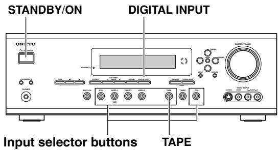
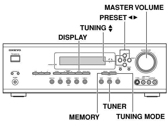
Front & Rear Panels
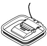
Front Panel
For detailed information, refer to the pages in parenthesis.
① STANDBY/ON button (31)
This button is used to set the HT-R520 to On or Standby.
② STANDBY indicator (31)
This indicator lights up when the HT-R520 is in Standby mode, and it flashes while a signal is being received from the remote controller.
③ STEREO button (39)
This button is used to select the Stereo listening mode.
④ LISTENING MODE [←] [▶] buttons (39)
These buttons are used to select the listening modes.
⑤ DISPLAY button (33)
This button is used to display various information about the currently selected source.
⑥ DIGITAL INPUT button (31, 45)
This button is used to assign the digital inputs and to specify the format of digital input signals.
⑦ Display
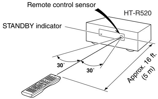
Remote control sensor (9)
This sensor receives control signals from the remote controller.
⑨ Arrow buttons
These buttons are used to select and adjust settings.
TUNING [▲] [▼] buttons
These buttons are used to tune into radio stations.
PRESET [ ] [ ] buttons
These buttons are used to select radio presets.
⑩ ENTER button
This button is used to confirm settings.
11 MASTER VOLUME control (32)
This control is used to set the volume of the HT-R520.
12 SPEAKER A & B buttons (32)
These buttons are used to turn speaker sets A and B on and off.
13 PHONES jack (37)
This 1/4-inch phone jack is for connecting a standard pair of stereo headphones for private listening.
14 TONE, [-] & [+] buttons (36)
These buttons are used to adjust the bass and treble.
15 MULTI CH button (33)
This button is used to select the multichannel DVD input.
16 Input selector buttons (31, 32, 43)
These buttons are used to select the input sources.
⑦ MEMORY button (34, 35)
This button is used to preset radio stations.
TUNING MODE button (34)
This button is used to select the Auto or Manual Tuning mode.
19 SETUP button
This button is used to access various settings.
RETURN button
This button is used to return to the previous screen when changing settings.
②VIDEO 3 INPUT (27)
These S-Video, composite video, and analog audio inputs can be used to connect a camcorder or games console.
Front & Rear Panels—Continued
Display
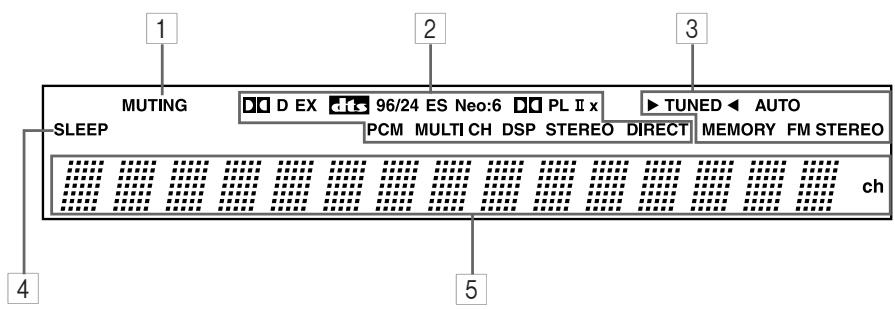
For detailed information, refer to the pages in parenthesis.
1 MUTING indicator (37)
This indicator flashes when the HT-R520 is muted.
2 Source/listening mode indicators (41)
These indicators show the currently selected listening mode and digital audio format.
3 Tuning indicators (34)
TUNED (34): This indicator lights up when the HT-R520 is tuned into a radio station.
AUTO (34): This indicator lights up when Auto Tuning is selected, and disappears when Manual Tuning is selected.
MEMORY (34): This indicator lights up when pre-setting radio stations.
FM STEREO (34): This indicator lights up when the HT-R520 is tuned to a stereo FM station.
4 SLEEP indicator (37)
This indicator lights up when the Sleep function has been set.
5 Message area
This area of the display shows various information about the currently selected source.
Front & Rear Panels—Continued
Rear Panel
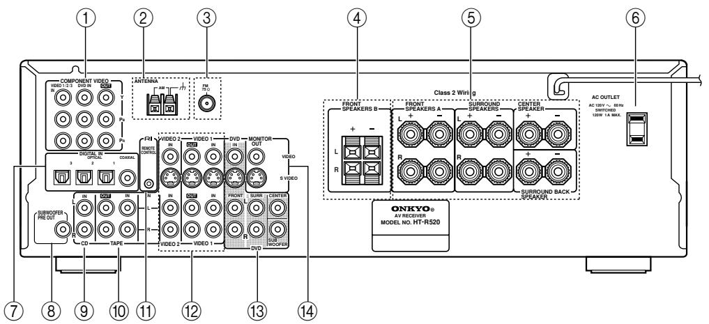
For detailed information, refer to the pages in parenthesis.
① COMPONENTVIDEO(20-23,26)
A DVD player, TV, or other component that supports component video can be connected here.
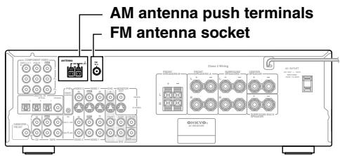
② AM ANTENNA (18, 19)
These push terminals are for connecting an AM antenna.
③ FM ANTENNA (18, 19)
This socket is for connecting an FM antenna.
④ FRONT SPEAKERS B (17)
These push terminals are for connecting speaker set B.
These terminal posts are for connecting speaker set A.
⑥ AC OUTLET (30)
This switched AC outlet can be used to supply power to another component. The connector type depends on the country in which you purchased your HT-R520.
⑦ DIGITAL IN OPTICAL 1, 2, 3 & COAXIAL (20-23, 25, 26, 28, 29)
These optical and coaxial sockets can be used to connect a CD, DVD, or LD (laser disc) player and other components with digital audio outputs.
SUBWOOFER PRE OUT (17)
A powered subwoofer can be connected here.
⑨ CD IN (28)
These analog inputs can be used to connect a CD player with analog outputs.
10 TAPE IN/OUT (28, 29, 31)
These analog inputs and outputs can be used to connect a cassette recorder, Mini Disc recorder, or other recorder with analog inputs and outputs.
⑪ RI (30)
This RI (Remote Interactive) socket can be connected to the RI socket on another Onkyo component. The HT-R520's remote controller can then be used to control that component. To use RI, you must make an analog audio connection (RCA) between the HT-R520 and the other component, even if they are connected digitally.
Note:
RI can only be used with Onkyo components.
⑫VIDEO 1 IN/OUT &VIDEO 2 IN (24, 25, 43)
The VIDEO 1 S-Video, composite video, and audio inputs and outputs can be used to connect a VCR.
The VIDEO 2 S-Video, composite video, and audio inputs can be used to connect another video source (e.g., cable TV, satellite TV, or a set-top box).
⑬ DVD IN/MULTI CH INPUT (23, 24)
The FRONT, SURR, CENTER, and SUBWOOFER inputs can be used to connect components with multiple analog audio outputs, including DVD players with individual 5.1-channel analog outputs. The S-Video or composite video input should be connected to a video output on the DVD player.
14 MONITOR OUT (21, 22)
The S-Video or composite video output should be connected to a video input on your TV or projector.
Before Using the HT-R520
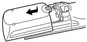
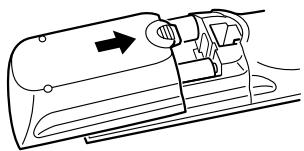
Installing the Batteries
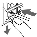
1 To open the battery compartment, press the small hollow and slide off the cover.
2 Insert the two supplied batteries (AA/R6) in accordance with the polarity diagram inside the battery compartment.
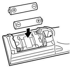
3 Put the cover onto the remote controller and slide it shut.
Notes:
- The batteries should last for about six months, although this will vary with usage.
- If the remote controller doesn't work reliably, try replacing the batteries.
- Don't mix new and old batteries or different types of batteries.
- If you intend not to use the remote controller for a long time, remove the batteries to prevent damage from leakage or corrosion.
- Expired batteries should be removed as soon as possible to prevent damage from leakage or corrosion.
Using the Remote Controller
To use the remote controller, point it at the HT-R520's remote control sensor, as shown below.
Notes:
- The remote controller may not work reliably if the HT-R520 is subjected to bright light, such as direct sunlight or inverter-type fluorescent lights. Keep this in mind when installing.
- If another remote controller of the same type is used in the same room, or the HT-R520 is installed close to equipment that uses infrared rays, the remote controller may not work reliably.
- Don't put anything, such as a book, on the remote controller, because the buttons may be pressed inadvertently, thereby draining the batteries.
- The remote controller may not work reliably if the HT-R520 is installed in a rack behind colored glass doors. Keep this in mind when installing.
- The remote controller will not work if there's an obstacle between it and the HT-R520's remote control sensor.
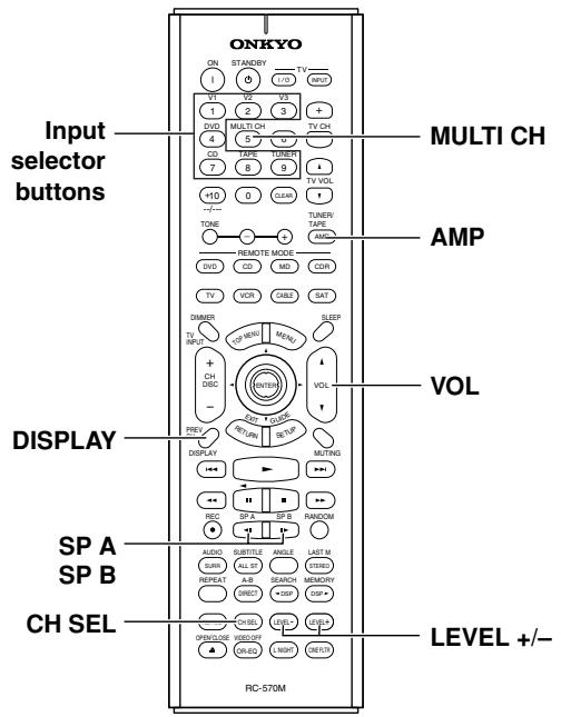
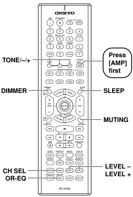
Remote Controller
How to Use the Remote Controller
Including the HT-R520, the remote controller can be used to control up to 10 different components, including Onkyo components connected via RI. The remote controller has a specific operating mode for use with each type of component. Modes are selected by using the nine REMOTE MODE buttons.
■ AMP/TUNER & TAPE Mode
TUNER/
TAPE
AMP
In AMP/TUNER & TAPE mode you can control the HT-R520 and an Onkyo cassette recorder connected via RI.
DVD, CD, MD & CDR Modes
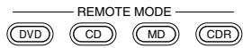
With these modes you can control an Onkyo DVD player, CD player, MiniDisc recorder, or CD recorder connected via RI (the remote controller should be pointed at the HT-R520). By entering the appropriate remote control code, the DVD mode can also be used to control another manufacturer's DVD player and the [CD], [MD], and [CDR] mode buttons can also be used with other manufacturer's components (e.g., DVD, TV, VCR, satellite or cable receiver). (See page 50.)
TV, VCR, CABLE & SAT Modes

With these modes you can control a TV, VCR, cable receiver, and satellite receiver. You must enter the appropriate remote control code first (see page 50).
1 Use the REMOTE MODE—[AMP], [DVD], [CD], [MD], [CDR], [TV], [VCR], [CABLE], [SAT]—buttons to select the modes.
2 Uses the buttons supported by that mode to control the component.
AMP/TUNER mode see page 10
DVD mode see page 12
CD mode see page 13
MD/CDR mode see page 14
TAPE mode see page 15
TV mode see page 55
see page 15 for TV
control buttons
VCR/CABLE/SAT mode see page 55
Note:
- Some of the functions described in this manual may not work as expected with other components.
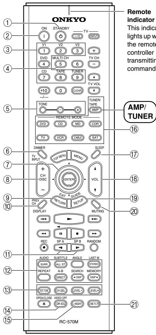
AMP/TUNER Mode
AMP/TUNER mode is used to control the HT-R520. To select AMP/TUNER mode, press the [AMP] mode button.
Remote Controller—Continued
For detailed information, refer to the pages in parenthesis.
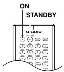
① STANDBY button (31)
This button is used to set the HT-R520 to Standby.
② ON button (31)
This button is used to turn on the HT-R520.
③ Input selector buttons (32)
These buttons are used to select the input sources.
④ MULTI CH button (33)
This button is used to select the multichannel DVD input.
⑤ TONE, [-] & [+] buttons (36)
These buttons are used to adjust the bass and treble.
⑥ DIMMER button (36)
This button is used to adjust the display brightness.
⑦ Arrow [▲]/[▼]/[▲]/[▶] & ENTER button
This button is used to select and adjust settings.
CH +/- button (35)
This button is used to select radio presets.
⑨ RETURN button
This button is used to return to the previous screen when changing settings.
10 DISPLAY button (33, 35)
This button is used to display various information about the currently selected input source.
⑪ SP A & SP B buttons (32)
These buttons are used to turn on and off speaker sets A and B.
⑫ Listening mode buttons (40)
SURR button
This button is used to select the Dolby and DTS listening modes.
ALL ST button
This button is used to select the All Ch Stereo listening mode.
STEREO button
This button is used to select the Stereo listening mode.
DIRECT button
This button is used to select the Direct listening mode.
[DSP] & [DSP▶] buttons
These buttons are used to select the Onkyo original DSP (digital signal processor) listening modes.
TEST TONE, CH SEL, LEVEL- & LEVEL+ buttons
These buttons are used to adjust the level of each speaker individually.
14 OR-EQ button (36)
This button is used to turn on the OptiResponse equalizer, which optimizes performance when the HT-R520 is used with the speakers included in the HTP-520 Home Theater Speaker Package. When the OptiResponse equalizer is on, you can enjoy a powerful sound with movies or music.
L NIGHT button (44)
This button is used to set the Late Night function.
16 REMOTE MODE buttons (10)
These buttons are used to select the remote controller modes. When you use the remote controller, the mode button for the currently selected mode lights up.
⑰ SLEEP button (37)
This button is used to set the Sleep function.
18 VOL button (32)
This button is used to set the volume of the HT-R520.
19 SETUP button (48, 49)
This button is used to access various settings.
20 MUTING button (37)
This button is used to mute the HT-R520.
② CINE FLTR button (44)
This button is used to set the CinemaFILTER function.
Remote Controller—Continued
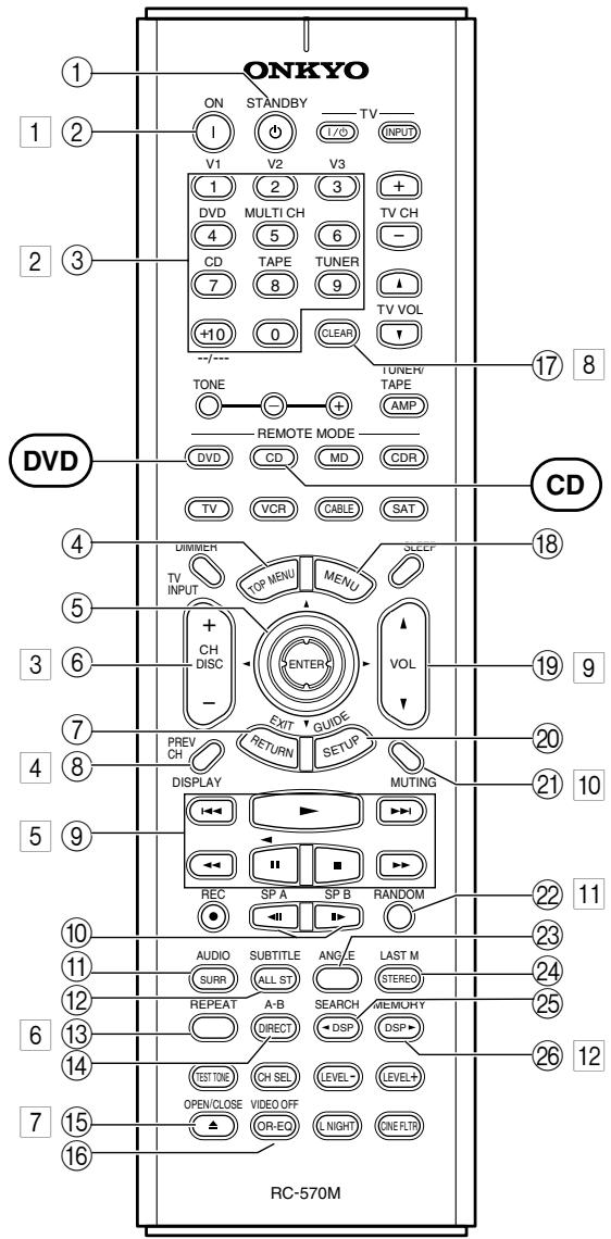
DVD Mode
DVD mode is used to control an Onkyo DVD player connected to the HT-R520 via R1.
To set the remote controller to DVD mode, press the [DVD] mode button.
Before selecting DVD mode and starting playback, you should press the [AMP] mode button followed by the [DVD] input selector button to select your DVD player as the input source.
① STANDBY button
This button is used to set the DVD player to Standby.
② ON button
This button is used to turn on the DVD player and set it to Standby.
③ Number buttons
These buttons are used to enter title, chapter, and track numbers and to enter times for locating specific points in time.
(4) TOP MENU button
This button is used to select a DVD's top menu.
⑤ Arrow [▲]/[▼]/[▲]/[▶] & ENTER button
This button is used to navigate DVD menus and the DVD player's onscreen setup menus.
⑥ DISC +/- button
This button selects discs on a DVD changer.
⑦ RETURN/EXIT button
This button is used to exit the DVD player's onscreen setup menu and to restart menu playback.
⑧ DISPLAY button
This button is used to display information about the current disc, title, chapter, or track on the DVD player's display, including the elapsed time, remaining time, total time, and so on.
⑨ Playback buttons
From left to right: Previous, Play, Next, Fast Reverse, Pause, Stop, and Fast Forward.
Step & Slow [←II] [/II] buttons
These buttons are used for frame-by-frame playback and slow-motion playback.
⑪ AUDIO button
This button is used to select foreign language soundtracks and audio formats (e.g., Dolby Digital or DTS).
12 SUBTITLE button
This button is used to select subtitles.
13 REPEAT button
This button is used to set the repeat playback functions.
Remote Controller—Continued
14 A-B button
This button is used to set the A-B repeat playback function.
15 OPEN/CLOSE [▲] button
This button is used to open and close the disc tray.
16VIDEO OFF button
This button is used to turn off the internal video circuitry, eliminating the possibility of interference when playing audio-only discs.
⑰ CLEAR button
This button is used to cancel functions and to clear entered numbers.
18 MENU button
This button is used to display a DVD's menu.
19 VOL button
This button is used to set the volume of the HT-R520.
SETUP/GUIDEButton
This button is used to access the DVD player's onscreen setup menus.
② MUTING button
This button is used to mute the HT-R520.
2 RANDOM button
This button is used with the random playback function.
ANGLE button
This button is used to select different camera angles.
24 LAST M button
This button is used with the last memory function, which allows you to resume DVD playback from where you left off.
25 SEARCH button
This button is used to search for titles, chapters, tracks, and specific points in time.
26 MEMORY button
This button is used with the memory playback function, which allows you to create a custom playlist of titles, chapters, or tracks.
CD Mode
CD mode is used to control an Onkyo CD player connected to the HT-R520 via RI.
To set the remote controller to CD mode, press the [CD] mode button.
Before selecting CD mode and starting playback, you should press the [AMP] mode button followed by the [CD] input selector button to select your CD player as the input source.
1 ON button
This button is used to set the CD player to On or Standby.
Number buttons
These buttons are used to enter track numbers and to enter times for locating specific points in time.
3 DISC button
This button is used to select discs on a CD changer.
4 DISPLAY button
This button is used to display information about the current disc or track on the CD player's display, including the elapsed time, remaining time, total time, and so on.
5 Playback buttons
From left to right: Previous, Play, Next, Fast Reverse, Pause, Stop, and Fast Forward.
6 REPEAT button
This button is used to set the repeat playback functions.
7 OPEN/CLOSE [▲] button
This button is used to open and close the disc tray.
8 CLEAR button
This button is used to cancel functions and to clear entered numbers.
9 VOL button
This button is used to set the volume of the HT-R520.
10 MUTING button
This button is used to mute the HT-R520.
11 RANDOM button
This button is used with the random playback function.
12 MEMORY button
This button is used with the memory playback function, which allows you to create a custom playlist of tracks.
Remote Controller—Continued
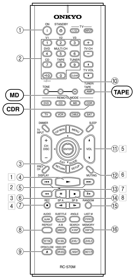
MD Mode & CDR Mode
MD mode is used to control an Onkyo MiniDisc recorder connected to the HT-R520 via RI. CDR mode is used to control an Onkyo CD recorder connected to the HT-R520 via RI.
To select MD mode, press the [MD] mode button. To select CDR mode, press the [CDR] mode button.
Before selecting MD or CDR mode and starting playback, you should press the [AMP] mode button followed by the [TAPE] input selector button to select your MiniDisc or CD recorder as the input source.
① ON button
This button is used to set the MiniDisc recorder or CD recorder to On or Standby.
② Number buttons
These buttons are used to enter track numbers and to enter times for locating specific points in time.
③ DISPLAY button
This button is used to display information about the current disc or track on the MD/CDR recorder's display, including the elapsed time, remaining time, total time, and so on.
④ Play [▶] button
This button is used to start playback.
⑤ Previous & Next [▶]按钮
The Previous [▶] button is used to select the previous track. During playback it selects the beginning of the current track. The Next [▶] button is used to select the next track.
⑥ Pause [I] button
This button is used to pause playback.
⑦ REC [●] button
This button is used to start recording.
⑧ REPEAT button
This button is used to set the repeat playback functions.
⑨ OPEN/CLOSE [▲] button
This button is used to eject the MiniDisc or open and close the disc tray of the CD recorder.
10 CLEAR button
This button is used to cancel functions and to clear entered numbers.
VOL button
This button is used to set the volume of the HT-R520.
12 MUTING button
This button is used to mute the HT-R520.
Remote Controller—Continued
⑬ FR & FF [/▶] buttons
The FR [] button is used to start fast reverse. The FF [ ] button is used to start fast forward.
14 Stop [■] button
This button is used to stop playback.
15 RANDOM button
This button is used with the random playback function.
16 MEMORY button
This button is used with the memory playback function, which allows you to create a custom playlist of tracks.
Tape Mode
Tape mode is used to control an Onkyo cassette recorder connected to the HT-R520 via RI.
To set the remote controller to Tape mode, press the [AMP] mode button.
Before selecting TAPE mode and starting playback, you should press the [AMP] mode button followed by the [TAPE] input selector button to select your cassette recorder as the input
For double cassette decks, only Deck B can be controlled.
1 Play [▶] button
This button is used to start playback.
Previous & Next [▶]按钮
The Previous [ ] button is used to select the previous track. During playback it selects the beginning of the current track. The Next [ ] button is used to select the next track.
The Previous and Next [| ] / [| ] buttons may not work properly with some cassette tapes depending on how they were recorded.
3 Reverse Play [<] button
This button is used to start reverse playback.
4REC[●]button
This button is used to start recording.
5 VOL button
This button is used to set the volume of the HT-R520.
6 MUTING button
This button is used to mute the HT-R520.
7 Rewind & FF [] / [] buttons
The Rewind [] button is used to start rewind. The FF [ ] button is used to start fast forward.
8 Stop [■] button
This button is used to stop playback.
TV Control Buttons
The remote controller has dedicated buttons for controlling a TV, which can be used regardless of which remote controller mode is currently selected. To use these buttons, you must first program the [TV] mode button with the appropriate remote control code for your TV (see page 50).
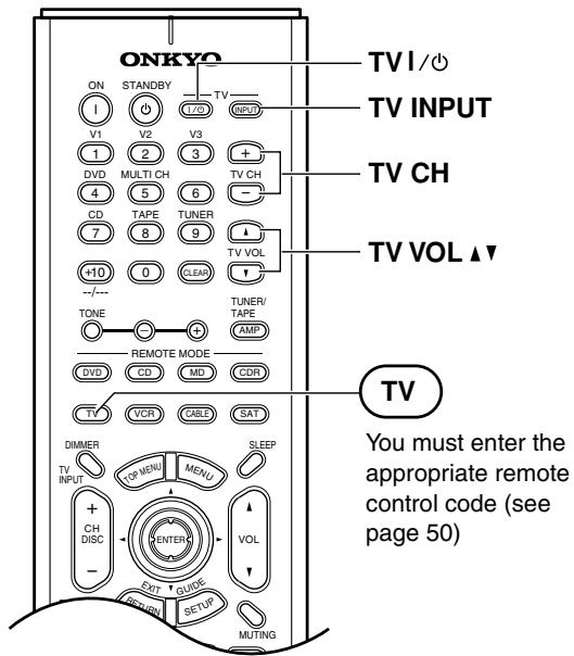
| TV [∘/ɪ] | Set the TV to On or Standby |
| TV CH [+]/[−] | Selects channels on the TV |
| [TV INPUT] | Selects the TV's VCR input |
| TV VOL [▲]/[▼] | Adjusts the TV's volume |
Connecting Your Speakers
Enjoying Home Theater
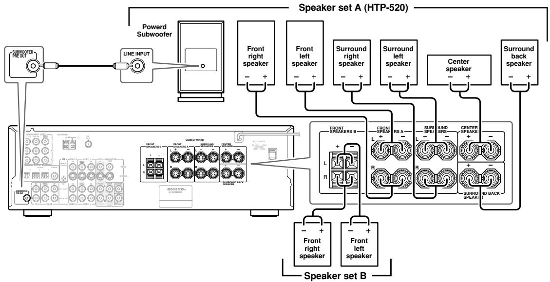
You can use two sets of speakers with the HT-R520: speaker set A and speaker set B.
Speaker set A (HTP-520) should be installed in your main listening room and can be used with Dolby Digital and DTS surround material. Each speaker must be positioned at a specific location in your listening room to get the best from surround sound material. The following illustration shows the best positions for your surround-sound speakers.
Speaker set B can be installed in another room and used with stereo and mono material. Speakers can be positioned in the standard position for stereo speakers or however you like.
Front left and right speakers
These output the overall sound. Their role in a home theater is to provide a solid anchor for the sound image. They should be positioned facing the listener at about ear level, and equidistant from the TV. Angle them inward so as to create a triangle, with the listener at the apex.
Surround back speaker
This speaker further enhances the realism of surround sound and improves sound localization behind the listener. Position it behind the listener about 2-3 feet (60-100 cm) above ear level. Make sure that the listening position is within the range of the speaker.
Center speaker
This speaker enhances the front left and right speakers, making sound movements distinct and providing a full sound image. In movies it's used mainly for dialog.
Position it close to your TV (preferably on top) facing forward at about ear level, or at the same height as the front left and right speakers.
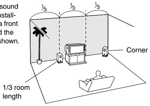
Subwoofer
The subwoofer handles the bass sounds of the LFE (Low-Frequency Effects) channel. The volume and quality of the bass output from your subwoofer will depend on its position, the shape of your listening room, and
your listening position. In general, a good bass sound can be obtained by installing the subwoofer in a front corner, or at one-third the width of the wall, as shown.
Surround left and right speakers
These speakers are used for precise sound positioning and to add realistic ambience.
Position them at the sides of the listener, or slightly behind, about 2-3 feet (60-100 cm) above ear level. Ideally they should be equidistant from the listener.
Speaker Configuration
To get the very best from your surround-sound system, you should also specify the distance between the listener and each individual speaker so that the sound from each speaker arrives at the listener's ears at the same time (see page 46). In addition, you should set the level of each individual speaker to achieve an equal balance (see page 47.)
Connecting Your Speakers—Continued
Connecting Your Speakers
Before you connect your speakers, read the following:
- Disconnect the power cord from the wall outlet.
- Read the instructions supplied with your speakers.
- Pay close attention to speaker wiring polarity. In other words, connect positive (+) terminals only to positive (+) terminals, and negative (-) terminals only to negative (-) terminals. If you get them the wrong way around, the sound will be out of phase and will sound odd.
- Only use speakers with an impedance of 8 ohms or higher. Connecting speakers with an impedance of less than 8 ohms may damage the HT-R520.
- Unnecessarily long or very thin speaker cables may affect the sound quality and should be avoided.
- Be careful not to short the positive and negative connections. Doing so may damage the HT-R520.
- Don't connect more than one cable to each speaker terminal. Doing so may damage the HT-R520.
- If you want to connect a single speaker instead of a pair, connect it to either the left or right speaker terminals, not both.
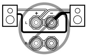
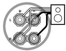
Connecting speaker Set A
The HT-R520's positive (+) speaker terminals are color-coded for ease of identification. (The negative (-) speaker terminals are all black.)
| Speaker terminal | Color |
| Front left | White |
| Front right | Red |
| Center | Green |
| Speaker terminal | Color |
| Surround left | Blue |
| Surround right | Gray |
| Surround back | Brown |
1 Unscrew the terminal. Fully insert the wire. Screw the terminal tight.
Connecting Speaker Set B
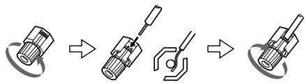
1 Strip 3 / 8'' (10 mm) of insulation from the ends of the speaker cables, and twist the bare wires tightly, as shown.
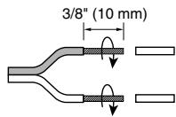
2 While pressing the lever, insert the wire into the hole, and then release the lever. Make sure that the terminals are gripping the bare wires, not the insulation.
The following illustration shows which speakers should be connected to which terminals.
Connecting Antenna
Connecting Antenna
This chapter explains how to connect the supplied indoor FM antenna and AM loop antenna and how to connect commercially available outdoor FM and AM antennas. The HT-R520 won't pick up any radio signals without any antenna connected, so you must connect the antenna to use the tuner.
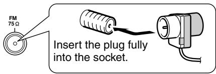
Connecting the Indoor FM Antenna
The supplied indoor FM antenna is for indoor use only.
1 Attach the FM antenna, as shown.
Once the HT-R520 is ready for use, you'll need to tune into an FM radio station and adjust the position of the FM antenna to achieve the best possible reception.
2 Use thumbtacks or something similar to fix the FM antenna into position.
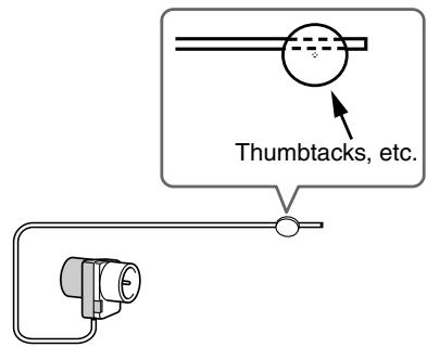
Caution: Be careful that you don't injure yourself when using thumbtacks.
If you cannot achieve good reception with the supplied indoor FM antenna, try a commercially available outdoor FM antenna instead (see page 19).
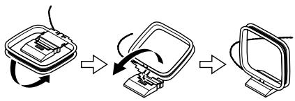
Connecting the AM Loop Antenna
The supplied indoor AM loop antenna is for indoor use only.
1 Assemble the AM loop antenna, inserting the tabs into the base, as shown.
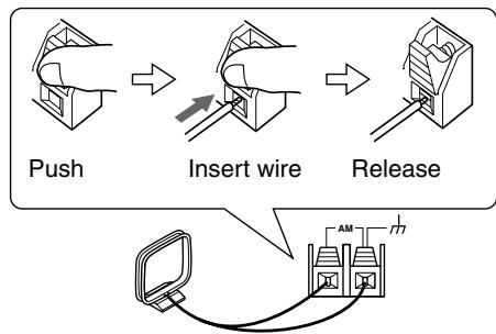
2 Connect both wires of the AM loop antenna to the AM push terminals, as shown.
(The antenna's wires are not polarity sensitive, so they can be connected either way around.)
Make sure that the wires are attached securely and that the push terminals are gripping the bare wires, not the insulation.
Once the HT-R520 is ready for use, you'll need to tune into an AM radio station and adjust the position of the AM antenna to achieve the best possible reception.
Keep the antenna as far away as possible from the HT-R520, TV, speaker cables, and power cords.
If you cannot achieve good reception with the supplied indoor AM loop antenna, try using it with a commercially available outdoor AM antenna (see page 19).
Connecting Antenna—Continued
Connecting an Outdoor FM Antenna
If you cannot achieve good reception with the supplied indoor FM antenna, try a commercially available outdoor FM antenna instead.
Notes:
- Outdoor FM antennas work best outside, but usable results can sometimes be obtained when installed in an attic or loft.
- For best results, install the outdoor FM antenna well away from tall buildings, preferably with a clear line of sight to the transmitter.
- Outdoor antenna should be located away from possible noise sources, such as neon signs, busy roads, etc.
- For safety reasons, outdoor antenna should be situated well away from power lines and other high-voltage equipment.
- Outdoor antenna must be grounded in accordance with local regulations to prevent electrical shock hazards.
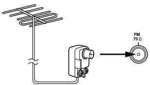
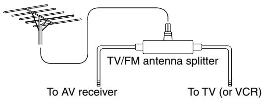
Using a TV/FM Antenna Splitter
It's best not to use the same antenna for both FM and TV reception, as this can cause interference problems. If circumstances demand it, use a TV/FM antenna splitter, as shown.
Connecting an Outdoor AM Antenna
If good reception cannot be achieved using the supplied AM loop antenna, an outdoor AM antenna can be used in addition to the loop antenna, as shown.
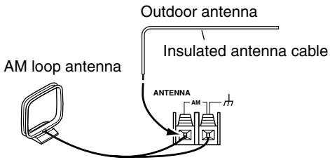
Outdoor AM antennas work best when installed horizontally outside, but good results can sometimes be obtained indoors by mounting horizontally above a window. Note that the AM loop antenna should be left connected.
Outdoor antenna must be grounded in accordance with local regulations to prevent electrical shock hazards.
Connecting the HT-R520
Before Making Any Connections
- Read the manuals supplied with your AV components.
- Don't connect the power cord until you've completed and double-checked all audio and video connections.
Optical Digital Inputs
The HT-R520's optical digital inputs have shutter-type covers that open when an optical plug is inserted and close when it's removed. Push plugs in all the way.
Caution: To prevent shutter damage, hold the optical plug straight when inserting and removing.
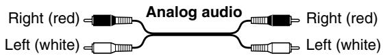
RCA AV Connection Color Coding
RCA-type AV connections are usually color coded: red, white, and yellow. Use red plugs to connect right-channel audio inputs and outputs (typically labeled “R”). Use white plugs to connect left-channel audio inputs and outputs (typically labeled “L”). And use yellow plugs to connect composite video inputs and outputs.

- Push plugs in all the way to make good connections (loose connections can cause noise or malfunctions).
- To prevent interference, keep audio and video cables away from power cords and speaker cables.

AV Cables & Sockets
Video
| Cable | Socket | Description | |
| Component video cable | YPBPRPRPR | YPBPRPR | Component video separates the luminance (Y) and color difference signals (PR, PB), providing the best picture quality. (Some TV manufacturers label their component video sockets slightly differently.) |
| S-Video cable | SVIDEO | SVIDEO | S-Video separates the luminance and color signals and provides better picture quality than composite video. |
| Composite video cable | VIDEO | VIDEO | Composite video is commonly used on TVs, VCRs, and other video equipment. Use only dedicated composite video cables. |
Audio
| Cable | Socket | Description | |
| Optical digital audio cable | OPTICAL | Offers the best sound quality and allows you to enjoy surround sound (e.g., Dolby Digital, DTS). The audio quality is the same as for coaxial. | |
| Coaxial digital audio cable | COAXIAL | Offers the best sound quality and allows you to enjoy surround sound (e.g., Dolby Digital, DTS). The audio quality is the same as for optical. | |
| Analog audio cable (RCA) | L-R- | This cable carries analog audio. It's the most common connection format for analog audio, and can be found on virtually all AV components. | |
| Multichannel analog audio cable (RCA) | FRONT SURR CENTER DVD | This cable carries multichannel analog audio and it's typically used to connect DVD players with individual 5.1-channel analog audio outputs. Several standard analog audio cables can be used instead of a multichannel cable. | |
Connecting the HT-R520—Continued
Connection Guide
Inputs
Up to five AV components can be connected to the HT-R520's rear panel inputs, and one to its front panel input. The following table lists the type of component that you can connect to each input.
| Input | Type of component you can connect | Page # for more info. |
| DVD | DVD player, etc. | 23 |
| VIDEO1 | VCR, etc. | 24 |
| VIDEO2 | TV, satellite receiver, cable receiver, set-top box, LD player, etc. | 22 (for TV con-nections) 26 |
| CD | CD player, etc. | 28 |
| TAPE | Cassette recorder, DAT, CD recorder, MiniDisc recorder, turntable, etc. | 28, 29 |
| VIDEO3 | Camcorder, games console, etc. | 27 |
Outputs (for recording)
The HT-R520 has two outputs for recording. The following table lists the type of component that you can connect to each output.
| Output | Type of component you can connect | Page # for more info. |
| VIDEO1 | VCR, etc. | 25 |
| TAPE | Cassette recorder, DAT, CD recorder, MiniDisc recorder, etc. | 28, 29 |
■ MONITOR OUT
Video signals received by the video inputs are output by the MONITOR OUT sockets for display on the connected TV or projector.
The HT-R520 has three types of video output: composite video, S-Video, and component video. Connect the appropriate output to your TV or projector (see page 22).
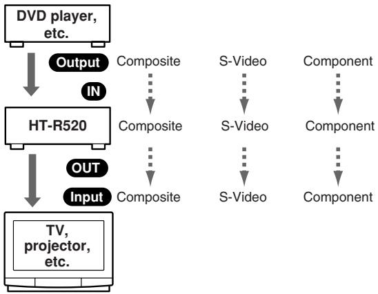
Which Connections Should I Use?
The HT-R520 offers several interconnection formats for compatibility with a wide range of AV equipment. The format you choose will depend on the formats supported by your other components. Use the following sections as a guide.
For video equipment you need to use two cables—one for video, one for audio.
Video Connection Formats
Video equipment can be connected to the HT-R520 using one of the following video connection formats: composite video, S-Video, or component video, the latter offering the best picture quality.
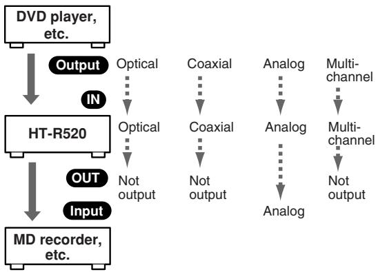
When choosing a connection format, bear in mind that the HT-R520 doesn't convert between formats, so only outputs of the same format as the input will output the signal.
For example, if you connect your DVD player to the S-VIDEO DVD IN, a video signal will be output by the S-VIDEO MONITOR OUT (for your TV) and the S-VIDEO VIDEO 1 OUT (for your VCR), but not by any composite video or component video outputs.
Audio Connection Formats
Audio equipment can be connected to the HT-R520 using the following audio connection formats: analog, optical, coaxial, and multichannel.
When choosing a connection format, bear in mind that the HT-R520 doesn't convert between formats.
For example, audio signals connected to an OPTICAL or COAXIAL digital input are not output by the analog TAPE OUT, so if you want to record from, for example, your CD player, in addition to connecting it to a digital input, you must also connect it to the analog CD IN.
Connecting Your TV or Projector
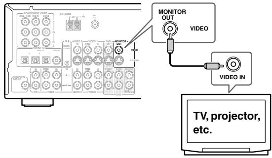
Monitor Out
Using Composite Video
Use a composite video cable to connect the HT-R520's VIDEO MONITOR OUT to a composite video input on your TV, as shown.
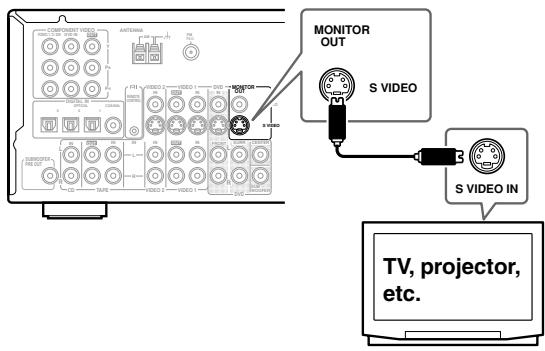
Using S-Video
Use an S-Video cable to connect the HT-R520's SVIDEO MONITOR OUT to an S-Video input on your TV, as shown.
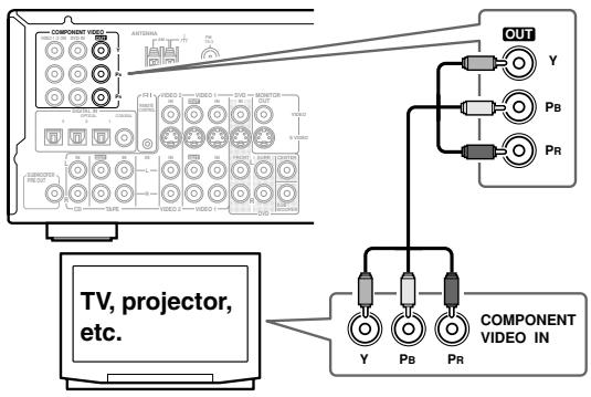
Using Component Video
Use a component video cable to connect the HT-R520's COMPONENTVIDEO OUT to a component video input on your TV, as shown.
Audio Connections
The following connections will allow you to listen to audio from your TV via the HT-R520. If your TV has no audio outputs, connect the HT-R520 to your VCR and use its tuner (see page 24).
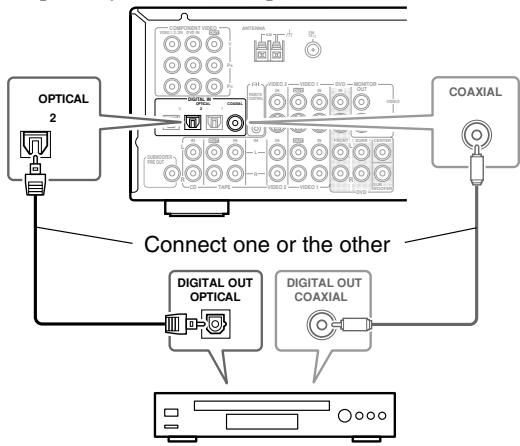
Using a Coaxial or Optical Connection
- Use an optical digital audio cable to connect the HT-R520's DIGITAL IN OPTICAL 2 to the optical output on your TV, as shown.
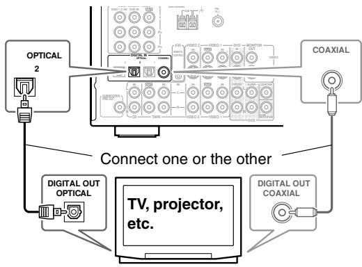
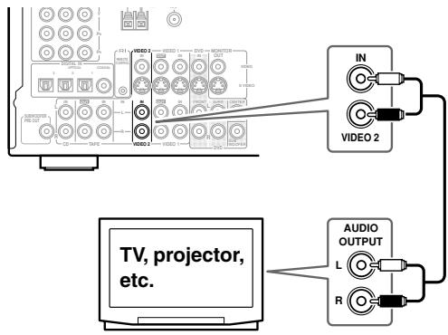
Using Analog Connections
If your TV doesn't have digital audio outputs, or you want to record from it, you'll need to make the following analog audio connections.
Use an analog audio cable to connect the HT-R520's VIDEO 2 IN L/R inputs to the analog audio outputs on your TV, as shown.
Connecting the HT-R520—Continued
Connecting a DVD player
Video Connections
You only need to use one of the following video connection methods.
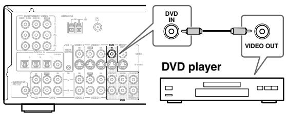
Using Composite Video
Use a composite video cable to connect the HT-R520's VIDEO DVD IN to the composite video output on your DVD player, as shown.
- Your TV must also be connected via composite video.
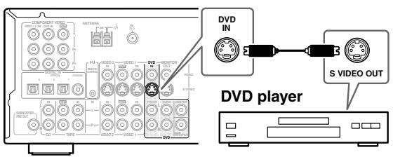
Using S-Video
Use an S-Video cable to connect the HT-R520's SVIDEO DVD IN to the S-Video output on your DVD player, as shown.
- Your TV must also be connected via S-Video.
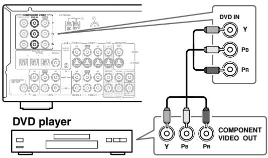
Using Component Video
Use a component video cable to connect the HT-R520's COMPONENT VIDEO DVD IN to the component video output on your DVD player, as shown.
- Your TV must also be connected via component video.
Audio Connections
Note:
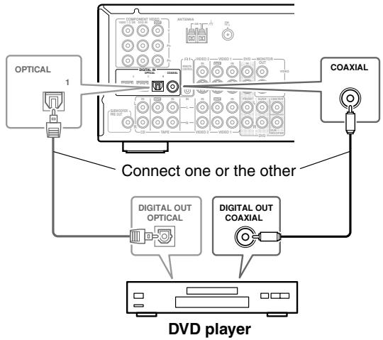
Initially, the COAXIAL digital input is assigned to the DVD input source. If you connect your DVD player to a different digital input or only to an analog input, you'll need to assign it to the DVD input source (see page 31).
Using a Coaxial or Optical Connection
- Use a coaxial digital audio cable to connect the HT-R520's DIGITAL IN COAXIAL to the coaxial output on your DVD player, as shown.
OR
- Use an optical digital audio cable to connect the HT-R520's DIGITAL IN OPTICAL 1 to the optical output on your DVD player, as shown.
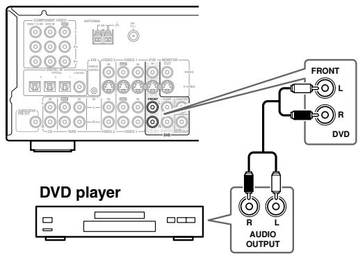
Using Analog Connections
Even if your DVD player is connected digitally (coaxial or optical), to use R1, or to record audio from your DVD player, you'll need to make analog connections as well.
Use an analog audio cable to connect the HT-R520's FRONT DVD IN to the analog audio outputs on your DVD player, as shown.
If your DVD player has left, right, and multichannel outputs, be sure to use the left and right outputs.
Connecting the HT-R520—Continued
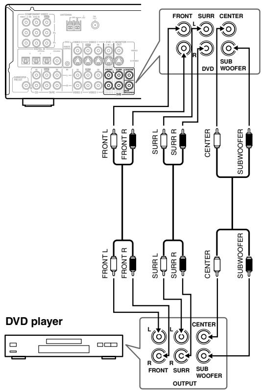
DVD Multichannel Connection
If your player supports multichannel audio formats such as DVD-Audio and Super Audio CD, and it has multi-channel analog audio outputs, you can enjoy DVD-Audio and Super Audio CD playback. Use a multichannel analog audio cable to connect the HT-R520's MULTI CH INPUT FRONT, SUB-WOOFER, CENTER, and SURR sockets to the 5.1-channel analog audio outputs on your DVD player, as shown. Alternatively, use three standard analog audio cables.
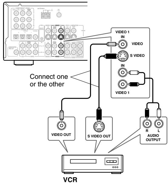
Connecting a VCR for Playback
You can watch videos by connecting your VCR to the HT-R520.
By using your VCR's tuner, this connection example allows you to listen to the sound from your favorite TV programs through the HT-R520. This is useful if your TV has no audio outputs.
Video Connections
- Use an S-Video cable to connect the HT-R520's SVIDEOVIDEO 1 IN to the S-Video output on your VCR, as shown.
OR
- Use a composite video cable to connect the HT-R520's VIDEOVIDEO 1 IN to a composite video output on your VCR, as shown.
An S-Video connection provides better picture quality than a composite video connection.
Audio Connections
- Use an analog audio cable to connect the HT-R520's VIDEO 1 IN L/R inputs to the analog audio outputs on your VCR, as shown.
Connecting the HT-R520—Continued
Connecting a VCR for Recording
Video Connections
- Use an S-Video cable to connect the HT-R520's SVIDEOVIDEO 1 OUT to an S-Video input on your recording VCR.
OR
- Use a composite video cable to connect the HT-R520's VIDEOVIDEO 1 OUT to a composite video input on your recording VCR.
Audio Connections
- Use an analog audio cable to connect the HT-R520's AUDIOVIDEO 1 L/R OUTs to the audio inputs on your recording VCR.
This illustration shows how to connect a VCR for recording from a TV or another VCR.

Notes:
- The HT-R520 must be turned on for recording. Recording is not possible while it's in Standby mode.
- If you want to record directly from your TV or playback VCR without going through the HT-R520, connect your TV/VCR's audio and video outputs directly to your recording VCR's AV inputs. See the manuals supplied with your TV and VCR for details.
- Video signals connected to composite video inputs can only be recorded via composite video outputs. If your TV and video playback components are connected via composite video, you must connect your recording VCR via composite video as well. Similarly, video signals connected to S-Video inputs can only be recorded via S-Video outputs. If your TV and video playback components are connected via S-Video, you must connect your recording VCR via S-Video as well.
Connecting the HT-R520—Continued
Connecting Other Video Sources—Satellite, Cable, Set-top box, LD Player, etc.
Video Connections
You only need to use one of the following video connection methods.
Using Composite Video
Use a composite video cable to connect the HT-R520's VIDEO 2 IN to the composite video output on your video component, as shown.
- Your TV must also be connected via composite video.
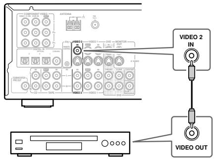
Satellite, cable, set-top box, LD player, etc.
Using S-Video
Use an S-Video cable to connect the HT-R520's SVIDEO 2 IN to the S-Video output on your video component, as shown.
- Your TV must also be connected via S-Video.
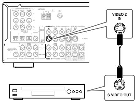
Satellite, cable, set-top box, LD player, etc.
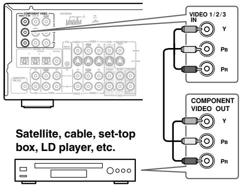
Using Component Video
Use a component video cable to connect the HT-R520's COMPONENTVIDEO1/2/3INto the component video output on your video component, as shown.
- Your TV must also be connected via component video.
Audio Connections
Notes:
- Initially, the VIDEO 2 input source is assigned to the OPTICAL 2 DIGITAL IN. If you connect to a different digital audio input, or you connect to only the analog VIDEO 2 input, you'll need to change the input assignment (see page 31).
- To connect an LD player with an AC-3RF output, you'll need a commercially available demodulator.
Using a Coaxial or Optical Connection
- Use an optical digital audio cable to connect the HT-R520's DIGITAL IN OPTICAL 2 to the optical output on your video component, as shown.
OR
- Use a coaxial digital audio cable to connect the HT-R520's DIGITAL IN COAXIAL to the coaxial output on your video component, as shown.
Satellite, cable, set-top box, LD player, etc.
Connecting the HT-R520—Continued
Using Analog Connections
If your video component doesn't have digital audio outputs, or you want to record from it, you'll need to make the following analog audio connections.
Use an analog audio cable to connect the HT-R520's VIDEO 2 IN L/R inputs to the analog audio outputs on your video component, as shown.
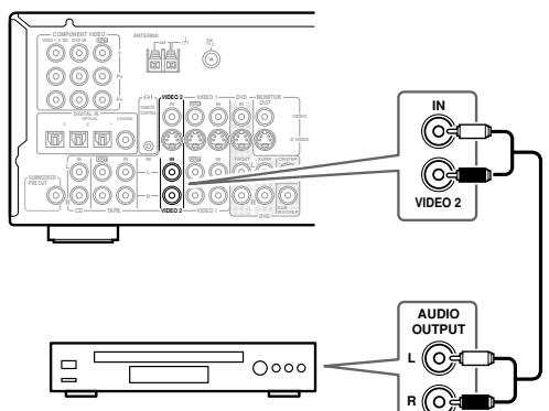
Satellite, cable, set-top box, LD player, etc.
Connecting a Camcorder, Games Console, etc.
Video Connections
You only need to use one of the following video connection methods.
Using S-Video
Use an S-Video cable to connect the HT-R520's VIDEO 3 INPUT SVIDEO input to the S-Video output on your camcorder, games console, etc., as shown.
- Your TV must also be connected via S-Video.
Using Composite Video
Use a composite video cable to connect the HT-R520's VIDEO 3 INPUT VIDEO input to the composite video output on your camcorder, games console, etc., as shown.
- Your TV must also be connected via composite video.
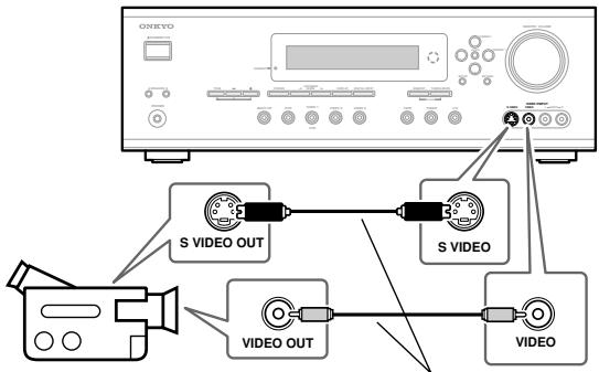
Camcorder, games console, etc.
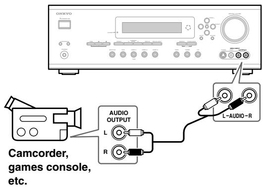
Audio Connections
Use an analog audio cable to connect the HT-R520's VIDEO 3 INPUT AUDIO L/R inputs to the analog audio outputs on your camcorder, games console, etc., as shown.
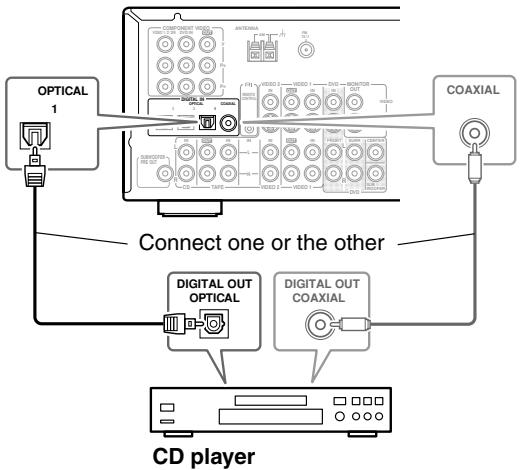
Connecting a CD Player
Note:
Initially, the CD input source is assigned to the OPTICAL 1 digital input. If you connect your CD player to a different digital input, or you connect it to only the analog CD IN, you'll need to change the input assignment (see page 31).
Using a Coaxial or Optical Connection
- Use an optical digital audio cable to connect the HT-R520's DIGITAL IN OPTICAL 1 to the optical output on your CD player, as shown.
OR
- Use a coaxial digital audio cable to connect the HT-R520's DIGITAL IN COAXIAL to the coaxial output on your CD player, as shown.
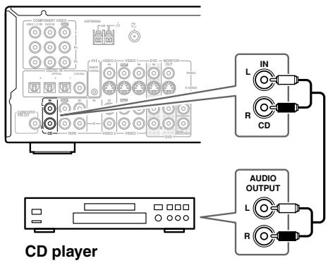
Using Analog Connections
Even if your CD player is connected digitally (coaxial or optical), to use R1, or to record audio from your CD player, you'll need to make analog audio connections as well.
Use an analog audio cable to connect the HT-R520's CD IN L/R inputs to the analog audio outputs on your CD player, as shown.
Connecting a Cassette Recorder
Use an analog audio cable to connect the HT-R520's TAPE IN L/R inputs to the cassette recorder's outputs, and use another analog audio cable to connect the HT-R520's TAPE OUT L/R outputs to the cassette recorder's inputs, as shown.
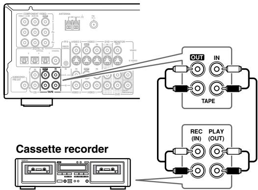
Note:
Initially, the TAPE input source is assigned to the OPTICAL 3 DIGITAL IN. If you connect your cassette recorder to only the analog TAPE IN, you'll need to set the TAPE input source to "----" (see page 31).
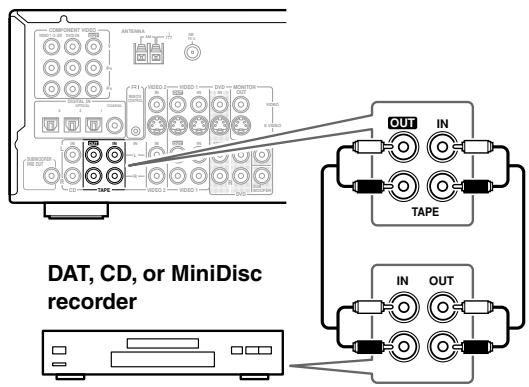
Connecting a DAT, CD, or MiniDisc Recorder
You can connect a DAT, CD, or MiniDisc recorder instead of a cassette recorder.
Note:
Initially, the TAPE input source is assigned to the OPTICAL 3 DIGITAL IN. If you connect your DAT, CD, or MiniDisc recorder to a different digital input, or you connect it to only the analog TAPE IN, you'll need to change the input assignment (see page 31).
Using Analog Connections
Use an analog audio cable to connect the HT-R520's TAPE IN L/R inputs to the recorder's outputs, and use another analog audio cable to connect the HT-R520's TAPE OUT L/R outputs to the recorder's inputs, as shown.
Connecting the HT-R520—Continued
Using a Coaxial or Optical Connection (playback only)
- Use an optical digital audio cable to connect the HT-R520's DIGITAL IN OPTICAL 3 to the optical output on your recorder, as shown.
OR
- Use a coaxial digital audio cable to connect the HT-R520's DIGITAL IN COAXIAL to the coaxial output on your recorder, as shown.
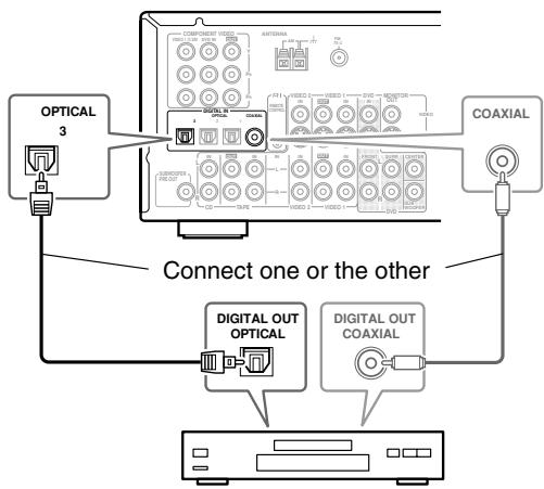
DAT, CD, or MiniDisc recorder
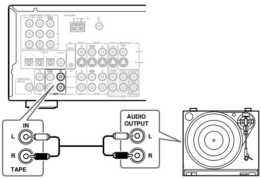
Connecting a Turntable
Note:
Initially, the TAPE input source is assigned to the OPTICAL 3 DIGITAL IN. If you connect your turntable to the analog TAPE IN, you'll need to set the TAPE input source to "----" (see page 31).
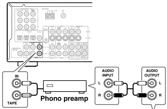
Turntable with a Built-in Phono Preamp
Use an analog audio cable to connect the HT-R520's TAPE IN L/R inputs to the audio outputs on your turntable, as shown.
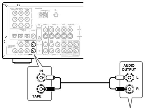
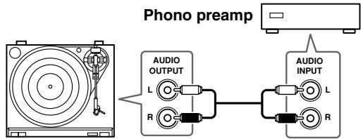
Turntable without a Built-in Phono Preamp
Use an analog audio cable to connect the HT-R520's TAPE IN L/R inputs to the audio outputs on your phono preamp, and use another analog audio cable to connect the phono preamp's inputs to your turntable, as shown.
Turntable with an MC (Moving Coil) Cartridge
Use an analog audio cable to connect the HT-R520's TAPE IN L/R inputs to the audio outputs on your phono preamp. Use another analog audio cable to connect the phono preamp's inputs to your MC head amp's outputs. And use another analog audio cable to connect the MC head amp's inputs to your turntable, as shown.
Connecting the HT-R520—Continued
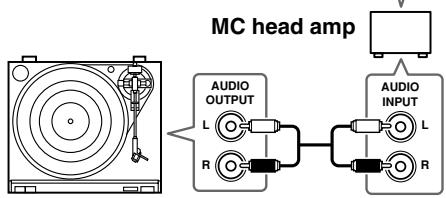
Connecting Onkyo R1 Components
To use R1, you must make an analog audio connection (RCA) between the HT-R520 and the other component, even if they are connected digitally.
With RI (Remote Interactive) you can control your RI-compatible Onkyo CD player, DVD player, and so on with the HT-R520's remote controller, and use the following special RI functions:
Auto Power On/Standby
When you start playback on a component connected via RI, if the HT-R520 is in Standby, it will turn on and select that component as the input source automatically. Similarly, when the HT-R520 is set to Standby, all components connected via RI also enter Standby. This function will not work if the component's power cord is connected to the HT-R520's AC OUTLET.
Direct Change
When playback is started on a component connected via RI, the HT-R520 automatically selects that component as the input source. If your DVD player is connected to the HT-R520's multichannel input, you must press the [MULTI CH] button to enjoy all channels (see page 33). This is because the Direct Change RI function only selects the FRONT DVD IN sockets.
Remote Control
You can use the HT-R520's remote controller to control other RL-compatible Onkyo components.
Notes:
- Push plugs in all the way to make good connections.
- Use only RI cables for RI connections. RI cables are supplied with Onkyo players (DVD, CD, etc.).
- Some components have two RI sockets, you can connect either one to the HT-R520. The other is for connecting additional RI-compatible components.
-
Connect the HT-R520's RI socket to only Onkyo components. Connecting to other manufacturer's components may cause them to malfunction.
-
Some components may not support all R1 functions. Refer to the manuals supplied with your components.
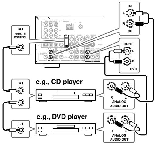
Connecting the Power Cords of Other Components
The HT-R520 has AC outlet on its rear panel for connecting the power cord of another AV component. The other component's power switch can be left in the ON position so that it turns on or off when the HT-R520 is set to On or Standby.
Caution:
- Make sure that the capacity of the component that you connect to the AC OUTLET does not exceed the stated capacity (e.g., 100 W).
Note:
- Onkyo components with RI sockets should be connected to regular wall outlets.
Connecting the Power Cord
Notes:
- Before connecting the power cord, connect all of your speakers and AV components.
- Turning on the HT-R520 may cause a momentary power surge that might interfere with other electrical equipment on the same circuit. If this is a problem, plug the HT-R520 into a different branch circuit.
Turning On & First Time Setup
Turning On the HT-R520
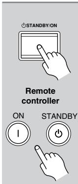
Press the [STANDBY/ON] button. Alternatively, press the remote controller's [AMP] button followed by the [ON] button.
The HT-R520 comes on, the display lights up, and the STANDBY indicator goes off.
To turn off the HT-R520, press the [STANDBY/ON] button. The HT-R520 will enter Standby mode.
Changing the TAPE/MD/CDR Display
If you connect an RI-compatible Onkyo MiniDisc recorder or CD recorder to the TAPE IN/OUT sockets, for RI to work properly, you must change this setting. This setting can only be changed on the HT-R520.
1
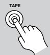
Press the [TAPE] input selector button so that "TAPE" appears on the display.
TYPE
2
Press and hold down the [TAPE] input selector button (about 3 seconds) to set the display.
Repeat this step to select TAPE, MD, or CDR.
Assigning the Digital Inputs to Input Sources
To enjoy Dolby Digital and DTS, you must connect your DVD player to the HT-R520 by using a digital audio connection (coaxial or optical).
With this function you can assign digital audio inputs to input sources. You only need to change these assignments if your connections don't match the default assignments listed below.
| Input source | DIGITAL INPUT |
| DVD | COAX (COAXIAL) |
| VIDEO 1 | ----(Analog) |
| VIDEO 2 | OPT2 (OPTICAL 2) |
| VIDEO 3 | ----(Analog) |
| TAPE | OPT3 (OPTICAL 3) |
| CD | OPT1 (OPTICAL 1) |
For example, if you connect your DVD player to the OPTICAL 1 DIGITAL IN, you'll need to change the DVD input source from COAX to OPT 1, and change the CD input source to something other than OPT 1. If you want to use the TAPE input source with only the analog TAPE IN sockets, you'll need to change the TAPE assignment from "OPT3" to "----" (Analog). You can change the assignments as follows.
1 DVD VIDEO 1 Press the input selector button for the source that you want to assign.
(Digital inputs cannot be assigned to the TUNER input source.)
(TAPE) (Digital inputs cannot be assigned to the TUNER input source.)
2
Press the [DIGITAL INPUT] button.
The current assignment appears.
DUD
COWM
3
Press the [DIGITAL INPUT] button repeatedly to select COAX, OPT1, OPT2, OPT3, or -- --.
DVD
OPT1
Playing Your AV Components
This chapter explains how to use the HT-R520 with your other AV components.
Selecting the Source Component
1 Press the [AMP] button followed by an input selector button to select the component that you want to play.
The name of the selected source appears on the display, as shown.
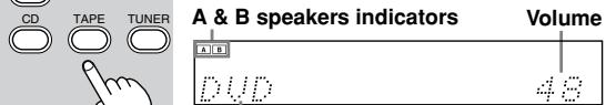
Selected input source
2 Use the [SP A] and [SP B] buttons to select the speaker set that you want to use.
The A and B speaker indicators show whether each speaker set is on or off.
Note: When you turn on speaker set B, the listening mode for speaker set A is set to Stereo automatically.
3 Start playback on the selected component.
4 To adjust the volume, use the MASTER VOLUME control or the remote controller's VOL button.
The volume can be set to MIN, 1 though 79, or MAX.
5 Enjoy listening modes.
See page 38.
Playing Your AV Components—Continued
Displaying Source Information
You can display various information about the current input source as follows.
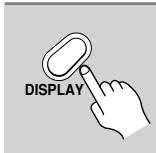
Press the [DISPLAY] button repeatedly to cycle through the available information.
The following information can typically be displayed for input sources.
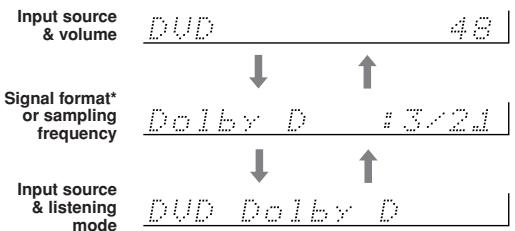
*If the input signal is analog, no format information is displayed. If the input signal is PCM, the sampling frequency is displayed. If the input signal is digital but not PCM, the signal format is displayed. Information is displayed for about three seconds, then the previously displayed information reappears.
Interpreting Surround Channel Information
$$ \begin{array}{c c c} \hline \hline \hline \hline \hline \hline \hline \hline \hline \hline \hline \hline \hline \hline \hline \hline \hline \hline \hline \hline \hline \hline \hline \hline \hline \hline \hline \hline \hline \hline \hline \hline \hline \hline \ \hline A & B & C \ \hline \end{array} $$
A: The number of front channels (front left, front right, and center).
B: The number of surround channels (surround left and surround right). If there's a surround back channel information, this number will be 3.
C: LFE channel for subwoofer (1 means yes).
Using the Multichannel Input
The multichannel input is for connecting a component with individual 5.1-channel analog audio outputs, such as a DVD player or MPEG decoder.
See "DVD Multichannel Connection" on page 24 for connection information.
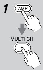
Press the [AMP] button followed by the [MULTI CH] button so that "MULTI" appears on the display.
Audio from the multichannel input will now be used for the DVD input source.
MILL
To adjust the level of individual speakers, use the remote controller's [CH SEL] button to select them, and then use the [LEVEL-] and [LEVEL+] buttons.
The level can be adjusted from -12 to +12dB in 1 dB steps (-15 to +12dB for the subwoofer).
Note that the individual speaker level settings for the multichannel input are independent of those explained on page 47.
Notes:
- While the multichannel input is selected, you can select only the Direct listening mode. If you select the multichannel input while using another listening mode, that listening mode is cancelled.
- While the multichannel input is selected, the Speaker Configuration settings on page 48 are ignored, and signals from the multichannel input are fed to the front left, front right, center, surround left, and surround right speakers and subwoofer regardless of those settings.
Using the Tuner
With the built-in tuner you can enjoy AM and FM radio stations. You can store your favorite stations as presets for quick selection.
Listening to the Radio
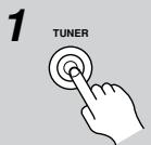
Use the [TUNER] input selector button to select either AM or FM. In this example, FM has been selected.
Tuning into Radio Stations
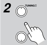
Auto Tuning Mode
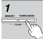
Press the [TUNING MODE] button so that the AUTO indicator appears on the display.
Press the TUNING Up or Down [▲]/[▼] button.
Searching stops when a station is found.
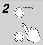
When tuned into an FM station, the TUNED and FM STEREO indicators appear on the display, as shown. When tuned into an AM station, the TUNED indicator appears.
Manual Tuning Mode
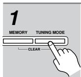
Press the [TUNING MODE] button so that the AUTO indicator disappears from the display.
Press and hold the TUNING Up or Down [] / [] button.
The frequency stops changing when you release the button. Press the buttons repeatedly to change the frequency one step at a time.
HT-R520 changes FM frequency in 0.1 MHz steps, 10kHz steps for AM.
In Manual Tuning mode, FM stations will be in mono. Switch back to Auto Tuning mode for stereo.
Tuning into weak FM stations
If the signal from a stereo FM station is weak, it may be impossible to get good reception. In this case, switch to Manual Tuning mode and listen to the station in mono.
Using the Tuner—Continued
| Presetting Radio Stations | |
| You can store up to 30 of your favorite radio stations as presets. | |
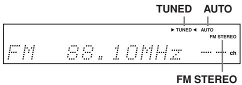
| 1 | Tune into the station that you want to store as a preset. |
| 2 MEMORY TUNING MODE | Press the [MEMORY] button. The MEMORY indicator appears and the preset number flashes. |
| 3 MEMORY PRESET* | While the MEMORY indicator is displayed (about 8 seconds), use the PRESET [▲]/[►] buttons to select a preset from 1 through 30. In this example, preset #3 is selected. |
| 4 MEMORY TUNING MODE | Press the [MEMORY] button again to store the station. The station is stored and the preset number stops flashing. Repeat this procedure for all of your favorite radio stations. |
| Selecting Preset Stations | |
| 1 TUNER | Use the [TUNER] input selector button to select either AM or FM. |
| 2 PRESET | Use the PRESET [/][▶] but-tons, or the remote controller's CH [+/-] button to select the pre-sets. |
| Deleting Presets | |
| 1 | Select the preset that you want to delete. See the previous section. |
| 2 MEMORY TUNING MODE | While holding down the [MEM-ORY] button, press the [TUNING MODE] button. The selected preset is deleted and its number disappears from the display. |
| Displaying Radio Information | |
| 1 DISPLAY | Press the [DISPLAY] button repeatedly to cycle through the available information. |
| When the input source is AM or FM: | |
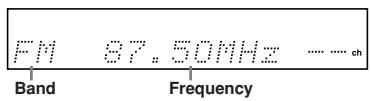
| Band, frequency & preset # | FM 58.10MHz 1 |
| Band & listening mode | FM Stereo |
Common Functions
This chapter explains functions that can be used with any input source.
Before performing any of the procedures in this chapter, press the [AMP] button first to select AMP mode.
Using the OptiResponse Equalizer
When using the HT-R520 with the speakers included in the HTP-520 Home Theater Speaker Package, by turning on the OptiResponse equalizer, you can enjoy a powerful sound with movies or music.

Press the [OR-EQ] button to turn the OptiResponse equalizer on or off.
Setting the Display Brightness
With this function you can adjust the brightness of the display.
Press the [DIMMER] button repeatedly to select: dim, dimmer, or normal brightness.
Adjusting the Bass & Treble
You can adjust the bass and treble for the FRONT SPEAKERS A at any time, except when the Direct listening mode is selected.
If you've selected the multichannel DVD input, before pressing the [TONE] button, press the remote controller's [AMP] button followed by the [SURR] button so that "Tone On" appears on the display.
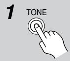
Press the [TONE] button repeatedly to select either Bass or Treble.
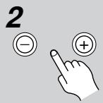
Use the TONE ([-])/([+] buttons to adjust.
Bass
You can boost or cut low-frequency sounds output by the front speakers from -12dB to +12dB in 2 dB steps.
Treble
You can boost or cut high-frequency sounds output by the front speakers from -12dB to +12dB in 2 dB steps.
Note:
- To bypass the bass and treble tone circuits, press the [DIRECT] button to select the Direct listening mode.
Common Functions—Continued
Muting the HT-R520
With this function you can temporarily mute the output of the HT-R520.

Press the remote controller's [MUTING] button.
The output is muted and the MUTING indicator flashes on the display, as shown.
![ONKYO HT-S770 - Press the remote controller's [MUTING] button. - 1](/content/2025/01/151744/images/7963d38ff41785e4ba8ae11ed2b83522936119c83ed958ed7a9c09ca527b8e79.jpg)
To unmute the HT-R520, press the remote controller's [MUTING] button again, or adjust the volume. The output is unmuted and the MUTING indicator goes off. Muting is cancelled when the HT-R520 is set to Standby.
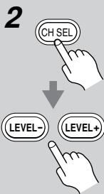
Adjusting Speaker Levels Temporarily
You can adjust individual speaker levels while listening to an input source. These temporary adjustments are cancelled when the HT-R520 is set to Standby.
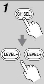
Use the remote controller's [CH SEL] button to select each speaker, and use the [LEVEL-] and [LEVEL+] buttons to adjust the volume.
Speakers are selected in the following order: Left Center Right Surr Right Surr Back Surr Left Subwoofer.
You can adjust the volume of each speaker from -12dB to +12dB (-15dB to +12dB for the subwoofer). The name of the currently selected speaker and its volume appear on the display, as shown.
![ONKYO HT-S770 - Use the remote controller's [CH SEL] button to select each speaker, and use the [LEVEL-] and [LEVEL+] buttons to adjust the volume. - 1](/content/2025/01/151744/images/0f6e790a374881a25885096b4a19336c16f726bd167f607472c83cb1d941fccd.jpg)
Notes:
- You cannot use this function while the HT-R520 is muted.
- Speakers that are set to No or None in the Speaker Configuration cannot be adjusted.
Using the Sleep Timer
With the sleep timer you can set the HT-R520 so that it automatically turns off after a set period.

Press the [SLEEP] button repeatedly to select the required sleep time.
You can set the sleep time from 90 to 10 minutes in 10 minute steps.
The SLEEP indicator appears on the display when the sleep timer has been set, as shown. The specified sleep time appears on the display for about five seconds, then the previous display reappears.
SLEEP indicator
Sleep 90 min
To cancel the sleep timer, press the [SLEEP] button repeatedly until the SLEEP indicator disappears.
To check the remaining sleep time, press the [SLEEP] button. Note that if you press the [SLEEP] button while the sleep time is being displayed, you'll shorten the sleep time by 10 minutes.
Using Headphones
You can connect a pair of stereo headphones (1/4-inch phone plug) to the HT-R520's PHONES jack for private listening, as shown.
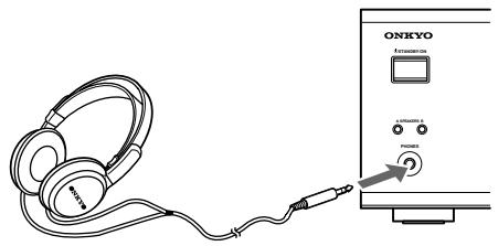
Notes:
- Always turn down the volume before connecting your headphones.
- Speaker sets A and B are turned off while the headphones plug is inserted in the PHONES jack.
- When you connect a pair of headphones, the listening mode is set to Stereo, unless it's already set to Stereo or Direct. When you disconnect the headphones, the previous listening mode is selected.
- When the multichannel DVD input is selected, only the front left and front right sounds can be heard in the headphones.
Using the Listening Modes
With its built-in surround-sound decoders and DSP programs, the HT-R520 can transform your home listening room into a movie theater or concert hall.
To get the most from surround sound, it's important that you install and configure your speakers correctly. See
"Connecting Your Speakers" on page 17 and "Speaker
Configuration" on page 48.
Listening mode availability depends on the format of the current input signal. For example, the Dolby Digital listening modes are available only while a Dolby Digital format signal is being input.
The following table lists all the possible listening modes and indicates which modes can be selected for each input signal format.
| Input Signal Format | PCM, analog | PCM | Dolby Digital | DTS | ||||||
| 96 kHz | 3/2.1 or 3/3.1 | 2/0 (stereo) | Other | 3/2.1 | 2/0 (stereo) | 96/24 *5 | DTS-ES | |||
| Source Listening mode | CD, TV, LD, VHS, MD, vinyl, radio, cassette, cable, satellite, etc. | 96 kHz/24 bit DVD, etc. | DVD, digital cable/satellite, etc. | DVD, LD, CD, etc. | ||||||
| Direct | ○ | ○ | ||||||||
| Stereo | ○ | ○ | ○ | ○ | ○ | ○ | ○ | ○ | ○ | |
| PLII Movie/Music/Game *1 | ○ | ○ | ○ | |||||||
| PLIIx Movie/Game *2 | ○ | ○ | ○ | |||||||
| PLIIx Music *2 | ○ | ○ *3 | ○ | ○ *3 | ○ | ○ *3 | ||||
| Neo:6 Cinema/Music | ○ | |||||||||
| Dolby Digital | ○ | ○ | ||||||||
| Dolby Digital EX *4 | ○ | |||||||||
| DTS | ○ | ○ | ||||||||
| DTS 96/24 | ○ | |||||||||
| DTS-ES Discrete *4 | Discrete | |||||||||
| DTS-ES Matrix *4 | Matrix | |||||||||
| DTS+Neo:6 *3 | ○ | ○ | ||||||||
| DTS+Dolby EX *3 | ○ | ○ | ||||||||
| Onkyo original DSP | Orchestra | ○ | ||||||||
| Unplugged | ○ | |||||||||
| Studio-Mix | ○ | |||||||||
| TV Logic | ○ | |||||||||
| All Ch Stereo | ○ | |||||||||
1: Available when the Surr Back setting in the Speaker Configuration is set to None (see page 48).
2: Available when the Surr Back setting in the Speaker Configuration is NOT set to None (see page 48).
3: Available when the Surr Back setting in the Speaker Configuration is NOT set to None (page 48) and the Dolby Digital/DTS setting (page 42) is set to On.
4: Available when the Surr Back setting in the Speaker Configuration is NOT set to None (page 48) and the Dolby Digital/DTS setting (page 42) is set to either On or Auto.
*5: For DTS 96 kHz/24-bit material, if the listening mode is Stereo or DTS 96/24, audio is processed at 96 kHz. For all other listening modes, it's processed at 48 kHz.
Tip: You can check the format of a digital input signal on page 33, "Displaying Source Information."
Using the Listening Modes—Continued
Selecting Listening Modes
See "About the Listening Modes" on page 40 for detailed information about the listening modes.
- The Dolby Digital and DTS listening modes can only be selected if your DVD player is connected to the HT-R520 with a digital audio connection (coaxial or optical).
- Listening mode availability depends on the format of the current input signal.
- While speaker set B is on or a pair of headphones are connected, you can only select the Direct or Stereo listening mode.
- While the multichannel input is being used, only the Direct listening modes can be selected.
Selecting on the HT-R520
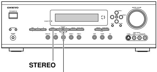
LISTENING MODE
[STEREO] button
This button selects the Stereo listening mode.
LISTENING MODE [←] [▶] buttons
These buttons select all of the listening modes that can be used with the current input source. The surround modes available also depends on the Dolby Digital/DTS setting (see page 42).
Selecting with the Remote Controller
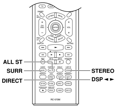
[DIRECT] button
This button selects the Direct listening mode.
[STEREO] button
This button selects the Stereo listening mode.
[SURR] button
This button selects the Dolby Digital and DTS listening modes. The modes available depends on the Dolby Digital/DTS setting.
When the multichannel DVD input is selected, this button is also used when adjusting the bass and treble (see page 36).
[DSP] & [DSP▶] buttons
These buttons select the Onkyo original DSP modes.
[All ST] button
This button selects the All Ch Stereo listening mode.
Using the Listening Modes—Continued
About the Listing Modes
The HT-R520's surround indicators show which speakers are active in each listening mode.
Front left

Center

Front right

Subwoofer

Surround left

Surround back

Surround right
Basic Modes
Direct

The selected input source is output by the front left and right speakers only, with minimal processing for a pure sound.
Stereo

The selected input source is processed as a stereo signal and output by the front left and right speakers and the subwoofer.
Surround Modes
Dolby Pro Logic II

Dolby Pro Logic II creates 5.1-channel surround from two-channel material.
- Dolby Pro Logic II Movie
Use this mode with DVDs and videos that bear the Dolby Sur
DO BY SURROUND
round logo or TV programs that feature Dolby Surround. You can also use this mode with stereo movies or TV programs.
- Dolby Pro Logic II Music
Use this mode with the stereo sources such as music CDs and DVDs.
- Dolby Pro Logic II Game
Use this mode with video games that feature stereo sound.
Dolby Pro Logic IIx

Dolby Pro Logic IIx can create 6.1-channel surround from two-channel material (except 96kHz PCM). The Dolby Pro Logic IIx Music mode can create 6.1-channel surround from 5.1-channel audio material.
- Dolby Pro Logic IIx Movie
Use this mode with DVDs and videos that bear the
DOLBY SURROUND or TV programs that feature Dolby Surround. You can also use this mode with stereo movies, TV programs, or other 2-channel sources.
- Dolby Pro Logic IIx Music
Use this mode with CDs and DVDs that bear the
DOLBY SURROUND or DOLBY. It can also be used with other 5.1-channel sources to create 6.1-channel surround.
- Dolby Pro Logic IIx Game
Use this mode with video games that feature stereo sound.
Neo:6

This mode creates 6.1-channel surround from 2-channel analog sources. It offers six full-bandwidth channels with excellent separation. There are two modes of operation: Cinema mode, which is suited to movies, and Music mode, which is for listening to music.
- Cinema mode simulates the realistic sense of movement that you get with 6.1-channel surround sound sources. Use this mode with videos, DVDs, and TV programs that feature stereo sound.
- Music mode uses the surround channels to simulate a natural sound field that cannot be produced with conventional stereo. Use this mode with stereo source material such as music CDs.
Dolby Digital

With this format you can experience the same superb sound that you get at a movie

DIGITAL
theater or concert hall. Use this mode with DVDs that bear the Dolby Digital logo.
Dolby Digital EX

With an added surround-back channel, this 6.1 channel format offers a heightened sense of space, for added realism with

DIGITAL
moving sounds, such as those that rotate 360 degrees or pass overhead. Dolby Digital EX material can also be played on conventional 5.1 channel systems, in which case the surround-back channel audio is divided between the surround left and right channels. Use this mode with DVDs that have a 6.1-channel soundtrack and bear the Dolby Digital logo.
DTS

This digital surround format offers a surround sound experience with exceptional fidelity. It uses compressed digital audio data, with six discrete channels (5.1), and 1

SURROUND
the ability to handle large amounts of audio data while remaining faithful to the original. DTS provides very high-quality sound. You'll need a DTS compatible DVD player in order to enjoy DTS material. Use this mode with DVDs, LDs, or CDs that bear the DTS logo.
DTS 96/24

This mode provides better audio quality. Use it with CDs, DVDs, and LDs that bear the
Using the Listening Modes—Continued
DTS-ES

DTS-ES supports up to 6.1 channels. The HT-R520 supports both DTS-ES Discrete and DTS-ES Matrix.
Discrete mode is for use with DTS 6.1
material. With an additional surround-back

channel, each 6.1 channel is digitally recorded for a realistic sense of movement and space. Use it with CDs, DVDs, and LDs that bear the DTS-ES logo.
Matrix mode creates 6.1-channel surround from DTS 5.1 material. Since DTS 5.1
includes surround-back channel information, the channel can be reconstructed for playback on 6.1-channel systems. Use this
mode with CDs, DVDs, and LDs that bear the DTS-ES or DTS logo.
DTS+Neo:6

This mode uses the Neo:6 decoder to create 6.1-channel surround from DTS 5.1-channel material. Use it with CDs, DVDs, and LDs that bear the DTS or DTS 96/24 logo.
DTS+Dolby EX
This mode uses the Dolby EX decoder to create 6.1-channel surround from DTS 5.1-channel material. Use it with CDs, DVDs, and LDs that bear the DTS or DTS 96/24 logo.
Onkyo Original DSP Modes
Orchestra

Suitable for classical or operatic music. The center speaker is turned off and the surround channels are emphasized in order to widen the stereo image. In addition, it simulates the natural reverberation of a large hall.
Unplugged
Suitable for acoustic instrument sounds, vocals, and jazz music. By emphasizing the front stereo image, it simulates the stage-front experience.
Studio-Mix
Suitable for rock and pop music. Listening to music in this mode creates a lively sound field with a powerful acoustic image, like being at a club or rock concert.
TV Logic

Adds realistic acoustics to TV programs produced in a TV studio. In addition, it adds surround effects to the entire sound and clarity to voices.
All Ch Ste

Ideal for background music. The front, surround, and surround back channels create a stereo image that fills the entire listening area.
Listening mode indicators
| Listening mode | Display |
| Direct | DIRECT |
| Stereo | STEREO |
| PL II Movie/Music/Game | ☐ PL Ⅱ |
| PL IIx Movie/Music/Game | ☐ PL Ⅱx |
| Neo:6 Cinema/Music | ☐s Neo:6 |
| Dolby Digital | ☐ D |
| Dolby Digital EX | ☐ D EX |
| DTS | ☐s |
| DTS 96/24 | ☐s 96/24 |
| DTS-ES | ☐s ES |
| DTS+Neo:6 | ☐s Neo:6 |
| DTS+Dolby EX | ☐ EX ☐s |
| Onkyo Original DSP | DSP |
Using the Listening Modes—Continued
Dolby Digital/DTS setting (5.1 or 6.1-channel playback)
If the Surr Back setting is set to anything other than None in the Speaker Configuration (page 48), and if the surround information in the current input signal is "3/2.1" or "3/3.1" (you can check the format of a digital input signal on page 33, "Displaying Source Information"), you can determine whether Dolby Digital and DTS material is played using 6.1-channels or 5.1-channels.
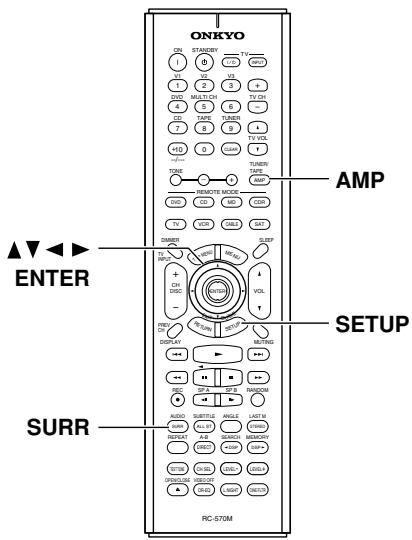
1
Press the [AMP] mode button followed by the [SETUP] button.

2
Use the Up and Down [ ] / [ ] buttons to select "4. Audio Adjust," and then press the [ENTER] button.
- Audio Modulus
3

When playing Dolby Digital material:
Use the Up and Down [] / [] buttons to select "SB (Dolby D)," and then use the Left and Right [] / [] buttons to select "Auto," "On," or "Off."
When playing DTS material: Use the Up and Down [ ] / [ ] buttons to select "SB (DTS),"and then use the Left and Right [ ]/ [ ] buttons to select "Auto," "On" or "Off."

4
Press the [SETUP] button. Setup closes.
5
Use the remote controller's [SURR] button, or the HT-R520's LISTENING MODE []/[] buttons to select the required listening mode.
Dolby Digital Setting
Auto: If the source signal contains a Dolby Digital EX flag, Dolby Digital EX 6.1 is used. If not, Dolby Digital 5.1 is used.
On: Dolby Digital EX 6.1 is used regardless of whether the source signal contains a Dolby Digital EX flag. You can switch between Dolby Digital EX and PL IIx Music.
Off: Dolby Digital 5.1 is used even if a Dolby Digital EX flag is present.
DTS Setting
Auto: If the source signal contains a DTS-ES flag, DTS-ES Discrete (6.1) or DTS-ES Matrix (6.1) is selected automatically. If not, DTS 5.1 is used.
On: DTS-ES 6.1 is used regardless of whether the source signal contains a DTS-ES flag. If the source signal contains a DTS-ES flag, DTS-ES Discrete (6.1) or DTS-ES Matrix (6.1) is selected automatically. If the source signal does not contain a DTS-ES flag, you can select DTS+Dolby EX, PL IIx Music, or DTS+Neo:6.
Off: DTS 5.1 is used for all DTS sources, even if a DTS-ES flag is present.
Recording
This chapter explains how to record the selected input source to an AV component with recording capability, and how to record audio and video from two different sources.
Recording the Input Source
You can record only to AV components that are connected to the TAPE OUT or VIDEO 1 OUT sockets. See pages 22-30 for information on connecting your AV components to the HT-R520.
| 1 DVD VIDEO 1 VCR VIDEO 2 VIDEO 3 TAPE Remote controller V1 V2 V3 DVD CD TAPE TUNER | Use the input selector buttons to select the AV component that you want to record. Audio signals from the selected input source are output by the VIDEO 1 OUT and TAPE OUT sockets. You can listen to the source while recording. The HT-R520's VOLUME control has no effect on recording. |
| 2 | Start recording on the AV component connected to the TAPE OUT or VIDEO 1 OUT sockets. |
| 3 | Start playback on the source AV component. |
Notes:
- You cannot record from AV components that are connected to the digital inputs. You must use analog connections.
- The surround effects produced by the surround and DSP listening modes cannot be recorded.
- You cannot record from an AV component that is connected to the multichannel input.
- If you select another input source while recording, that input source will be recorded instead.
Recording from Different AV Sources
With this function you can record audio and video from different sources, allowing you to overdub audio onto your video recordings. This function takes advantage of the fact that when an audio-only input source (i.e., TAPE, TUNER, or CD) is selected, the video input source remains unchanged. For example, if you first select the VIDEO 3 input source, followed by the CD input source, you can watch the video from the VIDEO 3 input and listen to the audio from the CD input.
In the following example, audio from the CD player connected to the CD IN sockets, and video from the cam-corder connected to the VIDEO 3 INPUT VIDEO socket are recorded by the VCR, which is connected to the VIDEO 1 OUT sockets.
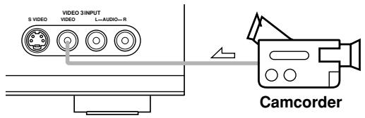
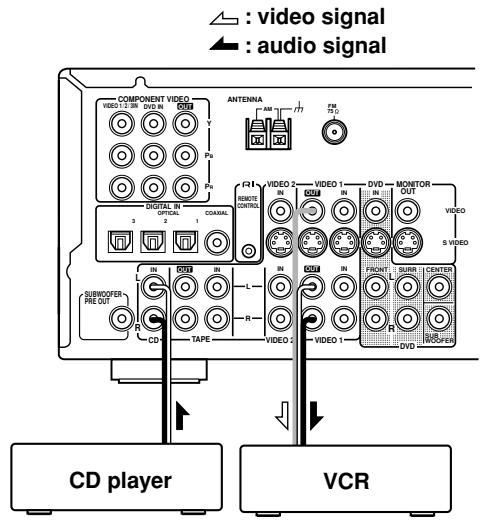
- Prepare the camcorder and CD player for playback.
- Prepare the VCR for recording.
- Press the [VIDEO 3] input selector button.
- Press the [CD] input selector button. This selects the CD player as the audio source, but leaves the camcorder as the video source.
- Start recording on the VCR and start playback on the camcorder and CD player.
The video from the camcorder and the audio from the CD player are recorded by the VCR.
Advanced Function
Using the Audio Adjust Functions
These functions only work with speaker set A. Audio Adjust provides various functions for adjusting the sound.
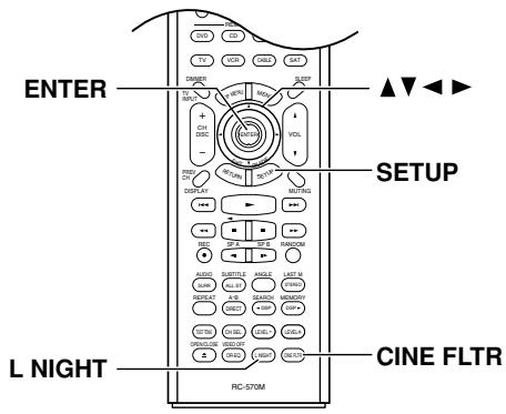

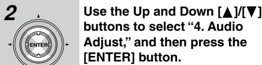
- n 且 i I, j J 且 i J 时


The Audio Adjust functions are explained below.
Double Bass
The Double Bass function boosts the bass by feeding bass sounds from the front left and right channels to the subwoofer. To use this function, in the Speaker Configuration, the Subwoofer setting must be set to Yes and the Front setting must be set to Large (see page 48).
The Double Bass function works well with mono and 2-channel sources, including 96kHz PCM.
On: Double Bass function on.
Off: Double Bass function off.
Late Night (Dolby Digital only)
With this function you can reduce the dynamic range of Dolby Digital material so that you can still hear quiet parts even when listening at low volume levels—ideal for watching movies late at night when you don't want to disturb anyone.
Off: Late Night function off.
Low: Small reduction in dynamic range.
High: Big reduction in dynamic range.
Note that the effect of the Late Night function depends on the Dolby Digital material that you are playing, and with some material there will be little or no effect.
This function is turned off when the HT-R520 is set to Standby.
Tip: You can also set this function by using the remote controller's [L NIGHT] button.
CinemaFILTER
With this function, you can soften the harshness, or brightness sometimes experienced with movie soundtracks, which are typically mixed for reproduction in a movie theater.
You can set the CinemaFILTER function to On or Off. The CinemaFILTER function can be used with the following listening modes: Dolby Digital, Dolby Digital EX, Dolby Pro Logic II Movie, Dolby Pro Logic IIx Movie, DTS, DTS-ES, DTS Neo:6 Cinema, DTS 96/24, DTS+Neo:6, and DTS+Dolby EX.
Tip: You can also set this function by using the remote controller's [CINE FLTR] button.
Adjusting the DTS Neo:6 Music Mode
Center Image
DTS Neo:6 derives a center-channel signal from stereo material, either analog or digital. In Music mode, the center speaker is intended to augment the left and right speakers, allowing them to faithfully reproduce the original stereo mix. For this reason, the center channel sound is not fully subtracted from the left and right channels. With this function, you can adjust the amount of subtraction depending on your room layout and personal preference.
Advanced Function—Continued
0 to 5: Adjustable range.
When set to 5, nothing is subtracted from the left and right channels. When set to 0, the left and right channel levels are halved (-6dB) , making the center channel more dominant, particularly useful when the listener is off-center.
This function has no effect on the level of the center speaker.
Adjusting the PL II or PL IIx Music Mode
The following Panorama, Dimension, and Center Width parameters can only be adjusted while the PL II Music or PL IIx Music listening mode is selected.
These parameters cannot be adjusted if you're using the Pro Logic IIx listening mode for 6.1-channel playback from a 5.1-channel source.
Panorama
With this function, you can extend the front stereo image to the surround speakers to provide a "wraparound" effect, especially useful when not much sound is being output by the surround speakers.
Dimension
With this function, you can move the soundfield backward or forward.
0 to 6: Adjustable range.
When set to 3, the soundfield is in the normal position. Choose a lower setting to move the soundfield forward Choose a higher setting to move it backward.
If the stereo image is too wide, or there's too much surround information, try moving the soundfield forward to achieve a better balance. If the stereo image is too narrow, or it sounds almost like it's in mono, try moving the soundfield backward.
Center Width
With Pro Logic II/Pro Logic IIx decoding, the center-channel signal is normally output by the center speaker. If a center speaker is not used, the decoder divides the center signal equally between the front left and right speakers, producing what's known as a "phantom" center. With this function you can choose to have the center-channel signal output by the center speaker only, by the front left and right speakers only ("phantom" center), or by a mix of the two.
0 to 7: Adjustable range.
When set to 0, the center-channel signal is output by the center speaker only. When set to 7, it's output by the front left and right speakers only ("phantom" center).
In home theaters, adding some width to the center channel can improve the balance between the center and front left and right speakers. Most stereo material will benefit from appropriate use of this function.
Digital Input Signal Formats
The following table shows the display indicators for each supported digital signal format.
| Format | Display |
| Dolby Digital | D D |
| DTS | D T S |
| PCM | PCM |
Normally, the HT-R520 detects the signal format automatically. However, if you experience either of the following issues when playing PCM or DTS material, you can set the signal format to PCM or DTS:
- If the beginnings of tracks from a PCM source are cut off, try setting the format to PCM.
- If noise is produced when fast forwarding or reversing a DTS CD or LD, try setting the format to DTS.
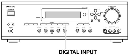
1 Press and hold the HT-R520's [DIGITAL INPUT] button on the front panel for about 3 seconds.
2 While "Auto" is displayed (about 3 seconds), use the Left and Right [▲] [/▶] buttons to select: PCM, DTS, or Auto.
DTS or PCM; the DTS or PCM indicator, depending on which format you have set, flashes, and only signals in that format are output. Digital signals in other formats are ignored.
Auto (default); the format is detected automatically. If no digital input signal is present, the corresponding analog input is used instead.
Advanced Setup
Advanced setup cannot be set while headphones are connected, Speaker B is on, or the multi channel input is being used.
Speaker Distance
To get the best from surround sound, it's important that the sound from each speaker reaches the listener at the same time. To achieve this, you need to specify the distance from each speaker to the listening position.
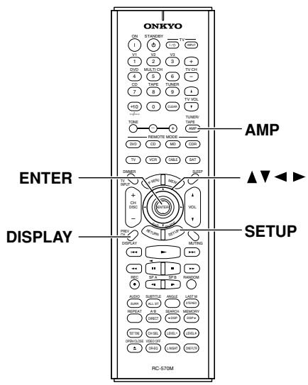
1
Measure and make a note of the distance from each speaker to the listening position.
2
Press the [AMP] button followed by the [SETUP] button on the remote controller.
3
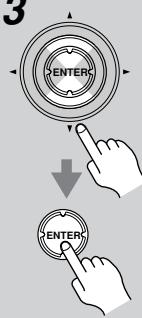
Use the Up and Down [ ] / [ ] buttons to select "2. SP Distance," and then press the [ENTER] button.
2.5P Distance
4

Use the [DISPLAY] button to switch ft or m.
ft: distances in feet. Can be set from 1 to 30 feet in 1-foot steps.
m: distances in meters. Can be set from 0.3 to 9 meters in 0.3-meter steps.
5
Use the Left and Right [] / [] buttons to specify the distance for "Front," then press the Down [▼] button to select the next speaker.
6
Repeat step 5 for all speakers.
Note:
Speakers that you set to No or None in the Speaker Configuration (page 48) cannot be selected.
7

Press the [SETUP] button.
Setup closes.
Notes:
- The Center and Subwoofer distances can be set up to 5 ft. (1.5 m) more or less than the Front distance. For example, if the Front distance is set to 20 ft. (6 m), the Center and Subwoofer distances can be set between 15 and 25 ft. (4.5 and 7.5 m).
- The SurrRight, Surr Left, and Surr Back distances can be set up to 5 ft. (1.5 m) more or 15 ft. (4.5 m) less than the Front distance. For example, if the Front distance is set to 20 ft. (6 m), the SurrRight, Surr Left, and Surr Back distances can be set between 5 and 25 ft. (1.5 and 7.5 m).
Advanced Setup—Continued
Speaker Levels
With this function you can adjust the volume of each speaker so that all speakers can be heard equally at the listening position.
Speaker levels cannot be set while the HT-R520 is muted.
1
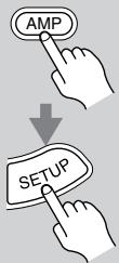
Press the [AMP] button followed by the [SETUP] button on the remote controller.
2
Use the Up and Down [▲]/[▼] buttons to select "3. Level Cal," and then press the [ENTER] button.
A pink noise test tone is output by the front left speaker.
3.Level Cal
3
Turn up the volume so that you can hear the test tone sufficiently.
While each speaker outputs the test tone, its name appears on the display, as shown.
L中生 0dE
4
Use the Left and Right []/[] buttons to adjust the speaker level, and use the Down [] button to select the next speaker.
The level can be adjusted from -12 to +12dB in 1 dB steps (-15 to +12dB for the subwoofer).
5
Repeat step 4 so that the level of the test tone from each speaker is the same.
Speakers that you set to No or None in the Speaker Configuration (page 48) do not output the test tone.
6

Press the [SETUP] button.
Setup closes.
Don't forget to turn down the volume if you turned it up while setting the levels.
Notes:
- This procedure can also be performed by using the remote controller. First press the [TEST TONE] button to output the test tone. Use the [LEVEL-] and [LEVEL+] buttons to adjust the levels, and use the [CH SEL] button to select the speakers.
Advanced Setup—Continued
These settings only need to be changed if you're not using the HTP-520 speakers. If you are using the all HTP-520 speakers, you don't need to change anything.
Speaker Configuration
This section explains how to specify which speakers are connected and their sizes.
For speakers with a cone diameter larger than 6-1/2 inches (16 cm), specify Large. For those with a smaller diameter, specify Small.
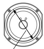
Cone diameter
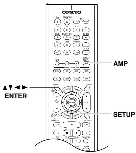
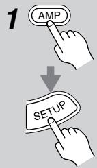
Press the [AMP] button followed by the [SETUP] button.
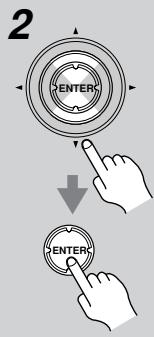
Use the Up and Down [] / [] buttons to select "1. SP Config," and then press the [ENTER] button.
1.5PConf i g
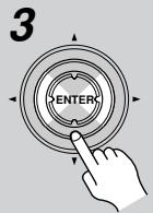
While the Subwoofer setting is selected, use the Left and Right [<] [/>] buttons to select Yes or No.
Yes: Select if a subwoofer is connected.
No: Select if no subwoofer is connected.
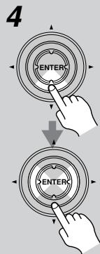
Use the Down [▼] button to select “Front,” and then use the Left and Right [▲]/[▶] buttons to select Small or Large.
Small: Select if the front speakers are small.
Large: Select if the front speakers are large.
Note:
- If the Subwoofer setting in step 3 is set to No, this setting is fixed at Large and does not appear.
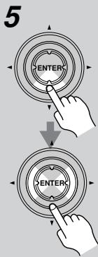
Use the Down[▼] button to select “Center,” and then use the Left and Right [▲]/[▶] buttons to select Small, Large, or None.
Small: Select if the center speaker is small.
Large: Select if the center speaker is large.
None: Select if no center speaker is connected.
Note:
- If the Front setting in step 4 is set to Small, the Large option cannot be selected.
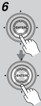
Use the Down[▼] button to select "Surround," and then use the Left and Right [▲]/[▶] buttons to select Small, Large, or None.
Small: Select if the surround left and right speakers are small.
Large: Select if the surround left and right speakers are large.
None: Select if no surround left and right speakers are connected.
Note:
- If the Front setting in step 4 is set to Small, the Large option cannot be selected.
Advanced Setup—Continued
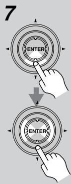
Use the Down [▼] button to select "Surr Back," and use the Left and Right [▲]/[▶] buttons to select Small, Large, or None.
Small: Select if the surround back speaker is small.
Large: Select if the surround back speaker is large.
None: Select if no surround back speaker is connected.
Notes:
- If the Surround setting in step 6 is set to None, this setting does not appear.
- If the Surround setting in step 6 is set to Small, the Large option cannot be selected.
Crossover Frequency
To get the best bass performance from your speaker system, you need to set the crossover frequency according to the size and frequency response of your subwoofer and other speakers (front, center, and surround).
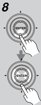
Use the Down [▼] button to select "Crossover," and then use the Left and Right [▲]/[▶] buttons to select a crossover frequency.
Choose a crossover frequency suitable for your setup.
If you're using a subwoofer, choose a crossover frequency based on the diameter of your front speakers.
If you're not using a subwoofer, use the diameter of the first speaker that you specified as Small in steps 4 through 7 in the "Speaker configuration" setting.
| Speaker cone diameter | Crossover frequency |
| Over 8 in. (20 cm) | 60Hz |
| 6-1/2 to 8 in. (16–20 cm) | 80Hz |
| 5-1/4 to 6-1/2 in. (13–16 cm) | 100Hz (default) |
| 3-1/2 to 5-1/4 in. (9–13 cm) | 120Hz |
| Under 3-1/2 in. (9 cm) | 150Hz |

Press the [SETUP] button. Setup closes.
Notes:
- For a more accurate setting, look up the frequency response in the manuals supplied with your speakers and set accordingly. In addition, listen to some music that you know well and choose a higher crossover frequency if you think there's not enough sound coming from the subwoofer; a lower setting if you think there's too much.
To test that all of your speakers are working properly, press the remote controller's [TEST TONE] button. The test tone will be output by each speaker in turn and the name of each speaker will appear on the display. To turn off the test tone, press the [TEST TONE] button again.
- If the test tone is not produced by a speaker, or it's produced by a speaker other than that shown on the display, you may have wired your speakers incorrectly and you should check your connections (see page 17).
- If the test tone is not produced by a speaker and its name does not appear on the display, you may have set the speaker settings incorrectly (see page 48).
Controlling Other Components
You can use the HT-R520's remote controller (RC-570M) to control your other AV components, including those made by other manufacturers. To do this you first need to enter the appropriate remote control code for your DVD player, TV, VCR, cable receiver, or satellite receiver. Then you need to select the corresponding remote controller mode (see page 10).
By entering the appropriate remote control code, the [CD], [MD], and [CDR] mode buttons can also be used with other manufacturer's components (e.g., DVD, TV, VCR, satellite or cable receiver).
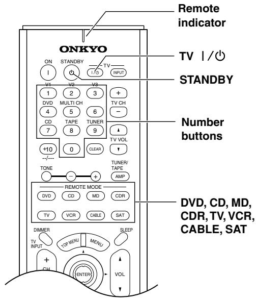
Entering Remote Control Codes
Entering the appropriate remote control code for your TV, VCR, and so on will allow you to control it with the HT-R520's remote controller. You'll need to perform this procedure for each component that you want to control.
1 Look up the remote control code for your component.
See "Remote Control Codes" on page 51.
2 While holding down the [DVD], [TV], [VCR], [CABLE], [SAT], [CD], [MD], or [CDR] mode button, press the [STANDBY] button.
Remote indicator flashes twice.
3 Within 30 seconds, use the number buttons to enter the 4-digit remote control code.
4 Select the remote controller mode, point the remote controller at the component, and check its operation.
Remote controller buttons that can be used in DVD mode are shown on page 12. Those that can be used with the TV, VCR, CABLE, and SAT modes are shown on page 55.
If the remote controller works as expected, the code has been entered correctly. If not, try again or try another code.
Codes for Onkyo DVD Players
The remote control code for an Onkyo DVD player depends on whether it's connected via RI, as follows:
5001: Use this code if you've connected an RI cable and an analog audio cable (RCA) to your DVD player. This is the default setting, so if you're using RI, you don't need to change anything. Point the remote controller at the HT-R520 to operate the DVD player.
5002: Use this code if your DVD player doesn't have an RI socket, or you're not using RI. Point the remote controller at the DVD player to operate it.
Resetting the [DVD], [CD], [MD] or [CDR] Mode Button
By default, the [DVD], [CD], [MD] & [CDR] mode buttons are preprogrammed with remote control codes for controlling Onkyo components connected via R1. If you've entered another code for a button and now want to return to its default, perform the following procedure.
1 While holding down the mode button that you want to reset, press the TV [O/I] button.
Remote indicator flashes twice.
2 Press the mode button again.
The mode button is reset.
Resetting the Remote Controller
This section explains how to reset the remote controller to its default settings.
1 While holding down the [AMP] mode button, press the [STANDBY] button.
Remote indicator flashes 5 times.
2 Press the [AMP] mode button again.
The remote controller is reset.
Controlling Other Components—Continued
Remote Control Codes
When two or more codes are given, try each one in turn, and choose the one that works best.
Depending on the manufacturer and component, the remote controller may not work as expected.
DVD (DVD player)
| Manufacturer | Control code |
| Aiwa | 5010 |
| Akai | 5019 |
| Apex | 5015, 5016 |
| CyberHome | 5027 |
| Denon | 5017, 5020 |
| GE | 5003 |
| Hitachi | 5009 |
| Integra | 5001, 5002 |
| Integra Research | 5001, 5002 |
| JVC | 5023 |
| Kenwood | 5017 |
| Magnavox | 5004, 5021 |
| Marantz | 5025, 5026 |
| Mitsubishi | 5005 |
| Onkyo | 5001, 5002 |
| Panasonic | 5011, 5017, 5020 |
| Philips | 5004, 5021, 5028 |
| Pioneer | 5006 |
| Proscan | 5003 |
| RCA | 5003 |
| Sanyo | 5012 |
| Sony | 5007, 5013, 5018, 5029 |
| Technics | 5020 |
| Thomson | 5022, 5024 |
| Toshiba | 5008, 5021 |
| Xbox | 5022 |
| Yamaha | 5020 |
| Zenith | 5014, 5021 |
SAT (satellite receiver)
| Manufacturer | Control code |
| Alba | 4014, 4017, 4025, 4027 |
| Allsat | 4015, 4027 |
| Alltech | 4022, 4025 |
| Amstrad | 4013, 4019, 4025, 4030, 4031 |
| Anglo | 4025 |
| Ankaro | 4025 |
| Anttron | 4017 |
| Apollo | 4017 |
| Arcon | 4016 |
| Armstrong | 4013 |
| Asat | 4016 |
| Astra | 4013, 4016, 4024 |
| Astro | 4019, 4020 |
| AudioTon | 4015 |
| Bush | 4012, 4014 |
| Condor | 4024 |
SAT (satellite receiver)
| Manufacturer | Control code |
| Conrad | 4024 |
| Cosat | 4015, 4023 |
| Crown | 4013 |
| Daewoo | 4016, 4017, 4025 |
| Diamond | 4022 |
| Dishnet | 4008 |
| Dual | 4016 |
| Echostar | 4010, 4018, 4025 |
| Einhell | 4013, 4017, 4025 |
| Elta | 4015, 4017 |
| Engel | 4025 |
| Eurosat | 4013, 4022 |
| Eurosky | 4013, 4024 |
| Eurostar | 4024 |
| Fagor | 4015, 4023 |
| Ferguson | 4012 |
| Fidelity | 4030 |
| Fracarro | 4017 |
| FTE | 4025, 4030 |
| Fuba | 4017 |
| Galaxis | 4015, 4023 |
| GE | 4001, 4002 |
| General Instruments | 4003 |
| GMI | 4013 |
| Grundig | 4021, 4029, 4031 |
| Hinari | 4017 |
| Hirschmann | 4019, 4035 |
| Hitachi | 4036, 4037 |
| Hughes Network Systems | 4011 |
| Huth | 4013, 4015, 4024 |
| Imperial | 4014 |
| Intertronic | 4013 |
| Intervention | 4015, 4023, 4024 |
| Johansson | 4015 |
| JVC | 4009, 4021 |
| Kathrein | 4025 |
| Kolon | 4017 |
| K-SAT | 4025 |
| Kyostar | 4017 |
| Lasat | 4013, 4020, 4024 |
| Lenco | 4016, 4017, 4025 |
| Lennox | 4023 |
| Loewe | 4013 |
| Lorenzen | 4024 |
| Macab | 4022 |
| Manhattan | 4015, 4020, 4023 |
| Maspro | 4021, 4025 |
| Matsui | 4021 |
| Mediamarkt | 4013 |
| Medion | 4025 |
| Metronic | 4013, 4017, 4020 |
| Micro Technology | 4025 |
| Minerva | 4021 |
| Morgan's | 4013, 4015, 4025 |
| Mysat | 4025 |
| Neuhaus | 4019, 4023, 4024, 4025 |
| Neusat | 4025 |
SAT (satellite receiver)
| Manufacturer | Control code |
| Nikko | 4013, 4025, 4027 |
| Nokia | 4033 |
| Nordmende | 4017, 4020 |
| Oceanic | 4022 |
| Octagon | 4016, 4017 |
| Okano | 4013 |
| Optex | 4015, 4023 |
| Orbit | 4016 |
| Orbitech | 4017, 4019 |
| Pace | 4012, 4026, 4031 |
| Pacific | 4022 |
| Palladium | 4013, 4017, 4021 |
| Palsat | 4019 |
| Panasonic | 4006, 4031 |
| Panda | 4024 |
| Philips | 4021, 4029 |
| Photonrend | 4015, 4023 |
| Predki | 4017 |
| Premier | 4023 |
| Primestar | 4007 |
| Proscan | 4001, 4002 |
| Protek | 4022 |
| Pye | 4021 |
| Quelle | 4024 |
| Radix | 4035 |
| RCA | 4001, 4002 |
| Roadster | 4025 |
| Rover | 4025 |
| Saba | 4014, 4020, 4024, 4027 |
| Samsung | 4017 |
| Satcom | 4024 |
| SatPartner | 4017, 4020, 4027, 4030 |
| Schneider | 4029 |
| Sedea Electronique | 4017 |
| Seemann | 4013 |
| SEG | 4017, 4028 |
| Seleco | 4015, 4023 |
| Skymaster | 4025, 4034 |
| Skyvision | 4015 |
| Sony | 4005, 4031 |
| Strong | 4016, 4017, 4020 |
| Sunstar | 4013 |
| Techniland | 4015, 4023 |
| TechniSat | 4019 |
| Teco | 4013, 4016 |
| Teleciel | 4027 |
| Telefunken | 4017 |
| Teleka | 4013 |
| Telemaster | 4020 |
| Telewire | 4015, 4023 |
| Tensai | 4016 |
| Thomson | 4024, 4025 |
| Thorens | 4022 |
| Tonna | 4015, 4023, 4025 |
| Toshiba | 4004 |
| Triasat | 4019 |
Controlling Other Components—Continued
SAT (satellite receiver)
| Manufacturer | Control code |
| Tristar | 4016 |
| Unisat | 4013 |
| Universum | 4021, 4024 |
| Vortec | 4017 |
| Wela | 4025 |
| Zehnder | 4020 |
| Zenith | 4032 |
CBL (cable receiver)
| Manufacturer | Control code |
| ABC | 3001, 3002, 3021 |
| Archer | 3006 |
| Cabletime | 3028, 3032 |
| Cableview | 3004 |
| Contec | 3009 |
| Eastern | 3010 |
| GE | 3001, 3002 |
| Gemini | 3011 |
| General Instruments | 3002, 3022 |
| Grundig | 3031 |
| Hamlin | 3012 |
| Hitachi | 3002 |
| Jerrold | 3002, 3011, 3013, 3021, 3022, 3023, 3026 |
| Magnavox | 3014 |
| Memorex | 3015 |
| Movie Time | 3016 |
| NEC | 3003 |
| Nokia | 3033 |
| NSC | 3016 |
| Oak | 3009 |
| Panasonic | 3020 |
| Philips | 3007, 3008, 3014 |
| Pioneer | 3017, 3024 |
| Proscan | 3001, 3002 |
| RCA | 3004, 3020, 3022 |
| Realistic | 3006 |
| Sagem | 3034 |
| Salora | 3029 |
| Samsung | 3017 |
| Signature | 3002 |
| Sprucer | 3020 |
| Standard Component | 3018 |
| Starcom | 3011, 3021 |
| Stargate | 3011 |
| Tele+1 | 3030 |
| Tocom | 3013 |
| United Cable | 3021, 3023 |
| Universal | 3005, 3006 |
| Videoway | 3025 |
| View Star | 3009, 3014, 3016 |
| Zenith | 3019 |
VCR
| Manufacturer | Control code |
| Aiwa | 2012, 2046, 2047 |
| Akai | 2003, 2004, 2022 |
| Alba | 2033, 2041, 2044, 2045, 2047 |
| Anitech | 2033 |
| ASA | 2034 |
| Baird | 2036 |
| Bell & Howell | 2007 |
| Blaupunkt | 2039, 2042 |
| Bush | 2033, 2041, 2044, 2045, 2047 |
| Canon | 2010, 2011 |
| Carver | 2014 |
| Cimline | 2033 |
| Citizen | 2008, 2009 |
| Colortyme | 2005 |
| Craig | 2008 |
| Crown | 2033 |
| Curtis Mathes | 2001, 2005, 2008, 2009, 2010, 2011, 2023, 2026 |
| Cyrus | 2034 |
| Daewoo | 2012 |
| Dansai | 2033 |
| Decca | 2034 |
| Dimensia | 2001, 2026 |
| Dumont | 2034, 2036, 2037 |
| Elcatech | 2033 |
| Emerson | 2003, 2010, 2012, 2022 |
| ESC | 2043 |
| Ferguson | 2035 |
| Finlandia | 2034, 2036 |
| Finlux | 2034, 2036, 2037 |
| Firstline | 2033, 2041 |
| Fisher | 2007, 2030, 2036 |
| Fuji | 2004, 2010, 2024 |
| Funai | 2012 |
| Garrard | 2012 |
| GE | 2001, 2002, 2008, 2010, 2011, 2023, 2025, 2026 |
| GEC | 2034 |
| GoldHand | 2033 |
| GoldStar | 2005, 2009 |
| Goodmans | 2031, 2033 |
| Gradiente | 2012 |
| Graetz | 2036, 2043 |
| Granada | 2030, 2034, 2036 |
| Grandin | 2033 |
| Grundig | 2029, 2033, 2034, 2039, 2040, 2042, 2044 |
| Harman Kardon | 2005 |
| HCM | 2033, 2044 |
| Hinari | 2028, 2033, 2043, 2044, 2047 |
| Hitachi | 2013, 2021, 2025, 2028, 2037, 2038, 2043 |
| Ingersol | 2028 |
| Interfunk | 2034 |
| ITT | 2030, 2036, 2043, 2048 |
| JC Penney | 2005, 2006, 2007, 2008, 2010, 2011, 2013, 2014, 2021 |
VCR
| Manufacturer | Control code |
| Jensen | 2013 |
| JVC | 2005, 2006, 2007, 2009, 2032, 2035, 2040, 2048 |
| Kaisui | 2033 |
| Kendo | 2041, 2046 |
| Kenwood | 2005, 2006, 2007, 2009 |
| Kodak | 2010 |
| Loewe | 2028, 2034 |
| Logik | 2028, 2043 |
| Luxor | 2030, 2031, 2036 |
| Magnavox | 2010, 2011, 2014, 2019, 2020 |
| Marantz | 2005, 2006, 2007, 2009, 2010, 2014, 2031, 2034 |
| Matsui | 2028, 2041, 2046, 2047 |
| Matsushita | 2010 |
| Memorex | 2007, 2008, 2010, 2012, 2019, 2030, 2036 |
| Metz | 2039 |
| MGA | 2022 |
| Minerva | 2039 |
| Minolta | 2013, 2021 |
| Mitsubishi | 2013, 2022, 2032, 2034 |
| Motorola | 2010 |
| MTC | 2008 |
| Multitech | 2008, 2012, 2033 |
| NEC | 2005, 2006, 2007, 2009, 2032 |
| Neckermann | 2034 |
| Nesco | 2033 |
| NOBLEX | 2008 |
| Nokia | 2030, 2036, 2043 |
| Nordmende | 2048 |
| Okano | 2046 |
| Olympus | 2010 |
| Optonica | 2017 |
| Orion | 2028, 2041, 2045, 2046, 2047 |
| Osaki | 2033 |
| Otto Versand | 2034 |
| Palladium | 2033 |
| Panasonic | 2010, 2011, 2042 |
| Pentax | 2013, 2021, 2025, 2037 |
| Pentex Research | 2009 |
| Philco | 2010, 2011, 2014 |
| Philips | 2010, 2014, 2017, 2034, 2048 |
| Phonola | 2034 |
| Pioneer | 2006, 2013, 2032, 2034 |
| Proline | 2044 |
| Proscan | 2001, 2002, 2026 |
| Pye | 2034 |
| Quasar | 2010, 2011 |
| Quelle | 2034 |
| Radio Shack | 2017 |
| Radio Shack/Realistic | 2007, 2008, 2010, 2011, 2012, 2017 |
| Radiola | 2034 |
Controlling Other Components—Continued
VCR
| Manufacturer | Control code |
| RCA | 2001, 2002, 2003, 2008, 2010, 2013, 2021, 2023, 2025, 2026, 2027 |
| Realistic | 2007, 2008, 2010, 2011, 2012, 2017 |
| Rex | 2048 |
| Roadstar | 2033, 2043 |
| Runco | 2019 |
| Saba | 2040, 2048 |
| Saisho | 2028, 2041 |
| Salora | 2030 |
| Samsung | 2008, 2043, 2049 |
| Sansui | 2006, 2032 |
| Sanyo | 2007, 2008, 2030, 2036 |
| Saville | 2047 |
| SBR | 2034 |
| Schaub Lorenz | 2036 |
| Schneider | 2033, 2034 |
| Scott | 2015 |
| Sears | 2007, 2010, 2013, 2021 |
| SEG | 2043 |
| SEI | 2028, 2034 |
| Sharp | 2016, 2017, 2031 |
| Shintom | 2004, 2033, 2036 |
| Shorai | 2028 |
| Siemens | 2034, 2036, 2039 |
| Singer | 2010 |
| Sinudyne | 2028, 2034 |
| Sonolor | 2030, 2031 |
| Sony | 2004, 2018, 2024 |
| STS | 2010, 2021 |
| Sunkai | 2046 |
| Sylvania | 2010, 2011, 2012, 2014 |
| Symphonic | 2012 |
| Tandy | 2007 |
| Tatung | 2034 |
| Teac | 2012 |
| Technics | 2010, 2042 |
| Teknika | 2010, 2012 |
| Telefunken | 2048 |
| Thomson | 2048 |
| Thorn | 2035, 2036 |
| Toshiba | 2013, 2015, 2022, 2034, 2048 |
| Totevision | 2008 |
| Uher | 2043 |
| Unitech | 2008 |
| Universum | 2034, 2039, 2043 |
| Vector Research | 2005, 2006 |
| Video Concepts | 2005, 2006, 2022 |
| Wards | 2008, 2010, 2012, 2013, 2017, 2021, 2027 |
| XR-1000 | 2010, 2012 |
| Yamaha | 2005, 2006, 2007, 2009 |
| Yoko | 2043 |
| Zenith | 2004, 2019, 2024 |
TV
| Manufacturer | Control code |
| Admiral | 1026, 1040, 1062 |
| Akai | 1002, 1067 |
| Akura | 1045 |
| Alba | 1035, 1043 |
| Amplivision | 1063 |
| Amstrad | 1035, 1067 |
| Amtron | 1009 |
| Anam National | 1003, 1009 |
| Anitech | 1035 |
| AOC | 1004, 1005, 1006 |
| Arc en Ciel | 1066 |
| Arcam | 1063 |
| ASA | 1040 |
| Audiovox | 1009 |
| Autovox | 1040, 1068 |
| Baird | 1069 |
| Bang & Olufsen | 1040 |
| Baur | 1036, 1054, 1055, 1058, 1059, 1068 |
| Beko | 1052 |
| Bell & Howell | 1010, 1017 |
| Binatone | 1063 |
| Blaupunkt | 1041, 1042, 1044, 1058, 1059 |
| Boots | 1063 |
| Brionvega | 1040 |
| Bruns | 1040 |
| BSR | 1048 |
| Bush | 1035, 1043, 1048, 1050, 1053, 1057 |
| Cascade | 1035 |
| Celebrity | 1002 |
| Century | 1040 |
| Cimline | 1035, 1043 |
| Citizen | 1004, 1006, 1009, 1017, 1022, 1025 |
| Clatronic | 1052 |
| Colortyme | 1004, 1006 |
| Condor | 1052 |
| Contec | 1035 |
| Contec/Cony | 1007, 1009 |
| Continental Edison | 1066 |
| Craig | 1009 |
| Crosley | 1040 |
| Crown | 1009, 1014, 1035, 1052 |
| Curtis Mathes | 1001, 1004, 1006, 1010, 1017, 1022, 1025, 1034 |
| Daewoo | 1004, 1005, 1006, 1025, 1035, 1053 |
| Daytron | 1004, 1006, 1025, 1035 |
| Decca | 1067 |
| Dimensia | 1001, 1034 |
| Dixi | 1035 |
| Dual | 1057, 1068 |
| Dumont | 1004, 1039, 1040 |
| Electroband | 1002 |
| Electrohome | 1002, 1003, 1004, 1006, 1008 |
| Elta | 1035 |
TV
| Manufacturer | Control code |
| Emerson | 1004, 1006, 1007, 1009, 1010, 1017, 1025, 1027, 1029, 1033, 1040, 1070 |
| Envision | 1004, 1006 |
| Erres | 1037 |
| Europhon | 1067 |
| Fidelity | 1068 |
| Finlux | 1039, 1040, 1067 |
| Firstline | 1035, 1043, 1048, 1049, 1063 |
| Fisher | 1010, 1017, 1052, 1063, 1068 |
| Formenti | 1040 |
| Frontech | 1045, 1062 |
| Fujitsu | 1070 |
| Funai | 1009, 1045, 1048, 1070 |
| GE | 1001, 1003, 1004, 1006, 1011, 1012, 1019, 1034 |
| GEC | 1038, 1063, 1067, 1069 |
| Geloso | 1035 |
| Genexxa | 1062 |
| GoldStar | 1004, 1005, 1006, 1007, 1008, 1025, 1047, 1063 |
| Goodmans | 1043, 1053, 1063 |
| Gorenje | 1052 |
| Graetz | 1062, 1069 |
| Granada | 1063, 1067 |
| Grundig | 1039, 1041, 1042, 1058, 1059, 1064 |
| Hallmark | 1004, 1006 |
| Hanseatic | 1060, 1068 |
| Hantarex | 1067 |
| HCM | 1035 |
| Hinari | 1035, 1043 |
| Hitachi | 1004, 1006, 1007, 1013, 1027, 1038, 1062, 1063, 1069 |
| Huanyu | 1053 |
| ICE | 1045, 1063 |
| Imperial | 1052 |
| Infinity | 1014 |
| Inno Hit | 1056, 1067 |
| Interfunk | 1055, 1062, 1066, 1069 |
| Intervision | 1045, 1063 |
| ITT | 1062, 1068, 1069 |
| JBL | 1014 |
| JC Penney | 1001, 1004, 1005, 1006, 1011, 1012, 1016, 1019, 1022, 1025, 1034 |
| Jensen | 1004, 1006 |
| JVC | 1007, 1012, 1013, 1015, 1033 |
| Kaisui | 1035, 1063 |
| Kapsch | 1062, 1069 |
| Kathrein | 1060 |
| Kawasho | 1002, 1004, 1006 |
| Kendo | 1043 |
| Kenwood | 1004, 1006, 1008 |
| Kloss Novabeam | 1009 |
| Korting | 1040 |
| KTV | 1009, 1025 |
| LG | 1005 |
Controlling Other Components—Continued
TV
| Manufacturer | Control code |
| Loewe | 1014, 1040, 1055 |
| Luxman | 1004, 1006 |
| LXI | 1001, 1006, 1010, 1014, 1016, 1017, 1034 |
| M Electronic | 1035, 1053, 1062, 1063 |
| Magnadyne | 1040, 1067, 1068 |
| Magnafon | 1067 |
| Magnavox | 1004, 1006, 1008, 1014, 1018, 1020 |
| Marantz | 1004, 1006, 1014, 1060 |
| Matsui | 1035, 1043, 1048, 1050, 1063, 1064, 1067, 1068 |
| Megatron | 1006 |
| Memorex | 1005, 1006, 1010, 1017, 1035 |
| Metz | 1040, 1051, 1058 |
| MGA | 1004, 1005, 1006, 1008 |
| Minerva | 1039, 1058, 1059, 1064 |
| Mitsubishi | 1004, 1005, 1006, 1008, 1040, 1055, 1058 |
| Mivar | 1047, 1056, 1067 |
| Motorola | 1003, 1026 |
| MTC | 1004, 1005, 1006, 1022, 1055 |
| Multitech | 1009, 1035 |
| NAD | 1006, 1016 |
| NEC | 1003, 1004, 1005, 1006 |
| Neckermann | 1040, 1041, 1054, 1059, 1060 |
| Nikkai | 1045 |
| Nikko | 1006 |
| Oceanic | 1062 |
| Onwa | 1009 |
| Optonica | 1021, 1026 |
| Orion | 1029, 1043, 1048, 1049, 1050, 1067, 1068 |
| Osaki | 1045, 1063 |
| Otto Versand | 1036, 1041, 1043, 1054, 1055, 1058, 1059, 1060, 1063 |
| Palladium | 1052 |
| Panasonic | 1003, 1012, 1014, 1031, 1044, 1046, 1051, 1061, 1062, 1069 |
| Pathe Marconi | 1066 |
| Philco | 1003, 1004, 1005, 1006, 1007, 1008, 1014, 1018, 1040 |
| Philips | 1003, 1004, 1007, 1008, 1014, 1018, 1019, 1020, 1037, 1038, 1040, 1053, 1059, 1060 |
| Phoenix | 1040 |
| Phonola | 1037, 1040 |
| Pioneer | 1004, 1006, 1027, 1062 |
| Portland | 1004, 1005, 1006, 1025 |
| Price Club | 1022 |
| Prism | 1012 |
| Profex | 1035 |
| Proline | 1049 |
| Proscan | 1001, 1034 |
| Protech | 1035, 1045, 1063 |
| Proton | 1004, 1006, 1007 |
| Pye | 1037 |
TV
| Manufacturer | Control code |
| Quasar | 1003, 1012, 1031 |
| Quelle | 1036, 1039, 1054, 1055, 1058, 1059, 1068 |
| Radio Shack | 1010, 1017, 1034 |
| Radio Shack/Realistic | 1001, 1004, 1006, 1007, 1009, 1010, 1017, 1021, 1025 |
| Radiola | 1037 |
| Radiomarelli | 1040, 1067 |
| RCA | 1001, 1003, 1004, 1005, 1006, 1008, 1027, 1034 |
| Realistic | 1010, 1017, 1034 |
| Rex | 1045, 1062 |
| RFT | 1040 |
| Roadstar | 1035, 1045 |
| Saba | 1040, 1062, 1066, 1069 |
| Saisho | 1035, 1043, 1045, 1067, 1068 |
| Salora | 1062 |
| Sambers | 1056, 1067 |
| Sampo | 1004, 1006, 1025 |
| Samsung | 1004, 1005, 1006, 1007, 1008, 1022, 1025, 1035, 1045, 1047, 1052, 1056, 1060, 1063, 1065 |
| Sansui | 1029 |
| Sanyo | 1004, 1010, 1017 |
| SBR | 1037, 1038 |
| Schaub Lorenz | 1069 |
| Schneider | 1068 |
| Scott | 1004, 1006, 1007, 1009, 1070 |
| Sears | 1001, 1004, 1006, 1008, 1010, 1015, 1016, 1017, 1028, 1034, 1070 |
| SEG | 1045, 1063 |
| SEI | 1036, 1040, 1048, 1067, 1068 |
| Seleco | 1062 |
| Sharp | 1004, 1006, 1007, 1021, 1023, 1025, 1026 |
| Shorai | 1048 |
| Siarem | 1040, 1067 |
| Siemens | 1041, 1042, 1058, 1059 |
| Singer | 1040 |
| Sinudyne | 1036, 1040, 1043, 1067, 1068 |
| Solavox | 1062 |
| Sonoko | 1035 |
| Sonolor | 1062 |
| Sony | 1002, 1030, 1032, 1036, 1054 |
| Soundesign | 1004, 1006, 1009, 1070 |
| Starlite | 1009 |
| Stern | 1062 |
| Sunkai | 1043, 1048, 1049, 1050 |
| Sylvania | 1004, 1006, 1008, 1014, 1018, 1020 |
| Symphonic | 1009, 1028 |
| Tandy | 1026, 1062, 1063 |
| Tashiko | 1038, 1063 |
| Tatung | 1003, 1063, 1067 |
| Tec | 1063 |
TV
| Manufacturer | Control code |
| Technics | 1012, 1044, 1061 |
| Techwood | 1004, 1006, 1012 |
| Teknika | 1004, 1005, 1006, 1007, 1009, 1022, 1025, 1031, 1070 |
| Teleavia | 1066 |
| Telecaption | 1024 |
| Telefunken | 1066 |
| Teletech | 1035 |
| Teleton | 1063 |
| Tensai | 1048 |
| Thomson | 1066 |
| Thorn | 1054, 1055, 1058 |
| Toshiba | 1010, 1016, 1017, 1022, 1024, 1039 |
| Totevision | 1025 |
| Triumph | 1067 |
| Universal | 1011, 1019 |
| Universum | 1045, 1052, 1058 |
| Voxson | 1040, 1062 |
| Waltham | 1063 |
| Wards | 1001, 1004, 1005, 1006, 1008, 1011, 1014, 1018, 1019, 1020, 1021, 1034, 1070 |
| Watt Radio | 1068 |
| Wega | 1040 |
| Yamaha | 1004, 1005, 1006, 1008 |
| Yoko | 1045, 1063 |
| Zenith | 1004 |
Controlling Other Components—Continued
- Use the mode buttons to select the appropriate remote controller mode.
- Point the remote controller at your AV component, and use the following buttons (you must enter the appropriate remote control code first).
Controlling a TV
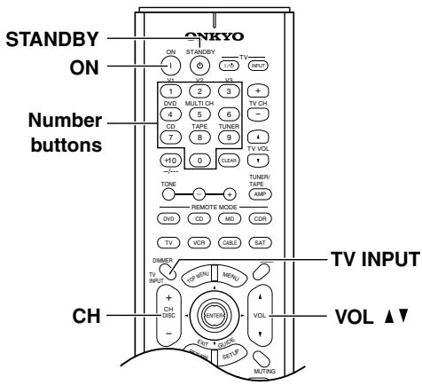
| [ON], [STANDBY] | Set the TV to On or Standby |
| Number buttons | Enter numbers |
| [CH +/-] | Selects channels on the TV |
| [TV INPUT] | Selects the TV's VCR input |
| VOL [▲]/[▼] | Adjusts the TV's volume |
In addition to these buttons, the remote controller has dedicated buttons for controlling a TV, which can be used regardless of which remote controller mode is currently selected (see page 15).
Controlling a Cable Receiver
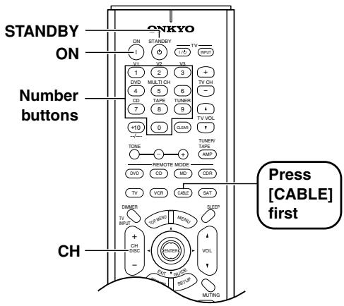
| [ON], [STANDBY] | Set the cable receiver to On or Standby |
| [CH +/-] | Select cable channels |
| Number buttons | Enter numbers |
Controlling a VCR
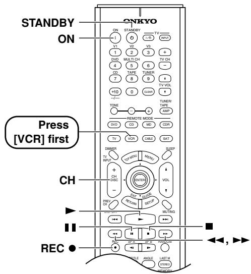
| [ON], [STANDBY] | Set the VCR to On or Standby |
| [CH +/-] | Selects channels on the VCR |
| [►] | Play |
| [■] | Stop |
| [←] | Rewind |
| [►] | Fast forward |
| [■] | Pause |
| REC [●] | Record |
Controlling a Satellite Receiver
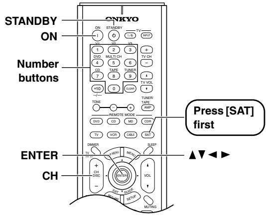
| [ON], [STANDBY] | Set the satellite receiver to On or Standby |
| [CH +/-] | Select satellite channels |
| [▲]/[▼]/[▲][▼] | Select menu items |
| [ENTER] | Confirm selection |
| Number buttons | Enter numbers |
Troubleshooting
| Symptom | Possible cause | Remedy | |
| Power | The HT-R520 shuts down immediately after being turned on? | The amp protection system has been activated. | Contact your Onkyo dealer. |
| Audio | There's no sound coming from the speakers? | The HT-R520 is muted and the MUTING indicator is on. | Unmute the HT-R520 (page 37). |
| The HT-R520 is not connected properly. | Make sure that all audio connecting plugs are pushed in all the way. And make sure that the inputs and outputs of all components are connected properly (page 20). | ||
| If your turntable doesn't have a built-in phono preamp, you must connect one between your turntable and the HT-R520. | |||
| If your turntable uses an MC cartridge, you must use a compatible phono preamp. | |||
| The speaker cables are not connected properly. | Make sure that the polarity of the speaker cables is correct and that the bare wires are in contact with metal part of each speaker terminal (page 17). | ||
| The wrong input source is selected. | Select the correct input source (page 32). | ||
| A pair of headphones are connected. | Disconnect the headphones (page 37). | ||
| The input signal format is set to PCM or DTS. | Set the input signal format to Auto (page 45). | ||
| The volume is set at minimum. | Turn up the volume (page 32). | ||
| The speakers are configured incorrectly. | Specify which speakers are connected (page 48), the speaker distances (page 46) and adjust the individual speaker levels (page 47). | ||
| The source component is not outputting digital audio. | Check the digital audio output setting on the connected device. On some games consoles, such as those that support DVD, the default setting is off. | ||
| A compatible digital audio format is not selected on the source component. | With some DVD-Video discs, you need to select an audio output format from a menu. | ||
| The center speaker is not working or is very quiet? | The Stereo, Direct, or Orchestra listening mode is selected. | The center speaker is not used with these modes (page 40). | |
| The level of the center speaker is set at minimum. | Check the volume of the center speaker (page 47). | ||
| The Center setting is set to None in the Speaker Configuration. | Check the Center setting in the Speaker Configuration (page 48). | ||
| Only the center speaker is working? | You're listening to a mono sound source (e.g., TV or AM broadcast) and the PL II/PL IIx Movie or PL II/PL IIx Music listening mode is selected, so the sound is concentrated in the center speaker. | Select another listening mode (page 39). | |
| The surround speakers are not working? | Selected listening mode doesn't use surround speakers. | When the Stereo or Direct listening mode is selected, the surround speakers produce no sound (page 40). | |
| Surround speaker output depends on the source material, and some material may not use the surround speakers much. | |||
| The level of the surround speaker is set at minimum. | Check the volume of the surround speaker (page 47). | ||
| The Surround setting is set to None in the Speaker Configuration. | Check the Surround setting in the Speaker Configuration (page 48). |
Troubleshooting—Continued
| Symptom | Possible cause | Remedy | |
| Audio | The surround back speakers produce no sound? | The level of the surround back speaker is set at minimum. | Check the volume of the surround back speaker (page 47). |
| The Surround Back setting is set to None in the Speaker Configuration. | Check the Surround Back setting in the Speaker Configuration (page 48). | ||
| The selected listening mode doesn't use the surround back speakers. | Select another listening mode. See page 39 for information on listening modes. | ||
| Surround speaker output depends on the source material, and some material may not use the surround speakers much. | If you're playing a Dolby Digital EX or DTS-ES source, make sure that the Dolby Digital/DTS setting is set to On (page 42). | ||
| A low-frequency noise or hum can be heard? | The audio connecting cables at the rear of the HT-R520 are too close to the power cord. | Untangle the audio cables and position them as far away as possible from the power cord. | |
| The sound is too bright or harsh and the high range is not clear? | The treble is set too high. | Adjust the treble (page 36). | |
| The subwoofer is not working or is very quiet? | The Subwoofer setting is set to No in the Speaker Configuration. | Check the Subwoofer setting in the Speaker Configuration (page 48). | |
| The volume of the subwoofer is set at minimum. | Check the volume of the subwoofer (page 47, 33). | ||
| Speaker set A is turned off. The subwoofer output does not work while only speaker set B is on. | Turn on speaker set A. | ||
| Video | There's no picture on the TV? | The TV's input selector is set incorrectly. | Select the correct input on the TV (i.e., the input to which the HT-R520 is connected). |
| The video input and output are different formats. | The HT-R520 doesn't convert between video formats. It works as a video signal switcher. Composite video input signals are output only by composite video outputs. S-Video input signals are output only by S-Video outputs. And component video input signals are output only by component video outputs. | ||
| Remote controller | The buttons on the HT-R520 work OK but those on the remote controller don't? | The wrong remote controller mode is selected. | Select the correct mode (page 10). |
| The batteries are installed incorrectly. | Check the batteries and correct as necessary (page 9). | ||
| You're not pointing the remote controller at the HT-R520's remote sensor. | Point the remote controller at the HT-R520's remote sensor (page 9). | ||
| Can't use the remote controller with other AV components? | You've connected a MiniDisc recorder or CD recorder to the HT-R520 but haven't changed the TAPE/MD/CDR display. | Press and hold the [TAPE] input selector button until MD or CDR, as appropriate, appears on the display. | |
| The wrong remote control code has been entered. | If more than one code is listed, try each one (page 50). | ||
| With some AV components, certain buttons may not work as expected and some may not work at all. | |||
| You're pointing the remote controller at the wrong AV component. | To control a component connected via R1, point the remote controller at the HT-R520. To control a component that's not connected via R1, point the remote controller at that component. | ||
| You've made an R1 connection but not an analog audio connection (RCA). | To use R1, you must make an R1 connection and an analog audio connection (RCA) between the component and HT-R520, even if they are connected digitally (page 30). |
Troubleshooting—Continued
| Symptom | Possible cause | Remedy | |
| Tuner | Reception is noisy, intermittent, and the FM STE-REO indicator flashes? | You're too far away from the transmitter. Or, your FM antenna is in the wrong position or pointing in the wrong direction. Or, the station's signal strength is poor. | Use the [TUNING MODE] button to select Manual Tuning mode, and tune the station in mono (page 34). |
| Adjust the position, height, and direction of your FM antenna. | |||
| Install an outdoor FM antenna, preferably one with many elements. Installing an outdoor antenna is a specialist job, so contact your nearest dealer for advice (page 19). | |||
| Reception is hindered by a crackling noise? | Interference is being caused by fluorescent lights being turned on or off or by passing cars. | Install an outdoor antenna as far away as possible from nearby roads. | |
| Adjust the position or direction of your outdoor antenna. | |||
| Move your antenna as far away as possible from fluorescent lights. | |||
| AM reception is hindered by a buzzing noise, especially at night or with weak signals? | Interference caused by electrical equipment, including fluorescent lights. | Relocate your AM antenna. | |
| Install an outdoor AM antenna (page 19). | |||
| AM reception is hindered by a high-pitched noise? | Interference caused by your TV. | Move the AM loop antenna as far away as possible from your TV. | |
| Move the HT-R520 as far away as possible from your TV. | |||
| The tuner presets no longer work? | The power cord has not been connected to a wall outlet, or the power has been turned off for an extended period. | Preset your favorite radio stations again (page 35). The power cord must be plugged into a wall outlet a few times each month in order to preserve the preset. | |
| Recording | Sound can be heard from the speakers, but it cannot be recorded? | From the VIDEO 1 OUT, you're trying to record the signal being fed into theVIDEO 1 IN, or from the TAPE OUT, you're trying to record the signal being fed into the TAPE IN. | To prevent signal loops and damage to the HT-R520, input signals are not fed through to outputs with the same name (e.g., TAPE IN/OUT or VIDEO 1 IN/OUT). |
| You're playing Dolby Digital or DTS source material. You cannot record from an AV component that is connected digitally. | Although you cannot record Dolby Digital or DTS surround channels, you can record the left and right channels by connecting the source AV component's analog left and right outputs to a pair of analog inputs on the HT-R520. | ||
| The wrong input source is selected on your recorder. | Select the correct input source. See your recorder's manual for more information. | ||
| Can't record the surround-sound effects produced by the listening modes? | This is normal. The surround-sound effects produced by the listening modes cannot be recorded. | ||
| Others | The Late Night function doesn't work? | The Late Night function only works with Dolby Digital. | "DO DIGITAL" appears on the display when using a Dolby Digital source. |
| The multichannel DVD input doesn't work? | The multichannel input is not selected. | Press the [MULTI CH] button to select the multichannel input (page 33). | |
| The AV component is not properly connected. | Connect the AV component's 5.1-channel outputs to the HT-R520's DVD IN FRONT, SURR, CENTER, and SUBWOOFER sockets (page 24). | ||
| The listening mode changes to Stereo when headphones are connected? | This is normal. When you connect a pair of headphones, the Stereo listening mode is selected automatically. |
Specifications
Amplifier Section
Power output:
All channels:
130 W (8 Ω, 20 Hz-20 kHz, FTC)
Dynamic power:
2 × 260 ~W (3 Ω, front)
2 × 200 ~W (4 Ω, front)
2× 95W (8Ω, front)
THD (total harmonic distortion):
0.08% (rated power)
Damping factor:
60(front,1kHz,8Ω)
Input sensitivity and impedance:
200mV / 47k (LINE)
Output level and impedance:
200 mV/470 Ω (REC OUT)
Frequency response:
10Hz - 100kHz / + 1 dB, -3dB (Direct mode)
Tone control:
± 12 dB, 50Hz (BASS)
± 12 dB, 20,000Hz (TREBLE)
S/N ratio (Direct mode)
100 dB (CD, IHF-A)
Speaker impedance:
6
Video Section
Input sensitivity, output
level and impedance:
1.0 Vp-p/75 Ω (component and S-Video Y)
0.7 Vp-p/75 Ω (component P_B / C_B , PR / CR )
0.28 Vp-p/75 Ω (S-Video C)
1.0 Vp-p/75 Ω (composite)
Component video
frequency response:
5 Hz-50 MHz
Tuner Section
FM
Tuning frequency range: 87.5-108.0 MHz
Usable sensitivity: FM STEREO 17.2 dBf, 2.0 V (75 Ω IHF)
FM MONO 11.2 dBf, 1.0 V (75 Ω IHF)
S/N ratio: FM STEREO 70 dB (IHF-A)
FM MONO 76 dB (IHF-A)
THD: FM STEREO 0.3% (1 kHz)
FM MONO 0.2% (1 kHz)
FM stereo separation: 45dB at 1kHz
■ AM
Tuning frequency range: 530 - 1700kHz
Usable sensitivity: 30 V
S/N ratio: 40 dB
THD: 0.7%
General
Power supply: AC 120 V, 60 Hz
Power consumption: 4.6 A
Standby power
consumption:
2.5 W
Dimensions
(W x H x D): 17-1/8" x 5-7/8" x 14-13/16" (435 x 150 x 376 mm)
Weight: 22.5 lbs. (10.2kg)
Video Inputs
Component video inputs:2 (DVD, Video 1/2/3)
S-Video inputs: 4 (DVD, Video 1-3)
Video inputs: 4 (DVD, Video 1-3)
Video Outputs
Component video
outputs:
1 (Component Video Out)
S-Video outputs:
2 (Video 1 Out, Monitor Out)
Video outputs:
2 (Video 1 Out, Monitor Out)
Audio Inputs
Digital inputs: 4 (Optical 1-3, Coaxial)
6 (CD, Tape, DVD, Video 1-3)
inputs:
5.1 ch (Front L/R, Center, Surround L/R, Subwoofer)
Audio Outputs
Analog outputs: 2 (Tape Out, Video 1 Out)
Subwoofer pre out:
Speaker outputs: 6+2
Phone:
Specifications and features are subject to change without notice.
-
The HT-R520 contains a microcomputer for signal processing and control functions. In very rare situations, severe interference, noise from an external source, or static electricity may cause it to lockup. In the unlikely even that this should happen, unplug the power cord from the wall outlet, wait at least five seconds, and then plug it back in again. That should fix it.
-
To reset the HT-R520 to its factory defaults, turn it on and, while holding down the [VIDEO 1] button, press the [STANDBY/ON] button. "Clear" will appear on the display and the HT-R520 will enter Standby mode.
ONKYO CORPORATION
Sales & Product Planning Div.: 2-1, Nisshin-cho, Neyagawa-shi, OSAKA 572-8540, JAPAN
Tel: 072-831-8023 Fax: 072-831-8124
18 Park Way, Upper Saddle River, N.J. 07458, U.S.A.
Tel: 201-785-2600 Fax: 201-785-2650 http://www.onkyousa.com
ONKYO EUROPE ELECTRONICS GmbH
Liegnitzerstrasse 6, 82194 Groebenzell, GERMANY
Tel: +49-8142-4401-0 Fax: +49-8142-4401-555 http://www.onkyo.net
ONKYO CHINA LIMITED
Units 2102-2107, Metroplaza Tower I, 223 Hing Fong Road, Kwai Chung,
N.T., HONG KONG Tel: 852-2429-3118 Fax: 852-2428-9039
ONKYO
HOMEPAGE
http://www.onkyo.com/
ONKYO®
6.1ch Home Theater Speaker Package
SKS-HT520
HTP-520
SKW-520
POWERED SUBWOOFER
SKF-520F
FRONT SPEAKER
SKC-520C
CENTER SPEAKER
SKM-520S
SURROUND SPEAKER
SKB-520
Important Safety Instructions 2
Precautions. 3
Package Contents. 3
Getting to know Your Speaker Package 4
Installing & Using
Connecting the Speakers. 4
About Home Theater 5
Power Cord Precautions. 6
Adjustment. 6
Appendix
Operating Precautions. 6
Troubleshooting 7
Specifications. 7
Instruction Manual
Thank you for purchasing an Onkyo home theater speaker package. Please read this manual thoroughly before using your new speakers. Following the instructions in this manual will enable you to obtain optimum performance and listening enjoyment from your speaker package.
Please retain this manual for future reference.
WARNING:
TO REDUCE THE RISK OF FIRE OR ELECTRIC SHOCK, DO NOT EXPOSE THIS APPARATUS TO RAIN OR MOISTURE.
CAUTION:
TO REDUCE THE RISK OF ELECTRIC SHOCK, DO NOT REMOVE COVER (OR BACK). NO USER-SERVICEABLE PARTS INSIDE. REFER SERVICING TO QUALIFIED SERVICE PERSONNEL.

WARNING
RISK OF ELECTRIC SHOCK
DO NOT OPEN
AVIS
BISQUE DE CHOC ELECTRQUE
NE PAS OUVB

The lightning flash with arrowhead symbol, within an equilateral triangle, is intended to alert the user to the presence of uninsulated "dangerous voltage" within the product's enclosure that may be of sufficient magnitude to constitute a risk of electric shock to persons.

The exclamation point within an equilateral triangle is intended to alert the user to the presence of important operating and maintenance (servicing) instructions in the literature accompanying the appliance.
Important Safety Instructions
-
Read these instructions.
-
Keep these instructions.
-
Heed all warnings.
-
Follow all instructions.
-
Do not use this apparatus near water.
-
Clean only with dry cloth.
-
Do not block any ventilation openings. Install in accordance with the manufacturer's instructions.
-
Do not install near any heat sources such as radiators, heat registers, stoves, or other apparatus (including amplifiers) that produce heat.
-
Do not defeat the safety purpose of the polarized or grounding-type plug. A polarized plug has two blades with one wider than the other. A grounding type plug has two blades and a third grounding prong. The wide blade or the third prong are provided for your safety. If the provided plug does not fit into your outlet, consult an electrician for replacement of the obsolete outlet.
-
Protect the power cord from being walked on or pinched particularly at plugs, convenience receptacles, and the point where they exit from the apparatus.
-
Only use attachments/accessories specified by the manufacturer.
-
Use only with the cart, stand, tripod, bracket, or table specified by the manufacturer, or sold with the apparatus. When a cart is used, use caution when moving the cart/ apparatus combination to avoid injury from tip-over.
PORTABLE CART WARNING

S3125A
-
Unplug this apparatus during lightning storms or when unused for long periods of time.
-
Refer all servicing to qualified service personnel. Servicing is required when the apparatus has been damaged in any way, such as power-supply cord or plug is damaged, liquid has been spilled or objects have fallen into the apparatus, the apparatus has been exposed to rain or moisture, does not operate normally, or has been dropped.
-
Damage Requiring Service
Unplug the apparatus from the wall outlet and refer servicing to qualified service personnel under the following conditions:
A. When the power-supply cord or plug is damaged,
B. If liquid has been spilled, or objects have fallen into the apparatus,
C. If the apparatus has been exposed to rain or water,
D. If the apparatus does not operate normally by following the operating instructions. Adjust only those controls that are covered by the operating instructions as an improper adjustment of other controls may result in damage and will often require extensive work by a qualified technician to restore the apparatus to its normal operation,
E. If the apparatus has been dropped or damaged in any way, and
F. When the apparatus exhibits a distinct change in performance this indicates a need for service.
- Object and Liquid Entry
Never push objects of any kind into the apparatus through openings as they may touch dangerous voltage points or short-out parts that could result in a fire or electric shock.
The apparatus shall not be exposed to dripping or splashing and no objects filled with liquids, such as vases shall be placed on the apparatus.
Don't put candles or other burning objects on top of this unit.
- Batteries
Always consider the environmental issues and follow local regulations when disposing of batteries.
- If you install the apparatus in a built-in installation, such as a bookcase or rack, ensure that there is adequate ventilation.
Leave 20cm (8") of free space at the top and sides and 10cm (4") at the rear. The rear edge of the shelf or board above the apparatus shall be set 10cm (4") away from the rear panel or wall, creating a flue-like gap for warm air to escape.
Precautions
1. AC Fuse
The fuse is located inside the chassis and is not userserviceable. If power does not come on, contact your Onkyo authorized service station.
2. Care
From time to time you should wipe off the front and rear panels and the cabinet with a soft cloth. For heavier dirt, dampen a soft cloth in a weak solution of mild detergent and water, wring it out dry, and wipe off the dirt. Following this, dry immediately with a clean cloth. Do not use rough material, thinners, alcohol or other chemical solvents or cloths since these may damage the finish or remove the panel lettering.
Use a vacuum cleaner to remove dust from hard-to-reach grilles.
3. Power
WARNING
BEFORE PLUGGING IN THE UNIT FOR THE FIRST TIME, READ THE FOLLOWING SECTION CAREFULLY.
The voltage of the available power supply differs according to country or region. Be sure that the power supply voltage of the area where this unit will be used meets the required voltage (e.g., AC 120 V, 60 Hz) written on the rear panel.
Auto standby function does not fully shutdown the SKW-520. If you do not intend to use the SKW-520, remove the power cord from the AC outlet.
For Canadian models
For models having a power cord with a polarized plug:
CAUTION: TO PREVENT ELECTRIC SHOCK, MATCH WIDE BLADE OF PLUG TO WIDE SLOT, FULLY INSERT.
Make sure your box contains all of the items below. If anything is missing, contact the nearest Onkyo dealer.
- Front speakers (SKF-520F)
Center speaker (SKC-520C)
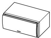
- Speaker cable for front speakers 15 ft. (4.5m)
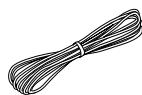
(Red)
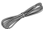
(White)
- Speaker cable for center speaker 10 ft. (3 m)

(Green)
- Surround speakers (SKM-520S/SKB-520)
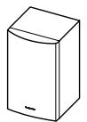
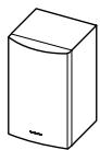
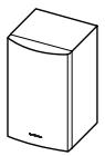
- Speaker cables for surround speakers 30 ft. (9 m)
(Blue)

(Gray)

(Brown)
- Subwoofer (SKW-520)
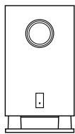
- RCA cable for subwoofer connection
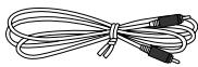
The alphabet displayed at the end of the product name found in catalogs and on package represents the color of the system. Though the color varies, the specifications and operations are the same.
■ Attaching and detaching the speaker grilles
Front and Center spakers have detachable grilles. Use the following method to attach or detach the grilles.
- While holding the bottom edge of the speaker grille with your both hands, pull it gently toward you to remove the bottom of the grille.
- In the same way, gently pull the upper edge of the speaker grille toward you to remove it from the main unit.
- To replace the grill, push the projections at the corners into the grille plug holes on the speaker cabinet.
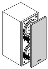
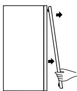
Removal
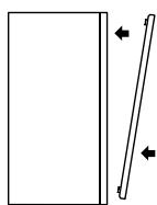
Replacement
Getting to know Your Speaker Package
Subwoofer (SKW-520)
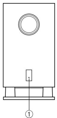
Front
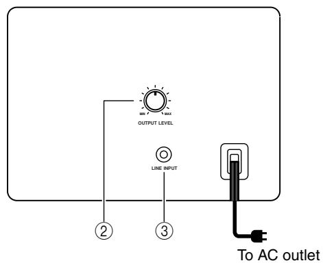
Rear
① STANDBY/ON indicator
Red: Subwoofer in standby mode
Green: Subwoofer on
With the Auto Standby function, the SKW-520 automatically turns on when an input signal is detected in Standby mode. When there's no input signal for a while, the SKW-520 automatically enters Standby mode.
② OUTPUT LEVEL control
This control is used to adjust the volume of the subwoofer.
③ LINE INPUT
This RCA input should be connected to the subwoofer pre out on your AV receiver, amp, or other receiver with supplied RCA cable.
If you are also using the HT-R520:
Connect this input to the subwoofer pre out of the HT-R520.
Note:
The Auto Standby function turns the subwoofer on when the input signal exceeds a certain level. If the Auto Standby function does not work reliably, try slightly increasing or decreasing the subwoofer output level on your receiver or amp.
Connecting the Speakers
Read the following before connecting your speakers:
- Turn off your amp before making any connections.
- Pay close attention to speaker wiring polarity. Connect positive (+) terminals to only positive (+) terminals, and negative (-) terminals to only negative (-) terminals. If the speakers are wired incorrectly, the sound will be out of phase and will sound unnatural.
- Be careful not to short the positive and negative wires. Doing so may damage your amp.
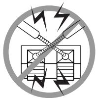
Connecting the Speaker Cables
1 Use the supplied cables to connect each speaker's input terminals to the corresponding speaker output terminals on your AV receiver.
Match the color of each cable to the corresponding speaker terminal.
To make a connection, while pressing the terminal lever, insert the wire into the hole, and then release the lever.
Make sure that the terminals are gripping the bare wires, not the insulation.
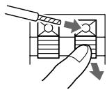
Connecting the Subwoofer
Using the supplied RCA cable, connect the subwoofer's LINE INPUT to your AV receiver's SUBWOOFER PRE OUT.
Example, adding the HT-R520:
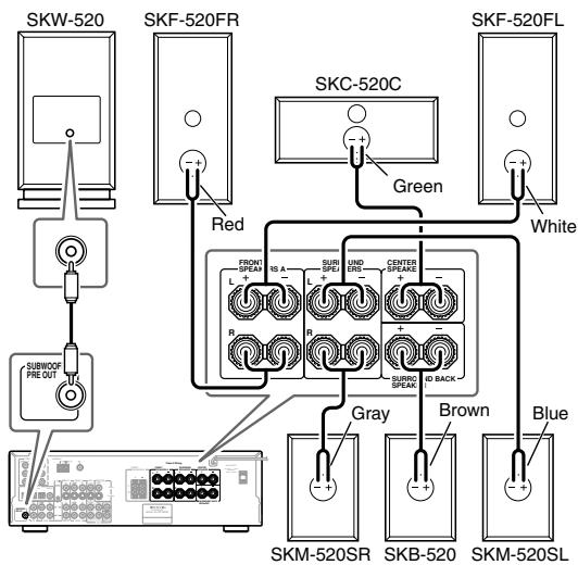
About Home Theater
Enjoying Home Theater
The Home Theater means that you can enjoy surround sound with a real sense of movement in your own home—just like being in a movie theater or concert hall.
Front left and right speakers
These output the overall sound. Their role in a home theater is to provide a solid anchor for the sound image. They should be positioned facing the listener at about ear level, and equidistant from the TV. Angle them inward so as to create a triangle, with the listener at the apex.
Center speaker
This speaker enhances the front left and right speakers, making sound movements distinct and providing a full sound image. In movies it's used mainly for dialog.
Position it close to your TV facing forward at about ear level, or at the same height as the front left and right speakers.
Put it somewhere where it won't slide around or fall.
Surround back speaker
This speaker further enhances the realism of surround sound and improves sound localization behind the listener. Position it behind the listener about 2-3 feet (60-100 cm) above ear level. Make sure that the listening position is within the range of the speaker.
Subwoofer
The subwoofer handles the bass sounds of the LFE (Low-Frequency Effects) channel. The volume and quality of the bass output from your subwoofer will depend on its position, the shape of your listening room, and your listening position. In general, a good bass sound can be obtained by installing the subwoofer in a front corner, or at one-third the width of the wall, as shown.
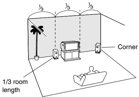
Surround left and right speakers
These speakers are used for precise sound positioning and to add realistic ambience. Position them at the sides of the listener, or slightly behind, about 2-3 feet (60-100 cm) above ear level. Ideally they should be equidistant from the listener.
Wall-mounting the surround speakers
If the surround speakers are to be wall-mounted, make sure that the walls are strong enough to support the speaker's weight. The weight that mounting screws can support varies greatly depending on the wall material and the position of the reinforcing ribs embedded in the wall.
Use long screws with a head diameter of 1/4 inch
(6.3 mm) or less and a shank diameter of 1/8 inch
(3.5 mm) or less. (We recommend that you consult a home installation professional.)
Power Cord Precautions
- Before connecting the power cord, connect all of your speakers and AV components.
- Turning on the SKW-520 may cause a momentary power surge that might interfere with other electrical equipment on the same circuit. If this is a problem, plug the SKW-520 into a different branch circuit.
Adjustment
Setting the Subwoofer Level
To set the level of the subwoofer, use the OUTPUT LEVEL control. Set it so that bass sounds are evenly balanced with the treble sounds from the other speakers. Because our ears are less sensitive to very low bass sounds, there's a temptation to set the level of the subwoofer too high. As a rule of thumb, set the subwoofer level to what you think is the optimal level, and then back it off slightly.
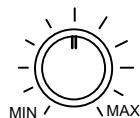
OUTPUT LEVEL
Operating Precautions
Placement
- The speaker cabinets are made out of wood and are therefore sensitive to extreme temperatures and humidity, do not put them in locations subject to direct sunlight or in humid places, such as near an air conditioner, humidifier, bathroom, or kitchen.
- Do not put water or other liquids close to the speakers. If liquid is spilled over the speakers, the drive units may be damaged.
- Speakers should only be placed on sturdy, flat surfaces that are free from vibration. Putting them on uneven or unstable surfaces, where they may fall and cause damage, will affect the sound quality.
- Subwoofer is designed to be used in the upright vertical position only. Do not use it in the horizontal or tilted position.
- If the unit is used near a turntable or CD player, howling or slipping of sound may occur. To prevent this, move the unit away from the turntable or CD player otherwise lower the unit's output level.
Using Close to a TV or Computer
TVs and computer monitors are magnetically sensitive devices and as such are likely to suffer discoloration or picture distortion when conventional speakers are placed nearby. To prevent this, the SKF-520F and SKC-520C feature internal magnetic shielding. In some situations, however, discoloration may still be an issue, in which case you should turn off your TV or monitor, wait 15 to 30 minutes, and then turn it back on again. This normally activates the degaussing function, which neutralizes the magnetic field, thereby removing any discoloration effects. If discoloration problems persist, try moving the speakers away from your TV or monitor. Note that discoloration can also be caused by a magnet or demagnetizing tool that's too close to your TV or monitor.
Input Signal Warning
The speakers can handle the specified input power when used for normal music reproduction. If any of the following signals are fed to them, even if the input power is within the specified rating, excessive current may flow in the speaker coils, causing burning or wire breakage:
- Interstation noise from an untuned FM radio.
- Sound from fast-forwarding a cassette tape.
- High-pitched sounds generated by an oscillator, electronic musical instrument, and so on.
- Amplifier oscillation.
- Special test tones from audio test CDs and so on.
- Thumps and clicks caused by connecting or disconnecting audio cables (Always turn off your amplifier before connecting or disconnecting cables.)
- Microphone feedback.
Troubleshooting
| Symptom | Possible cause | Remedy |
| There's no sound coming from certain speakers? | The speaker cables are not connected properly. | Check the speaker cables and correct as necessary. |
| The speaker configuration is not set correctly. | Check the speaker configuration. | |
| The subwoofer does not turn on? | The power plug is not fully inserted into the wall outlet. | Insert the power plug fully into the wall outlet. |
| The subwoofer produces no sound? | The OUTPUT LEVEL control is set to minimum. | Turn up the OUTPUT LEVEL control. |
| The RCA cable is not properly connected to the subwoofer's LINE INPUT. | Make sure that the RCA cable is properly connected to the subwoofer's LINE INPUT. | |
| The level of the input signal was too low and the subwoofer entered Standby mode. | Slightly increase the subwoofer pre out output level on your AV receiver. | |
| The Subwoofer configuration is not set correctly. For HT-R520 speaker package: The subwoofer setting is set to No in the speaker configuration on the HT-R520. | Check the subwoofer setting in the speaker configura-tion on your AV receiver. | |
| The subwoofer produces hardly any sound? | The source material contain little or no bass content. | Choose source material with more bass content. |
| A humming sound can be heard from the sub-woofer? | The RCA cable is not properly connected to the subwoofer's LINE INPUT. | Make sure that the RCA cable is properly connected to the subwoofer's LINE INPUT. |
| External interference from a TV or other elec-tronic device is being picked up. | Move the subwoofer and RCA cable away from the interference source. Make sure your audio system is grounded properly. |
Specifications
■ Powered Subwoofer (SKW-520)
Type:
Input sensitivity/impedance:
Maximum output power:
Frequency response:
Cabinet capacity:
Dimensions (W× H× D)
Weight:
Drivers unit:
Power supply:
Power consumption:
Other:
Bass-reflex
330 mV / 100 kΩ
220 W (Dynamic Power)
25 Hz-150 Hz
1.35 cubic feet (38.5 L)
10-13/16"×20-3/8"×16-3/16"
(275× 518× 411mm)
30 lbs. (13.6 kg)
10 inch Cone Woofer
AC 120 V, 60 Hz
150W
Auto Standby function
■ Front Speaker (SKF-520F)
Type:
Impedance:
Maximum input power:
Output sound pressure level:
Frequency response:
Crossover frequency:
Cabinet capacity:
Dimensions (W× H× D)
Weight:
Drivers unit:
2 Way Bass-reflex
8Ω
130W
87 dB/W/m
55 Hz-50 kHz
4.5 kHz
0.38 cubic feet (10.8 L)
7-7/16"×16-1/2"×9-5/16"
(189× 419× 236mm)
12.1 lbs. (5.5 kg)
5-1/4 inch OMF Cone
Woofer × 2
1 inch Balanced Dome
Color-coded push type
Magnetic shielding
Center Speaker (SKC-520C)
Type:
Impedance:
Maximum input power:
Output sound pressure level:
Frequency response:
Crossover frequency:
Cabinet capacity:
Dimensions (W× H× D)
Weight:
Speaker:
Terminal:
Other:
2 Way Bass-reflex
8Ω
130W
85 dB/W/m
60 Hz-50 kHz
4.5 kHz
0.27 cubic feet (7.7 L)
15-1/4"×6-3/16"×7-15/16"
(387× 157× 202mm)
8.2 lbs. (3.7 kg)
4 inch OMF Cone Woofer
X2
1 inch Balanced Dome
Color-coded push type
Magnetic shielding
Surround Speaker (SKM-520S/SKB-520)
Type:
Impedance:
Maximum input power:
Output sound pressure level:
Frequency response:
Crossover frequency:
Cabinet capacity:
Dimensions (W× H× D)
Weight:
Speaker:
Terminal:
2 Way Bass Reflex
8Ω
130W
82 dB/W/m
60 Hz-50 kHz
5 kHz
0.09 cubic feet (2.7 L)
6-7/8"×10-7/16"×4-15/16"
(175× 265× 125mm)
3.7 lbs. (1.7 kg)
4 inch Cone Woofer
1 inch Balanced Dome
Color-coded push type
Specifications and appearance are subject to change without prior notice.
ONKYO CORPORATION
Sales & Product Planning Div.: 2-1, Nisshin-cho, Neyagawa-shi, OSAKA 572-8540, JAPAN
Tel: 072-831-8023 Fax: 072-831-8124
18 Park Way, Upper Saddle River, N.J. 07458, U.S.A.
Tel: 201-785-2600 Fax: 201-785-2650 http://www.onkyousa.com
ONKYO EUROPE ELECTRONICS GmbH
Liegnitzerstrasse 6, 82194 Groebenzell, GERMANY
Tel: +49-8142-4401-0 Fax: +49-8142-4401-555 http://www.onkyo.net
ONKYO CHINA LIMITED
Units 2102-2107, Metroplaza Tower I, 223 Hing Fong Road, Kwai Chung,
N.T., HONG KONG Tel: 852-2429-3118 Fax: 852-2428-9039
ONKYO
HOMEPAGE
http://www.onkyo.com/
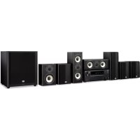
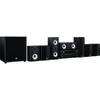
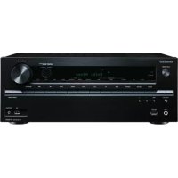
- Contents
- Basic Operation
- WARNING:
- CAUTION:
- WARNING
- AVIS
- Important Safety Instructions
- Precautions
- Power Warning
- Memory backup
- For U.S. models
- Note to CATV system installer:
- FCC Information for User
- NOTE:
- For Canadian Models
- Modèle canadien
- Supplied Accessories
- Features
- Amp
- Processing
- Audio/Video
- FM/AM Tuner
- Remote Controller
- Table of Contents
- Introduction
- Connection
- Enjoying the listening Modes
- Advanced Operation
- Front & Rear Panels
- Front Panel
- Front & Rear Panels—Continued
- Display
- Rear Panel
- Before Using the HT-R520
- Installing the Batteries
- Notes:
- Using the Remote Controller
- How to Use the Remote Controller
- ■ AMP/TUNER & TAPE Mode
- DVD, CD, MD & CDR Modes
- TV, VCR, CABLE & SAT Modes
- AMP/TUNER Mode
- Remote Controller—Continued
- SURR button
- ALL ST button
- STEREO button
- DIRECT button
- DVD Mode
- CD Mode
- MD Mode & CDR Mode
- ① ON button
- ② Number buttons
- ③ DISPLAY button
- ④ Play [▶] button
- ⑤ Previous & Next [▶]按钮
- ⑥ Pause [I] button
- ⑦ REC [●] button
- ⑧ REPEAT button
- ⑨ OPEN/CLOSE [▲] button
- CLEAR button
- VOL button
- MUTING button
- Tape Mode
- TV Control Buttons
- Connecting Your Speakers
- Enjoying Home Theater
- Front left and right speakers
- Surround back speaker
- Center speaker
- Subwoofer
- Surround left and right speakers
- Speaker Configuration
- Connecting Your Speakers—Continued
- Connecting speaker Set A
- Unscrew the terminal. Fully insert the wire. Screw the terminal tight.
- Connecting Speaker Set B
- Connecting Antenna
- Connecting the Indoor FM Antenna
- Attach the FM antenna, as shown.
- Use thumbtacks or something similar to fix the FM antenna into position.
- Connecting the AM Loop Antenna
- Assemble the AM loop antenna, inserting the tabs into the base, as shown.
- Connect both wires of the AM loop antenna to the AM push terminals, as shown.
- Connecting Antenna—Continued
- Connecting an Outdoor FM Antenna
- Using a TV/FM Antenna Splitter
- Connecting an Outdoor AM Antenna
- Connecting the HT-R520
- Before Making Any Connections
- Optical Digital Inputs
- RCA AV Connection Color Coding
- AV Cables & Sockets
- Connecting the HT-R520—Continued
- Connection Guide
- Inputs
- Outputs (for recording)
- ■ MONITOR OUT
- Which Connections Should I Use?
- Video Connection Formats
- Audio Connection Formats
- Connecting Your TV or Projector
- Monitor Out
- Using Composite Video
- Using S-Video
- Using Component Video
- Audio Connections
- Using a Coaxial or Optical Connection
- Using Analog Connections
- Connecting a DVD player
- Video Connections
- OR
- DVD Multichannel Connection
- Connecting a VCR for Playback
- Connecting a VCR for Recording
- Connecting Other Video Sources—Satellite, Cable, Set-top box, LD Player, etc.
- Connecting a Camcorder, Games Console, etc.
- Connecting a CD Player
- Connecting a Cassette Recorder
- Connecting a DAT, CD, or MiniDisc Recorder
- Using a Coaxial or Optical Connection (playback only)
- Connecting a Turntable
- Turntable with a Built-in Phono Preamp
- Turntable without a Built-in Phono Preamp
- Turntable with an MC (Moving Coil) Cartridge
- Connecting Onkyo R1 Components
- Auto Power On/Standby
- Direct Change
- Remote Control
- Connecting the Power Cords of Other Components
- Connecting the Power Cord
- Turning On & First Time Setup
- Turning On the HT-R520
- Changing the TAPE/MD/CDR Display
- Assigning the Digital Inputs to Input Sources
- Playing Your AV Components
- Selecting the Source Component
- Playing Your AV Components—Continued
- Displaying Source Information
- Interpreting Surround Channel Information
- Using the Multichannel Input
- Using the Tuner
- Listening to the Radio
- Tuning into Radio Stations
- Auto Tuning Mode
- Manual Tuning Mode
- Tuning into weak FM stations
- Using the Tuner—Continued
- Common Functions
- Using the OptiResponse Equalizer
- Setting the Display Brightness
- Adjusting the Bass & Treble
- Bass
- Treble
- Common Functions—Continued
- Muting the HT-R520
- Press the remote controller's [MUTING] button.
- Adjusting Speaker Levels Temporarily
- Use the remote controller's [CH SEL] button to select each speaker, and use the [LEVEL-] and [LEVEL+] buttons to adjust the volume.
- Using the Sleep Timer
- Press the [SLEEP] button repeatedly to select the required sleep time.
- Using Headphones
- Using the Listening Modes
- Using the Listening Modes—Continued
- Selecting Listening Modes
- Selecting on the HT-R520
- [STEREO] button
- LISTENING MODE [←] [▶] buttons
- Selecting with the Remote Controller
- [DIRECT] button
- [SURR] button
- [DSP] & [DSP▶] buttons
- [All ST] button
- About the Listing Modes
- Basic Modes
- Surround Modes
- DTS-ES
- DTS+Neo:6
- DTS+Dolby EX
- Onkyo Original DSP Modes
- Orchestra
- Unplugged
- Studio-Mix
- TV Logic
- All Ch Ste
- Dolby Digital/DTS setting (5.1 or 6.1-channel playback)
- Dolby Digital Setting
- DTS Setting
- Recording
- Recording the Input Source
- Recording from Different AV Sources
- Advanced Function
- Using the Audio Adjust Functions
- Double Bass
- Late Night (Dolby Digital only)
- CinemaFILTER
- Adjusting the DTS Neo:6 Music Mode
- Center Image
- Advanced Function—Continued
- Adjusting the PL II or PL IIx Music Mode
- Panorama
- Dimension
- Center Width
- Digital Input Signal Formats
- Advanced Setup
- Speaker Distance
- Advanced Setup—Continued
- Speaker Levels
- Crossover Frequency
- Controlling Other Components
- Entering Remote Control Codes
- Codes for Onkyo DVD Players
- Resetting the [DVD], [CD], [MD] or [CDR] Mode Button
- Resetting the Remote Controller
- Controlling Other Components—Continued
- Remote Control Codes
- Controlling a TV
- Controlling a Cable Receiver
- Controlling a VCR
- Controlling a Satellite Receiver
- Troubleshooting—Continued
- Specifications
- Amplifier Section
- Video Section
- Tuner Section
- FM
- ■ AM
- General
- Video Inputs
- Video Outputs
- Audio Inputs
- Audio Outputs
- ONKYO CORPORATION
- ONKYO®
- 6.1ch Home Theater Speaker Package
- SKS-HT520
- HTP-520
- Installing & Using
- Appendix
- Instruction Manual
- AC Fuse
- Care
- Power
- ■ Attaching and detaching the speaker grilles
- Getting to know Your Speaker Package
- Subwoofer (SKW-520)
- ① STANDBY/ON indicator
- ② OUTPUT LEVEL control
- ③ LINE INPUT
- Connecting the Speakers
- Connecting the Speaker Cables
- Use the supplied cables to connect each speaker's input terminals to the corresponding speaker output terminals on your AV receiver.
- Connecting the Subwoofer
- Using the supplied RCA cable, connect the subwoofer's LINE INPUT to your AV receiver's SUBWOOFER PRE OUT.
- About Home Theater
- Wall-mounting the surround speakers
- Power Cord Precautions
- Adjustment
- Setting the Subwoofer Level
- Operating Precautions
- Placement
- Using Close to a TV or Computer
- Input Signal Warning
- Troubleshooting
- ■ Powered Subwoofer (SKW-520)
- ■ Front Speaker (SKF-520F)
- Center Speaker (SKC-520C)
- Surround Speaker (SKM-520S/SKB-520)
Brand : ONKYO
Model : HT-S770
Category : Home theater audio system