
HT-S3105 - Home theater audio system ONKYO - Free user manual and instructions
Find the device manual for free HT-S3105 ONKYO in PDF.

| Product Type | 5.1 Home Cinema Audio System |
| Brand | ONKYO |
| Model | HT-S3105 |
| Receiver Dimensions (W x H x D) | 435 x 150 x 320 mm |
| Receiver Weight | 8.0 kg |
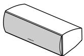
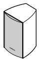
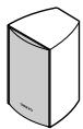
| Front Speaker Dimensions (W x H x D) | 155 x 250 x 125 mm |
| Front Speaker Weight | 2.0 kg |
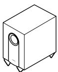
| Subwoofer Dimensions (W x H x D) | 230 x 410 x 340 mm |
| Subwoofer Weight | 7.5 kg |
| Power Supply | 220-240V AC, 50/60 Hz |
| Power Consumption | 450 W (max) |
| Output Power | 100 W per channel (6 ohms, 1 kHz) |
| Number of Channels | 5.1 |
| Connectivity | HDMI inputs (2), optical, coaxial, analog; subwoofer output |
| Supported Audio Formats | Dolby TrueHD, DTS-HD Master Audio |
| Main Functions | Home cinema amplifier, HD audio decoder, speaker calibration, listening modes |
| Maintenance and Cleaning | Wipe with a soft dry cloth. Do not use solvents. |
| Safety | Unplug before cleaning. Do not expose to moisture. Use only on a stable surface. |
| Spare Parts and Repairability | Contact an ONKYO authorized service center for repairs. Parts available on request. |
| General Information | User manual available for free download at notice-facile.com |
Frequently Asked Questions - HT-S3105 ONKYO
User questions about HT-S3105 ONKYO
0 question about this device. Answer the ones you know or ask your own.
Ask a new question about this device
Download the instructions for your Home theater audio system in PDF format for free! Find your manual HT-S3105 - ONKYO and take your electronic device back in hand. On this page are published all the documents necessary for the use of your device. HT-S3105 by ONKYO.
USER MANUAL HT-S3105 ONKYO
5.1ch Home Theater System
HT-S3100
HT-S3105
AV Receiver (HT-R340)
Speaker Package
HTP-360 (North American and Asian models)
HTP-318 (European models)
Instruction Manual
Thank you for purchasing an Onkyo 5.1ch Home Theater System. Please read this manual thoroughly before making connections and plugging in the unit. Following the instructions in this manual will enable you to obtain optimum performance and listening enjoyment from your new 5.1ch Home Theater System.
Please retain this manual for future reference.
Contents
Introduction 2
Connection 20
Turning On & First Time Setup.....37
Basic Operation
Playing your AV components.....39
Using the Tuner. 41
Enjoying the Listening Modes.....49
Advanced Operation 51
Troubleshooting 58
Specifications. 62
WARNING:
TO REDUCE THE RISK OF FIRE OR ELECTRIC SHOCK, DO NOT EXPOSE THIS APPARATUS TO RAIN OR MOISTURE.
CAUTION:
TO REDUCE THE RISK OF ELECTRIC SHOCK, DO NOT REMOVE COVER (OR BACK). NO USER-SERVICEABLE PARTS INSIDE. REFER SERVICING TO QUALIFIED SERVICE PERSONNEL.

WARNING
RISK OF ELECTRIC SHOCK
DO NOT OPEN
AVIS
RISQUE DE CHOC ELECTRIQUE
NE PAS OUVIR


The lightning flash with arrowhead symbol, within an equilateral triangle, is intended to alert the user to the presence of uninsulated "dangerous voltage" within the product's enclosure that may be of sufficient magnitude to constitute a risk of electric shock to persons.

The exclamation point within an equilateral triangle is intended to alert the user to the presence of important operating and maintenance (servicing) instructions in the literature accompanying the appliance.
Important Safety Instructions
-
Read these instructions.
-
Keep these instructions.
-
Heed all warnings.
-
Follow all instructions.
-
Do not use this apparatus near water.
-
Clean only with dry cloth.
-
Do not block any ventilation openings. Install in accordance with the manufacturer's instructions.
-
Do not install near any heat sources such as radiators, heat registers, stoves, or other apparatus (including amplifiers) that produce heat.
-
Do not defeat the safety purpose of the polarized or grounding-type plug. A polarized plug has two blades with one wider than the other. A grounding type plug has two blades and a third grounding prong. The wide blade or the third prong are provided for your safety. If the provided plug does not fit into your outlet, consult an electrician for replacement of the obsolete outlet.
-
Protect the power cord from being walked on or pinched particularly at plugs, convenience receptacles, and the point where they exit from the apparatus.
-
Only use attachments/accessories specified by the manufacturer.
-
Use only with the cart, stand, tripod, bracket, or table specified by the manufacturer, or sold with the apparatus. When a cart is used, use caution when moving the cart/ apparatus combination to avoid injury from tip-over.
PORTABLE CART WARNING

S3125A
- Unplug this apparatus during lightning storms or when unused for long periods of time.
-
Refer all servicing to qualified service personnel. Servicing is required when the apparatus has been damaged in any way, such as power-supply cord or plug is damaged, liquid has been spilled or objects have fallen into the apparatus, the apparatus has been exposed to rain or moisture, does not operate normally, or has been dropped.
-
Damage Requiring Service
Unplug the apparatus from the wall outlet and refer servicing to qualified service personnel under the following conditions:
A. When the power-supply cord or plug is damaged,
B. If liquid has been spilled, or objects have fallen into the apparatus,
C. If the apparatus has been exposed to rain or water,
D. If the apparatus does not operate normally by following the operating instructions. Adjust only those controls that are covered by the operating instructions as an improper adjustment of other controls may result in damage and will often require extensive work by a qualified technician to restore the apparatus to its normal operation,
E. If the apparatus has been dropped or damaged in any way, and
F. When the apparatus exhibits a distinct change in performance this indicates a need for service.
- Object and Liquid Entry
Never push objects of any kind into the apparatus through openings as they may touch dangerous voltage points or short-out parts that could result in a fire or electric shock.
The apparatus shall not be exposed to dripping or splashing and no objects filled with liquids, such as vases shall be placed on the apparatus.
Don't put candles or other burning objects on top of this unit.
- Batteries
Always consider the environmental issues and follow local regulations when disposing of batteries.
- If you install the apparatus in a built-in installation, such as a bookcase or rack, ensure that there is adequate ventilation.
Leave 20cm (8") of free space at the top and sides and 10cm (4") at the rear. The rear edge of the shelf or board above the apparatus shall be set 10cm (4") away from the rear panel or wall, creating a flue-like gap for warm air to escape.
-
Recording Copyright—Unless it's for personal use only, recording copyrighted material is illegal without the permission of the copyright holder.
-
AC Fuse—The AC fuse inside the unit is not user-serviceable. If you cannot turn on the unit, contact your Onkyo dealer.
-
Care—Occasionally you should dust the unit all over with a soft cloth. For stubborn stains, use a soft cloth dampened with a weak solution of mild detergent and water. Dry the unit immediately afterwards with a clean cloth. Don't use abrasive cloths, thinners, alcohol, or other chemical solvents, because they may damage the finish or remove the panel lettering.
4. Power Warning
BEFORE PLugging IN THE UNIT FOR THE FIRST TIME, READ THE FOLLOWING SECTION CAREFULLY.
AC outlet voltages vary from country to country. Make sure that the voltage in your area meets the voltage requirements printed on the unit's rear panel (e.g., AC 230-240 V, 50 Hz or AC 120 V, 60 Hz).
The power cord plug is used to disconnect this unit from the AC power source. Make sure that the plug is readily operable (easily accessible) at all times.
Some models have a voltage selector switch for compatibility with power systems around the world. Before you plug in such a model, make sure that the voltage selector is set to the correct voltage for your area.
Pressing the [STANDBY/ON] button to select Standby mode does not fully shutdown the unit. If you do not intend to use the unit for an extended period, remove the power cord from the AC outlet.
- Never Touch this Unit with Wet Hands—Never handle this unit or its power cord while your hands are wet or damp. If water or any other liquid gets inside this unit, have it checked by your Onkyo dealer.
6. Handling Notes
- If you need to transport this unit, use the original packaging to pack it how it was when you originally bought it.
- Do not leave rubber or plastic items on this unit for a long time, because they may leave marks on the case.
- This unit's top and rear panels may get warm after prolonged use. This is normal.
- If you do not use this unit for a long time, it may not work properly the next time you turn it on, so be sure to use it occasionally.
For U.S. models
FCC Information for User
CAUTION:
The user changes or modifications not expressly approved by the party responsible for compliance could void the user's authority to operate the equipment.
NOTE:
This equipment has been tested and found to comply with the limits for a Class B digital device, pursuant to Part 15 of the FCC Rules. These limits are designed to provide reasonable protection against harmful interference in a residential installation.
This equipment generates, uses and can radiate radio frequency energy and, if not installed and used in accordance with the instructions, may cause harmful interference to radio communications. However, there is no guarantee that interference will not occur in a particular installation. If this equipment does cause harmful interference to radio or television reception, which can be determined by turning the equipment off and on, the user is encouraged to try to correct the interference by one or more of the following measures:
Reorient or relocate the receiving antenna.
- Increase the separation between the equipment and receiver.
- Connect the equipment into an outlet on a circuit different from that to which the receiver is connected.
- Consult the dealer or an experienced radio/TV technician for help.
For Canadian Models
NOTE: THIS CLASS B DIGITAL APPARATUS COMPLIES WITH CANADIAN ICES-003.
For models having a power cord with a polarized plug: CAUTION: TO PREVENT ELECTRIC SHOCK, MATCH WIDE BLADE OF PLUG TO WIDE SLOT, FULLY INSERT.
Replacement and mounting of an AC plug on the power supply cord of this unit should be performed only by qualified service personnel.
IMPORTANT
The wires in the mains lead are coloured in accordance with the following code:
Blue: Neutral
Brown: Live
As the colours of the wires in the mains lead of this apparatus may not correspond with the coloured markings identifying the terminals in your plug, proceed as follows:
The wire which is coloured blue must be connected to the terminal which is marked with the letter N or coloured black.
The wire which is coloured brown must be connected to the terminal which is marked with the letter L or coloured red.
IMPORTANT
The plug is fitted with an appropriate fuse. If the fuse needs to be replaced, the replacement fuse must approved by ASTA or BSI to BS1362 and have the same ampere rating as that indicated on the plug. Check for the ASTA mark or the BSI mark on the body of the fuse. If the power cord's plug is not suitable for your socket outlets, cut it off and fit a suitable plug. Fit a suitable fuse in the plug.
For European Models
Declaration of Conformity
We, ONKYO EUROPE ELECTRONICS GmbH LIEGNITZERSTRASSE 6, 82194 GROEBENZELL, GERMANY

declare in own responsibility, that the ONKYO product described in this instruction manual is in compliance with the corresponding technical standards such as EN60065, EN55013, EN55020 and EN61000-3-2, -3-3.
GROEBENZELL, GERMANY

ONKYO EUROPE ELECTRONICS GmbH
Memory Backup
The AV receiver uses a battery-less memory backup system in order to retain radio presets and other settings when it's unplugged or in the case of a power failure. Although no batteries are required, the AV receiver must be plugged into an AC outlet in order to charge the backup system. Once it has been charged, the AV receiver will retain the settings for several weeks, although this depends on the environment and will be shorter in humid climates.
Placement
- The subwoofer cabinet is made out of wood and is therefore sensitive to extreme temperatures and humidity, do not put it in locations subject to direct sunlight or in humid places, such as near an air conditioner, humidifier, bathroom, or kitchen.
- Do not put water or other liquids close to the speakers. If liquid is spilled over the speakers, the drive units may be damaged.
- Speakers should only be placed on sturdy, flat surfaces that are free from vibration. Putting them on uneven or unstable surfaces, where they may fall and cause damage, will affect the sound quality.
- Subwoofer is designed to be used in the upright vertical position only. Do not use it in the horizontal or tilted position.
- If the unit is used near a turntable, CD player or DVD player, howling or slipping of sound may occur. To prevent this, move the unit away from the turntable, CD player or DVD player, otherwise lower the unit's output level.
Using Close to a TV or Computer
TVs and computer monitors are magnetically sensitive devices and as such are likely to suffer discoloration or picture distortion when conventional speakers are placed nearby. To prevent this, the SKF-360F/SKF-318F and SKC-360C/SKC-318C feature internal magnetic shielding. In some situations, however, discoloration may still be an issue, in which case you should turn off your TV or monitor, wait 15 to 30 minutes, and then turn it back on again. This normally activates the degaussing function, which neutralizes the magnetic field, thereby removing any discoloration effects. If discoloration problems persist, try moving the speakers away from your TV or monitor. Note that discoloration can also be caused by a magnet or demagnetizing tool that's too close to your TV or monitor.
Do not place SKM-360S/SKM-318S close to TV or a computer monitor because they have no magnetic shield.
Input Signal Warning
The speakers can handle the specified input power when used for normal music reproduction. If any of the following signals are fed to them, even if the input power is within the specified rating, excessive current may flow in the speaker coils, causing burning or wire breakage:
- Interstation noise from an untuned FM radio.
- Sound from fast-forwarding a cassette tape.
- High-pitched sounds generated by an oscillator, electronic musical instrument, and so on.
- Amplifier oscillation.
- Special test tones from audio test CDs and so on.
- Thumps and clicks caused by connecting or disconnecting audio cables (Always turn off your amplifier before connecting or disconnecting cables.)
- Microphone feedback.
HT-R340 AV Receiver
100 W/channel into 6 ohms (FTC)
100 W/channel into 6 ohms (DIN)
120 W/channel into 6 ohms (JEITA)
- Dolby* Digital and Dolby Pro Logic II
- DTS and DTS Neo:6 ^2 5.1
- Optimum Gain Volume Circuitry
- Massive High Current Power Supply (H.C.P.S.) transformer
- CinemaFILTER
- Non-Scaling Configuration
A-Form — Auto Format Sensing
- OR-EQ (OptiResponse Equalizer)*3 function
192 kHz/24-bit D/A converters
- Powerful and highly accurate Analog Devices 32-bit DSP processing
- 3 digital inputs (2 optical, 1 coaxial)
- HDTV-ready component video switching (3 inputs, 1 output)
- Adjustable crossover (40/50/60/80/100/120/150/ 200 Hz)
- Speaker A/B terminal
Color-coded speaker terminal posts
- R system control
- Compatible with RI Dock for iPod4
A/V Sync control function
HTP-360 Speaker Package (North American and Asian model)
SKF-360F L/R 2-Way Front Speakers SKC-360C 2-Way Center Speaker (North American model)
- 3-1/4" (8 cm) cone woofer
3/4" (2 cm) ceramic tweeter
Max. input power:120 W - Magnetically shielded
Color-coded speaker terminals and speaker cable - 6-ohm impedance
SKC-360C 2-Way Center Speaker (Asian model)
- 3-1/4" (8 cm) cone woofer × 2
3/4" (2 cm) ceramic tweeter
Max. input power:120 W - Magnetically shielded
Color-coded speaker terminals and speaker cable - 6-ohm impedance
SKM-360S L/R Full-Range Surround Speakers
- 3-1/4" (8 cm) full-range speaker
Max. input power:120 W - 6-ohm impedance
Color-coded speaker terminals and speaker cable
SKW-360 Bass Reflex Subwoofer
- 8'' (20 cm) cone woofer
Max. input power:130 W
Color-coded speaker terminals and speaker cable
HTP-318 Speaker Package (European model)
SKF-318FL/R 2-Way Front Speakers SKC-318C 2-Way Center Speaker
- 3-1/4" (8 cm) cone woofer
3/4" (2 cm) ceramic tweeter
Max. input power:120 W - Magnetically shielded
Color-coded speaker terminals and speaker cable - 6-ohm impedance
SKM-318S L/R Full-Range Surround Speakers
- 3-1/4" (8 cm) full-range speaker
Max. input power: 120W - 6-ohm impedance
Color-coded speaker terminals and speaker cable
SKW-318 Bass Reflex Subwoofer
- 8'' (20 cm) cone woofer
Max. input power:130 W
Color-coded speaker terminals and speaker cable
Contents
Introduction
Important Safety Instructions 2
Precautions 3
Speaker Precautions 4
Features 5
Package Contents 6
Front & Rear Panels. 8
Speaker Package 11
Remote Controller. 12
Before Using the AV receiver. 19
Connection
Enjoying Home Theater 20
Connecting Your Speakers 21
Connecting Antenna 24
Connecting Your Components 26
Turning On & First Time Setup
Turning On 37
First Time Setup 38
Basic Operation
Playing Your AV Components 39
Using the Tuner 41
Common Functions 45
Recording 48
Enjoying the Listening Modes
Using the Listening Modes 49
Advanced Operation
Adjusting the Listening Modes. 51
Advanced Setup. 53
Troubleshooting. 58
If you can't resolve an issue, try resetting the AV receiver by holding down the [VIDEO 1] button and pressing the [STANDBY/ON] button.
Specifications 62
Package Contents
Make sure you have the following items:
AV Receiver HT-R340
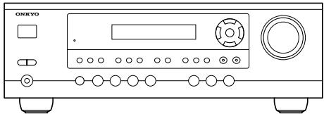
HT-R340
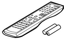
Remote controller & two batteries (AA/R6)
(American type shown)

Indoor FM antenna
(Connector type varies from country to country.)
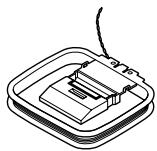
AM loop antenna
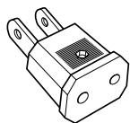
Power-plug adapter
Only supplied in certain countries. Use this adapter if your AC outlet does not match with the plug on the AV receiver's power cord. (Adapter varies from country to country.)
Speaker Package HTP-360 (North American and Asian models)
Front speakers (SKF-360F L/R)
Center speaker (SKC-360C)
Surround speakers (SKM-360S L/R)
Subwoofer (SKW-360)
Speaker Package HTP-318 (European models)
Front speakers (SKF-318F L/R)
Center speaker (SKC-318C)
Surround speakers (SKM-318S L/R)
Subwoofer (SKW-318)
Speaker Package Accessories


Speaker cable for front speakers and center speaker 11 ft. (3.5 m)


Speaker cables for surround speakers 30 ft. (9 m)

Speaker cables for subwoofer 15 ft. (4.5 m)

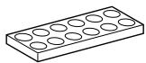
16 thin rubber stoppers, 12 thick rubber stoppers
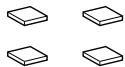
4 floor pads for the subwoofer
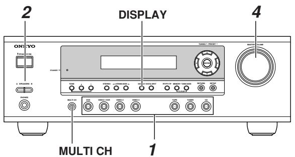
Front Panel
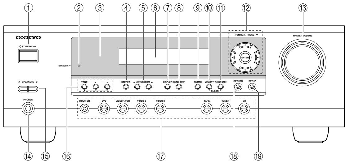
North American and Asian Models
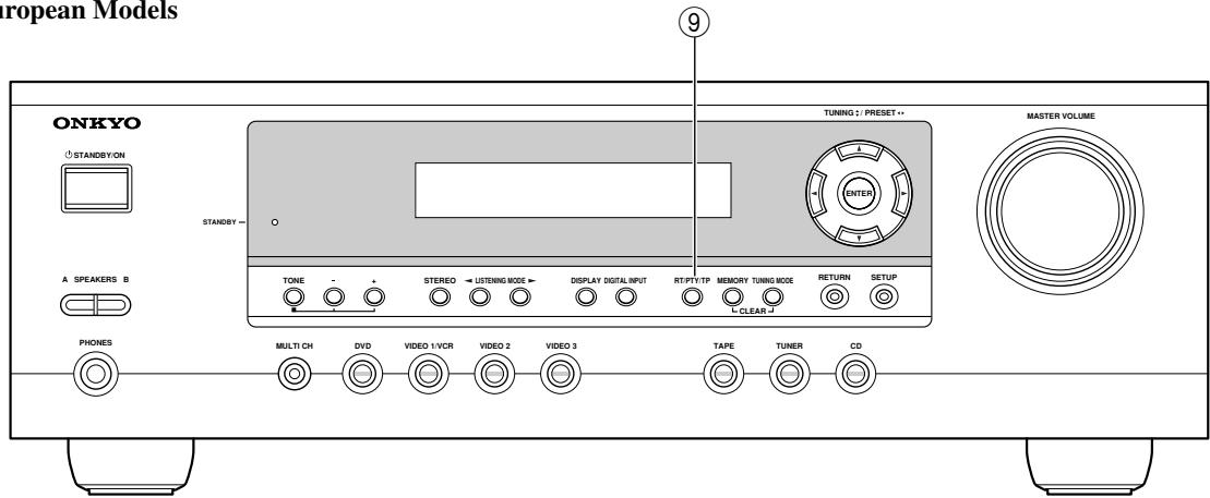
European Models
For detailed information, see the pages in parentheses.
① STANDBY/ON button (37)
This button is used to set the AV receiver to On or Standby.
② STANDBY indicator (37)
This indicator lights up when the AV receiver is in Standby mode, and it flashes while a signal is being received from the remote controller.
③ Remote-control sensor (19)
This sensor receives control signals from the remote controller.
④ STEREO button (49)
This button is used to select the Stereo listening mode.
⑤ LISTENING MODE [<]/[▶] buttons (49)
These buttons are used to select the listening modes.
⑥ Display
See "Display" on page 9.
⑦ DISPLAY button (40)
This button is used to display various information about the currently selected input source.
⑧ DIGITAL INPUT button (38, 57)
This button is used to assign the digital inputs and to specify the format of digital input signals.
DIMMER or RT/PTY/TP button (44, 45)
This button is used to adjust the display brightness. On the European model, this is the RT/PTY/TP button, and it's used with RDS (Radio Data System).
See "Using RDS (European models only)" on page 43.
⑩ MEMORY button (42)
This button is used when storing or deleting radio presets.
⑪ TUNING MODE button (41)
This button is used to select the Auto or Manual tuning mode.
⑫ Arrow/TUNING/PRESET & ENTER buttons (51, 53-56)
When the AM or FM input source is selected, the TUNING [▲] [▼] buttons are used to tune the tuner, and the PRESET [▲] [▶] buttons are used to select radio presets (see pages 41, 42). When the setup menus are used, they work as arrow buttons and are used to select and set items. The ENTER button is also used with the setup menus.
13 MASTER VOLUME control (39)
This control is used to adjust the volume of the AV receiver.
14 PHONES jack (45)
This 1/4-inch phone jack is for connecting a standard pair of stereo headphones for private listening.
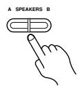
15 SPEAKERS A & B buttons (39)
These buttons are used to turn speaker sets A and B on or off.
16 TONE, [-] & [+] buttons (45)
These buttons are used to adjust the bass and treble.
17 Input selector buttons (38-40)
These buttons are used to select from the following input sources: MULTI CH, DVD,VIDEO 1/VCR,VIDEO 2,VIDEO 3, TAPE, TUNER, or CD.
The [MULTI CH] button selects the DVD analog multichannel input.
RETURN button (51, 53, 54, 56)
This button is used to return to the previously displayed setup menu.
19 SETUP button (51, 53-56)
This button is used to access various settings.
Display
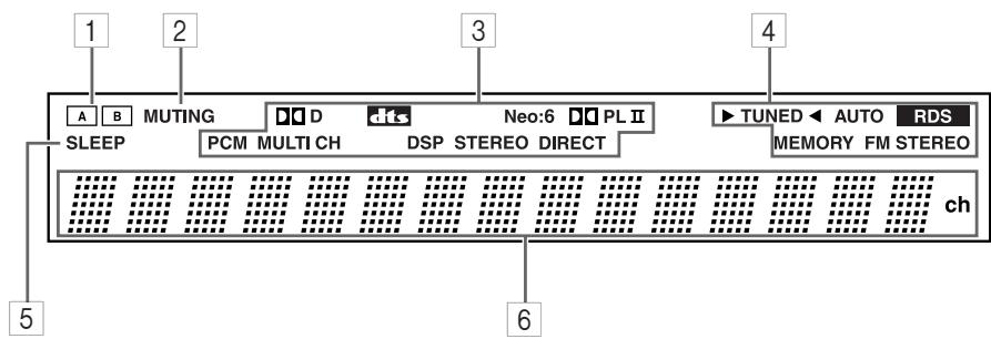
For detailed information, see the pages in parentheses.
1 A & B speaker indicators (20, 39)
Indicator A lights up when speaker set A is on. Indicator B lights up when speaker set B is on.
2 MUTING indicator (46)
This indicator flashes when the AV receiver is muted.
3 Source/listening mode indicators (50, 57)
These indicators show the currently selected listening mode and digital audio format.
4 Tuning indicators
TUNED (41): This indicator lights up when the AV receiver is tuned to a radio station.
AUTO (41): This indicator lights up when Auto
Tuning is selected and disappears when Manual Tuning is selected.
RDS (European model only) (43): This indicator lights up when the AV Receiver is tuned to a radio station that supports RDS (Radio Data System).
MEMORY (42): This indicator lights up when pre-setting radio stations.
FM STEREO (41): This indicator lights up when the AV receiver is tuned to a stereo FM station.
5 SLEEP indicator (46)
This indicator lights up when the Sleep function has been set.
6 Message area
This area of the display shows various information about the currently selected source.
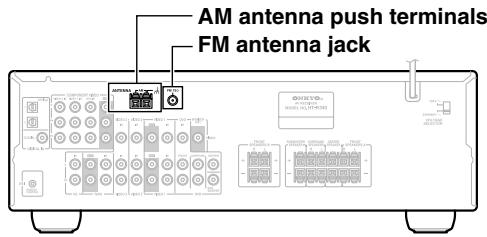
Rear Panel
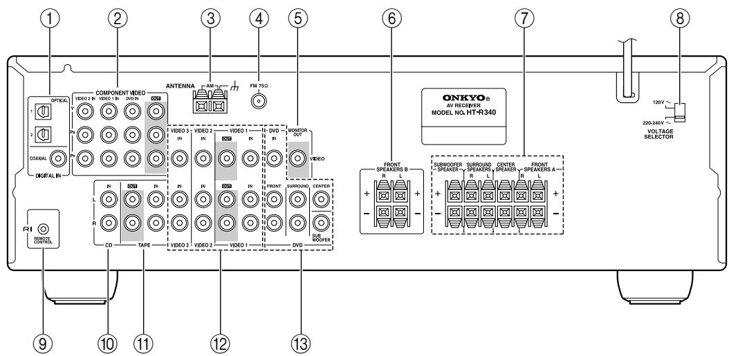
① DIGITAL IN OPTICAL 1, 2 & COAXIAL
These optical and coaxial jacks can be used to connect a CD or DVD player and other components with digital audio outputs.
(2) COMPONENTVIDEO
A DVD player, TV, or other component that supports component video can be connected here.
③ AM ANTENNA
These push terminals are for connecting an AM antenna.
(4) FM ANTENNA
This jack is for connecting an FM antenna.
⑤ MONITOR OUT
The composite video output should be connected to a video input on your TV or projector.
(6) FRONT SPEAKERS B
These push terminals are for connecting speaker set B.
These push terminals are for connecting speaker set A.
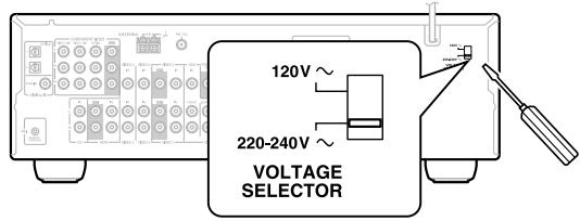
⑧ VOLTAGE SELECTOR (only some models)
This voltage selector provides compatibility with power systems around the world.
⑨ RI
This RI (Remote Interactive) jack can be connected to the RI jack on another Onkyo component. The AV receiver's remote controller can then be used to control that component.
To use RI, you must make an analog audio connection (RCA) between the AV receiver and the other component, even if they are connected digitally.
Note:
RI can only be used with Onkyo components.
10 CD IN
These analog inputs can be used to connect a CD player with analog outputs.
11 TAPE IN/OUT
These analog inputs and outputs can be used to connect a cassette recorder, MiniDisc recorder, or other recorder with analog inputs and outputs.
The VIDEO 1, composite video, and audio inputs and outputs can be used to connect a VCR. The VIDEO 2,VIDEO 3,composite video,and audio inputs can be used to connect another video source (e.g., cable TV, satellite TV, or a set-top box).
13 DVD IN
The FRONT, SURROUND, CENTER, and SUB-WOOFER jacks can be used to connect a component with an analog multichannel audio output, such as a DVD player with a 5.1-channel analog output. The composite video input should be connected to a video output on the DVD player.
See pages 20-36 for connection information.
Front, Center, Surround, & Subwoofer speakers (SKF-360F/SKF-318F, SKC-360C/SKC-318C, SKM-360S/SKM-318S, SKW-360/SKW-318)
Rear
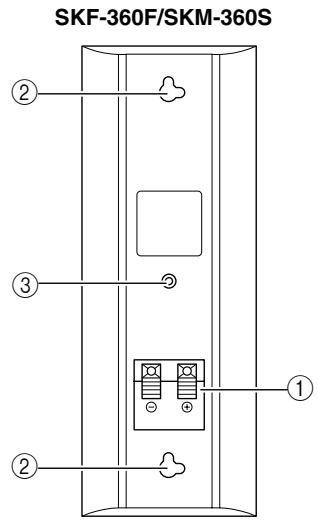
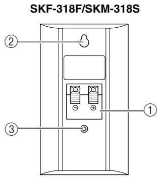
SKW-360/SKW-318
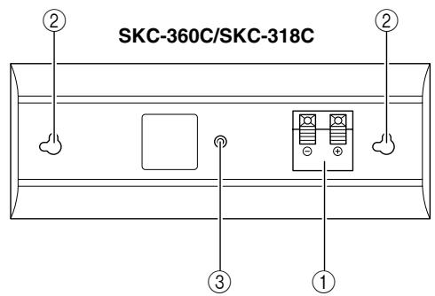
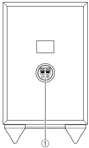
① Speaker terminals
These push terminals are for connecting the speaker to the HT-R340 with the supplied speaker cables.
The supplied speaker cables are color-coded for easy identification. Simply connect each cable to the same-colored positive speaker terminal.
② Keyhole slots
These keyhole slots can be used to wall-mount the speaker. See page 22 for mounting instructions.
③ Speaker mount/bracket inserts
These threaded inserts can be used to attach the speaker to a speaker mount or bracket. See page 22 for mounting instructions.
Note:
Use commercially available machine screws to attach the speaker to a speaker mount or bracket.
North American models require 1/4-inch screws.
Other models require M5 (5 mm) screws.
Caution:
The front grilles are not designed to be removed so do not attempt to remove them forcibly, as this will damage them.
How to Use the Remote Controller
Including the AV receiver, the remote controller can be used to control up to six different components. The remote controller has a specific operating mode for use with each type of component. Modes are selected by using the five REMOTE MODE buttons.
RECEIVER/TAPE Mode
In RECEIVER/TAPE mode, you can control the AV receiver and an Onkyo cassette recorder connected via RI.

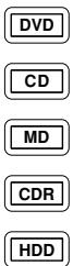
DVD, CD, MD, CDR & HDD Modes
With these modes, you can control an Onkyo DVD player and CD/MD/CDR/HDD player/recorder.
1 Use the REMOTE MODE buttons to select a mode.
2 Use the buttons supported by that mode to control the component.
RECEIVER mode: see right column
DVD mode: see page 14
CD mode: see page 15
MD/CDR mode: see page 16
HDD mode: see page 17
TAPE mode: see page 18
Note:
Some of the remote controller operations described in this manual may not work as expected with other components.
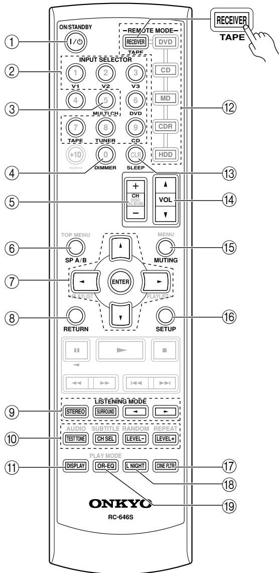
RECEIVER Mode
RECEIVER mode is used to control the AV receiver. To set the remote controller to RECEIVER mode, press the [RECEIVER] REMOTE MODE button.
For detailed information, see the pages in parentheses.
① ON/STANDBY button (37)
This button is used to set the AV receiver to On or Standby.
② INPUT SELECTOR buttons (39)
These buttons are used to select the input sources.
③ MULTI CH button (40)
This button is used to select the multichannel DVD input.
④ DIMMER button (45)
This button is used to adjust the display brightness.
⑤ CH +/- button (42)
This button is used to select radio presets.
⑥ SP A/B button (39)
This button is used to turn speaker sets A and B on or off.
⑦ Arrow [▲]/[▼]/[▲]/[▶] & ENTER buttons (51, 53-56)
These buttons are used to select and adjust settings.
RETURN button (51, 53, 54, 56)
This button is used to return to the previous display when changing settings.
LISTENING MODE buttons (49)
These buttons can be used to select listening modes regardless of the currently selected remote controller mode.
STEREO button
This button selects the Stereo listening mode.
SURROUND button
This button selects the Dolby and DTS listening modes.
[←]/[▶] buttons
These buttons can be used to select any of the available listening modes.
TEST TONE, CH SEL, LEVEL- & LEVEL+ buttons (37, 47, 54)
These buttons are used to adjust the level of each speaker.
⑪ DISPLAY button (40)
This button is used to display various information about the currently selected input source.
⑫ REMOTE MODE buttons (12)
These buttons are used to select the remote controller modes. When you press a button on the remote controller, the REMOTE MODE button for the currently selected mode lights up.
⑬ SLEEP button (46)
This button is used to set the Sleep function.
⑭ VOL [▲]/[▼] button (39)
This button can be used to adjust the volume of the AV receiver regardless of the currently selected remote controller mode.
15 MUTING button (46)
This button is used to mute the AV receiver.
16 SETUP button (51, 53-56)
This button is used to access various settings.
CINE FLTR button (52)
This button is used to set the CinemaFILTER function.
18 L NIGHT button (52)
This button is used to set the Late Night function.
19 OR-EQ button (46)
This button is used to turn on the OptiResponse Equalizer, which optimizes performance when the HT-R340 is used with the speakers included in the HTP-360/HTP-318 Home Theater Speaker Package. When the OptiResponse Equalizer is on, you can enjoy a powerful sound with movies or music even at low volume levels.
DVD Mode
To select your DVD player as the input source, press:

To set the remote controller to DVD mode, press the [DVD] REMOTE MODE button.
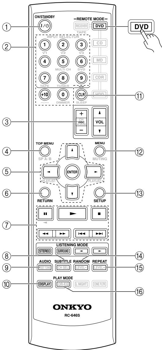
① ON/STANDBY button
This button sets the DVD player to On or Standby.
② Number buttons
These buttons are used to enter title, chapter, and track numbers and to enter times for locating specific points in time.
③ DISC +/- button
This button selects discs on a DVD changer.
(4) TOP MENU button
This button is used to select a DVD's top menu.
⑤ Arrow [▲]/[▼]/[▲]/[▶] & ENTER buttons
These buttons are used to navigate DVD menus and the DVD player's onscreen setup menus.
⑥ RETURN button
This button is used to exit the DVD player's onscreen setup menu and to restart menu playback.
⑦ Playback buttons
From left to right: Pause, Play, Stop, Fast Reverse, Fast Forward, Previous, and Next.
SUBTITLE button
This button is used to select subtitles.
⑨ AUDIO button
This button selects foreign language soundtracks and audio formats (e.g., Dolby Digital or DTS).
10 DISPLAY button
This button is used to display information about the current disc, title, chapter, or track on the DVD player's display, including the elapsed time, remaining time, total time, and so on.
⑪ CLR button
This button is used to cancel functions and to clear entered numbers.
12 MENU button
This button is used to display a DVD's menu.
13 SETUP button
This button is used to access the DVD player's onscreen setup menus.
14 RANDOM button
This button is used with the random playback function.
15 REPEAT button
This button is used to set the repeat playback functions.
16 PLAY MODE button
This button is used to select play modes on a component with selectable play modes.
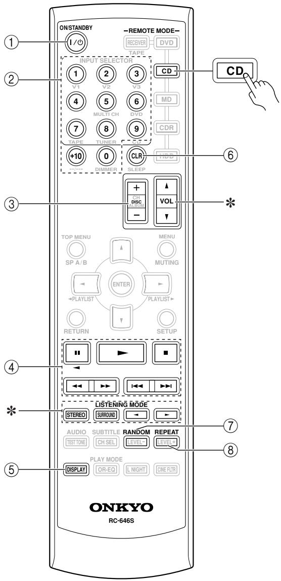
CD Mode
To select your CD player as the input source, press:
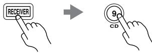
To set the remote controller to CD mode, press the [CD] REMOTE MODE button.
① ON/STANDBY button
This button sets the CD player to On or Standby.
② Number buttons
These buttons are used to enter track numbers and to enter times for locating specific points in time.
③ DISC +/- button
This button selects discs on a CD changer.
④ Playback buttons
From left to right: Pause, Play, Stop, Fast Reverse, Fast Forward, Previous and Next.
⑤ DISPLAY button
This button is used to display information about the current disc or track on the CD player's display, including the elapsed time, remaining time, total time, and so on.
⑥ CLR button
This button is used to cancel functions and to clear entered numbers.
⑦ RANDOM button
This button is used with the random playback function.
⑧ REPEAT button
This button is used to set the repeat playback functions.
* The VOL [ ] / [ ] and LISTENING MODE buttons work the same as for RECEIVER mode.
MD, & CDR Mode
To select your MiniDisc or CD recorder as the input source, press:
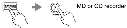
- You must change the Input Display (see page 38).
To set the remote controller to MD or CDR mode, press the [MD] or [CDR] REMOTE MODE button.
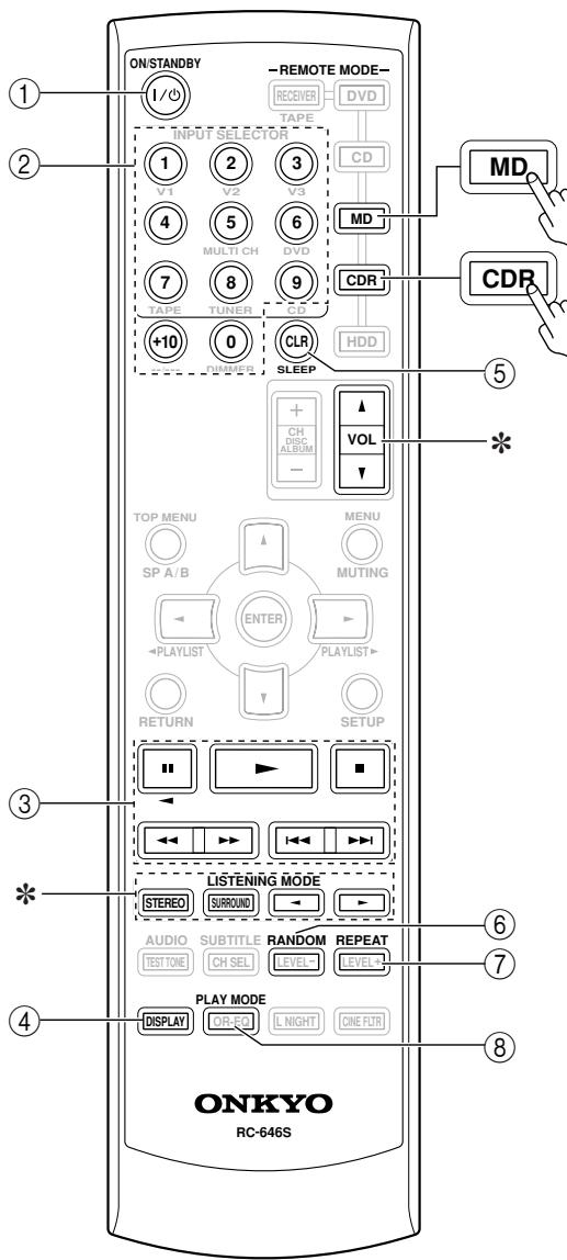
① ON/STANDBY button
This button sets the MD/CD recorder to On or Standby.
② Number buttons
These buttons are used to enter track numbers and to enter times for locating specific points in time. The [+10] button is used to enter numbers above 10.
③ Playback buttons
From left to right: Pause, Play, Stop, Fast Reverse, Fast Forward, Previous and Next.
④ DISPLAY button
This button is used to display information about the current disc or track on the MD/CD recorder's display, including the elapsed time, remaining time, total time, and so on.
⑤ CLR button
This button is used to cancel functions and to clear entered numbers.
⑥ RANDOM button
This button is used with the random playback function.
⑦ REPEAT button
This button is used to set the repeat playback functions.
⑧ PLAY MODE button
This button is used to select play modes on a component with selectable play modes.
* The VOL [ ] / [ ] and LISTENING MODE buttons work the same as for RECEIVER mode.
HDD Mode
HDD mode is for controlling an Apple iPod in an Onkyo RI Dock that's connected via RI.
To select an Onkyo RI Dock that's connected via RI as the input source, press:
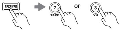
* You must change the Input Display (see page 38).
See page 34 for more information.
To set the remote controller to HDD mode, press the [HDD] REMOTE MODE button.
① ON/STANDBY button
This button sets the iPod to On or Standby.
② ALBUM +/- button
This button selects the next or previous album on an iPod.
③ PLAYLIST[ll][1]buttons
These buttons select the previous or next playlist on the iPod.
④ Playback buttons
From left to right: Pause, Play, Stop, Fast Reverse, Fast Forward, Previous and Next.
⑤ DISPLAY button
This button turns on the iPod's display for 30 seconds.
⑥ MENU, ENTER, and Up and Down [▲]/[▼] buttons
MENUBuTion: Displays the iPod's menu.
[] / [] buttons: Select options on the iPod's menu.
ENTER button: Confirms the selection on the iPod's menu.
⑦ RANDOM button
This button is used with the random playback function.
⑧ REPEAT button
This button is used to set the repeat playback functions.
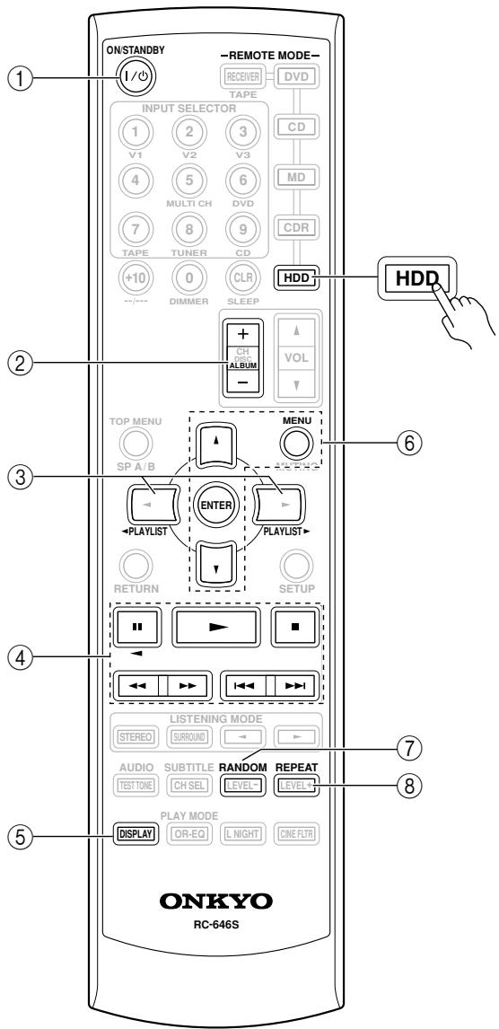
TAPE Mode
To select your Cassette deck as the input source, press:

TAPE mode is used to control an Onkyo cassette recorder connected to the AV receiver via RI.
To set the remote controller to TAPE mode, press the [RECEIVER] REMOTE MODE button.
For twin cassette decks, only deck B can be controlled.
① Play [▶] button
This button is used to start playback.
② Stop [■] button
This button is used to stop playback.
③ Reverse Play [<] button
This button is used to start reverse playback.
④ Rewind & FF [←] [/→] buttons
The Rewind [] button is used to start rewind. The FF [ ] button is used to start fast forward.
Setting the Voltage Selector (on some models)
Some models have a voltage selector switch for compatibility with power systems around the world. Before you plug in this model, make sure that the voltage selector is set to the correct voltage for your area. If it isn't, use a small screwdriver to set it as appropriate. For example, if the voltage in your area is 120 volts, set the selector to "120V." If it's between 220 and 240 volts, set it to "220-240V."
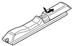
Installing the Batteries
1 To open the battery compartment, press the small hollow and slide open the cover.
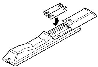
2 Insert the two supplied batteries (AA/R6) in accordance with the polarity diagram inside the battery compartment.
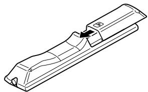
3 Slide the cover shut.
Notes:
- If the remote controller doesn't work reliably, try replacing the batteries.
- Don't mix new and old batteries or different types of batteries.
- If you intend not to use the remote controller for a long time, remove the batteries to prevent damage from leakage or corrosion.
- Expired batteries should be removed as soon as possible to prevent damage from leakage or corrosion.
Using the Remote Controller
To use the remote controller, point it at the AV receiver's remote control sensor, as shown below.
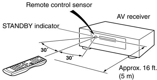
Notes:
- The remote controller may not work reliably if the AV receiver is subjected to bright light, such as direct sunlight or inverter-type fluorescent lights. Keep this in mind when installing.
- If another remote controller of the same type is used in the same room, or the AV receiver is installed close to equipment that uses infrared rays, the remote controller may not work reliably.
- Don't put anything, such as a book, on the remote controller, because the buttons may be pressed inadvertently, thereby draining the batteries.
- The remote controller may not work reliably if the AV receiver is installed in a rack behind colored glass doors. Keep this in mind when installing.
- The remote controller will not work if there's an obstacle between it and the AV receiver's remote control sensor.
Speaker Sets A and B
You can use two sets of speakers with the AV receiver: speaker set A and speaker set B .
Speaker set A should be used in your main listening room for up to 5.1-channel playback.
*While speaker set B is on, speaker set A is reduced to 2.1-channel playback.
Speaker set B can be used in another room and offers 2-channel stereo playback.
AV receiver
or

Remote
controller
| Speaker set A | Speaker set B | Indicator | Output |
| On | On | A B | Set A: 2.1 channels Set B: 2 channels |
| Off | A | Set A: 5.1 channels | |
| Off | On | B | Set B: 2 channels |
| Off | No sound |
Speaker Set A: Main Room
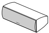
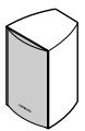
Center speaker (SKC-360C)
This speaker enhances the front left and right speakers, making sound movements distinct and providing a full sound image. For movies it's used mainly for dialog.
Position it close to your TV facing forward at about ear level, or at the same height as the front left and right speakers.
- While speaker set B is on, this speaker outputs no sound.
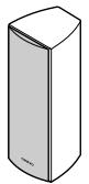
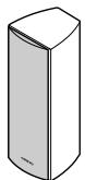
Front left and right speakers (SKF-360F L/R)
These output the overall sound. Their role in a home theater is to provide a solid anchor for the sound image. They should be positioned facing the listener at about ear level, and equally spaced from the TV. Angle them inward.
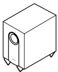
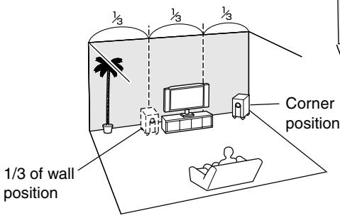
Subwoofer (SKW-360)
The subwoofer handles the bass sounds of the LFE (Low-Frequency Effects) channel. In general, a good bass sound can be obtained by installing the subwoofer in a front corner, or at one-third the way along the wall, as shown.
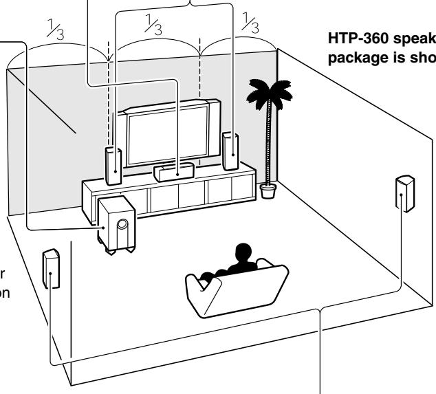
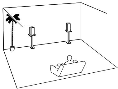
Speaker Set B: Sub Room
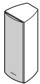
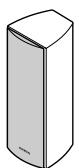
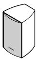
Surround left and right speakers (SKM-360S L/R)
These speakers are used for precise sound positioning and to add realistic ambience. Position them at the sides of the listener, or slightly behind, about 2-3 feet (60-100 cm) above ear level. Ideally they should be equally spaced from the listener.
- While speaker set B is on, these speakers output no sound.
Speaker Connection Precautions
Read the following before connecting your speakers:
- You can connect speakers with an impedance of 6 ohms or higher. If you use speakers with a lower impedance, and use the amplifier at high volume levels for a long period of time, the built-in protection circuit may be activated.
- Disconnect the power cord from the wall outlet before making any connections.
- Pay close attention to speaker wiring polarity. In other words, connect positive (+) terminals to only positive (+) terminals, and negative (-) terminals to only negative (-) terminals. If you get them the wrong way around, the sound will be out of phase and will sound unnatural.
- Unnecessarily long, or very thin speaker cables may affect the sound quality and should be avoided.
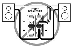
- Be careful not to short the positive and negative wires. Doing so may damage the AV receiver.
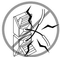
- Don't connect more than one cable to each speaker terminal. Doing so may damage the AV receiver.
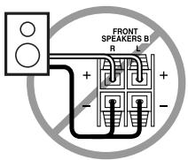
- Don't connect one speaker to several terminals.
Connecting Speaker
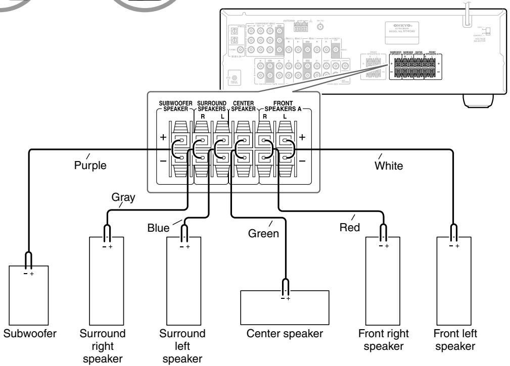
The AV receiver's positive (+) speaker terminals are color-coded for ease of identification. (The negative (-) speaker terminals are all black.)
| Speaker terminal | Color |
| Front left | White |
| Front right | Red |
| Center | Green |
| Surround left | Blue |
| Surround right | Gray |
| Subwoofer | Purple |
1 Strip 3 / 8" (10 mm) of insulation from the ends of the speaker cables. (Supplied speaker cables are already stripped.)
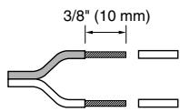
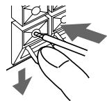
2 While pressing the lever, insert the wire into the hole, and then release the lever. Make sure that the terminals are gripping the bare wires, not the insulation.
The following illustration shows which speaker should be connected to each pair of terminals.
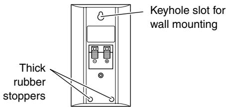
Wall Mounting
The speakers can easily be wall mounted by using the keyhole slots. To prevent the speaker from vibrating against the wall, attach two of the supplied thick rubber stoppers to the rear of each speaker.
To mount the front or surround speakers vertically, use the keyhole slot shown to hang each speaker on a screw that's securely screwed into the wall.
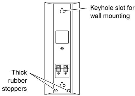
HTP-360 Front/Surround speakers (SKF-360F/SKM-360S)
HTP-318 Front/Surround speakers (SKF-318F/SKM-318S)
To mount the center speaker horizontally, use the two keyhole slots shown to hang each speaker on two screws that are securely screwed into the wall.

Center speaker (SKC-360C/SKC-318C)
Caution:
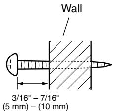
A mounting screw's ability to support a speaker depends on how well it's anchored to the wall. If you have hollow walls, screw each mounting screw into a stud. If there are no studs, or the walls are solid, use suitable wall anchors.
Use screws with a head diameter of 5 / 16'' (9 mm) or less and a shank diameter of 1 / 8'' (4 mm) or less. With hollow walls, use a cable/pipe detector to check for any power cables or water pipes before making any holes.
Leave a gap of between 3 / 16'' (5 mm) and 7 / 16'' (10 mm) between the wall and the base of the screw head, as shown. (We recommend that you consult a home installation professional.)
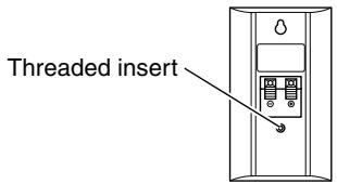
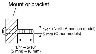
Using Speaker Mounts/Brackets
Threaded inserts for machine screws are provided on the rear of each speaker for wall-mounting with commercially available speaker mounts or brackets. North American models require 1/4-inch screws. Other models require M5 (5 mm) screws. Refer to the manual supplied with your mounts or brackets for installation details.
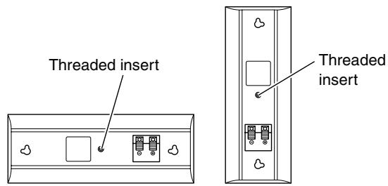
Note:
- The portion of the screw that goes into the speaker's threaded insert should be between 1/4'' - 5/16'' (5 mm - 8 mm) long.
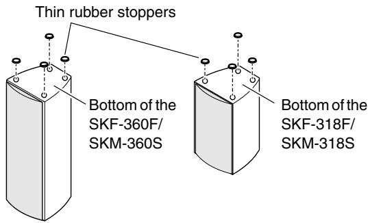
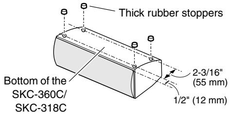
Using the Rubber Stoppers for a More Stable Platform
We recommend using the provided rubber stoppers to achieve the best possible sound from your speakers. The rubber stoppers prevent the speakers from moving, providing a more stable platform. Use thick stoppers for the center speaker, and thin stoppers for the other speakers.
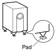
Using the Floor Pads for Subwoofer
If the subwoofer is placed on a hard floor (wood, vinyl, tile, etc.) and playback is very loud, the subwoofer's feet may damage the flooring. To prevent this, place the supplied pads underneath the subwoofer's feet. The pads also provide a stable base for the subwoofer.
This section explains how to connect the supplied indoor FM antenna and AM loop antenna, and how to connect commercially available outdoor FM and AM antennas. The AV receiver won't pick up any radio signals without any antenna connected, so you must connect the antenna to use the tuner.
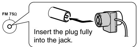
Connecting the Indoor FM Antenna
The supplied indoor FM antenna is for indoor use only.
1 Attach the FM antenna, as shown.
American Model
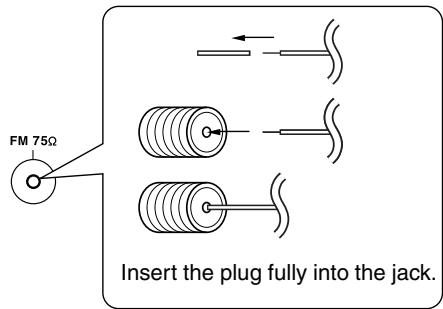
Other Models
Once your AV receiver is ready for use, you'll need to tune into an FM radio station and adjust the position of the FM antenna to achieve the best possible reception.
2 Fully extend the antenna and point it in various directions to find the best reception. Secure it in that position with thumb-tacks or something similar.
If you cannot achieve good reception with the supplied indoor FM antenna, try a commercially available outdoor FM antenna instead (see page 25).
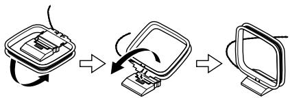
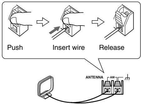
Connecting the AM Loop Antenna
The supplied indoor AM loop antenna is for indoor use only.
1 Assemble the AM loop antenna, inserting the tabs into the base, as shown.
2 Connect both wires of the AM loop antenna to the AM push terminals, as shown.
(The antenna's wires are not polarity sensitive, so they can be connected either way around).
Make sure that the wires are attached securely and that the push terminals are gripping the bare wires, not the insulation.
Once your AV receiver is ready for use, you'll need to tune into an AM radio station and adjust the position of the AM antenna to achieve the best possible reception.
Keep the antenna as far away as possible from your AV receiver, TV, speaker cables, and power cords.
If you cannot achieve good reception with the supplied indoor AM loop antenna, try using it with a commercially available outdoor AM antenna (see page 25).
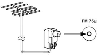
Connecting an Outdoor FM Antenna
If you cannot achieve good reception with the supplied indoor FM antenna, try a commercially available outdoor FM antenna instead.
Notes:
- Outdoor FM antennas work best outside, but usable results can sometimes be obtained when installed in an attic or loft.
- For best results, install the outdoor FM antenna well away from tall buildings, preferably with a clear line of sight to your local FM transmitter.
- Outdoor antenna should be located away from possible noise sources, such as neon signs, busy roads, etc.
- For safety reasons, outdoor antenna should be situated well away from power lines and other high-voltage equipment.
- Outdoor antenna must be grounded in accordance with local regulations to prevent electrical shock hazards.
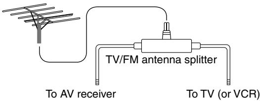
Using a TV/FM Antenna Splitter
It's best not to use the same antenna for both FM and TV reception, as this can cause interference problems. If circumstances demand it, use a TV/FM antenna splitter, as shown.
Connecting an Outdoor AM Antenna
If good reception cannot be achieved using the supplied AM loop antenna, an outdoor AM antenna can be used in addition to the loop antenna, as shown.
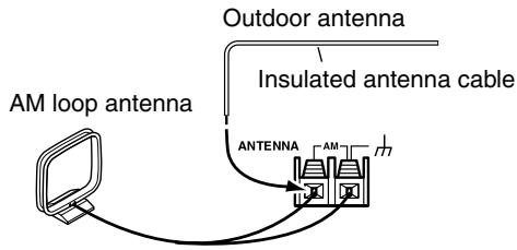
Outdoor AM antennas work best when installed outside horizontally, but good results can sometimes be obtained indoors by mounting horizontally above a window. Note that the AM loop antenna should be left connected.
Outdoor antenna must be grounded in accordance with local regulations to prevent electrical shock hazards.
About AV Connections
- Before making any AV connections, read the manuals supplied with your other AV components.
- Don't connect the power cord until you've completed and double-checked all AV connections.
Optical Digital Jacks
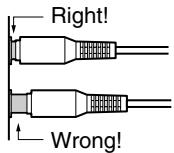
The AV receiver's optical digital jack has shutter-type cover that open when an optical plug is inserted and close when it's removed. Push plugs in all the way.
Caution: To prevent shutter damage, hold the optical plug straight when inserting and removing.
AV Connection Color Coding
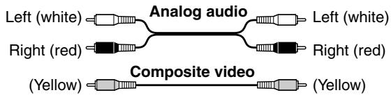
RCA-type AV connections are usually color coded: red, white, and yellow. Use red plugs to connect right-channel audio inputs and outputs (typically labeled "R"). Use white plugs to connect left-channel audio inputs and outputs (typically labeled "L"). And use yellow plugs to connect composite video inputs and outputs.
- Push plugs in all the way to make good connections (loose connections can cause noise or malfunctions).
- To prevent interference, keep audio and video cables away from power cords and speaker cables.
AV Cables & Jacks
Video
| Cable | Jack | Description | |
| Component video cable | YPBPRPBRP | YPBPRP | Component video separates the luminance (Y) and color difference signals (PR, PB), providing the best picture quality. (Some TV manufacturers label their component video jacks slightly differently.) |
| Composite video cable | VIDEO | VIDEO | Composite video is commonly used on TVs, VCRs, and other video equipment. Use only dedicated composite video cables. |
Audio
| Cable | Jack | Description | |
| Optical digital audio cable | OPTICAL | Offers the best sound quality and allows you to enjoy surround sound (e.g., Dolby Digital, DTS). The audio quality is the same as for coaxial. | |
| Coaxial digital audio cable | COAXIAL | Offers the best sound quality and allows you to enjoy surround sound (e.g., Dolby Digital, DTS). The audio quality is the same as for optical. | |
| Analog audio cable (RCA) | L R | This cable carries analog audio. It's the most common connection format for analog audio and can be found on virtually all AV components. | |
| Multichannel analog audio cable (RCA) | FRONT SURROUND CENTER DVD SUBwoofer | This cable carries multichannel analog audio and is typically used to connect DVD players with a 5.1-channel analog audio output. Several standard analog audio cables can be used instead of a multichannel cable. | |
Note: The AV receiver does not support SCART plugs.
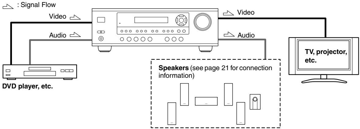
Connecting Both Audio & Video
By connecting both the audio and video outputs of your DVD player and other AV components to the AV receiver, you can select both the audio and video simultaneously simply by selecting the appropriate input source on the AV receiver.
Which Connections Should I Use?
The AV receiver supports several connection formats for compatibility with a wide range of AV equipment. The format you choose will depend on the formats supported by your other components. Use the following sections as a guide. For video components, such as a DVD player, you must make two connections—one for audio, one for video.
Video Connection Formats
Video equipment can be connected to the AV receiver using one of the following video connection formats: composite video, or component video, the latter offering the best picture quality.
When choosing a connection format, bear in mind that the AV receiver doesn't convert between formats, so only outputs of the same format as the input will output the signal.
For example, if you connect your DVD player to the COMPONENT VIDEO DVD IN, a video signal will be output by the COMPONENT OUT, but not by any composite video outputs.
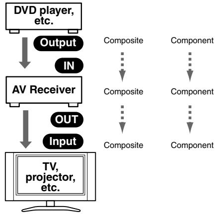
Video Input/Output Diagram
Audio Connection Formats
Audio equipment can be connected to the AV receiver using the following audio connection formats: analog, optical, coaxial, and multichannel.
When choosing a connection format, bear in mind that the AV receiver doesn't convert between formats.
For example, audio signals connected to an OPTICAL or COAXIAL digital input are not output by the analog TAPE OUT, so if you want to record from, for example, your CD player, in addition to connecting it to a digital input, you must also connect it to the analog CD IN.
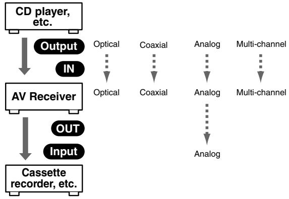
Audio Input/Output Diagram for Recording
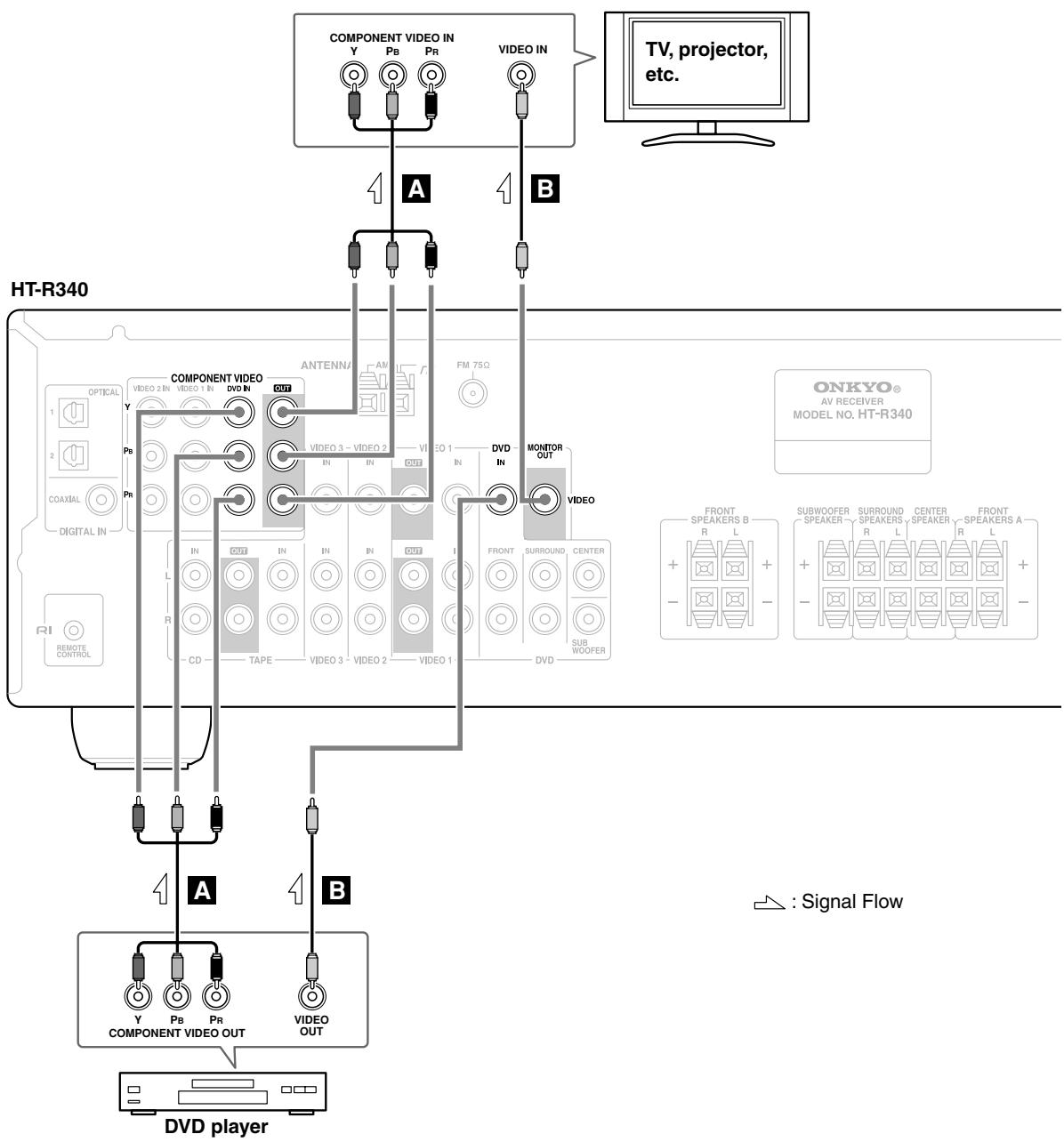
Connecting a DVD Player
Step 1: Video Connection (DVD Player to AV Receiver to TV)
A If your TV has component video input jacks, connect your DVD player to the AV receiver's COMPONENT VIDEO DVD IN jacks. And connect the AV receiver's COMPONENT VIDEO OUT jacks to your TV. This will provide better picture quality than connection B.
If your TV doesn't have component video input jacks, connect your DVD player to the AV receiver's DVD IN VIDEO jack. And connect the AV receiver's MONITOR OUT VIDEO jack to your TV.
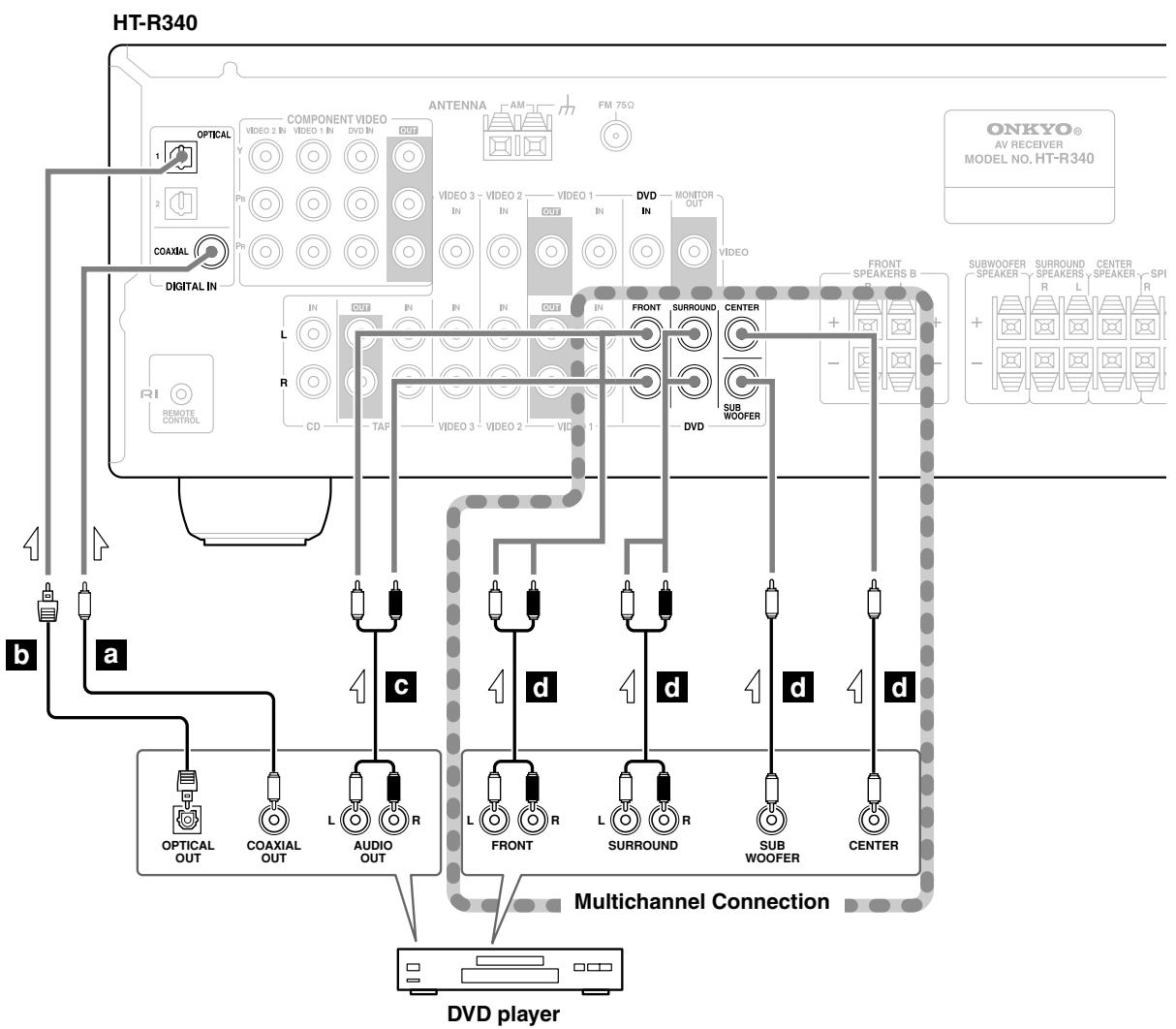
Step 2: Audio Connection
a If your DVD player has a coaxial digital audio output jack, connect it to the AV receiver's DIGITAL IN COAX-IAL jack. You can enjoy Dolby and DTS listening modes with this connection.
b If your DVD player has an optical digital audio output jack instead of coaxial one, connect it to the AV receiver's DIGITAL IN OPTICAL 1 or 2 jack, and set the DIGITAL INPUT assignment to OPT1 or OPT 2 (see page 38). Coaxial connections perform the same as optical ones.
c Optionally, connecting your DVD player's audio out L/R jacks to the AV receiver's DVD IN FRONT L/R jacks will allow you to record audio from your DVD player.
Note: If your DVD player has main L/R output jacks and multichannel L/R output jacks, use the main L/R output jacks.
—Multichannel Audio Connection—
d If your DVD player has analog multichannel output jacks, connect them to the AV receiver's DVD IN FRONT, SURROUND, CENTER, and SUBWOOFER jacks. Use a multichannel analog cable or several normal audio cables. You can enjoy DVD-Audio or SACD with this connection.
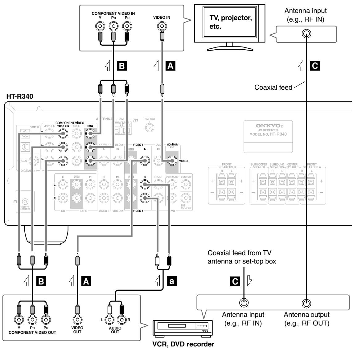
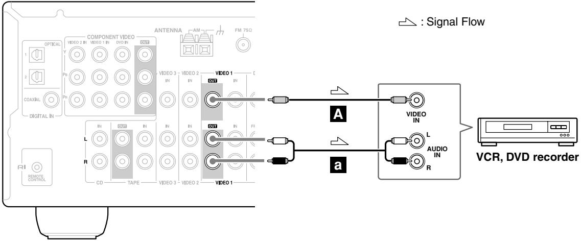
Connecting a VCR
Connecting a VCR for Playback
Step 1: Video Connection (VCR to AV Receiver to TV)
A Connect your VCR's video output jack to the AV receiver's VIDEO 1 IN jack and connect the AV receiver's MONITOR OUT jack to your TV's video input jack.
If your VCR and TV have component video jacks, connect the VCR's component video output jacks to the AV receiver's COMPONENT VIDEO 1 IN jacks, and connect the AV receiver's COMPONENT VIDEO OUT jacks to your TV's component video in jacks. This offers better picture quality than composite video.
Connect a TV antenna output jack (e.g., RF OUT) to your VCR's antenna input, and connect your VCR's antenna output jack to your TV's antenna input jack.
Step 2: Audio Connection
a Connect your VCR's audio output jacks to the AV receiver's VIDEO 1 IN L/R jacks.
Connecting a VCR for Recording
Step 1: Video Connection
A Connect the AV receiver's VIDEO 1 OUT jack to your VCR's video input jack.
Step 2: Audio Connection
a Connect the AV receiver's VIDEO 1 OUT L/R jacks to your VCR's audio input jacks.
HT-R340
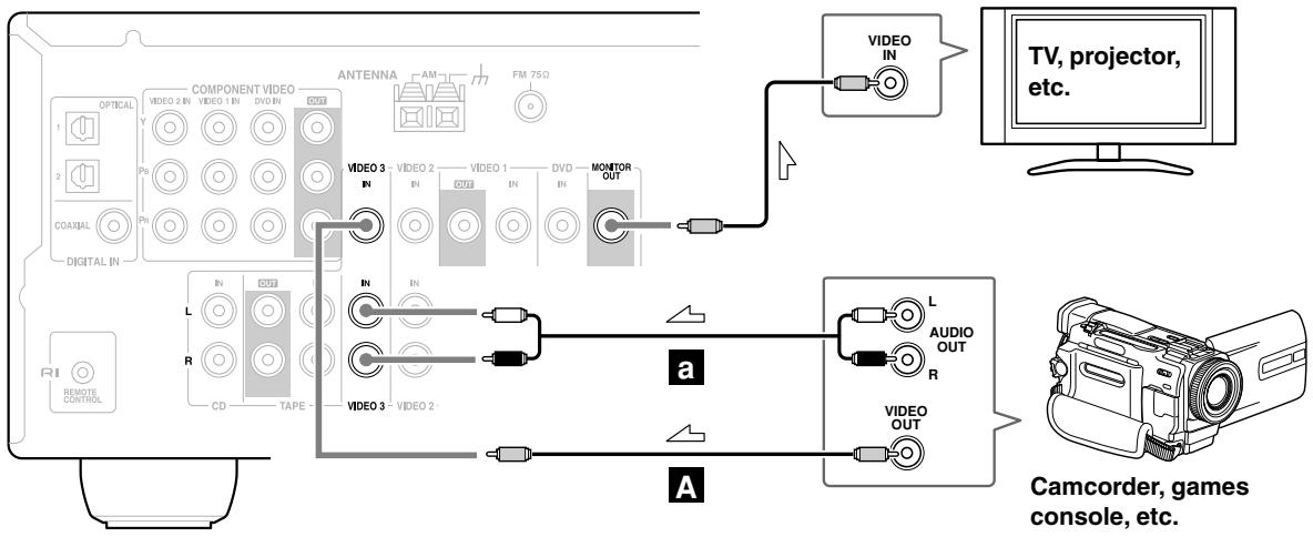
Connecting a Camcorder, Games Console, or Other Device
Step 1: Video Connection
A Connect your camcorder's video output jack to the AV receiver's VIDEO 3 IN jack.
Step 2: Audio Connection
a Connect your camcorder's audio output jack to the AV receiver's VIDEO 3 IN L/R jacks.
HT-R340
:Signal Flow
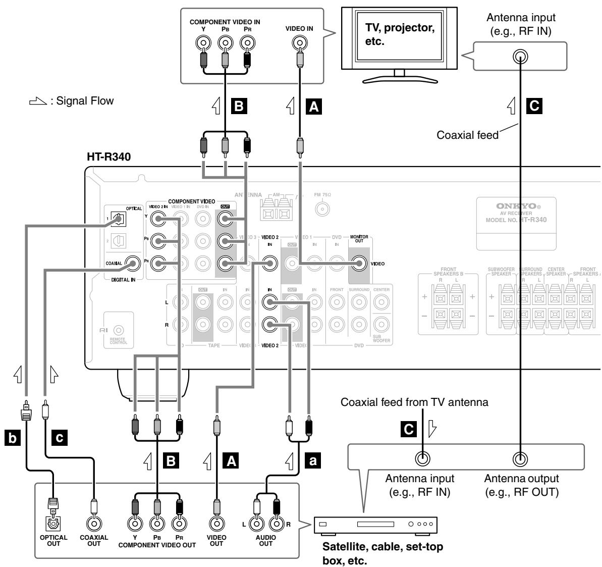
Connecting a Satellite, Cable, Set-top Box, or Other Video Source
Step 1: Video Connection
A Connect your set-top box's video output jack to the AV receiver's VIDEO 2 IN jack and connect the AV receiver's MONITOR OUT jack to your TV's video input jack.
If your VCR and TV have component video jacks, connect your set-top box's component video output to the AV receiver's COMPONENT VIDEO Video 2 IN jacks, and connect the AV receiver's COMPONENT VIDEO OUT jacks to your TV's component video in jacks. This offers better picture quality than composite video.
Connect a coaxial feed from a TV antenna to your set-top box's antenna input jack (e.g., RF IN), and connect your set-top box's antenna output jack (e.g., RF OUT) to your TV's antenna input jack.
Step 2: Audio Connection
a Connect your set-top box's audio output jack to the AV receiver's VIDEO 2 IN L/R jacks.
b If your set-top box has an optical digital audio output jack, connect it to the AV receiver's DIGITAL IN OPTICAL 1 jack. You can enjoy Dolby and DTS listening modes with this connection.
c If your set-top box has a coaxial digital audio output jack instead of an optical one, connect it to the AV receiver's DIGITAL IN COAXIAL jack, and set the DIGITAL INPUT assignment to COAX (see page 38). Coaxial connections perform the same as optical ones.
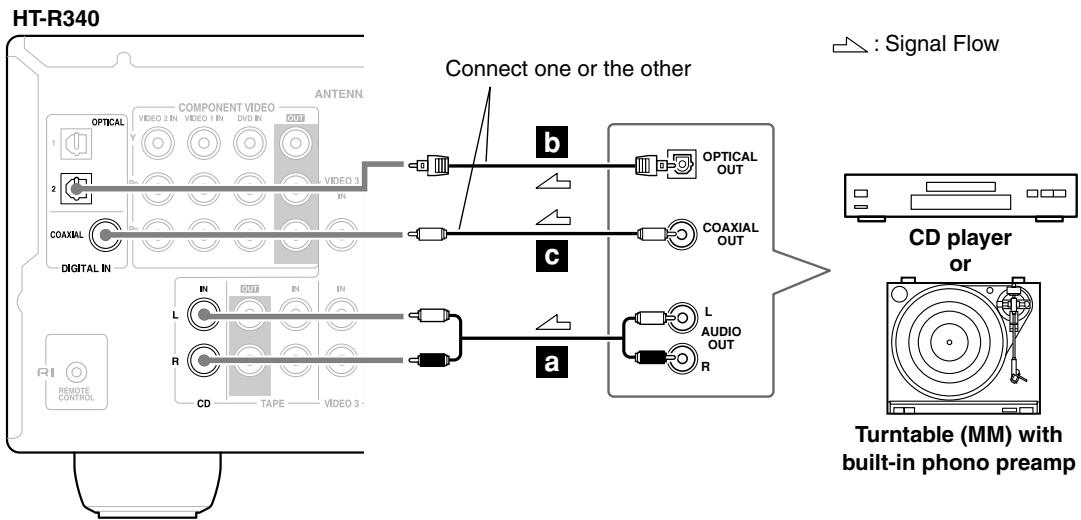
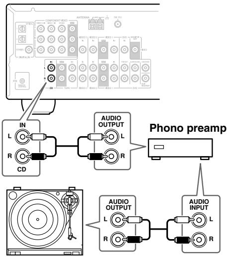
Connecting a CD Player or Turntable
CD Player or Turntable with Built-in Phono Preamp
a Connect your CD player's analog audio output jacks, or your turntable with built-in phono preamp's audio output jacks to the AV receiver's CD IN L/R jacks. With connection a, you can listen to and record audio from the CD player or turntable.
b If your CD player has an optical output jack, connect it to the AV receivers DIGITAL IN OPTICAL 2 jack.
c If your CD player has a coaxial output jack instead of an optical one, connect it to the AV receiver's DIGITAL IN COAXIAL jack, and set the DIGITAL INPUT assignment to COAX (see page 38). Coaxial connections perform the same as optical ones.
Turntable (MM) with no Phono Preamp Built-in
A phono preamp is necessary to connect a turntable that doesn't have a phono preamp built-in.
HT-R340
Turntable with an MC (Moving Coil) Cartridge
An MC head amp and phono preamp are necessary to connect a turntable with an MC (Moving Coil) cartridge.
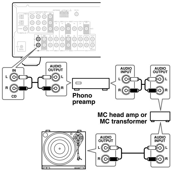
HT-R340
Connecting an Onkyo RI Dock for the iPod
Not all iPods output video.
For information about which iPod models are supported by the RI Dock, see the RI Dock's instruction manual.
If Your iPod Supports Video:
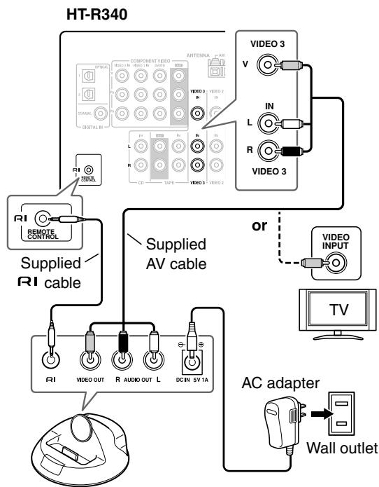
If Your iPod Doesn't Support Video:
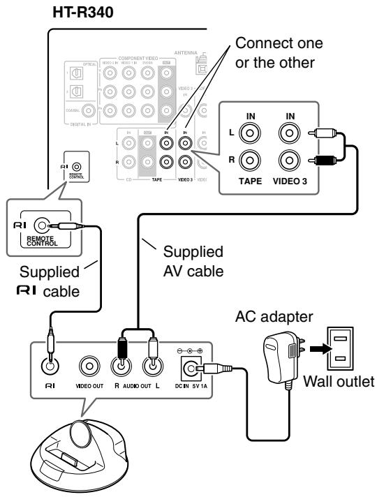
- If you connect the RI Dock's AUDIO OUT L/R jacks to the AV receiver's TAPE IN jacks and also want to connect the RI Dock's VIDEO OUT jack to the AV receiver:
Connect the RI Dock's VIDEO OUT jack to an unused video input on the AV receiver. Do not connect it to the COMPONENT VIDEO jackets. To watch an iPod slideshow or video, select the video input source first, and then select the TAPE input source. The AV receiver will output the audio being fed to the TAPE input, and because the video source doesn't change when the TAPE input source is selected, it'll continue to output the video being fed to the video input. - What to do if you already have a component connected to the AV receiver's VIDEO 3 IN or TAPE IN jacks:
You can connect the RI Dock to an unused AV input on the AV receiver, however, you will not be able to control your iPod with the AV receiver's remote controller, as the RI functionality will be unavailable. The VIDE 3 IN and TAPE IN jacks are especially designed for use with the RI Dock.
Notes:
- If you have an Onkyo DS-A1 RI Dock, connect its S-VIDEO jack directly to an S-Video input on your TV.
- Set the RI Dock's RI MODE switch to HDD or HDD/DOCK.
- Set the AV receiver's Input Display to HDD (see page 38).
- See the RI Dock's instruction manual for more information.
- When the AC adapter is unplugged or not connected to the RI Dock, the RI Dock will output no sound or video, RI functions will not work, and your iPod's battery will not be charged.
- Connect the supplied RI cable to only RI jacks. Do not connect headphones to the RI jack, as it will damage your equipment.
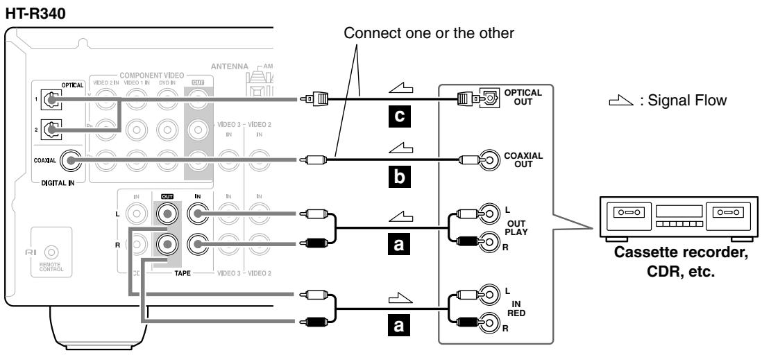
Connecting a Cassette, CDR, MiniDisc, or DAT Recorder
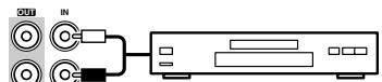
a Connect your recorder's audio input jacks to the AV receiver's TAPE OUT L/R jacks, and connect your recorder's audio output jacks to the AV receiver's TAPE IN L/R jacks. With connection a, you can play and record with the recorder.
b If your recorder has a coaxial digital output jack, connect it to the AV receiver's DIGITAL IN COAXIAL jack, and set the DIGITAL INPUT assignment to COAX (see page 38).
c If your recorder has an optical output jack instead of a coaxial one, connect it to the AV receiver's DIGITAL IN OPTICAL 1 or 2 jack and set the DIGITAL INPUT assignment to OPT1 or OPT2 (see page 38).
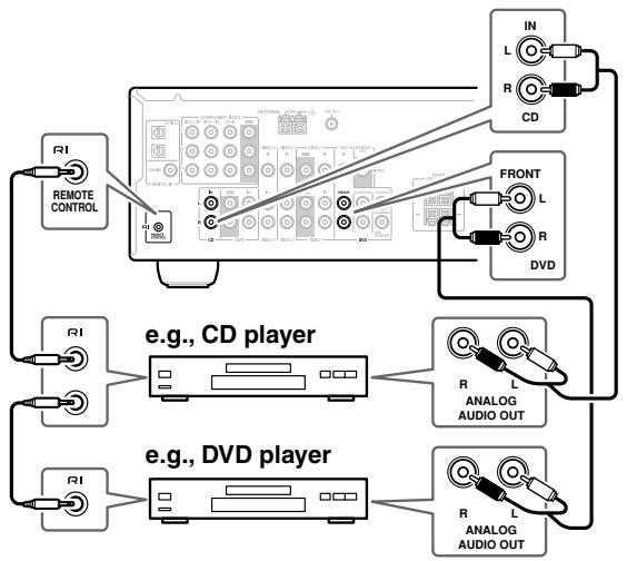
Connecting Onkyo R1 Components
Step 1: Make sure that each Onkyo component is connected to the AV receiver with an analog audio cable.
Step 2: Make the RI connection.
Step 3: If you're using an MD, CDR, or HDD component, change the Input Display (see page 38).
With RI (Remote Interactive), you can use the following special functions:
Auto Power On/Standby
When you start playback on a component connected via RI, if the AV receiver is on Standby, it will automatically turn on and select that component as the input source. Similarly, when the AV receiver is set to Standby, all components connected via RI will also go on Standby.
Direct Change
When playback is started on a component connected via RI, the AV receiver automatically selects that component as the input source. If your DVD player is connected to the AV receiver's multichannel DVD input, you'll need to press the [MULTI CH] button to hear all channels (see page 40), as the Direct Change RI function only selects the FRONT DVD IN jacks.
Remote Control
You can use the AV receiver's remote controller to control your other RI-capable Onkyo components, pointing the remote controller at the AV receiver's remote control sensor instead of the component.
Notes:
- Use only RI cables for RI connections. RI cables are supplied with Onkyo players (DVD, CD, etc.).
- Some components have two RI jacks. You can connect either one to the AV receiver. The other jack is for connecting additional RI-capable components.
- Connect only Onkyo components to RI jacks. Connecting other manufacturer's components may cause a malfunction.
- Some components may not support all RI functions. Refer to the manuals supplied with your other Onkyo components.
Connecting the Power Cord
Notes:
- Before connecting the power cord, connect all of your speakers and AV components.
- Connect the AV receiver's power cord to a suitable wall outlet.
- Turning on the AV receiver may cause a momentary power surge that might interfere with other electrical equipment on the same circuit. If this is a problem, plug the AV receiver into a different branch circuit.

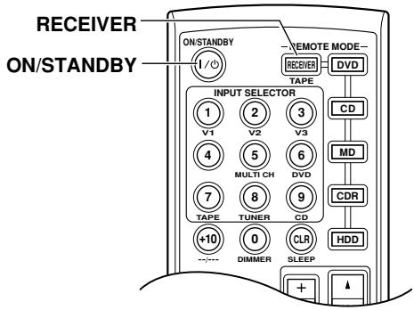
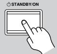
Turning On the AV Receiver
1
AV receiver
or
Remote
controller
ON/STANDBY

Press the [STANDBY/ON] button.
Alternatively, press the remote controller's [RECEIVER] button followed by the [ON/STANDBY] button.
The AV receiver comes on, the display lights up, and the STANDBY indicator goes off.
To turn the AV receiver off, press the [STANDBY/ON] button, or the remote controller's [ON/STANDBY] button. The AV receiver will enter Standby mode. To prevent any loud surprises the next time you turn on the AV receiver, always turn down the volume before turning it off.
Smooth Operation in a Few Easy Steps
To ensure smooth operation, here's a few easy steps to help you configure the AV receiver before you use it for the very first time. These settings only need to be made once.
Have you connected a component to a digital audio input?
If you have, see "Assigning Digital Inputs to Input Sources" on page 38.


COAXIAL
OPTICAL
Have you connected an Onkyo MD recorder, CD recorder, or RI Dock?
If you have, see "Changing the Input Display" on page 38.
TAPE
CD recorder, MD recorder
Testing the speakers
To test that all of the speakers are working properly, press the remote controller's [TEST TONE] button.
The test tone will be output by each speaker in turn and the name of each speaker will appear on the display. To turn off the test tone, press the [TEST TONE] button again.
- If the test tone is not produced by a speaker, or it's produced by a speaker other than that shown on the display, you may have wired the speakers incorrectly and you should check your connections (see page 21).
- If the test tone is not produced by a speaker and its name does not appear on the display, you may have set the speaker settings incorrectly (see page 55).
Assigning Digital Inputs to Input Sources
To enjoy Dolby Digital and DTS, you must connect your DVD player to the AV receiver by using a digital audio connection (coaxial or optical).
Here are the default assignments.
| Input selector | Default assignment |
| DVD | COAX |
| VIDEO 1/OCR | ---- |
| VIDEO 2 | OPT 1 |
| VIDEO 3 | ---- |
| TAPE | ---- |
| CD | OPT 2 |
With this function, you can assign digital inputs to input sources. For example, if you connect your DVD player to DIGITAL IN OPTICAL, you'll need to assign that input (OPT1) to the DVD input source.
You can change the assignments as follows.
Note:
Make sure you also set your digital sources to send out a digital signals. Please refer to the digital sources' manual.
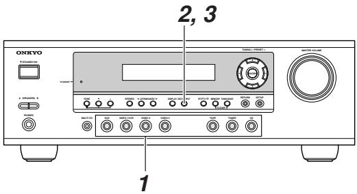
| 1 DVD VIDEO 1 YEAR VIDEO 2 VIDEO 3 TUNER CO | Press the input selector button for the source that you want to assign. (Digital inputs cannot be assigned to the TUNER input source.) |
| 2 DIGITAL INPUT | Press the [DIGITAL INPUT] button. The current assignment appears. |
| DVD #COAX | |
| 3 DIGITAL INPUT | Press the [DIGITAL INPUT] button repeatedly to select COAX, OPT1, OPT2, or “- - - ” (analog). |
| DVD #OPT1 |
Changing the Input Display
If you connect an RI-capable Onkyo MiniDisc recorder, CD recorder, or RI Dock to the TAPE IN/OUT or VIDEO 3 IN jacks, for RI to work properly, you must change this setting.
This setting can only be changed on the AV receiver.
iPod photo: If you're using an iPod photo with the DS-A1 Remote Interactive Dock, connect the DS-A1's SVIDEO jack directly to an S-Video input on your TV.
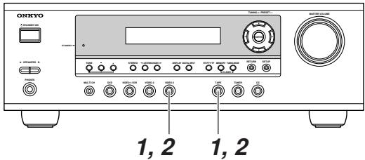
| 1 TAPE or VIDEO 3 | Press the [TAPE] or [VIDEO 3] input selector button so that “TAPE” or “VIDEO3” appears on the display. |
| TAPE | |
| VIDEOS3 |
| Press and hold down the [TAPE] or [VIDEO 3] input selector button (about 3 seconds) to change the setting. Repeat this step to select MD, CDR, or HDD. For the TAPE input selector, the setting changes in this order: TAPE → MD → CDR → HDD For the VIDEO 3 input selector, the setting changes in this order: VIDEO 3 → HDD |
Note:
HDD can be selected for the TAPE input selector orVIDEO 3 input selector, but not both at the same time.
Basic AV Receiver Operation

| 1 AV receiver Remote controller VIDEO 1VCR VIDEO 2 VIDEO 3 TAPE TUNER V1 V2 V3 DVD TAPE TUNER VIDEOS 1/2, and VIDEO 3 input sources respectively. | Use the AV receiver's input selector buttons to select the input source. To select the input source with the remote controller, press the [RECEIVER] button, and then use the INPUT SELECTOR buttons. On the remote controller, the [V1], [V2], and [V3] buttons select the VIDEO 1/VCR,VIDEO 2, andVIDEO 3 input sources respectively. | |
| 2 AV receiver Remote controller SP A/B A SPEAKERS B A receiver Remote controller VIDEO 1VCR VIDEO 2 VIDEO 3 TAPE TUNER VIDEOS 1/2, and VIDEO 3 input sources respectively. | Use the SPEAKERS [A] and [B] buttons on the AV receiver or the [SP A/B] button on the remote controller to select the speaker set that you want to use. Pressing the remote controller's [SP A/B] button cycles through the following settings: Speaker Set A → Speaker Set A&B → Speaker Set B → Off. The A and B speaker indicators show whether each speaker set is on or off. A B Indicators Note that when speaker set B is turned on, speaker set A is reduced to 2.1-channel playback. | |
| 3 | Start playback on the source component. When you select DVD or another video component, on your TV you'll need to select the video input that's connected to the AV receiver's MONITOR OUT. | |
| 4 AV receiver Remote controller VIDEOS 1/2, and VIDEO 3 A receiver Remote controller VIDEO 1/2, and VIDEO 3 VIDEOS 1/2, and VIDEO 3 VIDEOS 1/2, and VIDEO 3 VIDEOS 1/2, and VIDEO 3 VIDEOS 1/2, and VIDEO 3 VIDEOS 1/2, and VIDEO 3 VIDEOS 1/2, and VIDEO 3 VIDEOS 1/2, and VIDEO 3 VIDEOS 0/1, and VIDEO 0/2, and VIDEO 0/3, and VIDEO 0/4, and VIDEO 0/5, and VIDEO 0/6, and VIDEO 0/7, and VIDEO 0/8, and VIDEO 0/9, and VIDEO 0/10, and VIDEO 0/11, and VIDEO 0/12, and VIDEO 0/13, and VIDEO 0/14, and VIDEO 0/15, and VIDEO 0/16, and VIDEO 0/17, and VIDEO 0/18, and VIDEO 0/19, and VIDEO 0/20, and VIDEO 0/21, and VIDEO 0/22, and VIDEO 0/23, and VIDEO 0/24, and VIDEO 0/25, and VIDEO 0/26, and VIDEO 0/27, and VIDEO 0/28, and VIDEO 0/29, and VIDEO 0/30, and VIDEO 0/31, and VIDEO 0/32, and VIDEO 0/33, and VIDEO 0/34, and VIDEO 0/35, and VIDEO 0/36, and VIDEO 0/37, and VIDEO 0/38, and VIDEO 0/39, and VIDEO 0/40, and VIDEO 0/41, and VIDEO 0/42, and VIDEO 0/43, and VIDEO 0/44, and VIDEO 0/45, and VIDEO 0/46, and VIDEO 0/47, and VIDEO 0/48, and VIDEO 0/49, and VIDEO 0/50, and VIDEO 0/51, and VIDEO 0/52, and VIDEO 0/53, and VIDEO 0/54, and VIDEO 0/55, and VIDEO 0/56, and VIDEO 0/57, and VIDEO 0/58, and VIDEO 0/59, and VIDEO 0/60, and VIDEO 0/61, and VIDEO 0/62, and VIDEO 0/63, and VIDEO 0/64, and VIDEO 0/65, and VIDEO 0/66, and VIDEO 0/67, and VIDEO 0/68, and VIDEO 0/69, and VIDEO 0/70, and VIDEO 0/71, and VIDEO 0/72, and VIDEO 0/73, and VIDEO 0/74, and VIDEO 0/75, and VIDEO 0/76, and VIDEO 0/77, and VIDEO 0/78, and VIDEO 0/79, and VIDEO 0/80, and VIDEO 0/81, and VIDEO 0/82, and VIDEO 0/83, and VIDEO 0/84, and VIDEO 0/85, and VIDEO 0/86, and VIDEO 0/87, and VIDEO 0/88, and VIDEO 0/89, and VIDEO 0/90, and VIDEO 0/91, and VIDEO 0/92, and VIDEO 0/93, and VIDEO 0/94, and VIDEO 0/95, and VIDEO 0/96, and VIDEO 0/97, and VIDEO 0/98, and VIDEO 0/99, and VIDEO 100, and VIDEO 101, and VIDEO 102, and VIDEO 103, and VIDEO 104, and VIDEO 105, and VIDEO 106, and VIDEO 107, and VIDEO 108, and VIDEO 109, and VIDEO 110, and VIDEO 111, and VIDEO 112, and VIDEO 113, and VIDEO 114, and VIDEO 115, and VIDEO 116, and VIDEO 117, and VIDEO 118, and VIDEO 119, and VIDEO 120, and VIDEO 121, and VIDEO 122, and VIDEO 123, and VIDEO 124, and VIDEO 125, and VIDEO 126, and VIDEO 127, and VIDEO 128, and VIDEO 129, and VIDEO 130, and VIDEO 131, and VIDEO 132, and VIDEO 133, and VIDEO 134, and VIDEO 135, and VIDEO 136, and VIDEO 137, and VIDEO 138, and VIDEO 139, and VIDEO 140, and VIDEO 141, and VIDEO 142, and VIDEO 143, and VIDEO 144, and VIDEO 145, and VIDEO 146, and VIDEO 147, and VIDEO 148, and VIDEO 149, and VIDEO 150, and VIDEO 151, and VIDEO 152, and VIDEO 153, and VIDEO 154, and VIDEO 155, and VIDEO 156, and VIDEO 157, and VIDEO 158, and VIDEO 159, and VIDEO 160, and VIDEO 161, and VIDEO 162, and VIDEO 163, and VIDEO 164, and VIDEO 165, and VIDEO 166, and VIDEO 167, and VIDEO 168, and VIDEO 169, and VIDEO 170, and VIDEO 171, and VIDEO 172, and VIDEO 173, and VIDEO 174, and VIDEO 175, and VIDEO 176, and VIDEO 177, and VIDEO 178, and VIDEO 179, and VIDEO 180, and VIDEO 181, and VIDEO 182, and VIDEO 183, and VIDEO 184, and VIDEO 185, and VIDEO 186, and VIDEO 187, and VIDEO 188, and VIDEO 189, and VIDEO 190, and VIDEO 191, and VIDEO 192, and VIDEO 193, and VIDEO 194, and VIDEO 195, and VIDEO 196, and VIDEO 197, and VIDEO 198, and VIDEO 199, and VIDEO 200, and VIDEO 201, and VIDEO 202, and VIDEO 203, and VIDEO 204, and VIDEO 205, and VIDEO 206, and VIDEO 207, and VIDEO 208, and VIDEO 209, and VIDEO 210, and VIDEO 211, and VIDEO 212, and VIDEO 213, and VIDEO 214, and VIDEO 215, and VIDEO 216, and VIDEO 217, and VIDEO 218, and VIDEO 219, and VIDEO 220, and VIDEO 221, and VIDEO 222, and VIDEO 223, and VIDEO 224, and VIDEO 225, and VIDEO 226, and VIDEO 227, and VIDEO 228, and VIDEO 229, and VIDEO 230, and VIDEO 231, and VIDEO 232, and VIDEO 233, and VIDEO 234, and VIDEO 235, and VIDEO 236, and VIDEO 237, and VIDEO 238, and VIDEO 239, and VIDEO 240, and VIDEO 241, and VIDEO 242, and VIDEO 243, and VIDEO 244, and VIDEO 245, and VIDEO 246, and VIDEO 247, and VIDEO 248, and VIDEO 249, and VIDEO 250, and VIDEO 251, and VIDEO 252, and VIDEO 253, and VIDEO 254, and VIDEO 255, and VIDEO 256, and VIDEO 257, and VIDEO 258, and VIDEO 259, and VIDEO 260, and VIDEO 261, and VIDEO 262, and VIDEO 263, and VIDEO 264, and VIDEO 265, and VIDEO 266, and VIDEO 267, and VIDEO 268, and VIDEO 269, and VIDEO 270, and VIDEO 271, and VIDEO 272, and VIDEO 273, and VIDEO 274, and VIDEO 275, and VIDEO 276, and VIDEO 277, and VIDEO 278, and VIDEO 279, and VIDEO 280, and VIDEO 281, and VIDEO 282, and VIDEO 283, and VIDEO 284, and VIDEO 285, and VIDEO 286, and VIDEO 287, and VIDEO 288, and VIDEO 289, and VIDEO 290, and VIDEO 291, and VIDEO 292, and VIDEO 293, and VIDEO 294, and VIDEO 295, and VIDEO 296, and VIDEO 297, and VIDEO 298, and VIDEO 299, and VIDEO 300, and VIDEO 301, and VIDEO 302, and VIDEO 303, and VIDEO 304, and VIDEO 305, and VIDEO 306, and VIDEO 307, and VIDEO 308, and VIDEO 309, and VIDEO 310, and VIDEO 311, and VIDEO 312, and VIDEO 313, and VIDEO 314, and VIDEO 315, and VIDEO 316, and VIDEO 317, and VIDEO 318, and VIDEO 319, and VIDEO 320, and VIDEO 321, and VIDEO 322, and VIDEO 323, and VIDEO 324, and VIDEO 325, and VIDEO 326, and VIDEO 327, and VIDEO 328, and VIDEO 329, and VIDEO 330, and VIDEO 331, and VIDEO 332, and VIDEO 333, and VIDEO 334, and VIDEO 335, and VIDEO 336, and VIDEO 337, and VIDEO 338, and VIDEO 339, and VIDEO 340, and VIDEO 341, and VIDEO 342, and VIDEO 343, and VIDEO 344, and VIDEO 345, and VIDEO 346, and VIDEO 347, and VIDEO 348, and VIDEO 349, and VIDEO 350, and VIDEO 351, and VIDEO 352, and VIDEO 353, and VIDEO 354, and VIDEO 355, and VIDEO 356, and VIDEO 357, and VIDEO 358, and VIDEO 359, and VIDEO 360, and VIDEO 361, and VIDEO 362, and VIDEO 363, and VIDEO 364, and VIDEO 365, and VIDEO 366, and VIDEO 367, and VIDEO 368, and VIDEO 369, and VIDEO 370, and VIDEO 371, and VIDEO 372, and VIDEO 373, and VIDEO 374, and VIDEO 375, and VIDEO 376, and VIDEO 377, and VIDEO 378, and VIDEO 379, and VIDEO 380, and VIDEO 381, and VIDEO 382, and VIDEO 383, and VIDEO 384, and VIDEO 385, and VIDEO 386, and VIDEO 387, and VIDEO 388, and VIDEO 389, and VIDEO 390, and VIDEO 391, and VIDEO 392, and VIDEO 393, and VIDEO 394, and VIDEO 395, and VIDEO 396, and VIDEO 397, and VIDEO 398, and VIDEO 399, and VIDEO 400, and VIDEO 401, and VIDEO 402, and VIDEO 403, and VIDEO 404, and VIDEO 405, and VIDEO 406, and VIDEO 407, and VIDEO 408, and VIDEO 409, and VIDEO 410, and VIDEO 411, and VIDEO 412, and VIDEO 413, and VIDEO 414, and VIDEO 415, and VIDEO 416, and VIDEO 417, and VIDEO 418, and VIDEO 419, and VIDEO 420, and VIDEO 421, and VIDEO 422, and VIDEO 423, and VIDEO 424, and VIDEO 425, and VIDEO 426, and VIDEO 427, and VIDEO 428, and VIDEO 429, and VIDEO 430, and VIDEO 431, and VIDEO 432, and VIDEO 433, and VIDEO 434, and VIDEO 435, and VIDEO 436, and VIDEO 437, and VIDEO 438, and VIDEO 439, and VIDEO 440, and VIDEO 441, and VIDEO 442, and VIDEO 443, and VIDEO 444, and VIDEO 445, and VIDEO 446, and VIDEO 447, and VIDEO 448, and VIDEO 449, and VIDEO 450, and VIDEO 451, and VIDEO 452, and VIDEO 453, and VIDEO 454, and VIDEO 455, and VIDEO 456, and VIDEO 457, and VIDEO 458, and VIDEO 459, and VIDEO 460, and VIDEO 461, and VIDEO 462, and VIDEO 463, and VIDEO 464, and VIDEO 465, and VIDEO 466, and VIDEO 467, and VIDEO 468, and VIDEO 469, and VIDEO 470, and VIDEO 471, and VIDEO 472, and VIDEO 473, and VIDEO 474, and VIDEO 475, and VIDEO 476, and VIDEO 477, and VIDEO 478, and VIDEO 479, and VIDEO 480, and VIDEO 481, and VIDEO 482, and VIDEO 483, and VIDEO 484, and VIDEO 485, and VIDEO 486, and VIDEO 487, and VIDEO 488, and VIDEO 489, and VIDEO 490, and VIDEO 491, and VIDEO 492, and VIDEO 493, and VIDEO 494, and VIDEO 495, and VIDEO 496, and VIDEO 497, and VIDEO 498, and VIDEO 499, and VIDEO 500, and VIDEO 501, and VIDEO 502, and VIDEO 503, and VIDEO 504, and VIDEO 505, and VIDEO 506, and VIDEO 507, and VIDEO 508, and VIDEO 509, and VIDEO 510, and VIDEO 511, and VIDEO 512, and VIDEO 513, and VIDEO 514, and VIDEO 515, and VIDEO 516, and VIDEO 517, and VIDEO 518, and VIDEO 519, and VIDEO 520, and VIDEO 521, and VIDEO 522, and VIDEO 523, and VIDEO 524, and VIDEO 525, and VIDEO 526, and VIDEO 527, and VIDEO 528, and VIDEO 529, and VIDEO 530, and VIDEO 531, and VIDEO 532, and VIDEO 533, and VIDEO 534, and VIDEO 535, and VIDEO 536, and VIDEO 537, and VIDEO 538, and VIDEO 539, and VIDEO 540, and VIDEO 541, and VIDEO 542, and VIDEO 543, and VIDEO 544, and VIDEO 545, and VIDEO 546, and VIDEO 547, and VIDEO 548, and VIDEO 549, and VIDEO 550, and VIDEO 551, and VIDEO 552, and VIDEO 553, and VIDEO 554, and VIDEO 555, and VIDEO 556, and VIDEO 557, and VIDEO 558, and VIDEO 559, and VIDEO 560, and VIDEO 561, and VIDEO 562, and VIDEO 563, and VIDEO 564, and VIDEO 565, and VIDEO 566, and VIDEO 567, and VIDEO 568, and VIDEO 569, and VIDEO 570, and VIDEO 571, and VIDEO 572, and VIDEO 573, and VIDEO 574, and VIDEO 575, and VIDEO 576, and VIDEO 577, and VIDEO 578, and VIDEO 579, and VIDEO 580, and VIDEO 581, and VIDEO 582, and VIDEO 583, and VIDEO 584, and VIDEO 585, and VIDEO 586, and VIDEO 587, and VIDEO 588, and VIDEO 589, and VIDEO 590, and VIDEO 591, and VIDEO 592, and VIDEO 593, and VIDEO 594, and VIDEO 595, and VIDEO 596, and VIDEO 597, and VIDEO 598, and VIDEO 599, and VIDEO 600, and VIDEO 601, and VIDEO 602, and VIDEO 603, and VIDEO 604, and VIDEO 605, and VIDEO 606, and VIDEO 607, and VIDEO 608, and VIDEO 609, and VIDEO 610, and VIDEO 611, and VIDEO 612, and VIDEO 613, and VIDEO 614, and VIDEO 615, and VIDEO 616, and VIDEO 617, and VIDEO 618, and VIDEO 619, and VIDEO 620, and VIDEO 621, and VIDEO 622, and VIDEO 623, and VIDEO 624, and VIDEO 625, and VIDEO 626, and VIDEO 627, and VIDEO 628, and VIDEO 629, and VIDEO 630, and VIDEO 631, and VIDEO 632, and VIDEO 633, and VIDEO 634, and VIDEO 635, and VIDEO 636, and VIDEO 637, and VIDEO 638, and VIDEO 639, and VIDEO 640, and VIDEO 641, and VIDEO 642, and VIDEO 643, and VIDEO 644, and VIDEO 645, and VIDEO 646, and VIDEO 647, and VIDEO 648, and VIDEO 649, and VIDEO 650, and VIDEO 651, and VIDEO 652, and VIDEO 653, and VIDEO 654, and VIDEO 655, and VIDEO 656, and VIDEO 657, and VIDEO 658, and VIDEO 659, and VIDEO 660, and VIDEO 661, and VIDEO 662, and VIDEO 663, and VIDEO 664, and VIDEO 665, and VIDEO 666, and VIDEO 667, and VIDEO 668, and VIDEO 669, and VIDEO 670, and VIDEO 671, and VIDEO 672, and VIDEO 673, and VIDEO 674, and VIDEO 675, and VIDEO 676, and VIDEO 677, and VIDEO 678, and VIDEO 679, and VIDEO 680, and VIDEO 681, and VIDEO 682, and VIDEO 683, and VIDEO 684, and VIDEO 685, and VIDEO 686, and VIDEO 687, and VIDEO 688, and VIDEO 689, and VIDEO 690, and VIDEO 691, and VIDEO 692, and VIDEO 693, and VIDEO 694, and VIDEO 695, and VIDEO 696, and VIDEO 697, and VIDEO 698, and VIDEO 699, and VIDEO 700, and VIDEO 701, and VIDEO 702, and VIDEO 703, and VIDEO 704, and VIDEO 705, and VIDEO 706, and VIDEO 707, and VIDEO 708, and VIDEO 709, and VIDEO 710, and VIDEO 711, and VIDEO 712, and VIDEO 713, and VIDEO 714, and VIDEO 715, and VIDEO 716, and VIDEO 717, and VIDEO 718, and VIDEO 719, and VIDEO 720, and VIDEO 721, and VIDEO 722, and VIDEO 723, and VIDEO 724, and VIDEO 725, and VIDEO 726, and VIDEO 727, and VIDEO 728, and VIDEO 729, and VIDEO 730, and VIDEO 731, and VIDEO 732, and VIDEO 733, and VIDEO 734, and VIDEO 735, and VIDEO 736, and VIDEO 737, and VIDEO 738, and VIDEO 739, and VIDEO 740, and VIDEO 741, and VIDEO 742, and VIDEO 743, and VIDEO 744, and VIDEO 745, and VIDEO 746, and VIDEO 747, and VIDEO 748, and VIDEO 749, and VIDEO 750, and VIDEO 751, and VIDEO 752, and VIDEO 753, and VIDEO 754, and VIDEO 755, and VIDEO 756, and VIDEO 757, and VIDEO 758, and VIDEO 759, and VIDEO 760, and VIDEO 761, and VIDEO 762, and VIDEO 763, and VIDEO 764, and VIDEO 765, and VIDEO 766, and VIDEO 767, and VIDEO 768, and VIDEO 769, and VIDEO 770, and VIDEO 771, and VIDEO 772, and VIDEO 773, and VIDEO 774, and VIDEO 775, and VIDEO 776, and VIDEO 777, and VIDEO 778, and VIDEO 779, and VIDEO 780, and VIDEO 781, and VIDEO 782, and VIDEO 783, and VIDEO 784, and VIDEO 785, and VIDEO 786, and VIDEO 787, and VIDEO 788, and VIDEO 789, and VIDEO 790, and VIDEO 791, and VIDEO 792, and VIDEO 793, and VIDEO 794, and VIDEO 795, and VIDEO 796, and VIDEO 797, and VIDEO 798, and VIDEO 799, and VIDEO 800, and VIDEO 801, and VIDEO 802, and VIDEO 803, and VIDEO 804, and VIDEO 805, and VIDEO 806, and VIDEO 807, and VIDEO 808, and VIDEO 809, and VIDEO 810, and VIDEO 811, and VIDEO 812, and VIDEO 813, and VIDEO 814, and VIDEO 815, and VIDEO 816, and VIDEO 817, and VIDEO 818, and VIDEO 819, and VIDEO 820, and VIDEO 821, and VIDEO 822, and VIDEO 823, and VIDEO 824, and VIDEO 825, and VIDEO 826, and VIDEO 827, and VIDEO 828, and VIDEO 829, and VIDEO 830, and VIDEO 831, and VIDEO 832, and VIDEO 833, and VIDEO 834, and VIDEO 835, and VIDEO 836, and VIDEO 837, and VIDEO 838, and VIDEO 839, and VIDEO 840, and VIDEO 841, and VIDEO 842, and VIDEO 843, and VIDEO 844, and VIDEO 845, and VIDEO 846, and VIDEO 847, and VIDEO 848, and VIDEO 849, and VIDEO 850, and VIDEO 851, and VIDEO 852, and VIDEO 853, and VIDEO 854, and VIDEO 855, and VIDEO 856, and VIDEO 857, and VIDEO 858, and VIDEO 859, and VIDEO 860, and VIDEO 861, and VIDEO 862, and VIDEO 863, and VIDEO 864, and VIDEO 865, and VIDEO 866, and VIDEO 867, and VIDEO 868, and VIDEO 869, and VIDEO 870, and VIDEO 871, and VIDEO 872, and VIDEO 873, and VIDEO 874, and VIDEO 875, and VIDEO 876, and VIDEO 877, and VIDEO 878, and VIDEO 879, and VIDEO 880, and VIDEO 881, and VIDEO 882, and VIDEO 883, and VIDEO 884, and VIDEO 885, and VIDEO 886, and VIDEO 887, and VIDEO 888, and VIDEO 889, and VIDEO 890, and VIDEO 891, and VIDEO 892, and VIDEO 893, and VIDEO 894, and VIDEO 895, and VIDEO 896, and VIDEO 897, and VIDEO 898, and VIDEO 899, and VIDEO 900, and VIDEO 901, and VIDEO 902, and VIDEO 903, and VIDEO 904, and VIDEO 905, and VIDEO 906, and VIDEO 907, and VIDEO 908, and VIDEO 909, and VIDEO 910, and VIDEO 911, and VIDEO 912, and VIDEO 913, and VIDEO 914, and VIDEO 915, and VIDEO 916, and VIDEO 917, and VIDEO 918, and VIDEO 919, and VIDEO 920, and VIDEO 921, and VIDEO 922, and VIDEO 923, and VIDEO 924, and VIDEO 925, and VIDEO 926, and VIDEO 927, and VIDEO 928, and VIDEO 929, and VIDEO 930, and VIDEO 931, and VIDEO 932, and VIDEO 933, and VIDEO 934, and VIDEO 935, and VIDEO 936, and VIDEO 937, and VIDEO 938, and VIDEO 939, and VIDEO 940, and VIDEO 941, and VIDEO 942, and VIDEO 943, and VIDEO 944, and VIDEO 945, and VIDEO 946, and VIDEO 947, and VIDEO 948, and VIDEO 949, and VIDEO 950, and VIDEO 951, and VIDEO 952, and VIDEO 953, and VIDEO 954, and VIDEO 955, and VIDEO 956, and VIDEO 957, and VIDEO 958, and VIDEO 959, and VIDEO 960, and VIDEO 961, and VIDEO 962, and VIDEO 963, and VIDEO 964, and VIDEO 965, and VIDEO 966, and VIDEO 967, and VIDEO 968, and VIDEO 969, and VIDEO 970, and VIDEO 971, and VIDEO 972, and VIDEO 973, and VIDEO 974, and VIDEO 975, and VIDEO 976, and VIDEO 977, and VIDEO 978, and VIDEO 979, and VIDEO 980, and VIDEO 981, and VIDEO 982, and VIDEO 983, and VIDEO 984, and VIDEO 985, and VIDEO 986, and VIDEO 987, and VIDEO 988, and VIDEO 989, and VIDEO 990, and VIDEO 991, and VIDEO 992, and VIDEO 993, and VIDEO 994, and VIDEO 995, and VIDEO 996, and VIDEO 997, and VIDEO 998, and VIDEO 999; Video: The remote control of the remote system (V1) is used to select the remote control for the remote system (V2). The remote control is used to select the remote control for the remote system (V3). The remote control is used to select the remote control for the remote system (V4). The remote control is used to select the remote control for the remote system (V5). The remote control is used to select the remote control for the remote system (V6). The remote control is used to select the remote control for the remote system (V7). The remote control is used to select the remote control for the remote system (V8). The remote control is used to select the remote control for the remote system (V9). The remote control is used to select the remote control for the remote system (V10). The remote control is used to select the remote control for the remote system (V11). The remote control is used to select the remote control for the remote system (V12). The remote control is used to select the remote control for the remote system (V13). The remote control is used to select the remote control for the remote system (V14). The remote control is used to select the remote control for the remote system (V15). The remote control is used to select the remote control for the remote system (V16). The remote control is used to select the remote control for the remote system (V17). The remote control is used to select the remote control for the remote system (V18). The remote control is used to select the remote control for the remote system (V19). The remote control is used to select the remote control for the remote system (V20). The remote control is used to select the remote control for the remote system (V21). The remote control is used to select the remote control for the remote system (V22). The remote control is used to select the remote control for the remote system (V23). The remote control is used to select the remote control for the remote system (V24). The remote control is used to select the remote control for the remote system (V25). The remote control is used to select the remote control for the remote system (V26). The remote control is used to select the remote control for the remote system (V27). The remote control is used to select the remote control for the remote system (V28). The remote control is used to select the remote control for the remote system (V29). The remote control is used to select the remote control for the remote system (V30). The remote control is used to select the remote control for the remote system (V31). The remote control is used to select the remote control for the remote system (V32). The remote control is used to select the remote control for the remote system (V33). The remote control is used to select the remote control for the remote system (V34). The remote control is used to select the remote control for the remote system (V35). The remote control is used to select the remote control for the remote system (V36). The remote control is used to select the remote control for the remote system (V37). The remote control is used to select the remote control for the remote system (V38). The remote control is used to select the remote control for the remote system (V39). The remote control is used to select the remote control for the remote system (V40). The remote control is used to select the remote control for the remote system (V41). The remote control is used to select the remote control for the remote system (V42). The remote control is used to select the remote control for the remote system (V43). The remote control is used to select the remote control for the remote system (V44). The remote control is used to select the remote control for the remote system (V45). The remote control is used to select the remote control for the remote system (V46). The remote control is used to select the remote control for the remote system (V47). The remote control is used to select the remote control for the remote system (V48). The remote control is used to select the remote control for the remote system (V49). The remote control is used to select the remote control for the remote system (V50). The remote control is used to select the remote control for the remote system (V51). The remote control is used to select the remote control for the remote system (V52). The remote control is used to select the remote control for the remote system (V53). The remote control is used to select the remote control for the remote system (V54). The remote control is used to select the remote control for the remote system (V55). The remote control is used to select the remote control for the remote system (V56). The remote control is used to select the remote control for the remote system (V57). The remote control is used to select the remote control for the remote system (V58). The remote control is used to select the remote control for the remote system (V59). The remote control is used to select the remote control for the remote system (V60). The remote control is used to select the remote control for the remote system (V61). The remote control is used to select the remote control for the remote system (V62). The remote control is used to select the remote control for the remote system (V63). The remote control is used to select the remote control for the remote system (V64). The remote control is used to select the remote control for the remote system (V65). The remote control is used to select the remote control for the remote system (V66). The remote control is used to select the remote control for the remote system (V67). The remote control is used to select the remote control for the remote system (V68). The remote control is used to select the remote control for the remote system (V69). The remote control is used to select the remote control for the remote system (V70). The remote control is used to select the remote control for the remote system (V71). The remote control is used to select the remote control for the remote system (V72). The remote control is used to select the remote control for the remote system (V73). The remote control is used to select the remote control for the remote system (V74). The remote control is used to select the remote control for the remote system (V75). The remote control is used to select the remote control for the remote system (V76). The remote control is used to select the remote control for the remote system (V77). The remote control is used to select the remote control for the remote system (V78). The remote control is used to select the remote control for the remote system (V79). The remote control is used to select the remote control for the remote system (V80). The remote control is used to select the remote control for the remote system (V81). The remote control is used to select the remote control for the remote system (V82). The remote control is used to select the remote control for the remote system (V83). The remote control is used to select the remote control for the remote system (V84). The remote control is used to select the remote control for the remote system (V85). The remote control is used to select the remote control for the remote system (V86). The remote control is used to select the remote control for the remote system (V87). The remote control is used to select the remote control for the remote system (V88). The remote control is used to select the remote control for the remote system (V89). The remote control is used to select the remote control for the remote system (V90). The remote control is used to select the remote control for the remote system (V91). The remote control is used to select the remote control for the remote system (V92). The remote control is used to select the remote control for the remote system (V93). The remote control is used to select the remote control for the remote system (V94). The remote control is used to select the remote control for the remote system (V95). The remote control is used to select the remote control for the remote system (V96). The remote control is used to select the remote control for the remote system (V97). The remote control is used to select the remote control for the remote system (V98). The remote control is used to select the remote control for the remote system (V99). The remote control is used to select the remote control for the remote system (V100). The remote control is used to select the remote control for the remote system (V101). The remote control is used to select the remote control for the remote system (V102). The remote control is used to select the remote control for the remote system (V103). The remote control is used to select the remote control for the remote system (V104). The remote control is used to select the remote control for the remote system (V105). The remote control is used to select the remote control for the remote system (V106). The remote control is used to select the remote control for the remote system (V107). The remote control is used to select the remote control for the remote system (V108). The remote control is used to select the remote control for the remote system (V109). The remote control is used to select the remote control for the remote system (V110). The remote control is used to select the remote control for the remote system (V111). The remote control is used to select the remote control for the remote system (V112). The remote control is used to select the remote control for the remote system (V113). The remote control is used to select the remote control for the remote system (V114). The remote control is used to select the remote control for the remote system (V115). The remote control is used to select the remote control for the remote system (V116). The remote control is used to select the remote control for the remote system (V117). The remote control is used to select the remote control for the remote system (V118). The remote control is used to select the remote control for the remote system (V119). The remote control is used to select the remote control for the remote system (V120). The remote control is used to select the remote control for the remote system (V121). The remote control is used to select the remote control for the remote system (V122). The remote control is used to select the remote control for the remote system (V123). The remote control is used to select the remote control for the remote system (V124). The remote control is used to select the remote control for the remote system (V125). The remote control is used to select the remote control for the remote system (V126). The remote control is used to select the remote control for the remote system (V127). The remote control is used to select the remote control for the remote system (V128). The remote control is used to select the remote control for the remote system (V129). The remote control is used to select the remote control for the remote system (V130). The remote control is used to select the remote control for the remote system (V131). The remote control is used to select the remote control for the remote system (V132). The remote control is used to select the remote control for the remote system (V133). The remote control is used to select the remote control for the remote system (V134). The remote control is used to select the remote control for the remote system (V135). The remote control is used to select the remote control for the remote system (V136). The remote control is used to select the remote control for the remote system (V137). The remote control is used to select the remote control for the remote system (V138). The remote control is used to select the remote control for the remote system (V139). The remote control is used to select the remote control for the remote system (V140). The remote control is used to select the remote control for the remote system (V141). The remote control is used to select the remote control for the remote system (V142). The remote control is used to select the remote control for the remote system (V143). The remote control is used to select the remote control for the remote system (V144). The remote control is used to select the remote control for the remote system (V145). The remote control is used to select the remote control for the remote system (V146). The remote control is used to select the remote control for the remote system (V147). The remote control is used to select the remote control for the remote system (V148). The remote control is used to select the remote control for the remote system (V149). The remote control is used to select the remote control for the remote system (V150). The remote control is used to select the remote control for the remote system (V151). The remote control is used to select the remote control for the remote system (V152). The remote control is used to select the remote control for the remote system (V153). The remote control is used to select the remote control for the remote system (V154). The remote control is used to select the remote control for the remote system (V155). The remote control is used to select the remote control for the remote system (V156). The remote control is used to select the remote control for the remote system (V157). The remote control is used to select the remote control for the remote system (V158). The remote control is used to select the remote control for the remote system (V159). The remote control is used to select the remote control for the remote system (V160). The remote control is used to select the remote control for the remote system (V161). The remote control is used to select the remote control for the remote system (V162). The remote control is used to select the remote control for the remote system (V163). The remote control is used to select the remote control for the remote system (V164). The remote control is used to select the remote control for the remote system (V165). The remote control is used to select the remote control for the remote system (V166). The remote control is used to select the remote control for the remote system (V167). The remote control is used to select the remote control for the remote system (V168). The remote control is used to select the remote control for the remote system (V169). The remote control is used to select the remote control for the remote system (V170). The remote control is used to select the remote control for the remote system (V171). The remote control is used to select the remote control for the remote system (V172). The remote control is used to select the remote control for the remote system (V173). The remote control is used to select the remote control for the remote system (V174). The remote control is used to select the remote control for the remote system (V175). The remote control is used to select the remote control for the remote system (V176). The remote control is used to select the remote control for the remote system (V177). The remote control is used to select the remote control for the remote system (V178). The remote control is used to select the remote control for the remote system (V179). The remote control is used to select the remote control for the remote system (V180). The remote control is used to select the remote control for the remote system (V181). The remote control is used to select the remote control for the remote system (V182). The remote control is used to select the remote control for the remote system (V183). The remote control is used to select the remote control for the remote system (V184). The remote control is used to select the remote control for the remote system (V185). The remote control is used to select the remote control for the remote system (V186). The remote control is used to select the remote control for the remote system (V187). The remote control is used to select the remote control for the remote system (V188). The remote control is used to select the remote control for the remote system (V189). The remote control is used to select the remote control for the remote system (V190). The remote control is used to select the remote control for the remote system (V191). The remote control is used to select the remote control for the remote system (V192). The remote control is used to select the remote control for the remote system (V193). The remote control is used to select the remote control for the remote system (V194). The remote control is used to select the remote control for the remote system (V195). The remote control is used to select the remote control for the remote system (V196). The remote control is used to select the remote control for the remote system (V197). The remote control is used to select the remote control for the remote system (V198). The remote control is used to select the remote control for the remote system (V199). The remote control is used to select the remote control for the remote system (V200). The remote control is used to select the remote control for the remote system (V201). The remote control is used to select the remote control for the remote system (V202). The remote control is used to select the remote control for the remote system (V203). The remote control is used to select the remote control for the remote system (V204). The remote control is used to select the remote control for the remote system (V205). The remote control is used to select the remote control for the remote system (V206). The remote control is used to select the remote control for the remote system (V207). The remote control is used to select the remote control for the remote system (V208). The remote control is used to select the remote control for the remote system (V209). The remote control is used to select the remote control for the remote system (V210). The remote control is used to select the remote control for the remote system (V211). The remote control is used to select the remote control for the remote system (V212). The remote control is used to select the remote control for the remote system (V213). The remote control is used to select the remote control for the remote system (V214). The remote control is used to select the remote control for the remote system (V215). The remote control is used to select the remote control for the remote system (V216). The remote control is used to select the remote control for the remote system (V217). The remote control is used to select the remote control for the remote system (V218). The remote control is used to select the remote control for the remote system (V219). The remote control is used to select the remote control for the remote system (V220). The remote control is used to select the remote control for the remote system (V221). The remote control is used to select the remote control for the remote system (V222). The remote control is used to select the remote control for the remote system (V223). The remote control is used to select the remote control for the remote system (V224). The remote control is used to select the remote control for the remote system (V225). The remote control is used to select the remote control for the remote system (V226). The remote control is used to select the remote control for the remote system (V227). The remote control is used to select the remote control for the remote system (V228). The remote control is used to select the remote control for the remote system (V229). The remote control is used to select the remote control for the remote system (V230). The remote control is used to select the remote control for the remote system (V231). The remote control is used to select the remote control for the remote system (V232). The remote control is used to select the remote control for the remote system (V233). The remote control is used to select the remote control for the remote system (V234). The remote control is used to select the remote control for the remote system (V235). The remote control is used to select the remote control for the remote system (V236). The remote control is used to select the remote control for the remote system (V237). The remote control is used to select the remote control for the remote system (V238). The remote control is used to select the remote control for the remote system (V239). The remote control is used to select the remote control for the remote system (V240). The remote control is used to select the remote control for the remote system (V241). The remote control is used to select the remote control for the remote system (V242). The remote control is used to select the remote control for the remote system (V243). The remote control is used to select the remote control for the remote system (V244). The remote control is used to select the remote control for the remote system (V245). The remote control is used to select the remote control for the remote system (V246). The remote control is used to select the remote control for the remote system (V247). The remote control is used to select the remote control for the remote system (V248). The remote control is used to select the remote control for the remote system (V249). The remote control is used to select the remote control for the remote system (V250). The remote control is used to select the remote control for the remote system (V251). The remote control is used to select the remote control for the remote system (V252). The remote control is used to select the remote control for the remote system (V253). The remote control is used to select the remote control for the remote system (V254). The remote control is used to select the remote control for the remote system (V255). The remote control is used to select the remote control | ||
Using the Multichannel Input
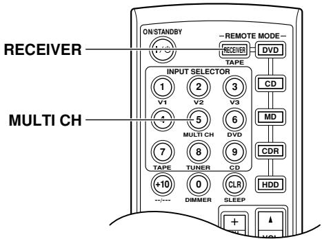
The multichannel input is for connecting a component with individual 5.1-channel analog audio output jacks, such as a DVD player or MPEG decoder. See page 29 for hookup information.
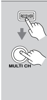
Press the [RECEIVER] button followed by the [MULTI CH] button so that MULTI CH indicator appears on the display.
Audio from the multichannel input will now be used for the DVD input source.
![ONKYO HT-S3105 - Press the [RECEIVER] button followed by the [MULTI CH] button so that MULTI CH indicator appears on the display. - 1](/content/2025/01/151736/images/943b7681f3689b5391b7b502533a326de2ae1a2ed308f7998e081bbe9443a47b.jpg)
Note:
- While the multichannel input is selected, the Speaker Configuration settings on page 55 are ignored, and signals from the multichannel input are fed to the front left, front right, center, surround left, and surround right speakers and subwoofer regardless of those settings.
Displaying Source Information
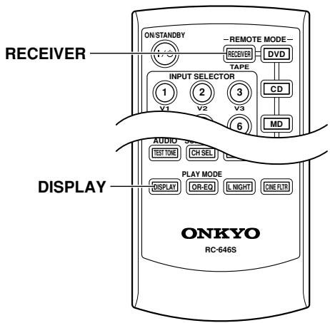
You can display various information about the current input source as follows.
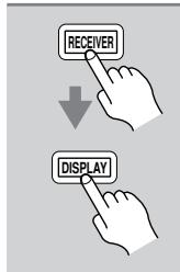
Press the [RECEIVER] button, and then press the [DISPLAY] button repeatedly to cycle through the available information.
The following information can typically be displayed for input sources.
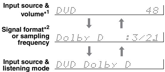
1 When AM or FM radio is used, the band, preset number, and frequency are displayed.
2 If the input signal is analog, or AM or FM radio is selected, no format information is displayed. If the input signal is PCM, the sampling frequency is displayed. If the input signal is digital but not PCM, the signal format is displayed. Information is displayed for about 3 seconds, then the previous display reappears.
Interpreting Surround Channel Information
$$ \begin{array}{c c c} \hline \hline \hline \hline \hline \hline \hline \hline \hline \hline \hline \hline \hline \hline \hline \hline \hline \hline \hline \hline \hline \hline \hline \hline \hline \hline \hline \hline \hline \hline \hline \hline \hline \hline \ \hline A & B & C \ \hline \end{array} $$
A: The number of front channels (front left, front right, and center).
B: The number of surround channels (surround left and surround right). If there's surround back channel information, this number will be 3.
C: LFE channel for subwoofer (1 means yes).
Listening to the Radio
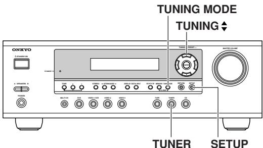
With the built-in tuner, you can enjoy AM and FM radio stations. You can store your favorite stations as presets for quick selection.

1
TUNER
Use the [TUNER] input selector button to select either AM or FM. In this example, FM has been selected.
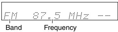
(Actual display depends on country.)
AM Frequency Step Setup (not North America and Europe)
Here you can specify the AM frequency step used in your area. When this setting is changed, all radio presets are deleted.
| 1 | Press the [SETUP] button to dis-play “0. Hardware Setup,” and then press [ENTER]. |
| 2 | Use the Up and Down [▲]/[▼] buttons to select “AM Freq,” and then use the Left and Right [▲]/[▼] buttons to select: 10 kHz: Select if 10 kHz steps are used in your area. 9 kHz: Select if 9 kHz steps are used in your area. |
| 3 | Press the [SETUP] button. Setup closes. |
Note:
- This procedure can also be performed on the remote controller by using its [SETUP] button, arrow buttons, and [ENTER] button.
Tuning into Radio Stations
Auto Tuning Mode
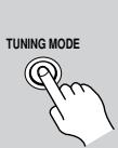
1
Press the [TUNING MODE] button so that the AUTO indicator appears on the display.
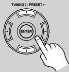
2
Press the TUNING Up or Down [] / [] button.
Searching stops when a station is found.
Manual Tuning Mode

1
Press the [TUNING MODE] button so that the AUTO indicator disappears from the display.
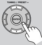
2
Press and hold the TUNING Up or Down [▲]/[▼] button.
The frequency stops changing when you release the button.
Press the buttons repeatedly to change the frequency one step at a time.
The American model changes FM frequency in 0.2 MHz steps, 10kHz steps for AM. For other models it's 0.05MHz steps for FM and 9kHz or 10kHz steps for AM.
When tuned into a station, the TUNED indicator appears. When tuned into a stereo FM station, the FM STEREO indicator appears on the display, as shown.
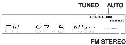
Tuning into weak FM stereo stations
If the signal from a stereo FM station is weak, it may be impossible to get good reception. In this case, switch to Manual Tuning mode and listen to the station in mono.
Note:
- You can also use the remote controller's Up and Down [▲]/[▼] buttons to tune the radio.
Presetting Radio Stations
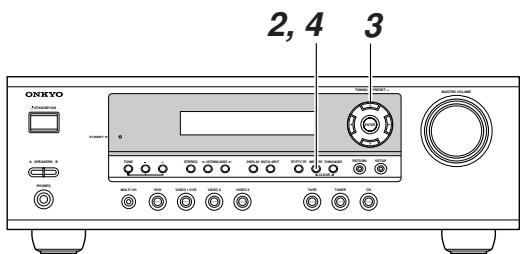
You can store up to 30 of your favorite radio stations as presets.
| 1 | Tune into the station that you want to store as a preset. |
| 2 | Press the [MEMORY] button. The MEMORY indicator appears and the preset number flashes. |
| 3 | While the MEMORY indicator is displayed (about 8 seconds), use the PRESET [▲]/[▷] buttons to select a preset from 1 through 30. In this example, preset #3 is selected. |
| 4 | Press the [MEMORY] button again to store the station. The station is stored and the preset number stops flashing. Repeat this procedure for all your favorite radio stations. |
Selecting Preset Stations
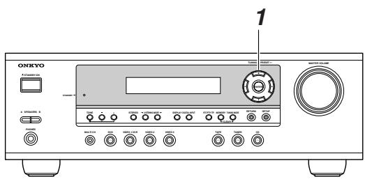
| 1 TUNING: PRESET... | Use the PRESET [▲]/[▶] but-tons, or the remote controller's CH [+/−] button to select a preset. |
Deleting Presets

| 1 | Select the preset that you want to delete. See the previous section. |
| 2 MEMORY TUNING MODE CLEAR | While holding down the [MEM-ORY] button, press the [TUNING MODE] button. The selected preset is deleted and its number disappears from the display. |
Displaying Radio Information
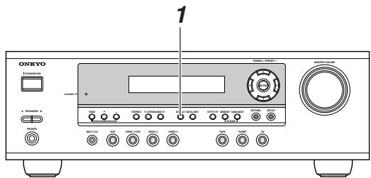
| 1 DISPLAY | Press the [DISPLAY] button repeatedly to cycle through the available information. |
Band, preset # & frequency
Listening mode
| FM 83.1 MHz 1 |
| ↑ ↓ |
| STEREO |
| FM Stereo |
Using RDS (European models only)
RDS only works with European models and only in areas where RDS broadcasts are available. When tuned into an RDS station, the RDS indicator appears.
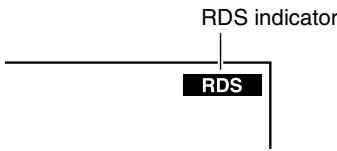
What is RDS?
RDS stands for Radio Data System and is a method of transmitting data in FM radio signals. It was developed by the European Broadcasting Union (EBU) and is available in most European countries. Many FM stations use it these days. In addition to displaying text information, RDS can also help you find radio stations by type (e.g., news, sport, rock, etc.).
The AV receiver supports four types of RDS information:
PS (Program Service)
When tuned to an RDS station that's broadcasting PS information, the station's name appears. When you press the [DISPLAY] button, the frequency is displayed for three seconds.
RT (Radio Text)
When tuned to an RDS station that's broadcasting RT text information, that information is shown on the display (see page 44).
PTY (Program Type)
You can also search for radio stations by type (see page 44).
TP (Traffic Program)
You can also search for TP radio stations (see page 44).
Notes:
- In some cases, the text characters displayed on the AV receiver may not be identical to those broadcast by the radio station. Also, unexpected characters may be displayed when unsupported characters are received. This is not a malfunction.
- If the signal from an RDS station is weak, RDS data may be displayed intermittently or not at all.
Program Types Used in Europe (PTY)
| Type | Display | Description |
| None | NONE | No program type. |
| News reports | NEWS | Reports on current events and happenings. |
| Current affairs | AFFAIRS | Topical reporting of current affairs, often with a wider range of topics than news reports. |
| Information | INFO | General information such as weather forecasts, consumer affairs, medical help, etc. |
| Sport | SPORT | Live sports action, sports news, and interviews. |
| Education | EDUCATE | Formal educational programs. |
| Drama | DRAMA | Radio plays and serials. |
| Culture | CULTURE | Cultural programs (including religious affairs). |
| Science and technology | SCIENCE | Programs about the natural sciences and technology. |
| Varied | VARIED | Speech-based programs not covered by the above categories (e.g., quizzes, panel games, and comedy). |
| Pop music | POP M | Popular commercial music, usually from past or present sales charts (e.g., Top 40). |
| Rock music | ROCK M | Popular music with an alternative appeal, often not appearing on sales charts. |
| Middle of the road music | M.O.R.M | Easy listening music (as opposed to Pop, Rock, or Classical). |
| Light classics | LIGHT M | Classical music for general rather than specialist appreciation. |
| Serious classics | CLASSICS | Performances of major orchestral works, symphonies, chamber music, etc. (including the Grand Opera). |
| Other music | OTHER M | Music styles not covered by the above categories (e.g., Jazz, Rhythm & Blues, Folk, Country, and Reggae). |
| Alarm | ALARM | When an RDS station is making an emergency broadcast, ALARM will flash on the display. |
Displaying Radio Text (RT)
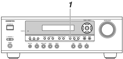
When tuned to an RDS station that's broadcasting RT text information, that information can be displayed.
1
RT/PTY/TP

Press the [RT/PTY/TP] button once.
The RT information scrolls across the display.
Notes:
- The message "Waiting" may appear while the AV receiver waits for RT information.
- If the message "No Text Data" appears on the display, no RT information is available.
Finding Stations by Type (PTY)
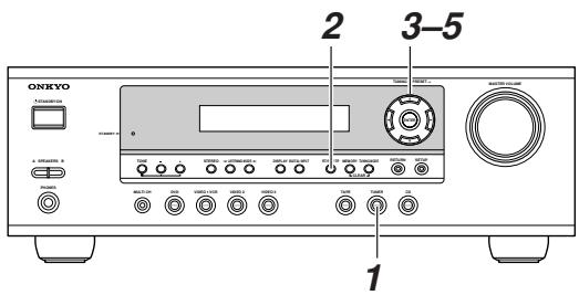
You can search for radio stations by type.
1
TUNER

Use the [TUNER] input selector button to select FM.
2
RT/PTY/TP
![ONKYO HT-S3105 - Use the [TUNER] input selector button to select FM. - 1](/content/2025/01/151736/images/9c01f79385da416bfee301c40972daab68b945e6ee8f3d880a5c2829b926a13e.jpg)
Press the [RT/PTY/TP] button twice.
The current program type appears on the display.
3
![ONKYO HT-S3105 - Press the [RT/PTY/TP] button twice. - 1](/content/2025/01/151736/images/349bf0210aeaaeb01fea610ede2b3c819c92a133037d3d0a0482a1b2d61f9312.jpg)
Use the PRESET [] / [] buttons to select the type of program you want.
See the table on page 43.
4
![ONKYO HT-S3105 - Use the PRESET [] / [] buttons to select the type of program you want. - 1](/content/2025/01/151736/images/5c0e6f8fa83af0af03db85bb371191237e77404140c4dc8c34cd967df83c0fde.jpg)
To start the search, press [ENTER].
The AV receiver searches until it finds a station of the type you specified, at which point it stops briefly before continuing with the search.
5
![ONKYO HT-S3105 - To start the search, press [ENTER]. - 1](/content/2025/01/151736/images/682157550f5f419b9ec4dbf4e3d563dd92ad74ffb466fc6746bbb71f59f0928e.jpg)
When a station you want to listen to is found, press [ENTER].
If no stations are found, the message "Not Found" appears.
Listening to Traffic News (TP)
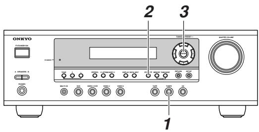
You can search for TP radio stations.
1

Use the [TUNER] input selector button to select FM.
2
![ONKYO HT-S3105 - Use the [TUNER] input selector button to select FM. - 1](/content/2025/01/151736/images/02577677f30ffa675f649d319d6235db693c9ad4ae8a56de370a1f41e883ef23.jpg)
Press the [RT/PTY/TP] button three times.
If the current radio station is broadcasting TP (Traffic Program), "[TP]" will appear on the display, and traffic news will be heard as and when it's broadcast. If "TP" without square brackets appears, this means that the station is not broadcasting TP.
3
![ONKYO HT-S3105 - Press the [RT/PTY/TP] button three times. - 1](/content/2025/01/151736/images/9741a30234cba1e35f6cf57867fb32e3ca10e3b12bf872ef2bb669acb034fc8a.jpg)
To locate a station that is broadcasting TP, press [ENTER].
The AV receiver searches until it finds a station that's broadcasting TP.
If no stations are found, the message "Not Found" appears.
This chapter explains functions that can be used with any input source.
![ONKYO HT-S3105 - To locate a station that is broadcasting TP, press [ENTER]. - 1](/content/2025/01/151736/images/ae4c51406fef5ccc864d3f82c11dc1d21f2d2c45ae3e4b6fd3bb5dd86804d1e5.jpg)
Using Headphones
You can connect a pair of stereo headphones (1/4-inch phone plug) to the AV receiver's PHONES jack for private listening, as shown.

Notes:
- Always turn down the volume before connecting your headphones.
- Speaker sets A and B are turned off while the headphones plug is inserted in the PHONES jack.
- When you connect a pair of headphones, the listening mode is set to Stereo, unless it's already set to Mono, Stereo, or Direct.
- When the multichannel DVD input is selected, only the front left and front right channels can be heard in the headphones.
Setting the Display Brightness
With this function, you can adjust the brightness of the display.
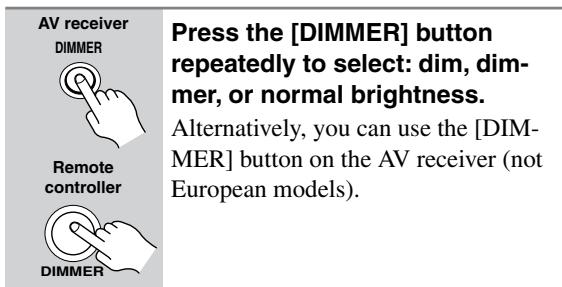
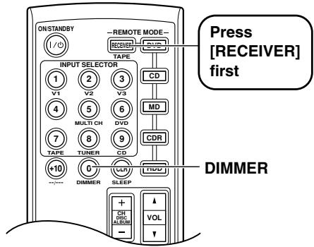
Adjusting the Bass & Treble
You can adjust the bass or treble for speaker set A's front speakers, except when the Direct listening mode is selected.
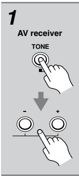
Press the AV receiver's [TONE] button repeatedly to select either Bass or Treble. Use the TONE [-]/[+] buttons to adjust.

Bass
You can boost or cut low-frequency sounds output by the front speakers from -10dB to +10dB in 2 dB steps.

Treble
You can boost or cut high-frequency sounds output by the front speakers from -10dB to +10dB in 2 dB steps.
Note:
- To bypass the bass and treble tone circuits, select the Direct listening mode.
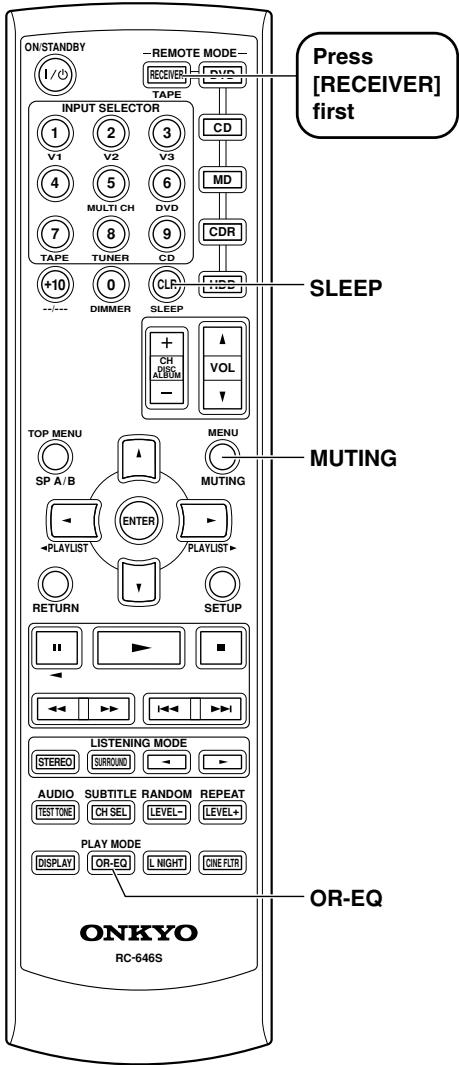
Muting the AV Receiver
With this function, you can temporarily mute the output of the AV receiver.
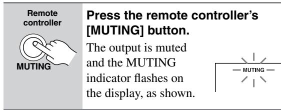
To unmute the AV receiver, press the remote controller's [MUTING] button again, or adjust the volume. The output is unmuted and the MUTING indicator goes off. Muting is cancelled when the AV receiver is set to Standby.
Using the Sleep Timer
With the sleep timer, you can set the AV receiver so that it automatically turns off after a set period.

To cancel the sleep timer, press the [SLEEP] button repeatedly until the SLEEP indicator disappears.
To check the remaining sleep time, press the [SLEEP] button. Note that if you press the [SLEEP] button while the sleep time is being displayed, you'll shorten the sleep time by 10 minutes.
Using the OptiResponse Equalizer
When using the HT-R340 with the speakers included in the HTP-360/HTP-318 Home Theater Speaker Package, by turning on the OptiResponse equalizer, you can enjoy a powerful sound with movies or music.
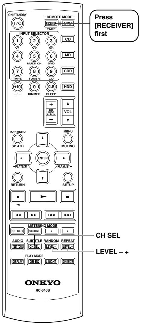
Adjusting Speaker Levels
You can adjust the level of each speaker in speaker set A while listening to an input source. These temporary adjustments are cancelled when the AV receiver is set to Standby.
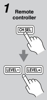
Use the remote controller's [CH SEL] button to select each speaker, and use the [LEVEL-] and [LEVEL+] buttons to adjust the volume.
You can adjust the volume of each speaker from -12dB to +12dB (-15dB to +12dB for the subwoofer).
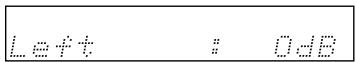
Notes:
- You cannot use this function while the AV receiver is muted.
- Speakers that are set to No or None in the Speaker Configuration cannot be adjusted.
Speaker Set B
While speaker set B is on, you can also adjust the levels of the left and right speakers in speaker set B, from -12dB to +12dB .
- These settings are stored when the AV receiver is set to Standby.
- While speaker set B is on, you can adjust the levels of the left and right speakers in speaker set A's and the subwoofer.
Headphones
While a pair of headphones is connected, you can adjust the volume of the left and right channels individually, from -12dB to +12dB each.
- These settings are stored when the AV receiver is set to Standby.
Multichannel DVD Input
While the multichannel DVD input is selected, you can adjust the level of each 5.1 channel input individually, from -12dB to +12dB . (-30 to +12dB for the subwoofer.)
- These settings are stored when the AV receiver is set to Standby.
- Individual speaker levels can also be adjusted in "3. MultiLevel Setup" (see page 54).
This chapter explains how to record the selected input source to an AV component with recording capability, and how to record audio and video from two different sources.
Recording the Input Source
You can record only to AV components that are connected to the TAPE OUT or VIDEO 1 OUT jacks.
See pages 26-36 for information on connecting your AV components to the AV receiver.
| 1 DVD VIDEO 1/VCR VIDEO 2 VIDEO 3 TAPE TURER Remote controller V1 V2 V3 DVD TAPE TURER CD | Use the input selector buttons to select the AV component that you want to record. Audio signals from the selected input source are output by the VIDEO 1 OUT and TAPE OUT jacks. You can listen to the source while recording. The AV receiver's VOL-UME control has no effect on recording. |
| 2 | Start recording on the AV component connected to the TAPE OUT or VIDEO 1 OUT jacks. |
| 3 | Start playback on the source AV component. |
Notes:
- You cannot record from AV components that are connected to the digital inputs. You must use analog connections.
- The surround effects produced by the surround and DSP listening modes cannot be recorded.
- You cannot record from an AV component that is connected to the multichannel input.
- If you select another input source while recording, that input source will be recorded instead.
Recording from Different AV Sources
With this function, you can record audio and video from different sources, allowing you to overdub audio onto your video recordings. This function takes advantage of the fact that when an audio-only input source (i.e., TAPE, TUNER, or CD) is selected, the video input source remains unchanged. For example, if you first select the VIDEO 3 input source, followed by the CD input source, you can watch the video from the VIDEO 3 input and listen to the audio from the CD input.
In the following example, audio from the CD player connected to the CD IN jacks, and video from the camcorder connected to the VIDEO 3 IN jack are recorded by the VCR, which is connected to the VIDEO 1 OUT jacks.
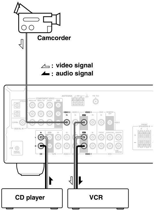
- Prepare the camcorder and CD player for playback.
- Prepare the VCR for recording.
- Press the [VIDEO 3] input selector button.
- Press the [CD] input selector button.
This selects the CD player as the audio source, but leaves the camcorder as the video source.
- Start recording on the VCR and start playback on the camcorder and CD player.
The video from the camcorder and the audio from the CD player are recorded by the VCR.
Selecting Listening Modes
See "About the Listening Modes" on page 50 for detailed information about the listening modes.
- The Dolby Digital and DTS listening modes can only be selected if your DVD player is connected to the AV receiver with a digital audio connection (coaxial or optical).
- Listening mode availability depends on the format of the current input signal.
- While a pair of headphones is connected, you can select only the Mono, Direct, or Stereo listening mode.
- While speaker B is on, you can select only the Direct or Stereo listening mode.
- The listening modes cannot be selected while speaker set A is off.
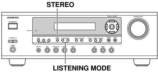
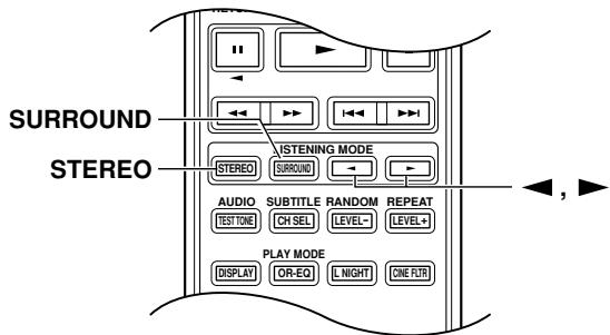
[STEREO] button
This button selects the Stereo listening mode.
[SURROUND] button (remote controller only)
This button selects the Dolby Digital and DTS listening modes.
LISTENING MODE [<] buttons
Pressing these buttons repeatedly cycles through all of the listening modes that can be used with the current input source.
The following table lists all the listening modes and shows which modes can be selected for each input signal format.
| Input signal format | Analog, PCM*1 | Dolby D | DTS/DTS 96/24*2 | Multich | |||||||
| */2 | 2/0 (Stereo) | 1/0,1+1 | Other | 3/2.1 | 2/0 (Stereo) | DTS-ES | |||||
| Discrete | Matrix | ||||||||||
| Source Listening mode | CD, TV, VHS, MD, turntable, radio, cassette, DTV, etc. | DVD, DTV, etc. | DVD, CD, etc. | DVD | |||||||
| Direct | ✓ | ✓ | ✓ | ✓ | ✓ | ✓ | ✓ | ✓ | ✓ | ✓ | |
| Stereo Mono | ✓ | ✓ | ✓ | ✓ | ✓ | ✓ | ✓ | ✓ | |||
| Multich | ✓ | ||||||||||
| PLII Movie/Music/Game Neo:6 Cinema Neo:6 Music | ✓ | ✓ | ✓ | ||||||||
| Dolby D | ✓ | ✓ | |||||||||
| DTS | ✓ | ✓ | |||||||||
| Onkyo Original DSP | Mono Movie Orchestra Unplugged Studio-Mix TV Logic All Ch Stereo Full Mono | ✓ | ✓ | ✓ | ✓ | ✓ | ✓ | ✓ | ✓ | ||
1. In the Direct listening modes, PCM signals at 32kHz , 44.1kHz , and 48kHz are processed at 64kHz , 88.2kHz , and 96kHz respectively. 96kHz signals are processed at 48kHz for all listening modes other than Direct, and Stereo.
2. DTS 96/24 is always processed as DTS.
Tip: You can check the format of the digital input signal on page 40, "Displaying Source Information."
About the Listening Modes
With its built-in surround-sound decoders and DSP programs, the AV receiver can transform your home listening room into a movie theater or concert hall.
This illustration shows which speakers are active in each listening mode.
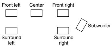
Direct
The selected input source is output directly with minimal processing for a pure sound.
Stereo
The selected input source is processed as a stereo signal and output by the front left and right speakers and the subwoofer.
Mono
Use this mode when watching an old movie with a mono soundtrack, or to select multilingual soundtracks recorded in the left and right channels of some movies. It can also be used when playing a DVD or other source with multiplexed audio, such as a karaoke DVD.
Dolby Pro Logic II Movie
Use this mode with DVDs and videos that bear the Dolby Surround
logo or TV shows that feature Dolby Surround. You can also use this mode with stereo movies or TV shows and the AV receiver will create a 5.1 surround mix from the 2-channel stereo.
Dolby Pro Logic II Music
Use this mode to add 5.1 surround to stereo sources such as music CDs and DVDs.
Dolby Pro Logic II Game
Use this mode when playing game discs.
Dolby Digital
With this format you can experience the same superb sound that you get at a movie theater or concert hall. Use this mode with DVDs that bear the Dolby Digital logo.
DTS
This digital surround format offers a surround sound experience with exceptional fidelity. It uses compressed digital audio data, with six discrete channels (5.1), and the ability to handle large amounts of audio data while remaining faithful to the original. DTS provides very high-quality sound. You'll need a DTS compatible DVD
player in order to enjoy DTS material. Use this mode with DVDs and CDs that bear the DTS logo.
Neo:6
This mode provides 5.1-channel playback from 2-channel sources. It offers five full-bandwidth channels with excellent separation. There are two modes of operation: Cinema mode for movies, and Music mode for listening to music.
Cinema mode simulates the realistic sense of movement that you get with 5.1-channel surround sound sources. Use this mode with videos, DVDs, and TV shows that feature stereo sound.
Music mode uses the surround channels to simulate a natural sound field that cannot be produced with conventional stereo. Use this mode with stereo material such as music CDs.
Onkyo Original DSP Modes
Mono Movie

This mode is suitable for use with old movies and other mono sound sources. The center speaker outputs the sound as it is, while reverb is applied to the sound output by the other speakers, giving presence to even mono material.
Orchestra
Suitable for classical or operatic music. The surround channels are emphasized in order to widen the stereo image. In addition, it simulates the natural reverberation of a large hall.
Unplugged

Suitable for acoustic instrument sounds, vocals, and jazz music. By emphasizing the front stereo image, it simulates the stage-front experience.
Studio-Mix

Suitable for rock and pop music. Listening to music in this mode creates a lively sound field with a powerful acoustic image, like being at a club or rock concert.
TV Logic

Adds realistic acoustics to TV shows produced in a TV studio. In addition, it adds surround effects to the entire sound and adds clarity to voices.
All Ch Stereo

Ideal for background music. The front, surround, and surround back channels create a stereo image that fills the entire listening area.
Full Mono

In this mode, all speakers output mono audio, so the music sounds the same regardless of where you are.
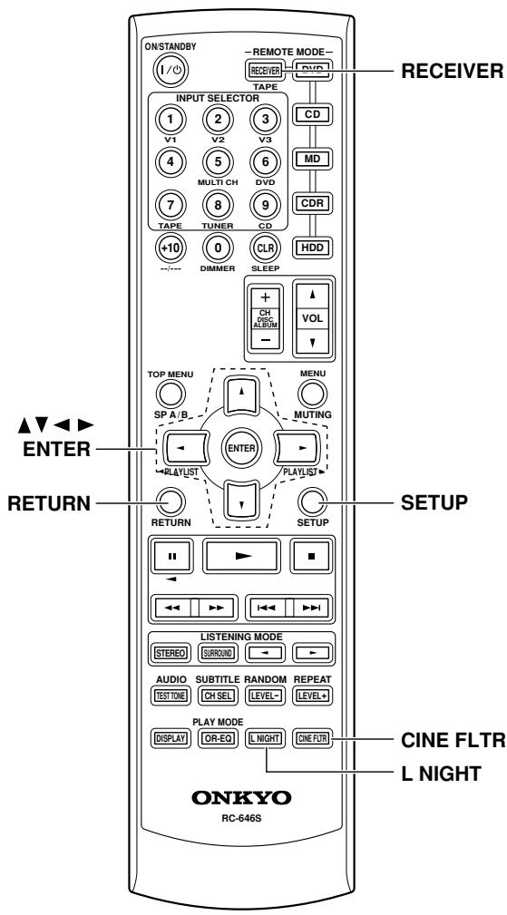
Using the Audio Adjust Functions
Some functions are not available with all speaker configurations.
Audio Adjust provides various functions for adjusting the sound.
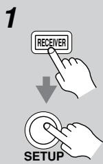
Press the [RECEIVER] button followed by the [SETUP] button.
Use the Up and Down [ ] / [ ] buttons to select "4. Audio Adjust," and then press the [ENTER] button.

4. P C i O . P&W.
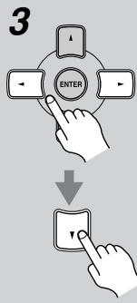
Repeat step 3 to complete all settings.
Use the Left and Right [] / [] buttons to change the settings. Press the Down [▼] button to select the next setting.
4
5

Press the [SETUP] button. Setup closes.
When you want to go back up one menu level to "Audio Adjust," press the [RETURN] button.
The Audio Adjust functions are explained below.
Input Channel Settings
Multiplex
This setting determines which channel is output from a stereo multiplex source. Use it to select audio channels or languages with multiplex sources, multilingual TV broadcasts, and so on.
Main: The main channel is output (default).
Sub: The sub channel is output.
M/S: Both the main and sub channels are output.
Mono (2ch)
This setting determines which channel is output when the Mono listening mode is used with a stereo source.
L + R : Both the left and right channels are output (default).
L: Only the left channel is output.
R: Only the right channel is output.
PLII Music Mode Settings
These settings apply to only 2-channel (stereo) sources.
Panorama
With this function, you can broaden the width of the front stereo image when using the Pro Logic II Music listening mode.
On: Panorama function on.
Off: Panorama function off (default).
Dimension
With this setting, you can move the sound field forward or backward when using the Pro Logic II Music listening mode. The default setting is 3. It can be adjusted from 0 to 6. Higher settings move the sound field forward.
Lower settings move it backward.
If the stereo image feels too wide, or there's too much surround sound, move the sound field forward to improve the balance. Conversely, if the stereo image feels like it's in mono, or there's not enough surround sound, move it backward.
Center Width
This setting has an effect when you use a center speaker. With this function, you can adjust the width of the sound from the center speaker when using the Pro Logic II
Music listening mode normally. If you're using a center speaker, the center channel sound is output by only the center speaker. (If you're not using a center speaker, the center channel sound will be distributed to the front left and right speakers to create a phantom center). This setting controls the front left, right, and center mix, allowing you to adjust the weight of the center channel sound. It can be adjusted from 0 to 7 (default is 3).
DTS Neo:6 Music Mode Setting
Center Image
This setting has an effect when you use a center speaker.
The DTS Neo:6 Music listening mode creates 5-channel surround sound from 2-channel (stereo) sources. With this setting, you can specify by how much the front left and right channel output is attenuated in order to create the center channel. It can be adjusted from 0 to 5 (default is 2). This setting is unavailable if no surround speakers are connected.
When set to 0, the front left and right channel output is attenuated by half (-6dB) , giving the impression that the sound is located centrally. This setting works well when the listening position is considerably off center. When set to 5, the front left and right channels are not attenuated, maintaining the original stereo balance.
Using the Late Night Function (Dolby Digital only)
With the Late Night function, you can reduce the dynamic range of Dolby Digital material so that you can still hear quiet parts even when listening at low volume levels—ideal for watching movies late at night when you don't want to disturb anyone.
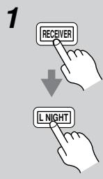
Press the [RECEIVER] button, and then press the [L NIGHT] button repeatedly to select:
Off: Late Night function off.
Low: Small reduction in dynamic range.
High: Big reduction in dynamic range.
Notes:
- The effect of the Late Night function depends on the Dolby Digital material that you are playing, and with some material there will be little or no effect.
- The Late Night function is set to Off when the AV receiver is set to Standby.
Using the CinemaFILTER
With the CinemaFILTER, you can soften overly bright movie soundtracks, which are typically mixed for reproduction in a movie theater.
CinemaFILTER can be used with the following listening modes: Dolby Digital, Dolby PLII Movie, DTS, and DTS Neo:6 Cinema.
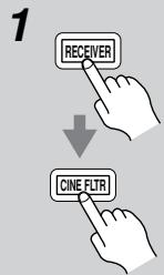
Press the [RECEIVER] button, and then press the [CINE FLTR] button repeatedly to select:
On: CinemaFILTER on.
Off: CinemaFILTER off.
![ONKYO HT-S3105 - Press the [RECEIVER] button, and then press the [CINE FLTR] button repeatedly to select: - 1](/content/2025/01/151736/images/e0b2cb6060a74852b2201a31ad5fd1f85bb763f4c3e5fd12995baa2c6859ab63.jpg)
Advanced Speaker Settings
Speaker Distance
The speaker distance setting cannot be changed while a pair of headphones is connected, speaker set B is on, or the multichannel input is being used.
To get the best from surround sound, it's important that the sound from each speaker reaches the listener at the same time. To achieve this, you need to specify the distance from each speaker to the listening position.
| 1 | Measure and make a note of the distance from each speaker to the listening position. |
| 2 | Press the [RECEIVER] button followed by the [SETUP] button on the remote controller. |
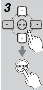
Use the Up and Down [ ] / [ ] buttons to select "2. SP Distance," and then press the [ENTER] button.
2.5F Distance
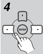
While "Unit" is displayed, use the Left and Right [<]按钮 to select feet or meters.
feet: Distances in feet. Can be set from 1 to 30 feet in 1-foot steps.
meters: Distances in meters. Can be set from 0.3 to 9 meters in 0.3-meter steps.
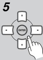
Use the Down [▼] button to select "Front," and use the Left and Right [▲]/[▶] buttons to specify the distance for the "front speakers," then press the Down [▼] button to select the next speaker.
6
Repeat step 5 for all speakers. Note:
Speakers that you set to No or None in the Speaker Configuration (page 55) cannot be selected.
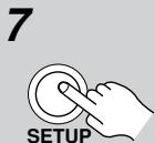
Press the [SETUP] button.
Setup closes.
When you want to go back up one menu level to "SP Distance," press the [RETURN] button.
Notes:
- The Center and Subwoofer distances can be set up to 5 ft. (1.5 m) more or less than the Front distance. For example, if the Front distance is set to 20 ft. (6 m), the Center and Subwoofer distances can be set between 15 and 25 ft. (4.5 and 7.5 m).
- The Surround distances can be set up to 5 ft. (1.5 m) more or 15 ft. (4.5 m) less than the Front distance. For example, if the Front distance is set to 20 ft. (6 m), the SurrRight and Surr Left distances can be set between 5 and 25 ft. (1.5 and 7.5 m).
Speaker Levels
With this function, you can adjust the volume of each speaker so that all speakers can be heard equally at the listening position.
The speaker levels cannot be adjusted while a pair of headphones is connected, speaker set B is on, or the AV receiver is muted.
| 1 | Press the [RECEIVER] button followed by the [SETUP] button on the remote controller. |
| 2 | Use the Up and Down [▲]/[▼] buttons to select “3. Level Cal,” and then press the [ENTER] button. A pink noise test tone is output by the front left speaker. 3. Level Cal |
| 3 | Turn up the volume so that you can hear the test tone sufficiently. While each speaker outputs the test tone, its name appears on the display, as shown. Left: 0 dB Right: 1 dB |
| 4 | Use the Left and Right [▲]/[▼] buttons to adjust the speaker level, and use the Down [▼] button to select the next speaker. The level can be adjusted from -12 to +12 dB in 1 dB steps (-15 to +12 dB for the subwoofer). |
| 5 | Repeat step 4 so that the level of the test tone from each speaker is the same. Speakers that you set to No or None in the Speaker Configuration (page 55) do not output the test tone. |
| 6 | Press the [SETUP] button. Setup closes. Don’t forget to turn down the volume if you turned it up while setting the levels. When you want to go back up one menu level to “Level Cal,” press the [RETURN] button. |
Note:
- A quicker way to adjust the speaker levels is to press the remote controller's [TEST TONE] button to output the test tone, use the [LEVEL-] and [LEVEL+] buttons to adjust the levels, and use the [CH SEL] button to select the speakers.
- If the multichannel input is selected (page 40), in step 2, the "3. MultiLevel" menu appears instead of the "3. Level Cal" menu, and you can adjust the level of each channel of the multichannel input regardless of the Speaker Configuration settings.
You can adjust the volume of each speaker from -12dB to +12dB (-30dB to +12dB for the subwoofer).
Speaker Configuration, Crossover Frequency, and Double Bass settings only need to be changed if you're not using the speakers in this package.
These settings cannot be changed while headphones are connected, speaker set B is on, or the multichannel DVD input is being used.
Speaker Configuration
This section explains how to specify your speaker configuration.
For speakers with a cone diameter larger than 6-1/2 inches (16 cm), specify Large (full band). For those with a smaller diameter, specify Small (default crossover 100Hz ).
The crossover frequency can be changed on page 56.
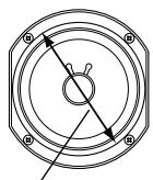
Cone diameter
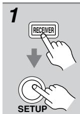
Press the [RECEIVER] button followed by the [SETUP] button.

Use the Up and Down [] / [] buttons to select "1. SP Config," and then press the [ENTER] button.
1.5P Conf ig
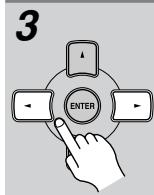
While the Subwoofer setting is selected, use the Left and Right [<]/[▶] buttons to select Yes or No.
Yes: Select if a subwoofer is connected.
No: Select if no subwoofer is connected.
4
Use the Down [▼] button to select “Front,” and then use the Left and Right [▲]/[▶] buttons to select Small or Large.
Small: Select if the front speakers are small.
Large: Select if the front speakers are large.
Note:
- If the Subwoofer setting in step 3 is set to No, this setting is fixed at Large and does not appear.
5
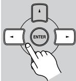
Use the Down [▼] button to select “Center,” and then use the Left and Right [▲]/[▶] buttons to select Small, Large, or None.
Small: Select if the center speaker is small.
Large: Select if the center speaker is large.
None: Select if no center speaker is connected.
Note:
- If the Front setting in step 4 is set to Small, the Large option cannot be selected.
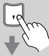
6
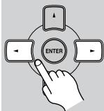
Use the Down [▼] button to select "Surround," and then use the Left and Right [▲]/[▶] buttons to select Small, Large, or None.
Small: Select if the surround speakers are small.
Large: Select if the surround speakers are large.
None: Select if no surround speakers are connected.
Note:
- If the Front setting in step 4 is set to Small, the Large option cannot be selected.
Continue with step 7 of the "Crossover Frequency" setting.
Crossover Frequency
This setting only applies to the speakers that you specified as Small in the "Speaker Configuration" on page 55. To get the best bass performance from your speaker system, you need to set the crossover frequency according to the size and frequency response of your speakers.
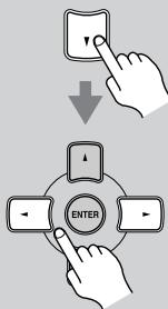
7
Use the Down [▼] button to select "Crossover," and then use the Left and Right [▲]/[▶] buttons to select a crossover frequency.
Use the diameter of the smallest speaker in your system when choosing the crossover frequency.
| Speaker cone diameter | Crossover frequency |
| Over 8 in. (20 cm) | 40/50/60Hz* |
| 6-1/2 to 8 in. (16-20 cm) | 80Hz |
| 5-1/4 to 6-1/2 in. (13-16 cm) | 100Hz |
| 3-1/2 to 5-1/4 in. (9-13 cm) | 120Hz (default) |
| Under 3-1/2 in. (9 cm) | 150/200Hz* |
*Choose the setting suitable for the speaker.
Continue with step 8 of the "Double Bass" setting below.
Notes:
- For a more accurate setting, look up the frequency response in the manuals supplied with your speakers and set accordingly.
- Choose a higher crossover frequency if you want more sound from your subwoofer.
Double Bass
With the Double Bass function, you can boost bass output by feeding bass sounds from the front left and right channels to the subwoofer. This function can be set only if the Subwoofer setting (step 3) is set to Yes, and the Front setting (step 4) is set to Large in the Speaker Configuration on page 55.
8
Use the Down [▼] button to select "Double Bass," and then use the Left and Right [▲]/[▶] buttons to select:
On: Double Bass function on. Bass from the front left and right channels is also fed to the subwoofer (default).
Off: Double Bass function off.
![ONKYO HT-S3105 - Use the Down [▼] button to select "Double Bass," and then use the Left and Right [▲]/[▶] buttons to select: - 1](/content/2025/01/151736/images/6ae406a618c3d34a144aa0d8253cd0c8df8fcddd5e21fe5518be338768ae4222.jpg)
![ONKYO HT-S3105 - Use the Down [▼] button to select "Double Bass," and then use the Left and Right [▲]/[▶] buttons to select: - 2](/content/2025/01/151736/images/506c04e9392488e464954d95f5e92e65950731c70d240991938f21ca018a45ee.jpg)
9
Press the [SETUP] button.
Setup closes.
When you want to go back up one menu level to "SP Config," press the [RETURN] button.
Digital Input Signal Formats
The following table shows the display indicators for each supported digital signal format.
| Format | Display |
| Dolby Digital | D D |
| DTS | D T S |
| PCM | PCM |
Normally, the AV receiver detects the signal format automatically. However, if you experience either of the following issues when playing PCM or DTS material, you can manually set the signal format to PCM or DTS:
- If the beginnings of tracks from a PCM source are cut off, try setting the format to PCM.
- If noise is produced when fast forwarding or reversing a DTS CD, try setting the format to DTS.
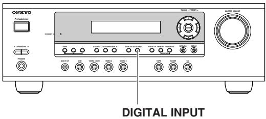
1 Press and hold the AV receiver's [DIGITAL INPUT] button for about 3 seconds.
2 While "Auto" is displayed (about 3 seconds), press the [DIGITAL INPUT] button again to select: PCM, DTS, or Auto.
DTS or PCM: The DTS or PCM indicator, depending on which format you have set, flashes, and only signals in that format are output. Digital signals in other formats are ignored.
Auto (default): The format is detected automatically. If no digital input signal is present, the corresponding analog input is used instead.
Correcting Sound and Picture Sync
When using progressive scanning on your DVD player, you may find that the picture and sound are out of sync. With this setting, you can correct this by delaying the audio signals. You can set it to 0, 20, or 40 milliseconds.
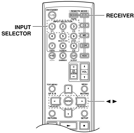
Press the [RECEIVER] REMOTE MODE button.
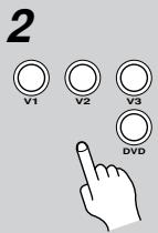
Press and hold, for more than 4 seconds, the input selector button for the input source that you want to correct.
This can be the [DVD], [VIDEO 1], [VIDEO 2], or [VIDEO 3] input source.
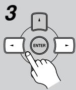
Use the Left and Right [] / [] buttons to set the delay to 0, 20, or 40 milliseconds.
DUD AUSync#20ms
The previous display reappears if you don't do anything for 5 minutes.
Note:
- This setting is not available when the Direct listening mode is used with an analog input signal.
If you have any trouble using the AV receiver, look for a solution in this section.
If you can't resolve the issue yourself, try resetting the AV receiver before contacting your Onkyo dealer. To reset the AV receiver to its factory defaults, turn it on and, while holding down the [VIDEO 1] button, press the [STANDBY/ON] button. "Clear" will appear on the display and the AV receiver will enter Standby mode.
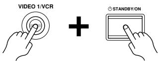
Note that resetting the AV receiver will delete your radio presets and custom settings.
Power
Can't turn on the AV receiver?
- Make sure that the power cord is properly plugged into the wall outlet.
- Unplug the power cord from the wall outlet, wait five seconds or more, then plug it in again.
The AV receiver turns off as soon as it's turned on?
- The amp protection circuit has been activated. Remove the power cord from the wall outlet immediately. Disconnect all speaker cables and input sources, and leave the AV receiver with its power cord disconnected for one hour. After that, reconnect the power cord, and then set the volume to maximum. If the AV receiver stays on, set the volume to minimum, disconnect the power cord, and reconnect your speakers and input sources properly. If the AV receiver turns off when you set the volume to maximum, disconnect the power cord, and contact your Onkyo dealer.
Audio
There's no sound or it's very quiet?
- Press the SPEAKERS [A] or [B] button to turn on the indicator for the speakers that you want to output sound.
- Make sure that the digital input source is selected properly (page 38). Press the [DIGITAL INPUT] button repeatedly.
- Make sure that all audio connecting plugs are pushed in all the way (page 26).
- Make sure that the polarity of the speaker cables is correct, and that the bare wires are in contact with metal part of each speaker terminal (page 21)
-
Make sure that the speaker cables are not shorting.
-
Check the volume. The AV receiver is designed for home theater enjoyment and has a wide volume range for precise adjustment (page 39).
- If the MUTING indicator is shown on the display, press the remote controller's [MUTING] button to unmute the AV receiver (page 46).
- While a pair of headphones is connected to the PHONES jack, no sound is output by the speakers (page 45).
- Check the digital audio output setting on the connected device. On some games consoles, such as those that can play DVDs, the default setting is off.
- With some DVD-Video discs, you need to select an audio format from a menu.
- If your turntable doesn't have a phono preamp built-in, you must connect one between it and the AV receiver. If your turntable uses an MC cartridge, you must connect an MC head amp, or an MC transformer and a phono preamp.
- Specify the speaker distances and adjust the individual speaker levels (pages 53, 54).
- The input signal format is set to PCM or DTS. Set it to Auto (page 57).
Only the front speakers produce sound?
- When the Stereo or Mono listening mode is selected, only the front speakers and subwoofer produce sound.
- Make sure the speakers are configured correctly (page 55).
Only the center speaker produces sound?
- If you use the Pro Logic II Movie or Pro Logic II Music listening mode with a mono source, such as an AM radio station or mono TV program, the sound is concentrated in the center speaker.
- Make sure the speakers are configured correctly (page 55).
The surround speakers produce no sound?
- When the Stereo or Mono listening mode is selected, the surround speakers produce no sound (page 50).
- Depending on the source and current listening mode, not much sound may be produced by the surround speakers. Try selecting another listening mode.
- Make sure the speakers are configured correctly (page 55).
The center speaker produces no sound?
- When the Stereo or Mono listening mode is selected, the center speaker produces no sound (page 50).
- Make sure the speakers are configured correctly (page 55).
The subwoofer produces no sound?
- The subwoofer outputs no sound while only speaker set B is on. Turn on speaker set A.
- When you play source material that contains no information in the LFE channel, the subwoofer produces no sound.
- Make sure the speakers are configured correctly (page 55).
- If the multichannel DVD input is selected and speaker set B is on, speaker set A is reduced to 2-channel playback, so the subwoofer outputs no sound.
- On the AV receiver, the subwoofer setting in the speaker configuration is set to No. Set the subwoofer setting to Yes.
There's no sound with a certain signal format?
- Check the digital audio output setting on the connected device. On some games consoles, such as those that can play DVDs, the default setting is off.
- With some DVD-Video discs, you need to select an audio output format from a menu.
Can't get 5.1-channel playback?
- When speaker B is turned on, speaker set A is reduced to 2.1-channel playback.
The volume cannot be set to 79?
- When the subwoofer volume level is set to a positive (+) value, the maximum master volume level is reduced proportionally.
Noise can be heard?
- Using cable ties to bundle audio cables with power cords, speaker cables, and so on may degrade the audio performance, so don't do it.
- An audio cable may be picking up interference. Try repositioning your cables.
The Late Night function doesn't work?
- Make sure the source material is Dolby Digital (page 52).
The DVD analog multichannel input doesn't work?
- Check the DVD analog multichannel input connections (page 29).
- To select the DVD analog multichannel input, press the [MULTI CH] input selector button (page 40).
- Check the audio output settings on your DVD player.
About DTS signals
- When DTS program material ends and the DTS bitstream stops, the AV receiver remains in DTS listening mode and the DTS indicator remains on. This is to prevent noise when you use the pause, fast forward, or fast reverse function on your player. If you switch your player from DTS to PCM, because the AV receiver does not switch formats immediately, you may not hear
any sound, in which case you should stop your player for about three seconds, and then resume playback.
- With some CD players, you won't be able to playback DTS material properly even though your player is connected to a digital input on the AV receiver. This is usually because the DTS bitstream has been processed (e.g., output level, sampling rate, or frequency response changed) and the AV receiver doesn't recognize it as a genuine DTS signal. In such cases, you may hear noise.
- When playing DTS program material, using the pause, fast forward, or fast reverse function on your player may produce a short audible noise. This is not a malfunction.
Video
There's no picture?
- Make sure that all video connecting plugs are pushed in all the way (page 26).
- Make sure that each video component is properly connected.
- The AV receiver does not convert between formats, so if a video source component is connected to a component video input, your TV must be connected to the component video output (page 27).
- On your TV, make sure that the video input to which the AV receiver is connected is selected.
Tuner
Reception is noisy, stereo FM reception suffers from hiss, or the FM STEREO indicator doesn't appear?
- Relocate your antenna.
- Move the AV receiver away from your TV or computer.
- Listen to the station in mono (page 41).
- When listening to an AM station, operating the remote controller may cause noise.
Passing cars and airplanes can cause interference.
Concrete walls weaken radio signals. - If nothing improves the reception, install an outdoor antenna (page 25).
Remote Controller
The remote controller doesn't work?
- Make sure that the batteries are installed with the correct polarity (page 19).
- Make sure that the remote controller is not too far away from the AV receiver, and that there's no obstruction between the remote controller and the AV receiver's remote control sensor (page 19).
- Make sure you've selected the correct remote controller mode (page 12).
- Make sure you've entered the correct remote control code.
Can't control other components?
- Make sure you've selected the correct remote controller mode (page 12).
- If you've connected an RI -capable Onkyo MD recorder, CD recorder, or next generation HDD-compatible component to the TAPE IN/OUT jacks, or a DS-A1 Remote Interactive Dock to the VIDEO 3 IN jacks, for the remote controller to work properly, you must set the Input Display to MD, CDR, or HDD (see page 38).
- To control an Onkyo component that's connected via RI, point the remote controller at the AV receiver.
RI Dock for the iPod
There's no sound
- Make sure your iPod is actually playing.
- Make sure your iPod is inserted properly in the RI Dock.
- Make sure the RI Dock is connected to the correct input jacks on the AV receiver. Do not connect it to any output jacks.
- Make sure the AV receiver is turned on, the correct input source is selected, and the volume is turned up.
- Make sure the plugs are pushed in all the way.
- Make sure the AC adapter is connected to a suitable wall outlet and connected to the RI Dock.
Try resetting your iPod.
There's no video
- Make sure that your iPod's TV OUT setting is set to On.
- Make sure the correct input is selected on your TV or the AV receiver.
- Some versions of the iPod do not output video.
The AV receiver's remote controller doesn't control your iPod
- 3rd generation iPods are not supported.
- Make sure your iPod is properly inserted in the RI Dock. If your iPod is in a case, it may not connect
properly to the RI Dock. Always remove your iPod from the case before inserting it into the RI Dock.
- The iPod cannot be operated while it's displaying the Apple logo.
- Make sure you've selected the right remote mode.
- Check the RI Dock's RI MODE switch setting.
- When you use the AV receiver's remote controller, point it toward your amp.
- The RI Dock must be connected to the AV receiver with both an RI cable and an audio cable.
- If you still can't control your iPod, start playback by pressing your iPod's Play button. Remote operation should then be possible.
The AV receiver unexpectedly selects your iPod as the input source
- Always pause iPod playback before selecting a different input source. If playback is not paused, the Direct Change function may select your iPod as the input source by mistake during the transition between tracks.
Recording
Can't record?
- On your recorder, make sure the correct input is selected.
- To prevent signal loops and damage to the AV receiver, input signals are not fed through to outputs with the same name (e.g., TAPE IN to TAPE OUT, or VIDEO 1 IN to VIDEO 1 OUT).
Others
The sound changes when I connect my headphones?
- When a pair of headphones is connected, the listening mode is set to Stereo, unless it's already set to Stereo, Mono, Direct.
How do I change the language of a multiplex source?
- Use the "Multiplex" setting on the "4. Audio Adjust" menu to select Main or Sub (page 51).
The RI functions don't work?
- To use RI, you must make an RI connection and an analog audio connection (RCA) between the component and AV receiver, even if they are connected digitally (page 36).
The AV receiver contains a microcomputer for signal processing and control functions. In very rare situations, severe interference, noise from an external source, or static electricity may cause it to lockup. In the unlikely event that this happens, unplug the power cord from the wall outlet, wait at least five seconds, and then plug it back in again.
Onkyo is not responsible for damages (such as CD rental fees) due to unsuccessful recordings caused by the unit's malfunction. Before you record important data, make sure that the material will be recorded correctly.
Before disconnecting the power cord from the wall outlet, set the AV receiver to Standby.
Amplifier Section
| Rated Output Power North American (FTC): (FL, FR, C, SL, SR) 100 watts minimum continuous power per channel, 8 ohm loads, at 1 kHz, with a maximum total harmonic distortion of 1% (Subwoofer) 105 watts minimum continuous power per channel, 8 ohm loads, at 80 Hz, with a maximum total harmonic distortion of 1% (FL, FR, C, SL, SR) 115 watts minimum continuous power per channel, 6 ohm loads, at 1 kHz, with a maximum total harmonic distortion of 1% (Subwoofer) 125 watts minimum continuous power per channel, 6 ohm loads, 1 channel driven at 80 Hz, with a maximum total harmonic distortion of 1% European (IEC): 6 ch × 110 W at 6 ohms, 1 kHz, 1ch driven Maximum Output Power Asian (JEITA): 6 ch × 120 W at 6 ohms, 1 kHz, 1ch driven Dynamic Power 180 W + 180 W (3Ω, Front) 140 W + 140 W (4Ω, Front) 95 W + 95 W (8Ω, Front) THD (Total Harmonic Distortion) 0.9% (Power Rated) Damping Factor 60 (Front, 1kHz, 8Ω) Input Sensitivity and Impedance 200 mV/ 47 kΩ (LINE) Output Level and Impedance 200 mV/ 470 Ω (REC OUT) Frequency Response 10 Hz–50 kHz/ +1 dB-3 dB (Direct mode) Tone Control ±10 dB, 80 Hz (BASS) ±10 dB, 20 kHz (TREBLE) Signal to Noise Ratio 100 dB (LINE, IHF-A) Speaker Impedance 6Ω– 16Ω |
Video Section
| Input Sensitivity/Output | |
| Level and Impedance | 1 Vp-p /75Ω (Component) |
| 0.7 Vp-p /75Ω (Component PB/CB, PR/CR) | |
| 1 Vp-p /75Ω (Composite) | |
| Component Video | |
| Frequency Response | 5 Hz-50 MHz |
Tuner Section
| ■ FM | |
| Tuning Frequency Range | North American: 87.5 MHz-107.9 MHz European: 87.50 MHz-108.00 MHz Asian: 87.50 MHz-108.00 MHz |
| Useable Sensitivity | Stereo: 22.2 dBf (75Ω IHF) Mono: 15.2 dBf (75Ω IHF) |
| Signal to Noise Ratio | Stereo: 67 dB (IHF-A) Mono: 73 dB (IHF-A) |
| THD | Stereo: 0.5% (1 kHz) Mono: 0.3% (1 kHz) |
| Frequency Response | 30 Hz-15 kHz / ±1 dB |
| Stereo Separation | 40 dB (1kHz) |
| ■ AM | |
| Tuning Frequency Range | North American: 530 kHz-1710 kHz European: 522 kHz-1611 kHz Asian: 522 kHz-1611 kHz at 9 kHz steps 530 kHz-1710 kHz at 10 kHz steps |
| Useable Sensitivity | 300 μV |
| Signal to Noise Ratio | 40 dB |
| THD | 0.7% |
General
| Power Supply | North American: AC 120 V, 60 Hz Australian and European: AC 230-240 V, 50 Hz Others: AC 120/220-240 V, 50/60 Hz AC 220-230 V, 50/60 Hz |
| Power Consumption | North American: 3.4 A Australian and European: 360 W Korean: 330 W Worldwide: 300 W |
| Stand-by Power Consumption | North American: 0.1 W European: 0.3 W Others: 0.5 W |
| Dimensions (W × H × D) | 435 × 150 × 369 mm 17-1/8" × 5-7/8" × 14-1/2" |
| Weight | North American: 8.8 kg 19.4 lbs. Others: 9.6 kg, 21.2 lbs. |
| ■ Video Inputs | |
| Component | DVD, VIDEO1, VIDEO2 |
| Composite | DVD, VIDEO1, VIDEO2, VIDEO3 |
| ■ Video Outputs | |
| Component | MONITOR |
| Composite | MONITOR, VIDEO1 |
| ■ Audio Inputs | |
| Digital Inputs | Optical: 2 Coaxial: 1 |
| Analog Inputs | DVD (MULTICHANNEL),VIDEO1, VIDEO2,VIDEO3,TAPE,CD |
| Multichannel Inputs | 6 |
| ■ Audio Outputs | |
| Analog Outputs | TAPE,VIDEO1 |
| Speaker Outputs | SP-A (FL, FR, C, SL, SR, SW) + SP-B (L, R) |
| Phones | 1 |
5.1ch Home Theater Speaker Package
Passive Subwoofer (SKW-360/SKW-318)
Type: Bass-reflex type Passive subwoofer
Impedance: 6Ω
Maximum input power: 130W
Output sound pressure
level:
Frequency response: 30Hz - 150Hz
Cabinet capacity: 0.85 cubic feet (24.1 L)
Dimensions 9-5/8" × 16-1/8" × 14-5/8"
(W× H× D) (245× 410× 372mm)
Weight: 14.6 lbs. (6.6kg)
Drivers unit: 8" (20 cm) Cone
Terminal: Spring type color coded
■ Front Speaker (SKF-360F)
Type: 2 Way Bass-reflex
Impedance: 6Ω
Maximum input power: 120W
Output sound pressure
level: 82 dB/W/m
Frequency response: 80Hz - 22kHz
Crossover frequency: 10kHz
Cabinet capacity: 0.064 cubic feet (1.8 L)
Dimensions 4^ × 10 - 3 / 4^ × 4 - 3 / 4^
(W× H× D) (101× 273× 121mm)
Weight: 2.2 lbs. (1.0kg)
Drivers unit: 3-1/4" (8 cm) Cone (Woofer)
3/4" (2 cm) Ceramic (Tweeter)
Terminal: Spring type color coded
Keyhole slot: 2
Threaded insert: North American model: 1 / 4'' screw, Depth 5 / 16'' × 1
Other models:
5 mm screw, Depth 8 mm × 1
Grille: Fixed
Other: Magnetic shielding
■ Front Speaker (SKF-318F)
Type: 2 Way Bass-reflex
Impedance: 6Ω
Maximum input power: 120W
Output sound pressure
level: 81 dB/W/m
Frequency response: 80Hz - 22kHz
Crossover frequency: 10kHz
Cabinet capacity: 0.039 cubic feet (1.1 L)
Dimensions 4^ × 6 - 7 / 8^ × 4 - 9 / 16^
(W× H× D) (101× 175× 116mm)
Weight: 1.8 lbs. (0.8kg)
Drivers unit: 3-1/4" (8 cm) Cone (Woofer)
3/4" (2 cm) Ceramic (Tweeter)
Terminal: Spring type color coded
Keyhole slot:
Threaded insert: 5mm screw, Depth 8 mm
Grille: Fixed
Other: Magnetic shielding
Center Speaker (SKC-360C/SKC-318C)
Type: 2 Way Bass-reflex
Impedance: 6Ω
Maximum input power: 120W
Output sound pressure
level:
Frequency response: 80Hz - 22kHz
Crossover frequency: 10kHz
Cabinet capacity:
Dimensions 10-3/4" × 4" × 4-3/16"
(W× H× D) (273× 101× 106mm)
Weight: 2.2 lbs. (1.0kg)
Drivers unit: 3-1/4" (8 cm) Cone (Woofer)
3/4" (2 cm) Ceramic (Tweeter)
Terminal: Spring type color coded
Keyhole slot: 2
Threaded insert: North American model:
1/4" screw, Depth 5/16" × 1
Other models:
5 mm screw, Depth 8 mm × 1
Grille: Fixed
Other: Magnetic shielding
Surround Speaker (SKM-360S)
Type: Full-Range Bass-reflex
Impedance: 6Ω
Maximum input power: 120W
Output sound pressure
level: 81 dB/W/m
Frequency response: 80Hz - 22kHz
Cabinet capacity: 0.064 cubic feet (1.8L)
Dimensions 4^ × 10 - 3 / 4^ × 4 - 3 / 4^
(W× H× D) (101× 273× 121mm)
Weight: 1.5 lbs. (0.8kg)
Drivers unit: 3-1/4" (8 cm) Cone
Terminal: Spring type color coded
Keyhole slot: 1
Threaded insert: North American model:
1/4" screw, Depth 5/16" × 1
Other models:
5 mm screw, Depth 8 mm × 1
Grille: Fixed
Surround Speaker (SKM-318S)
Type: Full-Range Bass Reflex
Impedance: 6Ω
Maximum input power: 120W
Output sound pressure
level: 80 dB/W/m
Frequency response: 80Hz - 22kHz
Cabinet capacity: 0.039 cubic feet (1.1L)
Dimensions 4^ × 6 - 7 / 8^ × 4 - 9 / 16^
(W× H× D) (101× 175× 116mm)
Weight: 1.5 lbs. (0.7kg)
Drivers unit: 3-1/4" (8 cm) Cone
Terminal: Spring type color coded
Keyhole slot: 1
Threaded insert: 5mm screw, Depth 8mm
Grille: Fixed
Specifications and features are subject to change without notice.
ONKYO CORPORATION
Sales & Product Planning Div.: 2-1, Nisshin-cho, Neyagawa-shi, OSAKA 572-8540, JAPAN
Tel: 072-831-8023 Fax: 072-831-8163
18 Park Way, Upper Saddle River, N.J. 07458, U.S.A.
Tel: 201-785-2600 Fax: 201-785-2650 http://www.us.onkyo.com/
ONKYO EUROPE ELECTRONICS GmbH
Liegnitzerstrasse 6, 82194 Groebenzell, GERMANY
Tel: +49-8142-4401-0 Fax: +49-8142-4401-555 http://www.eu.onkyo.com/
ONKYO EUROPE UK Office
Suite 1, Gregories Court, Gregories Road, Beaconsfield, Buckinghamshire, HP9 1HQ
UNITED KINGDOM Tel: +44-(0)1494-681515 Fax: +44(0)-1494-680452
ONKYO CHINA LIMITED
Unit 1&12, 9/F, Ever Gain PlazaTower 1, 88, Container Port Road, Kwai Chung,
N.T., HONG KONG Tel: 852-2429-3118 Fax: 852-2428-9039
http://www.ch.onkyo.com/

10804-2
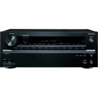
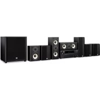
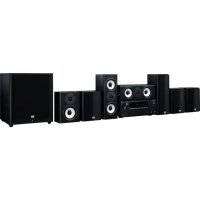
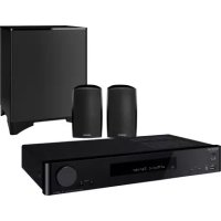
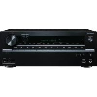
- 5.1ch Home Theater System
- HT-S3100
- HT-S3105
- Instruction Manual
- Contents
- WARNING:
- CAUTION:
- WARNING
- AVIS
- Important Safety Instructions
- Power Warning
- Handling Notes
- For U.S. models
- FCC Information for User
- NOTE:
- For Canadian Models
- IMPORTANT
- For European Models
- Memory Backup
- Placement
- Using Close to a TV or Computer
- Input Signal Warning
- HT-R340 AV Receiver
- HTP-360 Speaker Package (North American and Asian model)
- SKF-360F L/R 2-Way Front Speakers SKC-360C 2-Way Center Speaker (North American model)
- SKC-360C 2-Way Center Speaker (Asian model)
- SKM-360S L/R Full-Range Surround Speakers
- SKW-360 Bass Reflex Subwoofer
- HTP-318 Speaker Package (European model)
- SKF-318FL/R 2-Way Front Speakers SKC-318C 2-Way Center Speaker
- SKM-318S L/R Full-Range Surround Speakers
- SKW-318 Bass Reflex Subwoofer
- Introduction
- Connection
- Turning On & First Time Setup
- Basic Operation
- Enjoying the Listening Modes
- Advanced Operation
- Troubleshooting. 58
- Specifications 62
- Package Contents
- AV Receiver HT-R340
- Indoor FM antenna
- Power-plug adapter
- Speaker Package HTP-360 (North American and Asian models)
- Speaker Package HTP-318 (European models)
- Speaker Package Accessories
- Front Panel
- ① STANDBY/ON button (37)
- ② STANDBY indicator (37)
- ③ Remote-control sensor (19)
- ④ STEREO button (49)
- ⑤ LISTENING MODE [<]/[▶] buttons (49)
- ⑥ Display
- ⑦ DISPLAY button (40)
- ⑧ DIGITAL INPUT button (38, 57)
- DIMMER or RT/PTY/TP button (44, 45)
- Display
- Rear Panel
- Rear
- ① Speaker terminals
- ② Keyhole slots
- ③ Speaker mount/bracket inserts
- How to Use the Remote Controller
- RECEIVER/TAPE Mode
- DVD, CD, MD, CDR & HDD Modes
- Use the REMOTE MODE buttons to select a mode.
- Use the buttons supported by that mode to control the component.
- RECEIVER Mode
- STEREO button
- SURROUND button
- DVD Mode
- CD Mode
- MD, & CDR Mode
- To select your MiniDisc or CD recorder as the input source, press:
- ① ON/STANDBY button
- ② Number buttons
- ③ Playback buttons
- ④ DISPLAY button
- ⑤ CLR button
- ⑥ RANDOM button
- ⑦ REPEAT button
- ⑧ PLAY MODE button
- HDD Mode
- TAPE Mode
- Setting the Voltage Selector (on some models)
- Installing the Batteries
- Notes:
- Using the Remote Controller
- Speaker Sets A and B
- Speaker Set A: Main Room
- Center speaker (SKC-360C)
- Front left and right speakers (SKF-360F L/R)
- Subwoofer (SKW-360)
- Surround left and right speakers (SKM-360S L/R)
- Speaker Connection Precautions
- Connecting Speaker
- Wall Mounting
- Using Speaker Mounts/Brackets
- Using the Rubber Stoppers for a More Stable Platform
- Using the Floor Pads for Subwoofer
- Connecting the Indoor FM Antenna
- Attach the FM antenna, as shown.
- American Model
- Other Models
- Fully extend the antenna and point it in various directions to find the best reception. Secure it in that position with thumb-tacks or something similar.
- Connecting the AM Loop Antenna
- Assemble the AM loop antenna, inserting the tabs into the base, as shown.
- Connect both wires of the AM loop antenna to the AM push terminals, as shown.
- Connecting an Outdoor FM Antenna
- Using a TV/FM Antenna Splitter
- Connecting an Outdoor AM Antenna
- About AV Connections
- Optical Digital Jacks
- AV Connection Color Coding
- AV Cables & Jacks
- Connecting Both Audio & Video
- Which Connections Should I Use?
- Video Connection Formats
- Audio Connection Formats
- Connecting a DVD Player
- Step 1: Video Connection (DVD Player to AV Receiver to TV)
- Step 2: Audio Connection
- —Multichannel Audio Connection—
- Connecting a VCR
- Connecting a VCR for Playback
- Step 1: Video Connection (VCR to AV Receiver to TV)
- Connecting a VCR for Recording
- Step 1: Video Connection
- Connecting a Camcorder, Games Console, or Other Device
- Connecting a Satellite, Cable, Set-top Box, or Other Video Source
- Connecting a CD Player or Turntable
- CD Player or Turntable with Built-in Phono Preamp
- Turntable (MM) with no Phono Preamp Built-in
- Turntable with an MC (Moving Coil) Cartridge
- Connecting an Onkyo RI Dock for the iPod
- If Your iPod Supports Video:
- If Your iPod Doesn't Support Video:
- Connecting a Cassette, CDR, MiniDisc, or DAT Recorder
- Connecting Onkyo R1 Components
- Auto Power On/Standby
- Direct Change
- Remote Control
- Connecting the Power Cord
- Turning On the AV Receiver
- Press the [STANDBY/ON] button.
- Alternatively, press the remote controller's [RECEIVER] button followed by the [ON/STANDBY] button.
- Smooth Operation in a Few Easy Steps
- Have you connected a component to a digital audio input?
- Have you connected an Onkyo MD recorder, CD recorder, or RI Dock?
- Testing the speakers
- Assigning Digital Inputs to Input Sources
- Changing the Input Display
- Basic AV Receiver Operation
- Using the Multichannel Input
- Press the [RECEIVER] button followed by the [MULTI CH] button so that MULTI CH indicator appears on the display.
- Displaying Source Information
- Interpreting Surround Channel Information
- Listening to the Radio
- AM Frequency Step Setup (not North America and Europe)
- Tuning into Radio Stations
- Auto Tuning Mode
- Manual Tuning Mode
- Tuning into weak FM stereo stations
- Presetting Radio Stations
- Selecting Preset Stations
- Deleting Presets
- Displaying Radio Information
- Using RDS (European models only)
- What is RDS?
- PS (Program Service)
- RT (Radio Text)
- PTY (Program Type)
- TP (Traffic Program)
- Displaying Radio Text (RT)
- Press the [RT/PTY/TP] button once.
- Finding Stations by Type (PTY)
- Use the [TUNER] input selector button to select FM.
- Press the [RT/PTY/TP] button twice.
- Use the PRESET [] / [] buttons to select the type of program you want.
- To start the search, press [ENTER].
- When a station you want to listen to is found, press [ENTER].
- Listening to Traffic News (TP)
- Press the [RT/PTY/TP] button three times.
- To locate a station that is broadcasting TP, press [ENTER].
- Using Headphones
- Setting the Display Brightness
- Adjusting the Bass & Treble
- Bass
- Treble
- Muting the AV Receiver
- Using the Sleep Timer
- Using the OptiResponse Equalizer
- Adjusting Speaker Levels
- Speaker Set B
- Headphones
- Multichannel DVD Input
- Recording the Input Source
- Recording from Different AV Sources
- Selecting Listening Modes
- [STEREO] button
- [SURROUND] button (remote controller only)
- LISTENING MODE [<] buttons
- About the Listening Modes
- Direct
- Stereo
- Mono
- Dolby Pro Logic II Movie
- Dolby Pro Logic II Music
- Dolby Pro Logic II Game
- Dolby Digital
- DTS
- Neo:6
- Onkyo Original DSP Modes
- Mono Movie
- Orchestra
- Unplugged
- Studio-Mix
- TV Logic
- All Ch Stereo
- Full Mono
- Using the Audio Adjust Functions
- Input Channel Settings
- Multiplex
- Mono (2ch)
- PLII Music Mode Settings
- Panorama
- Dimension
- Center Width
- DTS Neo:6 Music Mode Setting
- Center Image
- Using the Late Night Function (Dolby Digital only)
- Press the [RECEIVER] button, and then press the [L NIGHT] button repeatedly to select:
- Using the CinemaFILTER
- Press the [RECEIVER] button, and then press the [CINE FLTR] button repeatedly to select:
- Speaker Distance
- Speaker Levels
- Speaker Configuration
- Crossover Frequency
- Use the Down [▼] button to select "Crossover," and then use the Left and Right [▲]/[▶] buttons to select a crossover frequency.
- Double Bass
- Use the Down [▼] button to select "Double Bass," and then use the Left and Right [▲]/[▶] buttons to select:
- Press the [SETUP] button.
- Digital Input Signal Formats
- Press and hold the AV receiver's [DIGITAL INPUT] button for about 3 seconds.
- While "Auto" is displayed (about 3 seconds), press the [DIGITAL INPUT] button again to select: PCM, DTS, or Auto.
- Correcting Sound and Picture Sync
- Power
- Can't turn on the AV receiver?
- The AV receiver turns off as soon as it's turned on?
- Audio
- There's no sound or it's very quiet?
- Only the front speakers produce sound?
- Only the center speaker produces sound?
- The surround speakers produce no sound?
- The center speaker produces no sound?
- The subwoofer produces no sound?
- There's no sound with a certain signal format?
- Can't get 5.1-channel playback?
- The volume cannot be set to 79?
- Noise can be heard?
- The Late Night function doesn't work?
- The DVD analog multichannel input doesn't work?
- About DTS signals
- Video
- There's no picture?
- Tuner
- Reception is noisy, stereo FM reception suffers from hiss, or the FM STEREO indicator doesn't appear?
- Remote Controller
- The remote controller doesn't work?
- Can't control other components?
- RI Dock for the iPod
- There's no sound
- There's no video
- The AV receiver's remote controller doesn't control your iPod
- The AV receiver unexpectedly selects your iPod as the input source
- Recording
- Can't record?
- Others
- The sound changes when I connect my headphones?
- How do I change the language of a multiplex source?
- The RI functions don't work?
- 5.1ch Home Theater Speaker Package
- Passive Subwoofer (SKW-360/SKW-318)
- ■ Front Speaker (SKF-360F)
- ■ Front Speaker (SKF-318F)
- Center Speaker (SKC-360C/SKC-318C)
- Surround Speaker (SKM-360S)
- Surround Speaker (SKM-318S)
- ONKYO CORPORATION
- ONKYO EUROPE ELECTRONICS GmbH
- ONKYO EUROPE UK Office
- ONKYO CHINA LIMITED
Brand : ONKYO
Model : HT-S3105
Category : Home theater audio system