
HT-S670 - Home theater audio system ONKYO - Free user manual and instructions
Find the device manual for free HT-S670 ONKYO in PDF.

| Product Type | 5.1-channel home cinema audio system |
| Brand | ONKYO |
| Model | HT-S670 |
| Amplifier | Built-in, 100 W per channel (6 ohms, 1 kHz, 1% THD) |
| Supported audio formats | Dolby TrueHD, DTS-HD Master Audio, Dolby Digital Plus |
| HDMI inputs | 4 inputs, 1 output |
| Optical inputs | 2 |
| Coaxial inputs | 1 |
| Subwoofer output | 1 (pre-out) |
| Network connectivity | Ethernet, built-in Wi-Fi |
| Bluetooth | Yes, version 4.1 |
| FM/AM radio | FM with RDS |
| Dimensions (W x H x D) | 435 x 173 x 328 mm |
| Weight | Approximately 9.5 kg |
| Power supply | 220-240 V ~ 50/60 Hz |
| Power consumption | 550 W (standby: 0.1 W) |
| Acoustic calibration | AccuEQ |
| Maintenance and cleaning | Wipe with a dry, soft cloth. Do not use any solvents. |
| Safety | Do not expose to moisture. Disconnect before cleaning. |
| Spare parts and repairability | Contact an authorized ONKYO service center. Repairability index: 7.5/10. |
Frequently Asked Questions - HT-S670 ONKYO
User questions about HT-S670 ONKYO
0 question about this device. Answer the ones you know or ask your own.
Ask a new question about this device
Download the instructions for your Home theater audio system in PDF format for free! Find your manual HT-S670 - ONKYO and take your electronic device back in hand. On this page are published all the documents necessary for the use of your device. HT-S670 by ONKYO.
USER MANUAL HT-S670 ONKYO
Thank you for purchasing an Onkyo AV Receiver. Please read this manual thoroughly before making connections and plugging in the unit. Following the instructions in this manual will enable you to obtain optimum performance and listening enjoyment from your new AV Receiver. Please retain this manual for future reference.
Contents
Before using
Important safeguards 2
Precautions 3
Features 4
Supplied accessories 4
Before using the HT-R420 5
Facilities and connections
Index to parts and controls 6
Connecting to audio/video equipment 10
Positioning speakers/Connecting speakers ... 12
Connecting antennas. 14
Connections for remote control (RI) 16
Enjoying music or videos
Enjoying music or videos with the HT-R420 17
Speaker setup 18
Changing the default settings according to your connections 21
Listening to the radio 22
Various functions common to all the sources..24
Enjoying multi channel sources 27
Enjoying the listening modes 28
Audio adjust function 30
Recording a source 32
Remote controller
Using the remote controller with your other AV components 33
Appendix
Troubleshooting 38
Specifications back cover page
WARNING:
TO REDUCE THE RISK OF FIRE OR ELECTRIC SHOCK, DO NOT EXPOSE THIS APPARATUS TO RAIN OR MOISTURE.
CAUTION:
TO REDUCE THE RISK OF ELECTRIC SHOCK, DO NOT REMOVE COVER (OR BACK). NO USER-SERVICEABLE PARTS INSIDE. REFER SERVICING TO QUALIFIED SERVICE PERSONNEL.

WARNING
RISK OF ELECTRIC SHOCK
DO NOT OPEN
AVIS
RISQUE DE CHOC ELECTRIQUE
NE PAS OUVBIR

The lightning flash with arrowhead symbol, within an equilateral triangle, is intended to alert the user to the presence of uninsulated "dangerous voltage" within the product's enclosure that may be of sufficient magnitude to constitute a risk of electric shock to persons.

The exclamation point within an equilateral triangle is intended to alert the user to the presence of important operating and maintenance (servicing) instructions in the literature accompanying the appliance.
Important Safety Instructions
-
Read these instructions.
-
Keep these instructions.
-
Heed all warnings.
-
Follow all instructions.
-
Do not use this apparatus near water.
-
Clean only with dry cloth.
-
Do not block any ventilation openings. Install in accordance with the manufacturer's instructions.
-
Do not install near any heat sources such as radiators, heat registers, stoves, or other apparatus (including amplifiers) that produce heat.
-
Do not defeat the safety purpose of the polarized or grounding-type plug. A polarized plug has two blades with one wider than the other. A grounding type plug has two blades and a third grounding prong. The wide blade or the third prong are provided for your safety. If the provided plug does not fit into your outlet, consult an electrician for replacement of the obsolete outlet.
-
Protect the power cord from being walked on or pinched particularly at plugs, convenience receptacles, and the point where they exit from the apparatus.
-
Only use attachments/accessories specified by the manufacturer.
-
Use only with the cart, stand, tripod, bracket, or table specified by the manufacturer, or sold with the apparatus. When a cart is used, use caution when moving the cart/ apparatus combination to avoid injury from tip-over.
PORTABLE CART WARNING

S3125A
-
Unplug this apparatus during lightning storms or when unused for long periods of time.
-
Refer all servicing to qualified service personnel. Servicing is required when the apparatus has been damaged in any way, such as power-supply cord or plug is damaged, liquid has been spilled or objects have fallen into the apparatus, the apparatus has been exposed to rain or moisture, does not operate normally, or has been dropped.
-
Damage Requiring Service
Unplug the apparatus from the wall outlet and refer servicing to qualified service personnel under the following conditions:
A. When the power-supply cord or plug is damaged,
B. If liquid has been spilled, or objects have fallen into the apparatus,
C. If the apparatus has been exposed to rain or water,
D. If the apparatus does not operate normally by following the operating instructions. Adjust only those controls that are covered by the operating instructions as an improper adjustment of other controls may result in damage and will often require extensive work by a qualified technician to restore the apparatus to its normal operation,
E. If the apparatus has been dropped or damaged in any way, and
F. When the apparatus exhibits a distinct change in performance this indicates a need for service.
- Object and Liquid Entry
Never push objects of any kind into the apparatus through openings as they may touch dangerous voltage points or short-out parts that could result in a fire or electric shock.
The apparatus shall not be exposed to dripping or splashing and no objects filled with liquids, such as vases shall be placed on the apparatus.
Don't put candles or other burning objects on top of this unit.
- Batteries
Always consider the environmental issues and follow local regulations when disposing of batteries.
- If you install the apparatus in a built-in installation, such as a bookcase or rack, ensure that there is adequate ventilation.
Leave 20cm (8") of free space at the top and sides and 10cm (4") at the rear. The rear edge of the shelf or board above the apparatus shall be set 10cm (4") away from the rear panel or wall, creating a flue-like gap for warm air to escape.
Precautions
For U.S. models
Note to CATV system installer:
This reminder is provided to call the CATV system installer's attention to Section 820-40 of the NEC which provides guidelines for proper grounding and, in particular, specifies that the cable ground shall be connected to the grounding system of the building, as close to the point of cable entry as practical.
FCC information for user
CAUTION:
The user changes or modifications not expressly approved by the party responsible for compliance could void the user's authority to operate the equipment.
NOTE:
This equipment has been tested and found to comply with the limits for a Class B digital device, pursuant to Part 15 of the FCC Rules. These limits are designed to provide reasonable protection against harmful interference in a residential installation. This equipment generates, uses and can radiate radio frequency energy and, if not installed and used in accordance with the instructions, may cause harmful interference to radio communications. However, there is no guarantee that interference will not occur in a particular installation.
If this equipment does cause harmful interference to radio or television reception, which can be determined by turning the equipment off and on, the user is encouraged to try to correct the interference by one or more of the following measures:
- Reorient or relocate the receiving antenna.
- Increase the separation between the equipment and receiver.
- Connect the equipment into an outlet on a circuit different from that to which the receiver is connected.
- Consult the dealer or an experienced radio/TV technician for help.
For Canadian models
NOTE: THIS CLASS B DIGITAL APPARATUS COMPLIES WITH CANADIAN ICES-003.
For models having a power cord with a polarized plug:
CAUTION: TO PREVENT ELECTRIC SHOCK, MATCH WIDE BLADE OF PLUG TO WIDE SLOT, FULLY INSERT.
- Recording Copyright—Unless it's for personal use only, recording copyrighted material is illegal without permission of the copyright holder.
- AC Fuse—The AC fuse inside the HT-R420 is not user-serviceable. If you cannot turn on the HT-R420, contact your Onkyo dealer.
- Care—Occasionally you should dust the HT-R420 all over with a soft cloth. For stubborn stains, use a soft cloth dampened with a weak solution of mild detergent and water. Dry the HT-R420 immediately afterwards with a clean cloth. Don't use abrasive cloths, thinners, alcohol, or other chemical solvents, because they may damage the finish or remove the panel lettering.
4. Power
WARNING
BEFORE PLugging IN THE UNIT FOR THE FIRST TIME, READ THE FOLLOWING SECTION CAREFULLY.
AC outlet voltages vary from country to country. Make sure that the voltage in your area meets the voltage requirements printed on the HT-R420's rear panel (e.g., AC 230 V, 50 Hz or AC 120 V, 60 Hz).
The Worldwide model has a voltage selector for compatibility with power systems around the world. Before you plug in this model, make sure that the voltage selector is set to the correct voltage for your area.
Setting the [STANDBY/ON] switch to STANDBY does not fully shutdown the HT-R420. If you do not intend to use the HT-R420 for an extended period, remove the power cord from the AC outlet.
Features
Amplifier Features
- 5 × 100 ~W / Channel @ 8, 20 - 20 kHz, 0.08 % THD
- WRAT-Wide Range Amplifier Technology
- Optimum Gain Volume Circuitry
- DTS, Dolby Digital, Dolby Pro Logic II
- CinemaFILTER
Non-Scaling Configuration
A-Form-Auto Format Sensing - Linear PCM 96 kHz/24-bit D/A Converters
- Advanced 24-bit DSP Chips
3 S-Video Inputs/1 Output
2 Digital Inputs (Optical/Coaxial) - Subwoofer Pre Out
Dot Matrix FL Display
Crossover Adjustment (60/80/100/120/150 Hz)
Color-Coded Speaker Posts
FM/AM Tuner Features
30 FM/AM random presets
FM auto tuning
FM indoor antenna supplied
- AM indoor antenna supplied
- Manufactured under license from Dolby Laboratories. "Dolby", "Pro Logic" and the double-D symbol are trademarks of Dolby Laboratories.
**“DTS” and “DTS Digital Surround” are registered trademarks of Digital Theater Systems, Inc.
Supplied accessories
Check that the following accessories are supplied with the HT-R420.
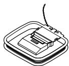
AM loop antenna × 1

FM indoor antenna × 1 (Connect type varies from country to country.)
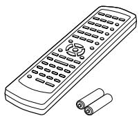
Remote controller × 1
America.....RC-518M
Others..... RC-479S
Batteries (AA/R6) × 2
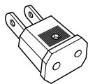
Power-plug adapter
Only supplied in certain countries. Use this adapter if your AC outlet does not match with the plug on the HT-R420's power cord. (Adapter varies from country to country.)
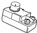
75/300-ohm antenna adapter
Not supplied with American model.)
The alphabet displayed at the end of the product name found in catalogs and on the packages represents the color of this receiver. Though the color varies, the specifications and operations are the same.
Before Using the HT-R420
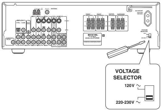
Setting the Voltage Selector (Worldwide model only)
The Worldwide model has a voltage selector for compatibility with power systems around the world. Before you plug in this model, make sure that the voltage selector is set to the correct voltage for your area. If it isn't, use a small screwdriver to set it as appropriate. For example, if the voltage in your area is 120 volts (V), set the selector to "120V." And if it's between 220 and 230 volts (V), set it to "220-230V."
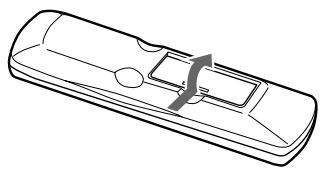
Installing the Batteries
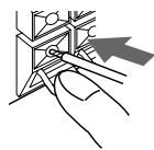
1 Open the battery compartment, as shown.
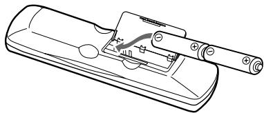
2 Insert the two supplied batteries (AA/R6) in accordance with the polarity diagram inside the battery compartment.
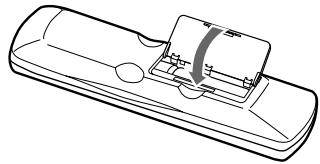
3 Close the battery compartment.
Notes
- The supplied batteries should last for about six months, although this will vary with usage.
- If the remote controller doesn't work reliably, try replacing both batteries.
- Don't mix new and old batteries, or different types of batteries.
- If you intend not to use the remote controller for a long time, remove the batteries to prevent possible leakage and corrosion.
- Flat batteries should be removed as soon as possible to prevent possible leakage and corrosion.
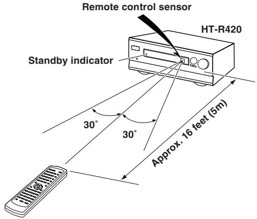
Using the Remote Controller
To use the remote controller, point it at the HT-R420's remote control sensor, as shown below. The HT-R420's STANDBY indicator flashes while a signal is being received from the remote controller.
Notes
- The remote controller may not work reliably if the HT-R420 is subjected to bright light, such as direct sunlight or inverter-type fluorescent lights. Keep this in mind when installing the HT-R420.
- If another remote controller of the same type is used in the same room, or the HT-R420 is installed close to equipment that uses infrared rays, the remote controller may not work reliably.
- Don't put anything, such as a book, on the remote controller, because the buttons may be pressed inadvertently, thereby draining the batteries.
- The remote controller may not work reliably if the HT-R420 is installed in a rack behind colored glass doors. Keep this in mind when installing the HT-R420.
- The remote controller will not work if there's an obstacle between it and the HT-R420's remote control sensor.
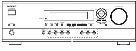
Index to parts and controls
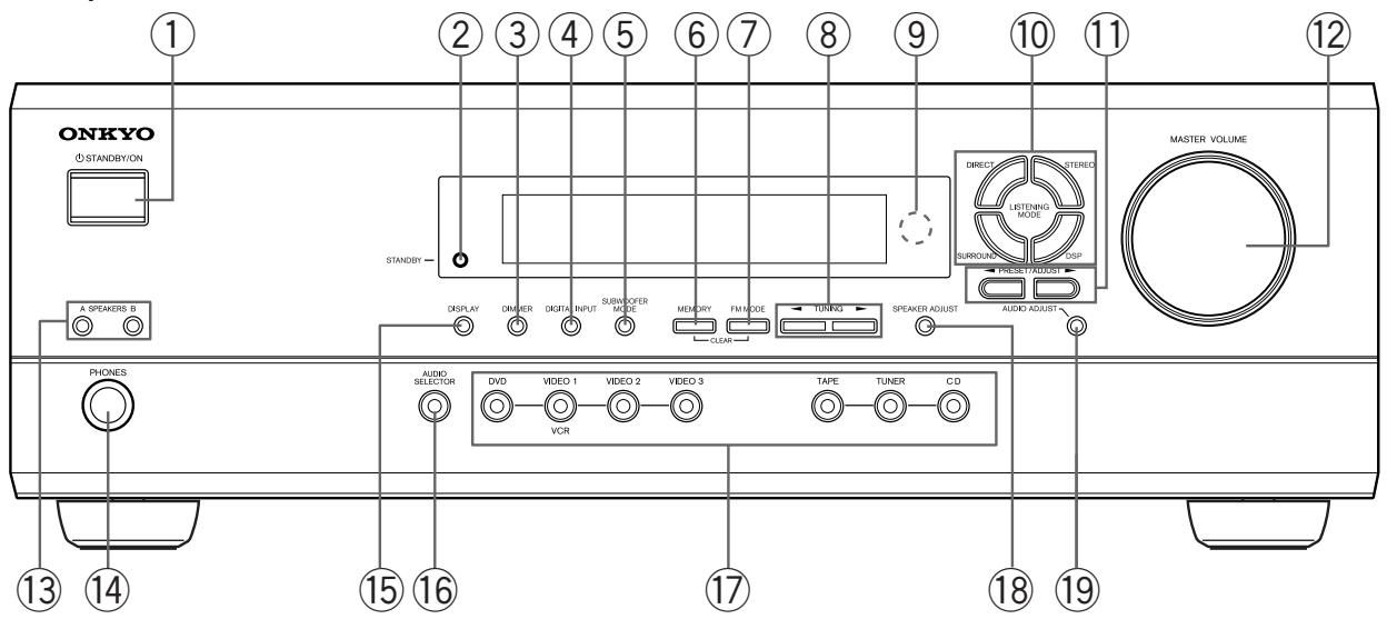
Front panel
For operational instructions, refer to the page indicated in brackets.
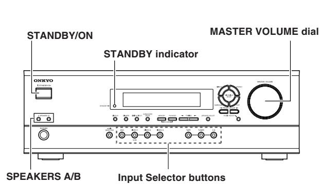
① STANDBY/ON button [17]
When STANDBY/ON button is pressed to ON, the display will light to show the current volume setting for about 5 seconds then show the current sound input source. Pressing the button again returns the HT-R420 to the standby state. This state turns off the display, disables control functions.
(2) STANDBY indicator [17]
Lights when the HT-R420 is in the standby state and flashes when a signal is received from the remote controller.
DIMMER button [25]
Press to set the brightness of the front display. The brightness changes to normal, dim and very dim.
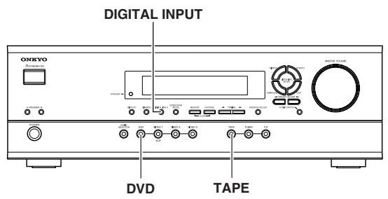
④ DIGITAL INPUT button [21]
When digital components are connected to the DIGITAL INPUT jacks of the HT-R420, use this button to assign the DIGITAL INPUT jacks to them according to their forms of connection.
SUBWOOFER MODE button [20]
Press to select the subwoofer mode.
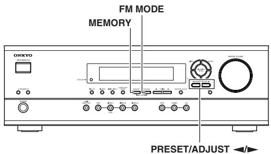
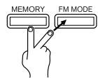
(6) MEMORY button [23]
This button is used to assign the radio station that is currently tuned in to a preset channel or delete a previously preset station.
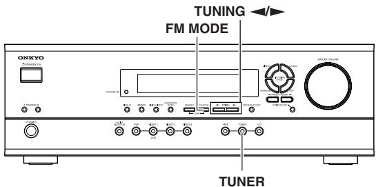
⑦ FM MODE button [22, 23]
Press to switch the reception mode between stereo and monaural. If audio is interrupted or noise interferes with audio during FM stereo broadcasting, press this button to switch to the monaural reception mode.
8 TUNING buttons [22]
Use these buttons to change the tuner frequency.
When FM is selected, you can hold down one of the TUNING buttons and then release it to activate the auto-search feature. It will search for a station in the direction of the button you pressed and stop when it tunes into one.
Remote control sensor [5]
This sensor receives the control signals from the remote controller.
10 LISTENING MODE buttons [27, 29]
Press these buttons to select a listening mode for the current source. Press the DSP button to recall the Onkyo-original DSP modes in sequence. Press the DIRECT, STEREO or SURROUND button to recall the corresponding listening mode directly.
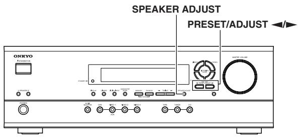
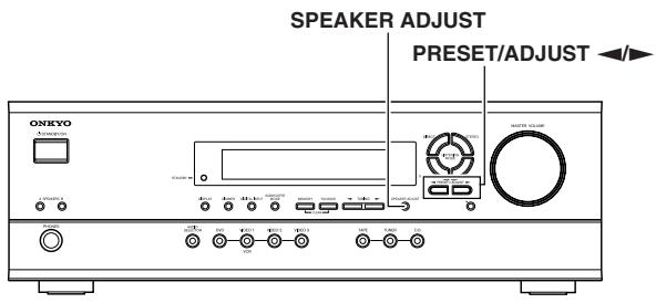
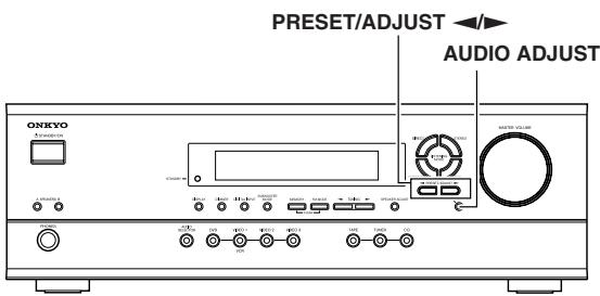
11 PRESET/ADJUST buttons [18, 19, 23, 30]
These buttons make it possible to store desired radio stations under the desired preset numbers and recall them with an easy operation. Also, these buttons adjust the values and parameters of the mode selected using the AUDIO ADJUST, SPEAKER ADJUST or AUDIO SELECTOR button.
12 MASTER VOLUME dial [17]
The MASTER VOLUME dial is used to control the volume level. Turn the dial clockwise to increase the volume level and counterclockwise to decrease it.
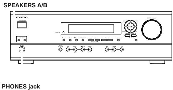
13 SPEAKERS A/B buttons [17, 24]
Press SPEAKERS A/B to turn on/off the speaker system A/B. The (SPEAKERS) A/B indicators corresponding to the selected speaker system light up. You can use SPEAKERS A and B simultaneously.
14 PHONES jack [24]
This is a standard stereo jack for connecting stereo headphones. The audio for the front right and left speakers are sent to the headphone speakers.
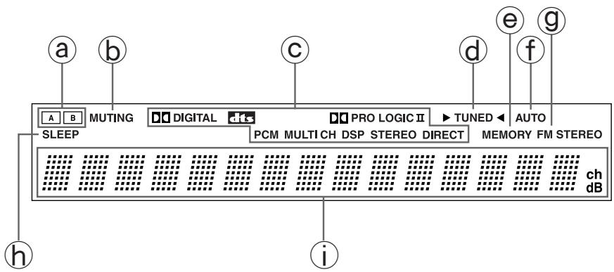
Index to parts and controls
Display
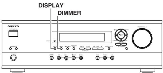
15 DISPLAY button [25]
Each time you press the DISPLAY button, the display changes.
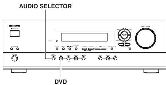
16 AUDIO SELECTOR button [26, 27]
Press to select an audio input signal format other than FM and AM. Each time this button is pressed, the setting cycles.
⑰ Input selector buttons (DVD, VIDEO 1, VIDEO 2,VIDEO 3, TAPE, TUNER, and CD) [17, 21-23, 26, 27, 32]
These buttons are used to select the input source. Pressing and holding the TAPE button for about 2 seconds allows the TAPE and MD sources to be switched.
18 SPEAKER ADJUST button [18, 19]
Press to select speaker setting item.
19 AUDIO ADJUST button [30]
Press to adjust bass, treble, late night function, cinema filter, Panorama, Dimension and Center Width function setting.
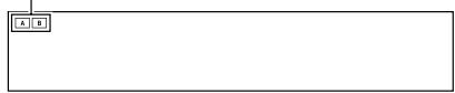
(a) (SPEAKERS) A/B indicators [17, 24]
Shows the current speaker system in use.
b MUTING indicator [24]
Flashes when the mute function is active.
C Source/Listening mode indicators [17, 29]
One of these indicators lights to show the format of the current source as "PCM", "DIGITAL" or "DTS". In addition, one of the listening mode indicators "PRO LOGIC II", "MULTI CH", "DSP", "STEREO" and "DIRECT" lights according to the current listening mode.
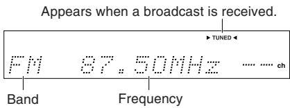
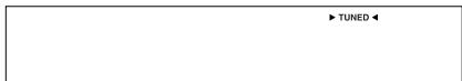
TUNED indicator [22]
Lights up when a radio station is received.
MEMORY indicator [23]
Lights up when the MEMORY button is pressed in the radio station preset operation.
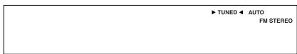
f AUTO indicator [22]
Lights up to indicate auto reception mode (stereo/monaural). At this time, interstation noise will be muted (FM only). It extinguishes when the monaural reception mode is started by pressing the FM MODE button.
G FM STEREO indicator [22]
Lights up when an FM stereo broadcast station is received.
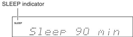
SLEEP indicator [25]
Lights up when the sleep timer is active.
Multi function display
In usual operation, shows the current input source and volume. When the FM or AM input is selected, it shows the frequency and preset number. When the DISPLAY button is pressed, it shows the current input source and the listening mode.
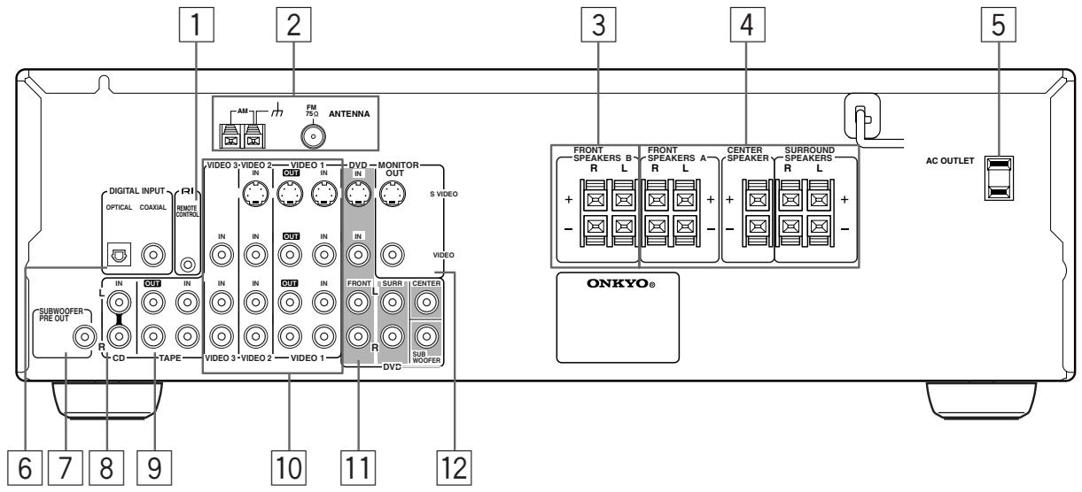
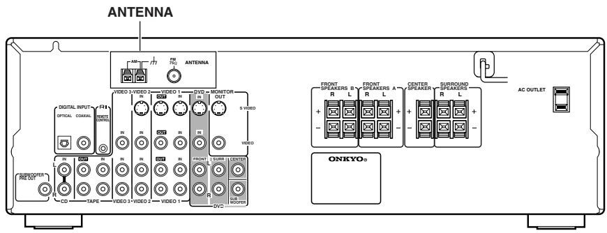
Index to parts and controls
Rear panel
For operational instructions, refer to the page indicated in brackets.
1 RIREMOTECONTROL[16]
Connect the Onkyo components that have RI connectors such as a CD player, and cassette tape deck using the RI cables provided with them. When these components are interconnected, they can be controlled from the remote controller provided with the HT-R420.
For correct operation, the audio connection cables must also be connected. This applies to both remote and standard operation.
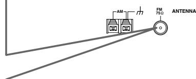
2 ANTENNA [14, 15]
These terminals are for connecting the FM antenna and AM antenna.
These terminals are for connecting the speaker system B.
4 FRONT SPEAKERS A, CENTER SPEAKER and SURROUND SPEAKERS [13]
These terminals are for connecting the speaker system A, including the center and surround speakers.
5 AC OUTLET [11]
The HT-R420 is supplied with AC outlet for connecting the power cord from other devices so that their power is supplied through the HT-R420. By doing this, you can use the STANDBY/ON button on the HT-R420 to turn on and off the connected devices as well.
6 DIGITAL INPUT OPTICAL, COAXIAL [10, 11]
These are digital audio inputs. There is 1 optical jack and 1 coaxial jack. The inputs accept digital audio signals from DVD, LD, CD, or other digital source.
7 SUBWOOFER PRE OUT [13]
This terminal is for connecting an active subwoofer.
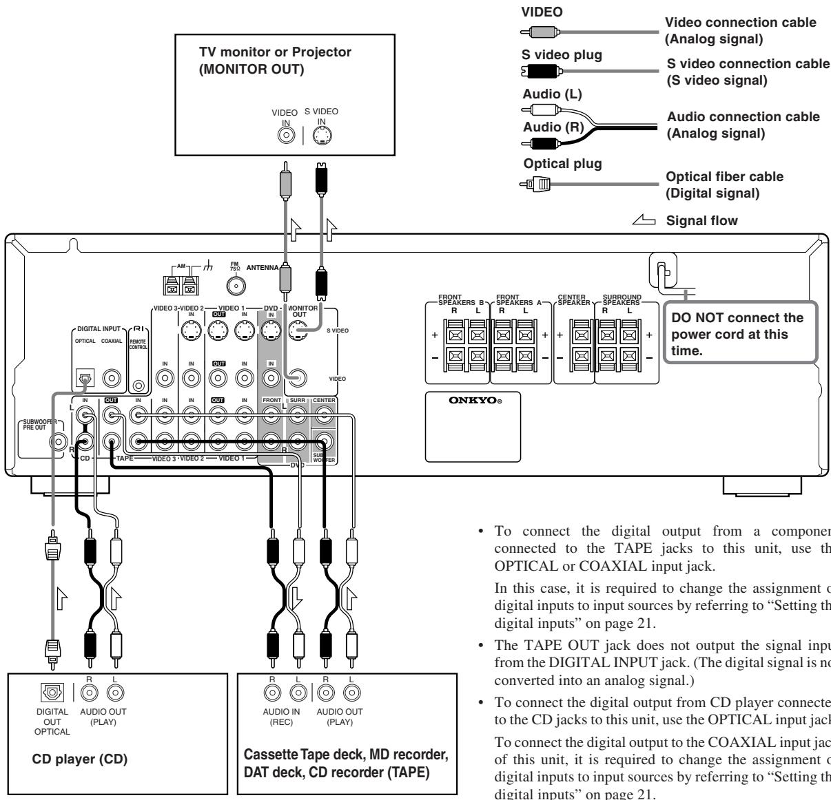
8 CD IN [10]
Connect the output terminal on the CD player to the CD IN L/R jacks on the HT-R420.
9 TAPE IN/OUT [10]
Connect the output terminals (PLAY) of the cassette tape deck or MD recorder to the TAPE IN L/R jacks on the HT-R420 and the input terminals (REC) to the TAPE OUT L/R jacks.
VIDEO 1 IN/OUT,VIDEO 2 IN,VIDEO 3 IN [11]
Connect the output terminals (PLAY) of the video cassette recorder to the VIDEO 1 IN L/R jacks on the HT-R420 and the input terminals (REC) to the VIDEO 1 OUT jacks.
Connect the output terminals of the video cassette player or satellite tuner to the VIDEO 2 IN or VIDEO 3 IN jacks on the HT-R420.
DVD [11]
Connect the DVD player. If the DVD player has 5.1 channel output terminals, connect each terminal to the FRONT L/R, CENTER, SUBWOOFER, and SURR L/R terminals on the HT-R420. If the DVD player has only 2 channel output terminals, connect to the FRONT L/R terminals on the HT-R420.
12 MONITOR OUT [10]
The monitor output includes both RCA type and S video configurations. This output is for connecting television monitors or projectors.
Tip
The audio input jacks of the HT-R420 do not accept direct connection of an analog turnable.
If you want to connect a turntable to the HT-R420 prepare a phono equalizer and connect it to the unused audio input jacks (IN L/R).
Refer to the instruction manuals of the phono equalizer and turntable for details.
Index to parts and controls
Remote controller
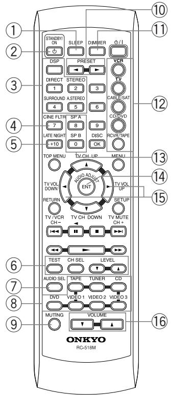
RC-518M (American model)
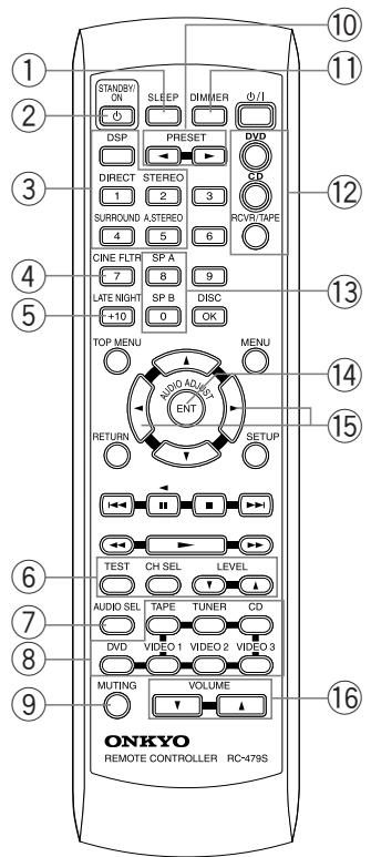
RC-479S (Other models)
Explanations on this page are for controlling the HT-R420. To operate other components, see "Using the remote controller with your other AV components" on pages 33 through 37.
For operational instructions, refer to the page indicated in brackets.
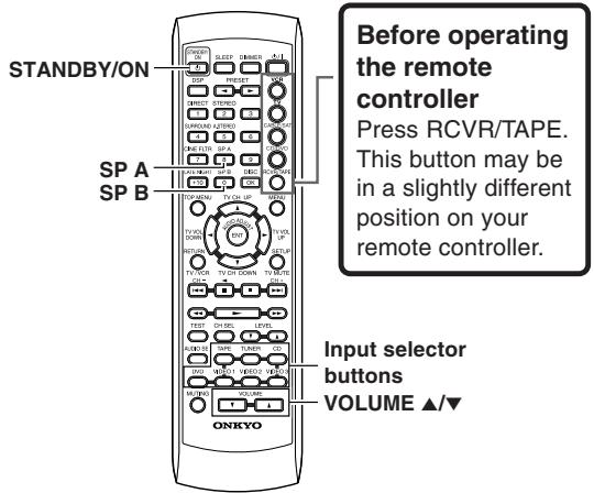
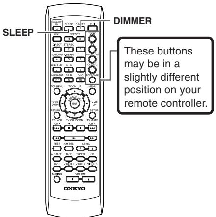
① SLEEP button [25]
For setting the sleep time.
This button is provided only on the remote controller.
(2) STANDBY/ON button [17]
Turns on the HT-R420 or put it in standby.
③ Listening mode buttons [27, 29]
Press to change the listening mode.
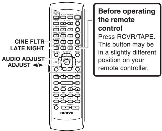
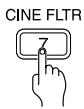
CINE FLTR button [30]
Press to activate/deactivate Cinema Filter function.
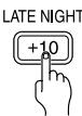
⑤ LATE NIGHT button [30]
Press to change the late night setting.
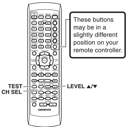
TEST/CH SEL/LEVEL ▲▼ buttons [20, 26]
For setting the output levels for each speaker.
These buttons are provided only on the remote controller.
⑦ AUDIO SEL button [26, 27]
Press to select an audio input signal format.
8 INPUT SELECTOR buttons [17, 21-23, 26, 27, 32]
For selecting the input source.
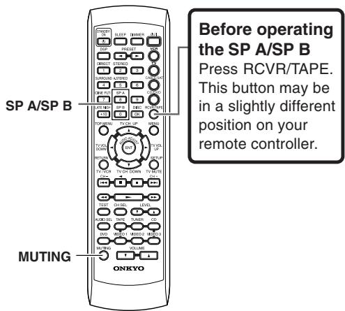
9 MUTING button [24]
Activates the mute function.
This button is provided only on the remote controller.
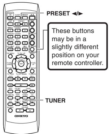
10 PRESET button [23]
For selecting a tuner preset channel.
11 DIMMER button [25]
For adjusting the brightness of the front display.
12 Mode buttons [33-37]
For selecting the component to be operated by the remote controller. The RC-518M remote controller has five mode buttons, the RC-479S has three.
13 SP A/SP B buttons [17, 24]
Press to switch the speaker systems.
14 AUDIO ADJUST button [30]
Press to adjust bass, treble, late night function and cinema filter function setting.
15 ADJUST button [30]
Press to adjust the values and parameters of the mode selected using the AUDIO ADJUST, SPEAKER ADJUST or AUDIO SELECTOR button.
16 VOLUME / button [17]
For adjusting the volume.
Connecting to audio/video equipment
Before connecting
- Be sure to always refer to the instruction manual that came with the component that you are connecting.
- Do not plug in the power cord until all connections have been made.
- For input jacks, red connectors are used for the right channel, white connectors are used for the left channel, and yellow connectors are used for video connection.
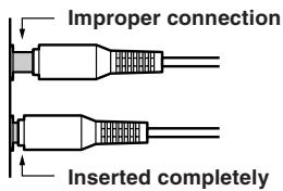
- Insert all plugs and connectors securely. Improper connections can result in noise, poor performance, or damage to the equipment.
- Do not bind audio connection cables with power cords and speaker cables. Doing so may adversely effect the sound quality.
Video Connection Formats
Video equipment can be connected to the HT-R420 using the following video connection formats : Video or S Video, the latter offering the better picture quality.
When choosing a connection format, bear in mind that the HT-R420 doesn't convert between format, so only output connectors of the same format as the input connector will output a signal.
For example, if you connect your DVD player to the SVIDEO DVD IN, a video signal will be output by the SVIDEO MONITOR OUT (for your TV) and the SVIDEO VIDEO 1 OUT (for your VCR), but not the composite video outputs.
Connecting to audio/video equipment
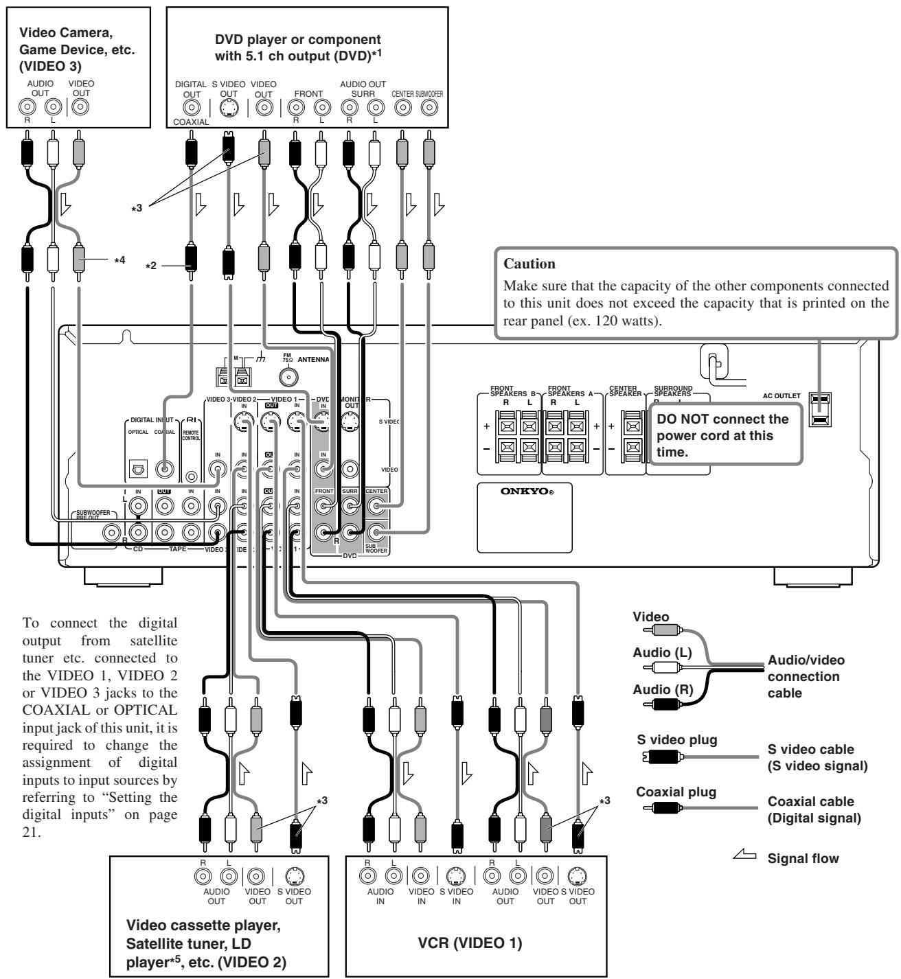
*1 If the DVD player has both 5.1 channel audio outputs and 2 channel audio outputs, and you want to connect the DVD player only using the FRONT L/R jacks on the HT-R420, use the 2 channel audio output jacks on the DVD player. If the DVD player only has the 2 channel audio outputs, connect it to the FRONT L/R jacks.
^2 To connect the digital output from DVD player connected to the DVD jacks to this unit, use the COAXIAL input jack.
To connect the digital output to the OPTICAL input jack of this unit, it is required to change the assignment of digital inputs to input sources by referring to “Setting the digital inputs” on page 21.
*3 Be sure to make the same video connection (either S-VIDEO or standard VIDEO) between your component(s), the receiver, and your TV.
4 VIDEO3 does not have an S VIDEO terminal. Therefore, check that the TV connected to MONITOR OUT is also connected to theVIDEO terminal.
*5 If you have an LD player with AC-3RF output, connect via an AC-3RF demodulator to one of the HT-R420's DIGITAL INPUT terminals.
Positioning speakers/Connecting speakers
Two speaker systems can be connected to the Receiver.
The speaker system A is to be placed in the main room, and the speaker system B is to be placed in a second room.
The speaker system A consists of the FRONT SPEAKERS A (L/R), CENTER SPEAKER, SURROUND SPEAKERS (L/R) and SUBWOOFER.
You can reproduce the sounds such as Dolby surround and DTS surround.
The speaker system B consists of the FRONT SPEAKERS B.
You can reproduce only monaural and stereo sounds.
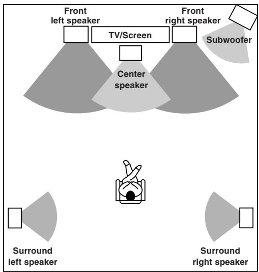
Standard speaker placement of the speaker system A
Speaker placement plays an important role in the reproduction of Surround sound.
The placement of the speakers varies depending on the size of the room and the wall coverings used in the room. The illustration below shows an example of a layout for standard speaker placement. Refer to this example when you position the speakers in order to experience the best of Surround sound.
For ideal Surround effects, all speakers should be installed.
If a center speaker or subwoofer is not connected, the sound from the unused channel is properly distributed to the connected speakers in order to reproduce the best Surround sound possible.
Front
The center speaker reproduces a richer sound image by enhancing the perception of the sound's source and movement.
The left, right, and center speakers should face the seated listener and be placed at ear level.
Surround
The surround speakers reproduce the feel of a moving sound while creating the sensation of being in the middle of the action.
Place the left and right surround speakers 3 feet (1 meter) above the listener's ear level and facing toward the sides of the room, making sure that the listener is within the speakers' dispersion angle.
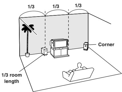
Subwoofer
When bass sound is reproduced, its volume and quality greatly depend on subwoofer placement. Those characteristics also depends on the shape of your listening room as well as your listening point. Generally speaking, good bass sound is obtained when the subwoofer is placed in the corner of the room or at one-third the length of the room.
Refer to the speakers' instruction manuals for details.
Positioning speakers/Connecting speakers
Before connecting
Refer also to the instruction manuals of the speakers.
- Be sure to connect the positive and negative cables for the speakers properly. If they are mixed up, the left and right signals will be reversed and the audio will sound unnatural.
- Connect speakers with an impedance between 8 and 16 Connecting speakers with an impedance less than 8 may damage the HT-R420.
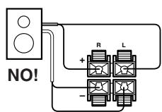
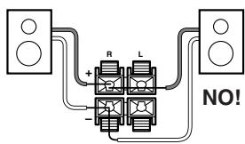
- To prevent damage to circuits, never short-circuit the positive (+) and negative (-) speaker wires.
- Do not connect more than one speaker cable to one speaker terminal. Doing so may damage the HT-R420.
- When you are using only one speaker or when you wish to listen to monaural (mono) sound, a single speaker should never be connected in parallel to both the right and left channel terminals simultaneously.
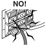
How to connect to the speaker terminals
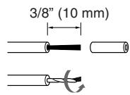
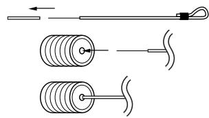
Connecting to the speaker system B Strip 3 / 8" (10 mm) from the end of each cable, then twist the exposed wires tightly.
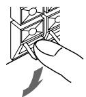
Press and hold the lever.
Insert the stripped end of the cable.
By releasing the lever, the lever is replaced.
Use the SUBWOOFER PRE OUT jack to connect a subwoofer with a built-in power amplifier.
If your subwoofer does not have a built-in amplifier, connect an amplifier to the SUBWOOFER PRE OUT jack and the subwoofer to the amplifier.
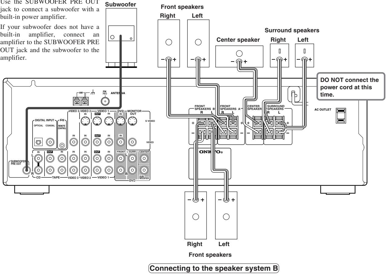
Connecting to the speaker system A
Connecting antennas
Connecting the supplied FM and AM indoor antennas
USA, Canada, Mexico
1 Strip away the insulation from the end of the cord.
2 Fully insert the stripped end of the cord.
Australia
Insert the plug fully into the socket.

Other models
Insert the plug fully into the socket.

Adjusting the position of the FM indoor antenna
The FM indoor antenna is for indoor use only. During use, extend the antenna and move it in various directions until the clearest signal is received. Fix it with push pins or similar implements in the position that will cause the least amount of distortion.
If the reception is not very clear with the attached FM indoor antenna, the use of an outdoor antenna is recommended.
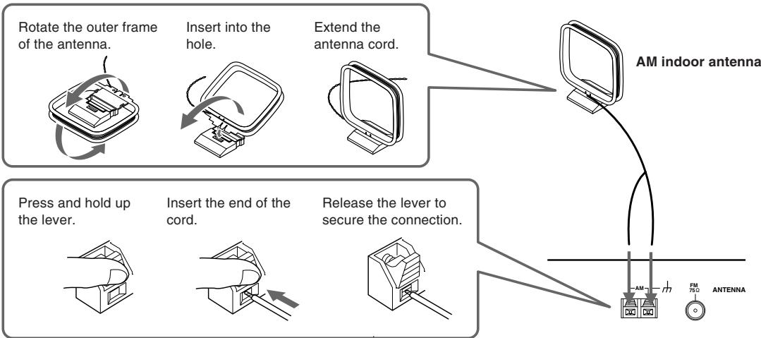
Note
Insert one end of the AM antenna cord to either of the AM antenna connectors and the other end to the other connector. There is no difference between one end of the AM antenna cord and the other end, unlike the speaker cables which have positive and negative poles.
Adjusting the position of the AM indoor antenna
The AM loop antenna is for indoor use only. Set it in the direction and position where you receive signals clearly. Put it as far away as possible from the HT-R420, televisions, speaker cables, and power cords.
When reception is not satisfactory with the attached AM loop antenna alone, connection of an outdoor antenna is recommended.
Connecting antennas
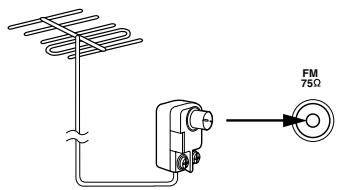
Connecting an Outdoor FM Antenna
If you cannot achieve good reception with the supplied indoor FM antenna, try a commercially available outdoor FM antenna instead.
Notes
- Outdoor FM antennas work best outside, but usable results can sometimes be obtained when installed in an attic or loft.
- For best results, install the outdoor FM antenna well away for tall buildings, preferably with a clear line of sight to your local FM transmitter.
- Outdoor antenna should be located away from possible noise sources, such as neon signs, busy roads, etc.
- For safety reasons, outdoor antenna should be situated well away from power lines and other high-voltage equipment.
- Outdoor antenna must be grounded in accordance with local regulations to prevent electrical shock hazards.
Using the 75/300-ohm Antenna Adapter
The 75/300-ohm Antenna Adapter is not supplied with American and European models.
The 75/300-ohm antenna adapter can be used to connect an FM antenna using either 75-ohm coaxial cable or 300-ohm twin-core flat cable.
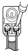
Connecting 300-ohm Flat Cable
-
Using a screwdriver, loosen the two screws on the adapter, wrap the bare wires around the screws, and then retighten them, as shown.
-
Plug the adapter into the 75 socket.
Connecting 75-ohm Coaxial Cable
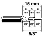
- Strip and prepare the 75 ohm coaxial cable, as shown.
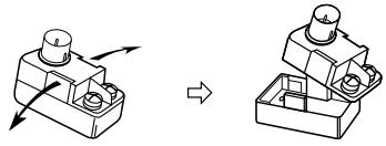
- Using your fingernails or a small screwdriver, lever the adapter's tabs outward and remove the cover, as shown.
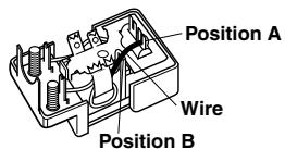
- Move the small wire inside the adapter from position A to position B, as shown.
- Insert the central conductor (①), as shown, and use a small pair of pliers to clamp the shielding and outer insulation sections of the cable (②), as shown.
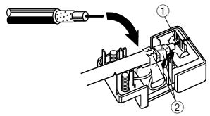
Make sure the shielding is not touching the central conductor.
- Refit the adapter's cover, and then plug the adapter into the 75 socket.
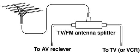
Using a TV/FM Antenna Splitter
It's best not to use the same antenna for both FM and TV reception, as this can cause interference problems. If circumstances demand it, use a TV/FM antenna splitter, as shown.
Connecting an Outdoor AM Antenna
If good reception cannot be achieved using the supplied AM loop antenna, an outdoor AM antenna can be used in addition to the loop antenna, as shown.
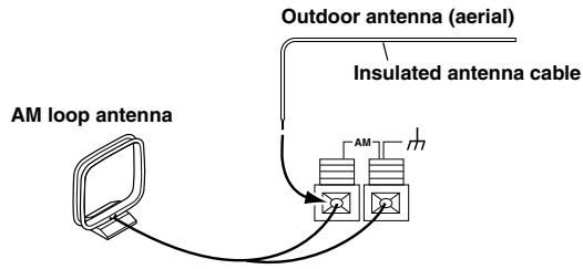
Outdoor AM antennas work best when installed outside horizontally, but good results can sometimes be obtained indoors by mounting horizontally above a window. Note that the AM loop antenna should be left connected.
Outdoor antenna must be grounded in accordance with local regulations to prevent electrical shock hazards.
Connections for remote control (R I)
The RI terminal on the HT-R420 is for connecting other Onkyo components equipped with the same RI terminal. When a component is RI-connected, you can point the remote controller supplied with the HT-R420 at the sensor on the HT-R420 and operate that component without having to switch remote controllers. In addition, by connecting components to the RI terminal, you can also perform the system operation given below.
To connect components using the RI terminal, simply connect a RI cable from this RI terminal to the RI terminal of the other component. An RI cable comes with every cassette tape deck, CD player, and DVD player that has an RI terminal.
Power on/ready function
When the HT-R420 is in the standby state, if an RI-connected component is turned on, then the HT-R420 also turns on and the input source selected at the HT-R420 automatically switches to that component.
If the power cord for an RI-connected component is connected to the AC OUTLET on the HT-R420, or if the HT-R420 is turned on, this function will not work.
Direct change function
When the play button is pressed at an RI-connected component, the input source selected at the HT-R420 automatically changes to that component.
Power off function
When the HT-R420 is placed in the standby state, all RI-connected components are also automatically put in the standby state.
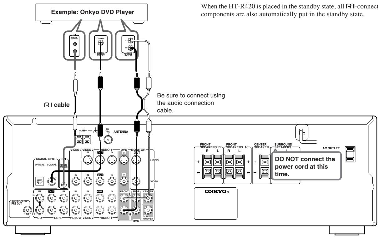
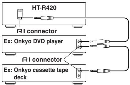
Connection example when there is more than one Onkyo components equipped with RI terminals
Notes
- Connect the plugs securely.
- Be sure to connect to the RI connectors using the RI cable.
- For proper operation the audio connection cables must be connected. This applies to both remote and standard operation.
- If a component has two RI terminals, you can use either one to connect to the HT-R420. The other one can be used to daisy chain with another component.
- With Onkyo DVD players, you can enter the manufacturer code so that you can operate the DVD player directly with the remote controller without connecting the RI terminals (see page 33).
- Do not connect the AV Receiver's RI connector to any component other than an Onkyo product. It may cause malfunction.
- Certain component models may not be able to control the HT-R420.
Enjoying music or videos with the HT-R420
Before connecting
- Make sure that all the connections from pages 10 to 16 are complete.
- Turning on the AV Receiver may cause a momentary power surge, which might interfere with other electrical equipment such as computers. If this happens, use a wall outlet on a different circuit.
Connecting the power
1. Connect the power cord to a wall outlet.
The HT-R420 enters standby mode.
The STANDBY indicator lights up.
2. Press STANDBY/ON.
The AV Receiver turns on.
The display on the AV Receiver's front panel light. At the same time, the STANDBY indicator goes off.
Note
To turn off the AV Receiver, press STANDBY/ON. The AV Receiver enters standby mode. Be sure to set the volume to minimum before turning off the AV receiver.
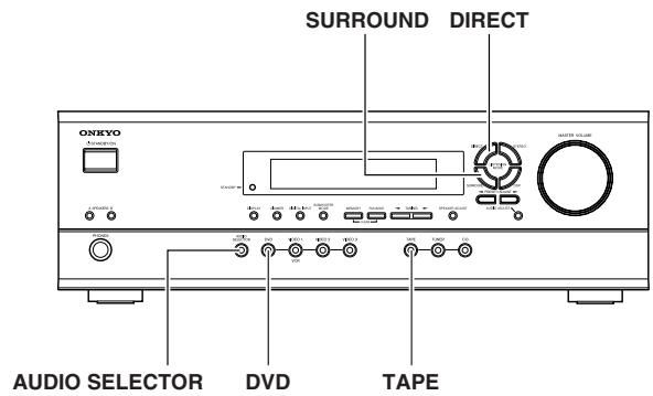
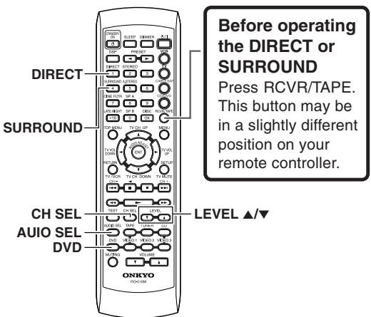
Selecting a source
Before operating the remote controller, press RCVR/TAPE.
1. Press input selector button to select one of the following input sources:
DVD
VIDEO1
VIDEO2
VIDEO3
- TAPE
TUNER
CD
e.g. When VIDEO 3 is selected.
When MD recorder is connected to the TAPE jacks, you can switch the source from TAPE to MD (see page 21).
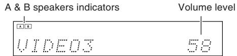
2. Ensure that the A and/or B indicator(s) for the speaker system(s) to be used are lit on the display.
If no indicator is lit, press SPEAKERS A/B on the unit or SP A/SP B on the remote controller to select the speaker system(s) to be used.
3. Start playing the selected source.
See page 22 to listen to the radio.
4. Press VOLUME / on the remote controller or turn MASTER VOLUME dial on the unit to adjust the volume.
The volume can set to Min, 1 through 79, or Max.
About digital sound
If the equipment is digitally connected to the AV Receiver, the sound from the digital input will automatically be selected and reproduced instead of the analog sound as explained below.
The initial settings are as follows:
- When the DVD source is selected, the digital sound from the DIGITAL INPUT COAXIAL connector is reproduced.
- When the CD source is selected, the digital sound from the DIGITAL INPUT OPTICAL connector is reproduced.
See page 21 to change settings.
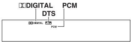
When the digital sound is reproduced, the DIGITAL, DTS, or PCM (2 channel digital stereo) indicator lights up according to the received sound system in the AV Receiver's display.
Speaker setup
You need to set up the speaker configuration for the speaker system A (see page 12).
(There is no speaker configuration setup for the speaker system B.) It is not necessary to set the parameters again once you have completed the setup unless you change the speaker configuration.
Notes
-
Speaker setup cannot be done if;
-
Headphones are connected (see page 24),
- The speaker system B is on (see page 24), or
- "Multi ch" is selected with AUDIO SELECTOR button.
Selecting the number of speaker channels
1. Press SPEAKER ADJUST once.
When the button is pressed, the current speaker setup will be displayed.
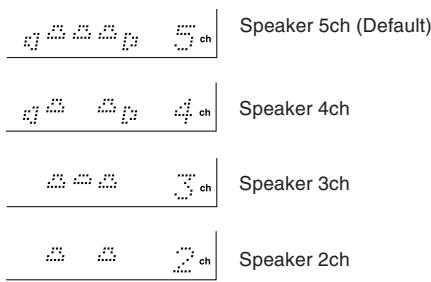
2. Press PRESET/ADJUST repeatedly to select the number of channels.
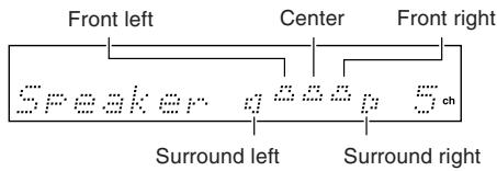
Display and number of speaker channels
Notes
- The listening mode will automatically change according to the number of channels if you set the number of channels.
- Speaker adjust mode will be cancelled if the next operation is not performed within 8 seconds.
Setting the crossover frequency
To reproduce low frequencies between 60Hz and 150Hz in an optimum condition, set the crossover frequency according to the low-frequency reproduction capabilities of the subwoofer and other speakers (front, center and surround).
Home theater in a box
It is not necessary to change this setting when using the supplied speaker system.
If you're not using a subwoofer, bass sounds are output by the other speakers and this setting has no effect.
1. Press SPEAKER ADJUST twice.
The current setting is displayed.
2. Press PRESET/ADJUST repeatedly to select the crossover frequency.
Select from 60, 80, 100, 120 and 150Hz
The following table lists the crossover frequency you should choose depending on the diameter of your front speakers.
| Front speaker diameter | Crossover frequency |
| Larger than 8 inch (20 cm) | 60 Hz |
| 6.4 – 8 inch (16 – 20 cm) | 80 Hz |
| 5.2 – 6.4 inch (13 – 16 cm) | 100 Hz |
| 3.6 – 5.2 inch (9 – 13 cm) | 120 Hz |
| Less than 3.6 inch (9 cm) | 150 Hz |
If you want more accurate setting, refer to the instruction manuals of the speakers and perform the setting according to their frequency response. Also listen to the actual sound and set to the high position (120 or 150Hz ) if you feel that the sound from the subwoofer is not enough or to the low position (60 or 80Hz ) if you feel that the sound is loud.
Specifying speaker distances
To get the best from surround sound, it's important that the sound from each speaker reaches the listener at the same time. To achieve this, you need to specify the distance from each speaker to the listening position.
1. Measure and make a note of the distance from each speaker to the listening position.
2. Press the SPEAKER ADJUST three times.
"Distance Setup" then "Front:" are displayed. Use the DISPLAY button to select meters or feet.
To select other speakers, press SPEAKER ADJUST again.
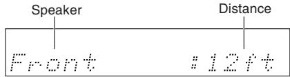
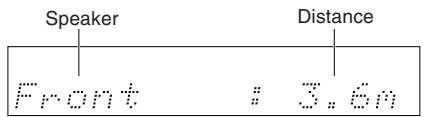
Front
(From Front-left and front-right speakers to your listening position. The default setting is 12 ft (3.6 m).)
↓
Center
(From Center speaker to your listening position. The default setting is 12 ft (3.6m) .)
↓
Surr Right
(From Surround-right speaker to your listening position. The default setting is 7 ft (2.1 m).)
↓
Surr Left
(From Surround-left speaker to your listening position. The default setting is 7 ft (2.1 m).)
↓
Subwoofer
(From Subwoofer to your listening position. The default setting is 12 ft (3.6 m).)
3. Press PRESET/ADJUST repeatedly to specify the speaker distance.
You can specify speaker distances of between 1 and 30 ft. in 1 ft. steps (0.3 and 9m in 0.3m steps). However, the Front Distance limits the Distance of other speakers. The Center Distance and Subwoofer Distance must be within plus or minus 5 ft (1.5m) of the Front Distance. The Surround Right Distance and Surround Left Distance must be no less than -15ft(-4.5m) or no more than +5ft(+1.5m) of the Front Distance. For example, if the Front Distance is set to 20 ft (6m) , you must set the Distance of other speakers as follows: Center Distance, Subwoofer Distance: 15 to 25 ft (4.5 to 7.5m) Surround Right Distance, Surround Left Distance: 5 to 25 ft (1.5 to 7.5m)
4. Repeat steps 2 and 3 for all five parameters.
Speaker setup
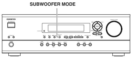
Setting the subwoofer mode
Press SUBWOOFER MODE on the unit.
With the first press of the button, you can check the present setting. Then each press of the button changes the subwoofer mode as follows (a tip on how to select the right subwoofer mode is in parenthesis):
Subwoofer Mode 1 (Default)
(To output the low frequencies of all
channels from the subwoofer.)
↓
Subwoofer Mode 2
Mode2
(To output the low frequencies of the center and surround
channels from the subwoofer.)
↓
Subwoofer Mode 3
Mode3
(To output only the LFE channel* of a 5.1-channel source from
the subwoofer.)
↓
Subwoofer Off
(When no subwoofer is connected or when a subwoofer is connected but not used.)
- LFE channel: The channel recording the LFE (Low Frequency Effects).
The normal display resumes in three seconds.
Note
When the subwoofer mode is set to Mode 2 or Mode 3 and audio is reproduced in the Stereo mode, the subwoofer may not output audio from certain sources (2 channel-Dolby Digital/DTS source etc.).
Adjusting each speaker's relative volume balance — Test tone
Adjust each speaker's relative volume balance so that the volumes of all speakers' test tones sound equal at the listening position. Adjust the volume to your normal listening level, prior to commencing settings.
Note
You cannot adjust the volume balance while the muting function is activated.
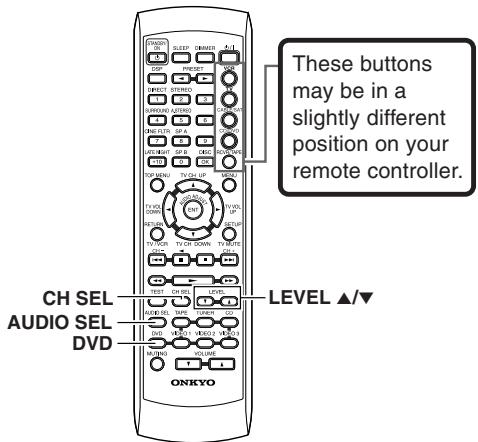
1. Press TEST on the remote controller.
Each speaker emits the test tone (pink noise) and the display shows the speaker emitting the test tone.
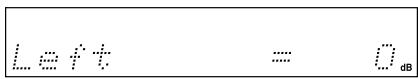
2. Press CH SEL repeatedly to select the speaker, then press LEVEL / on the remote controller to adjust the volume level.
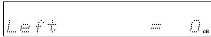
When CH SEL is pressed repeatedly, each speaker produces the test tone (pink noise) in the following order: Left Center Right Surr Right Surr Left Subwoofer.
The volume level can be adjusted between -12dB and +12dB .
Notes
- No test tone will be emitted from the speaker which is not included in the speaker configuration on page 18 even if it is actually connected.
- No test tone will be emitted from the subwoofer when the subwoofer mode is set to "Subwoofer Off".
Even when CH SEL is not pressed, the test tone will move to the next speaker in 2 seconds.
3. When you have completed the adjustment by repeating step 2, press TEST.
The test tone stops and the normal display resumes.
Note
Even if you don't press TEST, the test tone will stop after 2 minutes.
Changing the default settings according to your connections
If equipment couldn't be connected in accordance with the default settings, or your preferred settings differ from the default settings, you can change the settings as described below.
Switch the source from TAPE to MD
You can set the AV receiver to show "MD" when the TAPE source is selected by pressing TAPE on the unit.
1 Press TAPE to select the input source.
2 Press and hold TAPE on the unit until the display changes (for about 2 seconds).
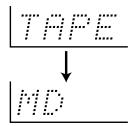
To restore the display
Press and hold TAPE on the unit until the display changes (for about 2 seconds).
Setting the digital inputs
The digital input terminal for each input source is pre-set, as described in the table below. It is necessary to change the settings if the components you connected differ from input source's default settings.
Default setting
| Input source | Digital input |
| CD | OPTICAL |
| TUNER | |
| TAPE | - - - - |
| VIDEO 3 | - - - - |
| VIDEO 2 | - - - - |
| VIDEO 1 | - - - - |
| DVD | COAXIAL |
For example, follow the steps below to assign Optical to the DVD device connected to the DIGITAL INPUT OPTICAL jack.
- Press DVD.
The DVD input is selected and "DVD" appears in the display.
$$ D U D \quad 2 5 $$
- Press DIGITAL INPUT.
The current DVD setting (Coaxial) appears.
$$ D U D \quad + \quad C o a x i \neq 1 $$
- Press DIGITAL INPUT repeatedly to select "Optical".
$$ D U D \neq O F T I C A L $$
Pressing DIGITAL INPUT repeatedly will change the setting as follows:
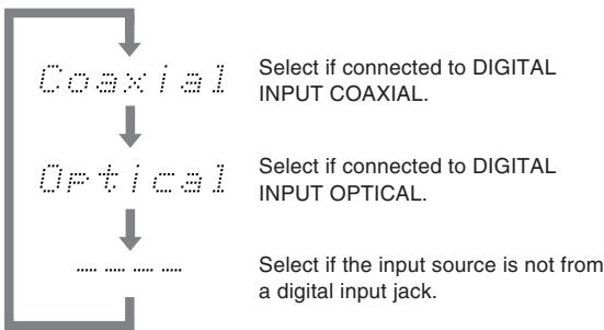
About three seconds after "DVD Optical" is selected, the original display appears and the setting is completed.
If you have selected digital input, you can also select the input signal format (refer to "Setting the input signal format" on page 26).
Listening to the radio
There are two ways to select radio stations:
- Manual tuning
- Presetting radio stations then selecting the preset channels
Tuning into a radio station
1. Press TUNER.
The selected band appears in the display. Each time you press the button, the band changes as follows: AM FM.
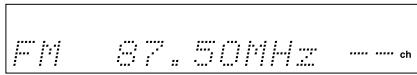
e.g. When FM is selected.
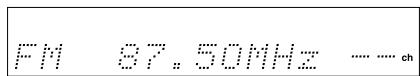
2. Using the TUNING buttons on the front panel, tune into the station you desire.
When you tune into a radio station, TUNED indicator appears in the display. If you tune into an FM station in stereo, then FM STEREO indicator lights up.
- On American models, the tune frequency changes in 100kHz steps for FM and 10kHz steps for AM.
In Australia, the tune frequency changes in 50kHz steps for FM and 9kHz steps for AM.
For countries other than America and Australia, the tune frequency changes in 50kHz steps for FM and 9kHz steps for AM, however the AM tuning step can be set to either 9 kHz or 10kHz . To set it, while holding down the TUNER button, press the MEMORY button.
- When tuning into FM stations, you can press the TUNING buttons continuously for more than 0.5 seconds to scan for an FM station in the direction of the button you pressed (FM auto tuning mode). After you release the button and a station is received in stereo, the scanning stops.
Tuning in a weak frequency (only for FM stations)
When you tune in a stereo FM station, the FM STEREO indicator lights up if the signal is sufficiently strong.
If the signal is weak, you may not be able to tune to the station. In this case, press FM MODE. The FM STEREO indicator and AUTO indicator goes off.
Then select the station to which you want to listen.
(At this time, the station will be in mono and interstation noise will be heard.)
Listening to the radio
Presetting radio stations
You can preset up to 30 stations.
- Tune in the radio station you wish to preset (refer to the previous page).
- Press MEMORY.
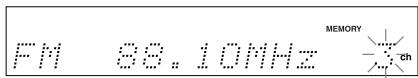
The MEMORY indicator lights and the preset number starts flashing in the display.
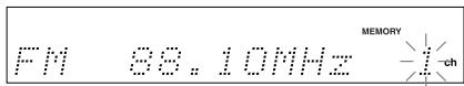
- While the MEMORY indicator is lit (for about 8 seconds), press PRESET/ADJUST to select the preset number.
- Press MEMORY.
The radio station is registered to the preset channel.
To register another preset station, repeat steps 1 to 4.
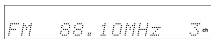
Selecting preset stations
Before selecting preset stations, you need to preset the radio stations. See "Preseting radio stations" on the left column of this page.
- Press TUNER to switch the input source to the tuner.
"FM" or "AM" appears in the display.
The band selected in this step will not affect the next step.
- Press PRESET on the remote controller or PRESET/ADJUST on the unit repeatedly to select the preset number of the desired radio station.

Erasing a preset station
- Select the preset channel you wish to erase.
- Press FM MODE while holding down MEMORY.
The selected preset channel will be erased.
Various functions common to all the sources
Turning on/off the speaker system A/B
You can turn on or off the speaker systems connected to the speaker system A and speaker system B connectors individually.
Before operating the remote controller, press RCVR/TAPE.
Press SPEAKER A on the unit or SP A on the remote controller to turn on or off the speaker system A.
Press SPEAKER B on the unit or SP B on the remote controller to turn on or off the speaker system B.
Note
If you turn on the speaker system B, the speaker system A also reproduces stereo sound automatically. (When a listening mode other than "Direct" is selected, the listening mode is set to "Stereo.")
The lit (speaker) A/B indicators indicate the corresponding speaker systems are on.
Muting the sound (remote controller only)
Press MUTING.
The MUTING indicator flashes in the display during the muting mode.
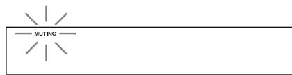
To restore the sound, press MUTING again.
Tip
If you turn off the unit during muting, and turn it on again, the sound will be restored.
Listening through headphones
Connect the plug of the stereo headphones to the PHONES jack on the AV Receiver.
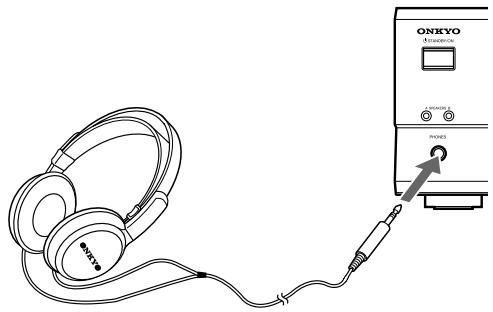
Notes
- The speakers will not reproduce sound while headphones are connected.
- When a listening mode other than "Direct" is selected, the listening mode is set to "Stereo" after connecting the headphones to the PHONES jack. When you disconnect the headphones, the listening mode returns to the previous mode.
- When the multi channel input is selected, only the sound of front L/R channel is heard. Press AUDIO SELECTOR (or AUDIO SEL) to select a mode other than "Multich".
Various functions common to all the sources
Changing the display
Press DISPLAY.
Each time you press DISPLAY, the screen changes as follows:
When an input source other than FM or AM is selected
| Input source + volume | DUD | 25 | ||
| ↓↑ | ↑ | |||
| Program format* | Do1by D | 3·2.1 | ||
| ↓ | ↑↓ | |||
| Input source + Listening mode (or Multich) | DUD | Do1by D | ||
Press DISPLAY once to initiate the program format display. Pressing the button again switches the display to the other display.
* When the input signal is digital audio
The program format is displayed. For example, the display "Dolby D: 3/2.1" shows that the format is Dolby Digital with 5.1 discrete channels consisting of three front channels (front left, front right, and center), two surround channels (surround left and surround right), and the low frequency effect (LFE) channel.
When the front channel number is 2, they are the front left and front right; when it is 1, it is monaural. When the surround channel number is 1, it is monaural; when it is 0, there is no surround channel. When no LFE number is given there is no LFE channel. Also, if there is no program format for the input signal, nothing will be displayed.
When the input signal is linear PCM
The sampling frequency is displayed. For example, the display "PCM fs: 44.1kHz " shows that the signal is PCM and that the sampling frequency is 44.1kHz .
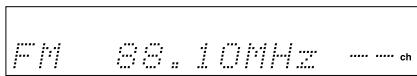
When FM or AM is selected as the input source
| FM/AM frequency + Preset no. | FM | 88.10MHz | 1 |
| ↑ | |||
| FM/AM + Listening mode | FM | Stereo |
Controlling the brightness of the display on the AV Receiver
Press DIMMER.
Each press of the button changes the brightness as follows:
| The display becomes less bright. |
| ↓ |
| The display is dimmed. |
| ↓ |
| The display becomes bright. |
Using the sleep timer (remote controller only)
Press SLEEP.
"Sleep 90 min" appears in the multipurpose display for about 5 seconds, which means the AV Receiver will turn off and enter standby mode in 90 minutes. Also the SLEEP indicator is lit in the display while the sleep timer is on.
Each press of the button makes the remaining time shorter by 10 minutes.
Checking the remaining time
Press SLEEP while the sleep timer is On.
The remaining time is displayed.
If you press SLEEP while the remaining time is displayed, the remaining time is reduced by 10 minutes.
Canceling the sleep timer
Press SLEEP repeatedly until the SLEEP indicator goes off.
Various functions common to all the sources
Adjusting each speaker's relative volume balance temporarily
You can readjust each speaker's relative volume balance according to your preference while listening to the sound.
The adjusted values will return to the values set on page 20 when the AV Receiver enters standby mode unless you save the values.
Note
You cannot adjust the volume balance while the muting function is activated.
1. While playing the source, press CH SEL repeatedly to check each speaker's relative volume balance.
Each press of the button changes the speaker and the selected speaker appears in the display in the following order:
Left (Front left) Center Right (Front right) Surr Right (Surround right) Surr Left (Surround left) Subwoofer Left ...
Note
- Any speaker that is not included in the speaker configuration on page 18 is not selected even if it is actually connected.
- The subwoofer will not output the test tone if it's off. See "Setting the subwoofer mode" on page 20.
2. Press CH SEL repeatedly to select the speaker, then press LEVEL / to adjust the volume level.
The volume level can be adjusted between -12dB and +12dB in 1 dB steps.
Repeat this step to change another speaker's volume balance.
When TEST is pressed after the above adjustment, the set levels will become the levels adjusted using the test tone by overwriting the existing ones.
Setting the input signal format
You can select the audio signal you wish to use, for each input source.
Auto: Setting to play a digital signal in priority. When a digital signal is not input, the analog signal will be played.
Multich: Setting to play back the input from the component connected to the DVD port (FRONT L/R, SURR L/R, CENTER and SUBWOOFER).
Analog: Setting to play the analog signal. Even when a digital signal is input, it will not be reproduced.
1. Press one of the input selector buttons.
2. Press AUDIO SELECTOR on the unit or AUDIO SEL on the remote controller.
The current setting is displayed for three seconds.
While the current setting is displayed, press AUDIO SELECTOR or AUDIO SEL repeatedly until the desired input signal format is displayed.
Each press of the button switches the displayed input format as follows: Auto (·)^* Multich** Analog Auto (back to the beginning)
- The name of the input terminals (OPT or COAX) is shown inside ( ).
"Auto" will be skipped when digital input jack is not assigned to the input source.
** "Multich" can be selected only when DVD is selected as the input source.
To fix the "Auto" to DTS or PCM
If there is a problem as described below, it is possible to fix the "Auto" to PCM or DTS.
- If the beginning of each PCM track is cut in Auto mode Fix the digital signal to PCM. However, care is required in using this mode for playback of a DTS-CD may be interfered by noise.
- If, during playback of a DTS-CD in Auto mode, noise is output when the CD is fast-forwarded or reversed Fix the digital signal to DTS.
1) Press AUDIO SELECTOR on the main unit (or AUDIO SEL on the remote controller) to select "Auto".
2) While "Auto" is displayed, press ADJUST / . Each press of the button switches the display between Auto PCM DTS Auto.
When the digital signal is fixed at DTS or PCM, the digital signal is reproduced only when the selected type of signal is input. Digital signals of other types are not reproduced. In this case, only the indicator of the non-reproduced source (PCM or DTS) will blink.
Note
Changing the digital input setting (see page 21) will cancel the selected input signal format. In such cases, set the input signal format again. If you had set the DVD input to "Multi", it will not change.
Enjoying multi channel sources
Using analog multi channel input
The multi channel input refers to a system, which is compatible with a source component equipped with analog 5.1-channel outputs (DVD player, MPEG decoder, etc.), reproducing the left/right front, center and left/right surround channels from five respective speakers and outputting the subwoofer channel from SUB WOOFER (refer to page 13).
1. Press DVD.
2. Press AUDIO SELECTOR on the unit or AUDIO SEL on the remote controller repeatedly to select "Multich".
3. Turn on the component connected to the DVD (FRONT L/R, SURR L/R, CENTER and SUBWOOFER) port and start playing the desired media.
Check that the DVD player is set for multi channel output. See instruction manual supplied with your DVD player for details.
4. If necessary, press CH SEL on the remote controller to select an individual speaker. Then press LEVEL / to adjust the output level as desired.
Adjust the speaker output level so that you can hear the same sound level from each speaker at the listening position. For the front right, front left, center, surround right and surround left speakers, the output levels can be adjusted between -12 to +12dB in 1 dB steps. The subwoofer can be adjusted between -30 to +12dB .
The volume levels from the speakers reproducing multi channel input source are independent from the speaker levels set using the test tone (page 20). These settings are not applied to speakers reproducing multi channel input source.
Applying the audio tone adjustment (Bass/Treble) effects to the audio
Before operating the remote controller, press RCVR/TAPE.
Press DIRECT on the unit or remote controller to set "Tone Off".
Press SURROUND on the unit or remote controller to set "Tone On".
Refer to page 30 to adjust audio.
Notes
- "Multich" can be selected only when DVD is selected as the input source.
- The surround mode cannot be selected when "Multich" is selected. Also, if "Multich" is selected during use of a surround mode, it is canceled automatically.
- Regardless of the speaker configuration, the input signal will be output to each corresponding speaker. For example, even if the speaker configuration is set to 2 ch, sound comes from all speakers.
Enjoying the listening modes
The surround sound of the AV Receiver enables you to enjoy the presence of a movie theater or concert hall in your room.
Before using any surround mode, make sure the Speaker Setup configurations have been set (see page 18).
The speaker configuration is very important for the surround sound. See "Positioning speakers/Connecting speakers" on pages 12 - 13. For operational instructions, refer to the page 29.
Following are the sound systems the AV Receiver can reproduce.
Dolby Digital surround, DTS (Digital Theater System) surround
This 5.1-channel digital surround format enables you to individually record and play five full-range (20 Hz-20 kHz) channels (left and right front, center, two surround channels) plus an LFE channel (Low Frequency Effect) for the low-range effect sound. It will create a realistic sound that could be heard in the theaters and concert halls.
Dolby Digital
Select this option when you play a DVD video that has a 100% probability of being marked.
DTS
Select this option when you play a DVD player, LD, or CD that has a mark.
- If you press the pause or skip button on the player while playing a DTS source, a short noise may be heard. This is not a malfunction.
- The DTS indicator on the HT-R420 lights up while it plays the DTS source. When playback concludes and the DTS signal transmission stops, the HT-R420 remains in DTS mode and the DTS indicator remains lit. This prevents noise when you operate the pause or skip button on the player. Therefore, if the source switches from the DTS signal to the PCM signal immediately, the PCM signal may not be played. In this case, stop the playback of the source on the player for about 3 seconds, then resume playback.
- Some CD players and LD players may be unable to play DTS sources correctly even if you connect the player to the HT-R420 digitally. This is because the digital signal has been processed (such as the output level, sampling frequency, frequency response, etc.), and the HT-R420 cannot recognize the signal as DTS data. Therefore, you may hear noise when you play a DTS source while processing the signal.
- The TAPE OUT or VIDEO 1 OUT jacks of the HT-R420 output analog audio. Do not record CDs or LDs that support DTS using these jacks. Otherwise, you will record a DTS encoded signal as noise.
Dolby Pro Logic II (Movie/Music)
This mode is a new generation 5-channel surround system that provides performance between the 4-channel (left front, right front, center, and monaural surround) Pro Logic Surround and the 5.1-channel Dolby Digital Surround. This mode can be set to the Movie mode designed for playing movies and the Music mode designed for listening to music.
In the Movie mode, the surround channels, which used to provide monaural output over only a narrow frequency range, now provide complete stereo output over the full frequency range. The result is viewing worth a realistic feel of movement.
The Music mode uses the surround channels to provide a natural sound space that cannot be provided with normal stereo output.
This mode can be used with VHS and DVD videos with the DOLBY SURROUND mark and certain television programs. The Music mode can be used with music compact discs and other stereo sources.
If no surround speakers are connected, then the surround sound is divided and output from the front left and right channels.
Onkyo's original Digital Signal Processing (DSP) modes
Analog sources include audio records, AM/FM broadcasting and cassette tapes. The PCM (Pulse Code Modulation) signal is a kind of digital audio signal, which is recorded directly on CD or DVD without being compressed. When an analog or PCM source is played, you can enjoy unique surround modes to Onkyo as listed below.
Orchestra
This mode is suitable for classical and opera music. The center channel is cut and the surround channels are emphasized to widen the stereo image. It simulates a natural reverberation as created in a large hall.
Unplugged
This mode is suitable for acoustic instrumental sounds, vocals, and jazz music. By emphasizing the front stereo image, it simulates the acoustics in front of the stage.
Studio-Mix
This mode is suitable for rock and popular music. Lively sounds with a powerful acoustic image will make you feel as if you are in a club.
TV Logic
This mode offers the realistic acoustics of a TV program being aired in the TV studio. It enhances the entire surround sound and clarity of conversation.
All Ch St (All Channel Stereo)
This mode is useful for background music. The front and surround channels will create a stereo image.
Stereo mode, Direct mode
Stereo
This mode has all input sound is output from the left and right front speakers. Subwoofer also can be used for playback.
Direct
This mode delivers pure sound with minimum sound quality adjustment and filtration. The sound recorded for the left and right front channel is output to the left and right front speakers only and not output to the subwoofer.
Enjoying the listening modes
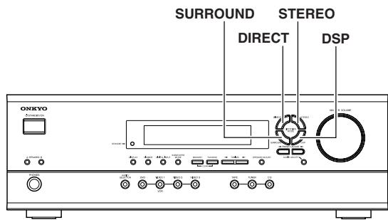
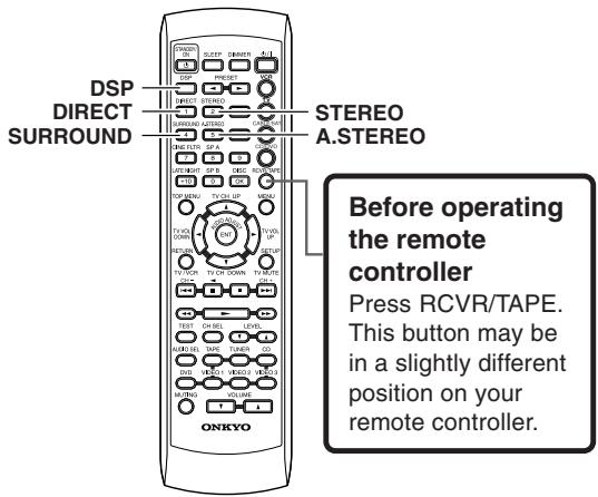
Selecting the listening mode
Before operating the remote controller, press RCVR/TAPE.
Press one of the listening mode buttons.
DIRECT button: Set the listening mode to "Direct".
STEREO button: Set the listening mode to "Stereo".
SURROUND button: Set the listening mode to "PLII" (when the sound is analog, PCM or Dolby Digital stereo source), "Dolby D" (when the sound is Dolby Digital) or "DTS" (when the sound is DTS).
A.STEREO button: Set the listening mode to "All Ch St".
DSP button on the front panel: Recall the Onkyo-original DSP mode. Each time this button is pressed, the listening mode cycles; "Orchestra" "Unplugged" "Studio Mix" "TV Logic" "All Ch St" "Orchestra" (back to the beginning).
DSP button on the remote controller: All of the listening modes that can be selected for the current source can be selected in sequence. This button is valid also when the remote control mode is other than RCVR/TAPE (see pages 35 - 37).
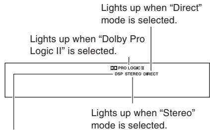
Lights up when Onkyo-original DSP mode ("Orchestra", "Unplugged", "Studio-Mix", "TV Logic" or "All Ch St") is selected.
The input source and available listening mode
| Input source signal format | Analog | PCM*1 | Dolby Digital | DTS | |
| Source software | Tape, FM/AM Video cassette tape | CD, Video CD, DVD Video, DVD Audio | DVD video, LD*2 | CD DVD Video, LD*2 | |
| Except 2/0 | 2/0 | ||||
| Direct | ● | ● | |||
| Stereo | ● | ● | ● | ● | ● |
| PL II Movie | ● | ● | ● | ||
| PL II Music | ● | ● | ● | ||
| Dolby D | ● | ||||
| DTS | ● | ||||
| Orchestra | ● | ● | |||
| Unplugged | ● | ● | |||
| Studio-Mix | ● | ● | |||
| TV Logic | ● | ● | |||
| All Ch St | ● | ● | |||
Notes
- Only "Stereo" ("Stereo" or "Direct" for PCM/Analog source) can be selected when the speaker configuration is set to "Speaker 2ch", when headphones are used, or when speakers B is selected.
- The listening mode cannot be selected when "Multich" is selected.
- You can select "Orchestra", "Unplugged", "Studio-Mix", "TV Logic" and "All Ch St", only when the speaker configuration is set to "Speaker 4ch" or "Speaker 5ch".
- If you select "Orchestra", no sound is reproduced from the center speaker even when the speaker configuration is set to "Speaker 5ch".
Audio adjust function
Using the audio adjust functions
Before operating the remote controller, press RCVR/TAPE.
These functions only work with speaker system A.
Audio Adjust provides various functions for adjusting the sound, including several especially for use with Dolby Digital, DTS, and Pro Logic II source.
The following table lists the Audio Adjust functions, their ranges and default values. Function availability depends on the current source and listening mode, as listed in the "The input source and available listening mode" column. See page 29 for information on listening modes.
| Function | Range | Default | Supported listening mode |
| Bass | -12 dB to +12 dB in 2 dB steps | 0 dB | All modes except Direct |
| Treble | |||
| Late Night | Low, High, Off | Off | Dolby Digital |
| Cinema Filter (Cine Fltr) | On, Off | Pro Logic II Movie Dolby Digital DTS DTS Neo:6 Cinema | |
| Panorama | On, Off | Off | Pro Logic II Music |
| Dimension | 0, 1, 2, 3, 4, 5, 6 | 3 | |
| Center Width | 0, 1, 2, 3, 4, 5, 6, 7 |
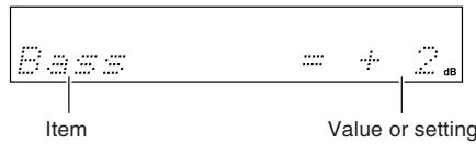
- Press AUDIO ADJUST (repeatedly) until the item to be adjusted is displayed.
- Press PRESET/ADJUST on the unit or ADJUST on the remote controller to adjust the item.
Refer to the right column for AUDIO ADJUST items and settings.
Note
Cinema Filter and Late Night can also be adjusted from the remote control.
Press the CINE FLTR or LATE NIGHT button to display the current setting (On or Off). To change the current setting, press the same button again.
Remote controller
Remote controller
Audio adjust function
The Audio Adjust functions are explained below.
Bass
With this function you can boost or cut low-frequency sounds output by the front speakers from -12dB to +12dB in 2 dB steps.
Treble
With this function you can boost or cut high-frequency sounds output by the front speakers from -12dB to +12dB in 2 dB steps.
Late Night (Only for Dolby Digital source)
With this function you can reduce the dynamic range of Dolby Digital source so that you can still hear quiet parts even when listening at low volume levels—ideal for watching movies late at night when you don't want to disturb anyone.
Late Night = Off ......... no effect
Late Night = Low ....... small reduction in dynamic range
Late Night = High .......big reduction in dynamic range
Note that the impact of the Late Night function depends on the Dolby Digital source that you are playing, and with some source there will be little or no effect.
This function is automatically cancelled when you set the HT-R420 to Standby.
Cinema Filter
When this function is on, you can soften the harshness, or brightness sometimes experienced with movie soundtracks, which are typically mixed for reproduction in a movie theater.
Panorama (Pro Logic II Music)
When this function is on, you can extend the front stereo image to the surround speakers to provide a "wraparound" effect, especially useful when not much sound is being output by the surround speakers.
Dimension (Pro Logic II Music)
When this function is on, you can move the soundfield backward or forward.
With a setting of 3, the soundfield is in the normal position. Choose a lower setting to move the soundfield forward. Choose a higher setting to move it backward.
If the stereo image is too wide, or there's too much surround information, try moving the soundfield forward to achieve a better balance. If the stereo image is too narrow, or it sounds almost like it's in mono, try moving the soundfield backward.
Center Width (Pro Logic II Music)
In Pro Logic II decoding, the center-channel signal is output by the center speaker. If a center speaker is not used, the decoder divides the center signal equally between the front left and right speakers, producing what's known as a "phantom" center. With this function you can choose to have the center-channel signal output by only the center speaker, by only the front left and right speakers ("phantom" center), or by a mix of the two.
With a setting of 0, the center-channel signal is output only by the center speaker.
With a setting of 7, it's output only by the front left and right speakers ("phantom" center).
In home theaters, adding some width to the center channel can improve the balance between the center and front left and right speakers. Most stereo source will benefit from appropriate use of this function. The recommended setting for Pro Logic II Music mode is 3. For Pro Logic II Movie mode, the setting is automatically set to 0.
Recording a source
To record the input source signal you are currently watching or listening to
Recording of video and/or audio signals can be performed on the components connected to the VIDEO 1 OUT and TAPE OUT (audio only) jacks.
Input selector buttons
1. Press an input selector button to select the input source to record.
The input source is now selected and you may watch or listen to it as desired. The currently selected input source signal to the VIDEO 1 OUT and TAPE OUT outputs for recording.
2. Start recording at the recording component as desired.
Notes
- You can record analog audio, but not digital audio. Make sure that you have made a correct analog connection.
- If you change the input source during recording, you will record the signals from the newly selected input source.
- You cannot record the surround effects.
- Only the FRONT L/R audio can be recorded when inputting multi channel signals to the DVD jack.
Recording the video from one source and the audio from another
You can add the sound from one source to the video of another source to make your own video recordings.
Below is an example of recording the sound from a CD player connected to CD L/R jacks and the video from a video camera connected to VIDEO 3 INPUT VIDEO jack to video cassette tape in a video cassette recorder connected to the VIDEO 1 OUT L/R and VIDEO jacks.
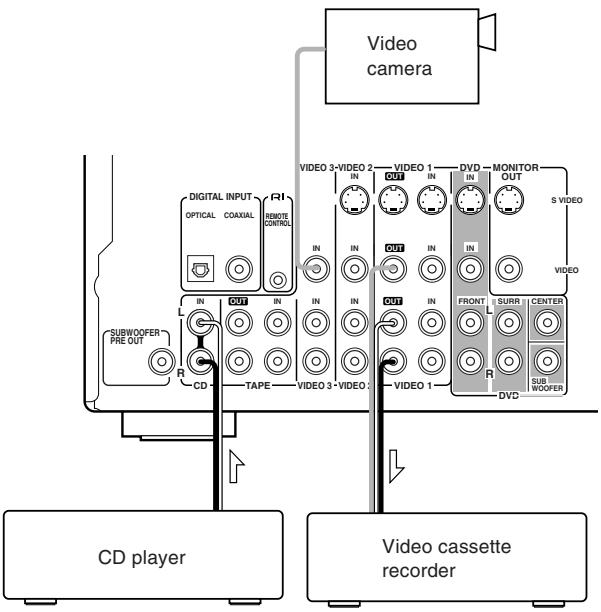
- Insert a CD in the CD player and insert a tape in the video camera connected to the VIDEO 3 INPUT.
-
Insert a video tape for recording in the video cassette recorder connected to VIDEO 1 OUT.
-
Press VIDEO 3.
- Press CD.
This switches the audio output to CD, but the video output remains Video 3 that has been selected in step 3.
5. Start recording on the video cassette recorder and start playing at the CD player and video camera as desired.
The recorded video signal becomes the output from the video camera and recorded audio signal becomes that from the CD player.
Notes
- You can record analog audio, but not digital audio. Make sure that you have made a correct analog connection.
- If you change the input source during recording, you will record the audio signals from the newly selected input source and the video signals assigned to that input source.
- You cannot record the surround effects.
Using the remote controller with your other AV components
Connecting your Onkyo CD player, Onkyo DVD player, or Onkyo cassette recorder to the HT-R420's RI connector allows you to control it with the HT-R420's remote controller. Since you only need to point the remote controller at the HT-R420, you can control components that are out of sight, for example, in a cabinet. Since you don't have to enter any special codes, or do any programming,
RI allows you to control your Onkyo AV components quickly and easily. See page 16 for connection information.
Entering the manufacturer's code (RC-518M only)
If you're using an Onkyo CD player connected to the HT-R420's RI connector, an Onkyo AV component without an RI connection, or an AV component made by another manufacturer, do the following.
When you operate an AV component, you point the remote controller at the AV component, not the HT-R420.
1. Determine the appropriate manufacturer's code from the list on the next page.
Where several codes are listed, try the first one, and if that doesn't work, try the others until you find one that does.
2. Turn on the AV component that you want to be able to control (e.g., CD, DVD, or TV).
Next you must assign the AV component to one of the remote controller's mode buttons. Note that you must do step 4 within 10 seconds of step 3.
3. While holding down the remote controller's VCR, TV, CABLE/SAT, or CD/DVD button, press the ENT button.
For the CD/DVD button, you can enter a CD code or DVD code, not both. And for the CABLE/SAT button, a Cable code or Satellite code, not both.
4. Within 10 seconds, use the remote controller's number buttons to enter the manufacturer's code.
5. Check to see if you can control the AV component from the remote controller.
If it works as expected, the code has been entered correctly. If not, go back to step 3 and try again.
Note that with some manufacturer's AV components, some of the remote controller's buttons may not work as expected.
By default, the CD/DVD button is set to code 316, which is for use with an RI-compatible Onkyo DVD player connected to the HT-R420's RI connector. To control an RI-compatible Onkyo CD player connected to the HT-R420's RI connector, you must enter code 300. To control an Onkyo DVD player without an RI connection, you must enter either code 301 or 313. The CD/DVD button can be used with only one AV component.
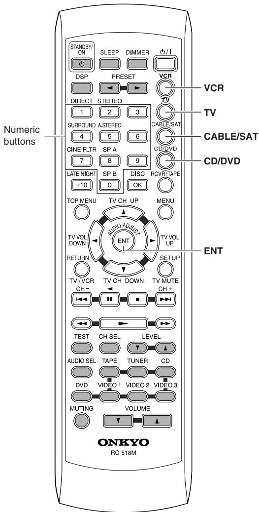
Using the remote controller with your other AV components
| Manufacturer | TV | VCR | DVD | Cable | Satellite |
| AIWA | 137 | ||||
| AKAI | 227 | ||||
| DENON | 302 | ||||
| ECHOSTAR | 500 | ||||
| EMERSON | 228 | ||||
| FISHER | 200 | 100, 101, 102, 140 | |||
| GE | 103, 104 | ||||
| GE • PANA | 201, 202 | ||||
| GE • RCA | 203 | ||||
| GEMINI | 401 | ||||
| GENERAL INSTRUMENT | 501 | ||||
| G.I. | 400 | ||||
| GO VIDEO | 105, 106, 107 | ||||
| GOLD STAR | 204, 205 | 108 | |||
| HAMILIN | 402, 403, 404, 405 | ||||
| HITACHI | 206, 207 | 103, 109 | 303 | 502 | |
| HUGHS NETWORK SYSTEM | 503 | ||||
| JERROLD | 406, 407, 408, 409, 410, 411, 412, 413, 414 | ||||
| JVC | 208 | 110, 111, 112, 113 | 304 | ||
| KENWOOD | 305 | ||||
| MACOM | 415, 416, 417 | ||||
| MAGNAVOX | 209, 210 | 114, 115, 116 | 306 | 418 | |
| MARANTZ | 211 | 307 | |||
| MITSUBISHI | 117, 118, 119, 120, 121, 139 | 308 | |||
| NEC | 136 | ||||
| OAK | 419, 420, 421 | ||||
| ONKYO | 301, 313, 316 (for R/DVD), 300 (for CD) | ||||
| PANASONIC | 212, 213 | 122, 123 | 309 | 422, 423 | 504, 505, 506 |
| PHILIPS | 214 | 114 | 424, 425, 426, 427, 428, 429 | ||
| PIONEER | 215 | 310 | 430, 431 | ||
| PRIMESTAR | 507 | ||||
| PROSCAN | 216 | 311 | 508, 509, 510 | ||
| RCA | 217, 218, 219, 220, 229, 230 | 109 | 311 | 508, 509, 510 | |
| S.ATLANTA | 432, 433, 434 | ||||
| SAMSUNG | 221, 222 | 124, 125, 126 | 304 | 435 | |
| SHARP | 223 | 127, 128 | |||
| SHINTOM | 138 | ||||
| SONY | 224 | 129, 130, 131, 132, 133, 141 | 312 | 511 | |
| TOCOM | 436 | ||||
| TOSHIBA | 134 | 313 | 512 | ||
| YAMAHA | 314 | ||||
| ZENITH | 225, 226 | 135 | 315 | 437, 438 |
Using the remote controller with your other AV components
Using the RC-518M
If you need to enter the manufacturer's code for your AV component into the remote controller, see page 33.
- Point the remote controller at the HT-R420 and use the input selector buttons to select an input source for the HT-R420.
- Use the remote controller's mode buttons (i.e., VCR, TV, CABLE/SAT, CD/DVD, or RCVR/TAPE) to select a remote controller mode.
(You don't have to point the remote controller at anything for this step.)
- Use the remote controller's Power /1 button to turn on the AV component.
Remember, if your AV component is connected to the HT-R420 via RI, point the remote controller at the HT-R420. If not, point the remote controller at the AV component.
(A cassette recorder can't be turned on or off from the remote controller. You must use its POWER switch.)
- Use the buttons as explained below.
In the following illustrations, buttons that control the HT-R420 regardless of which mode is selected are shaded. When you want to control the HT-R420 fully, press the RCVR/TAPE button, then you can use all the buttons that apply to the HT-R420.
Using the RC-479S
- Point the remote controller at the HT-R420 and use the input selector button to select an input source for the HT-R420.
- Use the remote controller's mode buttons (i.e., DVD, CD, RCVR/TAPE) to select a remote controller mode.
(You don't have to point the remote controller at anything for this step.)
- Use the remote controller's Power /1 button to turn on the AV component. Point the remote controller at the HT-R420.
(A cassette recorder can't be turned on or off from the remote controller. You must use its POWER switch.)
- Use the buttons as explained below.
In the following illustrations, buttons that control the HT-R420 regardless of which mode is selected are shaded. When you want to control the HT-R420 fully, press the RCVR/TAPE button, then you can use all the buttons that apply to the HT-R420.
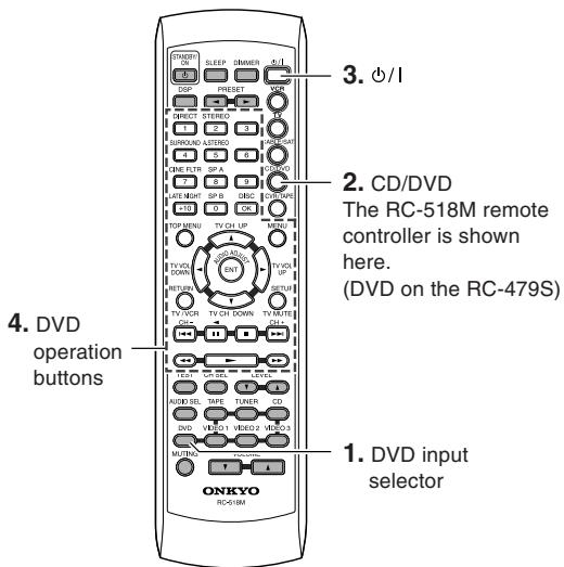
(RC-518M/RC-479S)
DVD mode
RC-518M:
You must enter the appropriate manufacturer's code for your DVD player (see page 33).
/ : PowerOn/Off.
Starts playback of DVD.
■: Stops playback.
: Searches the disc in the forward direction.
Searches the disc in the reverse direction.
II: Lets playback pause temporarily or advances the disc frame by frame.
▶▶1: Starts playback from the beginning of the next chapter/track.
Starts playback from the beginning of the current chapter/track.
DISC : This button is valid when the DVD changer is used and selects the disc to be played.
1-9, +10, 0: Use to enter numeric values.
TOP MENU : Displays the top menu of each DVD disc.
MENU: Displays a menu recorded in the DVD disc.
RETURN: Returns to the previous menu.
SETUP : Displays the setup menu.
/ / / : Selects an item in a menu.
ENT: Enters the selection in memory.
Note
RC-518M:
Since you can only enter a CD code or DVD code for the CD/DVD button, you can use CD mode or DVD mode, but not both.
Using the remote controller with your other AV components
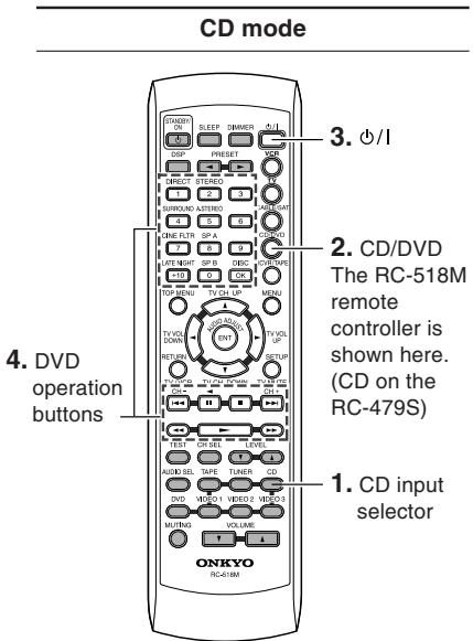
(RC-518M/RC-479S)
(RC-518M/RC-479S)
(RC-518M)
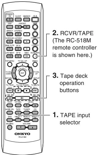
Tape mode (RCVR/TAPE)

VCR mode (VCR)
BC-518M:
CD mode can be used only with an Onkyo CD player, and you must enter the appropriate Onkyo CD player code (see page 33).
/ : PowerOn/Off.
Starts playback of CD.
Stops playback, fast forward or fast reverse.
Fast forwards of CD.
Fast reverses of CD.
II: Lets playback pause temporarily.
▶▶1: Skips to the beginning of the next track.
: Skips to the beginning of the current or previous track.
DISC : This button is valid when the CD changer is used and selects the disc to be played.
1-9, +10, 0: Use to enter numeric values.
Note
BC-518M:
Since you can only enter a CD code or DVD code for the CD/DVD button, you can use CD mode or DVD mode, but not both.
Plays side A (the side facing the front) of tape.
Stops playback, recording, fast forward or rewinding.
Fast forwards the tape.
: Rewinds the tape.
Plays side B (the side facing the rear) of the tape.
Note
Since this is RCVR/TAPE mode, you can control the cassette recorder and fully control the HT-R420 at the same time.
You must enter the appropriate manufacturer's code (see page 33).
TV CH UP ▲: Changes the received channel upward.
TV CH DOWN
Changes the received channel downward.
Starts playback of videotape.
: Stops playback, recording, fast forward or rewinding.
Fast-forwards the videotape.
: Rewinds the videotape.
: Changes the VCR channel downward.
▶▶1: Changes the VCR channel upward.
I: Lets playback pause temporarily.
Using the remote controller with your other AV components
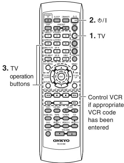
(RC-518M)
TV mode (TV)
You must enter the appropriate manufacturer's code (see page 33).
/ : PowerOn/Off.
1 - 9, + 10,0 : Use to enter numeric values.
OK: Confirm.
TV CH UP ▲: Changes the TV channel upward.
TV CH DOWN : Changes the TV channel downward.
TV VOL UP: Increases the TV volume.
TV VOL DOWN : Decrease the TV volume
TV/VCR: Switches the TV/VCR inputs.
TV MUTE: Mutes the sound.
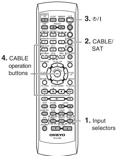
(RC-518M)
Cable mode (CABLE/SAT)
You must enter the appropriate manufacturer's code (see page 33).
/ : PowerOn/Off.
1-9,0: Use to enter numeric values.
CH+: Changes the channel upward.
CH-: Changes the channel downward.
ENT: Confirm.
Note
Since you can only enter a Cable code or Satellite code for the CABLE/SAT button, you can use Cable mode or Satellite mode, but not both.
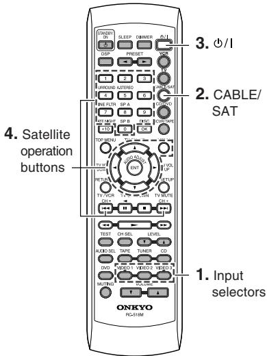
(RC-518M)
Satellite mode (CABLE/SAT)
You must enter the appropriate manufacturer's code (see page 33).
ENT: Confirm the selection.
CH+: Changes the preset channel upward.
CH-: Changes the preset channel downward.
Note
Since you can only enter a Cable code or Satellite code for the CABLE/SAT button, you can use Cable mode or Satellite mode, but not both.
Troubleshooting
Check the following guide for the possible cause of a problem before contacting service. Refer also to the respective instruction manuals of the connected components and TV.
| \ | Symptoms | Causes | Remedies | Pages |
| Amplifier | The AV receiver doesn't switch on. | · The power cord is disconnected. · There is external noise interfering with the computer circuits of the AV receiver. | · Check the connection of the power cord. · Disconnect the power cord, then connect it again. | 17 17 |
| Power shuts off immediately after power on. | · Amplifier protection circuitry has been activated. | · Contact your Onkyo Service Center. | - | |
| The buttons on the remote controller and AV receiver do not operate. | · Power supply fluctuations or other abnormalities such as static electricity may interrupt correct operation. | · Disconnect the power cord, then connect it again. | - | |
| No sound is reproduced. | · The muting function is activated. · The AV receiver is not properly connected. · Input selector is not set properly. · Headphones are connected. · The input signal format is set to "PCM" or "DTS". | · Deactivate the muting function. · Check the connections to the AV receiver. · Set to correct input source. · Decrease the volume, then disconnect the headphones. · Set the input signal format to "Auto". | 24 10, 11 17, 22 24 - | |
| No sound or very little sound is reproduced from the center speaker. | · The speakers are not properly connected. · The listening mode is set to "Stereo" or "Orchestra". · The volume level of the center speaker ("Center") is set to minimum. · A speaker configuration without the center speaker is selected. | · Check the speaker connections. · No sound is reproduced from the center speaker when the listening mode is "Stereo" or "Orchestra". · Adjust the volume level of the center speaker. · Check that the selected speaker configuration includes the center speaker. | 13 29 20, 26 18 | |
| Hum, low-frequency noise. | · The placement of the audio connection cables on the rear panel is incorrect. | · Adjust the placement of the cable to reduce hum. | - | |
| Rough or scratchy sound. High range is not clear. | · Treble control too high. | · Use audio adjust function to cut the treble response. | 30 | |
| No sound or very low volume from subwoofer. | · Subwoofer mode is set to "Off". · Subwoofer mode setting is improper. | · Check the subwoofer mode setting. · Check the subwoofer mode setting. | 20 20 | |
| No picture appears on the TV screen. | · The TV is not set to receive the output signals from the AV receiver. · The video cable is not connected securely. · Only the S video connection is made. | · Set the TV to the AV receiver's input. · Check the connections between the AV receiver and TV set. · Also make video connection. Check the TV's video input and AV receiver's output signal. | - 10 10, 11 | |
| The sound of the playback source is not heard. | · Another input source is selected. | · Select the appropriate input source. | 17, 22 | |
| Remote controller | The buttons on the AV receiver operate but the buttons on the remote controller do not operate. | · Any wrong mode button is pressed. · No batteries are inserted in the remote controller. · The batteries are worn out. · The remote controller is not pointed at the remote sensor of the AV receiver. · The remote controller is too far from the AV receiver. | · Press the appropriate mode control button. · Insert new batteries. · Replace with new batteries. · Point the remote controller at the remote sensor of the AV receiver. · Operate the remote controller within 16 feet (5 m). | 35-37 5 5 5 5 |
Troubleshooting
| Symptoms | Causes | Remedies | Pages | |
| Tuner | Too much noise is heard or sound is interrupted occasionally. (The FM STEREO indicator does not light steadily.) | ·FM stereo waves may produce a hiss noise when a certain level is reached. ·The position or direction of the FM antenna is incorrect. ·The station is too weak. | ·Press the FM MODE button to go off the FM STEREO indicator. ·Adjust the position, height, and direction of the FM antenna. ·Connect an FM outdoor antenna. Try to use an antenna with more elements. [For installation of the outdoor antenna, consult your nearest dealer as it requires special skills and experience.] | 22 14, 15 15 |
| Sound is distorted or sound volume decreases. | ·The radio wave is distorted. ·Cars are running or airplanes are flying near the house. | - | - | |
| Sound is excessively distorted. | ·There is a tall building or a mountain nearby. [The waves transmitted from the transmission center (direct waves) and the waved reflected by buildings or mountains (diffraction waves) interfere with each other causing multi pass distortion.] | - | - | |
| No preset channels are selected. | ·The power cord is unplugged for a long time. | ·The preset data in memory is lost. Preset the radio stations again. | 23 | |
| Recording | Sound is reproduced from the speakers but not recorded. | ·The sound system you are trying to record is DTS or Dolby Digital surround. | ·Make an analog connection. | 32 |
| Other | LATE NIGHT function cannot be used. | ·Playback source is not Dolby Digital encoded. | ·Check that the ☐ DIGITAL indicator lights up in the display. | 17 |
| Multichannel audio is not output. | ·Input signal format is set to "Auto" or "Analog". ·The component is not connected to the DVD jacks. ·The DVD player output settings are incorrect. | ·Set the input signal format to "Multich". ·Check that the multichannel output jacks of the component is connected to the DVD FRONT L/R, SURROUND L/R, CENTER and SUBWOOFER jacks. ·See the instruction manual supplied with your DVD player, and check that it is set for multi channel output. | 26 11 - | |
Memory Preservation
This unit does not require memory preservation batteries.
A built-in memory power backup system preserves the contents of memory during power failures and even when the power cord is unplugged.
The power cord must be plugged in order to charge the backup system. The memory preservation period after the unit has been turned off varies depending on climate and placement of the unit. On average, memory contents are protected over a period of a few weeks after the time the unit has been turned off. This period is shorter when the unit is exposed to a very humid climate.
When incorrect operation is observed
- The HT-R420 contains an internal microcomputer that performs high-level operations. However, on extremely rare occasions, noise or interference from an external source or static electricity may cause faulty operation. If this occurs, unplug the power cord from the wall outlet, wait five or more seconds, and then plug it back in. This should correct the situation.
- To reset the surround mode and other settings to the factory default settings, hold down the VIDEO 1 button with the HT-R420 turned on and then press the STANDBY/ON button. "Clear" appears in the front display and the HT-R420 enters the standby state.
Specifications
Amplifier Section
Power Output:
American model:
(All Channel)
100 W + 100 W (8 Ω, 20 Hz~20 kHz, FTC)
Australian model:
110W + 110W (8Ω,1kHz,DIN)
Asian model:
140 W + 140 W (8 Ω, 1 kHz, JEITA)
Dynamic Power:
230W + 230W (3 ,Front)
170W + 170W (4Ω, Front)
115 W + 115 W (8 Ω, Front)
THD
(Total Harmonic Distortion):
0.08% (Power Rated)
Damping Factor:
60 (Front, 1kHz, 8Ω)
Input Sensitivity and Impedance: 200mV / 47k (LINE)
Output Level and Impedance:
10Hz 100kHz / + 1dB - 3dB (Direct
Frequency Response:
mode)
Tone Control:
+12 dB, -12 dB, 50 Hz (BASS)
+12 dB, -12 dB, 20 kHz (TREBLE)
SN Ratio:
100 dB (CD, IHF-A)
Speaker Impedance:
8~16Ω
Video Section
Input Sensitivity/Output Level and Impedance:
1 Vp-p /75Ω (Component and S-Video Y)
0.7 Vp-p /75Ω (Component Pb/Cb,Pr/Cr)
0.28 Vp-p/75Ω (S-Video C)
1 Vp-p /75Ω (Composite)
Tuner Section
FM
Tuning Frequency Range:
87.5 MHz~108.0 MHz
Stereo 17.2 dBf 2 V (75Ω IHF)
Mono 11.2 dBf 1 V (75Ω IHF)
Usable Sensitivity:
Stereo 70 dB (IHF-A)
Mono 76 dB (IHF-A)
S/N Ratio:
Stereo 0.3% (1kHz)
Mono 0.2% (1kHz)
30Hz 15kHz / + 1 dB, -1 dB
45dB(1kHz)
Stereo Separation:
AM
Tuning Frequency Range:
American model: 530kHz 1710kHz
Australian model: 522kHz 1611kHz
Others model: 530kHz 1710kHz
522kHz 1611kHz
Useable Sensitivity:
30~ V
S/N Ratio:
40 dB
THD:
0.70%
General
Power Supply:
American model: AC 120 V, 60 Hz
Others: AC 230-240 V, 50 Hz
AC 120/220-230 V, 50/60 Hz
Power Consumption:
American model: 4.7A
Australian and Worldwide model: 300 W
Stand-by Power Consumption: 1.6 W
Dimensions:
435 W x 150 H x 374 D mm
17 1/8 W x 5 7/8 H x 14 3/4 D inches
Weight:
8.8kg
19.4 lbs
Video Inputs
S-Video Compatible Jack Input: DVD,VIDEO1,VIDEO2
Digital Inputs: 1 (Optical), 1 (Coaxial)
Analog Inputs: DVD (MULTICHANNEL), CD, TAPE,
Speaker Outputs: 5+2
Phones: 1
Specifications and features are subject to change without notice.
ONKYO CORPORATION
Sales & Product Planning Div. : 2-1, Nisshin-cho, Neyagawa-shi, OSAKA 572-8540, JAPAN
Tel: 072-831-8023 Fax: 072-831-8124
18 Park Way, Upper Saddle River, N.J. 07458, U.S.A.
Tel: 201-785-2600 Fax: 201-785-2650 http://www.onkyousa.com
ONKYO EUROPE ELECTRONICS GmbH
Liegnitzerstrasse 6, 82194 Groebenzell, GERMANY
Tel: +49-8142-4401-0 Fax: +49-8142-4401-555 http://www.onkyo.net
ONKYO CHINA LIMITED
Units 2102-2107, Metroplaza Tower I, 223 Hing Fong Road, Kwai Chung,
N.T., HONG KONG Tel: 852-2429-3118 Fax: 852-2428-9039

http://www.onkyo.com/
10407-5
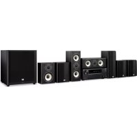
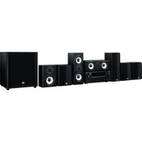
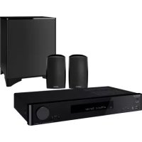
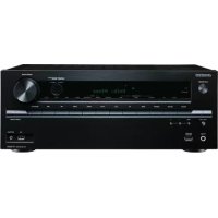
- Contents
- Before using
- Facilities and connections
- Enjoying music or videos
- Remote controller
- Appendix
- WARNING:
- CAUTION:
- WARNING
- AVIS
- Important Safety Instructions
- Precautions
- For U.S. models
- Note to CATV system installer:
- FCC information for user
- NOTE:
- For Canadian models
- Power
- Features
- Amplifier Features
- FM/AM Tuner Features
- Supplied accessories
- Power-plug adapter
- 75/300-ohm antenna adapter
- Before Using the HT-R420
- Setting the Voltage Selector (Worldwide model only)
- Installing the Batteries
- Notes
- Using the Remote Controller
- Index to parts and controls
- Display
- Rear panel
- Tip
- Connecting to audio/video equipment
- Before connecting
- Video Connection Formats
- Positioning speakers/Connecting speakers
- Standard speaker placement of the speaker system A
- Front
- Surround
- Subwoofer
- How to connect to the speaker terminals
- Connecting antennas
- USA, Canada, Mexico
- Australia
- Other models
- Adjusting the position of the FM indoor antenna
- Note
- Adjusting the position of the AM indoor antenna
- Connecting an Outdoor FM Antenna
- Using the 75/300-ohm Antenna Adapter
- Connecting 300-ohm Flat Cable
- Connecting 75-ohm Coaxial Cable
- Using a TV/FM Antenna Splitter
- Connecting an Outdoor AM Antenna
- Connections for remote control (R I)
- Power on/ready function
- Direct change function
- Power off function
- Enjoying music or videos with the HT-R420
- Connecting the power
- Connect the power cord to a wall outlet.
- Press STANDBY/ON.
- Selecting a source
- Press input selector button to select one of the following input sources:
- Ensure that the A and/or B indicator(s) for the speaker system(s) to be used are lit on the display.
- Start playing the selected source.
- Press VOLUME / on the remote controller or turn MASTER VOLUME dial on the unit to adjust the volume.
- About digital sound
- Speaker setup
- Selecting the number of speaker channels
- Press SPEAKER ADJUST once.
- Press PRESET/ADJUST repeatedly to select the number of channels.
- Setting the crossover frequency
- Home theater in a box
- Press SPEAKER ADJUST twice.
- Press PRESET/ADJUST repeatedly to select the crossover frequency.
- Specifying speaker distances
- Measure and make a note of the distance from each speaker to the listening position.
- Press the SPEAKER ADJUST three times.
- Center
- Surr Right
- Surr Left
- Press PRESET/ADJUST repeatedly to specify the speaker distance.
- Repeat steps 2 and 3 for all five parameters.
- Setting the subwoofer mode
- Press SUBWOOFER MODE on the unit.
- → Subwoofer Mode 1 (Default)
- Subwoofer Mode 2
- Subwoofer Mode 3
- Subwoofer Off
- Adjusting each speaker's relative volume balance — Test tone
- Press TEST on the remote controller.
- Press CH SEL repeatedly to select the speaker, then press LEVEL / on the remote controller to adjust the volume level.
- When you have completed the adjustment by repeating step 2, press TEST.
- Changing the default settings according to your connections
- Switch the source from TAPE to MD
- Setting the digital inputs
- Listening to the radio
- Tuning into a radio station
- Press TUNER.
- Using the TUNING buttons on the front panel, tune into the station you desire.
- Tuning in a weak frequency (only for FM stations)
- Presetting radio stations
- Selecting preset stations
- Erasing a preset station
- Various functions common to all the sources
- Turning on/off the speaker system A/B
- Muting the sound (remote controller only)
- Press MUTING.
- Listening through headphones
- Changing the display
- Press DISPLAY.
- When an input source other than FM or AM is selected
- * When the input signal is digital audio
- When the input signal is linear PCM
- When FM or AM is selected as the input source
- Controlling the brightness of the display on the AV Receiver
- Press DIMMER.
- Using the sleep timer (remote controller only)
- Press SLEEP.
- Checking the remaining time
- Canceling the sleep timer
- Adjusting each speaker's relative volume balance temporarily
- While playing the source, press CH SEL repeatedly to check each speaker's relative volume balance.
- Press CH SEL repeatedly to select the speaker, then press LEVEL / to adjust the volume level.
- Setting the input signal format
- Press one of the input selector buttons.
- Press AUDIO SELECTOR on the unit or AUDIO SEL on the remote controller.
- To fix the "Auto" to DTS or PCM
- Enjoying multi channel sources
- Using analog multi channel input
- Press DVD.
- Press AUDIO SELECTOR on the unit or AUDIO SEL on the remote controller repeatedly to select "Multich".
- Turn on the component connected to the DVD (FRONT L/R, SURR L/R, CENTER and SUBWOOFER) port and start playing the desired media.
- If necessary, press CH SEL on the remote controller to select an individual speaker. Then press LEVEL / to adjust the output level as desired.
- Applying the audio tone adjustment (Bass/Treble) effects to the audio
- Enjoying the listening modes
- Dolby Digital surround, DTS (Digital Theater System) surround
- Dolby Digital
- DTS
- Dolby Pro Logic II (Movie/Music)
- Onkyo's original Digital Signal Processing (DSP) modes
- Orchestra
- Unplugged
- Studio-Mix
- TV Logic
- All Ch St (All Channel Stereo)
- Stereo mode, Direct mode
- Stereo
- Direct
- Selecting the listening mode
- Press one of the listening mode buttons.
- Audio adjust function
- Using the audio adjust functions
- Bass
- Treble
- Late Night (Only for Dolby Digital source)
- Cinema Filter
- Panorama (Pro Logic II Music)
- Dimension (Pro Logic II Music)
- Center Width (Pro Logic II Music)
- Recording a source
- To record the input source signal you are currently watching or listening to
- Press an input selector button to select the input source to record.
- Start recording at the recording component as desired.
- Recording the video from one source and the audio from another
- Start recording on the video cassette recorder and start playing at the CD player and video camera as desired.
- Using the remote controller with your other AV components
- Entering the manufacturer's code (RC-518M only)
- Determine the appropriate manufacturer's code from the list on the next page.
- Turn on the AV component that you want to be able to control (e.g., CD, DVD, or TV).
- While holding down the remote controller's VCR, TV, CABLE/SAT, or CD/DVD button, press the ENT button.
- Within 10 seconds, use the remote controller's number buttons to enter the manufacturer's code.
- Check to see if you can control the AV component from the remote controller.
- Using the RC-518M
- Using the RC-479S
- Troubleshooting
- Memory Preservation
- When incorrect operation is observed
- Specifications
- Amplifier Section
- Video Section
- Tuner Section
- General
- Video Inputs
- ONKYO CORPORATION
- ONKYO EUROPE ELECTRONICS GmbH
- ONKYO CHINA LIMITED
Brand : ONKYO
Model : HT-S670
Category : Home theater audio system