
AVR 430 - AV receiver HARMAN KARDON - Free user manual and instructions
Find the device manual for free AVR 430 HARMAN KARDON in PDF.

| Product Type | 7.1-channel audio-video receiver |
| Brand | HARMAN KARDON |
| Model | AVR 430 |
| Dimensions (W × H × D) | 440 × 165 × 380 mm |
| Weight | 14 kg |
| Power supply | 120 V ~ 60 Hz (Canadian model), max power consumption 1200 W |
| Output power | 7 × 75 W (8 Ω, 20 Hz – 20 kHz, 0.07 % THD) |
| Decodable audio formats | Dolby Digital, DTS, Dolby Pro Logic II, DTS Neo:6 |
| Inputs | 5 HDMI (1080p compatible), 3 component, 6 composite, 7 digital audio (optical/coaxial), 8 analog |
| Outputs | 1 HDMI (with audio return), 1 component, 1 composite, 2 subwoofer, 7.1 preamp, headphones |
| Tuner | AM/FM with 30 presets |
| Multiroom functions | Zone 2 audio (analog) and video (composite) |
| Network connection | RS-232, 12 V trigger, IR input |
| Display | Multi-segment fluorescent display |
| Maintenance and cleaning | Unplug the device before cleaning. Use a soft dry cloth. Do not use abrasive products. |
| Safety | Use the polarized plug as indicated. Do not expose to moisture. Do not block ventilation openings. |
| Spare parts and repairability | Contact an authorized HARMAN KARDON service center. Repairability index: 6/10 (estimate). |
| General information | Manual available in French (52 pages). Model complies with Canadian standard NMB-003. |
Frequently Asked Questions - AVR 430 HARMAN KARDON
User questions about AVR 430 HARMAN KARDON
0 question about this device. Answer the ones you know or ask your own.
Ask a new question about this device
Download the instructions for your AV receiver in PDF format for free! Find your manual AVR 430 - HARMAN KARDON and take your electronic device back in hand. On this page are published all the documents necessary for the use of your device. AVR 430 by HARMAN KARDON.
USER MANUAL AVR 430 HARMAN KARDON
Power for the Digital Revolution
AVR 430
Sun: Mode V Surround Select A V Tuning A AM/FM P Preset A Source A Tun Model
①
3 Introduction
4 Safety Information
4 Unpacking
5 Front-Panel Controls
8 Rear-Panel Connections
11 Main Remote Control Functions
15 Zone II Remote Control Functions
16 Installation and Connections
19 System Configuration
19 Speaker Selection and Placement
19 System Setup
20 Input Setup
21 Audio Setup
22 Surround Setup
23 Speaker Setup
26 Delay Settings
26 Output Level Adjustment
27 Using EzSet
27 Manual Output Level Adjustment
30 Operation
30 Basic Operation
30 Source Selection
6-Channel/8-Channel Direct Input
30 Volume and Tone Control
31 Surround Mode Selection
31 Digital Audio Playback
32 Surround Mode Chart
34 Tuner Operation
35 Recording
35 Output Level Trim Adjustment
37 Advanced Features
37 Display Brightness
37 Turn-On Volume Level
37 Semi-OSD Settings
38 Full-OSD Time-Out Adjustment
39 Multiroom Operation
39 Multiroom Setup
39 Multiroom Operation
41 Configuring the Remote
41 Preprogrammed Code Entry
42 Automatic Code Entry
42 Learning Commands
43 Changing Devices
44 Macro Programming
46 Punch-Through Configuration
47 EzSet Configuration
48 Renaming
49 Resetting the Remote
51 Troubleshooting Guide
51 Processor Reset
52 Technical Specifications
See trademark acknowledgements on page 52.
Typographical Conventions
In order to help you use this manual with the remote control, front-panel controls and rear-panel connections, certain conventions have been used.
EXAMPLE - (bold type) indicates a specific remote control or front-panel button, or rear-panel connection jack
EXAMPLE - (OCR type) indicates a message that is visible on-screen or on the front-panel information display
EXAMPLE - (Synchro type) indicates a message that is displayed on the remote control's LCD screen
1 - (number in a square) indicates a specific front-panel control
A - (letter in a square) indicates a front-panel control that is normally concealed behind the drop-down door
1 - (number in a circle) indicates a rear-panel connection
1 - (number in an oval) indicates a button or indicator on the remote
A - (letter in an oval) indicates a button on the Zone II remote
Thank You for Choosing Harman Kardon
With the purchase of a Harman Kardon AVR 430, you are about to begin many years of listening enjoyment.
This manual covers Software Version II of the AVR 430. If this printed manual was packaged with your new receiver, then it has already been factory-upgraded to contain the latest programming for the AVR 430. Otherwise, please visit the product support section of our Web site at www.harmankardon.com for information on upgrading your receiver.
The AVR 430 has a wide range of features and options that accommodate virtually any combination of speakers, room size and program sources. It is as easy to operate as it is to set up, but in order to take maximum advantage of the many advanced technologies within your new AVR, it is strongly recommended that you take a few minutes to read this owner's manual.
If you have any questions about this product, its installation or its operation, we recommend that you contact your dealer or installer, as they are your best source of local information. You may also access a wealth of information and assistance by visiting our Web site at www.harmankardon.com.
Description and Features
The AVR 430 is designed to serve as the true hub of your home entertainment system, providing a variety of listening options. When playing movies or other programming from digital formats such as DVD or HDTV the AVR decodes Dolby Digital, Dolby Digital EX, DTS® and DTS-ES. Two-channel stereo and matrix surround sources benefit from all the new Dolby Pro Logic Ilx technology and DTS Neo:6. A Harman Kardon exclusive in A/V receivers is the latest version of Logic 7^® to create a wider, more enveloping sound field and more defined surround channel positioning regardless of the type of source material. Additional processing options include MP3 decoding when connected to a compatible computer.
Although the AVR 430's primary use will be in multi-channel systems, advanced technology is at work even when only two speakers are used. Dolby Virtual Speaker and Harman International's proprietary VMAx® are both available to create enveloping sound fields from front left and right speakers, and the latest Dolby Headphone circuitry creates an amazing sense of openness with headphones. Two-channel listening with analog sources is available with full bass management or in a traditional "bypass" mode that creates a straight signal path from the gain stage to the volume control.
Along with the many listening options, the AVR 430 offers numerous settings that let you custom tailor the system. A Quadruple Crossover bass management system configures each speaker group for a different crossover setting, while the assignable wide bandwidth component video inputs may be linked to any video
source. To further enhance the viewing experience with digital video sources or advanced digital video displays, the AVR 430's A/V Sync Delay feature allows you to compensate for the loss of lip sync common in many processing systems by delaying the audio signal independently for each input. An advanced version of Harman Kardon's patented EzSet remote completes the package, making it easier than ever to set system output levels and to program the remote to operate virtually any program source.
The AVR 430's multizone options and a standard Zone II remote control make it possible to listen to a separate source in one room while the main home theater uses a different source. Using the assignable rear surround channel amplifiers, you may create a basic remote listening zone without any additional equipment. The unit's Multiroom outputs may also be used to feed an optional, external power amplifier and volume control. For one-wire multiroom connectivity, the AVR 430 is A-BUS Ready, requiring only a single Category 5/5e cable and an optional remote module to power remote speakers while controlling volume and enabling full control over the program source and compatible IR-controlled devices.
The AVR 430's seven-channel amplifier is our time-honored high-current, ultrawide bandwidth design with the power to reproduce the loudest crescendos or cinema sound effects while remaining virtually free from distortion or system noise.
Combining state-of-the-art circuitry, digital technology and proven performance with an elegant design that is compatible with the latest source components and video displays, the AVR 430 represents the culmination of Harman Kardon's fifty-year history of delivering the finest sonic performance.
For Canadian model
This class B digital apparatus complies with Canadian ICES-003.
For models having a power cord with a polarized plug: CAUTION: To prevent electric shock, match wide blade of plug to wide slot, fully insert.
All popular digital and matrix surround modes, including Dolby Digital, Dolby Digital EX, Dolby Pro Logic Ilx, DTS, DTS-ES Discrete and Matrix, DTS Neo:6 and DTS 96/24
Seven channels of high-current, ultrawide bandwidth amplification with the surround back channels assignable to either main room or remote room use
Harman Kardon's exclusive Logic 7^® processing, along with a choice of either Dolby Virtual Speaker or VMAx® processing for use when only two speakers are available
Dolby Headphone to create spacious, open sound fields when using headphones
High-bandwidth, HDTV-compatible component video inputs may be assigned to any video input
Full bass management, including Quadruple Crossover and individual settings for each input
A/V Sync delay adjustable for each input delivers perfect lip sync with digital programs or video displays
■ Front-panel digital audio and analog audio/video jacks may be used as either inputs or outputs for connection to portable products or video game consoles
- Extensive Multiroom options, including a standard Zone II remote, assignable rear-channel amplifier channels and A-BUS Ready capability for listening to a separate source in a remote zone
Easy-to-program I11EzSet remote with two-line LCD display automatically sets output levels for optimal performance
CAUTION
RISK OF ELECTRIC SHOCK DO NOT OPEN
CAUTION: To prevent electric shock, do not use this (polarized)
plug with an extension cord, receptacle or other outlet unless the blades can be fully inserted to prevent blade exposure.

The lightning flash with arrowhead symbol, within an equilateral triangle, is intended to alert the user to the presence of uninsulated "dangerous voltage" within the product's
enclosure that may be of sufficient magnitude to constitute a risk of electric shock to persons.

The exclamation point within an equilateral triangle is intended to alert the user to the presence of important operating and maintenance (servicing) instructions in the
literature accompanying the appliance.
Important Safety Information
Verify Line Voltage Before Use
Your AVR 430 has been designed for use with 120-volt AC current. Connection to a line voltage other than that for which it is intended can create a safety and fire hazard and may damage the unit.
If you have any questions about the voltage requirements for your specific model, or about the line voltage in your area, contact your selling dealer before plugging the unit into a wall outlet.
Do Not Use Extension Cords
To avoid safety hazards, use only the power cord attached to your unit. We do not recommend that extension cords be used with this product. As with all electrical devices, do not run power cords under rugs or carpets or place heavy objects on them. Damaged power cords should be replaced immediately by an authorized service center with a cord meeting factory specifications.
Handle the AC Power Cord Gently
When disconnecting the power cord from an AC outlet, always pull the plug; never pull the cord. If you do not intend to use the unit for any considerable length of time, disconnect the plug from the AC outlet.
Do Not Open the Cabinet
There are no user-serviceable components inside this product. Opening the cabinet may present a shock hazard, and any modification to the product will void your guarantee. If water or any metal object such as a paper clip, wire or a staple accidentally falls inside the unit, disconnect it from the AC power source immediately, and consult an authorized service center.
CATV or Antenna Grounding
If an outside antenna or cable system is connected to this product, be certain that it is grounded so as to provide some protection against voltage surges and static charges. Section 810 of the National Electrical Code, ANSI/NFPA No. 70-1984, provides information with respect to proper grounding of the mast and supporting structure, grounding of the lead-in wire to an antenna discharge unit, size of grounding conductors, location of antenna discharge unit, connection to grounding electrodes and requirements of the grounding electrode.
NOTE TO CATV SYSTEM INSTALLER: This reminder is provided to call the CATV (Cable TV) system installer's attention to article 820-40 of the NEC that provides guidelines for proper grounding and, in particular, specifies that the cable ground shall be connected to the grounding system of the building, as close to the point of cable entry as possible.
Installation Location
To ensure proper operation and to avoid the potential for safety hazards, place the unit on a firm and level surface. When placing the unit on a shelf, be certain that the shelf and any mounting hardware can support the weight of the product.
Make certain that proper space is provided both above and below the unit for ventilation. If this product will be installed in a cabinet or other enclosed area, make certain that there is sufficient air movement within the cabinet. Under some circumstances, a fan may be required.
- Do not place the unit directly on a carpeted surface.
- Avoid installation in extremely hot or cold locations, or in an area that is exposed to direct sunlight or heating equipment.
Avoid moist or humid locations.
- Do not obstruct the ventilation slots on the top of the unit, or place objects directly over them.
Due to the weight of the AVR 430 and the heat generated by the amplifiers, there is the remote possibility that the rubber padding on the bottom of the unit's feet may leave marks on certain wood or veneer materials. Use caution when placing the unit on soft woods or other materials that may be damaged by heat or heavy objects.
Cleaning
When the unit gets dirty, wipe it with a clean, soft, dry cloth. If necessary, after unplugging the unit from AC power, wipe it with a soft cloth dampened with mild soapy water, then a fresh cloth with clean water. Wipe dry immediately with a dry cloth. NEVER use benzene, aerosol cleaners, thinner, alcohol or any other volatile cleaning agent. Do not use abrasive cleaners, as they may damage the finish of metal parts. Avoid spraying insecticide near the unit.
Moving the Unit
Before moving the unit, be certain to disconnect any interconnection cords with other components, and make certain that you disconnect the unit from the AC outlet.
Important Information for the User
This equipment has been tested and found to comply with the limits for a Class-B digital device, pursuant to Part 15 of the FCC Rules. The limits are designed to provide reasonable protection against harmful interference in a residential installation. This equipment generates, uses and can radiate radio-frequency energy and, if not installed and used in accordance with the instructions, may cause harmful interference to radio communication. However, there is no guarantee that
harmful interference will not occur in a particular installation. If this equipment does cause harmful interference to radio or television reception, which can be determined by turning the equipment off and on, the user is encouraged to try to correct the interference by one or more of the following measures:
Reorient or relocate the receiving antenna.
■ Increase the separation between the equipment and receiver.
Connect the equipment into an outlet on a circuit different from that to which the receiver is connected.
■ Consult the dealer or an experienced radio/TV technician for help.
This device complies with Part 15 of the FCC Rules. Operation is subject to the following two conditions: (1) this device may not cause harmful interference, and (2) this device must accept interference received, including interference that may cause undesired operation.
NOTE: Changes or modifications may cause this unit to fail to comply with Part 15 of the FCC Rules and may void the user's authority to operate the equipment.
Unpacking
The carton and shipping materials used to protect your new receiver during shipment were specially designed to cushion it from shock and vibration. We suggest that you save the carton and packing materials for use in shipping if you move, or should the unit ever need repair.
To minimize the size of the carton in storage, you may wish to flatten it. This is done by carefully slitting the tape seams on the bottom and collapsing the carton. Other cardboard inserts may be stored in the same manner. Packing materials that cannot be collapsed should be saved along with the carton in a plastic bag.
If you do not wish to save the packaging materials, please note that the carton and other sections of the shipping protection are recyclable. Please respect the environment and discard those materials at a local recycling center.
At this time you should remove the protective plastic film from the front-panel lens. Leaving the film in place will affect the performance of your remote control.
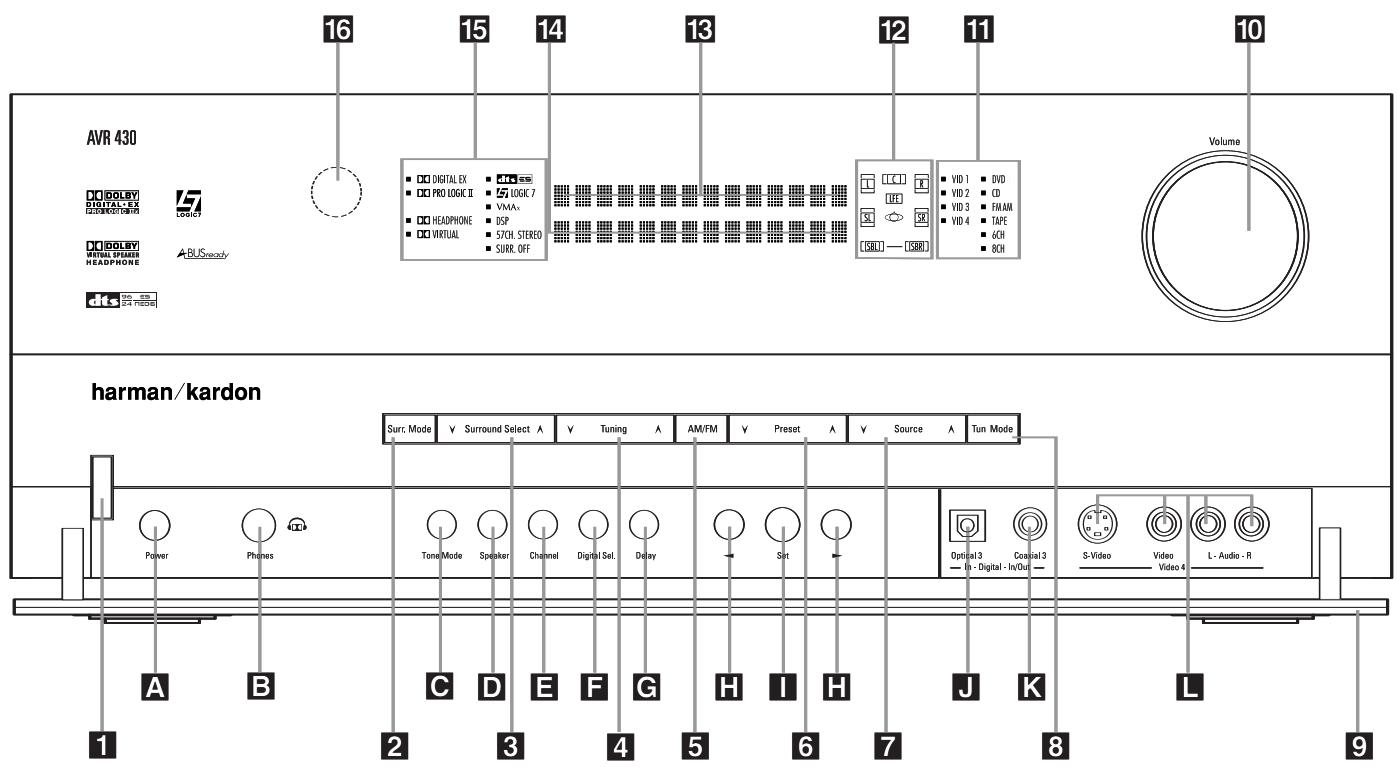
NOTE: To make it easier to follow the instructions that refer to this illustration, a larger copy may be downloaded from the Product Support section for this product at www.harmankardon.com.
The following controls and indicators are available on the AVR 430's front panel:
1 Standby/On Switch
2 Surround Mode Group Selector
3 Surround Mode Selector
4 Tuning Selector
5 Tuner Band Selector
6 Preset Station Selector
7 Input Source Selector
8 Tuning Mode Selector
9 Front Panel Control Door
10 Volume Control
11 Input Indicators
12 Speaker/Channel Input Indicators
Upper Display Line
Lower Display Line
15 Surround Mode Indicators
Remote Sensor Window
The following controls and jacks are located behind the front-panel door. To open the door, place the edge of a finger on the left or right edge of the panel and gently swing the door down towards you.
A Main Power Switch
B Headphone Jack
C Tone Mode Button
D Speaker Selector Button
Channel Adjust Selector
F Digital Input Selector
Delay Adjust Selector
H Buttons
1 Set Button
J Optical 3 Digital Input
K Coaxial 3 Digital Jack
Video 4 Audio/Video Jacks
1 Standby/On Switch: When the Main Power Switch A is "ON," press this button to turn on the AVR 430; press it again to turn the unit off. Note that the illumination surrounding the switch will turn blue when the unit is on.
2 Surround Mode Group Selector: Press this button to select the top-level group of surround modes. Each press of the button will select one of the surround mode categories. Once the button is pressed so
that the name of the desired surround mode category appears in the on-screen display and in the Lower Display Line 14, press the Surround Mode
Selector 3 to cycle through the individual modes available. For example, press this button to select Dolby modes, and then press the Surround Mode Selector
3 to choose from the various mode options.
3 Surround Mode Selector: Press this button to select from among the available surround mode
options for the surround mode category selected. The specific modes will vary based on the number of speakers available, the surround mode category and whether the input source is digital or analog. For example, press the Surround Mode Group Selector 2 to select a category such as Dolby or Logic 7, and then press this button to see the specific mode choices that are available. (For more information on mode selection, see page 31.)
4 Tuning Selector: Press the left side of the button to tune lower-frequency stations and the right side of the button to tune higher-frequency stations. When the tuner is in the MANUAL/MONO mode, each tap of the Selector will increase or decrease the frequency by one increment. When the tuner receives a strong-enough signal for adequate reception, MANUAL TUNED will appear in the Lower Display Line 14 and in the on-screen display. When the tuner is in the AUTO/STEREO mode, press the button once, and the tuner will scan for a station with acceptable signal strength. When the next higher or lower frequency station with a strong-enough signal is tuned, the frequency scan will stop and the Lower Display Line 14 and the on-screen display will indicate AUTO TUNED. When an FM Stereo station is tuned, the display will read AUTO ST TUNED. (See page 34 for more information on using the tuner.)
5 Tuner Band Selector: Pressing this button will automatically switch the AVR 430 to the Tuner mode. Pressing it again will switch between the AM and FM frequency bands. (See page 34 for more information on the tuner.)
6 Preset Station Selector: Press this button to scroll up or down through the list of stations that have been entered into the preset memory. (See page 34 for more information on tuner programming.)
7 Input Source Selector: Press this button to change the input by scrolling up or down through the list of input sources.
8 Tuning Mode Selector: Press this button to select Auto or Manual tuning. When the button is pressed so that AUTO / STEREO appears in the Upper Display Line 18, the tuner will search for the next station with an acceptable signal when the Tuning Selector 423E is pressed. When the button is pressed so that MANUAL/MONO appears in the Upper Display Line 13, each press of the Tuning Selector 423E will increase the frequency. (See page 34 for more information on using the tuner.) This button may also be used to switch between Stereo and Mono modes for FM radio reception. When weak
reception is encountered, select the Manual/Mono tuning mode. Press and hold again to switch back to Stereo mode. (See page 34 for more information on using the tuner.)
9 Front-Panel Control Door: To open the door so that the front-panel jacks and controls behind this door may be accessed, gently pull the door down and towards you using either upper corner of the door.
10 Volume Control: Turn this knob clockwise to increase the volume, counterclockwise to decrease the volume. If the AVR 430 is muted, adjusting the volume control will automatically release the unit from the silenced condition.
11 Input Indicators: One of these indicators will light to identify the currently selected input. Note that the entire list will light briefly each time the unit is turned on as a test.
12 Speaker/Channel Input Indicators: These indicators are multipurpose, indicating both the speaker type selected for each channel and the incoming data-signal configuration. The left, center, right, right surround and left surround speaker indicators are composed of three boxes, while the subwoofer is a single box. The center box lights when a "small" speaker is selected, and the two outer boxes light when "large" speakers are selected. When none of the boxes are lit for the center, surround or subwoofer channels, no speaker has been assigned that position. (See page 23 for more information on configuring speakers.) The letters inside each box displays the active input channels. For standard analog inputs, only the L and R will light, indicating a stereo input. For a digital source, the indicators will light to display the channels being received at the digital input. When the letters flash, the digital input has been interrupted. (See page 33 for more information on the Channel Indicators.)
18 Upper Display Line: Depending on the unit's status, a variety of messages will appear here. In normal operation, this line will show the current input source and identify whether an analog or digital input is in use. When the tuner is selected as the input, this line will identify the station as AM or FM and show the frequency and preset number, if any.
14 Lower Display Line: Depending on the unit's status, a variety of messages will appear here. In normal operation, the current surround mode will appear on this line.
15 Surround Mode Indicators: One of these indicators will light to show the surround mode in use. Depending on the specific combination of input sources and surround mode selected, more than one indicator may light. (See page 31 for more information.)
Remote Sensor Window: The sensor behind this window receives infrared signals from the remote control. Aim the remote at this area and do not block or cover it unless an external remote sensor is installed.
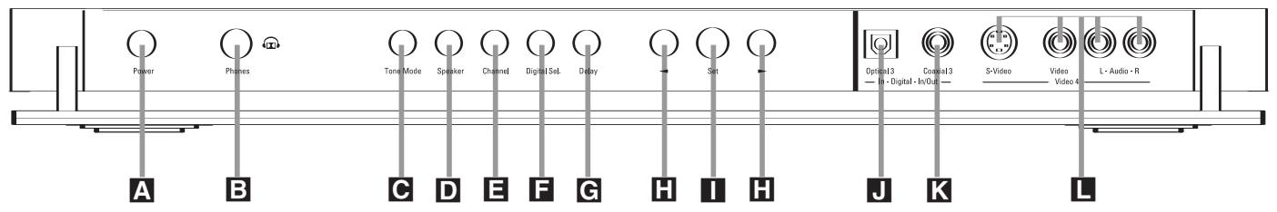
The following controls and jacks are located behind the front-panel door. To open the door, place the edge of a finger on the left or right edge of the panel and gently swing the door down towards you.
A Main Power Switch: Press this switch to apply power to the AVR 430. When the switch is pressed in, the unit is placed in a Standby mode, as indicated by the amber illumination surrounding the Standby/On Switch 1. This button MUST be pressed in to operate the unit. To turn the unit off and prevent the use of the remote control, this switch should be pressed until it pops out from the front panel so that the word "OFF" may be read at the top of the switch.
NOTE: This switch is normally left in the "ON" position.
Headphone Jack: This jack may be used to listen to the AVR 430's output through a pair of headphones. Be certain that the headphones have a standard 1/4'' stereo phone plug, or that you use an adapter, as needed, to convert the plug on your headphones to the 1/4'' jack used on the AVR. When the headphone jack is in use, the main room speakers will automatically be turned off and the unit will output a standard stereo signal. You may also use one of the Dolby Headphone modes for an enhanced listening experience. (For more information on headphone listening, see page 31.)
Tone Mode Button: This button controls the tone mode settings, enabling adjustment of the bass and treble boost/cut. You may also use it to take the tone controls out of the signal path completely for "flat" response. The first press of the button displays a TONE MODE message in the Lower Display Line 14 and in the on-screen display. To take the controls out of the signal path, press either of the Buttons H until the display reads TONE OUT. To change the bass or treble settings, press the button again until the desired option appears in the Lower Display Line 14 and in the on-screen display and then press either of the Buttons H to enter the desired boost or cut setting. (Note that the tone controls apply only to the front left/right speakers to avoid the possibility of clipping distortion in the surround channels. See pages 21 and 30 for more information on the tone controls.)
Speaker Selector Button: Press this button to begin the process of configuring the AVR 430 for the type of speakers it is being used with. For complete information on configuring the speaker settings, see page 23.
Channel Adjust Selector: Press the button to begin the process of adjusting the channel level outputs using the source currently playing through your AVR. (For complete information on adjusting the channel output level, see page 35.)
Digital Input Selector: Press this button to begin the process of selecting a digital source for use with the currently selected input. Once the button has been pressed, use the Buttons H to choose the desired input and then press the Set Button I to enter the setting into the unit's memory. (See page 31 for more information on digital audio.)
Delay Adjust Selector: Press this button to begin the process of adjusting the delay settings for Dolby surround modes. (See page 26 for more information on delay adjustments.)
H Buttons: When making system configuration changes using the front-panel controls, press these button to scroll through the available choices for the option being adjusted.
1 Set Button: When making system configuration changes using the front-panel controls, press this button to enter a setting into the unit's memory.
Optical 3 Digital Input: Connect the optical digital output of an audio or video product to this jack.
K Coaxial 3 Digital Jack: Connect the coaxial digital input or output for a digital audio product such as a portable audio player or video game to this jack.
Video 4 Jacks: These audio/video jacks may be used as an input for temporary connection to video games or portable audio/video products such as cam-corders and portable audio players.
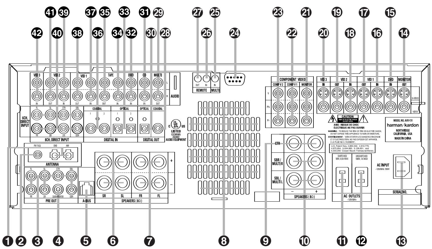
1 AM Antenna
FM Antenna
3 Preamp Outputs
4 Subwoofer Output
5 A-BUS Connector
Surround Speaker Outputs
7 Front Speaker Outputs
3 Fan Vents
9 Center Speaker Outputs
10 Surround Back/Multiroom Speaker Outputs
Switched AC Accessory Outlet
Unswitched AC Accessory Outlet
13 AC Power Cord Jack
14 Video Monitor Outputs
DVD Video Inputs
16 Video 1 Video Inputs
17 Video 1 Video Outputs
18 Video 2 Video Inputs
19 Video 2 Video Outputs
20 Video 3 Video Inputs
21 Component Video Monitor Outputs
Component Video 1 Inputs
Component Video 2 Inputs
24 RS-232 Port
25 Multiroom IR Input
Remote IR Input
Remote IR Output
Coaxial Digital Audio Output
29 Multiroom Audio Outputs
Optical Digital Audio Output
CD Audio Inputs
DVD Audio Inputs
Optical Digital Audio Inputs
34 Tape Inputs
35 Tape Outputs
36 Coaxial Digital Audio Inputs
37 Video 1 Audio Inputs
38 Video 1 Audio Outputs
39 Video 2 Audio Inputs
40 8-Channel Direct Inputs
Video 2 Audio Outputs
Video 3 Audio Inputs
NOTE: To make it easier to follow the instructions that refer to this illustration, a larger copy may be downloaded from the Product Support section for this product at www.harmankardon.com.
NOTE: To assist in making the correct connections for multichannel input, output and speaker connections, all connection jacks and terminals are color-coded in conformance with the CEA standards as follows:
Front Left: White
Front Right: Red
Center: Green
Surround Left: Blue
Surround Right: Gray
Surround Back Left: Brown
Surround Back Right: Tan
Subwoofer: Purple
Digital Audio: Orange
Composite Video: Yellow
Component Video "Y": Green
Component Video "Pr": Red
Component Video "Pb": Blue
1 AM Antenna: Connect the AM loop antenna supplied with the receiver to these terminals. If an external AM antenna is used, make connections to the AM and GND terminals in accordance with the instructions supplied with the antenna.
FM Antenna: Connect the supplied indoor or an optional external FM antenna to this terminal.
Preamp Outputs: Connect these jacks to an optional, external power amplifier for applications where higher power is desired.
4 Subwoofer Output: Connect this jack to the line-level input of a powered subwoofer. If an external subwoofer amplifier is used, connect this jack to the subwoofer amplifier input.
A-BUS Connector: Connect this jack to an optional A-BUS®-certified remote room keyboard or amplifier to extend the multiroom capabilities of your AVR 430. See page 38 for more information on A-BUS.
Surround Speaker Outputs: Connect these outputs to the matching + and - terminals on your surround channel speakers. In conformance with the CEA color-code specification, the blue terminal is the positive, or "+" terminal that should be connected to the red (+) terminal on the Surround Left speaker with older color-coding, while the gray terminal should be connected to the red (+) terminal on the Surround Right speaker with the older color-coding. Connect the black (-) terminal on the AVR to the matching black negative (-) terminals for each surround speaker. (See page 16 for more information on speaker polarity.)
7 Front Speaker Outputs: Connect these outputs to the matching + or - terminals on your left and right speakers. When making speaker connections always make certain to maintain correct polarity by connecting the color-coded (white for front left and red for front right) (+) terminals on the AVR 430 to the red (+) terminals on the speakers and the black (-) terminals on the AVR 430 to the black (-) terminals on the speakers. See page 16 for more information on speaker polarity.
Fan Vents: These ventilation holes are the output of the AVR 430's airflow system. To ensure proper operation of the unit and to avoid possible damage to delicate surfaces, make certain that these holes are not blocked and that there is at least three inches of open space between the vent holes and any wooden or fabric surface. It is normal for the fan to remain off at most normal volume levels. An automatic temperature sensor turns the fan on only when it is needed.
Center Speaker Outputs: Connect these outputs to the matching + and - terminals on your center channel speaker. In conformance with the CEA colorcode specification, the green terminal is the positive, or "+" terminal that should be connected to the red (+) terminal on speakers with the older color-coding. Connect the black (-) terminal on the AVR to the black negative (-) terminal on your speaker. (See page 16 for more information on speaker polarity.)
10 Surround Back/Multiroom Speaker Outputs: These speaker terminals are normally used to power the surround back left/surround back right speakers in a 7.1 channel system. However, they may also be used to power the speakers in a second zone, which will receive the output selected for a multiroom system. To change the output fed to these terminals from the default of the Surround Back speakers to the Multiroom Output, you must change a setting in the Advanced Menu of the OSD system. See page 39 for more information on configuring this speaker output. In normal surround system use, the brown and black terminals are the surround back left channel positive (+) and negative (-) connections and the tan and black terminals are the surround back right positive (+) and negative (-) terminals. For multiroom use, connect the brown and black SBL terminals to the red and black connections on the left remote zone speaker and connect the tan and black SBR terminals to the red and black terminals on the right remote zone speaker.
Switched AC Accessory Outlet: These outlets may be used to power any device you wish to have turned on when the AVR 430 is turned on with the Standby/On Switch 1.
1 Unswitched AC Accessory Outlet: This outlet may be used to power any AC device. The power will remain on at this outlet regardless of whether the AVR 430 is on or off.
NOTE: The total power consumption of all devices connected to the accessory outlets should not exceed 100 watts.
13 AC Power Cord Jack: Connect the AC power cord to this jack when the installation is complete. To ensure safe operation, use only the power cord supplied with the unit. If a replacement is required, it must be of the same type and capacity.
14 Video Monitor Outputs: Connect these jacks to the composite or S-Video input of a TV monitor or video projector to view the on-screen menus and the output of any standard video source selected by the receiver's video switcher.
DVD Video Inputs: Connect the composite or S-Video outputs of a DVD player or other video source to these jacks.
16 Video 1 Video Inputs: Connect the composite or S-Video PLAY/OUT jacks of a VCR or other video source to these jacks.
17 Video 1 Video Outputs: Connect the composite or S-Video REC/IN jacks of a VCR or other video recording device such as a DVD recorder or PVR to these jacks.
18 Video 2 Video Inputs: Connect the composite or S-Video PLAY/OUT jacks of a VCR or other video source to these jacks.
19 Video 2 Video Outputs: Connect the composite or S-Video REC/IN jacks of a VCR or other video recording device such as a DVD recorder or PVR to these jacks.
20 Video 3 Video Inputs: Connect the composite or S-Video PLAY/OUT jacks of a VCR or other video source to these jacks.
2 Component Video Monitor Outputs: Connect these outputs to the component video inputs of a video projector or monitor. When a source connected to one of the Component Video Inputs 2223 is selected the signal will be sent to these jacks.
2 Component Video 1 Inputs: These inputs may be used with any source device equipped with analog Y/Pr/Pb or RGB component video outputs. The factory default is for these jacks to be a linked to the DVD input, but you may change the setting at any time through the INPUT SETUP menu. (See page 21 for more information on configuring the component video inputs.)
Component Video 2 Inputs: These inputs may be used with any video source device equipped with analog Y/Pr/Pb or RGB component video outputs. The factory default is for these jacks to be a linked to the Video 2 input, but you may change the setting at any time through the INPUT SETUP menu. (See page 21 for more information on configuring the component video inputs.)
24 RS-232 Port: This jack may be used to control the AVR 430 over a bi-directional RS-232 serial control link to a compatible computer or programmable remote control system. Due to the complexity of programming RS-232 commands we strongly recommend that connections to this port for control purposes be made by a trained and qualified technician. This jack may also link to a compatible computer to upgrade the software and operating system of the AVR 430 when appropriate upgrades are available.
25 Multiroom IR Input: Connect the output of an IR sensor in a remote room to this jack to operate the AVR 430's multiroom control system.
Remote IR Input: If the AVR 430's front-panel IR sensor is blocked due to cabinet doors or other obstructions, an external IR sensor may be used. Connect the output of the sensor to this jack.
Remote IR Output: This connection permits the IR sensor in the receiver to serve other remote controlled devices. Connect this jack to the "IR IN" jack on Harman Kardon (or other compatible) equipment.
Coaxial Digital Audio Output: Connect this jack to the coaxial digital input of a CD-R/RW, MiniDisc or other compatible digital recorder.
29 Multiroom Audio Outputs: Connect these jacks to the optional external audio power amplifier and video distribution system that delivers the source selected for multizone distribution.
Optical Digital Audio Output: Connect this jack to the optical digital input connector on a CD-R/RW, MiniDisc or other compatible digital recorder.
CD Audio Inputs: Connect these jacks to the left/right analog audio output of a compact disc player or CD changer or other audio source.
DVD Audio Inputs: Connect the left/right analog outputs of a DVD player or other audio source to these jacks.
Optical Digital Audio Inputs: Connect the optical digital output from a DVD player, HDTV receiver, the S/P-DIF output of a compatible computer sound card playing MP3 files or streams, LD player or CD player to these jacks. The signal may be a Dolby Digital signal, a DTS signal or a standard PCM digital source.
34 Tape Inputs: Connect these jacks to the Play/Out jacks of an audio recorder.
35 Tape Outputs: Connect these jacks to the Record/Input jacks of an audio recorder.
Coaxial Digital Audio Inputs: Connect the coax digital output from a DVD player, HDTV receiver, the S/P-DIF output of a compatible computer sound card playing MP3 files or streams, LD player or CD player to these jacks. The signal may be a Dolby Digital signal, DTS signal or a standard PCM digital source. Do not connect the RF digital output of an LD player to these jacks.
37 Video 1 Audio Inputs: Connect the left/right PLAY/OUT audio output jacks on a VCR or other video source to these jacks.
38 Video 1 Audio Outputs: Connect the left/right REC/IN audio input jacks on a VCR or other video source to these jacks.
39 Video 2 Audio Inputs: Connect the left/right PLAY/OUT audio output jacks on a VCR or other video source to these jacks.
40 8-Channel Direct Inputs: These jacks are used for connection to source devices such as DVD-Audio or SACD players with discrete analog outputs. Depending on the source device in use, all eight jacks may be used, though in many cases only connections to the front left/right, center, surround left/right and LFE (subwoofer input) jacks will be used for standard 5.1 audio signals.
Video 2 Audio Outputs: Connect the left/right REC/IN audio input jacks on a VCR or other video source to these jacks.
Video 3 Audio Inputs: Connect the left/right PLAY/OUT audio output jacks on a VCR, PVR, cable set-top, satellite receiver, HDTV receiver or other video source to these jacks.
Power Off Button
Power On Button
LCD Information Display
4 Input Selectors
5 AVR Selector
Test Button
DSP Surround Mode Selector
Logic 7 Mode Select Button
9 Direct Button
10 Clear Button
11 Numeric Keys
12 Tuning Mode Button
Dim Button
14 Channel Select Button
15 Navigation Button
16 Digital Select Button
17 Set Button
18 Volume Up/Down Selectors
19 Transport Fast-Play/Scan Buttons
20 Main Transport Controls
21 Track Skip Up/Down Buttons
22 Preset Up/Down Button
23 Tuning Up/Down Button
24 Disc Skip Button
25 Program Button
26 Light Button
27 Multiroom Button
23 Macro Buttons
29 Sleep Button
30 Night Mode Button
31 OSD Button
32 Tone Control Button
33 Mute Button
34 AM/FM Button
35 Channel Up/Down Selector
Transport Play Buttons
37 Delay Select Button
38 Speaker Select Button
39 Memory Button
40 Stereo Mode Select Button
4DTS Neo:6 Mode Select Button
42 DTS Digital Mode Select Button
43 Dolby Mode Select Button
44 6/8-Channel Input Select
45 SPL Select Button
46 EzSet Microphone Sensor
47 Lens
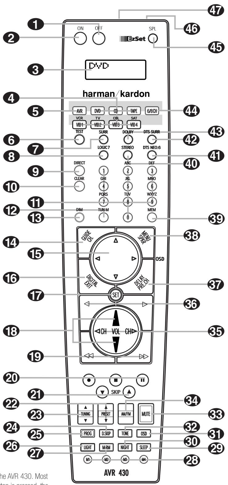
NOTES:
- The function names shown here are each button's feature when used with the AVR 430. Most buttons have additional functions when used with other devices. When a button is pressed, the function name will appear in the bottom line of the LCD Information Display ③.
- The jack on the upper right side of the remote is reserved for future use. Do not remove the plug provided or connect any device to the jack.
- To make it easier to follow the instructions that refer to this illustration, a larger copy may be downloaded from the Product Support section for this product at www.harmankardon.com.
IMPORTANT NOTE: The AVR 430's remote may be programmed to control up to eight devices, including the AVR 430. Before using the remote, it is important to remember to press the Input Selector Button that corresponds to the unit you wish to operate. In addition, the AVR 430's remote is shipped from the factory to operate the AVR 430 and most Harman Kardon CD or DVD players and cassette decks. The remote is also capable of operating a wide variety of other products using the control codes that are part of the remote. Before using the remote with other products, follow the instructions on pages 41 - 50 to program the proper codes for the products in your system.
It is also important to remember that many of the buttons on the remote take on different functions, depending on the product selected using the Input Selectors 4. The descriptions shown here primarily detail the functions of the remote when it is used to operate the AVR 430.
Power Off Button: Press this button to place the AVR 430 or a selected device in the Standby mode. Note that this will turn off the main room functions, but if the Multiroom system is activated, it will continue to function.
Power On Button: Press this button to turn on the power to a device selected by first pressing one of the Input Selectors 4
LCD Information Display: This two-line screen displays various information depending on the commands that have been entered into the remote.
4 Input Selectors: Pressing one of these buttons will perform three actions at the same time. First, if the AVR 430 is not turned on, this will power up the unit. Next, it will select the source shown on the button as the input to the AVR 430. Finally, it will change the remote control so that it controls the device selected. After pressing one of these buttons you must press the AVR Selector Button 5 again to operate the AVR 430's functions with the remote.
AVR Selector: Pressing this button will switch the remote so that it will operate the AVR 430's functions. If the AVR 430 is in the Standby mode, it will also turn the AVR 430 on.
6 Test Button: Press this button to begin the sequence used to calibrate the AVR 430's output levels. (See page 26 for more information on calibrating the AVR 430.)
DSP Surround Mode Selector: Press this button to select one of the DSP surround modes, such as VMAx, Hall 1, Hall 2 or Theater. Each press of the button selects another mode. (See page 32 for more information on surround modes.)
Logic 7 Mode Select Button: Press this button to select from among the available Logic 7 surround modes. (See page 32 for the available Logic 7 options.)
9 Direct Button: Press this button when the tuner is in use to start the sequence for direct entry of a station's frequency. After pressing the button, simply press the proper Numeric Keys 11 to select a station. (See page 34 for more information on the tuner.)
10 Clear Button: When programming the remote or using the EzSet feature, press this button to cancel the current function. When using the remote to enter frequencies for direct tuner access, press this button to clear previous entries.
Numeric Keys: These buttons serve as a ten按钮 numeric keypad to enter tuner preset positions. They are also used to select channel numbers when TV, Cable or SAT has been selected on the remote, or to select track numbers on a CD, DVD or LD player, depending on how the remote has been programmed. These buttons are also used to enter letters and numbers when renaming devices in the LCD Information Display. (See page 48 for more information on renaming devices and keys.)
12 Tuning Mode Button: Press this button to change the tuner mode between manual and automatic. When the button is pressed so that AUTO / STEREO appears in the Upper Display Line 13 and in the on-screen display, only stations with acceptable signal quality will be tuned, and the tuner will play FM stations in stereo, when available. In the AUTO mode, when the Tuning Up/Down Buttons 423E are pressed, the unit will automatically search for the next available station with good signal strength. When this button is pressed so that MANUAL/MONO appears in the Upper Display Line 13 and in the on-screen display each press of the Tuning Up/Down Buttons 423E will move the frequency up or down in single-step increments. When the FM band is in use, pressing the button so that the MANUAL mode is activated will enable you to tune stations with weak signals by changing to monaural reception. (See page 34 for more information on tuner operation.)
Dim Button: Press this button to activate the Dimmer function, which reduces the brightness of the front-panel display, or turns it off entirely. Press the button once to change the display to reduce the brightness by 50% , and press it again within five seconds and the main display will go completely dark. Note that this setting is temporary; regardless of any changes, the display will always return to full brightness when the AVR is turned on. The blue illumination around the Standby/On Switch will always remain at full brightness regardless of the setting to remind you that the AVR is still turned on. The blue accent lighting inside the volume control will go out when the panel lights are at half brightness or fully dimmed.
14 Channel Select Button: This button is used to start the process of setting the AVR 430's output levels to an external source. Once this button is pressed, press the / on the Navigation Button 15 to select the channel being adjusted, then press the Set Button 17, followed by the / on the Navigation Button 15 again, to change the level setting. (See page 35 for more information.)
Navigation Button: This single disc-like button is used to navigate through the on-screen configuration menus, to scroll through the options list and to select choices for the various settings such as delay, speakers, surround modes, digital inputs, etc. To use the button, simply press it left, right, up or down in the direction indicated by the icons printed on the button disc. Depending on the menu being used, pressing the button will either change a specific menu or configuration choice or it will change the option shown in the on-screen or front-panel display. The sections in this manual describing the unit's individual features and configuration options contain specific information on how the navigation controls are used.
16 Digital Select Button: Press this button to assign one of the digital inputs 33 36 JK to a source. (See page 33 for more information on using digital inputs.)
17 Set Button: This button is used to enter settings into the AVR 430's memory. It is also used in the setup procedures for delay time, speaker configuration and channel output level adjustment.
Volume Up/Down Buttons: These controls share the common disc in the lower third of the remote. To raise the volume, press the button marked by pressing towards the top of the remote. To lower the volume, press the button marked by pressing towards the bottom of the remote. The buttons on the left and right sides of this disc change channels up or down when the TV, cable box or satellite Input Selectors have been pressed.
19 Transport Fast-Play/Scan Buttons: These buttons have no direct function on the AVR 430, but they are used when the remote is programmed for a compatible DVD, CD or tape player. Pressing these buttons will transmit a fast-play forward, fast-play reverse, or fast-forward or -reverse scan command, according to the capabilities of the player being controlled. In the factory default setting, these buttons are preprogrammed with the remote codes for Harman Kardon DVD players so that you may control a compatible player without having to switch devices.
20 Main Transport Controls: These buttons have no direct function on the AVR 430, but they are used when the remote is programmed for a compatible DVD, CD or tape player. Pressing these buttons will transmit a stop (■), record (●), or pause (II) command, according to the capabilities of the player being controlled. In the factory default setting, these buttons are programmed with the remote codes for Harman Kardon DVD players so that you may control a compatible player without having to switch devices.
21 Track Skip Up/Down Buttons: These buttons do not have a direct function with the AVR 430, but when used with a compatibly programmed CD or DVD changer will change the track or chapter currently being played. In the factory default setting, these buttons are programmed with the remote codes for Harman Kardon DVD players so that you may control a compatible player without having to switch devices.
22 Preset Up/Down Button: When the tuner is in use, press this button to scroll through the stations programmed into the AVR 430's memory.
28 Tuning Up/Down Button: Press this button when the tuner is in use to change the station to one with a higher or lower frequency. When the tuner is in the MANUAL/MONO mode, each tap of the Selector will increase or decrease the frequency by one increment. When the tuner receives a strong-enough signal for adequate reception, MANUAL TUNED will appear in the Lower Display Line 14 and in the on-screen display. When the tuner is in the AUTO/STEREO mode, press the button once, and the tuner will scan for a station with acceptable signal strength. When the next higher- or lower-frequency station with a strong enough signal is tuned, the frequency scan will stop and the Lower Display Line 14 and the on-screen display will indicate AUTO TUNED. When an FM Stereo station is tuned, the display will read AUTO ST TUNED. (See page 34 for more information on using the tuner.)
24 Disc Skip Button: This button has no direct function for the AVR 430 but may be used to change the disc in a CD or DVD changer when the remote is programmed for that type of device.
25 Program Button: This button is used to begin the process of programming the remote. Press and hold this button for three seconds to place the remote in the programming mode. Once the red LED under the Set Button 17 lights, release the button. You may then select from the desired option. (See pages 41 - 50 for more information on configuring the remote.)
26 Light Button: Press this button to activate the remote's backlight for ease of use in darkened rooms.
27 Multiroom Button: Press this button to begin the process of activating the multiroom system or to change the input or volume level for the second zone. (See page 39 for more information on the multiroom system.)
23 Macro Buttons: Press these buttons to store or recall a "Macro", which is a preprogrammed sequence of commands stored in the remote. (See page 44 for more information on macros.)
29 Sleep Button: Press this button to place the unit in the Sleep mode. After the time shown in the display, the AVR 430 will automatically go into the Standby mode. Each press of the button changes the time until turn-off in the following order:
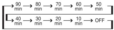
When the Sleep timer is in use the front panel displays indicators will dim to half brightness.
30 Night Mode Button: Press this button to activate the Night mode. This mode is available in specially encoded Dolby Digital sources, and it preserves dialogue (center channel) intelligibility at low volume levels.
31 OSD Button: Press this button to activate or turn off the On-Screen Display (OSD) system used to set up or adjust the AVR 430's parameters.
32 Tone Control Button: This button controls the tone mode settings, enabling adjustment of the bass and treble boost/cut. You may also use it to take the tone controls out of the signal path completely for "flat" response. The first press of the button displays a
TONE IN message in the Lower Display Line 14 and in the on-screen display. To take the controls out of the signal path press either of the
Navigation Buttons 15 until the display reads TONE OUT. To change the bass or treble settings, press the button again until the desired option appears in the Lower Display Line 14 and in the on-screen display and then press either of the /
Navigation Buttons 15 to enter the desired boost or cut setting. (See pages 21 and 30 for more information on the tone controls.)
33 Mute Button: Press this button to momentarily silence the AVR 430 or TV set being controlled, depending on which device has been selected.
34 AM/FM Button: Press this button to select the AVR 430's tuner as the listening choice. Pressing this button when the tuner is already in use will select between the AM and FM bands.
35 Channel Up/Down Selector: This button has no function when the AVR is being controlled, but when programmed for use with a VCR, TV, cable box, satellite receiver or other similar product it will change the channel up or down. (See pages 41 - 50 for more information on programming the remote.)
36 Transport Play Buttons: These buttons have no direct function on the AVR 430, but they are used when the remote is programmed for a compatible DVD, CD or tape player. Pressing these buttons will transmit a forward- or reverse-play command, according to the capabilities of the player being controlled. In the factory default setting, these buttons are programmed for Harman Kardon DVD players so that you may control a compatible player without having to switch devices.
Delay Select Button: This button selects adjustments to the A/V Sync Delay and the individual channel displays. The first press of the button displays an A/V SYNC DELAY message in the Lower Display Line 14 and in the on-screen display, which means that you may change the amount of time that all channels are delayed together behind the video. This enables you to compensate for the loss of lip sync that may be caused by digital video processing in your display or by television stations. To change the A/V Sync Delay, press the Set Button 17 while the A/V SYNC DELAY message is visible and then use the Navigation Button 15 to change the setting so that the sound and the video image are in sync. To change the delay for an individual output channel, press the Navigation Button 15 until the desired channel name is shown, and then press the Set Button 17. Use the Navigation Buttons 15 to change the delay amount. (See page 26 for more information on delay options.)
38 Speaker Select Button: Press this button to begin the process of configuring the AVR 430's bass management system. Then press the / Navigation Button 15 to select the channel you wish to set up. Press the Set Button 17 and then select another channel to configure. When all adjustments have been completed, press the Set Button 17 twice to exit the settings and return to normal operation. (See page 23 for more information on speaker setup.)
39 Memory Button: Press this button to enter a radio station to the AVR 430's preset memory. First, tune the desired station, and then press this button. Within five seconds of when you see the station's frequency flash in the Upper Display Line 13 and in the on-screen display, press the numeric keys for the preset number between 01 and 30 that you wish to assign to the station. (See page 34 for more information.)
40 Stereo Mode Select Button: Press this button to select a stereo listening mode. When the button is pressed so that SURROUND OFF appears in the Lower Display Line 14, the AVR will operate in either a bypass mode with true, fully analog, two-channel left/right stereo mode with no surround processing or with full bass management, as opposed to other modes where digital processing is always used. When the button is pressed so that SURROUND OFF appears in the Lower Display Line 14, and the DSP and SURROUND OFF Surround Mode Indicators 15 are lit, you will enjoy a two-channel presentation of the sound along with the benefits of bass management. Depending on whether your system is configured for 5.1 or 6.1/7.1 channels, the next press of the button will cause either
5 CH STEREO or 7 CH STEREO to appear, and the stereo signal will be routed to all five (or seven) speakers. (See page 32 for more information on stereo playback modes.)
4 DTS Neo:6 Mode Select Button: Press this button to select a DTS Neo:6 mode. (See page 32 for the available DTS Neo:6 options.)
42 DTS Digital Mode Select Button: When a DTS-encoded digital source is playing, each press of this button will scroll through the available DTS modes. The specific choice of modes will vary according to the type of encoding on the disc and your system's speaker configuration. When a DTS source is not in use, this button has no function. (See page 32 for the available DTS digital options.)
43 Dolby Mode Select Button: This button is used to select from the available Dolby Surround modes. Each press of this button will select one of the Dolby Pro Logic II modes or Dolby 3 Stereo. When a Dolby Digital-encoded source is in use, the Dolby Digital mode may also be selected. (See page 32 for the available Dolby surround mode options.)
44 6-Channel/8-Channel Input Select: Press this button to select the device connected to the 6- or 8- Channel Direct Inputs (See page 30 for more information.)
45 SPL Select Button: This button activates the EzSet function to quickly and accurately calibrate the AVR 430's output levels. When the button is pressed you will then need to select between automatic EzSet operation or using the remote as a manual SPL meter by pressing the Navigation Button until your choice appears in the remote's LCD display. Press the Set Button to enter the setting, and then follow the instructions as displayed in the LCD display. (For complete information, see page 27.)
46 EzSet Microphone Sensor: The microphone sensor that is used by the EzSet system is behind the three slots at the top of the remote control. When using EzSet to calibrate the AVR 430, be certain that the slots are not covered. (See page 27 for more information on using EzSet.)
47 Lens: The infrared emitters behind the plastic lens at the top of the remote communicate the remote codes to the AVR 430. Be certain that the lens is not covered when using the remote, and point the lens toward the AVR for best results. In learning mode, the remote receives IR codes to be learned through a sensor behind the lens.
NOTE: DO NOT remove the rubber plug that is supplied to cover the jack on the upper right side of the remote. The jack is not active and is reserved for future use.
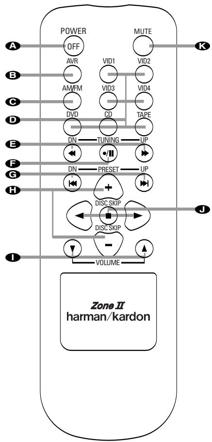
A Power Off Button
AVR Selector Button
AM/FM Tuner Selector
Input Selectors
Tuning Up/Down - Fast Play Buttons
F Record/Pause Button
G Preset Up/Down - Track Skip Buttons
Disc Skip Buttons
Volume Up/Down Buttons
Play Forward/Reverse/Stop Buttons
Mute Button
Power Off Button: When used in the room where the AVR 430 is located, press this button to place the unit in Standby. When it is used in a remote room with a sensor that is connected to the
Multiroom IR Input 25 jack, this button turns the Multiroom system on and off.
AVR Selector Button: Press this button to turn on the AVR 430. The input in use when the unit was last on will be selected.
AM/FM Tuner Selector: Press this button to select the Tuner as the input to the Multiroom system. Press it again to change between the AM and FM bands.
Input Selectors: When the AVR 430 is off, press one of these buttons to select a specific input and turn the unit on. When the unit is already in use, pressing one of these buttons will change the input.
Tuning Up/Down - Fast Play Buttons: When the Zone ll remote is used in the same room as the AVR 430, these buttons may be used to change the frequency of the tuner. These buttons may also control the Fast Play or Fast Reverse functions of compatible Harman Kardon CD, DVD or cassette decks in the same room, or from a remote room when an IR link is connected to the AVR 430.
F Record/Pause Button: Press this button to activate the Record or Pause function on compatible Harman Kardon CD, DVD or cassette deck products.
Preset Up/Down - Track Skip Buttons: When the AVR 430's tuner is selected as the input source, these buttons will move up or down through the list of stations that have been stored in the preset memory. When a CD or DVD changer or player is selected, these buttons activate the Forward or Reverse Track or Chapter Skip functions.
Disc Skip Buttons: Press these buttons to change discs on compatible Harman Kardon CD or DVD changer or players.
Volume Up/Down Buttons: When the Zone II remote is used in the room where the AVR 430 is located, press this button to raise or lower the volume in that room. When it is used in a remote room with a sensor that is connected to the Multiroom IR Input jack, this button will raise or lower the volume in the remote room.
Play Forward/Reverse/Stop Buttons: Press these buttons to control compatible Harman Kardon CD, DVD or cassette players.
Mute Button: When the Zone II remote is used in the room where the AVR 430 is located, press this button to temporarily silence the unit. When it is used in a remote room with a sensor that is connected to the Multiroom IR Input jack, this button will temporarily silence the feed to the remote room only. Press the button again to return to the previous volume level.
NOTES:
- The Zone II remote may be used in either the same room where the AVR 430 is located, or it may be used in a separate room with an optional infrared sensor that is connected to the AVR 430's Multiroom IR Input 25 jack. When it is used in the same room as the AVR 430, it will control the functions of the AVR 430 or any compatible Harman Kardon products in that room. When it is used in a separate room via a sensor connected to the Multiroom IR Input 25 jack, the buttons for Power, Input Source, Volume and Mute will control the source and volume for the second zone, as connected to the Multiroom Audio Outputs 25 jacks. (See page 39 for complete information on using the Multiroom system.)
- To make it easier to follow the instructions that refer to the controls and connectors in this illustration, a larger copy may be downloaded from the Product Support section for this product at www.harmankardon.com.
System Installation
After unpacking the unit, locating it in a place with adequate ventilation and placing it on a solid surface capable of supporting its weight, you will need to make the connections to your audio and video equipment.
IMPORTANT NOTE: For your personal safety and to avoid possible damage to your equipment and speakers, it is always good practice to turn off and unplug the AVR and ALL source equipment from the AC output before making any audio or video system connections.
Audio Equipment Connections
We recommend that you use high-quality interconnect cables when making connections to source equipment and recorders to preserve the integrity of the signals.
- Connect the analog output of a CD player to the CD Audio Inputs 31.
NOTE: If your CD player has both fixed and variable audio outputs, it is best to use the fixed output unless you find that the input to the receiver is so low that the sound is noisy, or so high that it is distorted. - Connect the analog Play/Out jacks of a cassette deck, MD, CD-R or other audio recorder to the Tape Inputs 34. Connect the analog Record/In jacks on the recorder to the Tape Outputs 35 on the AVR 430.
- Connect the output of any digital sources such as such as a CD or DVD changer or player, advanced video game, a digital satellite receiver, HDTV tuner or digital cable set-top box or the output of a compatible computer sound card to the Optical and Coaxial Digital Audio Inputs 33 36 JJK.
- Connect the coaxial or optical Digital Audio Outputs 2630 on the rear panel of the AVR 430 to the matching digital input connections on a CD-R or MiniDisc recorder.
- Assemble the AM loop antenna supplied with the unit so that the tabs at the bottom of the antenna loop snap into the holes in the base. Connect it to the AM and GND Screw Terminals 1

-
Connect the supplied FM antenna to the FM (75-Ohm) Connection ② . The FM antenna may be an external roof antenna, an inside powered or wire-lead antenna or a connection from a cable TV system. If the antenna or connection uses 300-ohm twin-lead cable, you must use an optional 300-ohm-to-75-ohm adapter to make the connection.
-
Connect the front, center, surround and surround back speaker outputs 67910 to the respective speakers.
To ensure that all the audio signals are carried to your speakers without loss of clarity or resolution, we suggest that you use high-quality speaker cable. Many brands of cable are available and the choice of cable may be influenced by the distance between your speakers and the receiver, the type of speakers you use, personal preferences and other factors. Your dealer or installer is a valuable resource to consult in selecting the proper cable.
Regardless of the brand of cable selected, we recommend that you use cable with a gauge of 14 or smaller. Remember that in specifying cable, the lower the number, the thicker the cable.
Cable with a gauge of 16 may be used for short runs of less than ten feet. We do not recommend that you use cables with an AWG equivalent of 18 or higher, due to the power loss and degradation in performance that will occur.
Cables that are run inside walls should have the appropriate markings to indicate listing with UL, CSA or other appropriate testing agency standards. Questions about running cables inside walls should be referred to your installer or a licensed electrician who is familiar with the NEC and/or the applicable building codes in your area.
When connecting wires to the speakers, be certain to observe proper polarity. Note that the positive (+) terminal of each speaker connection now carries a specific color code, as noted on page 8. However, most speakers still use a red terminal for the positive (+) connection. Connect the "negative" or "black" wire to the same terminal on both the receiver and the speaker.
NOTE: While most speaker manufacturers adhere to an industry convention of using black terminals for negative and red ones for positive, some may vary from this configuration. To ensure proper phase and optimal performance, consult the identification plate on your speaker or the speaker's manual to verify polarity. If you do not know the polarity of your speaker, ask your dealer for advice before proceeding, or consult the speaker's manufacturer.
We also recommend that the length of cable used to connect speaker pairs be identical. For example, use the same length piece of cable to connect the front-left and front-right or surround-left and surround-right speakers, even if the speakers are a different distance from the AVR 430.
- Connections to a subwoofer are normally made via a line-level audio connection from the Subwoofer Output 4 to the line-level input of a subwoofer with a built-in amplifier. When a passive subwoofer is used, the connection first goes to a power amplifier, which will be connected to one or more subwoofer speakers. If you are using a powered subwoofer that does not have line-level input connections, follow the instructions furnished with the speaker for connection information.
- If an external multichannel audio source with 5.1 outputs such as an external digital processor/decoder, DVD-Audio or SACD player is used, connect the outputs of that device to the 8-Channel Direct Inputs 40 .
Video Equipment Connections
Video equipment is connected in the same manner as audio components. Again, the use of high-quality interconnect cables is recommended to preserve signal quality.
- Connect a VCR's or other video source's audio and video Play/Out jacks to the Video 1/Video 2 Audio and Video Input Jacks 16183739 on the rear panel. The Audio and Video Record/In jacks on the VCR should be connected to the Video 1/Video 2 Audio and Video Output Jacks 17193841 on the AVR 430.
- Connect the analog audio and video outputs of a satellite receiver, cable TV converter or television set or any other video source to the Video 3 Audio and Video Input Jacks 2042
- Connect the analog audio and video outputs of a DVD or laser disc player to the DVD Audio and Video Inputs 15 32
- Connect the optical or coaxial digital audio outputs of a DVD player, satellite receiver, cable box, HDTV tuner or video game to any of the Optical or Coaxial Digital Inputs 33 36 JK. The recommended connection for a DVD player is to use a Coaxial digital link connected to the Coaxial Digital Audio Input 1, but you may change the digital audio input assignment for any source using the INPUT SETUP menu as described on page 21 or the Digital Input Selector F16 on the front panel or remote, as described on page 33.
NOTE: When connecting a device such as a digital cable box or other set-top tuner product with a digital audio output, we recommend that you connect both the digital and analog outputs of the product to your AVR. The audio input polling feature of the AVR will then be able to make certain that you have a constant audio feed, since it will automatically switch the audio input to the analog jacks if the digital feed is interrupted or not available for a particular channel.
-
Connect the Video Monitor Output 14 jacks on the receiver to the composite or S-Video input of your television monitor or video projector.
-
If your DVD Player has Y/Pr/Pb analog component video outputs, connect them to the Component Video 1 Inputs . Although this set of inputs may be assigned to any of the four video inputs on the AVR 430, the factory default is for this input to be assigned to the DVD Audio Inputs . Remember to make a digital audio connection between the DVD player and the AVR, with the Coaxial Digital Input 1 36 being the factory default. For information on changing the input assignments for either the component video jacks or the DVD player's audio connection, see page 20.
-
If you have other devices with Y/Pr/Pb or RGB component video outputs, connect the source device to the Component Video 2 Inputs 23. The audio connections may be to any of the Video Audio Inputs 37 39 42 L or the Optical or Coaxial Digital Inputs 33 36 JK. When using either of the Component Video Inputs, make certain that the audio and video inputs are properly configured in the INPUT SETUP menu, as described on page 20.
-
If the component video inputs are used, connect the Component Video Monitor Outputs 2 to the component video inputs of your TV, projector or display device.
-
If you have a camcorder, video game or other audio/video device that is connected to the AVR on a temporary, rather than permanent, basis, connect the audio, video and digital audio outputs of that device to the Front-Panel Inputs JKL. A device connected here is selected as the Video 4 input, and the digital inputs must be assigned to the Video 4 input. (See page 20 for more information on input configuration.)
Video Connection Notes:
- When the component video jacks are used, the on-screen menus are not visible and you must switch to the standard composite or S-Video input on your TV to view them.
- The AVR 430 will accept either standard composite, S-Video or Y/Pr/Pb component video signals. However, it will not convert composite or S signals to component video.
- Component or composite video signals may only be viewed in their native formats.
System and Power Connections
The AVR 430 is designed for flexible use with multi-room systems, external control components and power amplifiers.
Main Room Remote Control Extension
If the receiver is placed behind a solid or smoked glass cabinet door, the obstruction may prevent the remote sensor from receiving commands. In this event, an optional remote sensor may be used. Connect the output of the remote sensor to the Remote IR Input 26 jack.
If other components are also prevented from receiving remote commands, only one sensor is needed. Simply use this unit's sensor or a remote eye by running a connection from the Remote IR Output 27 jack to the Remote IR Input jack on Harman Kardon or other compatible equipment.
Multiroom IR Link
The remote room IR receiver should be connected to the AVR 430 via standard coaxial cable. Plug the IR connection cable into the Multiroom IR Input 25 jack on the AVR 430's rear panel.
If other Harman Kardon compatible source equipment is part of the main room installation, the Remote IR Output 21 jack on the rear panel should be connected to the IR IN jack on source equipment. This will enable the remote room location to control source equipment functions.
NOTE: All remotely controlled components must be linked together in a "daisy chain". Connect the IR OUT jack of one unit to the IR IN of the next to establish this chain.
Multiroom Connections
The AVR 430 is equipped with multizone capabilities that allow it to send a separate audio source to the remote zone from the one selected for use in the main room.
Depending on your system's requirement, three options are available for audio connection:
Option 1: Use high-quality, shielded audio interconnect cable from the AVR 430's location to the remote room. In the remote room, connect the interconnect cable to a stereo power amplifier. The amplifier will be connected to the room's speakers. At the AVR 430, plug the audio interconnect cables into the Multiroom Audio Outputs on the AVR 430's rear panel.
Option 2: Connect the Multiroom Audio Outputs
29 on the AVR 430 to the inputs of an optional stereo power amplifier. Run high-quality speaker wire from the amplifier to the speakers in the remote room.
Option 3: Taking advantage of the AVR 430's built-in seven-channel amplifier, it is possible to use two of the amplifier channels to power speakers in the remote room. When using this option you will not be able to use the full 7.1-channel capabilities of the AVR 430 in the main listening room, but you will be able to add another listening room without external power amplifiers. To use the internal amplifiers to power a remote zone, connect the speakers for the remote room location to the Surround Back/Multiroom Speaker Outputs 10. Before using the remote room you will need to configure the amplifiers for surround operation by changing a setting in the Multiroom menu, following the instructions shown on page 39.
NOTE: For all options, you may connect an optional IR sensor in the remote room to the AVR 430 via an appropriate cable. Connect the sensor's cable to the Multiroom IR Input on the AVR 430 and use the Zone II remote to control the room volume. Alternatively, you may install an optional volume control between the output of the amplifiers and the speakers.
A-BUS® Installation Connections
The AVR 430 is among the very few receivers available today that offer built-in A-BUS Ready operation. When used with an optional A-BUS keypad or control module, you have all the benefits of remote zone operation without the need for an external power amplifier.
To use the AVR 430 with an approved A-BUS product, simply connect the keypad or module that is in the remote room to the AVR 430 using standard Category 5 wiring that is properly rated for the in-wall use specific to the installation. Terminate the wiring at the receiver end to a standard RJ-45 connector in compliance with the instructions furnished with the A-BUS module.
No further installation or adjustment is needed, as the A-BUS jack on the AVR 430 routes the signals in and out of the keypad to their proper destination for power, signal source and control. The output fed to the A-BUS jack is determined by the AVR 430's multiroom system and menus.
Note that the AVR 430's Multiroom system must be turned on for any product connected to the A-BUS
Connector 5 to operate. See pages 39 and 40 for more information on the Multiroom system and A-BUS.
RS-232 Connections
The AVR 430 is equipped with an RS-232 Serial Connection Port that may be used for two purposes. When the port is connected to a compatible, optional, external computer, keypad or control system the AVR 430 is capable of bi-directional communications that enable the external system to control the AVR, and for the AVR to report status and handshake data back to the controller. Use of the RS-232 port for this type of control requires specific technical knowledge, and we recommend that any connection and programming for control be made by a trained installer or technician familiar with the equipment being used.
The RS-232 port may also be used as an access point through which the AVR 430's operating system and surround mode memories may be updated via connection to a compatible computer. At the time that any upgrade is available, instructions for making the connection and installing the upgrade will be available through the Product Support area of the Harman Kardon Web site at harmankardon.com.
The physical connection to the AVR 430's RS-232 port is a standard D-SUB 9 connection but to assure compatible and proper operation, specific software commands and pin-wiring schemes may be required.
AC Power Connections
This unit is equipped with two accessory AC outlets. They may be used to power accessory devices, but they should not be used with high-current draw equipment such as power amplifiers. The total power draw to each outlet may not exceed 100 watts.
The Switched AC Accessory Outlet is powered only when the unit is on. This is recommended for devices that have a mechanical power switch that may be left in the "ON" position.
NOTE: Many audio and video products go into a Standby mode when they are used with switched outlets. This type of product may not operate properly when used with the switched outlet.
The Unswitched AC Accessory Outlet 1 is powered as long as the AVR is plugged into a powered AC outlet.
The AVR 430 features a removable power cord that allows wires to be run in advance to a complex installation so that the unit itself need not be installed until it is ready for connection. When all needed connections have been made, connect the AC Power cord to the AC Power Cord Jack 13.
The AVR 430 draws significantly more current than other household devices, such as computers, that use removable power cords. For that reason, it is important that only the cord supplied with the unit (or a direct replacement of identical capacity) be used.
Once the power cord is connected, you are almost ready to enjoy the AVR 430's incredible power and fidelity!
When all audio, video and system connections have been made, there are a few configuration adjustments that must be made. A few minutes spent to correctly configure and calibrate the unit will greatly add to your listening experience.
Speaker Selection and Placement
The placement of speakers in a multichannel home theater system can have a noticeable impact on the quality of sound reproduced.
No matter which type or brand of speakers is used, the same model or brand of speaker should be used for the left front, center and right front speakers. This creates a seamless front soundstage and eliminates the possibility of distracting sonic disturbances that occur when a sound moves across mismatched front-channel speakers.
Speaker Placement
Depending on the type of center channel speaker in use and your viewing device, place the center speaker either directly above or below your TV, or in the center behind a perforated front-projection screen.
Once the center channel speaker is installed, position the front left and front right speakers so that they are as far away from one another as the center channel speaker is from the preferred listening position. Ideally, the front channel speakers should be placed so that their tweeters are no more than 24" above or below the tweeter in the center channel speaker.
Depending on the specifics of your room acoustics and the type of speakers in use, you may find that imaging is improved by moving the left front and right front speakers slightly forward of the center channel speaker. If possible, adjust all front loudspeakers so that they are aimed at ear height when you are seated in the listening position.
Using these guidelines, you'll find that it takes some experimentation to find the correct location for the front speakers in your particular installation. Don't be afraid to move things around until the system sounds correct. Optimize your speakers so that audio transitions across the front of the room sound smooth, and that sounds from all speakers appear to arrive at the listening position at the same time (without delay from the center speaker compared to the left and right speakers).
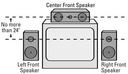
A) Front-channel speaker installation with direct-view TV sets or rear-screen projectors.
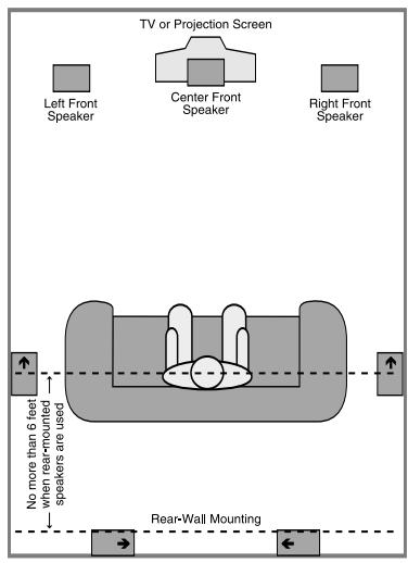
B) Rear speaker mounting is an alternate location for 5.1 systems. It is required for 7.1 operation.
When the AVR 430 is used in 5.1-channel operation, the preferred location for surround speakers is on the side walls of the room, no more than 10 degrees off axis from the listening position. In a 7.1-channel system, both side surround and back surround speakers are required. The center of the speaker should face into the room.
Rear surround speakers are required when a full 7.1-channel system is installed, and they may also be used in 5.1-channel systems as an alternative mounting position when it is not practical to place the main surround speakers on the sides of the room. Speakers may be placed on a rear wall, behind the listening position. When placing surround speakers, it is recommended that they be located so that none of the speakers is more than two feet higher than the other.
If dipole-type speakers are used on either the side or rear walls of the room, please note that if there are arrows on the speakers they should face the front of the room for the side speakers, or toward the center of the wall for the rear speakers.
Subwoofer produces nondirectional sound, so they may be placed almost anywhere in a room. Actual placement should be based on room size and shape and the type of subwoofer used. One method of finding the optimal location for a subwoofer is to begin by placing it in the front of the room, about six inches from a wall, or near the front corner of the room. Another method is to temporarily place the subwoofer at your normal listening position, and then walk around the room until you find a spot where the subwoofer sounds best. Place the subwoofer in that spot. You should also follow the instructions of the subwoofer's manufacturer, or you may wish to experiment with the best location for a subwoofer in your listening room.
System Setup
Once the speakers have been placed in the room and connected, the remaining steps in the setup process are to assign input and output connections, make any tone adjustments, select a surround mode, program the AVR 430's bass management system for the type of speakers used in your system, calibrate the output levels and set the delay times used by the surround sound processor.
You are now ready to power up the AVR 430 to begin these final adjustments.
- Make certain that the AC power cord is firmly inserted in to the AC Power Cord Jack 13 and plug the cord into an unswitched AC outlet. To maintain the unit's safety rating, DO NOT substitute the power cord for one with lower current capacity.
-
Press the Main Power Switch A located behind the Front Panel Control Door 9 in until it latches and the word "OFF" on the top of the switch disappears inside the front panel. Note that the illumination around the Standby/On Switch 1 will turn amber, indicating that the unit is in the Standby mode.
-
Carefully remove the protective plastic film from the front-panel lens. If left in place, the film will prevent proper operation of the remote control.
- Install the four supplied AAA batteries in the remote as shown. Be certain to follow the (+) and (-) polarity indicators that are in the battery compartment.
- Turn the AVR 430 on either by pressing the Standby/On Switch 1 on the front panel, or via the remote by pressing the Power On Button 2, the AVR Selector 5 B or any of the Input Selectors 4 34 44 C D on the remote. The lighting around the Standby/On Switch 1 will turn blue to confirm that the unit is on.
Using the On-Screen Display
When making the following adjustments, you may find it easier to use the AVR 430's on-screen display system. These easy-to-read displays give you a clear picture of the current status of the unit and make it easy to see which speaker, delay, input or digital selection you are making.
To view the on-screen menus, make certain you have made a connection from the Video Monitor Out Jack 14 on the rear panel to the composite or S-Video input of your TV or projector. In order to view the AVR 430's displays, the correct video source must be selected on the video display. The on-screen menus are not available when a component video display is in use.
IMPORTANT NOTE: When viewing the on-screen menus using a CRT-based projector, plasma display or direct-view CRT monitor or television, it is important that they not be left on for an extended period of time. The constant display of a static image such as these menus may cause the image to be permanently "burned into" the projection tubes, plasma screen or CRT. This type of damage is not covered by the AVR 430 warranty and may not be covered by the projector/TV set's warranty.
The AVR 430 has two on-screen display modes, "Semi-OSD" and "Full-OSD." When making configuration adjustments, it is recommended that the full-OSD mode be used. This will place an easily viewed list of the available options on the screen.
Making Configuration Adjustments
The full-OSD system is available by pressing the OSD Button 31. When this button is pressed, the MASTER MENU (Figure 1) will appear, and adjustments are made from the individual menus.
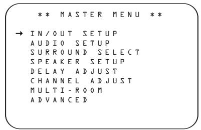
Figure 1
The semi-OSD system is also available, allowing you to make adjustments directly, by pressing the appropriate buttons on the front panel or remote control for the specific parameter to be adjusted. For example, to change the digital input for any of the sources, press the Digital Select Button 16 and then press the
/ Navigation Button 15 to scroll through the list of options as they appear in the on-screen display or in the Lower Display Line 14.
To use the full-OSD menu system, press the OSD Button 31. When the menu is on the screen, press the / Navigation Button 15 until the on-screen cursor is next to the item you wish to adjust, and then press the Set Button 17 to adjust that item. The menus will remain on the screen for 20 seconds, and then they will "time-out" and disappear from the screen. The time-out may be increased to as much as 50 seconds by going to the ADVANCED
SELECT menu, and changing the item titled FULL OSD TIME OUT.
When the full-OSD system is in use, the menu selections are not shown in the Upper or Lower Display Lines 1314. When the full-OSD menu system is used, OSD ON will appear in the Upper Display Line 18 to remind you that a video display must be used. When the semi-OSD system is used in conjunction with the discrete configuration buttons, the on-screen display will show a single line of text with the current menu selection. That selection will also be shown in the Upper or Lower Display Lines 1314 depending on which parameter is being adjusted.
Setting the System Configuration Memory
The AVR 430 features an advanced memory system that enables you to establish different configurations for the speaker "size," component video assignment, digital input, surround mode and crossover frequency for each input source. This flexibility enables you to custom-tailor the way in which you listen to each
source and have the AVR 430 memorize those settings. This means, for example, that you may set different speaker configurations with the resultant changes to the bass management system. Once these settings are made, they will automatically be recalled whenever you select that input.
The factory default settings for the AVR 430 have all inputs except for DVD and Video 3 configured for an analog audio input, the Coaxial Digital Audio Input 1 36 for DVD and the Optical Digital Input 1 33 is the default for Video 3. The default speaker settings are "Small" at all positions, with the Subwoofer on. The default setting for the surround modes is Logic 7 Music for analog sources. Dolby Digital or DTS will automatically be selected as appropriate when a digital source is in use.
Before using the unit, you may want to change the settings for some inputs so that they are properly configured to reflect the use of digital or analog inputs, the type of speakers installed and the surround mode specifics of your home theater system. Remember that since the AVR 430 memorizes the settings for each input individually, you will need to make these adjustments for each input used. However, once they are made, further adjustment is only required when system components are changed.
To make this process as quick and as easy as possible, we suggest that you use the full-OSD system with the on-screen menus, and step through each input. Once you have completed the settings for the first input, many settings may be duplicated for the remaining inputs. It is also a good idea to set the configuration data in the order these items are listed in the MASTER MENU, as some settings require a specific entry in a prior menu item.
Input Setup
The first step is to configure each input. Once an input is selected, the settings for the Digital Input, Component Video assignment and Surround Mode will "attach" themselves to that input and be stored in a nonvolatile memory. This means that once made, the selection of an input will automatically recall those settings. For that reason, the procedures described below must be repeated for each input source so that you have the opportunity to custom tailor each source to your specific listening requirements. However, once made they need not be changed again unless you need to alter a setting. The configuration settings for speaker "size" and crossover points may either be set once and applied to all inputs, or you may select a different speaker configuration for each input using the INDEPENDENT setting, as described on page 25.
When using the full-OSD system to make the setup adjustments, press the OSD Button 31 once so that the MASTER MENU (Figure 1) appears. The
cursor will be next to the INPUT SETUP line. Press the Set Button 17 and the INPUT SETUP menu (Figure 2) will appear on the screen.
Press the Navigation Button until the desired input name appears in the highlighted video, as well as being indicated in the front-panel Input Indicators. When you are scrolling through the list of available inputs you will hear a slight click from time to time. This is normal, as it is caused by the relay that is used to switch between the two Component Video Inputs.
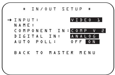
Figure 2
When one of the four Video inputs is selected as the source, you have the option of renaming the input as it appears in the on-screen and front panel messages. This is helpful if you have more than one VCR, if you wish to associate a specific product brand name with the input, or to simply enter any name that will help you to remember which source is being selected.
To change the input name, press the / Navigation Button 15 on the remote so that the cursor is pointing to NAME. Next, press and hold the Set Button 17 for a few seconds until a flashing box appears to the right of the colon. Immediately release the Set Button 17, as you are now ready to enter the device name.
Press the Navigation Button 15 and note that a complete set of alpha-numeric characters will appear with the start of the alphabet in capital letters followed by the lower-case letters and then numbers and symbols. When you press the Navigation Button 15, a series of symbols and numbers will appear, followed by a reverse list of the alphabet in lower-case letters. Press the button either way until the first letter of the desired name appears. If you wish to enter a blank space as the first character, press the Navigation Button 15.
When the desired character appears, press the Navigation Button 15 and repeat the process for the next letter, and continue until the desired name is entered, up to a maximum of fourteen characters.
Press the Set Button 17 to enter the input name into the system memory and to proceed with the configuration process.
If your system includes any sources that are equipped with Y/Pr/Pb component video outputs, the AVR 430 is able to switch them to send the proper signals to your video display. Each of the two Component Video Inputs may be assigned to any source for added system flexibility. The default setting is for the Component Video 1 Jacks to be assigned to the DVD and 6/8-Channel Direct Inputs, with the Component Video 2 Jacks assigned to all other inputs. If your system does not include component video at this time, or if you do not need to change these defaults, press the Navigation Button to go to the next setting.
To change the Component Video assignment, first make certain that the cursor is pointing to the COMPONENT IN line on the menu screen, and then press the Navigation Button until you see the desired input in the highlighted video. The clicking noise that you will hear when the component video inputs is switched is normal, due to the relay used to ensure proper isolation between the two inputs.
When the desired component input has been selected, press the Navigation Button to go to the next setting.
If you wish to associate one of the digital inputs with the selected input source or change the default digital input selection, press the Navigation Button on the remote while the INPUT SETUP menu (Figure 2) is on the screen, and the on-screen cursor will drop down to the DIGITAL IN line. Press the Navigation Button until the name of the desired digital input appears. To return to the analog input, press the button until the word ANALOG appears.
When configuring the digital input for a source device such as a digital cable box or other set-top tuner product with a digital audio output where you have connected both the digital and analog outputs of the source to the AVR, select the appropriate digital input on this menu. The digital source will become the default, and the AVR will always look there first to see if a signal is present. However, if the digital data stream is interrupted for any reason, the AVR will automatically switch to the analog connection as a backup. This is particularly useful when configuring the connection for digital set top boxes, where some channels feature digital sound, but others do not.
To change the digital input at any time using the discrete function buttons and the semi-OSD system, press the Digital Select Button 16 on the remote. Within five seconds, make your input selection using the / Navigation Button 15 until the desired digital or analog input is shown in the Upper Display Line 13 and in the lower line of the on-screen display. Press the Set Button 17 to enter the new digital input assignment.
Some digital video input sources, such as a cable box or HDTV set-top may change between analog and digital outputs, depending on which channel is in use. The AVR 430's Auto Polling feature allows you to avoid losing the audio feed when this happens by permitting both analog and digital connections to the same source on the AVR. Digital audio is the default, and the unit will automatically switch to the analog audio if the digital audio stream stops.
In cases where only a digital source is used, you may wish to disable the Auto Polling feature to prevent the AVR from trying to "find" an analog source when the digital source is paused. To turn Auto Polling off for any input, first make certain that the cursor is pointing to the AUTO POLL line on the menu screen. Next, press the Navigation Button so that OFF is highlighted in reverse video. Repeat the procedure at any time by highlighting ON to restore the Auto Polling feature.
When any changes to the Auto Polling configuration are complete, press the Navigation Button 15 to go to the next setting.
When all needed adjustments have been made, press the Navigation Button until the cursor is next to BACK TO MASTER MENU to continue with the system configuration.
Audio Setup
This menu allows you to configure the tone controls and to turn the upsampling on or off. If you do not wish to change any of those settings at this time, proceed to the next menu screen. However, to make configuration changes to those parameters, make certain that the MASTER MENU is on the screen with the cursor pointing to the AUDIO SETUP line, and press the Set Button 17. The AUDIO SETUP menu (Figure 3) will appear.
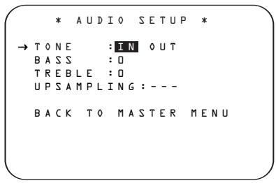
Figure 3
The first line controls whether or not the bass/treble tone controls are in the signal path. The normal default is for them to be in-line, but if you wish to remove them from the circuit for "flat" response, first make certain that the cursor is pointing to the TONE line on the menu and press the Navigation Button 15 so that OUT is highlighted in reverse video.
If you wish to leave the tone controls in the signal path, the amount off boost or cut for bass and treble may be adjusted by pressing the / Navigation Button 15 so that the cursor is next to the line for the setting you wish to adjust. Next, press the Navigation Button 15 until the desired setting is shown.
This menu also includes a setting to turn the unit's upsampling feature on or off. In normal use, this feature is turned off, which means that digital sources are processed at their native sample rate. For example, a 48kHz digital source will be processed at 48kHz. However, the AVR 430 allows you to upsample the incoming 48kHz signals to 96kHz for added resolution.
To take advantage of this feature, press the / Navigation Button 15 so that the cursor is next to the UPSAMPLING line and press the / Navigation Button 15 so that ON is highlighted in reverse video. Note that this feature is only available for the Dolby Pro Logic II-Music, Dolby Pro Logic II-Movie and Dolby Pro Logic.
When all desired changes have been made on this menu, press the / Navigation Button 15 so that the cursor is next to the BACK TO MAIN MENU line and press the Set Button 17.
Surround Setup
The next step is to set the surround mode you wish to use with the input that was previously selected in the INPUT menu. Since surround modes are a matter of personal taste, feel free to select any mode you wish – you may change it later. However, to make
it easier to establish the initial parameters for the AVR 430, it is best to select Dolby Pro Logic II (Movie or Music) or Logic 7 (Cinema or Music) for most analog inputs and Dolby Digital for inputs connected to digital sources. In the case of inputs such as a CD Player, Tape Deck or Tuner, you may wish to set the mode to Stereo ("Surround off") as they are not typically used with multichannel program material, and it is unlikely that surround-encoded material will be used. Alternatively, the Logic 7 Music mode is a good choice for stereo-only source material. See page 32 for more information on available surround modes.
For digital program material, the AVR will always examine the data stream and automatically select a Dolby Digital or DTS mode as applicable.
It is easiest to complete the surround setup using the full-OSD on-screen menus. From the MASTER MENU (Figure 1), press the / Navigation Button until the cursor is next to the SURROUND SELECT line. Press the Set Button until the SURROUND SELECT menu (Figure 4) is on the screen.
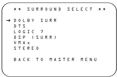
Figure 4
Each of the option lines on this menu (Figure 4) selects the surround mode category, and within each of those categories there will be a choice of the specific mode options.
The choice of modes will vary according to the speaker configuration in your system. When the SURR BACK line of the SPEAKER SETUP menu (Figure 6) is set to NONE the AVR 430 will be configured for 5.1-channel operation, and only the modes appropriate to a five-speaker system will appear. When the SURR BACK line of the SPEAKER SETUP menu (Figure 6) is set to SMALL or LARGE, the AVR 430 will be configured for 6.1/7.1-channel operation, and additional modes such as Dolby Digital EX and DTS-ES will appear, as they are only available when seven main speakers are present. In addition, some of the modes available in the AVR 430 will not appear unless a digital source is selected and is playing the correct bitstream.
To select the mode that will be used as the initial default for an input, first press the / Navigation Button 15 until the on-screen cursor is next to the desired mode's master category name, such as DOLBY SURR, DTS, DSP (SURR) or VMAX. Next, press the Set Button 17 to view the submenu. Press the / Navigation Button 15 to scroll through the available choices, and then press the Navigation Button 15 so that the cursor is next to BACK TO MASTER MENU to continue the setup process.
On the DOLBY SURROUND menu (Fig. 5), choices include Dolby Digital, Dolby Pro Logic II, Dolby Pro Logic IIx, Movie and Music, Dolby Pro Logic and Dolby Virtual Speaker Reference or Wide. For a complete description of the different Dolby Surround modes, see page 32. The Dolby Digital EX and Dolby Pro Logic IIx modes are only available when the system is set for 6.1/7.1 operation by configuring the Surround Back speakers to "Small" or "Large" as described on page 24. When a disc is playing with a Dolby Digital soundtrack that contains a special "flag" signal in the data stream, the Dolby Digital EX mode will be selected automatically. It may also be selected using this menu or through the front-panel or remote controls as shown on page 31. A complete explanation of these modes is found on page 32.
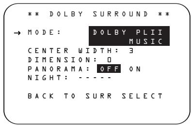
Figure 5
When the cursor is pointing to the MODE line, press the Navigation Buttons 15 to select the desired Dolby surround mode, again remembering that the choice of available modes will vary with the type of program material being played and the number of speakers in your system configuration.
When Dolby Pro Logic II Music or Dolby Pro Logic IIx Music is selected as the listening mode, three special settings are available to tailor the sound field to your listening room environment and your individual taste and preferences. (When other Dolby Surround modes are selected, dotted lines will indicate that these settings are not active.)
- Center Width: This setting adjusts the balance of the vocal information in the front soundstage between the center and front left/right speakers. The lower
settings spread the center channel sound more broadly into the left and right channels. A higher number (up to "7") produces a tighter center channel presentation.
- Dimension: This setting alters the perceived depth of the surround field by creating a shallower presentation that appears to move sounds toward the front of the room, or a deeper presentation that appears to move the center of the sound field toward the back of the room. The setting of "O" is a neutral default, with the range of adjustment shown as "R-3" for a deeper, rear-oriented sound to "F-3" for a shallower, front-oriented sound.
- Panorama: Switch this setting on or off to add an enveloping wrap-around presentation that increases the perception of sound along the sides of the room.
To change these parameters, press the / Navigation Buttons 15 while the DOLBY SURROUND menu is on the screen until the cursor is pointing to the line on the menu with the parameter you wish to change. Then, press the Navigation Buttons 15 to alter the setting to your taste.
When the DOLBY DIGITAL mode is selected, there are additional settings available for the Night mode, as shown in Figure 6.
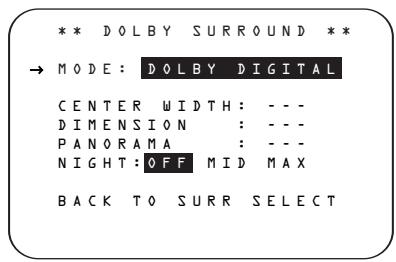
Figure 6
The Night mode is a feature of Dolby Digital that preserves the dynamic range and full intelligibility of a movie soundtrack while reducing the peak level. This prevents abruptly loud transitions from disturbing others, without reducing the sonic impact of a digital source. The Night mode is only available when specially encoded Dolby Digital signals are played.
To adjust the Night mode setting, make certain that the cursor is on the NIGHT line of the DOLBY menu. Next, press Navigation Button 15 to choose between the following settings, as they appear in the on-screen display:
OFF: When OFF is highlighted, the Night mode will not function.
MID: When MID is highlighted, a mild compression will be applied.
MAX: When MAX is highlighted, a more severe compression algorithm will be applied.
We recommend that you select the MID setting as a starting point and change to the MAX setting later, if desired.
The Night mode may also be adjusted directly any time a Dolby Digital source is playing by pressing the Night Mode Button 30. When the button is pressed, D-RANGE will appear in the lower third of the video screen and in the Lower Display Line 17. Press the / Navigation Button 15 within three seconds to select the desired setting.
When all settings for the surround setup have been made, press the / Navigation Button 15 so that the cursor is next to BACK TO MASTER MENU, and press the Set Button 17 to return to the MASTER MENU.
On the DTS menu, the selection choices made with the Navigation Button on the remote are determined by a combination of the type of program material in use and whether the 5.1- or 6.1/7.1-channel configuration is in use.
When a DTS source is playing, the choice of modes for 7.1 systems will vary according to the type of program source (DTS 5.1, DTS-ES Matrix or DTS-ES Discrete). Press the Navigation Button 15 to scroll through the choices that are available for your system and the program in use. The DTS Neo:6 Music mode is available with analog and PCM digital stereo sources and the DTS Neo:6 Cinema mode is available with analog matrix surround-encoded sources to deliver an enhanced 5.1-channel sound field.
When the 5.1 configuration is in use, the AVR will automatically select the 5.1 version of DTS processing when a DTS data stream is selected. When the 6.1/7.1 mode is selected, the DTS-ES Discrete mode will automatically be activated when a DTS source with the ES Discrete "flag" is in use. When a non-ES DTS disc is in use, you may select the DTS-ES Matrix mode through this menu to create a full eight-speaker surround mode. See page 32 for a complete explanation of the DTS modes.
On the LOGIC 7 menu, the selection choices made with the Navigation Button on the remote are determined by whether the 5.1- or 6.1/7.1-channel configuration is in use. In either case, the selection of a Logic 7 mode enables Harman Kardon's exclusive Logic 7 processing to create fully enveloping, multichannel surround from either two-channel Stereo or Matrix-encoded programming such as VHS cassettes, laser discs or television broadcasts produced with Dolby surround.
In the 5.1 configuration, you may select the Logic 7/5.1 Music, Cinema or Enhance mode. They work best with two-channel music, surround-encoded programs or standard two-channel programming of any type, respectively. For 6.1/7.1 configurations, the Music and Cinema modes may be selected. The Logic 7 modes are not available when either Dolby Digital or DTS Digital soundtracks are in use. See page 32 for a complete explanation of the Logic 7 modes.
On the DSP (SURR) menu, the selection choices made with the Navigation Button on the remote select from one of the DSP surround modes that are designed for use with two-channel stereo programs to create a variety of sound field presentations. The choices available are Hall 1, Hall 2, Theater, VMAx Near and VMAx Far. The Hall and Theater modes are designed for multichannel installations, while the two VMAx modes are optimized for use in delivering a full surround field when only the front left and front right speakers are installed. See page 32 for a complete explanation of the DSP surround modes.
On the STEREO menu, the selection choices made with the Navigation Button on the remote may either turn off all processing and bass management for a traditional two-channel stereo presentation; select a stereo output with bass management; or select a 5 CH STEREO and 7 CH STEREO mode, depending on how many speakers are available. These two modes feed a two-channel presentation to all speakers. See page 32 for a complete explanation of the stereo modes.
To listen to an analog stereo source without any bass management, so that the left and right front speakers receive a full-range signal, straight through from the input gain section to the volume control, press the Navigation Button 15 so that SURROUND OFF appears in the highlighted video. To listen to two-channel analog sources while taking advantage of the AVR 430's bass-management system, press the Navigation Button 15 so that SURROUND OFF+DSP appears in the highlighted video.
After the selections are made on the Dolby, DTS, Logic 7, DSP (Surround) or Stereo menus, press the
/ Navigation Button 15 so that the cursor moves to the BACK TO MASTER MENU line and press the Set Button 17.
Speaker Setup
This menu tells the AVR 430 which type of speakers are in use. This is important as it adjusts the settings that decide whether your system will use the "5-
channel" or "6-channel/7-channel" modes, as well as determining which speakers receive low-frequency (bass) information.
For each of these settings, use the LARGE setting if the speakers for a particular position are traditional full-range loudspeakers. Use the SMALL setting for smaller, frequency-limited satellite speakers that do not reproduce sounds below 200Hz. Note that when "small" speakers are used, a subwoofer is required to reproduce low-frequency sounds. Remember that the "large" and "small" descriptions do not refer to the actual physical size of the speakers, but to their ability to reproduce low-frequency sounds. If you are in doubt as to which category describes your speakers, consult the specifications in the speakers' owner's manual, or ask your dealer.
This menu screen also allows you to enter the settings for the AVR 430's Quadruple Crossover feature which allows a different crossover point to be used for the front left/right, center, surround and surround back speakers. In systems where full-range or tower speakers are used for the front soundstage or where different brands or models are in use at the various speaker positions, this feature allows you to customize the bass management and redirection circuits with a precision not previously possible.
It is easiest to enter the proper settings for the speaker setup through the SPEAKER SETUP menu (Figure 6). If that menu is not already on your screen from the prior adjustments, press the OSD Button 31 to bring up the MASTER MENU (Figure 1), and then press the Navigation Button until the cursor is on the SPEAKER SETUP line. Press the Set Button 17 to bring up the SPEAKER SETUP menu (Figure 7).
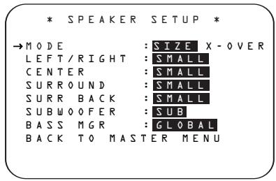
Figure 7
The first line of the SPEAKER SETUP menu (Figure 6) allows you to switch the menu to change either the underlying speaker size setting or the exact crossover point used for that speaker group. For the first pass through the menu, leave the setting at its default option of SIZE, and then proceed as outlined below. Once the speaker choices have been set, you may wish to return to this line to change the option so that the crossover settings may be adjusted.
Begin the speaker setup process by making certain that the cursor is pointing at the LEFT/RIGHT line, which sets the configuration for the front left and right speakers. If you wish to make a change to the front speakers' configuration, press the Navigation Button so that either LARGE or SMALL appears, matching the appropriate description from the definitions shown above.
When SMALL is selected, low-frequency sounds will be sent only to the subwoofer output. If you choose this option and there is no subwoofer connected, you will not hear any low-frequency sounds from the front channels.
When LARGE is selected, a full-range output will be sent to the front left and front right outputs. Depending on the choice made in the SUBWOOFER line in this menu, bass and/or LFE information may also be directed to the subwoofer.
When you have completed your selection for the front channel, press the Navigation Button 15 on the remote to move the cursor to CENTER.
Press the Navigation Button on the remote to select the option that best describes your system, based on the speaker definitions shown below.
When SMALL is selected, low-frequency center channel sounds will be sent only to the subwoofer output. If you choose this option and there is no subwoofer connected, you will not hear low-frequency sounds from the center channel.
When LARGE is selected, a full-range output will be sent to the center speaker output, and NO center channel signal will be sent to the subwoofer output.
NOTE: If you choose Logic 7 as the surround mode for the particular input source for which you are configuring your speakers, the AVR 430 will not make the LARGE option available for the center speaker. This is due to the requirements of Logic 7 processing, and does not indicate a problem with your receiver.
When NONE is selected, no signals will be sent to the center channel output. The receiver will operate in a "phantom" center channel mode and center channel information will be sent to the left and right front channel outputs. When only front left and right speakers are used, with no center or surround speakers, VMAX is a good alternative mode.
When you have completed your selection for the center channel, press the Navigation Button on the remote to move the cursor to SURROUND.
Press the Navigation Button 15 on the remote to select the option that best describes the surround speakers in your system based on the speaker definitions shown on this page.
When SMALL is selected, low-frequency surround channel sounds will be sent to the subwoofer output only. If you choose this option and there is no subwoofer connected, you will not hear any low-frequency sounds from the surround channels.
When LARGE is selected, a full-range output will be sent to the surround channel outputs, and NO surround channel signals will be sent to the subwoofer output.
When NONE is selected, surround sound information will be split between the front left and front right outputs. For optimal performance when no surround speakers are in use, the Dolby Virtual Speaker mode should be used.
When you have completed your selections for the main surround channels, press the Navigation Button on the remote to move the cursor to SURR BACK. This line serves two functions: It not only configures the setting for the surround back channels when they are present; it also tells the AVR 430's processing system to configure the unit for either 5.1 or 6.1/7.1 operation.
Press the Navigation Button on the remote to select the option that best describes the speakers in use at the left and right back surround positions based on the definitions on this page:
When NONE is selected, the system will adjust so that only 5.1-channel surround processing/decoding modes are available and the surround back amplifier channels will not be used. When this is the case for your system, you may wish to take advantage of the availability of this amplifier channel pair for use in powering a second set of speakers that have their source selected by the AVR 430's multiroom control system. See page 39 for more information.
When SMALL is selected, the system will adjust so that the full complement of 6.1/7.1 surround processing/decoding modes are available, and low-frequency information below the crossover point will be sent to the subwoofer output. If you choose this option and there is no subwoofer connected, you will not hear any low-frequency sounds from the surround back channels.
When LARGE is selected, the system will adjust so that the full complement of 6.1/7.1 surround processing/decoding modes are available, and a full-range signal will be sent to the surround back channels, with no low-frequency information sent to the subwoofer output.
When you have completed your selection for the back surround channels, press the Navigation Button on the remote to move the cursor to SUBWO OFER.
Press the Navigation Button on the remote to select the option that best describes your system.
The choices available for the subwoofer position will depend on the settings for the other speakers, particularly the front left/right positions.
If the front left/right speakers are set to SMALL, the subwoofer will automatically be set to SUB, which is the "on" position.
If the front left/right speakers are set to LARGE, three options are available:
- If no subwoofer is connected to the AVR 430, press the Navigation Button 15 on the remote so that NONE appears in the on-screen menu. When this option is selected, all bass information will be routed to the front left/right "main" speakers.
- If a subwoofer is connected to the AVR 430, you have the option to have the front left/right "main" speakers reproduce bass frequencies at all times, and have the subwoofer operate only when the AVR 430 is being used with a digital source that contains a dedicated low-frequency effects, or LFE soundtrack. This allows you to use both your main and subwoofer speakers to take advantage of the special bass sounds created for some movies. Press Navigation Button 15 on the remote so that SUB (LFE) appears in the on-screen menu.
- If a subwoofer is connected and you wish to use it for bass reproduction in conjunction with the main front left/right speakers, regardless of the type of program source or Surround mode you are listening to, press the Navigation Button 15 on the remote so that SUB L/R + LFE appears in the on-screen menu. When this option is selected, a full-range signal will be sent to the front left/right "main" speakers, and the subwoofer will receive LFE information and the bass frequencies under the selected crossover point.
When all initial speaker "size" settings have been made, you now have the option to take advantage of the AVR 430's Quadruple Crossover system, which allows individual crossover settings to be made for each speaker grouping. The low-frequency crossover point is set by the design of your speakers. Depending on the design and driver complement of your speakers, it is usually the lowest possible frequency the speaker is capable of reproducing.
Before making any changes to the settings for the crossover point, we suggest that you find the crossover point for the speakers in each of the four groupings, front left/right, center front, surround and surround back, by looking at the specifications page of each speaker's owner's manual, by getting that information from the manufacturer's Web site, or by contacting your dealer or the manufacturer's customer service department. You will need this figure to accurately configure the next group of settings.
Note that when any speaker group other than the front left/right speakers is set to LARGE, the crossover may not be adjusted, as the feed will be full-range, with no sound being derived for the subwoofer at that position.
The factory default setting for all speaker positions is 100Hz. If that setting is acceptable for all channels, then no adjustments are needed and you may skip this section. However, should you wish to change one of the settings, please proceed by pressing the
Navigation Button 15 so that the cursor moves back up to the MODE line. Press the Navigation Button 15 so that X-OVER is highlighted and the menu data will change to the screen shown in Figure 8.
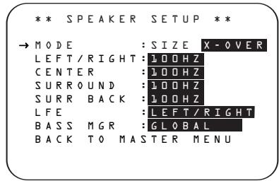
Figure 8
To change the setting for any of the four speaker groups, press the Navigation Button 15 until the cursor is next to the speaker group where you wish to make a change and then press the Navigation Button 15 until the desired setting appears. The available choices for low-frequency information to be sent to the subwoofer, rather than to the main speaker channel, are 40Hz , 60Hz , 80Hz , 100Hz , 120Hz and 200Hz . Pick the choice that is identical to the information for the speakers, or if an exact match is not possible, pick the closest choice that is ABOVE the speaker's low-frequency limit or crossover point to avoid the creation of a low-frequency "hole" where your system will have no bass information.
The setting for the crossover point for the LFE channel, which is created to provide specific low-frequency information in many movies with digital soundtracks, may be set to match the crossover for any of the four speaker
groups. Since the crossover point commonly used in the creation of the LFE channel is 120Hz we recommend that you select the speaker group whose crossover point is closest to 120Hz . To do this, press the /
Navigation Button 15 until the cursor is next to the LFE line, and then press the Navigation Button 15 until the name of the speaker group with the desired crossover frequency appears. Of course, you may also experiment with different settings to find the one that provides the smoothest and most complete bass response in your particular listening environment.
When all crossover settings have been made, or in those cases where none are needed, press the
Navigation Button 15 so that the cursor is next to the BASS MGR line to make the final setting on this menu.
This setting allows you to use the same speaker configuration and crossover settings for all inputs, or to have different settings for each input. In most cases, the factory default setting of GLOBAL will be appropriate, as most listeners do not need to have individualized speaker settings. However, some listeners, particularly those with full-range front speakers that are used for both movies and music, may prefer that different bass-management settings be used when listening to music through a CD player as opposed to a movie from a DVD player, VCR or cable/satellite set-top.
If you wish to customize the settings for speaker size individually for each input, make certain that the Mode line of the SPEAKER SETUP menu is set to SIZE and that the cursor is on the BASS MGR line and press the / Navigation Button 15 so that INDEPENDENT appears in highlighted video. When this setting is entered by exiting the menu, the configuration settings just entered will apply to the current input ONLY, and you will need to go back to the INPUT menu to select another input, and then return to this menu page again to change the settings for the next input. Repeat the procedure for any input where you wish to have a different set of speaker-configuration settings.
NOTE: When the INDEPENDENT setting is activated you may assign different speaker size settings to each input to accommodate different bass-management settings that match your preferences with the type of program material normally used with a particular source. (For example, when movies are played from DVD and music from a CD player.) However, the actual speaker crossover settings are set only once and do not change with the input selection. The reason for this is that while bass-management preferences may vary, the actual speakers remain the same regardless of the bass-management and redirection settings.
When all speaker selections have been made, press the Navigation Button 15 and then the Set Button 17 to return to the MASTER MENU.
Delay Settings
Due to the different distances between the listening position and each speaker position, the amount of time it takes for sound to reach your ears from each channel is different. You may compensate for this difference through the use of the delay settings to adjust the timing for the speaker placement and acoustic conditions in your listening room or home theater.
The AVR 430's advanced software enables you to quickly and easily set delay times without the need to calculate them using a complex formula. Instead, all you need to do is measure the approximate distance between your listening position and each of the speakers in your system. When you enter those distances into the AVR's memory as shown below, the AVR's microprocessor does the rest of the work, calculating the proper delay time. The measurements need not be accurate to the inch, as the system is designed to accommodate a typical listening area rather than require the precise measurement to one "sweet spot" position.
In addition to adjusting the delay time for each individual speaker position, the AVR 430 is among the few AV receivers that allows you to adjust the delay for the combined output of all speakers as a group. This feature is called AV Sync Delay; it allows you to compensate for delays to the video image that may be caused by the processing in products such as digital video displays, video scalers, digital cable or satellite systems, or personal video recorders. With proper adjustment of the setting for AV Sync Delay, you can eliminate the loss of lip sync that may be caused by digital video applications.
Due to the differences between the way surround modes operate, some modes allow for a greater range of delay times than others. To avoid problems, we recommend that delay times be adjusted using the Dolby Digital mode. If a different mode is selected at a later time, the AVR 430 will automatically select the closest delay settings available for the surround mode in use.
Delay times are adjustable only for the Dolby and DTS modes, so you will notice that the DELAY menu may not be accessed for other modes, such as Logic 7. In addition, when a non-Dolby Digital mode such as Dolby Pro Logic II is selected, adjustments may be made to the Surround speakers only.
To set the delay time for a specific input, the DELAY ADJUST menu (Figure 9 should be
visible on your on-screen display. If the system is not already at that point, press the OSD Button 31 to bring up the MASTER MENU, press the Navigation Button 15 three times or until the on-screen cursor is pointing at the DELAY ADJUST line. Press the Set Button 17 to call up the menu.
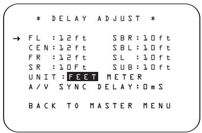
Figure 9
Once the DELAY ADJUST menu is on your screen, note that the default for distance settings is in feet. If your measurements are in feet, proceed to the next step; if your measurements are made in meters, press the Navigation Button until the on-screen cursor is at the UNIT line on the menu. Then, press the Navigation Button so that METER is highlighted. When the change in measurement units is made, press the Navigation Button to return the cursor to the FL position.
With the on-screen cursor pointing to FL, press the Navigation Button until the distance from the center speaker to the preferred listening position is entered. Next, press the Navigation Button to move the cursor to the next line and use the Navigation Button again to enter the distance from the main listening position to the center speaker. Repeat the procedure for all active speaker positions, first using the Navigation Button to change to the next position, and then use the Navigation Button to change the setting. Note that only the speaker positions that have been set to LARGE or SMALL in the SPEAKER SETUP menu, as shown on page 23, may be adjusted. The appearance of three dashes next to a speaker position in place of a distance setting indicates that you have not configured an active speaker for that location.
When the delay time for all speaker positions has been set you may return to the master menu by pressing the / Navigation Button 15 until the cursor is pointing to BACK TO MASTER MENU and then pressing the Set Button 17. However, if you have a digital video source or a digital video display that causes lack of lip sync you may use the A/V Sync adjust feature to delay the audio signal
as it is sent to all channels (as opposed to the individual settings) so that the picture and sound are brought back together. We recommend that this adjustment be made using the direct access controls on the remote, as shown below. That enables you to see the image while making the adjustment; however, you may also adjust it here using the menu system.
To adjust the A/V Sync delay, press the / Navigation Button 15 so that the cursor is pointing to the A/V Sync Delay line on the menu and then press the / Navigation Button 15 to delay the sound sufficiently so that it matches the on-screen video.
The delay settings may be adjusted at any time using the remote control and while viewing an on-screen image by pressing the Delay Select Button 37. The A/V Sync Delay setting is first, and it may be adjusted by pressing the Set Button 17 within five seconds of when the A/V SYNC DELAY message appears in the on-screen display and the Lower Display Line 14. Then, press the Navigation Button 15 to enter the desired delay setting that brings the video and sound back in sync. Press the Set Button 17 again to enter the setting.
Note that the A/V Sync delay setting is unique to each video input source, so you may enter a different setting to compensate for the differences between any product attached to the Video 1, 2, 3 or 4 inputs.
To change one of the individual speaker positions directly, press the Speaker Select Button 38, followed by the / Navigation Button 15 to select the desired position as that name appears in the on-screen display and the Lower Display Line 14. When the name of the speaker position to be adjusted appears press the Set Button within five seconds. Press the / Navigation Button 15 to enter the desired delay setting for that speaker and then press the Set Button 17 to enter the setting. The / Navigation Button 15 may be used to select another position, or you may simply wait five seconds for the system to time out and return to normal operation.
When all delay settings made using the menu system have been completed, press the / Navigation Button until the cursor is pointing to the BACK TO MASTER MENU line and press the Set Button.
Output Level Adjustment
Output level adjustment is a key part of the configuration of any surround sound product. It is particularly important for a digital receiver such as the AVR 430,
as correct outputs ensure that you hear soundtracks with the proper directionality and intensity.
IMPORTANT NOTE: Listeners are often confused about the operation of the surround channels. While some assume that sound should always be coming from each speaker, most of the time there will be little or no sound in the surround channels. This is because they are only used when a movie director or sound mixer specifically places sound there to create ambience, a special effect or to continue action from the front of the room to the rear. When the output levels are properly set, it is normal for surround speakers to operate only occasionally. Artificially increasing the volume to the rear speakers may destroy the illusion of an enveloping sound field that duplicates the way you hear sound in a movie theater or concert hall.
Before beginning the output level adjustment process, make certain that all speaker connections have been properly made. The system volume should be set to the level that you will use during a typical listening session. While the AVR 430 allows you to set output levels manually, we recommend that the EzSet system be used when the AVR is first installed to establish the initial level settings.
Using EzSet
Harman Kardon's exclusive EzSet remote makes it possible to quickly and accurately set the AVR 430's output levels without the use of a sound-pressure meter, although manual adjustment is also available. However, for the easiest setup, follow these steps while seated in the listening position that will be used most often:
- Make certain that all speaker positions have been properly configured for their "large" or "small" settings (see pages 23 - 25) and turn off the OSD system if it is in use.
- Adjust the volume so that it is at -1.5 dB, as shown in the on-screen display or Lower Display Line 14.
- Press and hold the SPL Select Button 45 on the remote until the red LED under the Set Button 17 lights and the LCD screen in the remote changes to the display shown in Figure 10.

Figure 10
- Press the Set Button within five seconds to move to the next step.
- Press the Navigation Button until the lower line of the remote's LCD display shows the number of
speakers in your system. (Don't count the subwoofer or speakers that are part of a multizone system.) For example, if you have left, center, right, surround left and right, and surround back left and right speakers for a full 7.1 system, press the button twice so that the bottom line reads 7 CHANNELS, as shown in Figure 11.

Figure 11
- Hold the remote in front of you at arm's length, being sure not to cover the EzSet Microphone Sensor 43 at the top of the remote, and press the Set Button 17 within five seconds to begin the EzSet calibration process. At this point, EzSet will take control of your AVR, starting the test tone at the front left speaker, and automatically adjusting the output level so that it is correct. During the adjustment the on-screen display and the Lower Display Line 14 will display the speaker position on the left side of the display and the offset from reference level on the right side of the display. As the levels are adjusted, the speaker position and a level indication will appear in the bottom line of the remote's LCD display (Figure 12).

Figure 12
- The channel position being adjusted will flash in the Speaker/Channel Input Indicators 12. If the test noise is heard from a channel other than the one shown in the indicator, there is an error in the speaker connections. If this is the case, press the Test Button 6 TWICE to stop the adjustment. Then turn the unit off and verify that all speakers are connected to the proper Speaker Outputs
67910 and that any connections made to speakers powered by optional amplifiers through the Preamp Outputs 3 are correct. - During the adjustment process for each channel, you will see indications of LOW, HIGH and a level readout in dB. This is normal, and it confirms that EzSet is doing its job of changing the levels to match the desired reference.
-
If a channel cannot be adjusted to the proper reference level, you will see FAIL displayed in the remote's bottom LCD line before the test tone moves to the next channel. This is usually an indication that the volume control was set too low. When EzSet stops circulating the tone through all channels and returns to normal, adjust the volume level and repeat the procedure from Step 3.
-
After the test noise has circulated once through each channel, it will send the tone to each channel once again, to verify the settings.
- After two complete circulations of the tone, the levels are set. Upon completion of the second circulation, the LCD Information Display 3 will flash COMPLETE three times and then go out. The tone will stop and the AVR 430 will return to normal operation.
If you find that the output levels chosen by EzSet are either uncomfortably low or high, you may repeat the procedure. Return to Step 2 and adjust the master volume either slightly higher or lower to accommodate your particular room layout and your tastes. You may repeat this procedure as many times as necessary to achieve a desired result. In order to prevent possible damage to your hearing or your equipment, it is important to avoid setting the master volume above 0dB.
NOTE: The subwoofer output is not adjusted when the test tone is in use. To adjust the subwoofer output, you must use an external source, following the instructions on page 35.
Manual Output Level Adjustment
Output levels may also be adjusted manually, either to set them to a specific level with an SPL meter, or to make fine tuning adjustments to the levels obtained using the EzSet remote.
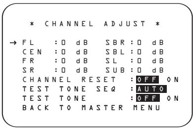
Figure 13
Manual output level adjustment is most easily done through the CHANNEL ADJUST menu (Figure 13). If you are already at the MASTER MENU, press the Navigation Button until the on-screen cursor is next to the CHANNEL ADJUST line. If you are not at the MASTER MENU, press the OSD Button to bring up the MASTER MENU (Fig. 1), and then press the Navigation Button until the on-screen cursor is next to the CHANNEL ADJUST line. Press the Set Button to bring the CHANNEL ADJUST menu (Figure 13) to the screen.
When the CHANNEL ADJUST menu first appears the test tone is off. If desired, you may immediately use the / Navigation Button 15 to select any channel for adjustment using an external source, such as a test disc, from which to judge the output levels. After the cursor is pointing to the channel to be adjusted, press the Navigation Button 15 to raise or lower the output level. However, before proceeding with any manual adjustment we recommend that you first use the AVR's internal test tone generator and automatic sequencer to send a tone to each channel so that you may verify that all speaker connections have been properly made.
To turn the test tone on and have it automatically circulate among the channels where a speaker has previously been configured (see page 24), press the / Navigation Button 15 until the cursor is pointing to the TEST TONE line on the menu. Next, press the / Navigation Button 15 until AUTO SEQ is shown in highlighted video. At this time the test tone will immediately begin to circulate clockwise around the room, playing for two seconds in each speaker before switching to the next speaker position. The cursor will blink next to the active speaker to indicate which speaker the sound should be coming from.
As the test noise circulates, listen to make certain that the sound comes from the speaker position shown in the Lower Display Line 14. If the sound from a speaker location does NOT match the position indicated in the display, turn the AVR 430 off using the Main Power Switch A and check the speaker wiring or connections to external power amplifiers to make certain that each speaker is connected to the correct output terminal.
After checking for speaker placement, let the test noise circulate again, and listen to see which channels sound louder than the others. Using the front left speaker as a reference, press the Navigation Button 15 to bring all speakers to the same volume level. When the Navigation Button 15 is pushed, the test noise circulation will pause on the channel being adjusted to give you time to make the adjustment. When you release the button, the circulation will resume after five seconds.
Continue to adjust the individual channels until the volume level sounds the same from each speaker. Adjustments should be made with the Navigation Button only, NOT the main volume controls. If you are using a sound-pressure level (SPL) meter for precise level adjustment, set the volume so that the meter reads 75dB, C-Weighting Slow.
You may also make these same adjustments with complete manual control over the channel being adjusted by pressing the / Navigation Button 15 until the cursor is pointing to the TEST TONE SEQ line on the menu and then using the / Navigation Button 15 to select MANUAL in the highlighted video. In the MANUAL mode, the test tone will also start immediately, but the tone will only be moved to another channel by pressing the / Navigation Button 15. When the manual sequencing mode is active, the tone is turned off by pressing the / Navigation Button 15 until the cursor is pointing to the TEST TONE line and the / Navigation Button 15 is then pressed to select OFF in the highlighted video.
The AVR's EzSet feature may also be used as an SPL meter to assist in accurate setting of the output levels, when either the internal test tone or an external source such as a test disc is used. To use the remote as an SPL meter, follow these steps:
- Press and hold the SPL Select Button 45 on the remote until the red LED under the Set Button 17 lights and the LCD screen in the remote changes to the display shown in Figure 10.
- Press the Navigation Button 15 once to change the bottom line of the remote's LCD display to read MANUAL SPL as shown in Figure 14.

Figure 14
- Press the Set Button within five seconds to activate the remote's manual mode, so that it functions as an SPL meter. The right corner of the bottom line of the remote's display will show the output level of the speakers as the test tone circulates. The level will show as a direct SPL indication between 66dB and 79dB. Below 66dB the remote will read LOW and above 79dB it will read HIGH.
- When you are finished with all adjustments, press the Clear Button to return the remote to normal operation.
NOTE: The subwoofer level is not adjustable when the normal test tone is in use. The subwoofer output level may be adjusted when the channel levels are being trimmed to a program source rather than the test tone, as shown on page 35.
When all channels have an equal volume level, the adjustment is complete. To exit this menu, press the Navigation Button until the on-screen
cursor is next to the BACK TO MASTER MENU line, and then press the Set Button 17 to return to the MASTER MENU.
The output levels may also be adjusted at any time using the remote control and semi-OSD system. To adjust the output levels in this fashion, press the Test Button 6. As soon as the button is pressed, the test tone will begin to circulate as indicated earlier. The correct channel from which the test noise should be heard will be shown in the lower third of the video screen and in the Lower Display Line 14. While the test noise is circulating, the proper channel position will also be indicated in the Speaker/Channel Input Indicators 12 by a blinking letter within the correct channel.
To adjust the output level, press the / Navigation Button 15 until the desired level is shown in the display or on screen. Once the buttons are released, the test noise will begin to circulate again in five seconds.
When all channels have the same output level, press the Test Button 6 again to complete the process.
NOTE: Output level adjustment is not available for the VMAx or Surround Off modes.
Additional Input Adjustments
After one input has been adjusted for Surround mode, digital input (if any), speaker type, and output levels, go back to the INPUT SETUP line on the MASTER MENU (Figure 1) and enter the settings for each input that you will use. In most cases, only the digital input and surround mode will be different from one input to the next, while the speaker type, crossover frequency, Night mode and output level settings will usually be the same and may be quickly entered by entering the same data used for the original input.
If you wish to have different speaker "size" and crossover settings for an input, remember to change the BASS MGR setting to INDEPENDENT, as shown on page 25. When all settings and adjustments have been made, press the OSD Button to return to normal operation of the AVR.
Once the settings outlined on the previous pages have been made, the AVR 430 is ready for operation. While there are some additional settings to be made, these are best done after you have had an opportunity to listen to a variety of sources and different kinds of pro
gram material. These advanced settings are described on pages 37 and 38 of this manual. In addition, any of the settings made in the initial configuration of the unit may be changed at any time. As you add new or different sources or speakers, or if you wish to change a setting to better reflect your listening taste, simply follow the instructions for changing the settings for that parameter as shown in this section.
Having completed the setup and configuration process for your AVR 430, you are about to experience the finest in music and home theater listening. Enjoy!
Basic Operation
Once you have completed the initial setup and configuration of the AVR 430, it is simple to operate and enjoy. The following instructions will help you maximize the enjoyment of your new receiver:
Turning the AVR 430 On or Off
- When using the AVR 430 for the first time, you must press the Main Power Switch A to turn the unit on. This places the unit in a Standby mode, as indicated by the amber illumination surrounding the Standby/On Switch 1. Once the unit is in Standby, you may begin a listening session by pressing the Standby/On Switch 1 on the front panel, or the Power On Button 2 or AVR Selector 5 B on the remote. This will turn the unit on and return the AVR to the input source that was last used. The unit may also be turned on from Standby by pressing any of the Input Selector Buttons 4 34 44 C D on the remote or the Input Source Selector Button 7 on the front panel.
Whenever the AVR is turned on, you will see all of the front-panel indicators light up for a few seconds. This is normal, and it is part of the unit's power-on self test procedure.
NOTE: After pressing one of the Input Selector Buttons 4344C to turn the unit on, press the AVR Selector 5B to set the remote control to the AVR 430 functions.
To turn the unit off at the end of a listening session, simply press the Standby/On Switch 1 on the front panel or the Power Off Button 1 A on the remote. Power will be shut off to any equipment plugged into the rear-panel Switched AC Accessory Outlet 1 and the illumination around the Standby/ On Switch 1 will turn amber.
When the remote is used to turn the unit "off," it is actually placing the system in a Standby mode, as indicated by the amber lighting around the Standby/On Switch 1.
- To program the AVR 430 for automatic turn-off, press the Sleep Button on the remote. Each press of the button will decrease the time before shut-down in the following sequence:
The sleep time will be displayed in the Lower Display Line 14 and it will count down until the time has elapsed.
When the programmed sleep time has elapsed, the unit will automatically turn off. The front-panel display will dim to one-half brightness when the Sleep function is programmed. To cancel the Sleep function, press
and hold the Sleep Button 29 until the information display returns to normal brightness; the Sleep indicator numbers will disappear and the words SLEEP OFF will appear in the Lower Display Line 14.
When you will be away from home for an extended period of time, it is always a good idea to completely turn the unit off with the front-panel Main Power Switch A.
NOTE: All preset memories are lost if the unit is left turned off by using the Main Power Switch A for more than four weeks.
Source Selection
- To select a source, press any of the Input Selector Buttons 4 34 44 C D on the remote.
- The input source may also be changed by pressing the front-panel Input Source Selector Button 7. Each press of the button will move the input selection through the list of available inputs.
- When a new input is selected, the AVR will automatically switch to the digital input (if selected), surround mode, component video input, A/V Sync Delay and Night Mode configurations that were in effect the last time that input was used. If the BASS MGR line on the SPEAKER SETUP menu (Fig. 7) was set to INDEPENDENT, as described on page 25, the settings for speaker size and crossover points will also change to the preset values.
- The front-panel Video 4 Inputs L , Optical Digital 3 Input U or the Coaxial Digital 3 Input K may be used to connect a device such as a video game or camcorder to your home entertainment system on a temporary basis.
- As the input source is changed, the new input name will appear momentarily as an on-screen display in the lower third of the video display. The input name will also appear in the Upper Display Line 13 and in the front-panel Input Indicators 11.
- When an audio source is selected, the last video input used remains routed to the Video 1/Video 2 Video Outputs 17 and Video Monitor Outputs 14. This permits simultaneous viewing and listening to different sources.
- When a composite or S-Video source is selected, the video signal for that input will be routed to the Video Monitor Output 14 and will be viewable on a TV monitor connected to the AVR 430.
6-Channel/8-Channel Direct Input
- There are two input choices available for use with sources such as a DVD-Audio or SACD player that are connected to the 8-Channel Direct Inputs ④ . Select the appropriate input according to the way your system and source equipment is configured:
The BCH DIRECT input should be used when the SBR and SBL inputs are NOT in use. It passes the input from the source directly through to the volume control without any analog to digital conversion and it mutes the unused input jacks to prevent unwanted noise from interfering with system performance.
The 8CH DIRECT input should be used when an input is connected to all eight 8-Channel Direct Inputs 40. It passes the input from the source directly through to the volume control without any analog to digital conversion and it mutes the unused input jacks to prevent unwanted noise from interfering with system performance.
Volume and Tone Control
- Adjust the volume to a comfortable level using the front-panel Volume Control 10 or remote Volume Up/Down Buttons 18.
- To temporarily silence all speaker outputs, press the Mute Button 33. This will interrupt the output to all speakers and the headphone jack, but it will not affect any recording or dubbing that may be in progress. When the system is muted, the word MUTE will flash in the on-screen display and Upper Display Line 13, press the Mute Buttons 33 again to return to normal operation.
- The unit's tone controls may be taken out of the signal path by pressing the Tone Mode Button on the front panel or the remote 32 . The first press of either button will show a message in the on-screen display and Lower Display Line 14 with the current status of the tone controls. The system default is TONE IN, which indicates that the bass and treble controls are active. Press the / Navigation Button 15 on the remote or the / Button 16 on the front panel to change the setting to TONE OUT, which is "flat" response without the tone controls being active.
- When the tone controls are active, the amount of bass and treble boost/cut may be adjusted by first pressing the Tone Mode Button on the front panel or the remote two or three times until the desired setting (BASS MODE or TREBLE MODE) appears in the on-screen display and the
Lower Display Line 14. Next, use the / Navigation Button 15 on the remote or the / Button on the front panel H to change the setting as desired. The unit will return to normal operation within five seconds after the setting is changed. Note that the tone control settings are applied to the front left/right speakers only.
- For private listening, simply place a standard 1 / 4" stereo headphone plug or adaptor into the Headphone Jack B behind the door 9 on the front panel. The speakers will automatically mute and a two-channel stereo signal will be sent to the headphones. The Lower Display Line 14 will read DOLBY H: BP, indicating that the headphone output is in the Bypass mode, and to confirm that no processing is being used.
- When the headphones are in use, you may take advantage of the Dolby Headphone modes to bring added spaciousness to headphone listening. Press the Dolby Mode Select Button 43 or the Surround Mode Selector 3 to cycle through the three Dolby Headphone modes to select the one that you prefer.
Surround Mode Selection
One of the most important features of the AVR 430 is its ability to reproduce a full multichannel surround sound field from digital sources, analog matrix surround-encoded programs and standard stereo programs.
Selection of a surround mode is based on personal taste, as well as the type of program source material being used. For example, motion pictures or TV programs bearing the logo of one of the major surround-encoding processes, such as Dolby Surround or DTS Stereo may be played in either the Dolby Digital, Dolby Pro Logic II Cinema, DTS Neo:6 Cinema, or Logic 7 Cinema surround modes, depending on the source material.
NOTE: Once a program has been encoded with matrix surround information, it retains the surround information as long as the program is broadcast in stereo. Thus, movies with surround sound may be decoded via any of the analog surround modes such as Pro Logic II Cinema, Logic 7 Cinema or DTS Neo:6 Cinema, when they are broadcast via conventional TV stations, cable, pay-TV and satellite transmission. In addition, a growing number of made-for-television programs, sports broadcasts, radio dramas and music CDs are also recorded in surround sound. You may view a list of these programs at the Dolby Laboratories Web site at www.dolby.com.
Even when a program is not listed as carrying intentional surround information, you may find that the Pro Logic II, Pro Logic IIx, Logic 7 Enhanced or DTS Neo:6, VMAx and the Hall or Theater modes often deliver enveloping surround presentations through the use of the natural information present in all stereo recordings.
Surround modes may be changed at any time by using either the front panel or remote control. To select a new surround mode from the front panel, first press the Surround Mode Group Selector Button 2 until the desired major surround mode group such as Dolby, DTS or Logic 7 is selected. Next, press the Surround Mode Selector Button 3 to choose the specific individual surround mode.
To select a surround mode using the remote, press the button for the major surround mode group that includes the mode you wish to choose from: Dolby 43, DTS Digital 42, DTS Neo:6 41, Logic 7 8, Stereo 40 or DSP Surround 7. The first press of the button will show the current mode from that group if it is already in use, or the first available mode if you are currently using another mode. To cycle through the available modes in that group, press the button again until the desired mode appears in the Lower Display Line 14 and the on-screen display and in the front-panel Surround Mode Indicators 15.
The Dolby Digital, Dolby Digital EX, DTS 5.1, DTS-ES Matrix and DTS-ES Discrete modes may only be selected when a digital input is in use. In addition, when a digital source is present, the AVR 430 will automatically select and switch to the correct mode, regardless of the mode that has been previously selected. For more information on selecting digital sources, see the Digital Audio Playback section below.
When the 6-Channel/8-Channel direct inputs are in use, there is no surround processing, as these inputs take the analog output signals from an optional, external DVD-Audio or SACD player, or another source device and carry them straight through to the volume control without any further digital processing.
To listen to a program in traditional two-channel stereo, using the front left and front right speakers only (plus the subwoofer, if installed and configured), press the Stereo Mode Select Button 40 until SURROUND OFF appears in the Lower Display Line 14. From the front panel, press the Surround Mode Group Selector 2 until the Stereo modes appear in the on-screen display and Lower Display Line 14. Next, press the Surround Mode Selector Button 3 until SURROUND OFF appears in the on-screen display and Lower Display Line 14.
Digital Audio Playback
Digital audio is a major advancement over older analog surround processing systems. It delivers up to six discrete channels, and each channel reproduces full frequency range (20Hz to 20kHz) and offers dramatically improved dynamic range and significant improvements to signal-to-noise ratios. In addition, digital systems have the capability to deliver an additional channel that is specifically devoted to low-frequency information. This is the .1" channel referred to when you see these systems described as "5.1," "6.1" or "7.1." The bass channel is separate from the other channels, but since it is intentionally bandwidth-limited, sound designers have given it that unique designation.
Dolby Digital
Dolby Digital is a standard part of DVD, and is available on specially encoded LD discs and satellite broadcasts and it is a part of the high-definition television (HDTV) system.
An optional, external RF demodulator is required to use the AVR 430 to listen to the Dolby Digital soundtracks available on laser discs. Connect the RF output of the LD player to the demodulator and then connect the digital output of the demodulator to the Optical or Coaxial Inputs UK 36 of the AVR 430. No demodulator is required for use with DVD players or DTS-encoded laser discs.
DTS
DTS is another digital audio system that is capable of delivering 5.1 or 6.1 discrete or matrix sound field reproduction. Although both DTS and Dolby Digital are digital, they use different methods of encoding the signals, and thus they require different decoding circuits to convert the digital signals back to analog.
DTS-encoded soundtracks are available on select DVD and LD discs, as well as on special audio-only DTS discs. You may use any LD or CD player equipped with a digital output to play DTS-encoded discs with the AVR 430. All that is required is to connect the player's output to either an Optical or Coaxial Input on the rear panel 33 35 or front panel JK.
In order to listen to DVDs encoded with DTS soundtracks, the DVD player must be compatible with the DTS signal, which is indicated by a DTS logo on the player's front panel. Early DVD players may not be able to play DTS-encoded DVDs. This does not indicate a problem with the AVR 430, as some players cannot pass the DTS signal through to the digital outputs. If you are in doubt as to the capability of your DVD player to handle DTS discs, consult the player's owner's manual.
(Continued on page 33)
Surround Mode Chart
| MODE | FEATURES |
| Dolby Digital | Available only with digital input sources encoded with Dolby Digital data. It provides up to five separate main audio channels and a special dedicated low-frequency effects channel. |
| Dolby Digital EX | Available when the receiver is configured for 6.1/7.1 channel operation, Dolby Digital EX is the latest version of Dolby Digital. When used with movies or other programs that have special encoding, Dolby Digital EX reproduces specially encoded soundtracks so that a full 6.1/7.1 soundfield is available. When the receiver is set for 6.1/7.1 operation and a Dolby Digital signal is present, the EX mode is automatically selected. Even if specific EX encoding is not available to provide the additional channel, the special algorithms will derive a 6.1/7.1 output. |
| DTS 5.1 | When the speaker configuration is set for 5.1-channel operation, the DTS 5.1 mode is available when DVD, audio-only music or laser discs encoded with DTS data are played. DTS 5.1 provides up to five separate main audio channels and a special dedicated low-frequency channel. |
| DTS-ES 6.1 Matrix DTS-ES 6.1 Discrete | When the speaker configuration is set for 6.1/7.1 operation, playback of a DTS-encoded program source will automatically trigger the selection of one of the two DTS-ES modes. Newer discs with special DTS-ES discrete encoding will be decoded to provide six discrete, full-bandwidth channels plus a separate low-frequency channel. All other DTS discs will be decoded using the DTS-ES Matrix mode, which creates a 6.1-channel sound field from the original 5.1-channel soundtrack. |
| Dolby Pro Logic II Movie Music Pro Logic | Dolby Pro Logic II decodes full-range, discrete, left, center right, right surround and left surround channels from either matrix surround-encoded programs or conventional stereo sources when an analog input is in use. The Dolby Pro Logic II Movie mode is optimized for movie soundtracks, while the Pro Logic II Music mode should be used with musical selections. The Pro Logic mode re-creates original Pro Logic processing for those who prefer that presentation. |
| Dolby Pro Logic IIx Music Movie | Dolby Pro Logic IIx is the latest extension of Dolby Pro Logic II technology that creates a discrete 6.1 and 7.1 sound field from matrix surround or two-channel stereo sources in systems configured for surround back speakers. Both Movie and Music versions of Pro Logic IIx are available. These modes may also be applied to a six-channel source connected to the 8-Channel Direct Inputs 40 so that the sound field is enhanced by adding back surround channels, as well as to enable the MAIN DOWNMIX option in the multiroom system so that a six channel direct input may be used as a source for the remote room. |
| Logic 7 Cinema Logic 7 Music Logic 7 Enhance | Exclusive to Harman Kardon for receivers, Logic 7 is an advanced mode that extracts the maximum surround information from either surround-encoded programs or conventional stereo material. When your system has been configured for use with Surround Back Speakers (see page 25), you may choose between either 7.1 or 5.1 versions of the Logic 7 modes, while only the 5.1 versions are available when there are no Surround Back Speakers. The Logic 7 C (or Cinema) mode should be used with any source that contains Dolby Surround or similar matrix encoding. Logic 7 C delivers increased center channel intelligibility, and more accurate placement of sounds with fades and pans that are much smoother and more realistic than with other decoding techniques. The Logic 7 M or Music mode should be used with analog or PCM stereo sources. Logic 7 M enhances the listening experience by presenting a wider front soundstage and greater rear ambiance. Both Logic 7 modes also direct low-frequency information to the subwoofer (if installed and configured) to deliver maximum bass impact. The Logic 7 E (or Enhance) mode, available only when the 5.1 option is chosen, is an extension of the Logic 7 modes that is primarily used with musical programs. Logic 7 adds additional bass enhancement that circulates low frequencies in the 40Hz to 120Hz range to the front and surround speakers to deliver a less localized soundstage that appears broader and wider than when the subwoofer is the sole source of bass energy. |
| DTS Neo:6 Cinema DTS Neo:6 Music | These two modes are available with analog sources playing to create a three-channel, five-channel or six-channel surround presentation from matrix-encoded or stereo sources. Select the Cinema version of Neo:6 when a program with matrix surround encoding is present. Select the Music version of Neo:6 for optimal processing when a nonencoded, two-channel stereo program is being played. |
| Theater | The Theater mode creates a sound field that resembles the acoustic feeling of a standard live performance theater. |
| Hall 1, Hall 2 | The two Hall modes create sound fields that resemble a small- (Hall 1) or medium-sized (Hall 2) concert hall. |
| VMAx Near VMAx Far | When only the two front-channel loudspeakers are used, VMAx delivers a three-dimensional sound space with the illusion of "phantom speakers" at the center and surround positions. The VMAx N, or "Near Field" mode should be selected when your listening position is less than five feet from the speakers. The VMAx F, or "Far Field," mode should be selected when your listening position is greater than five feet from the speakers. |
| Dolby Virtual Speaker Reference Wide | Dolby Virtual Speaker uses advanced technology to simulate the sonic signature of a speaker location even when there is no speaker physically present in that location. The Reference ("REF") mode activates the front left/right or front left/center/right speakers to simulate a 5.1 presentation with accurate localization. The Wide mode virtualizes additional front-channel speakers to create a wider image and a more enveloping sound field. It is available no matter how many speakers are present. |
| 5-Channel Stereo 7-Channel Stereo | These modes take advantage of multiple speakers to place a stereo signal at both the front and back of a room. They places the same signal at the front-left and surround-left, and front-right and surround-right speakers. The center channel is fed a summed mono mix of the in-phase material of the left and right channels. |
| Surround Off (Stereo) | This mode turns off all surround processing and presents the pure left- and right-channel presentation of two-channel stereo programs. |
| Dolby Headphone DH1 DH2 DH3 | Dolby Headphone enables ordinary stereo headphones to portray the sound of a five-speaker surround-playback system. The DH1 mode creates headphones presentation that resembles a small, well-damped room and is appropriate for use with both movies and music-only recordings. The DH2 mode creates a more acoustically live room particularly suited to music listening. The DH3 mode creates a larger room, more like a concert hall or movie theater. |
NOTE: Some DVD players have a default setting that does not pass through the DTS signal. Before playing DVDs with a DTS soundtrack, make certain that the settings in your DVD player have been properly adjusted so that DTS audio is passed through. Consult the owner's manual for your DVD player for more information on making these settings.
Selecting a Digital Source
To utilize either digital mode, you must have properly connected a digital source to the AVR 430. Connect the digital outputs from DVD players, HDTV receivers, satellite systems or CD players to the Optical or
Coaxial Inputs JK 33 36. In order to provide a backup signal and a source for analog stereo recording, the analog outputs provided on digital source equipment should also be connected to their appropriate inputs on the AVR 430 rear panel (e.g., connect the analog stereo audio output from a DVD to the DVD Audio Inputs 32 on the rear panel when you connect the source's digital outputs).
If you have not already configured an input for a digital source using the on-screen menus as shown on page 21, first select the input using the remote or front panel controls, as outlined in this manual. Next, select the digital source by pressing the Digital
Select Button 16F and then using the /
Navigation Button 15 on the remote or the
Button H on the front panel to choose any of the OPTICAL or COAXIAL inputs, as they
appear in the Upper Display Line 13 or on-screen display. When the digital source is playing, the
AVR 430 will automatically detect which type of digital data stream is being decoded and display that infor
mation in the Upper Display Line 13.
When both a digital and an analog connection are made between a source device and the AVR, the digital input is the default. If the digital stream is not present or is interrupted, the unit will automatically switch over to the analog inputs for the selected source.
Digital Bitstream and Surround Mode Indications
When a digital source is playing, the AVR 430 senses the type of bitstream data that is present. Using this information, the correct surround mode will automatically be selected. For example, DTS bitstreams will cause the unit to switch to DTS decoding, and Dolby Digital bitstreams will enable Dolby Digital decoding. When the unit senses PCM data from CDs or LDs, you may select any of the standard surround modes, such as Dolby Pro Logic II or Logic 7. Since the range of available surround modes is dependent on the type of digital data that is present, the AVR 430 shows you what type of signal is present. This will help you to understand the choice of modes.
When a digital source is first detected, the AVR 430 will display a message to indicate the type of bitstream
being received. This message will appear shortly after an input or surround mode is changed, and will remain in the Lower Display Line 14 for about five seconds before that portion of the display returns to the normal surround mode indication.
For Dolby Digital and DTS sources, a three-digit indication will appear, showing the number of channels present in the data. An example of this type of display is 3/2/.1.
The first number in the display message indicates how many discrete front-channel signals are present.
- A "3" tells you that separate front left, center and front right signals are available. This will be displayed for Dolby Digital 5.1 and DTS 5.1 programs.
- A "2" tells you that separate front left and right signals are available, but there is no discrete center channel signal. This will be displayed for Dolby Digital bitstreams that have stereo program material.
- A "1" tells you that there is only a mono channel available in the Dolby Digital bitstream.
The middle number in the display message indicates how many discrete surround channel signals are present.
- A "3" tells you that separate, discrete left surround, center surround and right surround signals are present. This is available only on discs with DTS-ES digital audio.
- A "2" tells you that separate surround left and right signals are available. This will be displayed for Dolby Digital 5.1 and DTS 5.1 programs.
- A "1" tells you that there is only a single, surround-encoded surround channel. This will appear for Dolby Digital bitstreams that have matrix encoding.
- A "0" indicates that there is no surround channel information. This will be displayed for two-channel stereo programs.
The last number indicates whether there is a discrete low-frequency effects (LFE) channel. This is the ".1" in the common abbreviation of "5.1" sound and it is a special channel that contains only bass frequencies.
- A "1" tells you that an LFE channel is present. This will be displayed for Dolby Digital 5.1 and DTS 5.1 programs, as available.
- A "0" indicates that there is no LFE channel information available. However, even when there is no dedicated LFE channel, low-frequency sound will be present at the subwoofer output when the speaker configuration is set to show the presence of a subwoofer.
- The information in the right side of the display will tell you if the digital audio data contains a special flag signal that will automatically activate the appro
priate 6.1 or 7.1 mode. This will be shown as EX-ON or EX-OFF for Dolby Digital bitstreams and ES-ON or ES-OFF for DTS bitstreams.
When Dolby Digital 3/2/.1 or DTS or DTS-ES signals are being played, the AVR will automatically switch to the proper surround mode, and no other processing may be selected. When a Dolby Digital signal with a 3/1/0 or 2/0/0 signal is detected, you may select any of the Dolby surround modes.
It is always a good idea to check the readout for the channel data to make certain that it matches the audio logo information shown on the back of a DVD package. In some cases, you will see an indication for "2/0/0" even when the disc contains a full 5.1, or 3/2/.1, signal. When this happens, check the audio output settings for your DVD player or the audio menu selections for the specific disc being played to make certain that the player is sending the correct signal to the AVR.
PCMPlayback
PCM is the abbreviation for Pulse Code Modulation, which is the type of digital signal used for standard CD playback, and other non-Dolby Digital and non-DTS digital sources such as Mini-Disc. When a PCM signal is detected, the Lower Display Line 14 will briefly show a message with the letters PCM, in addition to a readout of the sampling frequency of the digital signal.
In most cases, this will be PCM 44.1kHz or PCM 48kHz, though in the case of specially mastered, high-resolution audio discs, you will see a PCM 96kHz indication. Note that the sampling rate displayed is that of the incoming digital signal, and not the upsampled rate that may be applied to PCM sources when Dolby Pro Logic or Pro Logic II processing is applied, as shown on page 21.
During PCM playback you may select any surround mode except one of the Dolby Digital or DTS/DTS-ES modes.
Speaker/Channel Indicators
In addition to the bitstream indicators, the AVR 430 features a set of unique channel-input indicators that tell you how many channels of digital information are being received and/or whether the digital signal is interrupted (see Figure 15).
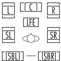
Figure 15
These indicators are the L/C/R/LFE/SL/SR/SBL/SBR letters that are inside the center boxes of the Speaker/Channel Input Indicators 12 on the front-panel. When a standard analog signal is in use, only the "L" and "R" indicators will light, as analog signals have only left and right channels.
Digital signals, however, may have two, five, six or seven channels; this depends on the program material, its method of transmission and the way in which it was encoded. When a digital signal is playing, the letters in these indicators will light in response to the specific signal being received. It is important to note that although Dolby Digital, for example, is referred to as a "5.1" system, not all Dolby Digital DVDs or programs are encoded for 5.1. Thus, it is sometimes normal for a DVD with a Dolby Digital soundtrack to trigger only the "L" and "R" indicators.
NOTE: Many DVD discs are recorded with both "5.1" and "2.0" versions of the same soundtrack. When playing a DVD, always be certain to check the type of material on the disc. Most discs show this information in the form of a listing or icon on the back of the disc jacket. When a disc does offer multiple soundtrack choices, you may have to make some adjustments to your DVD player (usually with the "Audio Select" button or in a menu screen on the disc) to send a full 5.1 feed to the AVR 430. It is also possible for the type of signal feed to change during the course of a DVD's playback. In some cases, the previews of special material will only be recorded in 2.0 audio, while the main feature is available in 5.1 audio. The AVR 430 will automatically sense changes to the bitstream and channel count and reflect them in these indicators.
The letters used by the Speaker/Channel Input Indicators 12 also flash to indicate when a bitstream has been interrupted. This will happen when a digital input source is selected before the playback starts, or when a digital source such as a DVD is paused. The flashing indicators remind you that the playback has stopped due to the absence of a digital signal and not through any fault of the AVR 430. This is normal, and the digital playback will resume once the playback is started again.
Night Mode
A special feature of Dolby Digital is the Night mode, which enables specially encoded Dolby Digital input sources to be played back with full digital intelligibility while reducing the minimum peak level by 1/4 to 1/3. This prevents abruptly loud transitions from disturbing others, without reducing the impact of the digital source. The Night mode is available only when Dolby Digital signals with special data are being played.
The Night mode may be engaged when a Dolby Digital DVD is playing by pressing the Night Mode Button 30 on the remote. Next, press the / Navigation Button 15 to select either the middle range or full compression versions of the Night mode. To turn the Night mode off, press the / Navigation Button 15 until the message in the lower third of the video display and in the Lower Display Line 14 reads D-RANGE OFF.
The Night mode may also be selected to always be on at either level of compression using the options in the DOLBY SURR menu. (See page 23 for information on using the menus to set this option.)
MP3 Audio Playback
The AVR 430 is one of the few receivers equipped for onboard decoding for the MP3 audio format used by computers and portable audio devices. By offering MP3 decoding, the AVR 430 is able to deliver precise conversion of the digital signals to an analog output, along with the benefits of listening to the MP3 audio through the AVR 430's high-current amplifier and the speakers from your surround system, rather than the smaller speakers and low-powered amplifiers typically used with computers.
To take advantage of the AVR 430's MP3 capabilities, simply connect the S/P-DIF output of a computer's sound card or the S/P-DIF output of a portable digital audio device to either the rear panel Digital Inputs 33 or the front-panel Digital Inputs JK. When the digital signal is available, the Lower Display Line 14 will indicate that an MP3 bitstream is present, and the audio will begin playing.
NOTES:
-
The AVR 430 is only capable of playing signals in the MP3 (MPEG 1/Layer 3) format. It is not compatible with other computer audio CODECs.
-
The digital audio input signal may be either optical or coaxial, but the signal must be in the S/P-DIF format. Direct connection of USB or serial data outputs is not possible, even though the signals are in the MP3 format. If you have any questions about the data output format from your computer or a sound card, check with the device's owner's manual or the manufacturer's technical support.
-
If your computer or sound card's digital output is not capable of direct connection to the AVR 430, you may use an optional, external transcoder to convert the USB output of a computer to a format compatible with the AVR.
-
Due to the wide variation in MP3 formats and encoding speeds, it is possible that the AVR 430 may not be compatible with all MP3 input signals. Some may produce unacceptable results and some may not be decoded. This is not a fault of either the computer or the AVR 430, but rather a by-product of the unpredictable nature of MP3 playback.
IMPORTANT NOTES ON DIGITAL PLAYBACK:
- When the digital playback source is stopped, or in a pause, fast forward or chapter search mode, the digital audio data will momentarily stop, and the channel position letters inside the Speaker/Channel Input Indicators 2 will flash. This is normal and does not indicate a problem with either the AVR 430 or the source machine. The AVR 430 will return to digital playback as soon as the data is available and when the machine is in a standard play mode.
- Although the AVR 430 will decode virtually all current DVD movies, CDs and HDTV sources, it is possible that some future digital sources may not be compatible with the AVR 430.
- Not all digitally encoded programs contain full 5.1- or 6.1-channel audio. Consult the program guide that accompanies the DVD or laser disc to determine which type of audio has been recorded on the disc. The AVR 430 will automatically sense the type of digital surround encoding used and adjust to accommodate it.
- When a digital source is playing, you may not be able to select some of the analog surround modes such as Dolby Pro Logic II, Hall, Theater or Logic 7.
- When a Dolby Digital or DTS source is playing, it is not possible to make an analog recording using the Tape Outputs 35 and Video 1 or Video 2 Audio Outputs 38 41. However, the digital signals will be passed through to the Digital Audio Outputs 2830K.
Tuner Operation
The AVR 430's tuner is capable of tuning AM, FM and FM Stereo broadcast stations. Stations may be tuned manually, or they may be stored as favorite station presets and recalled from a 30-position memory.
Station Selection
- Press the AM/FM Tuner Selector Button 43 on the remote to select the tuner as an input. The tuner may be selected from the front panel by either pressing the Input Source Selector 7 until the tuner is active or by pressing the Tuner Band Selector 5.
- Press the AM/FM Tuner Select Button 48 or Tuner Band Selector 5 again to switch between AM and FM so that the desired frequency band is selected.
- Press the Tuning Mode Selector 8 to select manual or automatic tuning.
When the button is pressed so that AUTO/STEREO appears in the Upper Display Line 18, each press of the Tuning Selectors 423 will put the tuner in a scan mode that seeks the next higher or lower frequency station with acceptable signal strength. An AUTO ST TUNED indication will momentarily appear when the station stops at a stereo FM station, and an AUTO TUNED indication will momentarily appear when an AM or monaural FM station is tuned. Press the Tuning buttons again to scan to the next receivable station.
When the button is pressed so that MANUAL / MONO appears in the Upper Display Line 13, each tap of the Selector will increase or decrease the frequency by one increment. When the tuner receives a strong enough signal for adequate reception, MANUAL TUNED will appear in the Lower Display Line 14.
- Stations may also be tuned directly in either the automatic or manual mode. To enter a station's frequency directly, first select the AM or FM band as desired be pressing the AM/FM Tuner Select Button 5 48 . Next, press the Direct Button 9 . Within five seconds of when DIRECT IN scrolls in the Upper Display Line 13 , enter the station frequency by pressing the Numeric Keys 11 . If you press an incorrect button while entering a direct frequency, press the Clear Button 10 to start over.
NOTE: When the FM reception of a station is weak, audio quality will be increased by switching to Mono mode by pressing the Tuning Mode Button 312 so that MANUAL/MONO appears momentarily in the Upper Display Line 13 and then goes out. This will also activate manual tuning mode.
Preset Tuning
Using the remote, up to 30 stations may be stored in the AVR 430's memory for easy recall using the frontpanel controls or the remote.
To enter a station into the memory, first tune the station using the steps outlined above. Then:
- Press the Memory Button 45 on the remote; the station's frequency will flash.
- Within five seconds, press the Numeric Keys corresponding to the location where you wish to store this station's frequency. Once entered, the preset number will appear in the Upper Display Line 13.
- Repeat the process after tuning any additional stations to be preset.
Recalling Preset Stations
- To manually select a station previously entered in the preset memory, press the Numeric Keys 11 that correspond to the desired station's memory location.
- To manually tune through the list of stored preset stations one by one, press the Preset Stations Selector Buttons 622 on the front panel or remote.
Recording
In normal operation, the audio or video source selected for listening through the AVR 430 is sent to the record outputs. This means that any program you are watching or listening to may be recorded simply by placing machines connected to the outputs for Tape Outputs ③ or Video 1/Video 2 Audio and Video Outputs 7 1 9 3 8 4 1 in the record mode.
When a digital audio recorder is connected to the Digital Audio Outputs 28-30, you are able to record the digital signal using a CD-R, MiniDisc or other digital recording system.
NOTES:
- The digital outputs are active only when a digital signal is present, and they do not convert an analog input to a digital signal, or change the format of the digital signal. In addition, the digital recorder must be compatible with the output signal. For example, the PCM digital input from a CD player may be recorded on a CD-R or MiniDisc, but Dolby Digital or DTS signals may not.
- Please make certain that you are aware of any copyright restrictions on any material you copy. Unauthorized duplication of copyrighted materials is prohibited by federal law.
Output Level Trim Adjustment
Normal output level adjustment for the AVR 430 is established using the test tone, as outlined on pages
26 - 29. In some cases, however, it may be desirable to adjust the output levels using program material such as a test disc, or a selection you are familiar with. Additionally, the output level for the subwoofer can only be adjusted using this procedure.
To adjust the output levels using program material, first set the reference volume for the front left and front right channels using the Volume Control 1018 1.
If you are using a disc with test signals or an external signal generator as the source used when the output levels are being trimmed, you may use the remote as an SPL meter to guide you to the correct level settings. To use the EzSet remote as an SPL meter, follow the instructions on page 27.
Once the reference level has been set, press the Channel Select Button 14 and FRONT L LEVEL will appear in the Lower Display Line 14. To change the level, first press the Set Button 17, and then use the / Navigation Button 15 to raise or lower the level. DO NOT use the volume control, as this will alter the reference setting.
Once the change has been made, press the Set Button 17 and then press the / Navigation Button 15 to select the next output-channel location that you wish to adjust. To adjust the subwoofer level, press the / Navigation Button 15 until WOOFER LEVEL appears in the Lower Display Line 14 or on-screen display.
Repeat the procedure as needed until all channels requiring adjustment have been set. When all adjustments have been made and no further adjustments are made for five seconds, the AVR 430 will return to normal operation.
The channel output for any input may also be adjusted using the full-OSD on-screen menu system. First, set the volume to a comfortable listening level using the Volume Control 10 18 1 . Then, press the OSD Button 31 to bring up the MASTER MENU (Figure 1). Press the Navigation Button 15 until the on-screen cursor is next to the CHANNEL ADJUST line. Press the Set Button 17 to activate the CHANNEL ADJUST menu.
Once the menu appears on your video screen, first use the / Navigation Button 15 to move the on-screen cursor so that it is next to the TEST TONE line. Press the / Navigation Button 15 so that OFF is highlighted. This will turn off the test tone and allow you to use your external test disc or other source material as the reference. Then, use the / Navigation Button 15 to select the channels to be adjusted. At each channel position, use the
Navigation Button 15 to change the output level. Remember, the goal is to have the output level at each channel be equal when heard at the listening position.
If you wish to reset all the levels to their original factory default of OdB offset, press the / Navigation Button 15 so that the on-screen cursor is next to the CHANNEL RESET line and press the / Navigation Button 15 so that the word ON is highlighted. After the levels are reset, resume the procedure outlined above to reset the levels to the desired settings. When all adjustments are done, press the / Navigation Button 15 to move the on-screen cursor so that it is next to BACK TO MASTER MENU and then press the Set Button 17 if you wish to go back to the main menu to make other adjustments. If you have no other adjustments to make, press the OSD Button 31 to exit the menu system.
NOTE: The output levels may be separately trimmed for each digital and analog surround mode. If you wish to have different trim levels for a specific mode, select that mode and then follow the instructions in the steps shown earlier.
Dim Function
Since the AVR 430 will often be used when movies or other video programming is viewed under low-light conditions, you may wish to lower the brightness of the front-panel displays and indicators so that they do not distract from the video presentation. You may dim the displays using the menu system, as shown on page 37, or you may control the brightness directly from the remote.
Simply press the Dim Button 13 once to dim the front panel to half the normal brightness level; press it again to turn the displays off. Note that when the displays are dimmed or turned off, the blue lighting around the Standby/On Switch 1 will continue to stay lit as a reminder that the AVR is still turned on. The accent lighting for the Volume Control 10 will go dark when the panel displays are at half brightness.
Note that all changes to the front-panel brightness level are temporary; the displays will return to full brightness after the AVR is turned off and then on again. To return the displays to full brightness without turning the unit off, press the Dim Button 13 as needed until the displays are on.
In addition to lowering the brightness of the displays or turning them off completely, you may wish to have them appear whenever a button on the remote or front panel is pushed, and then gradually fade out after a set time period. You may do this by making the appropriate settings in the VFD FADE TIME
OUT line of the ADVANCED SELECT
MENU, as shown on page 37.
Memory Backup
This product is equipped with a memory backup system that preserves the system configuration information and tunes preset if the unit is accidentally unplugged or subjected to a power outage. This memory will last for at least four weeks, after which time all information must be reentered.
The AVR 430 is equipped with a number of advanced features that add extra flexibility to the unit's operation. While it is not necessary to use these features to operate the unit, they provide additional options that you may wish to use.
Front-Panel-Display Fade
In normal operation, the front-panel displays and indicators remain on at full brightness, although you may also dim them or turn them off as shown on page 35. As an additional option, you may also set the AVR so that the displays are on whenever a button is pressed on the front panel or remote, but then fade out after a set period of time.
To set the front-panel displays to the Fade mode, press the OSD Button 31 to bring the MASTER MENU (Figure 1) to the screen. Press the / Navigation Button 15 so that the cursor is pointed to the ADVANCED line, and press the Set Button 17 to enter the ADVANCED SELECT menu (Figure 16).
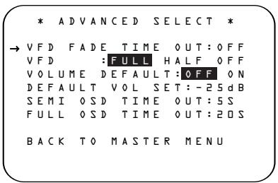
Figure 16
With the ADVANCED SELECT menu on your video display, press the / Navigation Button 15 so that the cursor is pointed to the VFD FADE TIME OUT line. Next, press the / Navigation Button 15 so that the amount of time that you wish the displays to fade out after a button is pressed is shown.
Once this time is set and the unit returned to normal operation, the displays will remain on for the time period selected whenever a button is pressed on the front panel or remote. After that time they will gradually fade out, with the exception of the lighting surrounding the Standby/On Switch 1, which remains on to remind you that the AVR is turned on. Note that if the displays have been turned completely off using the Dim Button, as shown on page 36, the Fade function will not operate.
If you wish to make adjustments to other items on the ADVANCED SELECT menu, press the / Navigation Button 15 to place the cursor next to the desired item, or place the cursor next to the BACK TO MASTER MENU line and press the Set Button 17 to make an adjustment to another menu. If you have completed all
adjustments, press the OSD Button 31 to exit the menu system.
Display Brightness
The AVR 430's front-panel displays and indicators are set at a default brightness level that is sufficient for viewing in a normally lit room. However, you may wish to occasionally lower the brightness of the display, or turn it off completely.
To change the display brightness setting for a specific listening session, you will need to make an adjustment in the ADVANCED SELECT menu. To start the adjustment, press the OSD Button 31 to bring the MASTER MENU to the screen. Press the Navigation Button 15, until the on-screen cursor is next to the ADVANCED line. Press the Set Button 17 to enter the ADVANCED SELECT menu (Figure 16).
To change the brightness setting, at the ADVANCED SELECT menu, make certain that the on-screen cursor is next to the VFD line, and press the Navigation Button until the desired brightness level is highlighted in the video display. When FULL is highlighted, the display is at its normal brightness. When HALF is highlighted, the display is at half the normal brightness level and the volume control's accent lighting will go dark. When OFF is highlighted, all of the front-panel indicators will go dark. However, the blue lighting surrounding the Standby/On Switch will remain lit to remind you that the AVR is still turned on.
Once the desired brightness level is selected, it will remain in effect until it is changed again or until the unit is turned off.
If you wish to make other adjustments, press the / Navigation Button 15 until the on-screen cursor is next to the desired setting or the BACK TO MASTER MENU line and press the Set Button 17. If you have no other adjustments to make, press the OSD Button 31 to exit the menu system.
Turn-On Volume Level
As is the case with most audio/video receivers, when the AVR 430 is turned on, it will always return to the volume setting in effect when the unit was turned off. However, you may prefer to always have the AVR 430 turn on at a specific setting, regardless of what was last in use when the unit was turned off. To change the default condition so that the same volume level is always used at turn-on, you will need to make an adjustment in the ADVANCED SELECT menu. To start the adjustment, press the OSD Button 31 to bring the MASTER MENU (Figure 1) to the screen. Press the Navigation Button 15
until the on-screen cursor is next to the ADVANCED line. Press the Set Button 17 to enter the ADVANCED SELECT menu (Fig. 16). At the ADVANCED SELECT menu, make certain that the on-screen cursor is next to the VOLUME DEFAULT line by pressing the / Navigation Button 15 as needed. Next, press the Navigation Button 15 so that the word ON is highlighted in the video display. Next, press the Navigation Button 15 once so that the onscreen cursor is next to the DEFAULT VOL SET line. To set the desired turn-on volume, press the / Navigation Button 15 until the desired volume level is shown on the DEFAULT VOL SET line. This setting may NOT be made with the regular volume controls.
NOTE: Since the setting for the turn-on volume cannot be heard while the setting is being made, you may wish to determine the setting before making the adjustment. To do this, listen to any source and adjust the volume to the desired level using the regular Volume Controls 10 18 1 . When the desired volume level to be used at turn-on is reached, make a note of the setting as it appears in the lower third of the video screen or in the Lower Display Line 14. (A typical volume level will appear as a negative number such as -25dB.) When making the adjustment, use the / Navigation Button 15 to enter this setting.
Unlike some of the other adjustments in this menu, the turn-on volume default will remain in effect until it is changed or turned off in this menu, even when the unit is turned off.
If you wish to make other adjustments, press the / Navigation Button 15 until the on-screen cursor is next to the desired setting or the BACK TO MASTER MENU line, and press the Set Button 17. If you have no other adjustments to make, press the OSD Button 31 to exit the menu system.
Semi-OSD Settings
The semi-OSD system places one-line messages at the lower third of the video display screen whenever the Volume, Input Source, Surround mode, tuner frequency or any of the configuration settings is changed. The semi-OSD system is helpful in that it enables you to have feedback on any control changes or remote commands using the video display when it is difficult to view the front-panel displays. However, you may also prefer to turn these displays off permanently. You may also want to adjust the length of time the displays remain on the screen. Both of those options are possible with the AVR 430.
To adjust the on-screen appearance of the semi-OSD system, press the OSD Button 31 to bring the MASTER MENU to the screen. Press the Navigation Button 15, until the on-screen cursor is next to the ADVANCED line. Press the Set Button 17 to enter the ADVANCED SELECT menu.
When the ADVANCED SELECT menu appears, press the / Navigation Button 15 so that the on-screen cursor is pointing to the SEMI OSD/TIME OUT line. Select one of these options:
- To keep the semi-OSD system activated, but to adjust the length of time the displays remain on the screen, press the / Navigation Button until the desired time-out is shown. The default setting is 5 seconds.
- To turn the semi-OSD system off so that it does not appear at any time, press the Navigation Button 15 so that OFF is shown on the right side of the line.
If you wish to make other adjustments, press the / Navigation Button 15 until the on-screen → cursor is next to the desired setting or the BACK TO MASTER MENU line and press the Set Button 17. If you have no other adjustments to make, press the OSD Button 31 to exit the menu system.
Full-OSD Time-Out Adjustment
The FULL OSD menu system is used to simplify the setup and adjustment of the AVR 430 by using a series of on-screen menus. The factory default setting for these menus leaves them on the screen for 20 seconds after a period of inactivity before they disappear from the screen (Time-Out). Time-Out is a safety measure to prevent image retention of the menu text in your monitor or projector, which might happen if it were left on indefinitely. However, some viewers may prefer a slightly longer or shorter period before the on-screen display disappears.
To change the full-OSD Time-Out, you will need to make an adjustment in the ADVANCED SELECT menu (Figure 16). To start the adjustment, press the OSD Button 31 to bring the MASTER MENU to the screen. Press the Navigation Button 15, until the on-screen cursor is next to the ADVANCED line. Press the Set Button 17 to enter the ADVANCED SELECT menu (Figure 16).
At the ADVANCED SELECT menu (Fig. 16) make certain that the on-screen cursor is next to the FULL OSD TIME OUT line by pressing the / Navigation Button 15 as needed. Next, press the / Navigation Button 15 until the desired time is displayed in seconds. Unlike most of the other options in this menu, this is a permanent setting change, and the Time-Out entry will remain in effect until it is changed, even if the unit is turned off.
If you wish to make other adjustments, press the / Navigation Button 15 until the on-screen cursor is next to the desired setting or the BACK TO MASTER MENU line and press the Set Button 17. If you have no other adjustments to make, press the OSD Button 31 to exit the menu system.
The AVR 430 is fully equipped to operate as the control center for a complete multiroom system that is capable of sending one source to a second zone in the house while a separate source is listened to in the main room. In addition to providing for control over the selection of the remote source and its volume, the AVR 430 offers a comprehensive range of options for powering the speakers in the second zone.
Using the line-level Multiroom Audio Outputs 29, the selected source may be fed to optional, external power amplifiers that may be matched to the specifics of the installation.
■ When the main room system is configured for 5.1 operation, the Surround Back Left/Right amplifier channels may be used to power the remote zone so that no additional amplifiers are required.
Using built-in A-BUS Ready technology, optional A-BUS modules may be connected to the AVR 430 via a single Category 5/5e wire, so that remote zone speakers may be powered directly from the A-BUS module without the need for additional power, IR sensor or volume control wires to be run to the second zone.
In addition, the AVR 430 includes a remote IR sensor input so that remote control commands from the Zone II remote included with the unit may be transmitted to the unit, while standard IR input/output jacks allow the remote zone's commands to be sent to compatible IR-controlled source devices.
Installation
Although simple remote room systems may be installed by the average do-it-yourself hobbyist, the complexity of your multizone/multiroom system involves running wires inside of walls where the services of a specially trained installer may be required. Regardless of who does the work, please remember that local building codes may govern in-wall electrical work, including proper specification of any wiring used and the way in which it is connected. You are responsible for making certain that all multiroom installation work is done properly and in compliance with all applicable codes and regulations.
For standard installations, follow the instructions shown on page 16 for the connection of speaker wire and IR remote wiring to the AVR 430.
For installations where the Surround Back Left/Right amplifier channels are used to power the remote zone, make certain that the system is configured for that type of operation, as shown on page 39.
For installations where A-BUS modules are used, follow the instructions provided with the A-BUS remote modules or keypads. Additional information will also be made available through the Harman Kardon Web site at www.harmankardon.com.
RS-232 Control
The AVR 430 is rare among AV receivers in that it provides the capability for full remote control from compatible computers or specialized remote control systems. RS-232 programming requires specialized programming knowledge and for that reason we recommend that it only be done by qualified installers. For more information on using the RS-232 port for remote control, visit the Harman Kardon Web site at www.harmankardon.com or contact our customer service department.
Multiroom Setup
Once the audio and IR link connections have been made, the AVR 430 needs to be configured for multi-room operation. Press the OSD Button 31 to bring the MASTER MENU (Figure 1) to the screen. Press the Navigation Button 15 , until the on-screen cursor is next to the MULTI-ROOM line. Press the Set Button 17 to enter the MULTI-ROOM menu (Figure 17).
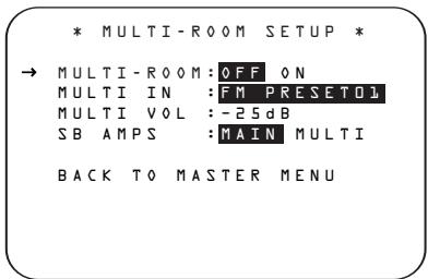
Figure 17
When the MULTI-ROOM menu appears, the on-screen cursor will be at the MULTI-ROOM line. Since this line is used to turn the system on and off, don't make an adjustment here unless you wish to turn the system on at this time. To turn the system on, press the Navigation Button 15 so that ON is highlighted. If you do not wish to turn the system on at this time or to proceed to the next step, press the Navigation Button 15 once so that the on-screen cursor is next to the MULTI IN line.
At the MULTI IN line, press the / Navigation Button 15 until the desired input to the multiroom system appears in the highlighted video. When the selection has been made, press the Navigation Button 15 once so that the on-screen cursor is next to the MULTI VOL line.
At the MULTI VOL line, press the Navigation Button 15 until the desired volume level for the multiroom system is entered. DO NOT use the regular volume control knobs for this setting. When all settings for the multiroom setup have been made, press the Navigation Button 15 until the on-screen cursor is next to the BACK TO MASTER MENU line. If you have no other adjustments to make, press the OSD Button 31 to exit the menu system.
Surround Amplifier Channel Assignment
The AVR 430 is equipped with seven full-power amplifier channels to allow for complete 7.1-channel operation without the need for additional external amplifiers. However, in some installations you may wish to use the traditional 5.1-channel configuration for the main listening room, which allows the surround back left/right amplifier channels to be used to power speakers placed in a remote zone location.
If you wish to use the Surround Back amplifier channels to power the remote zone, press the / Navigation Button 15 until the cursor is pointing to the SB AMPS line on the MULTI-ROOM SETUP menu. Press the / Navigation Button 15 until MULTI is highlighted in reverse video and press the Set Button 17.
Remember that once this setting is made, you will not be able to take advantage of any of the 6.1/7.1-channel decoding or processing modes, and that the speakers used for the remote zone must be connected to the Surround Back/Multiroom Speaker Outputs ⑩. The volume for these speakers is set by the multiroom system, as explained on this page.
Once this setting is made, you may press the / Navigation Button 15 to make any of the other adjustments available on this menu. If no other adjustments are needed, press the OSD Button 31 to exit the menu system.
Multiroom Operation
When operating the AVR 430 from a remote room location where an IR sensor link has been connected to the AVR 430's rear panel Multiroom IR Input 25, you may use either the main remote control or the Zone II remote. To turn on the multiroom feed, press the AVR Selector 5 E to turn the unit on to the last source, or any of the other Selector Buttons C D 4 34 44 to turn on to a specific source.
As long as an IR feed to the AVR 430 has been established from the remote room, using any of the buttons on either remote will control the remote location volume 18 , change the tuner frequency
23E, change the tuner preset 22G or mute the output 33
If the Remote IR Output Jack 27 on the AVR 430 is connected to an IR Input jack on compatible Harman Kardon audio components such as CD, DVD or cassette players, the transport functions of those machines may also be controlled using the Transport Controls 20 21 F G H J on either remote control.
To turn the system off from the remote room, press the Power Off Button 1 A. Remember that the AVR 430 may be turned on or off from the remote room, regardless of the system's operation or status in the main room.
NOTE: When the tuner is selected as the source for the remote zone, any change to the frequency or preset will also change the station being listened to in the main room, if the tuner is in use there. Similarly, if someone in the main room changes the station, the change will also have an impact on the remote room.
To turn on the Multiroom system from the main listening room, which is necessary before any A-BUS products connected to the AVR may be used, press the Multiroom Button 27 on the remote. When the MULTI ON/OFF message appears in the on-screen display and the Lower Display Line 14, press the Set Button 17 and then press the / Navigation Button 15 so that display changes to MULTI ON. Press the Set Button 17 again to activate the setting. Note that this method may be used to turn the Multiroom system on or off even when the AVR is in the Standby mode in the main listening room.
IMPORTANT NOTE: When an A-BUS module is connected, the AVR's Multiroom system must be turned on before the A-BUS module is able to communicate with the AVR. Once turned on using the instructions in the preceding paragraph, the Multiroom system must remain on in order for the A-BUS module to operate. When the unit is in the Standby mode, but ready for Multiroom or A-BUS operation, the lighting around the Standby/On Switch 1 remains blue and a MULTI ON message appears in the Lower Display Line 14, even though the unit is "off" in the main listening room.
When the Multiroom system is turned on, the input selected using the Multiroom menu will be fed to the Multiroom Audio Outputs 29 on the rear panel as well as the A-BUS Connector 5. The volume will be as set in the previous selection, although it may also be adjusted using an optional IR sensor and the Zone II remote in the remote location, or the A-BUS keypad, or on the optional audio power amplifier connected to the Multiroom Audio Outputs 29.
Although changes to the input source or remote room volume will normally be made using an IR sensor in the remote room that is connected to the AVR, it is also possible to change those settings from the main listening room. This is useful for situations where some or all of the remote rooms do not have an IR sensor, or to take control over the remote room without actually being in that room.
In addition to using the MULTIROOM menu, as shown on the previous page, you may change the source or volume in the remote zone using the remote. Press the Multiroom Button 27 on the remote, and when the MULTI ON/OFF message appears in the on-screen display and the Lower Display Line 14, press the Set Button 17 and then press the / Navigation Button 15 to toggle past that message to MULTI LEVEL or MULTI INPUT.
To change the remote room's input source, when MULTI INPUT appears, press the Set Button 17, and then press the / Navigation Button 15 until the desired input appears in the on-screen display and in the Lower Display Line 14. Remember that only analog or PCM input sources may be selected for use with the Multiroom system. Dolby Digital or DTS sources are not available to the Multiroom system.
To change the remote room's volume, when MULTI LEVEL appears, press the Set Button 17, and press the / Navigation Button 15 to change the volume setting. Note that this volume adjustment controls the level for the output to the Multiroom Audio Outputs 29 and for any speakers connected to the Surround Back/Multiroom Speaker Outputs 0 when the Surround Back amplifier channels are configured for Multiroom use, as shown on page 39. This adjustment does NOT
change the volume level for any room where an A-BUS module is used, as that setting is only adjustable using the A-BUS module's volume control or built-in IR sensor.
Once the Multiroom system is turned on, it will remain on even if the AVR 430 is placed in the Standby mode in the main room by pressing the Power Off Button or the Main Power Switch on the front panel.
The Multiroom system will remain on even if the unit is turned off in the main room. In that event, although front-panel indicators and the accent lighting around the volume control will turn off, a MULTI ON message will remain in the Lower Display Line 14 and the lighting around the Standby/On switch will remain blue when the unit is in the Standby mode in the main room to remind you that power is still applied to the unit, and that it is being used for Multiroom operation elsewhere in the house. Remember that if you turn the unit completely off by pressing the Main Power Switch A, the feed to the second zone will also be turned off.
When the AVR 430 is turned off in the main room, the Multiroom system may be turned on at any time by pressing the Multiroom Button 27, or any of the Selector Buttons B C D in the remote room.
The AVR 430 remote is factory-programmed for all functions needed to operate the unit. In addition, it is also preprogrammed to operate most recent Harman Kardon DVD players and changers, CD players and changers, CD recorders and cassette decks. The codes for other brand devices may be programmed into the AVR 430 remote using its extensive library of remote codes or a head-to-head learning process for codes not in the internal library.
Thanks to the remote's advanced technology and two-line LCD display, it is no longer necessary to look up cumbersome codes when programming the remote; following the steps outlined below, you simply search for the brand name from the remote's memory. We recommend that you first try the preprogrammed code entry method. If that procedure is not successful, then try the code-learning method.
Preprogrammed Code Entry
The easiest way to program the remote for operation with a source device from another brand is to follow these steps:
- Turn on the power to the device you wish to program into the AVR remote. This is important, as in a later step you will need to see whether the device turns off to determine whether the remote has been programmed for the proper remote codes.
- Press and hold the Program Button 25 for about three seconds while the message shown in Figure 18 appears in the remote's LCD Information Display 3. Release the button when the red light under the Set Button 17 appears.
HOLD PROGB BUTTON FOR 3 SECONDS
Figure 18
- The remote's MAIN MENU message (Figure 19), will appear in the LCD display and the Set Button 17 will remain illuminated in red. Press the Set Button 17 to begin the process of selecting a device and locating the proper remote codes.
MAIN MENU PROGRAM DEVICE
Figure 19
- SELECT A DEVICE will appear in the LCD display (Figure 20). Press the / Navigation Button to scroll through the list of device categories and press the Set Button when the device you wish to set the codes for appears. For this example, we will select "TV" to enter the codes needed to operate your TV.

Figure 20
NOTE: The codes for hard-drive recorder products (PVR) such as TiVo® and Replay TV® are programmed by selecting VCR as the device. For satellite-based TiVo products, check under the brand name of the product.
- At the next menu screen on the remote (Figure 21), press the Set Button to enter the Manual mode, which means that you will select the brand name of the device from the list programmed into the remote's memory.

Figure 21
- The next menu screen on the remote (Figure 22) will show the start of the list of available brands. Press the / Navigation Buttons until the brand name of the device you are programming into the remote appears on the lower line of the display and then press the Set Button

Figure 22
NOTE: If the brand name for the product you wish to program does not appear in the list, the codes may still be available, as some manufacturers share codes. If the desired brand is not listed, press the Clear Button 10 to exit the programming process, and skip to the instructions shown on page 42 for the "Automatic" method of programming the remote. If desired, or if the codes for your brand are not part of the remote's library at all, you may still use the remote to program most infrared-controlled products by "learning" the commands from the product's original remote into the AVR remote. The instructions for Learning Commands are on page 42.
- The next step is important, as it determines which codes will operate the source device or display. Point the AVR remote at the device being programmed and, following the instructions shown in the remote's LCD Information Display 3, press and release the Numeric Keys 11 shown on the menu screen (Figure 23) one at a time, starting with the "1" button. After you press the "1" Button 11, the remote's LCD screen will briefly go blank as the code is being transmitted, but you will see the "transmit" icon in the upper right corner of the display to serve as confirmation that the remote is sending out commands.

Figure 23
- After you press and release the number key, watch the device being programmed to see whether it turns off. As shown in the instructions that will appear on the next menu screen (Figure 24), if your device has turned off, press the Set Button 17, and then skip to Step 10. If the unit does not turn off, proceed to the next step.

Figure 24
- If the device being programmed into the AVR remote does not turn off after you have pressed the "1" Button ①, repeat Steps 7 and 8 by pressing the available numeric keys shown until the device turns off. If the device still does not turn off after all choices have been tried, or if there is only one number key shown as available to try, the code for this specific device is not in the AVR remote library under that brand name. If that is the case, press the Clear Button ⑩ to exit the manual programming mode. Remember that the codes may still be stored in the AVR remote's library under another brand, and you can have the remote control search for them by following the instructions below for automatic programming. You may also manually "learn" the codes for most devices into the AVR remote by following the Learning Commands instructions on page 42.
- When the device being programmed does turn off after a numeric key has been pressed, you must press the Set Button ⑰ within five seconds to enter the setting into the remote's memory. After you press the Set Button ⑰, the top line of the LCD display will read SAVING... and then the word SAVED will flash four times in the center of the bottom line.
- When the codes are saved, the remote will return to normal operation, and whenever you press the Input Selector Button 4 that was just programmed, the codes for the new device will be used. If no further buttons are pressed, the remote will revert back to the default setting for AVR commands.
NOTE: Some brands share a common remote control code for "Power Off" for many models. For that reason it is possible that even though the remote appears to be properly programmed, you may find that some buttons do not appear to issue the correct command. If this is the case, repeat the procedure outlined above, but if more than one numeric key selection is suggested in Step 7, try a different number to see whether the remote operates correctly. Although the AVR remote is preprogrammed with an extensive library of codes for many major brands, it is also possible that you may have attempted to program a product that is too new
or too old, and thus not all of its commands will be in the code library. You may fill in the codes for any button that does not operate properly by using the learning technique shown on this page.
Automatic Code Entry
In addition to manual code selection using the brand name list, it is also possible to automatically search through all the codes that are stored in the AVR remote's library to see whether a device will respond even if it is not listed among the brands that appear when you program the remote manually. To automatically search through the codes that are available for a specific device type (e.g., DVD, VCR), follow these steps:
- Turn on the power to the device you wish to program into the AVR remote. This is important because in a later step you will need to see whether the device turns off to determine whether the remote has been programmed for the proper remote codes.
- Press and hold the Program Button 25 for about three seconds while the message shown in Figure 18 appears in the remote's LCD Information Display 3. Release the button when the red light under the Set Button 17 appears.
- The remote's MAIN MENU message (Figure 19) will appear in the LCD display and the Set Button ⑦ will remain illuminated in red. Press the Set Button ⑦ to begin the process of selecting a device and locating the proper remote codes.
- SELECT A DEVICE will appear in the LCD display (Figure 20). Press the / Navigation Button to scroll through the list of device categories and press the Set Button when the device for which you wish to set the codes appears. For this example, we will select "TV" to enter the codes needed to operate your TV.
- At the next menu screen on the remote, press the Navigation Button 15 so that the bottom line of the LCD display reads AUTO (Figure 25) and then press the Set Button 17 to enter the Automatic programming mode.

Figure 25
- As instructed on the next menu screen, press the Navigation Button to begin the automatic code search process. Your confirmation that the remote is sending out commands is the movement of a square block across the top line of the LCD display screen while the bottom line reads PLEASE WAIT... You will also see the
transmit icon in the upper right corner of the LCD display's top line to remind you that the remote is working even though you may not see anything happening to the device being programmed.
- It will take a few seconds for the remote to send out the first group of commands, after which you will see a new display in the LCD screen, as shown in Figure 26. Following the instructions, if the device being programmed has not turned off, press the Navigation Button again to send another group of codes. If the device being programmed has turned off, skip to Step 9.
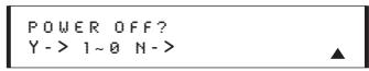
Figure 26
- By pressing the Navigation Button 15 again, the remote will send out a new set of commands. When it pauses, follow the instructions shown in Step 7. Depending on how many codes are stored for a specific device type, you may have to repeat this process as many as fifteen times. Remember, if the device turns off, skip to Step 9. When all the codes for the device being programmed have been tried, the instruction shown in Figure 27 will appear. This means that the codes for the product you are trying to program are not in the AVR remote library and you will have to "learn" them into the remote following the instructions shown in the next section. Press the Set Button 17 as instructed to exit the programming process.

Figure 27
- If the device being programmed does turn off after following the instructions in Step 7, you will need to verify the code set by pressing the Numeric Keys 11 in sequence, as instructed in Figure 26. Point the remote at the device being programmed, and press the "1" Button 11 to see whether the device turns back on.
- After pressing and releasing the "1" Button 11, check to see whether the device has turned back on. If it has, skip to Step 12. If it does not turn off, press the "2" Button 11, or the next button in the numeric sequence if you are repeating the procedure, as instructed by the LCD screen in Figure 28.

Figure 28
- When pressing the "1" button does not turn the device being programmed back on, repeat the procedure by trying the remainder of the
Numeric Keys in sequence, each time pressing and then releasing the button to see whether the new device turns back on. When it does, skip to the next step. However, if you try all 10 numeric keys and find that the unit will not turn on, you won't be able to use this method to program the device. Press the Clear Button to exit the programming process. You'll need to follow the Learning Commands instructions below to enter the codes for this device into the AVR remote.
- When pressing one of the numeric keys in Step 10 or 11 causes the device being programmed to turn back on, follow the instructions shown in Figure 26 and press the Set Button within five seconds of the device turning on. After you press the Set button, the top line of the LCD display will read SAVING... and then the word SAVED will flash four times in the center of the bottom line.
- When the codes are saved, the remote will return to normal operation, and whenever you press the Input Selector Button 4 that was just programmed, the codes for the new device will be used. If no further buttons are pressed, the remote will revert back to the default setting for AVR commands.
Learning Commands
On occasions when the AVR remote does not contain the codes for a particular product's remote in its built-in library, or when you wish to program a missing or special function into one button of a device, the AVR remote's learning capability allows you to do that. To teach commands from one product's remote into the AVR remote, follow the steps below:
The process requires that both the device's original remote and the AVR remote be available. Before pressing any buttons on either remote, place them so that the IR transmitter on the remote from the device to be programmed is facing the Infrared Lens 47 on the AVR remote. The two remotes should be no more than an inch apart, and there should not be any direct sunlight or other bright light source near the remotes.
- Press and hold the Program Button 25 for about three seconds while the message shown in Figure 18 appears in the remote's LCD Information Display 3. Release the button when the red light under the Set Button 17 appears.
- The remote's MAIN MENU message (Figure 19), will appear in the LCD display and the Set Button ⑦ will remain illuminated in red. Press the ▲ Navigation Button ⑤ once so that LEARN appears on the bottom line of the LCD
screen, as shown in Figure 29. Press the Set Button to begin the process of learning commands from another device's remote into the AVR remote.

Figure 29
- The SELECT A DEVICE message will appear in the LCD display (Figure 20). Press the / Navigation Buttons 15 to scroll through the list of device categories and press the Set Button 17 when the device for which you wish to set the codes appears. For this example, we will select "TV" to enter the codes needed to operate your TV.
- The next menu screen (Figure 30) will prompt you to select the button, or "key," on the AVR remote that you wish to program. Press that button on the AVR remote.

Figure 30
- Once you press the button to be programmed on the AVR remote, press and hold the button on the remote control for the device to be programmed within five seconds, as instructed on the next menu screen (Figure 31).

Figure 31
- Continue to hold the button on the original remote until the menu on the AVR remote's LCD screen changes. If the code is successfully learned, you will see the display shown in Figure 32. If you see that menu, proceed to Step 9. If the code is not successfully learned, you will see the display shown in Figure 33. If that menu appears, proceed to Steps 7 and 8.

Figure 32

Figure 33
-
If the message shown in Figure 33 appears in the display, press the Set Button to try programming the button again. When the remote prompts you to press and hold the key on the original remote again by showing the display shown in Figure 31, immediately press the button on the source remote again. To avoid another failed attempt, make certain that the windows on the two remotes are facing one another.
-
Continue to hold the button on the original remote until the LCD display changes again. If the code was successfully learned, you will see the display shown in Figure 32. In that case, go to Step 9. If the LEARN Failed display (Figure 33) appears again, you may either try to program the key again, or press the Navigation Button 15 to stop the process. It is possible that some remotes may use code sequences or infrared frequencies that are not compatible with the AVR remote, and those codes cannot be learned. When the display shown in Figure 34 appears, press the Set Button 17 to exit the Learning system.

Figure 34
- When a code has been learned successfully, you have three options. When the display shown in Figure 31 is on the LCD screen on the AVR remote, you may press the Set Button to learn additional codes from the buttons on a source remote into the AVR remote. Follow Steps 4 through 6 as often as needed to complete the code-learning process.
- If you wish to change the name that appears in the LCD display when the button that has just had a new code learned is pressed, press the Navigation Button 15 so that the display shown in Figure 34 appears in the LCD display. Press the Set Button 17 to be taken to a RENAME KEY display. Enter the new name for the key following the instructions shown in the Renaming Individual Keys section of this manual on page 49. If you find it more convenient to rename the buttons at a later time, you may do that separately by following the instructions on page 49.

Figure 35
- When you have programmed all keys for the desired device, press the Navigation Button 15 twice when the LEARN MENU (Figure 32) appears so that you see the display shown in Figure 36. Press the Set Button 17 to return the remote to normal operation.

Figure 36
- If you wish to program the codes for another device, repeat the procedure outline above, but select a different device in Step 3.
Changing Devices
In the factory default settings, the AVR remote is programmed so that the commands transmitted correspond to the device selected by pressing one of the Input Selectors 4. This is logical, as you want the remote to control the device you have selected. However, in some circumstances you may have configured your system so that the devices connected to the AVR 430 do not correspond to the default device settings and the legends printed on the remote. For example, if your system has two VCRs you may connect the second VCR to the VID 2 input. There is no problem in doing that, but in normal operation the commands issued after selecting the VID 2 input are for a television, not a VCR.
The AVR remote allows you to correct that situation through the "Changing Devices" process. This enables you to assign the codes from one type of device to a different button. For example, in the steps below, we will explain how to program the VID 2 buttons to provide the commands to operate a VCR. Of course, you may program the remote to have any of the devices take on the code set of any other device, as your system requires. And, with the AVR remote's "Rename" function, you can even change the way the name of the device appears on the remote's LCD display so that you see exactly which commands are being sent. (See page 48.)
To program the buttons normally assigned to one device for the commands of another, follow these steps:
- Press and hold the Program Button 25 for about three seconds while the message shown in Figure 18 appears in the remote's LCD Information Display 3. Release the button when the red light under the Set Button 17 appears.
- The remote's MAIN MENU message (Figure 19), will appear in the LCD display and the Set Button ⑦ will remain illuminated in red. Press the ▲ Navigation Button ⑤ twice so that CHANGE DEVICE appears on the bottom line of the LCD screen, as shown in Figure 37. Press the Set Button ⑦ to begin the process of reassigning the commands used for a particular device.

Figure 37
- The next menu display is where you select the Input Select, or device, that you wish to change. When the display shown in Figure 38 appears, press the / Navigation Button 15 to scroll through the list to find the device you wish to use for another function. In this case we will select
"TV," and show how to change it to take on the codes for operating a VCR. When that device's name appears, press the Set Button 17.

Figure 38
- Once the "old" device type has been selected, you need to tell the remote which set of remote codes to use as a replacement for the device just selected. When the instructions shown in Figure 39 appear, press the / Navigation Button 15 to scroll through the list of device categories to find the name of the device that you wish to use. The old device name will remain on the left side of the LCD screen, while the replacement device list will scroll to its right. For example, press the Navigation Button 15 until the display screen reads TV<-VCR to have the VID 2/TV Button transmit the commands used to control a VCR. Press the Set Button 17 when the desired device combination appears.

Figure 39
-
Once the new device is selected, the remainder of the process will select the codes for the specific brand to be used, and for that reason they are identical to the way a device is programmed using manual entry. Continue the process as outlined in the next few steps, remembering that if the codes for your specific device are not found, you may select any brand and then "learn" the proper codes into the AVR remote using the process outlined on page 42. To begin the process, start by selecting the brand of device, as shown in Figure 22. Press the / Navigation Button until the brand name of the device you are programming into the remote appears on the lower line of the display and then press the Set Button 17.
-
The next step is important, as it determines which codes will operate the source device or display. Point the AVR remote at the device being programmed and, following the instructions shown on the remote's LCD Information Display 3, press and release the Numeric Keys 1 one at a time, starting with the "1" Button 1. After you press the "1" Button 1, the remote's LCD screen will briefly go blank as the code is being transmitted, but you will see the "transmit" icon in the upper right corner of the display to serve as confirmation that the remote is sending out commands.
-
After you press and release the number key, watch the device being programmed to see whether it turns off. As shown in the instructions that will appear on the next menu screen (Figure 24), press the Set Button 17, and then skip to Step 9. If the unit does not turn off, proceed to the next step.
- If the device being programmed into the AVR remote does not turn off after you have pressed the "1" Button 11, continue Steps 6 and 7 by pressing the available numeric keys shown until the device turns off. If the device still does not turn off after all choices have been tried, the code for this specific device is not in the AVR remote library under that brand name. If that is the case, we suggest that you press the Set Button 17 to accept the codes from another brand so that the programming is completed, but remember that you will then have to program the remote manually by following the Learning Commands instructions on page 42.
- When the device being programmed does turn off after a numeric key has been pressed, you must press the Set Button ⑦ within five seconds to enter the setting into the remote's memory. After you press the Set button, the top line of the LCD display will read SAVING... and then the word SAVED will flash four times in the center of the bottom line.
- When the codes are saved the remote will return to normal operation, and whenever you press the Input Selector Button 4 that was just programmed, the display will show the original device type code at the far left side of the display, with the name of the new code set type in brackets. For example, the display will read TV<-VCR in our example of replacing the TV codes with those for a VCR.
Macro Programming
Macros enable you to easily repeat frequently used combinations of multiple remote control commands with the touch of a single button. Once a macro is programmed, you may send up to 20 commands with one press of the Power On or Macro buttons. This will greatly simplify the process of turning on your system, changing devices or other common tasks. Thanks to the remote's two-line display, it is easier than ever for you to take advantage of the power of macro commands.
Recording a Macro
To record a macro into the remote's memory, follow these steps:
- Press and hold the Program Button 25 for about three seconds while the message shown in Figure 18 appears in the remote's LCD Information Display 3. Release the button when the red light under the Set Button 17 appears.
- The remote's MAIN MENU message (Figure 19), will appear in the LCD display and the Set Button ⑦ will remain illuminated in red. Press the ▲ Navigation Button ⑤ three times so that MACRO appears on the bottom line of the LCD screen, as shown in Figure 40. Press the Set Button ⑦ to enter the main macro menu branch.

Figure 40
- At the next menu screen (Figure 41) press the Set Button to begin recording a macro.

Figure 41
- The next display screen (Figure 42) is where you select the button that will be used to recall the macro. The choices are the Power On Button 2 or one of the discrete Macro Buttons 28. Press the / Navigation Button 15 until the name of the button you wish to program the macro into is shown. For this example we will show how to program a series of commands that will automatically be sent out every time the Power button is pressed.

Figure 42
- The next screen that appears (Figure 43) is where you select the device for the first command that will be sent out as part of the macro. Press the / Navigation Button until the name of the device appears on the left side of the lower line in the LCD display. For this example, the first button we want to have the macro "press" is the Power On button, so the AVR device is selected. Press the Set Button when the desired device name appears to move to the next programming step.

Figure 43
- The next display (Figure 44) is where you begin entering the individual commands for the macro, in the order you wish them to be transmitted. Remember that when you want to change devices,
you must first press the Input Selectors 4 for that button, and then press the Command or Function key. Since we want to program a series of events that occur each time the Power On button is pressed, press the AVR button. In your specific macro, this is the first command button.
SELECT A DEVICE
AVR
Figure 44
- The next display (Figure 45) and the subsequent screens are where the actual macro programming takes place. The words at the left side of the top line of the display show the button that is being programmed (e.g., the Power On Button 2 or one of the Macro Buttons 23) and the indication at the right side of the top line shows the number of macro steps available of 20 possible steps. Following the instructions on the remote's LCD screen, press the first key you wish to be transmitted in the macro. In our example, we first want the AVR 430 to turn on, so the Power Button 2 should be pressed.
POWER ON 00/20 SELECT KEY PRESS
Figure 45
- Once the first command button for the macro has been pressed, continue to press the buttons you wish to be part of the macro, in the order they will be used. Press each button within five seconds of the last button, remembering to press the Input Selector 4 when you are changing device functions. As the buttons on the remote are pressed, the remote's display screen will show the steps in the macro as they are programmed (Figure 46).
- For our example, we first want the AVR Power On button pressed, followed by the TV Power On, followed by the Cable Box On, followed by the selection of the Logic 7 mode. To do that, press the buttons in this order:
Power On 2
VID 2/TV 4
Power On 2
VID 3/Cable 4
Power On 2
- AVR 5
- Logic 7 8
As each button is pressed to enter it into the macro, you will see the button names appear and then scroll up on the LCD display as your confirmation of the key entry (Figure 46).
- When all commands for the macro have been entered, press the Set Button 17 to save the macro. The display screen will show the button to which the macro has been programmed and the number of steps used, and the word SAVED will blink four times in the lower line of the LCD display. When the display returns to normal, the macro has been entered and the remote is ready for operation.
- If a macro has been programmed into the Power On Button 2, it will play back anytime the Power On button is pressed. As the macro plays, you will see the steps appear in the remote's LCD display. Macros programmed into one of the four discrete Macro buttons may be activated at any time by pressing the appropriate button.
Erasing a Macro
Once a macro has been created and stored in the AVR remote's memory, you have the option of erasing it. You may do this at any time by following these steps:
- Press and hold the Program Button 25 for about three seconds while the message shown in Figure 18 appears in the remote's LCD Information Display 3. Release the button when the red light under the Set Button 17 appears.
-
The remote's MAIN MENU message (Figure 19), will appear in the LCD display and the Set Button ⑦ will remain illuminated in red. Press the ▲ Navigation Button ⑤ three times so that MACRO appears on the bottom line of the LCD screen, as shown in Figure 40. Press the Set Button ⑦ to enter the main macro menu branch.
-
At the next menu screen (Figure 47), press the / Navigation Button until the bottom line in the remote's LCD display reads ERASE A MACRO. Press the Set Button to begin the process of erasing a macro.

Figure 47
- The next display screen (Figure 48) is where you select which macro will be erased. Press the Navigation Button until the number of the macro you wish to erase appears. For this example we will erase the Power On macro created in the previous section. When the name of the macro to be erased appears, press the Set Button

Figure 48
- The word ERASED will flash four times in the bottom line of the remote's LCD display, and then the display will return to its normal condition. When that happens, the macro is erased and the remote is returned to normal operation.
Read a Macro
To check the commands stored in the remote's memory for one of the buttons, follow these steps:
- Press and hold the Program Button 25 for about three seconds while the message shown in Figure 18 appears in the remote's LCD Information Display 3. Release the button when the red light under the Set Button 17 appears.
- The remote's MAIN MENU message (Figure 19), will appear in the LCD display and the Set Button ⑦ will remain illuminated in red. Press the ▲ Navigation Button ⑤ three times so that MACRO appears on the bottom line of the LCD screen, as shown in Figure 40. Press the Set Button ⑦ to enter the main macro menu branch.
- At the next menu screen (Figure 49), press the / Navigation Button until the bottom line in the remote's LCD display shows READ A MACRO. Press the Set Button to begin the process of reading a macro.

Figure 49
- The next display screen (Figure 50) is where you select the macro to be read. Press the / Navigation Button until the name of the macro you wish to read appears. For this example, we will read back the Power On macro created in a previous section. When the name of the macro to be read appears, press the Set Button

Figure 50
- As soon as the Set button is pressed, the first two steps in the macro will be appear in the remote's LCD screen. You may then use the / Navigation Button 15 to step up or down through the list of commands stored as the macro. As you read the display, you will see Input Selector Buttons 4 appear in brackets, (e.g., [AVR]). When the step in the macro is a function, navigation or any other button, it will appear
next to the bracketed read-out of the underlying device (e.g., [AUR] POWER ON).
- When you are finished reviewing the macro's contents, press the Set Button 17 to return the remote to normal operation.
Punch-Through Configuration
Punch-through is a capability of the remote that allows the Volume controls, Channel Up/Down buttons or Transport keys (Play, Stop, Record, Fast Forward and Reverse, and Skip Up/Down) to link to a different device. For example, if your TV, cable box or satellite receiver is connected through the AVR 430, you will most likely want to use the AVR 430's volume control commands even when the remote has been set to issue all other commands for the video device. "Punch-through" enables you to easily program the remote to do this.
Volume Punch-Through
Follow these steps to enable the Volume Up/Down and Mute controls from one device to be used when the remote is otherwise programmed for a different device.
NOTE FOR VOLUME PUNCH-THROUGH: The
remote's default settings are for the AVR 430's volume controls, to be used when any input or device is selected, with the exception of the VID 2/TV button. There is no need to program the remote for volume punch-through for the AVR 430's controls with other sources, such as DVD. To have the AVR 430's volume commands used when the TV device is selected, follow these steps:
- Press and hold the Program Button 25 for about three seconds while the message shown in Figure 18 appears in the remote's LCD Information Display 3. Release the button when the red light under the Set Button 17 appears.
- The remote's MAIN MENU message (Figure 19), will appear in the LCD display and the Set Button ⑦ will remain illuminated in red. Press the ▲/▼ Navigation Button ⑤ until PUNCH-THROUGH appears on the bottom line of the LCD screen, as shown in Figure 51. Press the Set Button ⑦ to enter the main punch-through menu branch.

Figure 51
- At the next menu screen (Figure 52) press the Set Button to begin programming the remote for Volume punch-through.

Figure 52
- The next display screen (Figure 53) is where you select the device that will receive the punchthrough commands. In our example, that is the VID 2/TV button, as that is where we want the AVR 430's volume controls to be active. Press the / Navigation Button until the name of the base device appears and then press the Set Button

Figure 53
- At the next display screen (Figure 54), you will select the device whose Volume Up/Down and Mute commands will be used. Press the Navigation Button until the desired device's name appears to the right of the device in use. In our example, that is the AVR 430 (indicated by AVR). When the desired combination of devices appears, press the Set Button

Figure 54
- When the Set button is pressed, the display will change to show you that the new combination of control commands is being saved to the unit's memory, as shown in Figure 55. The word SAVED will flash four times and then the remote will return to normal operation.

Figure 55
- Once the punch-through is programmed, the Volume Up/Down and Mute buttons of the second device named will be used when those buttons 13 33 are pressed while the master device is in use.
Returning the Volume Control Settings to Default Operation
If you wish to remove the Volume punch-through so that the commands for Volume and Mute are returned to the factory default setting, follow the steps shown above, except that in Steps 4 and 5, select the same device for both the DEVICE IN USE on the left side of the bottom line and the PUNCH-THROUGH device. In the example used, the display to return the remote to default settings will appear as shown in Figure 56.

Figure 56
Channel Punch-Through
Channel punch-through allows the Channel Up/Down buttons to send commands to a different device than the one that has been selected for other commands. For example, you may wish to use a cable box or satellite receiver as the source for a VCR, so you would want the Channel Up/Down Buttons 35 to transmit commands to the cable box even though the other button commands are programmed to operate the VCR.
To program the remote for Channel punch-through, follow these steps. This example will show how to program channel punch-through so that the commands programmed for Channel Up/Down for the VID 3/Cable device will be transmitted when the VID 1/VCR device has been selected as the current device.
- Press and hold the Program Button 25 for about three seconds while the message shown in Figure 18 appears in the remote's LCD Information Display 3. Release the button when the red light under the Set Button 17 appears.
- The remote's MAIN MENU message (Figure 19), will appear in the LCD display and the Set Button ⑦ will remain illuminated in red. Press the ▲/▼ Navigation Button ⑤ until PUNCH-THROUGH appears on the bottom line of the LCD screen, as shown in Figure 51. Press the Set Button ⑦ to enter the main punch-through menu branch.
- At the next menu screen, press the / Navigation Button 15 until CHANNEL appears on the bottom line of the LCD screen, as shown in Figure 57. Press the Set Button 17 to begin programming the remote for Channel punch-through.

Figure 58
Figure 57
-
The next display screen (Figure 58) is where you select the device that will receive the punchthrough commands. In our example, that is the VID 2/TV button, as that is where we want the cable box's channel controls to be active. Press the Navigation Button until the name of the base device appears and then press the Set Button
-
At the next display screen (Figure 59), you will select the device whose Channel Up/Down commands will be used. Press the / Navigation
Button 15 until the desired device name appears to the right of the device in use. In our example, that is the cable box. When the desired combination of devices appears, press the Set

Button 17
Figure 59
- When the Set button is pressed, the display will change to show you that the new combination of control commands is being saved to the unit's memory, as shown in Figure 60. The word SAVED will flash four times and then the remote will return to normal operation.

Figure 60
- Once the punch-through is programmed, the Channel Up/Down Buttons of the second device named will be used when those buttons are pressed while the master device is in use.
Returning the Channel Control Settings to Default Operation
If you wish to remove the Channel Punch-Through so that the commands for Channel Up/Down are returned to the factory default setting, follow the steps shown above, except that in Steps 4 and 5, select the same device for both the DEVICE IN USE on the left side of the bottom line and the PUNCH-THROUGH device. In the example used, the display to return the remote to default settings will appear as shown in Figure 61.

Figure 61
Transport Punch-Through
The Play 36, Stop 20, Fast Forward/Reverse 19, Pause 20, Record 20 and Skip Up/Down 21 Transport Controls are set at the factory to operate your DVD player, or the controls of a specific device such as a VCR or CD player when they are selected. However, by using the Transport Punch-Through feature you may program these controls to transmit the commands for a different device. For example, you may wish to operate the transport of a second VCR connected to the VID 2/TV input, as shown in the following example.
- Press and hold the Program Button 25 for about three seconds while the message shown in Figure 18 appears in the remote's LCD Information Display 3. Release the button
when the red light under the Set Button 17 appears.
- The remote's MAIN MENU message (Figure 17), will appear in the LCD display and the Set Button ⑦ will remain illuminated in red. Press the ▲/▼ Navigation Button ⑤ until PUNCH-THROUGH appears on the bottom line of the LCD screen, as shown in Figure 51. Press the Set Button ⑦ to enter the main punch-through menu branch.
- At the next menu screen, press the / Navigation Button 15 until TRANSPORT appears on the bottom line of the LCD screen, as shown in Figure 62. Press the Set Button 17 to begin programming the remote for transport punch-through.

Figure 62
- The next display screen (Figure 63) is where you select the device that will receive the punchthrough commands. In our example, that is the TV button, as that is where we want the VCR's transport controls to be active. Press the / Navigation Button until the name of the base device appears and then press the Set

Button 17
Figure 63
- At the next display screen (Figure 64), you will select the device whose transport commands will be used. Press the / Navigation Button until the desired device name appears to the right of the device in use. In our example, that is the VCR. When the desired combination of devices appears, press the Set Button

Figure 64
- When the Set button is pressed, the display will change to show you that the new combination of control commands is being saved to the unit's memory, as shown in Figure 65. The word SAVED will flash four times and then the remote will return to normal operation.

Figure 65
- Once the punch-through is programmed, the transport buttons of the second device named
will be used when those buttons are pressed while the master device is in use.
Returning the Transport Control Settings to Default Operation
If you wish to remove the Transport Punch-Through so that the transport commands are returned to the factory default setting, follow the steps shown above, except that in Steps 4 and 5, select the same device for both the DEVICE IN USE on the left side of the bottom line and the PUNCH-THROUGH device. In the example used, the display to return the remote to default settings will appear as shown in Figure 66.

Figure 66
EzSet Configuration
Harman Kardon's patented EzSet feature makes it easier than ever to calibrate the output levels on your new receiver for maximum playback accuracy. In addition to automatically setting the levels, the AVR remote's LCD display allows the unit to be used as a direct read-out SPL meter. Complete instructions for using the EzSet features of the AVR remote are found on pages 26 - 28 of this owner's manual.
In most cases you will find it easier to access the EzSet capabilities directly by pressing the SPL Select Button 45 and following the menu prompts as detailed on pages 27 and 28. However, there is one function of the remote that is only available through the remote's menu system being described in this section.
To avoid having the calibration settings created with EzSet changed accidentally, the remote allows you to disable the SPL Select Button 45 on the remote. To de-activate the button, follow these steps:
- Press and hold the Program Button 25 for about three seconds while the message shown in Figure 18 appears in the remote's LCD Information Display 3. Release the button when the red light under the Set Button 17 appears.
- The remote's MAIN MENU message (Figure 19), will appear in the LCD display and the Set Button ⑦ will remain illuminated in red. Press the ▲/▼ Navigation Button ⑤ until SET SPKR LEVELS appears on the bottom line of the LCD screen, as shown in Figure 67. Press the Set Button ① to enter the main EzSet menu branch.

Figure 67
- At the next menu screen (Figure 68) press the
/ Navigation Buttons 15 once so that EZSET DISABLE appears in the lower line of the LCD display.
SET SPKR LEVELS EzSET DISABLE
Figure 68
- Within five seconds, press the Set Button 17 to disable the SPL Select Button 45. Once the Set Button 17 is pressed the word EXITING will flash four times in the lower line of the LCD display and then it will return to normal operation.
Once these steps are completed, when the SPL Select Button 45 is pressed the remote will show EZSET DISABLE and it will not be activated.
To restore the EzSet feature to normal operation, repeat the procedure outlined above, except that in Step 3 you should press the / Navigation Button 15 so that EzSet ENABLE appears in the lower line of the LCD display. When that display appears, press the Set Button 17 and the EzSet feature will be reactivated. You may then press the Clear Button 10 to exit the remote's menu system and return to normal operation or press the Set Button 17 again to immediately use the EzSet feature to calibrate the system as shown on pages 27 and 28.
Renaming
While the names given to the buttons and inputs on the remote represent recognizable categories of audio/video products, system operation may be easier if the displays shown in the remote's LCD screen are customized to reflect the specific characteristics of a playback source's brand name or the new function given to a specific button when one remote's controls are programmed into the AVR remote. The AVR remote allows you to change the name of either a master device or any button on the remote using the following steps.
Renaming a Device
To rename a specific device/Input source button, follow these steps. For this example, we will show you how to rename the Device/Input Selector normally shown as "TV" to "HDTV TUNER."
-
Press and hold the Program Button 25 for about three seconds while the message shown in Figure 18 appears in the remote's LCD Information Display 3. Release the button when the red light under the Set Button 17 appears.
-
The remote's MAIN MENU message (Figure 19), will appear in the LCD display and the Set Button
17 will remain illuminated in red. Press the Navigation Button 15 until RENAME appears on the bottom line of the LCD screen, as shown in Figure 69.

Figure 69
- At the next menu screen press the / Navigation Button 15 until RENAME DEVICE appears on the bottom line of the LCD screen, as shown in Figure 70. Press the Set Button 17 to begin renaming a device.

Figure 70
- The next display screen (Figure 71) is where you select the device that will be renamed. In our example, that is the TV button. Press the / Navigation Button until the name of the base device appears and then press the Set Button

Figure 71
-
At the next menu screen you will see the device name on the bottom line of the display with a blinking cursor box to the right of the device name. Press the Navigation Button 15 to return the blinking cursor to the far left side of the display line. You may then retitle the device name as shown in the next step.
-
To enter the new name, press the Numeric Keys 11. The letters above the numbered buttons indicate which letter or symbol will appear when the button is pressed during the renaming process. The first press of the button will enter the first letter shown, subsequent presses of the same button will change the display to the other letters above that numbered key. For example, since the first letter we need to rename the input to HDTV Tuner is an "H", you would locate the "H" above the "4" button, and press the button twice. The first press shows a "G," the second press changes it to an "H." Consult the table at the end of this section to see which characters pressing a particular button generates.
-
After you enter the first letter of the new device name, there are three options for entering the next character:
a. To enter a letter that requires a different numeric key to be pressed, simply press that
button. The cursor will automatically move to the next position and the first letter accessed by the new button will appear. Following our example, the next letter needed is a "D", so you would press the "3" button once.
b. To enter a letter that uses the same numeric key, you must first press the Navigation Button to move the blinking cursor block to the next position. Then press the Numeric Key as required to enter the desired letter.
c. To enter a blank space, press the Navigation Button twice. The first press will move the cursor to the right, and the second press will move the cursor one more space to the right, leaving a blank space between the last letter and the next one.
-
Repeat Step 7 as needed to enter all the needed letters, numbers, characters and spaces.
-
When the text entry is complete, press the Set Button 17. The LCD display will blink DEVICE RENAMED three times and then return to normal operation.
Once a device is renamed you will see the new name on the top line of the remote's LCD display whenever the Input//Device Selector 4 is pressed, or when any other command/function button on the remote is pressed after the main Device Selector is pressed. Note that renaming a device in the remote will not change the name of the input used by the on-screen menu system of the AVR 430.
NOTES ON RENAMING DEVICES:
- To move the cursor to the right or left of the display during the renaming process, press the Navigation Buttons 15 as required.
- The table below shows the letters, numbers and characters that may be accessed by pressing the Numeric Keys:
| Key | Characters | Key | Characters |
| 1 | [.,/,1 | 6 | M,N,O,6 |
| 2 | A,B,C,2 | 7 | P,Q,R,S,7 |
| 3 | D,E,F,3 | 8 | T,U,V,8 |
| 4 | G,H,I,4 | 9 | W,X,Y,Z,9 |
| 5 | J,K,L,5 | 0 | - ,,#,0 |
- Renaming a device changes the name of the device only, not any of the individual key functions within that device memory. To change the name of an individual device, follow the instructions in the next section.
Renaming Individual Keys
Thanks to the programming flexibility of the AVR remote, an individual button on the remote may be assigned a feature or function that is different from the name that appears as the factory default when the button is pressed. However, with the Rename Key function it is possible to rename almost any button on the remote so that when the button is pressed you will see a more descriptive or appropriate name displayed.
To rename a specific button on the remote, follow these steps. For this example, we will show you how to rename the DSP Surround Mode Selector ⑦, which is normally not used when DVD is selected, so that it reads ZOOM in the remote's display.
- Press and hold the Program Button 25 for about three seconds while the message shown in Figure 18 appears in the remote's LCD Information Display 3. Release the button when the red light under the Set Button 17 appears.
- The remote's MAIN MENU message (Figure 17), will appear in the LCD display and the Set Button ⑦ will remain illuminated in red. Press the ▲/▼ Navigation Button ⑤ until RENAME appears on the bottom line of the LCD screen, as shown in Figure 69.
- At the next menu screen press the / Navigation Button 15 until RENAME KEY appears on the bottom line of the LCD screen, as shown in Figure 72. Press the Set Button 17 to continue.

Figure 72
- The next display screen (Figure 73) is where you select the device within which the key to be renamed exists. Press the / Navigation Buttons until the name of the base device appears. In our example, since we want to rename a button within the DVD device memory, DVD should appear in the lower line of the LCD. When the desired device name appears, press the Set Button

Figure 73
- At the next menu screen you will select the first button within the device to be renamed, as instructed in the display shown in Figure 74. Select the button by simply pressing it on the remote.
SELECT A KEY
Figure 74
- Depending on whether or not the button pressed already has a named function within the device selected, one of two things will happen.
a. If the button to be renamed already has a preprogrammed, or previously renamed title in the remote's memory, you will see that name on the top line of the LCD display, and a blinking block cursor will appear on the far left side of the bottom line of the display, as shown in Figure 75.

Figure 75
b. If the button to be renamed does not have a function in the device selected, the top line of the LCD screen will be blank, and a blinking block cursor will appear on the far left side of the bottom line of the display, as shown in Figure 76.

Figure 76
-
To enter the new name for the key, press the Numeric Keys 11. The letters above the numbered buttons indicate which letters or symbols will appear when the button is pressed during the renaming process. The first press of the button will enter the first character shown, subsequent presses of the same button will change the display to the other letters above that numbered key. For example, since the first letter we need to rename the Tone button to Zoom is a "Z," so you would locate the "Z" above the "9" button, and press the button four times. The first press shows a "W," the subsequent presses step through the other letters available until the "Z" appears. Consult the table on this page to see which characters are available by pressing a particular button.
-
After you enter the first letter of the new device name, there are three options for entering the next character:
a. To enter a letter that requires a different numeric key to be pressed, simply press that button. The cursor will automatically move to the next position and the first letter accessed by the new button will appear. Following our example, the next letter needed is an "0", so you would press the "6" button once.
b. To enter a letter that uses the same numeric key, you must first press the Navigation Button 15 to move the blinking cursor block to the next position. Then press the Numeric Key 11 as required to enter the desired letter. This is the way you would enter the second "O" in the word ZOOM, and again for the letter "M."
c. To enter a blank space, press the Navigation Button 15 twice. The first press will move the cursor to the right, and the second press will move the cursor one more space to the right, leaving a blank space between the last letter and the next one.
9. Repeat Steps 7 and 8 as needed to complete entering the needed letters, numbers, characters and spaces.
10. When the text entry is complete, press the Set Button ①. The new name will be entered into the remote's memory, replacing the default name.
11. At this point you have two options:
a. If you wish to program an additional key within the same device, press the Set Button 17 as instructed by the bottom line of the LCD display reading ANOTHER KEY. The remote will return to the SELECT A KEY menu option as shown in Step 6. Repeat the instructions in Steps 6 though 11 to rename the next key.
b. If you have no additional keys to rename, press the Navigation Button 15 once so that the menu screen displays EXIT on the bottom line of the display. Press the Set Button 17 to return the remote to normal operation.
NOTES ON RENAMING KEYS:
- Renaming a key does not change its function. You may change the function of an individual key by learning a new code into the remote. See page 42 for more information.
- When a key is renamed it will only apply to the specific device selected in Step 4. The same key may be renamed as needed for each individual device with which it is used.
Resetting the Remote
Depending on the way in which the remote has been programmed, there may be a situation where you wish to totally erase all changes that have been made to the remote and return it to the factory defaults. You may do that by following the steps shown below, but remember that once the remote is reset, ALL changes that have been made, including programming for use with other devices, learned keys, macros, punch-through settings and key names, will be erased and
any settings you had previously made will have to be reentered.
To erase all settings and reset the remote to the original factory default settings and displays, follow these steps:
- Press and hold the Program Button 25 for about three seconds while the message shown in Figure 18 appears in the remote's LCD Information Display 3. Release the button when the red light under the Set Button 17 appears.
- The remote's MAIN MENU message (Figure 19), will appear in the LCD display and the Set Button ⑦ will remain illuminated in red. Press the ▲/▼ Navigation Button ⑤ until USER RESET appears on the bottom line of the LCD screen, as shown in Figure 77.

Figure 81
Figure 77
- Press the Set Button to reset the remote. Note that once the Set Button is pressed the process may not be stopped. While the remote's memory is being cleared, a RESETTING... message will appear in the upper line of the remote's LCD screen as shown in Figure 78. It may take a few minutes for the reset process to take place, and the length of time will vary depending on how much customization and programming has taken place. Please be patient; as long as the message appears in the display the remote is functioning properly.
RESETTING...
Figure 78
- When the remote has been totally reset and returned to the factory default condition, a REMOTE RESET COMPLETE message will appear (Figure 79) briefly, and then the remote will return to normal operation.
REMOTE RESET COMPLETE
Figure 79
Additional Notes on Configuring and Operating the Remote
- When the remote is being programmed, it will automatically time-out if no button is pressed within a thirty-second period. The message shown in Figure 80 will appear briefly, and the remote will then exit the feature being programmed and any data entered will be lost.
TIMEOUTOR CLR KEY PRESSED
Figure 80
- The programming or configuration process may also be stopped at any time by pressing the Clear Button 10. The message shown in Figure 80 will appear, the data entered in the current process will be lost and the remote will return to normal operation. Any process that was underway when the button will be pressed must be restarted.
- Extensive use of the programming, learning and configuration functions of the remote may consume significantly more battery power than normal remote operation. While the batteries should last for four to six months in normal operation, you may find that they need to be changed sooner after the remote is programmed for the first time.
- When the batteries approach a level below which the remote will not function, the remote's LCD screen will display a LOW BATTERY warning as shown in Figure 81. We strongly recommend replacing the batteries as soon as this message appears to avoid the loss of programming and configuration settings. These settings are not lost when the batteries are changed quickly.
AUR LOW BATTERY
- The remote has a built-in backlight that may be activated by pressing the Light Button 25. This button is made from a special "glow" material so that it is easier to find in dark rooms. This glow feature does not consume any electricity, but the glow will fade when the remote is kept in a dark location for an extended period of time. The "glow" feature may be restored by placing the remote in normal room light for a few hours.
- The remote's backlight will remain lit for approximately five seconds after the Light Button 26 is pressed, and it will stay lit for another five seconds if any key is pressed while the backlight is on. You may keep the backlight lit by holding the Light Button, but extensive use of the backlight will reduce battery life.
- The LCD display will remain on for ten seconds after a key is pressed and then turn off to conserve battery life.
- When any button is held for more than thirty seconds, the LCD will turn off and the remote will stop transmitting the codes to conserve battery life.
| SYMPTOM | CAUSE | SOLUTION |
| Unit does not function when Main Power Switch is pushed | • No AC Power | • Make certain AC power cord is plugged into a live outlet • Check to see whether outlet is switch-controlled |
| Display lights, but no sound or picture | • Intermittent input connections • Mute is on • Volume control is down | • Make certain that all input and speaker connections are secure • Press Mute Button • Turn up volume control |
| Unit turns on, but front-panel display does not light up | • Display brightness is turned off | • Follow the instructions in the Display Brightness section on page 37 so that the display is set to VFD FULL |
| No sound from any speaker, light around power switch is red | • Amplifier is in protection mode due to possible short • Amplifier is in protection mode due to internal problems | • Check speaker wire connections for shorts at receiver and speaker ends • Contact your local Harman Kardon service center |
| No sound from surround or center speakers | • Incorrect surround mode • Input is monaural • Incorrect configuration • Stereo or Mono program material | • Select a mode other than Stereo • There is no surround information from mono sources • Check speaker mode configuration • The surround decoder may not create center- or rear-channel information from non-encoded programs |
| Unit does not respond to remote commands | • Weak batteries in remote • Wrong device selected • Remote sensor is obscured | • Change remote batteries • Press the AVR selector • Make certain front-panel sensor is visible to remote or connect remote sensor |
| Intermittent buzzing in tuner | • Local interference | • Move unit or antenna away from computers, fluorescent lights, motors or other electrical appliances |
| Letters flash in the channel indicator display and digital audio stops | • Digital audio feed paused | • Resume play for DVD • Check that Digital Input is selected |
In addition to the items shown above, additional information on troubleshooting possible problems with your AVR 430, or installation-related issues, may be found in the list of "Frequently Asked Questions" which is located in the Product Support section of our Web site at www.harmankardon.com.
Processor Reset
In the rare case where the unit's operation or the displays seem abnormal, the cause may involve the erratic operation of the system's memory or microprocessor.
To correct this problem, first unplug the unit from the AC wall outlet and wait at least three minutes. After the pause, reconnect the AC power cord and check the unit's operation. If the system still malfunctions, a system reset may clear the problem.
To clear the AVR 430's entire system memory including tuner presets, output level settings, delay times and speaker configuration data, first put the unit in Standby by pressing the Standby/On Switch 1. Next, press and hold the Surround Mode Group Selector 2 and the Tuning Mode Selector 8 buttons for three seconds.
The unit will turn on automatically and display the RESET message in the Upper Display Line 18
NOTE: Resetting the processor will erase any configuration settings you have made for speakers, output levels, surround modes, digital input assignments as well as the tuner presets. The unit will be returned to the factory presets, and all settings for these items must be reentered.
If the system is still operating incorrectly, there may have been an electronic discharge or severe AC line interference that has corrupted the memory or microprocessor.
If these steps do not solve the problem, consult an authorized Harman Kardon service center.
Audio Section
Stereo Mode
Continuous Average Power (FTC)
80 Watts per channel, 20Hz-20kHz
@ < 0.07% THD, both channels driven into 8 ohms
Seven-Channel Surround Modes
Power per Individual Channel
Front L&R channels:
65 Watts per channel
@ < 0.07% THD, 20Hz-20kHz into 8 ohms
Center channel:
65 Watts @ <0.07% THD, 20Hz-20kHz into 8 ohms
Surround (L & R Side, L & R back) channels:
65 Watts per channel
@ <0.07% THD, 20Hz-20kHz into 8 ohms
Input Sensitivity/Impedance
Linear (High-Level) 200mV/47k ohms
Signal-to-Noise Ratio (IHFA) 95dB
Surround System Adjacent Channel Separation
Pro Logic I/II/Ix 40dB
Dolby Digital (AC-3) 55dB
DTS 55dB
Frequency Response
@ 1W (+0dB, -3dB) 10Hz -130kHz
High Instantaneous
Current Capability (HCC) ±40 Amps
Transient Intermodulation
Distortion (TIM) Unmeasurable
Slew Rate 40V/μsec
FM Tuner Section
Frequency Range 87.5-108.0MHz
Useable Sensitivity IHF 1.3 V / 13.2dBf
Signal-to-Noise Ratio Mono/Stereo 70/68dB
Distortion Mono/Stereo 0.2/0.3%
Stereo Separation 40dB @ 1kHz
Selectivity ±400kHz, 70dB
Image Rejection 80dB
IF Rejection 90dB
AM Tuner Section
Frequency Range 520-1720kHz
Signal-to-Noise Ratio 45dB
Usable Sensitivity Loop 500 V
Distortion 1kHz, 50% Mod 0.8%
Selectivity ±10kHz, 30dB
Video Section
Television Format NTSC
Input Level/Impedance 1Vp-p/75 ohms
Output Level/Impedance 1Vp-p/75 ohms
Video Frequency Response
(Composite and S-Video)
Video Frequency Response
(Component Video)
General
Power Requirement AC 120V/60Hz
Power Consumption 59W idle, 940W at rated power output
(7 channels driven)
Dimensions Product Shipping
Width
Height
Depth
Weight 39 lb (17.7kg) 45 lb (20.5kg)
Depth measurement includes knobs, buttons and terminal connections.
Height measurement includes feet and chassis.
All features and specifications are subject to change without notice.
Harman Kardon, Power for the Digital Revolution and Logic 7 are registered trademarks of Harman International Industries, Incorporated.
1111EzSet is a trademark of Harman International Industries, Incorporated (patent no. 5,386,478).
*Manufactured under license from Dolby Laboratories. "Dolby," "Pro Logic" and the Double-D symbol are trademarks of Dolby Laboratories.
DTS, DTS Surround, DTS-ES and DTS Neo:6 are registered trademarks of Digital Theater Systems, Inc.
VMAx is a registered trademark of Harman International Industries, Incorporated, and is an implementation of Cooper Bauck Transaural Stereo under patent license.
A-BUS and A-BUS/Ready are registered trademarks of Leisure Tech Electronics Pty Ltd. Australia.
TiVo is a registered trademark of TiVo, Inc.
ReplayTV is a registered trademark of Digital Networks North America, Inc..
- AVR 430
- Typographical Conventions
- Thank You for Choosing Harman Kardon
- Description and Features
- For Canadian model
- CAUTION
- RISK OF ELECTRIC SHOCK DO NOT OPEN
- Important Safety Information
- Verify Line Voltage Before Use
- Do Not Use Extension Cords
- Handle the AC Power Cord Gently
- Do Not Open the Cabinet
- CATV or Antenna Grounding
- Installation Location
- Cleaning
- Moving the Unit
- Important Information for the User
- Unpacking
- NOTES:
- System Installation
- Audio Equipment Connections
- Video Equipment Connections
- Video Connection Notes:
- System and Power Connections
- Main Room Remote Control Extension
- Multiroom IR Link
- Multiroom Connections
- Option 2: Connect the Multiroom Audio Outputs
- A-BUS® Installation Connections
- RS-232 Connections
- AC Power Connections
- Speaker Selection and Placement
- Speaker Placement
- System Setup
- Using the On-Screen Display
- Making Configuration Adjustments
- Setting the System Configuration Memory
- Input Setup
- Audio Setup
- Surround Setup
- Speaker Setup
- Delay Settings
- Output Level Adjustment
- Using EzSet
- Manual Output Level Adjustment
- Additional Input Adjustments
- Basic Operation
- Turning the AVR 430 On or Off
- Source Selection
- 6-Channel/8-Channel Direct Input
- Volume and Tone Control
- Surround Mode Selection
- Digital Audio Playback
- Dolby Digital
- DTS
- Selecting a Digital Source
- Digital Bitstream and Surround Mode Indications
- PCMPlayback
- Speaker/Channel Indicators
- Night Mode
- MP3 Audio Playback
- IMPORTANT NOTES ON DIGITAL PLAYBACK:
- Tuner Operation
- Station Selection
- Preset Tuning
- Recalling Preset Stations
- Recording
- Output Level Trim Adjustment
- Dim Function
- OUT line of the ADVANCED SELECT
- Memory Backup
- Front-Panel-Display Fade
- Display Brightness
- Turn-On Volume Level
- Semi-OSD Settings
- Full-OSD Time-Out Adjustment
- Installation
- RS-232 Control
- Multiroom Setup
- Surround Amplifier Channel Assignment
- Multiroom Operation
- Preprogrammed Code Entry
- Automatic Code Entry
- Learning Commands
- Changing Devices
- Macro Programming
- Recording a Macro
- Erasing a Macro
- Read a Macro
- Punch-Through Configuration
- Volume Punch-Through
- NOTE FOR VOLUME PUNCH-THROUGH: The
- Returning the Volume Control Settings to Default Operation
- Channel Punch-Through
- Returning the Channel Control Settings to Default Operation
- Transport Punch-Through
- Returning the Transport Control Settings to Default Operation
- EzSet Configuration
- Renaming
- Renaming a Device
- NOTES ON RENAMING DEVICES:
- Renaming Individual Keys
- SELECT A KEY
- Figure 74
- NOTES ON RENAMING KEYS:
- Resetting the Remote
- Additional Notes on Configuring and Operating the Remote
- TIMEOUTOR CLR KEY PRESSED
- Processor Reset
- The unit will turn on automatically and display the RESET message in the Upper Display Line 18
- Audio Section
- FM Tuner Section
- AM Tuner Section
- Video Section
- General
Brand : HARMAN KARDON
Model : AVR 430
Category : AV receiver