POF 1300 - Power Tools PARKSIDE - Free user manual and instructions
Find the device manual for free POF 1300 PARKSIDE in PDF.
| Product type | Router |
| Brand | PARKSIDE |
| Model | POF 1300 |
| Rated power | 1300 W |
| No-load speed | 11 000 - 28 000 min⁻¹ |
| Tool holder | 6 mm / 8 mm |
| Max plunge depth | 55 mm |
| Supply voltage | 230 V ~ 50 Hz |
| Protection class | II (double insulation) |
| Sound pressure level | 95 dB(A) |
| Delivery contents | Carry case, router, 2 collet nuts (6/8 mm), set of 10 bits, spanner, copy ring, edge guide, dust extraction adapter, reducer, centering pin, manual |
| Main functions | Grooving, edge trimming, profiling, drilling elongated holes, template copying; for use on wood, plastic, non-ferrous metals |
| Safety | Safety lock, spindle lock, restart protection, work area lighting |
| Maintenance and cleaning | Clean with a dry cloth; do not use solvents; blow out the motor compartment if machining metals |
| Spare parts and repairability | Repairs by a specialist or customer service; use original parts |
| General information | For domestic use only; do not use outdoors; not suitable for asbestos |
Frequently Asked Questions - POF 1300 PARKSIDE
User questions about POF 1300 PARKSIDE
0 question about this device. Answer the ones you know or ask your own.
Ask a new question about this device
Download the instructions for your Power Tools in PDF format for free! Find your manual POF 1300 - PARKSIDE and take your electronic device back in hand. On this page are published all the documents necessary for the use of your device. POF 1300 by PARKSIDE.
USER MANUAL POF 1300 PARKSIDE
Before reading, unfold the page containing the illustrations and familiarise yourself with all functions
IE of the device.
CY
KompernaB GmbH
BurgsraBe 21
D-44867 Bochum (Germany)
Last Information Update:
10/2007 - Ident-No.: POF 1300102007-6

GB/IE/CY
Operation and Safely Notes
Page
图 1
5


Introduction
Proper use.. 6
Features and equipment.. 6
Included items..
Technical information.. 7
Safety advice
Workplace safety.. 8
Electrical safety.. 8
Personal safety.. 9
Careful handling and use of electrical power tools.. 9
Safety advice relating specifically to this device . Page 10
Original accessories/attachments.. Page 11
Caution utility services! Page 11
Have you understood everything? Page 11
Preparing for use
Router bit set/ scope of application Page 11
Inserting a router bit.. Page 12
Connecting a dust / chip vacuum extraction device.. Page 12
Attaching the vacuum extraction adapter (with reducer piece) Page 13
Operation
Switching on/off. Page 13
Preselecting the rotation speed.. 13
Table of indicative rotational speeds (for guidance only) Page 13
Setting the depth of cut.. 14
Direction of feed . Page 15
Routing process.. 15
Setting the guide bushing.. Page 15
Routing with the guide bushing.. Page 15
Routing with the guide fence.. Page 15
Routing a circular arc profile / Fig. H.. Page 16
Maintenance and cleaning
Maintenance.. 16
Cleaning.. 16
Disposal
Information
Service centre.. 17
Declaration of Conformity/Manufacturer Page 17
| The following icons / symbols are used in this instruction manual: | |||
| Read instruction manual! | Safety class II | ||
| Observe caution and safety notes! | Wear hearing protection, dust protection mask, protective glasses and protective gloves. | ||
| Caution - electric shock! Dangerous electric current - danger to life! | Keep children and other unauthorised personnel at a safe distance when using electrical tools. | ||
| n0 | Rated idle running speed | Keep the device away from rain or moisture. Water entering an electrical device increases the risk of electric shock. | |
| V~ | Voltage | Damaged appliances, power cables and power plugs mean potentially fatal risks from electric shock. Regularly check the condition of the appliance, the power cables and the power plugs. | |
| W | Watts (Effective power) | Dispose packaging and appliance in an environmentally-friendly way! | |
RouterPOF1300
Introduction

Please make sure you familiarise yourself fully with the way the device works before you use it for the first time and
that you understand how to handle electrical power tools correctly. To help you do this please read the accompanying operating instructions. Keep these instructions in a safe place. If you pass the device on to anyone else, please ensure that you also pass on all the documentation.
Proper use
The device is intended for routing grooves, edges, profiles and elongated holes and for copy routing whilst resting firmly on wood, plastic and light construction materials.
With a reduced rotational speed and the appropriate router bits, the device can also be used to ma
chine non-ferrous metals. The device is not intended for use in the open air. The device is not intended for commercial use. Any other use or modification to the device shall be considered as improper use and could give rise to considerable dangers. The manufacturer will not accept liability for loss or damage arising from improper use.
- Features and equipment
Figure A, front of device:
1 Handle with ON/OFF switch
Spindle lock button
Spindle
4 Chip shield
5 Base plate
Guide plate
7 Step buffer
8 Dust boot
9 Stop screw for depth stop
10 Depth stop
[11] Slider with index mark
12 Scale for coarse adjustment of depth of cut in mm
13 Scale for fine adjustment of depth of cut in mm
14 Fine adjustment knob for depth of cut
Figure B, rear of device:
15 Clamping lever
16 Markings for zero-reset
[17] Lights for cutting area
18 Tightening nut with integrated 6mm collet
[19] Tightening nut with integrated 8mm collet
20] Router bit
[21] Locking screw
22| Guide rail
23 ON/OFF switch
24] Safety lock-out
25 Thumbwheel for speed preselection
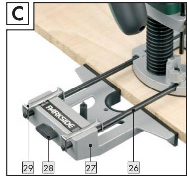
Figure C:
26 Guide rod for guide fence
[27] Guide fence
Screw for the fine adjustment of the guide fence
[29] Stirrup for the fine adjustment of the guide fence
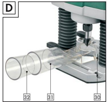
Figure D:
30 Screw for attaching the vacuum extraction adapter
31Vacuum extraction adapter
32 Reducer piece
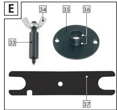
Figure E:
33 Centring pin
34 Wing nut for centring pin
35 Guide bushing
36 Guide bushing ring
[37] Spanner
- Included items
1 Carrying case
1 Router POF 1300
1 Tightening nut with integrated 6mm collet
1 Tightening nut with integrated 8mm collet
1 Router bit set (10-piece)
1 Spanner (for tightening nuts 18 + 19 (see Fig. E)
1 Guide bushing (see Fig. E)
1 Guide fence (see Fig. C)
1 Vacuum extraction adapter (incl. screws) (see Fig. D)
1 Reducer piece
1 Centring pin (see Fig. E)
1 Operating instructions
1 Booklet covering "Warranty and service"
Technical information
Rated voltage: 230V 50Hz
Nom. power input: 1300W
No-load speed: n_0 11000 - 28000 min^-1
Tool holder: 6/8mm
Plunge depth: max. 55mm
Protection class: II/回
Noise and vibration data:
Values determined in accordance with EN 60745 The sound pressure level (A-weighted) of the device is typically 95 dB (A). Uncertainty K = 3 dB. The sound level while working can exceed 106 dB (A).

Wear ear protection!
Evaluated acceleration, typical:
Hand/arm vibration a_h = 12,065 ~m / s^2
Uncertainty K = 1,744 m/s^2
WARNING: The vibration level given in these instructions has been measured in accordance with a standardised measurement procedure specified in EN 60745 and can be used to compare devices. Different uses of the device give rise to different vibration levels and in many cases they may exceed the values given in these instructions. It is easy to underestimate the vibration load if the electrical power tool is used regularly in particular circumstances.
Note: If you wish to make an accurate assessment of the vibration loads experienced during a particular period of working, you should also take into account the intervening periods of time when the device is switched off or is running but is not actually in use. This can result in a much lower vibration load over the whole of the period of working.


Safety advice
Attention! In order to protect yourself from the danger of electric shock, injury or fire when using electrical power tools, please observe the following safety precautions.
Read and observe these requirements before you use the device and keep the safety advice in a safe place. Failure to observe the instructions and advice given below may result in electric shock, fire and/or serious injury.
Workplace safety
- Keep your working area clean and clutter-free. Ensure that your working area is well lit. Untidy or poorly lit working areas can lead to accidents.
- Do not work with the device in potentially explosive environments in which there are inflammable liquids, gases or dusts. Electrical power tools create sparks, which can ignite dusts or fumes.
Use dust extraction or trapping equipment if these facilities can be fitted. If you use a vacuum dust extraction device, make sure that it is specially designed to be used for this purpose.
The correct use of these devices reduces the hazard presented by dust. There is the danger of fire when working with electrical devices that have a dust bag or can be connected to a vacuum extraction device. Under certain conditions the wood dust in the dust extraction bag (or in the vacuum's filter bag) can self-ignite, e.g. as a result of flying sparks generated when machining metals or metal objects left in wood. This can happen particularly if the wood dust is mixed with paint residue or other chemicals and the waste particles are hot from prolonged machining. Therefore you must empty the dust collection bag and filter bag before pausing or stopping work and always avoid overheating the waste particles or the vacuum's filter bag.


Keep children and other people away while you are operating the electrical power tool.
Distractions can cause you to lose control of the device.

- Electrical safety

To avoid danger to life from electric shock:
The mains plug on the device must match the mains socket. The plug must not be modified in any way. Do not use an adapter plug with devices fitted with a protective earth. Unmodified plugs and matching sockets reduce the risk of electric shock.
- Avoid touching earthed surfaces such as pipes, radiators, ovens and refrigerators with any part of your body. There is an increased risk of electric shock if your body is earthed.


Keep the device away from rain or moisture. Water entering an electrical device increases the risk of electric
- Do not use the mains lead for any purpose for which it was not intended, e.g. to carry the device or to pull the mains plug out of the mains socket. Keep the mains lead away from heat, oil, sharp edges or moving parts of the device.
Damaged or tangled mains leads or plugs increase the risk of electric shock.

A damaged tool, mains lead or plug presents a serious danger to life from electric shock.
Frequently check the condition of the device, mains lead and plug.
Check the condition of the plug and mains lead on your electrical tool regularly and have any damage repaired by a competent specialist.
- When working outdoors always use extension cables that are also approved for use outdoors. The use of an extension cable suitable for outdoor use reduces the risk of electric shock.
- Do not use an electrical power tool with damaged parts. If a dangerous situation arises pull out the mains plug from the socket immediately.
Warning! Never open up the device.
Always have any repairs carried out or replacement parts fitted at the service centre or by an electrical equipment repair specialist.
Personal safety
- Remain alert at all times and always watch what you are doing. Work carefully when using an electrical power tool. Do not use the device if you cannot concentrate or are tired or under the influence of drugs, alcohol or medication. Just one moment of carelessness when using the device can lead to serious injury.

Wear personal protective equipment and always wear safety glasses. The wearing of personal
protective equipment such as dust masks, non-slip safety shoes, protective gloves, safety helmets or ear protectors, appropriate to the type of electrical power tool used and work undertaken, reduces the risk of injury.
- Avoid unintentional operation of the device. Make sure that the switch is in the "OFF" position before you insert the mains plug into the socket. Accidents can happen if you carry the device with your finger on the ON/OFF switch or you have already switched the device on before you connect it to the mains.
Remove any setting tools or spanners before you switch the device on. A tool or spanner left attached to a rotating part of a device can lead to injury.
- Do not overestimate your own abilities. Keep proper footing and balance at all times. By doing this you will be in a better position to control the device in unforeseen circumstances.
Wear suitable clothing. Do not wear loose clothing or jewellery. Keep your hair, clothing and gloves clear of moving parts. If you have long hair, wear a hair net. Clothing, jewellery or hair that is loose or hangs from your body, head or limbs can become trapped in moving parts.
Careful handling and use of electrical power tools
- Do not overload your electrical power tool. Always use an electrical power tool that is intended for the task you are undertaking. You will work better and more safely if the tool is kept within its specified operational range.
- Do not use an electrical power tool if its switch is defective. An electrical power tool that can no longer be switched on and off is dangerous and must be repaired.
Pull the mains plug from the socket before you make any adjustments to the device, change accessories or when the device is put away. This precaution prevents you from unintentionally starting the device. - When not in use always ensure that electrical power tools are kept out of reach of children. Do not let anyone use a tool with which he or she is not familiar or who has not read the instructions and advice. Electrical power tools are dangerous when they are used by inexperienced people.
-
Look after your tools meticulously. Check that moving parts are working properly and move freely. Check regularly for broken parts or parts that are damaged to the extent they detrimentally affect the functioning of the device. Have damaged parts repaired before you use the device. Many accidents have their origins in poorly maintained electrical power tools.
-
Keep cutting tools clean and sharp. Carefully maintained cutting tools with sharp cutting edges are less likely to jam and are easier to control.
Use the electrical power tool, accessories, inserted tools etc. in accordance with these instructions and advice, and the stipulations drawn up for this particular type of device. In doing this, take into account the working conditions and the task in hand. The use of electrical power tools for purposes other than those intended can lead to dangerous situations.

Safety advice relating specifically to this device
- Securely support the workpiece. Use clamps or a vice to grip the workpiece firmly. This is much safer than holding it in your hand.
Danger of fire from flying sparks! Machining metal creates flying sparks. For this reason, always make sure that nobody is placed in any danger and that there are no inflammable materials near the working area.
Warning! Be aware that persons operating the tool or in its vicinity may be at risk of being in contact with or inhaling dusts.
Take all the necessary safety precautions in relation to dusts. Working with this tool can give rise to dusts that may be hazardous to health, inflammable or explosive.
Harmful or poisonous dusts can, for example, arise from machining paints containing lead, or from certain types of hardwoods or metals. Some dusts are classified as carcinogenic. Wear a breathing mask and use a suitable dust/chip vacuum extraction device.
Warning! Keep your working area clean. Mixtures of materials can be particularly dangerous. Light metal dust, for example, may burn or explode.
Warning! Danger of electric shock from metal dust!
Machining metal can result in electrically conductive dust being deposited inside the device. In these circumstances the inside of the motor compartment must be blown out at frequent intervals with compressed air, vacuum extraction
used and the device operated through a residual current device (RCD) with a maximum trip current of 30mA .
Ensure that there is adequate ventilation when machining surfaces containing plastic or covered with paint, varnish etc., otherwise there may be a risk to your health through the generated dust.
- Do not machine materials containing asbestos.
Asbestos is a known carcinogen.
- Avoid contact with the rotating router bit, otherwise there may be risk of injury.
- Do not machine moist materials or damp surfaces, otherwise there may be a risk of electric shock.
Never leave the device working unattended, otherwise there may be a risk of injury or accident.
- Never use the device for a purpose for which it was not intended. The use of electrical power tools for purposes other than those intended can lead to dangerous situations.
Always work with the mains lead leading away from the rear of the device.
Check before use that the router is firmly seated in position, otherwise there may be a risk of injury or accident.
If a dangerous situation arises, pull the mains plug immediately out of the mains socket.
Before you insert the mains plug into the socket, always check that the device is switched off. Accidents can happen if you carry the device with your finger on the ON/OFF switch or you have already switched the device on before you connect it to the mains.
Always switch on the device before guiding it against the workpiece, otherwise there may be a risk of injury from kick-back.
After a routing task has been completed, lift the device off the workpiece and turn the clamping lever to bring the device into its top position and then switch it off.
- Switch the device off and allow it to come to a complete standstill before you put it down, otherwise there may be a risk of injury from rotating parts.
- Never machine over metal objects, nails or screws, otherwise there may be a risk of injury or damage to the device.
Hold the device only by the insulated handle if there is the risk that you might cut through a
concealed cable or the device's mains lead. Contact with an electrical lead or cable means that the metal parts of the device may also become live and this can result in electric shock.
Always keep the device clean, dry and free of oil or grease. Dirty devices increase the risk of injury (e.g. by slipping). You will work better and more safely with clean cutting tools.
- Original accessories/ attachments
Use only the accessories and attachments detailed in the operating instructions. The use of inserted tools or accessories other than those recommended in the operating instructions could lead to you suffering an injury.
- Caution utility services!
Danger!
Ensure that you do not strike electrical cables, gas or water pipes when you are working with an electrical power tool. Check a wall using a suitable detector before you drill or cut slots.
Have you understood everything?
Once you have made yourself familiar with this general safety advice for electrical power tools, and with the help of the device's operating instructions you now know about all the functions of and how to handle your electrical power tool, you are finally in a position to start work. Observing the instructions and advice will maximise your safety while working with the device.
Preparing for use
- Router bit set/sccope of application
Router bits (also referred to as router cutters) are available in a wide range of qualities and designs to suit the type of cutting and intended application. The following descriptions give you an indicative overview (without liability) of the scope of application of different router bits. The included router bit set contains router cutters for the most common routing tasks.
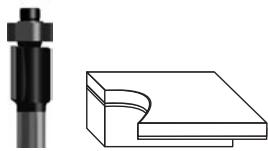
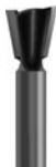
Flush trim bit with bearing:
Particularly suitable for flush trimming and chamfering laminated boards, wooden beams and edgings (plastic or veneer) in furniture making and shop fitting. The bearing allows the bit guide itself directly along the workpiece. The most common applications of this bit include rounding the edges of window frames, cupboards, tabletops, shelves and mantelpieces.
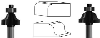
Corner rounding bit with bearing:
Corner rounding bits are suitable for profiling edges in frames and framework, especially working with solid woods, such as spruce, beech, oak and alder.
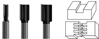
Slot cutter, with two cutting edges:
Particularly suitable for solid wood, boards, e.g. chipboard and MDF (medium density wood fibre boards) and for plastics. Suitable for milling plane
surfaces, slots for letters or butt jointed connections, notches, tongue and groove joints etc.


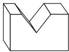
Cove cutter bit/cove cutter bit with bearing:
Cove cutter bits are used for edge profiling (e.g. concave edges), for constructing bureaux (hinged connections with concave profiles), for making decorative grooves, for texturing surfaces, for cutting juice channels etc.

V-slot cutter bit:
V-slot cutter bits are almost universal in application. They are suitable for example for making (ornamental) grooves, bevelling or engraving script etc.

Dovetail cutter bit, with two cutting edges:
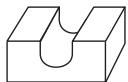
Particularly suitable for cutting strong dovetails for making furniture or boxes, e.g. for drawer runners (see Fig. G).
- Inserting a router bit
Attention! Do not press the spindle lock button before the motor has come to a standstill, otherwise there is the risk of damage.
Attention! Tighten the tightening nut with the spanner 37 only after a router bit has been inserted. Failure to observe this advice may result in damage to the collet.
1. Selecting the router bit
Select a router bit appropriate to the material and suitable for the purpose. Router bits made from high speed steel (HSS) are suitable for machining soft materials, such as plastic or softwood. Carbide-tipped router bits (HM) are suitable for machining hard materials, such as hardwood or aluminium.
Note! Use only routing tools with an allowable speed at least as high as the highest no-load speed of the device! The shank diameter of the router bit must correspond with that of the collet!
2. Inserting the router bit
Before carry out any work on the device, first pull the plug out of the mains socket. Wear protective gloves when inserting or replacing a router bit.
Fold down the chip shield 4.
Press the spindle lock button 2 and keep it depressed. Turn the spindle 3 if necessary by hand until it engages. Tighten the tightening nuts (18 or 19) by hand on to the spindle 3.
Note: All the router bits in the supplied router bit set have an 8 mm shank. Use the tightening nut with integrated 8mm collet for these and the integrated 6 mm collet for router bits with a 6 mm shank.
Now insert the router bit. At least 20mm of its shank must be inserted.
- Tighten the tightening nut (18 or 19) with the spanner 37.
Now release the spindle lock button 2
Fold up the chip shield 4.
Note: Tighten the tightening nut with the spanner 37 only after a router bit has been inserted.
- Connecting a dust/chip vacuum extraction device
Danger! Protect yourself during your work by wearing a dust mask and use a suitable dust/chip vacuum extraction device.
- Attaching the vacuum extraction adapter (with reducer piece)
Warning: Always pull the mains plug is out of the socket before doing any work on the device. This precaution is intended to prevent you from unintentionally starting the device.
Note: Remove the router bit before you attach the vacuum extraction adapter [31].
Place the vacuum extraction adapter 31 on to the base plate 5. Fasten the vacuum extraction adapter 31 to the base plate 5 using the two screws 30. Screw the two screws 30 in from below. If it is necessary to use the reducer piece 32, it can be pushed into the vacuum extraction adapter 31.
Connect a vacuum extraction device suitable for extracting dust and chips by means of a suction hose to the vacuum extraction adapter 31 or to the reducer piece 32.
Operation
Connect the device by its mains plug to a power source supplying 220V - 230V 50Hz
- Switching on/off
Switching on
To switch off the device first press the safety lock-out [24] and keep it depressed. Then press the ON/OFF switch [23].
Switching off
To switch off the device, release the ON/OFF switch 23 again.
Illuminating the routing area
The integrated illumination for the routing area lights up and can be switched off again by pressing the On/Off switch [23].
Preselecting the rotation speed
Set the required rotational speed using the thumbwheel for speed preselection 25.
1-2 = low rotational speed
3-4 = medium rotational speed
5-6 = high rotational speed
□ If possible always determine the optimum setting beforehand using a practical test.
If you have been working for a long period using a low rotational speed, you should cool the device by running it at the highest speed for about 1 minute under no-load conditions.
Table of indicative rotational speeds (for guidance only)
| Material | Router bit | Speed setting |
| Aluminium | 4-15 mm | 1-2 |
| 16-40 mm | 1 | |
| Plastic | 4-15 mm | 2-3 |
| 16-40 mm | 1-2 | |
| Chipboard | 4-10 mm | 3-6 |
| 12-20 mm | 2-4 | |
| 22-40 mm | 1-3 | |
| Softwood e.g.: spruce, pine, fir | 4-10 mm | 5-6 |
| 12-20 mm | 3-6 | |
| 22-40 mm | 1-3 | |
| Hardwood e.g.: maple, birch, oak, cherry | 4-10 mm | 5-6 |
| 12-20 mm | 3-4 | |
| 22-40 mm | 1-2 |
The indicative values in the table are for guidance only. The required rotational speed depends on the material and the working conditions and should be determined by means of a practical test.
- Setting the depth of cut
Danger! Set the cutting depth only after the device has been switched off!
Coarse setting of the depth of cut
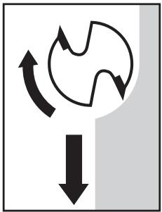
- Ensure that the clamping lever [15] is applied. If it is released turn it anticlockwise until it is applied.
- Place the device on the workpiece.
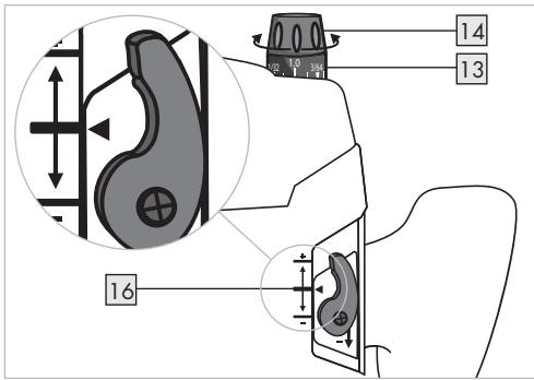
- Turn the fine adjustment knob 14 for depth of cut until the markings for zero-reset 16 on the back of the device are in alignment.
- Turn the scale for fine adjustment of depth of cut in mm 13 until the "0" point aligns with the marking on the housing.
- Turn the step buffer 7 until it engages in the lowest position.
- Release the stop screw 9 for depth stop.
- Release the clamping lever 15 by turning it clockwise and press the device downwards until the router bit comes into contact with the workpiece surface.
- Apply the clamping lever 15 by turning it anticlockwise.
- Push the depth stop 10 downwards until it is sitting at the lowest position of the step buffer 7 . Press the slider with index mark 11 to position "0" of the scale for coarse adjustment of depth of cut in mm 12 .
- Set the depth stop to the desired routing depth and tighten the stop screw for depth stop. After this, the setting of the slider with index mark should not be changed.
- Release the clamping lever [15] and then guide the device back up again.
After setting the depth of cut do not change the setting of the slider with index mark 11 on the depth stop 10. The current depth of cut setting can now be read on the scale for coarse adjustment of depth of cut in mm 12.
Example: Create a guide slot in a pine drawer:
width: 16mm , depth: 10mm
- Select the 16mm slot cutter from the router bit set and insert it as described in the section about "Inserting a router bit".
Preselect a medium rotational speed (approx. 3-4). - Carry out steps 1 to 9 as described in the section above.
Set the required depth of cut by setting the depth stop to "10" on the scale for coarse adjustment of depth of cut in mm [12]. Now tighten the stop screw for depth stop [9]. - Secure the workpiece and carry out the routing process as described in the following sections.
Fine setting the depth of cut
The depth of cut can be adjusted using the fine adjustment knob 14 for depth of cut. (1 division = 0.1mm / 1 revolution = 1.5mm max. +-8 mm movement.
Example: Take the device back up and measure the machined slot depth (required machined depth = 10mm /actual = 9.8mm )
Place the device in a position which allows the router bit to be lowered without obstruction.
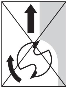
- Release the clamping lever [15] by turning it clockwise and press the device carefully downwards until the depth stop [10] sits on the step buffer [7].
□ Apply the clamping lever [15] by turning it anticlockwise.
Turn the scale for fine adjustment of depth of cut in mm 13 to "0". Release the stop screw 9 for depth stop 10.
Use the fine adjustment knob 14 to change the depth of cut by 0.2mm / 2 divisions (=) difference between required and actual), turn clockwise, in the direction of the ^+ arrow.
- Tighten the stop screw 9 for depth stop 10 again.
- Release the clamping lever by turning it clockwise and then guide the device back up again. Check the depth of cut by carrying out a further practical test.
Setting the depth of cut using the step buffer
You can use the step buffer 7 to make greater depths of cut in several successive stages in which less material is removed.
Set the required depth of cut with the lowest step of the step buffer (as described above).
□ Afterwards the higher steps can be used for the first few cuts.
- Direction of feed
Danger! When machining with the direction of rotation the router can be ripped out of your hands. This may cause injury.
Always machine against the direction of rotation of the router bit!
- Routing process
Adjust the depth of cut as described above.
Place the device on the workpiece and switch it on.
- Release the clamping lever [15] by turning it clockwise and press the device downwards until the depth stop [10] runs against the workpiece.
Lock the device by turning the clamping lever 15 anticlockwise.
- Carry out the routing process using uniform speed and pressure
- Stop the routing process by lifting the device from the workpiece and switching it off.
- Setting the guide bushing
Insert the guide bushing 35 from below into the guide plate 6.
- Fasten the guide bushing 35 to the base plate 5 using the two screws 30 of the vacuum extraction adapter. Make sure that the guide bushing 35 is the right way round - the guide bushing ring 36 must be facing downwards.
- Routing with the guide bushing
Note! When using the guide bushing, the template must have a minimum thickness of 8mm .
Note! The template must be at least as thick as the guide bushing ring 36 of guide bushing 35.
Note! Choose a router bit with a smaller diameter than the internal diameter of the guide bushing.
By using the guide bushing 35 you can superimpose templates or patterns on to the workpiece.
Place the device with the guide bushing against the template.
- Release the clamping lever by turning it clockwise and lower the device until the previously set depth of cut is reached.
Now guide the device with the projecting guide bushing along the template, whilst applying light pressure.
- Routing with the guide fence
Insert the guide fence 27 into the guide rails 22 of the base plate 5 and fasten it into place to suit the required dimension using the locking screw 21.
Place the guide fence 27 against the edge of the workpiece. Now carry out the fine adjustment. Turning the screw for the fine adjustment 28 of the guide fence clockwise reduces the distance. Turning the screw for the fine adjustment 28 of the guide fence anticlockwise increases the distance. The stirrup 29 for the fine adjustment of the guide fence indicates the corrections on the scale.
After the device has been lowered, apply the clamping lever 15 by turning it anticlockwise.
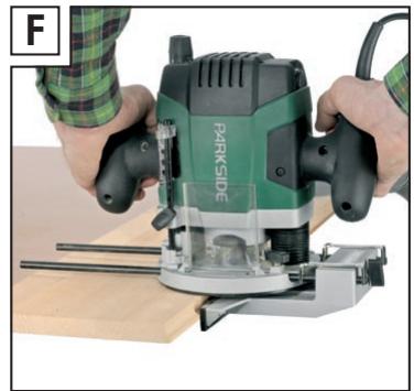
- Carry out the routing process using uniform speed and pressure (see Figs. F, G).
After the routing process lift the device from the workpiece and switch it off.
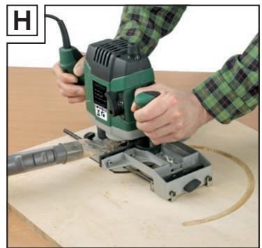
- Routing a circular arc profile/ Fig. H
- Reverse the guide fence [27] (stop edge faces upwards) and push it into the guide rails [22] of the base plate [5]. Fasten it in place with the locking screws [21].
Now screw the centring pin 33 with the wing nut 34 for centring pin through the outer hole of the guide fence 27. Use the small recess at the side of the spanner 37 to provide counter pressure. - Insert the centring pin 33 into the marked centre of the circle. Now carry out the fine adjustment. Turning the screw for the fine adjustment of the guide fence 28 clockwise reduces the radius. Turning the screw for the fine adjustment of the guide fence 28 anticlockwise increases the radius. Notice that the stirrup 29 for the fine adjustment of the guide fence moves with reference to the scale of the guide fence 27 during this process.
Now guide the device with even speed and pressure over the workpiece surface. Notice that the path of guide fence [27] is controlled by the setting on the stirrup [29] for the fine adjustment of the guide fence.
Note: You can make changes to the radius of the circle to be machined by changing the position of the guide fence [27].
- Maintenance and cleaning
- Maintenance
The device requires no maintenance.
Have repairs carried out only by an electrical power tool specialist or your service centre.
- Cleaning
Warning! Pull the mains lead out of the mains socket before you clean the device, otherwise there may be risk of injury.
Always keep the device and the ventilation slots clean, dry and free of oil or grease. Dirty devices increase the risk of injury (e.g. by slipping). You will work better and more safely with clean cutting tools.
Do not allow any liquids to enter the inside of the device, otherwise there may be a risk of electric shock. Use a dry cloth to clean the housing.
Never use petrol, solvents or cleaning agents that might attack plastic.
Disposal

The packaging is wholly composed of environmentally-friendly materials that can be disposed of at a local recycling centre.

Do not dispose of electrical power tools with the household rubbish!
In accordance with European Directive 2002/96/EC (covering waste electrical and electronic equipment) and its transposition into national legislation, worn out electrical power tools must be collected separately and taken for environmentally compatible recycling.
Contact your local refuse disposal authority for more details of how to dispose of your worn out electrical devices.
Information
Service centre
The service centre for your country is shown in the warranty documentation.
Have your device repaired only by qualified specialist personnel using original manufacturer parts only. This will ensure that your device remains safe to use.
If the plug or mains lead needs to be replaced, always have the replacement carried out by the manufacturer or its service centre. This will ensure that your device remains safe to use.
Declaration of Conformity/ Manufacturer CE
We, Kompernaß GmbH, Burgstr. 21, D-44867 Bochum, Germany, declare that this product complies with the following EU directives:
Machinery Directive (98/37/EC)
EU Low Voltage Directive (2006/95/EC)
Electromagnetic Compatibility (2004/108/EC)
Type/device description:
Parkside RouterPOF1300
Bochum, 31.10.2007

Hans Kompernaβ
- Managing Director -
We reserve the right to make technical modifications in the course of further development.