
CR-N400 - Surveillance Camera CANON - Free user manual and instructions
Find the device manual for free CR-N400 CANON in PDF.
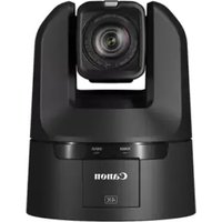


| Product Type | Pan-Tilt-Zoom (PTZ) Surveillance Camera |
| Resolution | 4K UHD (3840 x 2160) at 30 fps |
| Image Sensor | 1/2.3-inch CMOS |
| Lens | Built-in, 4.3 to 129 mm (30x optical zoom) |
| Zoom | 30x optical, 10x digital |
| Video Compression | H.265, H.264, MJPEG |
| Network Interface | RJ45 10/100/1000 Mbps Ethernet |
| Power Source | PoE+ (IEEE 802.3at) or 24V AC/DC |
| Dimensions (W x H x D) | 178 x 178 x 180 mm |
| Weight | Approx 2.3 kg |
| Operating Temperature | -10°C to 50°C (14°F to 122°F) |
| Main Functions | PTZ control, auto tracking, preset positions, privacy masking, motion detection |
| Maintenance | Clean lens with soft cloth; firmware updates via web interface |
| Safety Features | Overvoltage protection, IP66 weatherproof rating |
| Spare Parts Available | Lens assembly, mainboard, power supply, mounting bracket |
| Repairability | Modular design; replaceable components by authorized service |
| General Information | Compatible with ONVIF Profile S/T, supports NVR & cloud, indoor/outdoor use |
Frequently Asked Questions - CR-N400 CANON
User questions about CR-N400 CANON
0 question about this device. Answer the ones you know or ask your own.
Ask a new question about this device
Download the instructions for your Surveillance Camera in PDF format for free! Find your manual CR-N400 - CANON and take your electronic device back in hand. On this page are published all the documents necessary for the use of your device. CR-N400 by CANON.
USER MANUAL CR-N400 CANON
Failure to follow the instructions may result in death or serious injury.
Do not install in the following places:
- Places in direct sunlight, near heat-generating objects, or locations subject to high temperatures.
- Places near fire sources or flammable solvents (alcohol, thinner, fuel, etc.).
- Humid or dusty places.
- Places subject to oily smoke or steam.
- Confined or enclosed places.
Failure to do so may result in fire or electric shock.
Notes on installation at high places
- For installation or inspection of this camera, consult the dealer where you purchased the product.
- Install the camera in a way that ensures sufficient holding strength according to the mounting place such as the wall, ceiling, etc. Also, make sure that the mounting place can sufficiently support the total weight including the mounting parts and reinforce it if necessary.
- Prepare fixing screws suitable for the location and type of surface the camera is to be installed.
- Periodically check the mounting brackets and screws for rust and loosening.
- Do not install in unstable places, places subject to significant vibration or impact, or places subject to salt damage or corrosive gas.
- Be sure to attach the safety wire when installing the camera.
- Use the included ceiling plate to install the camera. Do not install it with only the tripod screws.
Failure to do so may result in the camera falling or other accidents.
General notes on the camera
- If any defective conditions such as smoke, strange sounds, heat, strange odors, damage or cracks on the external case are discovered, immediately stop using the camera, remove it from the power supply (or the LAN cable for PoE++ power supply), and contact your nearest dealer. Place the compact power adapter near the power outlet and avoid placing objects around the power plug so that the power can be turned off immediately in the event of an emergency.
- Do not touch the camera or the connecting cables during a thunderstorm.
- Do not disassemble or modify the camera.
- Do not scratch, pull, or forcefully bend the cables, or put a load on their connections.
- Do not spray the camera with water, or otherwise make it wet.
- Do not touch the camera, the compact power adapter, cable connectors, power plugs, or power outlets with wet hands.
- Do not allow water, metal or other foreign objects to enter the camera.
- Do not use flammable sprays near the camera.
- Do not leave compact power adapter (or the LAN cable for PoE++ power supply) connected when the camera is not in use for long periods.
- Do not use flammable solvents such as alcohol, paint thinner or benzine when cleaning the camera.
- Do not block the air intake or air exit vents.
Failure to do so may result in fire or electric shock.
Notes on the power supply
- Use only the included compact power adapter when using an AC adapter.
- The included compact power adapter and power cable are for this product only. They cannot be used for other devices.
- Do not place heavy objects on the power cable (or the LAN cable for PoE++ power supply) or pull, forcibly bend, scratch or modify it.
- Do not allow metal pins or debris to touch the power plug or terminals.
- Wipe any dust off of the power plug. Also, if the connection is made to the power outlet in a dusty area, take measures to prevent tracking.
- Make sure the power plug (or the LAN cable for PoE++ power supply) is seated all the way, and do not use it when the insertion is insufficient.
- Do not use a damaged power plug or a loose power outlet, or use it in a manner that exceeds the rating of the wiring device such as connecting multiple plugs to an outlet.
Failure to do so may result in fire or electric shock.
Notes on batteries
- Do not put batteries in the fire, or do not heat, short circuit or disassemble them.
- Do not charge the included batteries.
- Do not use batteries other than those specified.
Failure to do so may result in fire or electric shock.
Do not use the product at:
- Places where the use is prohibited, such as in hospitals and on airplanes.
- Places within reach of babies and toddlers.
Use at such places can cause equipment to malfunction due to radio waves and lead to accidents, or cause electric shock and injuries.

Caution
Failure to follow the instructions may result in injuries or property damages.
Notes on installation
- Installation must be carried out safely and securely in accordance with the relevant regulations for technical standards of electrical installation.
Failure to do so may result in accidents.
Notes on installation
• Take care not to damage wiring or piping.
Failure to do so may result in damage to surrounding items.
General notes on the camera
- Do not touch the edges of metal parts with bare hands.
- Be careful not to get your fingers caught when installing.
Failure to do so may result in injuries.
Notes on batteries
- Remove the batteries when they have been used up or will not be used for a long time.
- When replacing the batteries, replace both batteries at the same time. Also, do not use different types of batteries together.
- Make sure + and - of the battery are oriented correctly.
- If any liquid from inside the battery gets on your body due to leakage, rinse it off thoroughly with water.
Failure to do so may result in injuries and malfunctions.
Notes on settings
- When using a microphone, set [Audio Input Mode] correctly according to the specifications of the microphone.
Failure to do so may damage the camera or microphone.

Important
- Do not install the camera in places where radiation, X-rays, strong radio waves or strong magnetism are generated. It may cause video and audio disturbance, noise, or malfunctions.
- We recommend the installation of a lightning arrester (a surge protection device) as a measure against failures caused by lightning strikes.
• Take measures to remove static electricity before performing any procedures. - Do not connect power supply cables to the BNC jacks as it may result in damage.
- Do not connect the PoE cable to the RS-422 terminal.
- Do not connect the compact power adapter to a transformer.
- If grounding is performed, make sure to ground the camera and any external devices individually before connecting them with a cable. Failure to do so may damage electrical components.
- If there is condensation, please wait to power on, until the condensation dissipates.
- Do not hold the device by the camera head.
- Do not turn the camera rotator by hand.
• After turning off the power, do not turn the power on again for at least five seconds. - Do not point the camera at strong light sources (such as the sun on a clear day or strong artificial light sources). Internal components such as the image sensor could be damaged.
- Do not carry the camera on a tripod.
Notes for When and After Installing the Camera
When Installing the Camera
Installation at high places

Caution
Request a professional installer for all installation work. Never try to install the camera yourself.
Doing so may result in unforeseen accidents such as dropping the camera or electric shock.
Introduction
Thank you for purchasing a Canon Remote Camera (hereafter referred to as the camera)*.
This camera is for indoor use only.
This document (User Manual) explains the camera's installation, settings and operations. Read this guide carefully before using the camera to ensure correct use. Also, be sure to read the 'Safety Precautions' in this document and the "Important Information" included with the camera.
* The cameras described in this document may include models not available in your country and/or region.
For the latest information on this product (firmware and software, user manuals, operating environment, etc.), please refer to the Canon website.
Trademarks
- Microsoft, Windows and Microsoft Edge are trademarks or registered trademarks of Microsoft Corporation in the United States and other countries.
- Windows is legally recognized as the Microsoft Windows Operating System.
• macOS is a trademark of Apple Inc., registered in the U.S. and other countries. - Safari is a trademark of Apple Inc.
- IOS is a trademark or registered trademark of Cisco in the U.S. and other countries and is used under license.
- The terms HDMI, HDMI High-Definition Multimedia Interface, HDMI Trade dress and the HDMI Logos are trademarks or registered trademarks of HDMI Licensing Administrator, Inc.
- Wi-Fi is a registered trademark of the Wi-Fi Alliance.
- NDI is a trademark or registered trademark of Vizrt NDI AB in the United States and other countries.
- All other company or product names used in this document are trademarks or registered trademarks of their respective holders.

Software License Agreement
For the software license agreement, refer to the text file provided with the software and installer.
Except as expressly permitted by the law in effect in the jurisdiction in which you are located, you shall not reverse engineer the firmware which is contained in this product ("Firmware") and you shall not modify the Firmware. TO THE FULL EXTENT PERMITTED BY APPLICABLE LAW, IN NO EVENT SHALL EITHER CANON, OR CANON'S LICENSORS BE LIABLE FOR ANY DAMAGES WHATSOEVER ARISING OUT OF USING THE FIRMWARE. The Firmware may contain third party software components. Notwithstanding anything contained herein to the contrary, the terms and conditions of such third party software components shall be applied to your usage of the Firmware.
Third Party Software
This camera contains third party software modules. Confirm each module's license conditions in [System] > [Maintenance] > [General] > [Tool] > [See Third Party Software License Conditions] on the Settings Page. The Auto Tracking Application also contains third party software modules. For each module's license conditions, refer to "Third Party Software" on the Auto Tracking Application User Manual.
This product partly contains software of which the source code is provided in accordance with the license.
(1) Please access https://global.canon/en/oss/scd/index.html to fill the request form so that you receive an e-mail with the URL to download the source code; or
(2) Please send us a letter in writing with the following information, so that you receive the source code via postal mail. In case you have chosen this (2), WE MAY CHARGE YOU no more than the cost of performing this distribution.
(i) Your Address (Country/Region, ZIP code, Address, Your name) [mandatory]
(ii) Your e-mail address (for the purpose of possible communication with us) [optional]
(iii) Product Name/Application Name [mandatory]
(iv) Product/Application Software Version [optional]
(i) Your Address (Country/Region, ZIP code, Address, Your name) [mandatory] (ii) Your e-mail address (for the purpose of possible communication with us) [optional] (iii) Product Name/Application Name [mandatory] (iv) Product/Application Software Version [optional]
If you do not specify a version, we will send source code corresponding to the latest version.
- Address:
Open Source Promotion Division, Canon Inc.
30-2, Shimomaruko 3-chome, Ohta-ku, Tokyo 146-8501, Japan
- Please see Privacy Notice at Canon Global https://global.canon/en/oss/scd/privacy-notice.html
This product is licensed under AT&T patents for the MPEG-4 standard and may be used for encoding MPEG-4 compliant video and/or decoding MPEG-4 compliant video that was encoded only (1) for a personal and non-commercial purpose or (2) by a video provider licensed under the AT&T patents to provide MPEG-4 compliant video. No license is granted or implied for any other use for MPEG-4 standard.
THIS PRODUCT IS LICENSED UNDER THE AVC PATENT PORTFOLIO LICENSE FOR THE PERSONAL USE OF A CONSUMER OR OTHER USES IN WHICH IT DOES NOT RECEIVE REMUNERATION TO (i) ENCODE VIDEO IN COMPLIANCE WITH THE AVC STANDARD ("AVC VIDEO") AND/OR (ii) DECODE AVC VIDEO THAT WAS ENCODED BY A CONSUMER ENGAGED IN A PERSONAL ACTIVITY AND/OR WAS OBTAINED FROM A VIDEO PROVIDER LICENSED TO PROVIDE AVC VIDEO. NO LICENSE IS GRANTED OR SHALL BE IMPLIED FOR ANY OTHER USE. ADDITIONAL INFORMATION MAY BE OBTAINED FROM MPEG LA, L.L.C. SEE
HTTP://WWW.MPEGLA.COM
This product comes with exFAT, a licensed file system technology from Microsoft.
Only for European Union and EEA (Norway, Iceland and Liechtenstein) and United Kingdom

These symbols indicate that this product is not to be disposed of with your household waste, according to the WEEE Directive (2012/19/EU), the Battery Regulation ((EU) 2023/1542) and/or national legislation implementing those Directive and Regulation and the UK Waste Electrical and Electronic Equipment Regulations and the UK Batteries and Accumulators Regulations. If a chemical symbol is printed beneath the symbol shown above, in accordance with the Battery Regulation and the UK Batteries and Accumulators Regulations, this indicates that a heavy metal
(Hg = Mercury, Cd = Cadmium, Pb = Lead) is present in this battery or accumulator at a concentration above an applicable threshold specified in the Battery Regulation and the UK Batteries and Accumulators Regulations.
This product should be handed over to a designated collection point, e.g., on an authorized one-for-one basis when you buy a new similar product or to an authorized collection site for recycling waste electrical and electronic equipment (EEE) and batteries and accumulators. Improper handling of this type of waste could have a possible impact on the environment and human health due to potentially hazardous substances that are generally associated with EEE. Your cooperation in the correct disposal of this product will contribute to the effective usage of natural resources.
For more information about the recycling of this product, please contact your local city office, waste authority, approved scheme or your household waste disposal service or visit www.canon-europe.com/sustainability/approach/.
Compliance with Applicable Laws/intellectual Property Rights: Please note that your use of this product may subject you to certain laws, rules and regulations, including but not limited to, privacy, wiretapping and intellectual property and publicity laws. Please be sure your use of this product and/or any resulting recordings or footage complies with applicable laws, rules and regulations.
Canon Inc. and its affiliates shall have absolutely no liability with respect to any claims made by third parties that your use of this product does not comply with applicable laws, rules and regulations and any resulting claims brought against you by third parties alleging non-compliance with such laws, or otherwise violates any third party's intellectual property, personal, privacy or proprietary rights as a result of your use of the product. We are also not responsible to you for any liability whatsoever resulting from your use, and/or installation of this product, and/or any loss of any recordings or footage.
Limited Warranty: Please check the in-box materials for more information about the limited warranty that pertains to your product.
Installation: This product should NOT be installed outdoors. You are solely responsible for the proper installation of this product. To the extent permitted by law, Canon Inc. and its affiliates shall have absolutely no liability to you with respect to any damages or liabilities associated with the improper use of, or the installation of this product, or for any personal injuries sustained by you or any third parties as a result of any such improper use or installation of this product, whether or not the installation of this product was by you, or by any third party.
Network Security: You are responsible for the network security of this product and its use. To the extent permitted by law, neither Canon Inc., nor any of its affiliates shall be liable to you for any losses, direct, indirect incidental or consequential damages or liabilities arising from any security breaches of this product and/or for any resulting claims brought against you by third parties as a result of such security breaches due to network security of this product. You need to take appropriate steps to help avoid security breaches which, depending on a variety of factors, including your network environment, can include, but may not be limited to, the following:
- Use the product in a network secured by a firewall, or other security protocol
- Set passwords at least 8 characters in length, including at least 3 different types of characters, such as upper case, lower case and symbols and numbers
- Change passwords frequently; avoid sharing passwords
- Change the HTTP port number of the product
- Limit access to the product by other network devices
- Restrict those who log in to the network to those who have authorized user name and password
• After accessing the product as an administrator, be sure to close all web browsers - Use security software – install appropriate software to protect against intrusions and infections that can compromise the security of the product and its use
- If the product is connected to a network that includes personal computers, make sure that the system is not infected with computer viruses or other malicious programs (using a regularly updated antivirus program, antispyware program, etc.)
- Avoid connections that use public lines
- Do not install the product in locations where the unit, cables and other equipment can be easily accessed, damaged or destroyed by persons with malicious intent
- Security risks and guidelines are always evolving; the above list is intended to include potential steps that can be taken to help avoid security breaches and is not all inclusive. Please consult with an information security specialist for further information.
Privacy:
- Do not install this product in areas where people have a reasonable expectation of privacy, including but not limited to, bedrooms, dressing rooms, locker rooms and rest room facilities.
- Some jurisdictions require signage disclosing the existence of camera equipment. Please check your own area's laws for requirements.
- Making audio recordings is heavily regulated and can vary significantly by area. Please check laws in your jurisdiction before making any audio recordings.
User Manuals
Types of User Manuals
The following describes the different camera user manuals.
"Important Information" (Included)
This describes safety precautions, procedures for installing the camera, and downloading information from the Canon website.
"User Manual" (This Manual)
This explains the camera's installation, initial settings, other settings on the Settings Page, troubleshooting, and major specifications, etc.
How to Use This Document
The assumed reading format of this document is on a computer screen.
Notes
- Any unauthorized reproduction of this document is prohibited.
- The contents of this document are subject to change without any prior notice.
3 This document has been prepared with the utmost attention to accuracy. If you have any comments, however, please contact a Canon sales representative. - Canon shall assume no liability for any outcome of using this product, notwithstanding items 2 and 3 above.
Software Screenshots
The software screenshots samples shown in this document are for illustration only. The screenshots may differ from the actual screens displayed.
Descriptions use sample screens when connected to the CR-N400, with Windows 11 for the operating system and Microsoft Edge for the web browser.
Symbols Used in This Document
| Symbol Meaning | |
| Important | Cautions and restrictions during operation. Make sure to read these carefully. |
| Note | Supplementary descriptions and reference information. |
Names of Parts

(1) Camera head
(2) Base
(3) Air intake vent
(4) Tally lamp (P. 132)
(5) Lens
(6) IR remote controller receiver
(7) STATUS lamp (P. 132)
(8) POWER lamp (P. 132)

(9) Logo plate
(10) Rubber feet
(11) Rating label
(12) Screw hole for tripod
(13) Screw hole for fixing ceiling plate
(14) Air exit vent
(15) Rear panel (CR-N400 illustration)
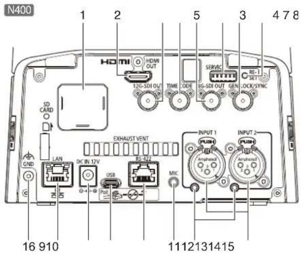
(1) SD card slot N400 For future expansion.
(2) HDMI OUT Terminal Terminal for HDMI output.
(3) 12G-SDI OUT Terminal N400 Terminal for 12G-SDI output (BNC).
(4) TIME CODE Terminal N400 Terminal for time code input/output (BNC).
(5) 3G-SDI OUT Terminal Terminal for 3G-SDI output (BNC).
(6) SERVICE Switch Set various functions (P. 21).
(7) GEN-LOCK/SYNC Terminal N400 Terminal for the synchronization signal input/output (BNC) to synchronize the videos from the camera and external devices. If the reference signal is unstable, external synchronization is not possible. Subcarriers do not synchronize.
(8) RESET Switch Initialize the camera settings to the factory defaults (P. 146).
(9) INPUT1/INPUT2 Terminal N400 XLR terminals for audio input. It can be used for microphone/line input. • Microphone power (Phantom power): 48 V DC
(10) LED for phantom power supply N400 It is lit in blue when the phantom power is supplied.
(11) MIC Terminal Stereo ∅3.5 mm (0.14 in.) terminal for audio input. It can be used for microphone/line input. • Microphone power: 2.4 V DC
(12) RS-422 Terminal Serial terminal (RJ-45 connector) for RS-422. Connect the GNDs on both ends to stabilize the voltage level of the signal.

Use category 5e or higher STP cables.
| Pin number | Function | |
| 1 | TX- | Output (-) |
| 2 | TX+ | Output (+) |
| 3 | RX- | Input (-) |
| 4 | GND | - |
| 5 | GND | - |
| 6 | RX+ | Input (+) |
| 7 | NC | - |
| 8 | NC | - |
(13) USB Terminal (Type-C) Terminal for UVC (USB Video Class). In order to use as a USB camera, the Service switch needs to be set (P. 21).
(14) DC IN 12V Terminal Power supply terminal for the compact power adapter.
(15) LAN Terminal This terminal is for a network connection (RJ-45 connector). The built-in PoE++ (Power over Ethernet++) function allows the camera to be powered by a PoE++ HUB that complies with IEEE802.3bt Type 3 or higher via a LAN cable. Use a category 5e or higher STP (shielded type) LAN cable, up to 100 m (328 ft.) in length.
(16) GND Terminal Ground terminal of the camera.

Important
- Some PoE++ HUBs can limit the power for each port, but applying limits may interfere with performance. In this case, do not limit the power.
- Some PoE++ HUBs have limits for the total power consumption for the ports, which can interfere with performance when multiple ports are in use. For more information, check the instruction guide for the corresponding PoE++ HUB.

Note
- The camera is not equipped with a power switch. To turn the camera on and off, insert and remove the cable of the compact power adapter connected to the "14. DC IN 12V terminal" or the PoE++ HUB connected to the "15. LAN terminal", which supplies power.
- When both the PoE++ HUB and the compact power adapter are connected, supply from the compact power adapter takes priority. However, note that if you disconnect the compact power adapter while both are connected, the power will switch to PoE++ (LAN cable), and the camera will restart.
- The audio input terminals ("9. INPUT1/INPUT2 terminal", "11. MIC terminal") and microphones should be set using the Settings Page (P. 86).
Table of Contents
Safety Precautions.... 2
Notes for When and After Installing the Camera.... 4
Introduction.... 5
Trademarks 5
Software License Agreement....5
Third Party Software....6
User Manuals....8
Types of User Manuals 8
How to Use This Document 8
Names of Parts 9
Chapter 1 Installation and connection
Examples of System Configuration.... 18
Before using the camera 21
Initial settings 21
SERVICE Switch Settings....21
Installation.... 22
Dimensions 23
Installing the Camera 24
Chapter 2 Before Use
Security Checking/Settings 30
Checking the Firewall Settings (Windows)....30
Initial Camera Settings.... 31
Settings using the Camera Search Tool 31
Camera's Settings Page from the Web Browser 33
Chapter 3 Camera Setup
Overview 35
Accessing from a Web Browser 35
Configuration of the Settings Page 37
Camera Operation 40
Operation by Clicking on the Video Display Area or by Slider 40
Exposure Settings.... 42
WB Settings 47
Focus Settings 49
Autofocus....49
Manual Focus....51
Clicking on the Screen....53
Custom Picture Settings 54
PTZ/IS Settings 61
Preset Settings....62
Registering Presets....62
Calling Presets and Speed Specification 63
Deleting Presets....64
Other Functions 65
Crop Settings 66
Monitoring Settings....67
OSD Settings 73
Assistance Settings....76
System Settings 78
Screen Configuration 78
Setting Items 79
Common Operations....79
[System] > [Video and Audio] > [HDMI/SDI] 81
HDMI/SDI Shared 81
Crop 82
SDI 82
[System] > [Video and Audio] > [IP Streaming Video]....83
Mainstream 83
Substream 1....84
Substream 2....84
Crop 84
[System] > [Video and Audio] > [Audio]....86
General Audio 86
IP Audio Streaming 87
[System] > [Video and Audio] > [Movement Range].... 88
Pan/Tilt 88
Zoom 88
[System] > [Server] > [HTTP/Video]....89
HTTP Server 89
Video Server 89
[System] > [Server] > [RTP] 90
RTP Server 90
Audio Settings....90
RTP Mainstream, RTP Substream 1, RTP Substream 2....91
[System] > [Communication] > [Network]....92
LAN 92
IPv4 92
IPv6 93
DNS....93
mDNS 94
Update Firmware 94
[System] > [Communication] > [Wireless LAN] 95
Interface 95
Access Point 95
IPv4 96
[System] > [Communication] > [External Connection (IP)]. 97
Standard Communication (IP)....97
NDI||HX 97
RTMP 98
Output Tracking Data....99
SRT....99
[System] > [Communication] > [External Connection (Serial)] 101
Serial Port....101
Standard Communication (Serial).... 102
[System] > [Security] > [Certificate Management] 103
Server Certificate Management 103
Create Certificate 103
CA Certificate Management.... 104
CRL Management 104
[System] > [Security] > [SSL/TLS] 105
Encrypted Communications.... 105
Server Certificate 105
[System] > [Security] > [User Management] 106
Administrator Account 107
Authorized User Account....107
User Authority 107
[System] > [Security] > [Host Access Restrictions].... 108
IPv4 Host Access Restrictions 108
IPv6 Host Access Restrictions 108
[System] > [System] > [Camera] 109
Camera Name 109
Installation Conditions.... 109
Camera Control....110
Color Bars 110
Tally Lamp....110
IR Remote Controller....110
Genlock 111
Time Code 111
[System] > [System] > [Add-On] 113
Add-On Management 113
Information About the Selected Application 114
Auto Tracking Application (Lite) 114
[System] > [System] > [Date and Time].... 115
Current Date and Time.... 115
Settings 115
[System] > [System] > [Environment] 117
Environment 117
[USB Camera].... 117
[System] > [Maintenance] > [General] 118
Device Information.... 118
Tool 118
Initialization 118
[System] > [Maintenance] > [Backup/Restore] 120
Backup....120
Restore....120
[System] > [Maintenance] > [Update Firmware] 122
Device Information.... 122
Online Update....122
Offline Update....122
[System] > [Maintenance] > [Log] 124
View Logs....124
Chapter 4 IR Remote Controller
Names and Functions of Parts 126
Handling the Remote Controller 128
Chapter 5 Appendix
USB Camera Function 130
Image Adjustment/Camera Control Functions.... 130
Troubleshooting....131
List of Log Messages 134
Log Messages on the Camera.... 134
Error Log 134
Warning log.... 137
Notification log 141
Restoring to the Factory Default Settings 146
Restoring to the Initial Settings from a Web Browser.... 146
Restoring to the Factory Default Settings with the RESET Switch on the Camera.... 146
List of Factory Default Settings.... 148
Routine Maintenance.... 154
Cleaning the External Surface 154
Cleaning the Lens....154
Specifications 155
CR-N400/CR-N350 Main Unit 155
Accessories 158
Operating Environment.... 159
Security Measures 160
Basic Measure 1: Setting Administrator Name and Password 161
Basic Measure 2: Using the Latest Firmware .... 161
Basic Measure 3: Setting Date and Time .... 161
Basic Measure 4: Monitoring the Log 161
Measures Suitable to the Users' Environment 1: User Management 162
Measures Suitable to the Users' Environment 2: Host Access Restrictions 162
Measures Suitable to the Users' Environment 3: Setting to the Digest Authentication..... 162
Measures Suitable to the Users' Environment 4: Changing the Port Number .... 163
Measures Suitable to the Users' Environment 5: Encrypting Communication.... 163
Measures Suitable to the Users' Environment 6: Disabling Unused Functions.... 163
Precautions When Disposing the Camera.... 164
Encrypting Backup Information 164
Index 165
Chapter 1
Installation and connection
This chapter explains the procedures for installing and connecting the camera.
Examples of System Configuration
System Layout
This camera can be used by connecting with the following devices.
![graph TD A["Computer"] -->|Settings Page\nRemote Camera Control Application, etc.| B["PoE++ Hub"] C["XC Protocol-Supported Controller (RC-IP1000/RC-IP100)"] -->|Settings Page\nRemote Camera Control Application, etc.| A D["Standard Communication (IP) Supported Controller"] -->|Settings Page\nRemote C…](/content/2026/07/1492718/images/1f9d8471fa48d89ad9d53896d90c06adf7e7f8832023a5e704900da086b097ce.jpg)

Note
For details on the IR remote controller, refer to "Chapter 4 IR Remote Controller" (P. 125).
System Layout Example 1
The following is an example of a connection in which a network connected controller controls multiple cameras and outputs SDI.
![graph TD A["RC-IP1000/RC-IP100"] -->|PoE++ Hub| B["Pods"] B --> C["LAN"] C --> D["Switcher"] D -->|12G-SDI OUT N400 3G-SDI OUT| E["Device 1"] D -->|12G-SDI OUT N400 3G-SDI OUT| F["Device 2"]](/content/2026/07/1492718/images/a29ef17a8dcb3592d85a3886c23c4448e7fd9be90f0700f4436a567a983b7614.jpg)
System Layout Example 2
The following is an example of network connected camera control using application.
![graph LR A["Computer"] -->|Remote Camera Control Application, etc.| B["PoE++ Hub"] B -->|LAN| C["LAN"] C --> D["RTMP Server, SRT-Enabled Cloud Services"] C --> E["SRT Decoder"] E --> F["RTP Client"]](/content/2026/07/1492718/images/42d5dacdd54b5cf524c5d6aef63f24e604512fb9b6a72c84bce7c42d738afd1f.jpg)
System Layout Example 3
The following is an example with no network connection. Even if network communication is not used during shooting, it is necessary to connect to the network beforehand and perform the initial settings from the computer.

System Layout Example 4
The following is an example when connecting as a USB camera. When conducting web conferences, you will need to connect additional devices such as a headset, microphone, or speakers to the computer.


Before using the camera
Initial settings
Make sure to perform the initial settings before use. Video cannot be output unless the initial settings are completed. Also, when using as a USB camera, change the Service switch after the initial settings.
SERVICE Switch Settings
Set the camera number to be operated by the IR remote controller with the two switches on the left.
When using as a USB camera, perform the initial settings (P. 31) and then switch the third one (from the left) to the down position.
Switch the fourth one (from the left) to set the frame frequency of the output video.
By switching the fifth one (from the left) to the down position and then initializing the camera to the factory default settings (P. 146), you can delete the Add-On applications and licenses.
Switches should be set before turning on the power.

Installation
When installing the camera at a high place, use the ceiling plate to fix the camera. Fix the ceiling plate tightly with four M4 screws (pan head, binding head, etc.). When working with the camera upside down to attach or remove the camera-to-mount safety wire, support the camera to prevent it from wobbling.
Ceiling mount
The camera is hung upside down from the ceiling or other location using the ceiling plate.
The procedure provided in this document explains this installation method.
The weight of the camera (body only) is approx. 3.1 kg (6.8 lb.) N400 / 3.0 kg (6.6 lb.) N350 Reinforce the ceiling depending on its structure and material to ensure the sufficient holding strength to support the total weight including the camera and the mounting parts, and install.
Standing mount
The camera is fixed to a high place using the ceiling plate.
Follow the same procedure as for the ceiling mount, except for the direction of the camera and logo plate inversion.
Tripod mount
Attach the tripod by fixing two screws to the two screw holes for tripod.
Use 1/4-20UNC screws and tighten them securely, and set the tripod on a flat surface with no steps.
Also refer to the ceiling mount instructions if necessary.

Desktop
Install the camera on a stable, horizontal surface such as a table.
Also refer to the ceiling mount instructions if necessary.
Unit: mm


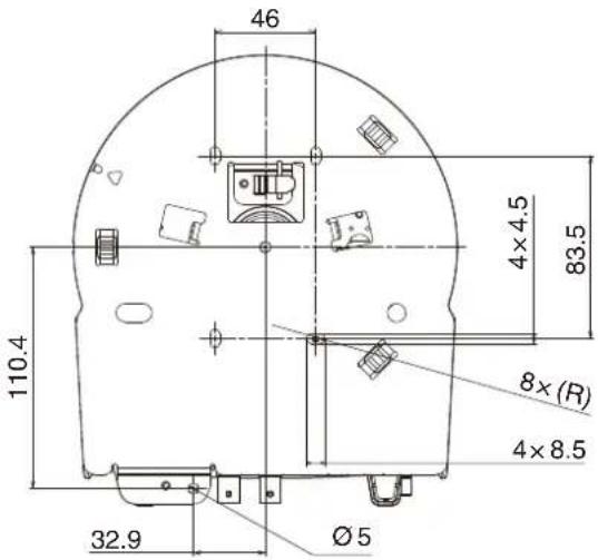
The camera can be installed using a ceiling mount, standing mount, desktop setup, or a tripod.

This section explains how to install the camera using a ceiling mount. Configure other installation methods as needed.
1 Drill a hole in the ceiling for the safety wire (hereafter referred to as the safety wire hole).
Ensure the distance between the safety wire hole and the ceiling plate's hole is less than 100 mm.

2 Pass the safety wire through the safety wire hole drilled in step 1, and securely attach it to an anchor or structural component.

3
Using the wire stopper, attach the safety wire to the hole in the ceiling plate.

4
Securely attach the ceiling plate to the ceiling using four M4 screws (commercially available), and adjust the length of the safety wire.
When attaching the ceiling plate, ensure that the safety wire hangs vertically down from the anchor or structural component (see Figure A).
Also, the length of the wire extending from the safety wire hole should be less than 100 mm (see Figure B).


Note
• Install the ceiling plate within ±5° relative to the horizontal plane.
- The ceiling plate cannot be installed on vertical surfaces such as walls.
5 Adjust the length of the safety wire and secure the wire stopper using a (commercially available) screwdriver and M3x6L screws.

6 If necessary, pull out the logo plate and change its orientation.

7 Use a screwdriver and a M3x4L screw to attach the Camera-to-Mount Safety Wire to the camera body.

8 Pass the Camera-to-Mount Safety Wire through the slit (①) and attach it to the hook on the rear side (②).
To remove the wire, loose the hook fixing screw (★) 1 and move the wire upward and downward to release from the hook 2

9 Attach the ceiling plate and the camera body.
Align the recessed part on the side of the base with the ▲ mark on the ceiling plate (①), then rotate the base clockwise (②)

Important
- When installing the camera, hold the base section of the camera body. Holding or moving the camera head by hand may cause damage.
- Make sure the camera body and ceiling plate are securely attached.
10 Use a screwdriver and a M3x4L screw to secure to the ceiling plate.

11 Connect the power supply and any necessary cables.
To prevent accidental disconnection, pass the compact power adapter cable through the cable clamp.


Important
Before connecting cables to the 12G-SDI OUT terminal N400, TIME CODE terminal , GEN-LOCK/SYNC terminal N400 , or 3G-SDI OUT terminal, be sure to connect the power supply of the camera. Also, always disconnect the cables before turning off the power.
Chapter 2
Before Use
This chapter explains the software related to the camera and examples of system configuration. It also describes the preparation and settings after installing the camera.
Security Checking/Settings
The security function of the OS or web browser may block the setting and operation of the camera.
Check the security settings beforehand, and change the settings if required.
Checking the Firewall Settings (Windows)
To use the software on a computer with Windows Defender Firewall enabled, it is necessary to add each piece of software as an application that allows communication through the firewall.

Note
If applications were not added in this procedure, they can still be added as allowed applications in the [Windows Security Alert] dialog that appears when starting the software.
1 Click [Windows Defender Firewall] in [Control Panel] > [Systems and Security].
2 Click [Allow an app or feature through Windows Defender Firewall].
3 Click [Change Settings] > [Allow another app].
4 Select [CameraSearchTool.exe] downloaded from homepage, and click [Add].
Initial Camera Settings
In order to use the camera, it is necessary to first connect the computer to the camera via network then complete the initial setup, including setting the Administrator Account.
This section explains how to use the Camera Search Tool and how to open the camera's initial settings screen directly on a web browser. Use the Multi-Camera Management Application to perform the initial settings for multiple cameras. For details, refer to the User Manual of the Multi-Camera Management Application.

Note
Even if you have not configured the initial settings, HDMI/SDI video is output and can be used for simple operation checks and other tasks as long as a LAN cable is not connected.
Settings using the Camera Search Tool
Use the Camera Search Tool to access the camera's initial settings screen and perform the initial settings for factory-set cameras.
Camera detection by this tool is valid only for cameras in the same network.
1 Connect the camera to the computer on the same network, then turn on the power.
2 Once downloaded from the Canon website, double click the Camera Search Tool file.
Windows: CameraSearchTool.exe
macOS: Camera Search Tool.app
When starting this tool, cameras on the same network are automatically detected and the acquired information is displayed in a list.
In the case the camera is not automatically detected, click [Search Camera].

Note
- Even if the network addresses of the computer and the camera are different, if IPv6 of the computer is enabled, the camera will be detected using the IPv6 link-local address.
- If IPv6 is not available, either assign an IPv4 address on the DHCP server or use the AutoIP feature to detect the camera. To use the AutoIP function, after performing the following settings, connect the computer and camera to a network environment without a DHCP server. Each computer and camera will be assigned an IPv4 link-local address of 169.254.xxx.xxx and will belong to the same network, so the camera can be detected.
Windows: Set [Obtain an IP address automatically] in the network settings.
macOS: Set [Configure IPv4] to [Using DHCP] in [System Preferences] > [Network].

Click the IP address of the camera to be set up.
![Search Camera MAC Address IPv4 Address IPv6 Address AutoIP.Model Name Serial Number [1] 08-83-91-91-91-91 --- (Akt2: 08.0007.78.0007.8.0) --- CR-N400 81.85.0007.08.1](/content/2026/07/1492718/images/0dfe67d6354e506bfbbcad8173f254891b4b362f2a44094641b51e3fed7e3747.jpg)
The web browser starts and the [Default Settings (1/2)] screen of the camera is displayed.
4 Enter the Administrator Name and Administrator Password, select [Language], and click [Apply and Reboot].

After rebooting the camera, the user name and password input dialog is displayed.
![CANON CR-N400 - Enter the Administrator Name and Administrator Password, select [Language], and click [Apply and Reboot]. - 2](/content/2026/07/1492718/images/df9454e85a04d654626fe49a027abef6dd17104348ac10607cb3436133c2c6dd.jpg)
Important
To ensure system security, set the administrator password that should not be easily guessed by third parties. Be sure not to forget the new password.
5 Enter the user name (administrator name) and password (administrator password), and click [OK].

The [Default Settings (2/2)] screen of the camera is displayed.
6 Set the [Environment], [USB Camera], [Network], [Date and Time], and [Online Update], then click [Apply] or [Apply and Reboot].

After the camera reboots, the Settings Page is displayed and settings are able to be configured. If the [Network] settings are changed, the camera may be unable to be connected from the operating web browser. In this case, confirm the set network settings and its connected computer then reconnect. For details on the settings, refer to "System Settings" (P. 78).
![CANON CR-N400 - Set the [Environment], [USB Camera], [Network], [Date and Time], and [Online Update], then click [Apply] or [Apply and Reboot]. - 2](/content/2026/07/1492718/images/efce3fcbb8aa7ce23df9c0fb2c57951c3e45c3bbb0d27ae43dca682d508e277c.jpg)
Note
- The video size and frame rate options for the output video are determined according to the set frame frequency. and maximum resolution.
- When using the camera as a USB camera, set the frame frequency to 59.94 Hz or 50.00 Hz. To control the camera via IP, enable [IP Connection].
7 Repeat steps 3 to 6 to initialize multiple cameras.
To exit the camera search tool, click [Exit] in the menu or click the ✗ button of the window.
Camera's Settings Page from the Web Browser
Able to access the camera by directly specifying the IP address from a web browser.
If there is an IP address assigned by the DHCP server, specify it, otherwise specify "192.168.100.1".

Important
- Able to access with the IP address of 192.168.100.1 approximately 2 minutes after connecting the camera to the network environment.
- If an IPv4 address is assigned by the DHCP server, it will switch to that address and access by 192.168.100.1 will not be possible.
- If there are devices with 192.168.100.1 on the same network, the same IP address will be assigned, and access to the camera with 192.168.100.1 will not be possible.
1 When accessing with 192.168.100.1., set the IP address of the computer.
Set the IP address of the computer to the same network as 192.168.100.1 such as 192.168.100.xxx.
2 Launch the web browser.
3 Enter the camera's IP address in the address column of the web browser and press [Enter].
The [Default Settings (1/2)] screen of the camera is displayed.
4 Perform steps 4 to 6 of the previous section "Settings for the Camera Search Tool".
After the camera reboots, the Settings Page is displayed and settings are able to be configured.
If necessary, restore the computer settings changed in step 1.
Chapter 3
Camera Setup
The settings required to use the camera are made on the Settings Page. Before starting operation, make various settings on the Settings Page according to the shooting conditions and purpose. There are also menus that can be performed during operation, such as camera maintenance.
Follow the steps below to connect to cameras either by wires or wirelessly and to display the Settings Page.
Accessing from a Web Browser
Follow the steps below to display the Settings Page according to the connection method to the camera (wired or wireless LAN).
Generally, the Settings Page is accessed using a guest user account. For details on setting user privileges, refer to "User Authority" (P. 107).

Important
- If you forget the administrator account, reset to factory default settings (P. 146). However, because the Administrator Account and other settings will be initialized, it will no longer be able to connect to the camera as it is. Use the Camera Search tool to perform initialization setting.
- To ensure security, close the web browser after completing the settings using the Settings Page.
- Do not open multiple Setting Pages at one time and try to change the settings of a single camera.
For Wired LAN
Enter the IP address configured in "Initial Camera Settings" (P. 31) directly into your web browser to display the camera's Settings Page.
1 Launch the web browser.
2 Enter the IP address and press Enter
The Settings Page is displayed.
For Wireless LAN
Even when using with a wireless LAN, it is necessary to first connect with a wired LAN and configure the wireless LAN settings.
1 Display the Settings Page according to the procedure in the previous section "For Wired LAN"
2 Enable wireless LAN.
Click the [System] tab and set [Wireless LAN] to [Enable] in [Communication] > [Wireless LAN], configure [Access Point] and [IPv4], then restart the camera.

For details, refer to [System] > [Communication] > [Wireless LAN] (P. 95).
3 Connect devices (computers and mobile devices) to be used to the camera
Enable the wireless LAN settings on devices to be used and connect to the access point with the SSID that was configured in step 2.
4 Re-display the Settings Page by following the procedure in the preceding section in "For Wired LAN"
Enter the IP address configured in step 2.
■ Cautions and Troubleshooting for Wireless LAN Connection
If experiencing "Slow down of network speed" or "lost connection" while using a wireless LAN, refer to the following examples.
How to install network devices (Wireless LAN support)
- When using a wireless LAN indoors, install the camera and network device in the same room.
- Install the camera and network device in a location with good visibility, where there is no interference from people or objects.
- Place the camera and network device as close to each other as possible. If necessary, change the installation height and orientation.
Surrounding Electronic Devices
- If the network speed becomes slow due to the influence of nearby electronic devices (radio interference), changing the channel may solve the problem.
- IEEE 802.11 b/g/n wireless LANs use the same 2.4 GHz frequency band as microwave ovens, cordless phones, wireless microphones, and Bluetooth devices. This slows down the network speed if these devices are in the vicinity.
- If an access point that uses the same frequency band as the camera is operating nearby, the network speed will be slower.
Using Multiple Cameras
- Do not duplicate IP addresses of devices in the same network.
- To reduce radio interference, set a four-channel interval for the wireless LAN, for example, "1, 6, 11", "2, 7, 12", or "3, 8, 13".
The configuration of the Settings Page is as follows:
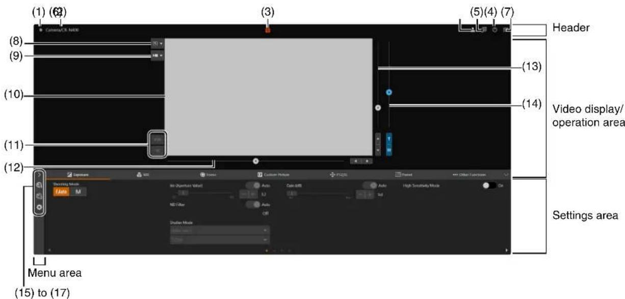
Settings area (When [Camera Control 1] is selected)

Settings area (When [Camera Control 2] is selected)

Header
This area is common to all Settings Pages.
(1) Tally Lamp Status Display
Displays the video distribution status on the Tally Lamp.
: Distributing
: Preparing for distribution
☐: No distribution
(2) Camera Name / Model Name
Displays the camera name and the model name of the connected camera.
(3) High Temperature Warning Display
Displayed when the internal temperature rises.
(4) Switch Account
Switch the account used to access the camera. To access the camera as a guest, check [Guest User].

(5) Select Language
Set the language to be displayed on the Settings Page
(6) Power ON/Standby
Switches between the camera on and standby mode. Set it to standby mode if required to stop HDMI/SDI output or IP distribution of videos.
If ⏻ is clicked while the camera is on, "This will switch to standby. Do you want to continue?" message will appear. Click [OK] and "On Standby" will appear in the video display area and will go into standby mode. Click [Start Up] to return to the power on state.
The power lamp on the front of the camera is as follows:
On (green): Power on
On (orange): Standby
Blinking (green): Changing to or from standby
(7) Menu
Click to display a list of items in the settings area.
For details on the items, refer to "Settings Area" (P. 39) and "Menu Area" (P. 39).
When using an account without camera control privileges, only [Video] and [System] can be selected. If [Video] is selected, the settings area and operation area are not displayed (only the video display area is displayed).
■ Video Display/Operation Area
Displays the video received from the camera. Also, operates the pan, tilt, and zoom of the camera.
(8) Click Operation Menu
Select the operation performed when clicking on the video display area. Available operations will differ depending on the camera settings.

[Pan/Tilt]: operates the camera angle (P. 40).

[Zoom]: operates the zoom (P. 40).

[Crop]: operates the cropping frame (P. 66).

[Focus]: focus related operations such as moving the focus frame or tracking (P. 53).

[Off]: no operation.
(9) Video Update Frequency (fps)
Sets the update frequency for the video display. When set to [Off], the image is not displayed.
(10) Video Display Area
JPEG video is displayed.
When the image cannot be displayed, the Reconnect button appears in the center of the screen.
(11) Start/Stop RTMP/SRT streaming
Starts or stops streaming when RTMP (P. 98) or SRT (P. 99) communication is available. Operate with an administrator account.
(12) Pan Slider (P. 40)
Move the camera angle left or right. Use the ◀r button to fine-tune the position.
(13) Tilt Slider (P. 40)
Move the camera angle up or down. Use the ▲r button to fine-tune the position.
(14) Zoom Slider (P. 40)
Move up to zoom in (telephoto) or down to zoom out (wide angle).
Use the T or W button to fine-tune the position.
Menu Area
Display camera settings and shooting assistance function setting items on the settings area, or configure system settings. Click and select a menu, or click each icon to switch the displayed menu.
(15) [Camera Control 1] menu
Sets camera related settings.
(16) [Camera Control 2] menu
Sets shooting assistance settings.
(17) [System] menu (P. 78)
Configure advanced camera system settings such as video and audio, server, communications, and security. If this tab is clicked, the video display/operation area disappears, and the screen will be configured with the setting item category and the settings screen.
Settings Area
Change camera settings. Select a menu from the left side of the settings area (except for the [System] menu, P. 39), and click each tab to switch the settings area.
(18) [Exposure] tab (P. 42)
Sets exposure settings.
(19) [WB] tab (P. 47)
Sets the white balance settings.
(20) [Focus] tab (P. 49)
Sets focus settings.
(21) [Custom Picture] tab (P. 54)
Sets custom picture settings.
(22) [BTZ/IS] tab (P. 61)
Sets pan, tilt, and zoom operations and image stabilizer settings.
(23) [Breset] tab (P. 62)
Sets the preset settings.
(24) [Other Functions] tab (P. 65)
Sets the color bar output and Add-On settings.
(25) [Crop] tab (P. 66)
Sets crop related settings.
(26) [Monitoring] tab (P. 67)
Sets monitoring settings.
(27) [OSD] tab P. 73
Sets onscreen displays settings.
Sets assistance settings.
Important
Do not use the [Back] and [Forward] buttons on the Web browser to navigate through the settings page. The changed settings may be reverted or unintended changes may be applied.
Note
- By clicking √ at the right of the tab area, the Settings area will be hidden, and only the video display/operation area will be displayed.
It will be reverted by clicking
- If the width of the screen is narrow, tabs can be switched by using the ◀ buttons. Also, for each Settings area, it is possible to switch the display by using the ◀ buttons at the bottom of the screen or by clicking .
Camera Operation
Set the camera angle by operating the camera's pan, tilt and zoom.

Note
Camera control by clicking and dragging does not guarantee exact precision.
Operation by Clicking on the Video Display Area or by Slider
- Click and Drag Operation
When the click operation is set to [Pan/Tilt], if you click on the video display area, the camera angle moves so that the position of the mouse pointer is at the center. Also, dragging on the video display area operates the pan/tilt of the camera. If a single click or drag does not result in the desired camera angle, repeat the operation.
When the click operation is set to [Zoom], you can zoom by dragging and dropping on the video display area to specify the zoom area. When you specify an area from left to right, the selected area is displayed across the entire video display area. When you specify it from right to left, the view zooms out so that the center of the selected area aligns with the center of the video display area.
Slider Operation
Dragging the pan and tilt slider knobs pans and tilts the camera.
Drag the zoom slider knob to operate the zoom.
The slider knob moves even if clicking the slider on the point without the knob.

Fine tune the pan, tilt, and zoom positions by clicking the ◀r , ▶or ▲or T or W buttons.
Slider Operation When Using the Digital Zoom and Digital Tele-Converter
When [PTZ/IS] > [Digital Zoom] is set to [400x] , the digital zoom area is displayed on the zoom slider and digital zoom operation is enabled.
![Digital zoom area Optical zoom area (even for options that combine optical zoom and additional processing like [Advanced 40x]).](/content/2026/07/1492718/images/fe1daf46eaf4d0b06212fb67ba1bfd46cdfa4ea6ed928415e3d8e82679abb46a.jpg)
When [PTZ/IS] > [Digital Zoom] is set to [Digital Tele-Converter] (P. 61), the video is magnified according to the magnification selected, but the position of the slider does not change.
Depending on the [Digital Zoom Upper Limit] (P. 88) settings, the digital zoom area may not be displayed.
Exposure Settings
Settings for the shooting mode according to the shooting environment and subject, as well as the ND filter, iris, shutter speed, and gain.
To display the [Exposure] tab, select the [Camera Control 1] menu to the left of the settings area.

[Shooting Mode]
Switches the shooting mode according to the shooting environment and subject.
FAuto (Full Auto)
The exposure (iris, shutter speed, gain, etc.) and white balance settings are adjusted automatically.
M (Manual Exposure)
The exposure (iris, shutter speed, gain, etc.) is adjusted manually.

Note
- When the shooting mode is set to (E/Auto) each setting is set as follows.
– [Light Metering]: [Standard]
- [AE Shift]: [±0]
– [Limit for Auto Mode (dB)]: [30.0 dB]
- The items that can be set differ depending on the shooting mode. The details are shown below.
O: Items which can be set
●: Items which are set automatically
-: Items which cannot be set
| Item\Shooting Mode | FAuto | M |
| Iris ● O | ||
| ND Filter ● O* | 1 | |
| Shutter Mode ● O | ||
| Gain ● O | ||
| Limit for Auto Mode (dB) - O* | 2 | |
| High Sensitivity Mode O* | 3 O* | 3 |
| Gain Boost - O* | 3 | |
| Light Metering - O | ||
| AE Shift - O* | 3 | |
| AE Response | - O | |
| Shockless Gain | O*4 O | |
| Iris Limit | O*4 O | |
| Iris Increment | O | O |
| Fine Increment | O*4 O | |
| Shutter Increment | O | O |
| Gain Increment | O | O |
| Flicker Reduction | O | O |
| Diffraction correction | O | O |
*1 Only switchable between [Auto] and off.
*2 Can only be set when gain is set to [Auto].
*3 Refer to each item of "Exposure Settings" (P. 42) for the configurable conditions.
*4 This item can be set. but the settings are not reflected during full auto mode.
[ND Filter]
When [Shooting Mode] is set to FAuto (Full Auto), the ND filter is always adjusted automatically.
When [Shooting Mode] is set to M (Manual Exposure), you can choose to set the ND filter to [Auto] or off.
When set to [Auto], the ND filter is automatically adjusted in conjunction with the iris setting and activates when the [Iris (Aperture Value)] reaches F4.0. When adjusting exposure without using the ND filter, turn [Auto] off.
[Iris (Aperture Value)]
Adjusts the iris (aperture) according to the brightness of the subject.
When [Auto] is set, the iris is automatically adjusted.
When [Auto] is off, the iris can be manually adjusted. Moving the slider to the left opens the aperture and brightens the video. Moving it to the right narrows the aperture and darkens the video.
Following aperture values can be set.
| Iris Increment Iris* | |
| 1/3-stop | F1.8, F2.0, F2.2, F2.5, F2.8, F3.2, F3.5, F4.0, F4.5, F5.0, F5.6, F6.3, F7.1, F8.0 (F9.0, F10, F11, Closed) |
| 1/4-stop | F1.8, F2.0, F2.2, F2.4, F2.6, F2.8, F3.2, F3.4, F3.7, F4.0, F4.4, F4.8, F5.2, F5.6, F6.2, F6.7, F7.3, F8.0 (F8.7, F9.5, F10, F11, Closed) |
* The values in parentheses are only available when [Iris Limit] is set to off.
The aperture value that can be set differs depending on the zoom position. Reference aperture value is displayed on the screen.
Maximum wide angle: F1.8 to F8.0, maximum telephoto: F2.8 to F8.0
![CANON CR-N400 - [Iris (Aperture Value)] - 1](/content/2026/07/1492718/images/89ebcbe167f6984090cae299b01a963a6508f50fbdba0ae5860b44b8194c9b98.jpg)
Note
- By changing the depth of field and blur the background or surroundings to make the subject stand out, set a smaller aperture value, and to keep everything from close objects to far-away objects in focus, set a larger aperture value.
- When shooting in a bright location, narrowing down the iris can cause blurring. It is possible to prevent blurring by adjusting the ND filter and shutter speed and opening the iris.
- When [Auto] of the iris is set to off, the aperture value from Auto is inherited. The aperture value before setting to [Auto] is not restored.
[Shutter Mode]
Adjusting the shutter speed enables to adapt to the subjects and the shooting environment, making it possible to capture fast-moving subjects (sports, vehicles, etc.) clearly and brighten low-light scenes, etc. Shutter speed can be adjusted in the following modes:
[Auto (sec.)]
Automatically adjusts the shutter speed according to the brightness of the video.
[Speed (sec.)]
Sets the shutter speed to seconds. The shutter speed can also be set to a value higher than the frame rate. You can select the increment to use when adjusting the shutter speed between 1/3-stop and 1/4-stop increments.
[Slow (sec.)]
Sets the shutter speed slower than the frame rate to seconds. This setting is used for shooting in low-light areas.
Also, special effects such as "blurring the background" and "adding residual image effects to zoom" are available for shooting a moving subject with pan operation.
For precautions when shooting in slow, refer to "About Shooting with Slow Shutter" (P. 46).
[Clear Scan (Hz)]
Sets the shutter speed by frequency. This is used to reduce black bands on the screen, flickering from fluorescent lighting, and to fine tune the brightness.
[Angle (°)]
You can set the shutter angle to determine the shutter speed.
[Off]
The camera uses a standard shutter speed based on the frame frequency.
The shutter speed that can be selected differs depending on the frame frequency.
| Shutter Mode | Frame Frequency (Hz) | |||||
| 23.98 29.97 | 59.94 25.00 50.00 | |||||
| Auto (sec.) | 1/24 - 1/2000 | 1/30 - 1/2000 | 1/60 - 1/2000 | 1/25 - 1/2000 | 1/50 - 1/2000 | |
| Speed (sec.) | 1/3-stop increments | 1/24 - 1/2000 | 1/30 - 1/2000 | 1/60 - 1/2000 | 1/25 - 1/2000 | 1/50 - 1/2000 |
| 1/4-stop increments | 1/24 - 1/2000 | 1/30 - 1/2000 | 1/60 - 1/2000 | 1/25 - 1/2000 | 1/50 - 1/2000 | |
| Slow (sec.) | 1/3, 1/6, 1/12 | 1/4, 1/8, 1/15 | 1/4, 1/8, 1/15, 1/30 | 1/3, 1/6, 1/12 | 1/3, 1/6, 1/12, 1/25 | |
| Clear Scan (Hz) | 23.98 - 1998 | 29.97 - 1998 | 59.94 - 1998 | 25.00 - 2003 | 50.00 - 2003 | |
| Angle (°) | 360°, 240°, 180°, 120°, 90°, 60°, 45°, 30°, 22.5°, 15°, 11.25°Angles equivalent to 1/120 sec., 1/100 sec., 1/60 sec., 1/50 sec., 1/40 sec., 3/100 sec., 1/30 sec. and 1/25 sec. can also be set. | |||||
| [Off] | 1/24 | 1/30 | 1/60 | 1/25 | 1/50 | |
![CANON CR-N400 - [Shutter Mode] - 1](/content/2026/07/1492718/images/e6057d1a56dab3df5e6aff989b81d0dd429324106931b8ebbd8408878d2478e0.jpg)
Note
- When shooting in a bright location, narrowing down the iris can cause blurring. It is possible to prevent this phenomenon by performing the following operations.
- Setting [ND Filter] to [Auto] (P. 43).
– Using a faster shutter speed and opening the iris.
- When the shutter mode is set to [Slow (sec.)], bright red, green or blue dots may appear on the screen. In such case, use a faster shutter speed or select a lower gain value (P. 44).
[Gain (dB)]
You can set the amplification amount of the video amplifier.
When [Auto] is set, the iris is automatically adjusted. By setting [Limit for Auto Mode (dB)], the maximum gain value can be limited.
When [Auto] is off, manual adjustment is possible. The adjustment range is as follows:
| Increments | Available Setting Values*1 |
| [Normal] (3 dB) | 0.0 dB to 30.0 dB, 36.0 dB*2 |
| [Fine] (0.5 dB) |
*1 Available values will depend on the gamma curve component of the [Gamma/Color space] setting in the custom picture file.
[Wide DR], [Canon Log 3] or [Canon 709]: 8.5 dB to 30.0 dB
[PQ]: 4.0 dB to 30.0 dB
[HLG]: 3.5 dB to 30.0 dB
[BT.709 Standard]: 0 dB to 30.0 dB
*2 Only when using the [Gain Boost] setting (P. 45).
![CANON CR-N400 - [Gain (dB)] - 1](/content/2026/07/1492718/images/b0a3ad39e0003be1c7051089dbd6a3b5602656e6fa487cb43b4793f073aedad6.jpg)
Note
- Increasing the gain may cause a slightly grainy screen.
- Increasing the gain may cause bright red, green or blue dots to appear on the screen. In such case, use a faster shutter speed (P. 43) or select a lower gain value.
[Limit for Auto Mode (dB)]
By limiting the maximum value when the gain is set to [Auto], you can curb the amount of noise and keep a dark ambient. Adjustment is done in 1/2 stop (0.5 dB) increments. The adjustable range differs depending on the gamma curve component of the [Gamma/Color Space] setting in the custom picture file.
[Wide DR], [Canon Log 3] or [Canon 709]: 8.5 dB to 30.0 dB
[PQ]: 4.0 dB to 30.0 dB
[HLG]: 3.5 dB to 30.0 dB
[BT.709 Standard]: 0.0 dB to 30.0 dB
![CANON CR-N400 - [Limit for Auto Mode (dB)] - 1](/content/2026/07/1492718/images/85197b6262d2dafabfc52ebcfcbbbfc2d472a79ebba1178d07171e9cf3704849.jpg)
Note
- When the shooting mode is FAuto (Full Auto), the [Limit for Auto Mode (dB)] value will not be applied. It will be limited by the maximum values below. Maximum 30.0 dB
- When using [Limit for Auto Mode (dB)], set the following settings on the Remote Camera Controller.
- RC-IP100: [AGC Limit]
- RC-IP1000: [AGC Limit (dB)]
[High Sensitivity Mode]
Using the high sensitivity mode allows for brighter shooting, useful when shooting in dark environments.
[Gain Boost]
When set to [On], the gain value will be fixed to 36.0 dB. Can only be set when [Gain (dB)] is set to manual.
![CANON CR-N400 - [Gain Boost] - 1](/content/2026/07/1492718/images/c56cb464696e7dc08fec305908a9357144ad1b07e9fe91b7a7de02333b746d37.jpg)
Note
- Setting [Gain Boost] to [On] may cause a grainy screen and bright red, green or blue dots to appear on the screen.
- If [Gain (dB)] is set to [Auto], gain boost mode will end.
[Light Metering]
When one of the [Iris (Aperture Value)], [Shutter Mode] or [Gain (dB)] is set to Auto, and the metering mode is set to match the shooting scene, it is possible to shoot with more appropriate brightness.
[Standard]
Meters the entire screen while focusing on the subject in the center of the screen.
[Backlight]
Controls darker areas of the screen more brightly when shooting backlight scenes.
[Spotlight]
Controls the brightness of the subject in the spotlight.
[AE Shift]
When one of the [Iris (Aperture Value)], [Shutter Mode] or [Gain (dB)] is set to auto, the exposure can intentionally be compensated to capture subjects either at a brighter or darker exposure. Move the slider to a negative value to darken the image, or to a positive value to lighten it. Adjustment can be made in the range of -2 levels to +2 levels (by 0.25).
[AE Response]
Select the response of AE when one of the [Iris (Aperture Value)], [Shutter Mode] or [Gain (dB)] is set to Auto. The set values are High, Normal, and Low in order of the shortest time to achieve the proper exposure.
[Shockless Gain]
Makes the change in the image look smoother when adjusting the [Gain (dB)] level manually. The setting values that define how long it takes for the gain value to change are High, Normal, and Low in order of speed. When turned off, the change is immediate.
[Iris Limit]
When set to [On], the maximum aperture value (F value) can be limited.
![CANON CR-N400 - [Iris Limit] - 1](/content/2026/07/1492718/images/5858e14d601997a91afc1955227784d4efb2cdc9276ff0e048508b048d186e7a.jpg)
Note
Using aperture values that exceed the lens's diffraction limit may affect the image (for example, causing diffraction blur). Using aperture values within the lens's diffraction limit (iris limit) is recommended.
[Iris Increment]
Select the iris increment. The F values that can be set differ depending on the selected iris increment.
[Fine Increment]
When set to [On], you can use the smallest iris increment. Nevertheless, the aperture value displayed on the screen will be the closest value in the selected increment scale.
[Shutter Increment]
Selects the shutter increment to use when the shutter mode is set to [Speed (sec.)].
[Gain Increment]
Selects the increment to use when adjusting gain.
[Flicker Reduction]
When set to [On], the camera automatically detects and corrects flickering from fluorescent lights.
![CANON CR-N400 - [Flicker Reduction] - 1](/content/2026/07/1492718/images/8bd4c81432d6e9042a9ccf2b391d5a043e0f9f264f76b61cbea413b3d82db2d4.jpg)
Note
- Erroneous flicker detection may cause horizontal noise. In this case, avoid using [Flicker Reduction].
- When shooting under an artificial light source such as a fluorescent lamp, mercury lamp, or halogen light, flicker may occur in principle depending on the shutter speed set. It may be possible to suppress flicker by setting the shutter speed according to the frequency of the power supply. For 50 Hz, select 1/50 second* or 1/100 second; for 60 Hz, select 1/60 second or 1/120 second.
* Not available depending on the frame frequency.
[Diffraction correction]
When the aperture is closed down, the image produced may not be as sharp at certain apertures (diffraction). Set this setting to [On] to correct the lack of sharpness caused by diffraction.
![CANON CR-N400 - [Diffraction correction] - 1](/content/2026/07/1492718/images/febae380110a95a72961d8f05dc775771cbbc3512704b929ae05b1ca965f822f.jpg)
About Shooting with Slow Shutter
When [Shooting Mode] is set to M (Manual Exposure) and [Shutter Mode] is set to [Slow (sec.)], by using a slow shutter speed you can obtain a brighter picture even in dark surroundings. However, the following phenomena may occur depending on the scene and the subject.
- Noticeable residual image from moving subjects
– Deterioration of image quality
– White spots on the screen
– Autofocus not functioning well
WB Settings
Sets the white balance settings.
To display the [WB] tab, select the [Camera Control 1] menu to the left of the settings area.
If you click ■ you can reset the item to its default value.


Note
When [Exposure] > [Shooting Mode] is (Auto Auto), [White Balance Mode] is AWB fixed.
[White Balance Mode]
Sets white balance according to the color temperature of light sources such as illuminations and daylight. Adjustment procedure is as follows:
[AWB]
Adjust the white balance so that it is always optimal. The white balance is automatically adjusted as the color temperature of the light source changes. By activating [Lock], you can pause [AWB] (auto white balance) mode. The lock will be canceled if a different white balance setting is selected.
[Daylight]
Sets the white balance according to the daylight (approx. 5600 K). The adjustment range is 4300 K to 8000 K. You can further adjust the color compensation* value (±5 CC).
* Adjusts the color along the green/magenta gradation.
[Tungsten]
Sets the white balance according to tungsten lighting (approx. 3200 K). Use this setting when shooting under tungsten or tungsten colored fluorescent lighting. The adjustment range is 2700 K to 3700 K. You can further adjust the color compensation value ( ± 5 CC).
[Color Temperature (K)]
Specify the color temperature in range of 2000 K to 15000 K to adjust the white balance. You can further adjust the color compensation value ( ± 20 CC).
[Manual]
Set [R Gain] and [B Gain] as desired.
[Set A], [Set B]
Executing [White Balance Calibration] captures the reference white color in the actual shooting environment. Illuminate a gray card or white subject (white paper, etc.) with a light source and click [White Balance Calibration] while the subject fills the screen.
Possible to register two settings: [Set A] and [Set B].
The settings are erased after the camera is restarted or turned off/on, so register them as a preset in order to save the settings.
![CANON CR-N400 - [Set A], [Set B] - 1](/content/2026/07/1492718/images/2a645b8e35865b9b085c07c0d11bc425c77e52e44dcabc5aa66bedd342dbfd8d.jpg)
Note
- When shooting under the following conditions, if the screen color looks unnatural in [AWB], adjust the white balance using [Set A] or [Set B]:
- Shooting in locations where lighting conditions suddenly change
- Close-up shooting
- Shooting a scene with only one color, such as sky, sea, or forest
-
Shooting under mercury lamps and certain fluorescent/LED lights
-
The [White Balance] and [Color Matrix Tuning] settings in the custom picture file (P. 54) take precedence over the white balance set with these procedures.
• Color temperatures are given for reference purposes only. - If the setting is other than [AWB], and the location or brightness changes or the ND filter is switched, adjust the white balance again.
[Shockless WB]
When set to [On], makes the transition look smoother when you change the white balance settings.
[AWB Response]
Selects the responsiveness when [White Balance] is set to [AWB].
The set values in the order of the shortening time required to achieve the proper white balance are High, Normal, and Low.
![CANON CR-N400 - [AWB Response] - 1](/content/2026/07/1492718/images/63b0614ddd950dd6130de89d8232fa1a67e566e498268c7d84834b6e88fb5b2c.jpg)
Note
When [Exposure] > [Shooting Mode] is set to F.Auto (Full Auto), [AWB Response] is [Normal] fixed.
[C. Temp. Increment]
Select the units for the color temperature increment between [Mired] (5-mired increments) or [Kelvin] (100-kelvin increments). Even when [Mired] is selected, the color temperature is converted to and displayed in kelvins. Changing this setting may change the white balance setting.
Focus Settings
There are two focus adjustment modes: "Autofocus" and "Manual focus".
Switch the [AF] on in the focus mode to select the autofocus or switch it to off to select the manual focus.
The items that can be set differ depending on the focus mode.
To display the [Focus] tab, select the [Camera Control 1] menu to the left of the settings area.
Autofocus
Autofocus adjusts the focus automatically.

[Focus Mode]
Turning [AF] on switches to autofocus mode.
[Adjust Focus]
Able to adjust the focus manually even when [AF] is set to on.
Click [Near] to move the focus position to the near side, and [Far] to move the focus position to the far side. Click and hold the button to move continuously. Release the button to achieve the focus automatically again.
[One Shot AF]
Click [Execute] to automatically focus once on the subject within the AF frame.
After execution, the focus mode switches to manual focus.
[Face AF]
Sets the operation of the face detection AF (the ability to detect and focus on a person's face).
[Off]
Focuses on the center of the screen. Face detection is not performed.
[Face Det. & Tracking]
Gives priority to focus on a person's face.
- When there is a person's face in the screen
When multiple people are in the screen, the main subject is automatically determined.
The following face frame is displayed.

When there is only one face frame, ◀ and ▶ will not be displayed on the frame.
Click on a face frame to track that face (P. 53).
You can change the main subject with the [Change Main Subject] function (P. 50).
- When there is no face in the screen
Focuses on the center of the screen (P. 53).
[Face Only]
Focuses only on the person's face.
If there is a person's face in the screen, follows the procedure described in the previous section, [Face Det. & Tracking].
If there isn't any person's face in the screen, the focus is locked until a face is detected.
[Cancel Tracking]
Cancels tracking when tracking a specified subject (P. 53).
[Change Main Subject]
Changes the main subject when multiple faces or both eyes have been detected with the [Face AF] and [Eye Detection] functions. Click ◀ to move the face frame/eye frame to the left, or ▶ to move it to the right.
[Face Detection AE]
When set to [On], brightness for the detected face will be adjusted automatically.
[Eye Detection]
When set to [On], the eyes of the person determined to be the main subject will be detected, and a frame will appear on the eyes of the main subject. When both eyes have been detected, you can select either eye using the [Change Main Subject] function (P. 50).
Eye frame
![CANON CR-N400 - [Eye Detection] - 1](/content/2026/07/1492718/images/bc06973bbe557ffd3c2b0a0c228bb41645a467c4bd6a2016692db01e681301c6.jpg)
[AF Speed]
Selects the autofocus adjustment speed.
[High]
Performs AF operation at the highest speed. Effective in high-brightness and night scenes. Uses the external sensor in combination.
[Normal]
Provides smoother operation compared to [High]. Uses the external sensor in combination.
[Low]
Performs stable AF operation.
[AF Response]
Selects the responsiveness of the autofocus.
The setting values are High, Normal, and Low in order of the shortest time until the focus operation starts.
[Focus Limit]
Reduces the time to achieve the focus by limiting the focus range.
When set to [On], the focus range is limited to 60 cm (2 ft.) to ∞ (throughout the entire zoom range). When set to off, the range is 1 cm (0.39 in.; at full wide-angle) to ∞ , including the macro area.
Autofocus
- The focus position for autofocus varies slightly depending on the shooting conditions such as the subject, brightness, and zoom position. Check the focus again before shooting.
- Focus adjustment can take a while when the frame frequency is 29.97 Hz, 25.00 Hz, or 23.98 Hz.
- It may be difficult to focus with autofocus in certain cases.
Shooting conditions that are difficult to focus with autofocus

Strong light is reflected.

Center of the screen has little light/dark difference.

Fast
movement

Shooting through
glass with water
droplets

Night view
- When the gamma curve component of the [Gamma/Color Space] setting in the custom picture file (P. 55) is set to an option other than [BT.709 Standard]
-
When the iris is narrowed down
-
When the shutter speed is in the range of [Slow (sec.)]
- When the gain value is high
- When subjects are at both far and near sides
- The following are the main examples of failure to detect faces:
- When the face is extremely small, large, dark, or bright relative to the entire screen
- When the face is facing sideways or diagonally, or the face is upside down
- When part of the face is hidden
- The following are the main examples of failure to detect eyes:
– Under the same conditions listed as examples of failure to detect faces.
- When wearing glasses or sunglasses, or when the subject's hair is covering the eyes or the face.
- When the face is obscured by shadow, or in backlit situations.
- May detect a subject other than a person as a face by mistake. If so, set [Face AF] to [Off].
- May accidentally track another subject with similar characteristics. In this case, select the subject again.
-
Face detection AF, tracking, eye detection, or face detection AE cannot be used in the following cases.
-
When the shutter speed is slower than 1/30 second (at a frame rate of 59.94 / 29.97Hz ), slower than 1/25 second (at 50.00 / 25.00Hz ), or slower than 1/24 second (at 23.98Hz ).
- When [PTZ/IS] > [Digital Zoom] is set to [400x] and the image size is magnified by more than 80 times
- When [PTZ/IS] > [Digital Zoom] > [Digital Tele-Converter] is set to [6.0x]
- Face detection AE cannot be used in the following cases.
- When shutter speed, gain and aperture are set to manual.
- When the light metering mode is set to [Spotlight].
Manual Focus
Manual Focus makes the focus position move manually.


Note
- If a zoom operation is performed after focusing, the focus may shift.
- If the camera is left turned on, the focus may shift due to increase of the temperature of the lens and inside the camera body. Check the focus again before shooting.
[Focus Mode]
Turning [AF] off switches to manual focus mode.
[Adjust Focus]
Click [Near] to move the focus position to the near side, and [Far] to move the focus position to the far side. Click and hold the button to move continuously.
[One Shot AF]
The settings are the same as for "Autofocus" (P. 49).
[Touch Operation]
Select the operation performed when clicking on the video.
For screen operations, refer to "Clicking on the Screen" (P. 53).
[Select Tracked Object]
You can display a tracking frame around a subject by clicking on it in the screen.
Can be selected when [Face Detection] is set to [On].
[Touch AF]
Focuses on the position clicked on the screen.
[Face Detection]
When set to [On], if there are people's faces on the screen, the focus guide frame will be displayed on the face of the person judged to be the main subject. For details on screen operation when there are no faces detected in the screen, refer
to "Clicking on the Screen" (P. 53).
[Cancel Tracking]
The settings are the same as for "Autofocus" (P. 50).
[Change Main Subject]
Changes the main subject when multiple faces or both eyes have been detected with the [Face Detection] and [Eye Detection] functions. Click ▶ to move the face frame/eye frame to the left, or ▶ to move it to the right.
[Face Detection AE]
The settings are the same as for "Autofocus" (P. 50).
[Eye Detection]
The settings are the same as for "Autofocus" (P. 50).
[MF Speed]
Selects the manual focus adjustment speed (amount of focus movement when [Near] or [Far] is clicked.).
![CANON CR-N400 - [MF Speed] - 1](/content/2026/07/1492718/images/e2f2ad9738da4bb5cea437d6e0e76f08f0c9660d0d109ce1f4f681f89ed1577a.jpg)
Note
- When the [Iris (Aperture Value)] is set to [Auto], it may take a while for the response of the focus to stabilize after a zoom operation.
- Focus may not operate correctly. Refer to "Shooting conditions that are difficult to focus with autofocus" (P. 50).
-
[Touch AF] and face detection are not available in the following cases.
-
When the shutter speed is slower than 1/30 second (at a frame rate of 59.94 / 29.97Hz ), slower than 1/25 second (at 50.00 / 25.00Hz ), or slower than 1/24 second (at 23.98Hz ).
- When [PTZ/IS] > [Digital Zoom] is set to [400x] and the image size is magnified by more than 80 times
- When [PTZ/IS] > [Digital Zoom] > [Digital Tele-Converter] is set to [6.0x]
[Focus Limit]
The settings are the same as for "Autofocus" (P. 50).
By clicking on a person or subject in the screen, you can keep the focus locked on that main subject even if it moves. This is called tracking.
When [Face AF] is [Off]
The subject in the center of the screen stays in focus and the AF frame will not be displayed.
When [Face AF] is [Face Det. & Tracking] or [Face Only]
When clicking on a person's face, a tracking frame appears on the face, and the tracking will be in progress.
![CANON CR-N400 - When [Face AF] is [Face Det. & Tracking] or [Face Only] - 1](/content/2026/07/1492718/images/d517e925f013a043b4318bc010c7fcf444703d2ee520305591e6049ee86075ec.jpg)
Tracking Frame
If something other than the face of a person is clicked, the tracking frame appears on the subject clicked in the screen and is tracked.
![CANON CR-N400 - When [Face AF] is [Face Det. & Tracking] or [Face Only] - 2](/content/2026/07/1492718/images/8e1d4b483d99f4b2aee0ceac5984a825d56dfbe4d59f02881c386a8a338c2ce9.jpg)
Note
When the tracking frame is displayed, the face frame will not be displayed.
When [Face Detection] is Off
When a subject is clicked within the screen, a white frame appears around the selected subject. After the focus is adjusted, a gray tracking frame is displayed.
When [Face Detection] is [On]
When [Touch Operation] is set to [Touch AF], clicking on a person's face will display a white frame around the face. After the focus is adjusted, a gray tracking frame is displayed.
If you click on anything other than a person's face, a white frame will appear around the clicked subject within the screen. After the focus is adjusted, a gray tracking frame is displayed.
When [Touch Operation] is set to [Select Tracked Object], a gray tracking frame will appear around the subject clicked within the screen.
Custom Picture Settings
Sets custom picture settings. By using custom picture settings, you can change many settings that control various aspects of the image produced. After adjusting the desired settings to your preference, you can save them as a custom picture file and load them later to apply exactly the same settings. You can save up to 20 custom picture files to the camera. To display the [Custom Picture] tab, select the [Camera Control 1] menu to the left of the settings area.

[CP File]
Select a custom picture file to apply its settings. By saving custom picture files to the camera, it is possible to easily select the desired image quality adjustments from the list of custom picture files. When editing/saving, renaming or protecting custom picture files, select the desired custom picture file in the same way.
The following settings are saved to custom picture files C1 to C20 as preset custom picture settings*. Custom picture files C1 to C8 are protected by default and need to be unprotected before they can be edited.
* C0 may be displayed depending on the settings when registering to the preset (P. 63).
| Preset custom picture file | [Gamma/Color Space] | [Color Matrix] | Look Files | Characteristics |
| C1:BT.709 Standard | BT.709 Standard / BT.709 | Video – | These settings are appropriate for playback on BT.709 compliant monitors. | |
| C2:Canon 709 | Canon 709 / BT.709 Neutral – | These settings produce a look appropriate also for use without post processing, featuring high contrast while ensuring a wide dynamic range for playback on BT.709 compliant monitors. | ||
| C3:Canon Log 3 | Canon Log 3 / C.Gamut | Neutral – | These settings use Canon Log 3 gamma and require postproduction processing. | |
| C4:BT.709 Wide DR | BT.709 Wide DR / BT.709 | Video – | These settings produce a wide dynamic range and are appropriate for playback on BT.709 compliant monitors. | |
| C5:PQ PQ / BT.2020 Neutral – | These settings use a high dynamic range gamma curve compliant with the PQ standard defined by ITU-R BT.2100.* | |||
| C6:HLG HLG / BT.2020 Neutral – | These settings use a high dynamic range gamma curve compliant with the HLG standard defined by ITU-R BT.2100.* | |||
| C7:EOS Standard | BT.709 Wide DR / BT.709 | Neutral On | Reproduces the image quality and look of an EOS interchangeable lens DSLR camera with its picture style set to [Standard]. | |
| C8:EOS Neutral | BT.709 Wide DR / BT.709 | Neutral On | Reproduces the image quality and look of an EOS interchangeable lens DSLR camera with its picture style set to [Neutral]. | |
| C9:User9 to C20:User20 | BT.709 Standard / BT.709 | Video – | These settings are appropriate for playback on BT.709 compliant monitors, and use a gamma curve that meets ITU-R BT.709 standards. |
* ITU-R BT.2100 is a standard for a color bit depth of 10 or 12 bits. When the output video is set to one of the 8 bit color options, the gamma curve is approximately equivalent to this standard.
![CANON CR-N400 - [CP File] - 1](/content/2026/07/1492718/images/a54efae2e1a585a91af75f61ce3827314e8d6dc9aefc5323a7cb51dc2664a1c1.jpg)
Note
About the logarithmic gamma curves (Canon Log 3 settings)
- These gamma curves require post-production processing. They were designed to make the most of the imaging sensor characteristics in order to obtain impressive levels of dynamic range.
- While shooting, you can apply a LUT to the 12G-SDI OUT terminal's N400 image or the view assistance function to the HDMI OUT / 3G-SDI OUT terminal's image to use gamma curve settings more suitable for monitoring (P. 67).
– There are also other LUTs available that can be applied for processing in post-production.
* For the latest information on available LUTs, please visit your local Canon website.

ock)]
Protecting a custom picture file prevents its settings from being accidentally changed. Click [☐ (Lock)] to protect/unprotect the custom picture file.
[Reset]
Resets the settings of the selected custom picture file (P. 59).
[CP File Name]
Rename the selected custom picture file.
![CANON CR-N400 - [CP File Name] - 1](/content/2026/07/1492718/images/6ef9754f3cafe7c7d7a42e5248f7fb4ebf4201b5b490e613610eca0306dfc403.jpg)
Note
The characters that can be used in a file name are as follows.
Characters: Single-byte alphanumeric characters
Symbols: ! " # \$ % & ' ( ) * + , - . / : ; < = > ? @ [ \ ] ^ _ { | } \~
[Gamma/Color Space]
Combination of gamma curve and color space settings that affects the overall look and color space of the image.
Canon Log 3 / C.Gamut, Canon Log 3 / BT.2020, Canon Log 3 / BT.709, Canon 709 / BT.709, BT.709 Wide DR / BT.709, BT.709 Standard / BT.709, PQ / BT.2020, HLG / BT.2020
Gamma
[Canon Log 3]:
Logarithmic gamma curve that keeps the characteristics of the [Canon Log] setting while expanding its dynamic range. Requires image processing in post-production.
[PQ]: HDR (high dynamic range) gamma curve compliant with the PQ standard defined by ITU-R BT.2100.*
[HLG]: HDR (high dynamic range) gamma curve compliant with the HLG standard defined by ITU-R BT.2100.*
[BT.709 Wide DR]:
Gamma curve with a very wide dynamic range. Optimized for playback on BT.709 compliant monitors. Equivalent to the [Wide DR] setting in previous camera models.
[BT.709 Standard]:
Gamma curve that meets ITU-R BT.709 standards, for playback on BT.709 compliant monitors. Equivalent to the [Normal 3] setting in previous camera models.
[Canon 709]:
Gamma curve appropriate also for use without post processing, featuring high contrast while ensuring a wide dynamic range. Use this when outputting to a BT.709 compliant monitor.
* ITU-R BT.2100 is a standard for a color bit depth of 10 or 12 bits. When the output video is set to one of the 8 bit color options, the gamma curve is approximately equivalent to this standard.


Color space
[C.Gamut]:
Color space developed by Canon based on the specific characteristics of the camera's imaging sensor. It covers a wider color gamut than that of BT.2020.
[BT.2020]:
Color space that meets ITU-R BT.2020 standards, which defines parameters for ultrahigh-definition television (4K/8K).
[BT.709]: Standard color space that is compatible with ITU-R BT.709 specifications.
[Color Matrix]
Select the video's image tone.
[Neutral]
Reproduces neutral colors.
[Production Camera]
Reproduces colors more suitable for motion picture production.
[Video]
Reproduces colors with a contrast suitable for TV broadcasting.
[HLG Color]
Changes the quality of color reproduction when using the hybrid log gamma (HLG). This setting is only available when [Gamma/Color Space] is set to [HLG / BT.2020].
[BT.2100]
Color reproduction according to ITU-R BT.2100 specifications.
[Vivid]
More saturated color reproduction according to the 'Traditional Colour' approach in ITU-R BT.2390.
[Edit]
Detailed custom picture settings related to image quality. Click ✗ on the upper right corner of the settings area to finish editing.
If you click I you can reset the item to its default value.

[Black: Master Pedestal]
Adjusts the black level.
Higher settings will make dark areas brighter but decrease contrast. This setting is not available when the gamma curve component of the [Gamma/Color Space] setting is set to [Canon Log 3].
[Black: Master Black Red], [Black: Master Black Green], [Black: Master Black Blue]
These settings correct the color cast in blacks.
These settings are not available when the gamma curve component of the [Gamma/Color Space] setting is set to [Canon Log 3].
[Black Gamma: Level], [Black Gamma: Range], [Black Gamma: Point]
These settings control the lower part of the gamma curve (dark areas of the image). By changing each value, the gamma curve on the black side within the range shown in the figure below is adjusted.
These settings are only available when the gamma curve component of the [Gamma/Color Space] setting is set to BT.709 Standard.
– [Level]: Raises or lowers the lower part of the gamma curve.
– [Range]: Selects the adjustment range from the selected [Point].
– [Point]: Determines the shape of the lower part of the gamma curve.

[Knee: Activate], [Knee: Automatic], [Knee: White Level 100%], [Knee: Slope], [Knee: Point], [Knee: Saturation]
Compresses the highlighted areas to suppress the occurrence of blown highlights. These settings are only available when the gamma curve component of the [Gamma/Color Space] setting is set to BT.709 Standard.
– [Activate]: Enables knee adjustment.
– [Automatic]: Enables automatic knee adjustment.
- [White Level 100%]: Adjusts automatically to keep output at 100% even if [Point] is changed.
– [Slope]: Indicates the slope of the knee.
– [Point]: Indicates the knee point.
– [Saturation]: Adjusts the color intensity in the highlighted areas.
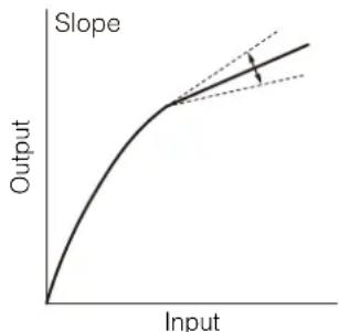

[Low Key Saturation: Activate], [Low Key Saturation: Level]
Specifies how saturated colors are in dark areas.
- [Activate]: Set this setting to [On] to enable the adjustment of color saturation in dark areas with the [Level] setting.
– [Level]: Specifies how saturated colors are in dark areas.
[Sharpness: Level]
Adjust the level of edge enhancement.
[Sharpness: Detail Frequency]
Sets the center frequency of horizontal sharpness. Setting higher values increases the frequency, which, in turn, increases the sharpness.
[Sharpness: Coring Level]
Sets the level of correction of artifacts caused by high sharpness levels (coring). Higher values prevent sharpness from being applied to minute details, resulting in less noise.
[Sharpness: Limit]
Adjusts the level at which the edge enhancement is limited.
[Noise Reduction]
When set to [Auto], the noise reduction level is automatically adjusted.
[S/N Priority]
When [Noise Reduction] is set to [Auto] and [S/N Priority] is set to [On], the image quality is adjusted with the noise reduction prioritized.
![CANON CR-N400 - [Black Gamma: Level], [Black Gamma: Range], [Black Gamma: Point] - 4](/content/2026/07/1492718/images/a31c7197cf4c497f8d823190c63a10c83f6b9008b000f2986ab5cb57411d2019.jpg)
Note
Depending on the scene, the entire screen may appear soft, or an afterimage may appear on a moving subject.
[Noise Reduction: Spatial Filter]
Reduces noise by applying a soft focus-like effect on the entire picture. When set to a value other than [0], afterimages are not produced but the whole image will have a softer look.
[Noise Reduction: Frame Correlation]
Reduces noise elements by comparing the current image to the previous one (field). When set to a value other than [0], the perceived resolution will not be affected but an afterimage may appear for moving subjects.
[Skin Detail: Effect Level], [Skin Detail: Assist], [Skin Detail: Hue], [Skin Detail: Chroma], [Skin Detail: Area], [Skin Detail: Y Level]
The camera applies a softening filter to areas in the picture with skin tones to give a more pleasant appearance.
- [Effect Level]: Adjusts the level of the filter. Three adjustment levels are available, with [High] being the maximum setting.
- [Assist]: When set to [On], a zebra pattern will appear on the screen or video output terminal over areas of the image that are detected as having skin tones.
– [Hue]: Adjusts the hue for detection of skin tones.
– [Chroma]: Adjusts the color saturation for detection of skin tones.
– [Area]: Adjusts the color range for detection of skin tones.
– [Y Level]: Adjusts the brightness for detection of skin tones.
[White Balance: R Gain], [White Balance: G Gain], [White Balance: B Gain]
These settings adjust the amount of white balance throughout the whole image by changing the intensity of red tones ([R Gain]), green tones ([G Gain]) and blue tones ([B Gain]).
[Over 100%]
Determines how the camera handles video signals exceeding 100%. This setting is not available when the gamma curve component of the [Gamma/Color Space] setting is set to one of the [Canon Log 3], [PQ], [HLG] or [Canon 709] options.
– [Through]: Leave the signal unchanged.
– [Clip]: Clip the signal at 100%.
– [Press]: Compress a signal of up to 108% down to 100% levels.
[Color Matrix Tuning: Gain], [Color Matrix Tuning: Phase], [Color Matrix Tuning: R-G], [Color Matrix Tuning: R-B], [Color Matrix Tuning: G-R], [Color Matrix Tuning: G-B], [Color Matrix Tuning: B-R], [Color Matrix Tuning: B-G]
Adjusts the tint of the picture.
– [Gain]: Adjusts the color intensity.
– [Phase]: Adjusts the color phase of the color matrix.
– [R-G]: cyan/green and red/magenta
– [R-B]: cyan/blue and red/yellow
– [G-R]: magenta/red and green/cyan
– [G-B]: magenta/blue and green/yellow
– [B-R]: yellow/red and blue/cyan s
– [B-G]: yellow/green and blue/magenta
[Color Correction: Select Area]
The camera detects areas with certain color characteristics and corrects them. You can set the color correction for up to two different areas (A and B) and apply the color correction to either one or both of them.
[Color Correction: Assist]
While color correction is activated, parts of the image that are not detected as having the characteristics specified for area A or B will appear colorless on the image output from the output terminals and the IP streaming video (except when adjusting the [Revision Level]/[Revision Phase] settings).
[Area A: Setting Phase], [Area A: Setting Chroma], [Area A: Setting Area], [Area A: Setting Y Level], [Area A: Revision Level], [Area A: Revision Phase]
[Area B: Setting Phase], [Area B: Setting Chroma], [Area B: Setting Area], [Area B: Setting Y Level], [Area B: Revision Level], [Area B: Revision Phase]
– [Area A: Setting Phase], [Area B: Setting Phase]: These settings determine the color phase of the area to be corrected (A or B, respectively).
- [Area A: Setting Chroma], [Area B: Setting Chroma]: These settings determine the color saturation of the area to be corrected (A or B, respectively).
- [Area A: Setting Area], [Area B: Setting Area]: These settings determine the color range of the area to be corrected (A or B, respectively).
- [Area A: Setting Y Level], [Area B: Setting Y Level]: These settings determine the brightness of the area to be corrected (A or B, respectively).
– [Area A: Revision Level], [Area B: Revision Level]: These settings adjust the amount of correction applied to the color saturation in the corrected area (A or B, respectively).
– [Area A: Revision Phase], [Area B: Revision Phase]: These settings adjust the amount of correction applied to the color phase in the corrected area (A or B, respectively).
![CANON CR-N400 - [Color Correction: Assist] - 1](/content/2026/07/1492718/images/02c29607990c2e9056ff8aa9f76f3c746321cf7260b28a93ad3c1e807cc44db6.jpg)
Note
- When [High Sensitivity Mode] (P. 45) or [Gain Boost] (P. 45) is set to [On], the effect cannot be achieved in certain ranges of [Low Key Saturation: Level].
- Depending on other menu settings, you may not be able to obtain the desired image effect even after changing the custom picture settings.
[Look File]
You can register LUT files created with Blackmagic Design's DaVinci Resolve as Look Files in the custom picture file. Using a Look File allows you to adjust the video quality of the video. These adjustments apply also to output terminals.
When set to [On], the image quality adjustments set in the Look File will be applied.
- Resetting Custom Picture Files
1 Click [Reset].
The settings screen is displayed.
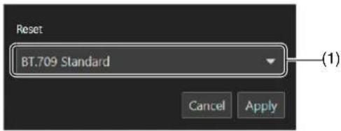
(1) Preset
Select the desired preset custom picture settings.
2 Select any of the preset settings and click [Apply].
The settings of the selected custom picture file are reset.
Registering a Look File
1 Click [Register].
The settings screen is displayed.

(1) [Look File]
Displays the selected Look File.
(2) [Gamma/Color Space With Look File]
Select the [Gamma/Color Space] setting to use after the Look File is applied.
2 Click [...] and specify the Look File to register.
3 Select [Gamma/Color Space With Look File] and click [Apply].
The selected Look File will be loaded and registered in the custom picture file. The image quality adjustments set in the Look File will be applied.
- Deleting Look Files
1 Select the custom picture file with the registered Look File to delete.
2 Click [Delete].
A confirmation message is displayed.
3 Click [Apply].
The Look File registered in the custom picture file will be deleted.
![CANON CR-N400 - Click [Apply]. - 1](/content/2026/07/1492718/images/9a4cbaa86364b56cbf1d81d292b8edb99b101ac25fb7b4e76559f6ca755b6e4f.jpg)
Note
- About Look Files
- The camera supports LUT Files (3D LUT / .cube format) in 17 grid or 33 grid format created with Blackmagic Design's DaVinci Resolve.
- LUT files with input ranges outside the 0 to 1 range in the header ("LUT_3D_INPUT_RANGE") are not supported.
- LUT files which include values outside of the 0 to 1 range in the data area are not supported.
- LUT files 2 MB and larger, as well as files with a name containing over 65 characters are not supported.
– The characters that can be used in a file name are as follows.
Characters: Single-byte alphanumeric characters
Symbols: ! " # \$ % & ' ( ) * + , - . / : ; < = > ? @ [ \ ] ^ _ { | } \~
- If the correct input/output gamma curve and color space conversion are not selected, video will not be output correctly.
- A Look File cannot be used if the [Gamma/Color Space], [HLG Color] or [Over 100%] settings are changed after registering it.
- When the gamma curve component of the [Gamma/Color Space] setting in the custom picture is set to either [BT.709 Standard] or [BT.709 Wide DR], super-white (video signal above 100%) and superblack (video signal below 0%) levels of brightness will be clipped. When the video signal contains super-white brightness levels, select [Edit] > [Over 100%] > [Press] and then activate the Look File to apply it to a signal compressed to 100%.
- It may take some time to load Look Files.
PTZ/IS Settings
Settings for the camera's pan, tilt, and zoom operations and image stabilizer.
To display the [PTZ/IS] tab, select the [Camera Control 1] menu to the left of the settings area.

[Digital Zoom]
Select whether to use digital zoom ([400x]), the [Digital Tele-Converter] function or advanced zoom ([Advanced 40x]: the camera can zoom up to 40x combining the optical zoom and additional processing).
When [System] > [Video and Audio] > [Movement Range] > [Digital Zoom Upper Limit] is set, the maximum zoom ratio will be displayed in the digital zoom option.
![CANON CR-N400 - [Digital Zoom] - 1](/content/2026/07/1492718/images/7aad760002c86aa9dd78cb4555dc2b71bddde80a9a97b7a84dbc660704dbd63c.jpg)
Note
The advanced zoom setting can only be used when [System] > [Environment] > [Maximum Resolution] is set to [1920 × 1080] (P. 117).
[Digital Tele-Converter]
When [Digital Zoom] is set to [Digital Tele-Converter], select the magnification of the focal length.
Because the image is processed digitally, the video is coarser over the entire zoom range.
[Pan/Tilt Acceleration]
Select the degree of acceleration of the pan/tilt operation.
[Soft Zoom Control]
Slowly accelerates when zooming starts and decelerates when zooming stops.
[Image Stabilizer]
Select whether to use a function that reduces the blurring of videos caused by camera vibration.
[Standard] corrects relatively small blurs.
[Powered IS] corrects blurring during telephoto shooting. The closer the zoom is to the telephoto side, the greater the correction effect.
![CANON CR-N400 - [Image Stabilizer] - 1](/content/2026/07/1492718/images/ca02d2ff5c1ebaf380961e7190d853ebd003f33cc3090b60a26b96c303715b6a.jpg)
Note
- If the blurring is too large, it may not be corrected completely.
- Swing back may occur when the pan/tilt stops.
- For pan and tilt, the anti-vibration effect is smaller than compared to when not operating.
Preset Settings
By registering preset camera settings such as camera angle, exposure, and image quality, it is possible to easily call the presets and execute the settings.
To display the [Preset] tab, select the [Camera Control 1] menu to the left of the settings area.
Registering Presets
1 Click the [Preset] tab on the settings page
Displays the preset settings.
2 Click the preset number field to register, and click [Add] to register.

The settings screen will pop up.
3 Set the preset items and click [Add]

(1) [Preset Name]
Enter a preset name.
(2) [PTZF], [Camera Settings]
Check the items to preset.
| Item Preset target | |
| PTZF Pan/Tilt/Zoom position | [Focus] [PTZ/IS] > [Digital Zoom], [Soft Zoom Control], [Pan/Tilt Acceleration] |
| Camera Settings [Exposure]* | [WB] [CP] > [CP File] or image quality settings. [PTZ/IS] > [Image Stabilizer] |
* Excluding [Gain Boost].
(3) [Speed Mode]
Select the speed specification method by [Time] or [Speed Level].
(4) [Time (sec.)], [Speed]
Sets the pan/tilt speed and zoom speed (using time or speed) for a registered preset.
(5) [Create/Update Thumbnail]
Displays the image at the time of registration in the preset list as a thumbnail. Uncheck this check box if you do not need to display thumbnails, or if you do not wish to update thumbnails when a preset is edited.
The preset is saved to the camera and displayed in the list as follows:

The at the bottom of the thumbnail means that the presets include a PTZF setting.
that the presets include a camera quality setting.
For presets with unregistered thumbnails, the following icon is displayed.
![CANON CR-N400 - [Create/Update Thumbnail] - 2](/content/2026/07/1492718/images/7c0dfbab21a65bbd2e5099c355548c5f1243ab167076b2a1143fcc0f6a7b7d5f.jpg)
4 Repeat steps 2 to 3 to register multiple presets.
Note
- [home] is the setting when the camera was launched (home position). It can be overwritten but cannot be deleted.
- If [Camera Settings] under [home] > [Edit] is not checked, the camera settings will be saved periodically. Therefore, if you turn off the power immediately after changing the camera settings, the most recent camera settings may not be saved.
- Able to register up to 100 presets (including home position) in the camera.
- If the thumbnail is not updated when a preset is edited, the displayed thumbnail may differ from the actual preset state.
- Registered Custom Picture Settings
If you set [Camera Settings] as the preset target, the custom picture settings that are saved depend on whether or not a Look File is registered, and the [System] > [Camera Control] > [CP Storage Details of Preset (when Look File is not Registered)] setting.
| CP Storage Details of Preset (when Look File is not Registered) | Registering Presets | Executing Presets | ||
| Look File | Registered | - | Saves CP number | Applies the current image quality setting of the registered CP number |
| Not registered | CP No. | |||
| CP image quality setting | Saves custom picture quality settings | Applies the image quality set at registration* | ||
* The image quality setting is reflected in C0. If changed to [CP No.] in this state, it becomes C1. When the [CP Storage Details of Preset (when Look File is not Registered)] setting is changed, the image quality when the preset is executed may differ from the one at the time of registration.
Calling Presets and Speed Specification
Select the preset to call from the list and click [Execute] to reflect the preset settings on the camera.
Confirm in the video display area. You can also set the display method shown during preset movement.
The speed at which the camera moves to the pan/tilt/zoom position can be specified as the one set when registering the preset or a different one.
1 Select the preset to call from the list and set [Speed Specification] to either off or [On].

Set [Speed Specification] to off to use the time or speed level set when registering the preset.
If set to off, continue from step 3.
If set to [On], continue from step 2.
2 Select [Speed Mode] > [Time] or [Speed Level] and adjust the value using the slider.

If you specify a speed that differs from the one set when registering the preset, select [Time] or [Speed Level].
3 Set [Freeze Image During Movement].
If set to [On], you can display a still image of the video (set at the time movement starts) during preset movement. You can also change the default value (P. 110).
4 Click [Execute].
The camera moves to the pan/tilt/zoom position at the speed specified in step 1 or 2.

Note
- If the pan/tilt/zoom or focus of the camera is operated while a preset is running, the preset stops. However, another preset can be called while a preset is running.
- If [Stop] is clicked while a preset is running on a camera, the preset stops.
- Depending on the relationship between the pan/tilt/zoom position before the call and the registered pan/tilt/zoom position, and the [Time] setting, it may not operate within the set time.
- Camera settings other than the pan/tilt/zoom position settings are reflected immediately when [Execute] is clicked.
- If you perform one of the following operations when a still image is being displayed, the displayed image returns to the normal video display.
- Changing the HDMI/SDI signal output format (video size/frame rate, mapping) settings.
- Setting color bars to [On].
- If you input a sync signal to the GEN-LOCK/SYNC terminal N400 and execute a preset before synchronization is stabilized, still images will not be displayed.
If a sync signal is input to the GEN-LOCK/SYNC terminal while a still image is displayed, synchronization will start when the still image display ends.
Deleting Presets
Select the preset to delete from the list and click [Delete] to delete it from the camera.
Other Functions
Configure the color bar output and Add-On settings.
To display the [Other Functions] tab, select the [Camera Control 1] menu to the left of the settings area.

[Color Bars]
Outputs color bars, useful when adjusting the color and brightness settings of an external monitor.
To set the color bar type, select [System] > [System] > [Camera] > [Color Bar Type].
![CANON CR-N400 - [Color Bars] - 1](/content/2026/07/1492718/images/a36f2892ff17d0221fa4aab875186c43dd3824f2506cebd53cb0536d8a3c8d01.jpg)
Note
- When color bars are being output, functions that cannot be set appear in gray.
• Color bars cannot be output in the following cases.
- When the gamma curve component of the [Gamma/Color Space] setting in the custom picture file is set to an option other than [BT.709 Wide DR], [BT.709 Standard] or [Canon 709].
- When [System] > [Video and Audio] > [IP Streaming Video] > [Mainstream] > [Video Size] is set to [1080x1920] or [720x1280].
[Switch Video Frame Rate: HDMI/SDI]
When [Frame Frequency (Hz)] is set to 59.94 Hz, you can switch the output video frame rate of the 12G-SDI OUT terminal N400 and HDMI OUT terminal / 3G-SDI OUT terminal to the equivalent of 24 fps or 30 fps.
[Add-On] (P. 113)
Click [View] to display a list of the running applications.
When you click [Open] for the application you want to use, [Add-On Top Page] is displayed, where you can configure the application settings.

Crop Settings
Settings related to screen cropping. It is possible to crop an area of the screen and output it from the 12G-SDI OUT terminal N400, HDMI OUT/3G-SDI OUT terminal or IP streaming (except for Substream 2). Up to three cropping areas can be set. The resolution of the output image is set using the [System] > [Video and Audio] > [HDMI/SDI] > [HDMI/SDI Shared] and [Crop] settings (P. 81), and the [System] > [Video and Audio] > [IP Streaming Video] > [Mainstream] setting (P. 83). To display the [Crop] tab, select the [Camera Control 2] menu to the left of the settings area.


Note
- The crop function can only be used when [System] > [Environment] > [Maximum Resolution] is set to [3840x2160] (P. 117).
- The image output from the HDMI OUT terminal and the 3G-SDI OUT terminal will be the same.
- Cropping settings are also reflected when the camera is turned on.
[Output: 12G-SDI] N400, [Output: HDMI/3G-SDI], [Output: IP]
Select the area to output to the 12G-SDI OUT terminal N400, HDMI OUT/3G-SDI OUT terminal, or IP streaming.
When set to [Full Screen], the image will be output without cropping.
[Touch Operation Target]
Selects the screen area to operate. The cropping frame can only be moved within the selected area.
Additionally, you can change the area sizes for the Crop 1 and vertical crop frame. The area size for the Crop 2 frame varies depending on the Crop 2 resolution (P. 82, P. 84).
[View]
When set to [On], the cropping frame is displayed on the screen. Even if the cropping frame is not displayed, the cropped image will be output to the 12G-SDI OUT terminal N400, HDMI OUT/3G-SDI OUT terminal or IP streaming.
■ About the cropping frame
When the click operation menu (P. 38) is [Crop], click the screen to move the cropping frame to that position (the clicked position being the center of the frame). You can also move the cropping frame by dragging it to the desired position when the mouse pointer inside the cropping frame is
To change the area size of the cropping frame, drag a corner (☐) or the sides of the frame (when the mouse pointer is for) to adjust it to the desired size.

Note
- The cropping frame cannot be moved outside of the screen.
- The aspect ratio of the cropping frame is fixed to 16:9 (or 9:16 for vertical crop).
- The position of the Crop 2 frame returns to the center of the screen when the resolution of Crop 2 (P. 82, P. 84) is changed.
Monitoring Settings
Configure HDMI/SDI output video signal settings.
To display the [Monitoring] tab, select the [Camera Control 2] menu to the left of the settings area.

[LUT: 12G-SDI] N400, [View Assist: HDMI/3G-SDI]
While shooting using special gamma curves, you can apply a LUT to the image output from the 12G-SDI OUT terminal N400 to change the gamma/color space to a standard one. Additionally, by activating the view assistance function you can change the gamma/color space of the image output from the HDMI OUT terminal / 3G-SDI OUT terminal to be equivalent to BT.709 Wide DR/BT.709. When set to [On], the LUT/View Assistance function is applied. Whether or not the available LUT/View Assistance function can be applied depends on the [Gamma/Color Space] and [Look File] settings (changing these settings, or switching custom picture presets will turn off the LUT/View Assistance function) in the custom picture file (P. 54).
LUT
N400
List of LUTs
| Applied LUT | Gamma | Color space | Description |
| [CMT 709] CMT 709 BT. 709 | LUT for viewing on external monitors compatible with BT.709 specifications. It produces a look suitable for a cinema production, keeping a wide dynamic range without clipping when log recording. | ||
| [Canon 709] Canon 709 BT.709 | These settings produce a look appropriate also for use without post processing, featuring high contrast while ensuring a wide dynamic range for playback on BT.709 compliant monitors. | ||
| [CMT DCI] CMT DCI DCI-P3 | LUT for viewing on external monitors that support color spaces and gamma curves that follow the guidelines established by DCI (Digital Cinema Initiatives). It produces a look suitable for a cinema production, keeping a wide dynamic range without clipping when log recording. | ||
| [CMT PQ] CMT PQ BT.2020 | LUT for viewing HDR (high dynamic range) images on external monitors compatible with the PQ standard defined by ITU-R BT.2100. It produces a look suitable for a cinema production, keeping a wide dynamic range without clipping when log recording. | ||
| [CMT HLG] CMT HLG BT.2020 | LUT for viewing HDR (high dynamic range) images on external monitors compatible with the HLG standard defined by ITU-R BT.2100. It produces a look suitable for a cinema production, keeping a wide dynamic range without clipping when log recording. | ||
| [User LUT1] to [User LUT4] | Registered gamma curve | BT.709, BT.2020, Unchanged | LUT used to check the registered gamma curve, as well as the color space and range settings on a screen. |
Available LUTs
| Custom picture file Available LUTs | |||||||
| Look Files | [Gamma/Color Space] after the Look File is applied | [CMT 709] | [Canon 709] | [CMT DCI] | [CMT PQ] | [CMT HLG] | [User LUT1] to [User LUT4] |
| Off – | See the following table (A) | ||||||
| [On] | [Conform to Custom Picture] | ||||||
| [SDR BT.709] - - - - - | |||||||
| [SDR BT.2020] - - - - - | |||||||
| [HDR PQ (BT.2100)] ● ● | - | - | - | - | |||
| [HDR HLG (BT.2100)] ● | ● | - | - | - | |||
Available LUTs (A)
| Custom picture file | Available LUTs | |||||
| [Gamma/Color Space] | [CMT 709] | [Canon 709] | [CMT DCI] | [CMT PQ] | [CMT HLG] | [User LUT1] to [User LUT4] |
| [Canon Log 3 / C.Gamut] | ● | ● | ● | ● | ● | ● |
| [Canon Log 3 / BT.2020] | ● | ● | - | ● | ● | ● |
| [Canon Log 3 / BT.709] | ● | ● | - | - | - | ● |
| [Canon 709 / BT.709] | ---- | -- | ||||
| [BT.709 Wide DR / BT.709] | ---- | -- | ||||
| [BT.709 Standard / BT.709] | ---- | -- | ||||
| [PQ / BT.2020] | ● | ● | - | - | - | - |
| [HLG / BT.2020] | ● | ● | - | - | - | - |
View Assistances
List of View Assistances
| Applied View Assistance | Gamma | Color space | Description |
| [CMT 709] | Equivalent to CMT 709 | Equivalent to BT.709 | Changes the image for viewing on external monitors compatible with BT.709 specifications. It produces a look suitable for a cinema production, keeping a wide dynamic range without clipping when log recording. |
| [Canon 709] | Equivalent to Canon 709 | Equivalent to BT.709 | Changes the image for viewing on external monitors compatible with BT.709 specifications. It produces a look suitable for use without post processing, featuring high contrast while ensuring a wide dynamic range. |
Available View Assistances
| Custom picture file Available View Assistances | |||
| Look Files | [Gamma/Color Space] after the Look File is applied | [CMT 709] [Canon 709] | |
| Off – | See the following table (B) | ||
| [On] | [Conform to Custom Picture] | ||
| [SDR BT.709] – – | |||
| [SDR BT.2020] – – | |||
| [HDR PQ (BT.2100)] ● ● | |||
| [HDR HLG (BT.2100)] ● ● | |||
Available View Assistances (B)
| Custom picture file Available View Assistances | ||
| [Gamma/Color Space] | [CMT 709] | [Canon 709] |
| [Canon Log 3 / C.Gamut] | ● | ● |
| [Canon Log 3 / BT.2020] | ● | ● |
| [Canon Log 3 / BT.709] | ● | ● |
| [Canon 709 / BT.709] | - | - |
| [BT.709 Wide DR / BT.709] | ||
| [BT.709 Standard / BT.709] | ||
| [PQ / BT.2020] | ● | ● |
| [HLG / BT.2020] | ● | ● |

Note
- If the view assistance function is applied, the signal output will use narrow range (video range) coding.
- The colors modified by using this function are an approximation, and differ from the colors obtained when you set [Gamma/Color Space] in the custom picture file (P. 54) to [BT.709 Wide DR / BT.709].
- If the view assistance function is applied, the colors in the dark areas / highlights of the image may not be displayed accurately.
[HDR → SDR Gain (dB)]
When using HDR*, you can adjust the SDR gain difference relative to HDR when a LUT or view assistance function that changes the color space to BT.709 is applied to the output.
* When the [Gamma/Color Space] setting in the custom picture file is set to [PQ / BT.2020] or [HLG / BT.2020], or when the [Gamma/Color space] setting after applying a Look File is set to [HDR PQ (BT.2100)] or [HDR HLG (BT.2100)].
[User LUT] N400
You can register Look files to the camera and apply them to the video output from the 12G-SDI OUT terminal N400. You can adjust the output color space and range of user LUTs.
Registering a User LUT
1 Click the number field of the user LUT to be registered, then click [Register].

The settings screen is displayed.

(1) [User LUT Name] Enter a user LUT name.
(2) [LUT] Select a LUT file.
Note
The characters that can be used in a file name are as follows.
Characters: Single-byte alphanumeric characters
Symbols: ! " # \$ % & ' ( ) * + , - . / : ; < = > ? @ [ \ ] ^ _ { | } \~
2 Click [...] and specify the LUT file to be registered.
3 Select the color space for the output signal ([Color Space (Output)]).
To leave the color space unchanged, select [Do Not Convert] instead.
4 Select the output range ([Range (Output)]).
5 Click [Register].
Editing a User LUT
1 Click the number field of the user LUT to be edited.
2 Click [Edit].
The settings screen is displayed.
3 Change the settings as needed.
4 Click [Register].

Note
The LUT file specified when registering a user LUT cannot be specified again. Register a new user LUT.
- Deleting a User LUT
1 Select the number field of the user LUT to be deleted.
2 Click [Delete].
A confirmation message is displayed.
3 Click [Apply].
The selected user LUT will be deleted.
[Range (Canon Log): 12G-SDI] N400, [Range (HDR): 12G-SDI] N400, [Range (Canon Log): HDMI/3G-SDI], [Range (HDR): HDMI/3G-SDI]
You can select the output range of video signals (when using log gamma or PQ/HLG HDR) output from the 12G-SDI OUT terminal N400DMI OUT / 3G-SDI OUT terminal.
Applied output range settings
| Custom picture file Applied range settings | |||
| Gamma Look Files | [Gamma/Color Space] after the Look File is applied | [Range (Canon Log): XXXX], [Range (HDR): XXXX] | |
| [Canon Log 3] | Off – | [During Canon Log output] | |
| [On] | [Conform to Custom Picture] | ||
| [PQ] [HLG] | Off – | [During HDR output] | |
| [On] | [Conform to Custom Picture] | ||
| [Canon 709] [BT.709 Wide DR] [BT.709 Standard] | Off – | -Fixed narrow range) | |
| [On] | [Conform to Custom Picture] | ||
| - | [ | [SDR BT.709] | |
| [SDR BT.2020] | |||
| [HDR PQ (BT.2100)] | [During HDR output] | ||
| [HDR HLG (BT.2100)] | |||
12G-SDI OUT Terminal N400
[Full Range]
The signal output will use full range coding.
[Narrow Range]
The signal output will use narrow range (video range) coding.
HDMI OUT Terminal or 3G-SDI OUT Terminal
[Full Range Priority]
The signal output will use full range coding whenever possible but will change the range automatically according to the capabilities of the connected monitor.
[Narrow Range]
The signal output will use narrow range (video range) coding.

Note
Settings will change depending on the gamma curve component of the [Gamma/Color Space] setting in the custom picture file and the [Gamma/Color Space] setting after a Look File has been applied. When a LUT is applied, settings will change also depending on the gamma curve selected for the output signal. If a user LUT is applied, the output range will be determined by the user LUT's [Range (Output)] setting.
OSD Settings
Settings for the onscreen displays superimposed on the HDMI/SDI output video signal. To display the [OSD] tab, select the [Camera Control 2] menu to the left of the settings area.

[OSD Output: 12G-SDI] N400, [OSD Output: HDMI/3G-SDI]
When set to [On], onscreen displays are superimposed on the HDMI/SDI output video signal.

Note
When the area to output set in [Crop] settings (P. 66) is set to an option other than [Full Screen], onscreen displays cannot be superimposed.
[DISP Level]
Selects the amount of information shown over the image.
[DISP Level 1]
All onscreen displays. You can choose between [All Displays] or [All Displays (Periph. Border)]. When set to [All Displays (Periph. Border)], all onscreen displays are displayed at a smaller size.

All Displays
[DISP Level 2]
Only the onscreen displays most relevant for shooting. You can select between [Shooting Information Display] and [Markers and Focus Frame Only].
[Opacity: 12G-SDI] N400, [Opacity: HDMI/3G-SDI]
You can make onscreen displays more visible or less conspicuous by changing their opacity level. A lower percentage value indicates lower opacity.
[Peripheral Border]
A peripheral border (frame) is applied and the camera's image is reduced slightly so the onscreen displays are shown mostly around it and not on top of it, partially hiding it.

All Displays (Periph. Border)
![CANON CR-N400 - [Peripheral Border] - 2](/content/2026/07/1492718/images/7bef43d6cb9584d47c2de1c6d26ddd4785aa197eeb17ae9d198048291be96ec3.jpg)
Note
When displaying the onscreen displays on the peripheral border, set the resolution in the video output configuration (P. 81) to an option other than 720x480 or 720x576.
■ About onscreen displays
There are two DISP levels to choose from when adjusting the amount/position of the information shown over the image (P. 73).

Left side of the screen
| Icon/Display Description | |
| W——O——T | Zoom (P. 40)The zoom position is an approximation and may differ from the zoom slider's position in the Settings Page (P. 40). |
| 1.5×, 3.0×Digital Tele-Converter (P. 61) | |
| Full Auto Full Auto Mode (P. 42) | |
| MF AF | Focus Mode (P. 49, P. 51) |
| [IMAGE]ce AF (P. 49) | |
| CP 00 | Custom picture file selected (P. 54) |
| C.LOG3 / FQ / MLd Wide DR C.709Std.C.Gamut / BT.2020 BT.709 | [Gamma/Color Space] setting in the custom picture file (P. 55) |
| LOOK | Look Files (P. 58) |
| ( in red ) High Temperature Warning Display | The internal temperature is rising. When one of the [OSD Output:] settings is set to [On], it will be displayed regardless of the DISP level setting. |
Top of the screen
| Icon/Display Description | |
| 000.0 m | Object distance. |
| 00:00:00.00, 00:00:00:00F / E N400 | Time code (P. 111)Time code status (P. 112) |
Right side of the screen
| Icon/Display Description | |
| 60(24)fps, 60(30)fps | Video output (P. 65) |
| Gen. | GENLOCK (P. 111) |
| 12G-SDI N400HDMI/3G-SDI3G-SDI OFF | Output TerminalTerminal output status (P. 81) |
| Level A, Level B | Mapping level (P. 82) |
| 00.00 Frame rate (P. 81) | |
| 0000x0000P, 0000x0000i Output signal (P. 81) | |
| LUT V.Assist | LUT/view assistance status (P. 67)A LUT/view assistance has been applied to the video displayed on the screen. |
| PEAK1 PEAK2 (in yellow) Peaking (P. 76) | |
| DISP• (in yellow) Output onscreen displays | |
Bottom of the screen
| Icon/Display Description | |
| 1 | Audio level meter (P. 87) |
| A/B, K, AWB00000 K ±0 | White Balance (P. 47) |
| Light Metering (P. 45) | |
| - | Exposure bar |
| AE ±0.00 AE Shift (P. 45) | |
| ND 1/00 ND filter (P. 43) | |
| A F00.0 / closed Aperture value (P. 43) | |
| A 00.0dB Gain (P. 44) | |
| HS | High Sensitivity Mode (P. 45) |
| A 1/0000.00, 000.00°, 000.00Hz Shutter Mode (P. 43) | |
| yyyy.mm.ddHH:MM | Date/time. |

Note
Onscreen displays are not superimposed on the IP streaming video.
Assistance Settings
Configure peaking and marker settings.
To display the [Assistance] tab, select the [Camera Control 2] menu to the left of the settings area.

[Peaking: 12G-SDI] N400, [Peaking: HDMI/3G-SDI]
When set to [On], the peaking function is enabled on the HDMI/SDI output video signal.

Note
Peaking cannot be used when the [Color Correction: Assist] setting in the custom picture settings (P. 54) is set to an option other than [Off].
[Peaking]
Select a detailed peaking setting.
[Peaking Details]
Detailed settings related to peaking. Click to display the settings screen.

[Peaking 1: Color], [Peaking 2: Color]
Set the color of the two peaking levels independently of each other.
[Peaking 1: Gain], [Peaking 2: Gain], [Peaking 1: Frequency], [Peaking 2: Frequency]
Set the gain and frequency of the two peaking levels independently of each other.
[Markers: 12G-SDI] N400, [Markers: HDMI/3G-SDI]
When set to [On], onscreen markers will be displayed on the HDMI/SDI output video signal.
![Center marker ([Cross 1] type) Grid marker](/content/2026/07/1492718/images/5f1d42cdf74fc09493f0d6627f90854b4be52306697ce47c45d1abc2c610ac9b.jpg)
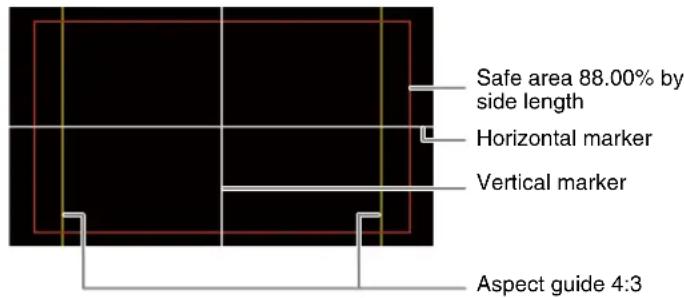
![CANON CR-N400 - [Peaking Details] - 4](/content/2026/07/1492718/images/1d0d720ca1fa7bfef946db7b9ac07534cd9d0480c2a6547993c2c8a6d7cb6c6b.jpg)
Note
Markers cannot be used when OSD output in the OSD settings (P. 73) is set to off.
[Center Marker]
Displays a marker that indicates the center of the screen. You can select between two types of cross markers, and two types of dot markers.
[Center Marker Type]
Selects the shape of the center marker.
[Horizontal Marker], [Vertical Marker]
Displays a horizontal or vertical line to help you compose level shots. You can also select the color.
[Grid Marker]
Displays a grid that allows you to frame your shots correctly (horizontally and vertically). You can also select the color.
[Aspect Marker]
Indicates various aspect ratios by displaying border lines or by masking the image outside the selected aspect ratio. The aspect ratio can be set freely by the user. A lower percentage value indicates lower mask opacity.
[Marker Aspect Ratio]
Sets the aspect ratio displayed with the [Aspect Marker] setting. By selecting [Custom], you can display the aspect marker ([Aspect Marker]) with a custom aspect ratio.
[Marker Custom Asp. Ratio]
Input the desired aspect ratio to be used when you select [Marker Aspect Ratio] > [Custom].
[Safe Area Marker]
Displays a margin from the edges of the image (using border lines or by masking the image) to indicate the action safe area, text safe area, etc. You can select the core area used as the basis for calculating the safe area and a percentage, relative to the side length or area. A lower percentage value indicates lower mask opacity.
[Basis for Marker Safe Area]
Selects the core area used as the basis for calculating the safe area when displaying [Aspect Marker].
[Whole Picture]
Sets the whole picture as the basis for calculating the safe area.
[Selected Aspect Marker]
Sets the area separated by the aspect marker as the basis for calculating the safe area.
[Marker Safe Area %]
Select the area where the safe area marker is displayed.
![CANON CR-N400 - [Marker Safe Area %] - 1](/content/2026/07/1492718/images/5d0ab01ffeef8e9eea889f045e90617845c2f55e365bcbed2ca2f154a03c4825.jpg)
Note
Aspect markers will not be displayed when the aspect ratio for [Aspect Marker] is set to [16:9] . The same applies when the aspect ratio is set manually to [1.78:1] using [Custom].
System Settings
Configure advanced camera system settings such as video and audio, server, communications, and security.
If you select the [System] menu in the settings area, the video display/operation area disappears and the following appears.
Screen Configuration
When the [System] menu is clicked, categories of the setting items are displayed on the left side of the screen, and the settings screen is displayed on the right side.
Categories of the setting items can also be displayed by clicking the ☐ at the upper right of the screen.

If the width of the screen is narrow, operations must be made from the menu since the categories of the setting items are hidden.
The system setting items are summarized as follows:
| Category Item Description | ||
| Video and audio | HDMI/SDI | Setting the common output signal method for HDMI/SDI and 3G-SDI mapping (P. 81) |
| IP Streaming Video General | settings of the video, such as video size and quality sent from the camera (P. 83) | |
| Audio Setting the bit rate for | audio input from a microphone connected to the camera or IP audio streaming (P. 86) | |
| Movement Range Pan/Tilt/Zoom movement range settings (P. 88) | ||
| Server HTTP/Video Setting the HTTP Server and video server (P. 89) | ||
| Communication | Network | Setting the network to which the camera is connected (P. 92) |
| Wireless LAN Setting the access point or IPv4 settings (P. 95) for direct connection of the camera and Wireless LAN enabled device. | ||
| External Connection (IP) | Setting the communication protocol for IP connection of the camera with external devices such as controllers (P. 97) | |
| External Connection (serial) | Settings for serial connection of the camera (P. 101) | |
| Security | Certificate Management | Settings for certificate creation and management (P. 103) |
| SSL/TLS | Encrypted communications and server certificate settings (P. 105) | |
| User Management | Add/delete and set operating privileges for administrator account information and authorized users (P. 106) | |
| Host Access Restrictions | Setting separate access controls for access from IPv4 and IPv6 addresses (P. 108) | |
| System | Camera | Settings for camera operation; camera name, installation conditions and others (P. 109) |
| Add-On (Add-On Applications System) | Management of applications installed on the camera (P. 113) | |
| Date and Time | Camera date and time settings (P. 115) | |
| Environment | Settings for the frame frequency, maximum resolution and USB camera IP connection (P. 117) | |
| Maintenance | General | Device information and settings, license verification, reboot and initialization settings (P. 118) |
| Backup/Restore | Perform backup and restoration (P. 120) | |
| Update Firmware | Perform firmware update (P. 122) | |
| Log | Log display and downloading message (P. 124) | |
Common Operations
Describes common operations in system settings.

Note
If a setting that does not display a dialog in a web browser is enabled, it may not be possible to operate the Settings Page. In this case, close and restart the web browser.
■ Applying Configuration Changes
When a setting is changed on the Settings Page, the [Apply] and [Clear] buttons in the upper right of the Settings Page are no longer grayed out and can be clicked.

In this situation, if [Apply] is clicked, the changed settings will be applied.
Click [Clear] to revert to the previous settings.
■ Changes to Settings that Require to Reboot
Settings that require the camera to be restarted for the changed settings to take effect are indicated with a green [Reboot] symbol in the beginning.

When an item that has a [Reboot] symbol is changed, [Apply] in the upper right of the Settings Page changes to [Apply and Reboot].

Click [Apply and Reboot] to apply the changes and restart the camera.
Click [Clear] to revert to the previous settings.

Important
If switched to another settings screen without clicking [Apply] or [Apply and Reboot], changes will be lost. Be sure to click [Apply] or [Apply and Reboot] to apply changes.
Setting Range and Character Limit
For setting items for numeric values and characters, the allowable range and character limit are displayed. Enter within the displayed ranges.

[System] > [Video and Audio] > [HDMI/SDI]
Settings for the output signal format of the 12G-SDI OUT N400 and HDMI OUT / 3G-SDI OUT terminals.
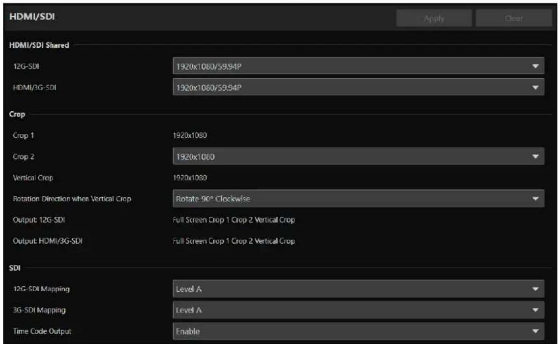
HDMI/SDI Shared
Settings for the video output signal format for the 12G-SDI OUT terminal N400 and HDMI OUT / 3G-SDI OUT terminal. 12G-SDI OUT terminal N400 settings can be set separately. However, settings for the HDMI OUT and 3G-SDI OUT terminal are shared.
[12G-SDI] N400, [HDMI/3G-SDI]
The video output format is set as a combination of the video size and frame rate.
The selectable HDMI/SDI video output format varies depending on the [Frame Frequency (Hz)] set in [System] > [System] > [Environment].
| [Frame Frequency (Hz)] | Video output configuration (video size/frame rate) | |
| 12G-SDI OUT Terminal N400 | HDMI OUT Terminal / 3G-SDI OUT Terminal | |
| 23.98 3840x2160/23.98P, | 1920x1080/23.98P 3840x2160/23.98P* | 1 , 1920x1080/23.98P |
| 29.97 3840x2160/29.97P, | 1920x1080/29.97P,1920x1080/29.97PsF | 3840x2160/29.97P*, 1 , 1920x1080/29.97P,1920x1080/59.94i* 1 /29.97PsF* 2 |
| 59.94 3840x2160/59.94P, | 1920x1080/59.94P,1920x1080/59.94i, 1280x720/59.94P,720x480/59.94i | 3840x2160/59.94P*, 1 , 1920x1080/59.94P,1920x1080/59.94i, 1280x720/59.94P,720x480/59.94P* 1 |
| 25.00 3840x2160/25.00P, | 1920x1080/25.00P,1920x1080/25.00PsF | 3840x2160/25.00P*, 1 , 1920x1080/25.00P,1920x1080/50.00i* 1 /25.00PsF* 2 |
| 50.00 3840x2160/50.00P, | 1920x1080/50.00P,1920x1080/50.00i, 1280x720/50.00P,720x576/50.00i | 3840x2160/50.00P*, 1 , 1920x1080/50.00P,1920x1080/50.00i, 1280x720/50.00P,720x576/50.00P* 1 |
*1 HDMI OUT terminal only.
*2 3G-SDI OUT terminal only.
The settings and options for each video stream vary depending on the selected video output format. See [System] > [Video and Audio] > [IP Streaming Video] for more information.
![CANON CR-N400 - [12G-SDI] N400, [HDMI/3G-SDI] - 1](/content/2026/07/1492718/images/0fabbf2883309401940c9be3277ee57d0a9766586cf8e6e09f693022105facd7.jpg)
Note
When the video size is 3840x2160 or 720x480 (720x576), video is not output from the 3G-SDI OUT terminal.
Crop
Sets output settings for the cropped areas.
[Crop 1], [Crop 2], [Vertical Crop]
Sets the resolution for each cropped area when outputting via HDMI/SDI. Depending on the [HDMI/SDI Shared] > selected video output configuration, resolution is displayed as fixed.
[Rotation Direction when Vertical Crop]
Sets the image rotation direction when outputting the vertical crop area via HDMI/SDI. This setting does not affect IP streaming video.
[Output: 12G-SDI] N400, [Output: HDMI/3G-SDI]
Available settings for [Crop] > [Output: 12G-SDI] and [Output: HDMI/3G-SDI] are displayed automatically according to the settings for [Crop 1] and [Crop 2].
![CANON CR-N400 - [Output: 12G-SDI] N400, [Output: HDMI/3G-SDI] - 1](/content/2026/07/1492718/images/106cd868cda1f65049ce638bc5e2bff16975448b65b3d6b2a2943b7836fe808f.jpg)
Note
When the resolution of [Crop 2] is changed, the resolution of Crop 2 in [System] > [Video and Audio] > [IP Streaming Video] > [Crop] will also be changed (P. 84).
SDI
Settings for the output signal method of the SDI terminals.
When the [HDMI/SDI Shared] > selected video output configuration is [1920 × 1080 / 59.94P] or [1920 × 1080 / 50.00P] , select the mapping level of the output signal of the 12G-SDI OUT N400 and 3G-SDI out terminals. A signal conforming to Level A or Level B of the SMPTE ST 425-1 standard is outputted.
[Time Code Output]
Set to [Enable] to superimpose the timecode on the SDI terminal output.
[System] > [Video and Audio] > [IP Streaming Video]
Settings for the general video settings such as size and quality for the video to be distributed via IP.
Settings are made for each of the following three streams.
- Mainstream
- Substream 1
- Substream 2
In addition, settings related to cropping.

The options for [Video Size] and [Framerate (fps)] that can be selected for each video stream vary depending on the frame frequency set in [System] > [System] > [Environment].
Mainstream
Set the Mainstream video to be distributed from the camera.
[Video Codec]
Select the video codec type.
In the following case, the video codec is H.264.
- [System] > [Communication] > [External Connection (IP)] > [RTMP] is [Enable]
![CANON CR-N400 - [Video Codec] - 1](/content/2026/07/1492718/images/d23eb19bbba85d8671285f13b53a262e31d68b1dfdbbc7cfe16c1bcda3c88f79.jpg)
Note
- If [I Frame Interval (sec.)] is set to [ALL-I], [H.265] cannot be set.
- When [Video Size] is set to [3840x2160] and [Framerate (fps)] is set to [59.94] or [50.00], cannot be set to [H.264].
[Video Size]
Select a video size.
When outputting vertical crop video, select either [1080x1920] or [720x1280].
[Framerate (fps)]
Select the frame rate of the video.
[Bit Rate Control]
Settings for the video bit rate.
In order to control the bit rate strictly in an environment subject to limitations such as the bandwidth, set to [CBR].
![CANON CR-N400 - [Bit Rate Control] - 1](/content/2026/07/1492718/images/23ce64446b06748e1e8126b4d3da06cfb835713bf51773841d2b99516b7cd2a3.jpg)
Note
When [Video Size] is set to [3840 × 2160] and [Framerate (fps)] is set to [59.94] or [50.00] , cannot be set to [CBR].
[Target Bit Rate (Mbps)]
Enter the target value of the bit rate when [Bit Rate Control] is set to [CBR].
Enter a bit rate as an image quality target when [Bit Rate Control] is set to [VBR]. Depending on the video, the set bit rate may be exceeded.
The maximum value that can be entered differs depending on the settings of [Video Size] and [Framerate (fps)].
[I Frame Interval (sec.)]
Select the interval in seconds to insert an I frame into the video selected in [Video Codec]. Specify [ALL-I] if wanting all frames to be I-frames.
![CANON CR-N400 - [I Frame Interval (sec.)] - 1](/content/2026/07/1492718/images/6292231ee647ba9c7770287a5d08e2f669a8e8be9db3b2e9339f3b4a05a4473a.jpg)
Note
When [Video Codec] is set to [H.265], [ALL-I] cannot be set.
Substream 1
Settings for the video of Substream 1 to be distributed from the camera.
[Video Codec]
H.264 is fixed.
[Video Size]
Fixed at 640x360 or 360x640. The display is automatic based on the Mainstream [Video Size] setting.
[Framerate (fps)], [Bit Rate Control], [Target Bit Rate (Mbps)], [I Frame Interval (sec.)]
Refer to each item of [Mainstream].
![CANON CR-N400 - [Video Size] - 1](/content/2026/07/1492718/images/7009019cdb66368583421eee8d98bb4dbcdf360359657defb9ab3645c909b39f.jpg)
Note
[Framerate (fps)] of Substream 1 cannot be set to [59.94] or [50.00].
Substream 2
Settings for the video of Substream 2 to be distributed from the camera.
[Video Codec]
JPEG is fixed.
[Video Size]
1280 x 720 is fixed.
[Framerate (fps)]
The set value is displayed according to the frame frequency.
Crop
Sets the cropped video streamed from the camera.
[Crop 2]
Sets the resolution for [Crop 2]. The video at the set resolution is scaled up or down to match the Mainstream or Substream 1 [Video Size] settings, and then output.
Changing this resolution also changes the resolution of [Crop 2] under [HDMI/SDI] > [Crop]. Note that it may not be displayed depending on the [Video Size] setting for [Mainstream].
[Output: Mainstream], [Output: Substream 1], [Output: Substream 2]
The selectable values under [Crop] > [Output: IP] in the crop settings (P. 66) are automatically displayed according to the configured [Video Size] for [Mainstream]. Crop video cannot be output to Substream 2.
![CANON CR-N400 - [Output: Mainstream], [Output: Substream 1], [Output: Substream 2] - 1](/content/2026/07/1492718/images/c3a28721440abe9b246614b1b1b192a54c938ea313865427ce5deb764b432cff.jpg)
Note
Also, in the following cases, the screen may become distorted.
- While displaying cropped video in IP streaming, if you change the [Video Flip] setting under [System] > [System] > [Camera] > [Installation Conditions].
- While displaying cropped video (excluding vertical crop) in IP streaming, if you turn color bars on/off.
[System] > [Video and Audio] > [Audio]
Settings for the audio input from the microphone connected to the camera and for the bit rate for IP audio streaming.

General Audio
Settings for the volume of the audio input and the type of microphone.
[Audio Input]
Select whether to use audio from the microphone.
When [Disable] is selected, Audio cannot be outputted from HDMI/SDI output.
![CANON CR-N400 - [Audio Input] - 1](/content/2026/07/1492718/images/36e7411c56a47091f4b1a37f984263ee0b76c873d761693c28c5cc706ea1d285.jpg)
Note
To set [Audio Input] to [Disable], all of the following settings must be changed to [Disable].
- [System] > [Server] > [RTP Server] > Each stream (Main, Sub1, Sub2) > [Audio Transmission]
- [System] > [Communication] > [External Connection (IP)] > [NDI|HX] > [Audio Transmission]
- [System] > [Communication] > [External Connection (IP)] > [RTMP] > [Audio Stream]
- [System] > [Communication] > [External Connection (IP)] > [SRT] > [Audio Stream]
[Audio Input Mode]
Select the type of microphone to connect to the camera: input terminals (INPUT N400/MIC), input method (LINE/MIC), and with or without power to the microphone.
| Setting Value | Input Terminal | Input Method | Power to Microphone |
| MIC Terminal/LINE MIC LINE – | |||
| MIC Terminal/MIC MIC MIC Not Supported | |||
| MIC Terminal/MIC (MIC Power On) MIC MIC Supported | |||
| INPUT Terminal/LINE N400 T LINE – | |||
| INPUT Terminal/MIC N400 | INPUT | MIC Not Supported | |
| INPUT Terminal/MIC+48V N400 | INPUT | MIC | +48V |
![CANON CR-N400 - [Audio Input Mode] - 1](/content/2026/07/1492718/images/2276e75f86b53a4a3ca3d42d30a4149142d157c16639d8f40a3555dcf582ea45.jpg)
Note
To use a microphone that requires phantom powering, turn it on while connected, and then set it to [INPUT Terminal/MIC+48V].

Important
When using a microphone, set [Audio Input Mode] correctly according to the specifications of the microphone. Failure to do so may damage the camera or microphone.
[Input Volume]
Settings for the volume to be inputted from the microphone connected to the camera.
[Current Volume Level (L)], [Current Volume Level (R)]
Displays the current volume level in the status bar.
[Attenuator]
Select whether to use the attenuator (20 dB) when the MIC input method is selected for [Audio Input Mode].
IP Audio Streaming
Features settings for IP Audio streaming.
[Distribution Bit Rate (kbps)]
Select the bit rate for distribution.

Important
• Video and audio may not be synchronized.
- Depending on the performance of the computer and the network environment, audio may be choppy.
- If using antivirus software, audio may be choppy.
- If communication is temporarily interrupted by reseating of the LAN cable for example, the audio will be disconnected. In this case, reconnect the device to the camera.
[System] > [Video and Audio] > [Movement Range]
Settings for the pan/tilt/zoom movement range.

Pan/Tilt
It is possible to limit the pan/tilt movement range.
[Movement Limit]
When set to [Enable], pan/tilt movement range for all operations is limited, including preset/trace execution and Add-On application operations.
[Upper Limit], [Lower Limit], [Left Limit], [Right Limit]
When [Movement Limit] is set to [Enable], sets or clears the pan/tilt movement limit (top, bottom, left, and right edges).
Adjust the viewing angle on the video display area and click [Set Current Value] for each edge to set the current pan/tilt position as the limit.
Click [Clear] to clear the movement limit.
Zoom
[Digital Zoom Upper Limit]
Sets the upper limit for the digital zoom.
[System] > [Server] > [HTTP/Video]
Setting for the HTTP Server for distributing Settings Page and videos over the network, and video distribution via HTTP.

HTTP Server
Settings for the authentication method and HTTP port.

Important
A confirmation dialog will appear when the [HTTP port] or [HTTPS port] settings are changed, and the connection to the camera from the active web browser may become disabled. If the changed settings are to be applied, click [OK].
If unable to reconnect to the camera from the web browser after restarting the camera, a message appears with a suggested URI, if any, to reconnect to the camera.
If unable to connect to the camera through the displayed URI, contact your system administrator.
[Authentication Method]
Select the authentication method to be used by the HTTP Server.
[HTTP Port]
Enter the HTTP port.
In general, use [80] (factory default setting).
[HTTPS Port]
Enter the HTTPS port.
In general, use [443] (factory default setting).
Video Server
Settings for clients which can connect to the Video Server.
[Maximum Number of Clients]
Enter the maximum number of clients that can connect to the camera simultaneously.
If [0] is entered, only the administrator is allowed to connect.
![CANON CR-N400 - [Maximum Number of Clients] - 1](/content/2026/07/1492718/images/db052714e23220f1a501b978382cc95cbcaf98a2aae4b4807a94e3fbccd1c111.jpg)
Important
If there are many clients to distribute, the video frame rate may decrease or the audio may be cut off.
[Maximum Connection Time (sec.)]
Enter the maximum time, in seconds, that individual client can connect to the camera.
If [0], the connection time is unlimited.
[System] > [Server] > [RTP]
Settings for video and audio streaming using RTP.


RTP Server
Settings for use of RTP, RTSP authentication method and port number.
[RTP]
Select whether to use RTP.
[RTSP Authentication Method]
Select a RTSP authentication method. Since RTSP authentication method is set independently from HTTP Server authentication method, it is necessary to configure the setting for each authentication method.
[RTSP Port]
Enter the RTSP port.
In general, use [554] (factory default settings).
[High Bit Rate Streaming]
When [Enable] is selected, it is possible to reduce distortion and frame drops in streaming video that occur when [Target Bit Rate (Mbps)] is high.
![CANON CR-N400 - [High Bit Rate Streaming] - 1](/content/2026/07/1492718/images/64085446519b5b100fe18984a6941d86eff9aae2e362298b3e3dd286fae16021.jpg)
Important
When [High Bit Rate Streaming] is set to [Enable], video may not be displayed depending on the client. In such cases, set it to [Disable].
Audio Settings
Settings for multicast audio transmission.
[Audio Compression Method]
Displays the audio compression method and the frequency. [AAC-LC 48kHz] as fixed value.
[Multicast Address]
Enter multicast address for audio transmission as follows.
IPv4: in the range of 224.0.0.0 to 239.255.255.255
IPv6: address starting with ff00::/8
[Multicast Port]
Enter multicast port for audio transmission.
[Multicast TTL]
Enter the effective range for multicast distribution.
The TTL (Time To Live), representing the effective range for multicast distribution, is decremented each time the signal passes through a router. When it reaches 0, distribution through a router becomes impossible.
For example, if TTL is set to [1], multicast distribution is confined to the local segment only and cannot pass through the router.
![CANON CR-N400 - [Multicast TTL] - 1](/content/2026/07/1492718/images/46aaf77d461f394a68c6614442c4f45cbc19d826216b31d012be387895aad05e.jpg)
Note
With one of the following settings, audio multicast distribution is disabled.
- Set [0.0.0.0] (IPv4) or [::0(:):] (IPv6) for [Multicast Address].
- Set [0] for [Multicast Port] or [Multicast TTL].
RTP Mainstream, RTP Substream 1, RTP Substream 2
Settings for RTP stream distribution, to be configured for each stream.
[Video Type]
Displays [Video Codec] and [Video Size] set for each video stream in [System] > [Video and Audio] > [IP Streaming Video].
[Multicast Address]
Enter multicast address for RTP stream as follows.
IPv4: in the range of 224.0.0.0 to 239.255.255.255
IPv6: address starting with ff00::/8
[Multicast Port]
Enter multicast port for RTP stream.
[Multicast TTL]
Enter the effective range for multicast distribution of RTP stream.
The TTL (Time To Live), representing the effective range for multicast distribution, is decremented each time the signal passes through a router. When it reaches 0, distribution through a router becomes impossible.
For example, if TTL is set to [1], multicast distribution is confined to the local segment only and cannot pass through the router.
[Audio Transmission]
Select whether to use the audio transmission of RTP stream.
When [Disable] is set for [System] > [Video and Audio] > [Audio] > [General Audio] > [Audio Input], [Enable] cannot be set.
![CANON CR-N400 - [Audio Transmission] - 1](/content/2026/07/1492718/images/31f1c74fee7d68158a84ef208e99374a74e9cde01f4a8e1ac9fe73b88be87012.jpg)
Note
- With one of the following settings, the multicast distribution of RTP stream is disabled.
- Set [0.0.0.0] (IPv4) or [::0(:):] (IPv6) for [Multicast Address].
- Set [0] for [Multicast Port] or [Multicast TTL].
- URL for RTP stream
rtsp://IP address: port/rtpstream/config1(to 3)
Example: rtsp://192.168.100.1:554/rtpstream/config1
– Distribution method depends on the request for distribution from the RTP client application.
- config1 requests the distribution of Mainstream, config2 requests Substream 1, and config3 requests Substream 2.
• Video quality of [Bit Rate Control] of Main and Sub1 uses the settings in [System] > [Video and Audio] > [IP Streaming Video] (P. 83).
- [Video Distribution] in [System]> [Security]> [User Management]> [User Authority] is not reflected in RTP.
- In an environment using proxy server or firewall, the video from the RTP stream may not be displayed. In such a case, contact your system administrator.
- When the host access restriction is applied to a client during the RTP over UDP stream distribution, it may take from a few seconds to several tens of seconds to stop the distribution.
[System] > [Communication] > [Network]
Settings for connecting to the network.


![CANON CR-N400 - [System] > [Communication] > [Network] - 3](/content/2026/07/1492718/images/d66fd214ec7c3f06e9b183ec3a5ec4b86dd91c433804ab113520aa4017b98c76.jpg)
Important
If changing settings related to network connection, it might not be possible to connect to the camera from the web browser. In this case, by clicking [Apply] or [Apply and Reboot], a dialog for confirmation will be displayed. Click [OK] to apply the change. If unable to reconnect to the camera from the web browser after the camera is restarted due to a configuration change, a message appears with a suggested URI, if any to reconnect to the camera. If unable to connect to the camera through the displayed URI, contact the system administrator.
LAN
Settings for the transmission data size from the camera.
[Maximum Packet Size]
Enter the maximum size for the packets transmitted from the camera. In general, it is not necessary to change from 1500. When using IPv6, it is necessary to set 1280 or higher.
When using ADSL, by slightly decreasing the value, transmission efficiency may be improved.
IPv4
Settings for connection to the camera by IPv4. IPv4 address can be acquired automatically from the DHCP Server or can be set manually.

Important
- Regarding [IPv4 Address], [Subnet Mask] and [IPv4 Default Gateway Address] for manual setting of IPv4, contact your system administrator.
- If there is any error in the settings of [IPv4 Address], [Subnet Mask] or [IPv4 Default Gateway Address], access via network may not be possible. In such a case, search cameras using the Camera Search Tool, and set the address again.
[IPv4 Address Settings Method]
Select the IPv4 address settings method.
For [Manual], enter a fixed IPv4 address to [IPv4 Address].
For [Auto (DHCP)], a value acquired from DHCP Server will be set automatically to [IPv4 Address (DHCP)] and [IPv4 Default Gateway Address (DHCP)].
![CANON CR-N400 - [IPv4 Address Settings Method] - 1](/content/2026/07/1492718/images/6c38ccd5080046bb30e0d3be4fa346b54992bfa579a1f85067fac18ab3500d9d.jpg)
Important
When using IPv4 address settings in [Auto (DHCP)], in an environment with a router between the DHCP Server and the camera, IPv4 address may not be assigned correctly. In such a case, select [Manual] to set the fixed IPv4 address.
[IPv4 Address]
When [IPv4 Address Settings Method] is [Manual], enter the fixed IPv4 address.
[Subnet Mask]
When [IPv4 Address Settings Method] is [Manual], enter the subnet mask value specified for each network.
[IPv4 Default Gateway Address]
When [IPv4 Address Settings Method] is [Manual], enter a value. Make sure to set, when connecting the camera to a subnet different from IP connection device such as controller.
[AutoIP]
Select whether to use AutoIP. When the AutoIP address is enabled, IP address automatically set will be displayed in [IPv4 Address (AutoIP)].
IPv6
Settings for connection to the camera using IPv6. IPv6 address can be acquired automatically from the RA or the DHCPv6 Server, or can be set manually.

Important
Regarding [IPv6 Address (Manual)], [Prefix Length] and [IPv6 Default Gateway Address] for manual setting of IPv6, contact your system administrator.
[IPv6]
Select whether to use IPv6,
[Auto (RA)]
Select [Enable], when automatically setting the address using RA (Router Advertisement, network information transmitted automatically from the router).
[Auto (DHCPv6)]
Select [Enable], when automatically setting the address using DHCPv6.
[IPv6 Address (Manual)]
For setting the address manually, enter a fixed IPv6 address.
[Prefix Length]
For setting the address manually, enter a prefix length.
[IPv6 Default Gateway Address]
For setting the address manually, enter a default gateway address. Make sure to set, when connecting the camera to a subnet different from IP connection device such as controller.
[IPv6 Address (Auto)]
When [IPv6] is [Enable] and [Auto (RA)] or [Auto (DHCPv6)] is [Enable], the address automatically acquired will be displayed.
DNS
Settings for the DNS Server address. DNS Server address can be set manually or can be acquired automatically from the DHCP/DHCPv6 Server.
[Name Server Address 1], [Name Server Address 2]
Enter the name server address to be registered. When only one address is to be registered, leave [Name Server Address 2] blank.
![CANON CR-N400 - [Name Server Address 1], [Name Server Address 2] - 1](/content/2026/07/1492718/images/3d504855683c77d43ad335d56270b93cbbc84fbfb17c37d7269c2b160a3c3e64.jpg)
Note
If [Name Server Address 1] cannot be used, make access to [Name Server Address 2]. However, it is assumed that [Name Server Address 2] set beforehand.
[Set Name Server Address Automatically]
Select the server for setting automatically the name server address.
When using DHCP, set [IPv4 Address Settings Method] to [Auto (DHCP)] (P. 92).
When using DHCPv6, set [IPv6] to [Enable] and [Auto (DHCPv6)] to [Enable] (P. 93).
[Name Server Address (DHCP)]
When [Set Name Server Address Automatically] is set as [Use DHCP] or [Use DHCP/DHCPv6], the name server address acquired from the DHCP Server will be displayed.
[Name Server Address (DHCPv6)]
When [Set Name Server Address Automatically] is set as [Use DHCPv6] or [Use DHCP/DHCPv6], the name server address acquired from the DHCPv6 Server will be displayed.
[Host Name]
The host name of the camera can be registered with alphanumeric characters to the name server.
[Search Domain]
When adding a domain name to the search domain list, enter the domain name and click [Add].
If a domain name is specified in the search domain list, it will be handled in the form of host name + domain name simply by specifying the host name without the domain name in the specified server such as NTP and RTMP.
[Search Domain List]
Displays a list of domain names added in [Search Domain].
Queries are sent to the DNS Server in order from the top of the list of domain names.
With the ▲ button on the right, the order of the domain names can be changed.
Select a domain name and click to delete the domain name.
mDNS
Settings for use of multicast DNS. When using mDNS, IP address and host name information of the camera is notified to other hosts on the network.
[mDNS]
Select whether to use mDNS.
For using NDI|HX as a communication protocol (P. 97), set [mDNS] to [Enable].
Update Firmware
In a network environment using a proxy server, configure this setting when performing firmware online updates.
[Proxy]
Selects whether to use a proxy server.
[Proxy Server]
Enter the URL of the proxy server. Enter a URL that includes an IP address or host name.
[Proxy Port]
Enter the proxy port number.
[Proxy User Name]
Enter the user name for the proxy server.
[Proxy Password]
Enter the proxy server password.
[System] > [Communication] > [Wireless LAN]
Settings for the access point for directly connecting the camera and the wireless LAN supported devices. By setting different IP addresses for the Wireless LAN and the Wired LAN, it possible to choose and use according the purposes.

Interface
Settings for use of the wireless LAN.
[Wireless LAN]
Select whether to use the wireless LAN.
Access Point
When [Wireless LAN] is set as [Enable], set the SSID and the authentication method etc., so that the camera functions as the access point.
[SSID]
Enter the network name (SSID). Enter in single-byte alphanumeric characters, numbers, or symbols.
[Authentication Method]
Fixed as WPA2-PSK/WPA3-SAE mix.
[Password]
Enter a password for the access point. Enter in single-byte alphanumeric characters, numbers, or symbols.
[Confirm Password]
Enter the same password as above for confirmation.
[Channel Setting]
When connecting multiple devices at the same frequency, set the channel to avoid radio interference.

Note
If the SSID is changed, it is also required to change the password.
Settings of IPv4 for connecting the wireless LAN and the wired LAN at the same time.
[IPv4 Address]
Enter the fixed IPv4 address.
[Subnet Mask]
Enter specified subnet mask value for each network.
![CANON CR-N400 - [Subnet Mask] - 1](/content/2026/07/1492718/images/aabd9fcb3535ff5ae7783a10d2394c2e6062afaff26338dcaa9d534950546518.jpg)
Note
The wireless connection must be on a different subnet than the wired LAN. If the specified IP address is in the same subnet as the wired LAN, an error occurs.
[System] > [Communication] > [External Connection (IP)]
Settings for communication for connecting controllers, etc. via IP.


Standard Communication (IP)
Settings for operating the cameras from the controller connected by the standard IP communication.
[Standard Communication (IP)]
Select whether to use [Standard Communication (IP)] for the connection with the controller.
[Response Port Number]
Select whether to use a fixed port number (52381) or a source port number when communicating with the controller.
[Camera IP Settings Inquiry]
Select whether to allow the inquiry on the camera IP settings from the controller.
[Camera IP Settings Network Settings]
Select whether to allow to change the network settings of the camera from the controller.
NDI|HX
Settings for exchanging data with NDI|HX supported devices.
[NDI|HX]
Select whether to use [NDI|HX] as the communication protocol.
For setting to [Enable], go to [System] > [Communication] > [Network] > [mDNS] and select [Enable] (P. 94).
[Audio Transmission]
Select whether to use the audio transmission.
When [Disable] is set for [System] > [Video and Audio] > [Audio] > [General Audio] > [Audio Input], [Enable] cannot be set.
[Discovery Server]
Select whether to use the Discovery Server.
When set to [Enable], it notifies the Discovery Server only of the IP address and does not notify other hosts of the IP address nor hostname.
[Discovery Server IP Address]
Enter the IP address of the Discovery Server.
[Multicast Distribution]
Select whether to use the multicast distribution.
![CANON CR-N400 - [Multicast Distribution] - 1](/content/2026/07/1492718/images/697c697e25d996455f8c0191440a44c4fb7608e483196d7a931ba915fd5662c3.jpg)
Note
For multicast distribution, set the multicast distribution enabled in the NDI client side as well.
[Multicast TTL]
Enter the effective range for multicast distribution.
The TTL (Time To Live), representing the effective range for multicast distribution, is decremented each time the signal passes through a router. When it reaches 0, distribution through a router becomes impossible.
For example, if TTL is set to [1], multicast distribution is confined to the local segment only and cannot pass through the router.
[Group Settings]
Select whether to use the group settings.
When a group name to which the camera belongs is specified, the camera connects only to NDI clients with the same group name.
[Group Name], [Group List]
Enter the group name.
By clicking [Add], the entered group name will be displayed in the group list.
You can sort the list items in ascending order by clicking ↓ and in descending order by clicking ↓.
Select a group in the group list and click to delete the group.
RTMP
A communication protocol for the streaming playback of video and audio, and sending and receiving the data.
[RTMP]
Select whether to use [RTMP] as the communication protocol.
![CANON CR-N400 - [RTMP] - 1](/content/2026/07/1492718/images/b8e5b741b20afb0b68efaaa512f5847ed15b6a43fbf1d88e4621963148b91222.jpg)
Note
When [H.265] is set for [System] > [Video and Audio] > [IP Streaming Video] > [Mainstream] > [Video Codec], RTMP cannot be used.
[Video Stream]
Select the type of the video stream. Substream 2 cannot be used.
[Audio Stream]
Select whether to use the audio stream.
When [Disable] is set for [System] > [Video and Audio] > [Audio] > [General Audio] > [Audio Input], [Enable] cannot be set.
[URL]
Enter the URL of the server set on the distribution server side.
Enter the string of characters starting with rtmp:// or rtmps://.
[Verify Server Certificate]
Selects whether to verify the server certificate.
[Stream Key]
Enter the stream key set on the distribution server side.
[Streaming]
If [Connection Mode] is set to [Caller], clicking [Start] (during pause) will start the streaming, and the button will change to [Stop]. During connection or during streaming, clicking [Stop] will end the connection or streaming. You can also use the buttons on the left of the video display area.
[Reconnect when Disconnected]
Selects whether to automatically reconnect when communication is lost. Used when [Connect Automatically] is set to [Disable].
[Reconnect Period (sec.)]
Enter the time (in seconds) until reconnection stops when [Reconnect when Disconnected] is set to [Enable].
Output Tracking Data
Configures the output of camera tracking data (pan, tilt, zoom, etc.) required when using the virtual studio system in a format compliant with the free-d protocol. The supported message type is Type D1.
[Output Tracking Data]
Select whether to use the camera's Output Tracking Data.
[Client (1 to 4) IP Address]
Enter the IP address of the client that will receive the camera tracking data.
[Client (1 to 4) Port]
Enter the number corresponding to each [Client (1 to 4) IP Address].
[Camera ID]
Enter the ID that identifies the camera. Be sure to use single-byte numeric characters.
[XYZ Position Offset]
Select whether to specify the camera position.
[X], [Y], [Z]
Enter the value for each.
![CANON CR-N400 - [XYZ Position Offset] - 1](/content/2026/07/1492718/images/e1cdc15dd262515c954d411a65644737f23614318dd388932e405e246a87b525.jpg)
Note
- The data to be stored and output are as follows. When a still image is displayed during preset movement, values other than Camera ID and Checksum are not changed.
Camera ID: Stores the ID set in [Camera ID].
Camera Pan Angle / Camera Tilt Angle / Camera Roll Angle: Stores the camera angles in the format specified by the free-d protocol. – Pan: -170° to 170°
- Tilt: -30° to 100°
- Roll: Angle: 0° (fixed)
Camera X-Position / Camera Y-Position / Camera Height (Z-Position): Stores the value set in [XYZ Position Offset].
Camera Zoom: Stores Zoom type and zoom position.
Camera Focus: Stores the Focus value.
Spare/Undefined Data: Stores the iris value.
Checksum: Stores the Checksum value calculated by the method specified in the free-d protocol.
- If [G-LOCK/SYNC Term.] is [Genlock Input], packets are sent along with the genlock signal. N400
- If lag occurs in the camera tracking data's transmission interval, it may be stabilized by closing the Settings Page or stopping IP streaming.
- If you output tracking data to multiple clients, the data is sent in order starting with the lowest client number.
To avoid a delay between transmissions, use a lower client number. The amount of delay depends on the system and network conditions.
SRT
Configures settings for exchanging data with SRT (Secure Reliable Transport) compliant devices.
[SRT]
Select whether to use [SRT] as the communication protocol.
[Audio Stream]
Select whether to use the audio stream.
When [Disable] is set for [System] > [Video and Audio] > [Audio] > [General Audio] > [Audio Input], [Enable] cannot be set.
[Connection Mode]
Sets the connection mode of the camera. Select [Caller] if you want the camera to connect to an external device, or select [Listener] if you want the camera to listen for connections from an external device.
[Streaming]
If [Connection Mode] is set to [Caller], clicking [Start] (during pause) will start the streaming, and the button will change to [Stop]. During connection or during streaming, clicking [Stop] will end the connection or streaming. You can also use the buttons on the left of the video display area.
[Destination], [Destination Port]
Enter the IP address/host name/port number of the connection destination when [Connection Mode] is [Caller].
[Listening Port]
Enter the port number of the connected device when [Connection Mode] is [Listener].
[TTL]
Enter the TTL (Time To Live) of the packet.
The TTL, which represents the valid range of the packet, is decremented by 1 each time it crosses a router, and when it reaches 0, it cannot be delivered beyond the router. For example, setting the TTL to [1] results in delivery only to a local segment.
[Latency]
Sets the delay time for SRT delivery. Delay time is the time it takes for a lost packet to be recovered. The unit is "ms" (milliseconds).
[Stream ID]
Sets an ID to identify the stream when [Connection Mode] is [Caller]. Enter in single-byte alphanumeric characters, numbers, or symbols.
[Encryption Algorithm]
Select the encryption algorithm (AES-128 / AES-192 / AES-256 / Off).
![CANON CR-N400 - [Encryption Algorithm] - 1](/content/2026/07/1492718/images/65849218f09cffa7b9e0acbf684b36cf1b0f7a322874d6efa4621fccd2e4fac0.jpg)
Important
When using encryption, the [Mainstream] > [Target Bit Rate (Mbps)] setting will be restricted.
[Passphrase]
Sets the passphrase to be used for encryption. Enter in single-byte alphanumeric characters, numbers, or symbols. The same passphrase as the connected device must be set.
[ABR (Adaptive Bitrate)]
Dynamically changes the bit rate within the target bit rate range (P. 83), depending on the network bandwidth. Reduces video pauses and distortion caused by network congestion.
[Connect Automatically]
Selects whether to automatically connect until the connection is complete when the camera starts up and when communication is disconnected.
[Reconnect when Disconnected]
Selects whether to automatically reconnect when communication is lost. Used when [Connect Automatically] is set to [Disable].
[Reconnect Period (sec.)]
Enter the time (in seconds) until reconnection stops when [Reconnect when Disconnected] is set to [Enable].
[System] > [Communication] > [External Connection (Serial)]
Settings for communication by the serial connection of controllers, etc.

![CANON CR-N400 - [System] > [Communication] > [External Connection (Serial)] - 2](/content/2026/07/1492718/images/d6688b92a6122dff474c6cc707262d07eb6a07a30cb1c191d25b764afd49dd5f.jpg)
Note
Connect the Remote Camera Controller RC-IP100/RC-IP1000 via IP. This camera cannot be controlled by the serial connection.
Serial Port
Detail settings for the serial port.
[Serial Port]
Select whether to use the serial port.
[Serial Port Connection Type]
RS-422 as fixed value.
[Baud Rate (bps)]
Select the Baud Rate value.
[Data Length (bit)]
Data length of serial communication is fixed at 8 bit.
[Start Bit (bit)]
The length of the start bit is fixed at 1 bit.
[Stop Bit (bit)]
The length of the stop bit is fixed at 1 bit.
[Parity]
The settings for the error detection code is fixed to None
![CANON CR-N400 - [Parity] - 1](/content/2026/07/1492718/images/e950e9c263a1d81b4c55ad315448cb5c683db8cfcc0fcd04c951757ab715c276.jpg)
Note
In the next item, if the [Standard Communication (Serial)] is set as [Enable], the settings for the baud rate of the serial communication, data length, stop bit, and parity will be changed as follows.
– Baud rate : Speed of Standard Communication (Serial)
- Data length (bit) : 8
- Stop bit (bit) : 1
- Parity : None
Settings for connection with standard serial communication.
[Standard Communication (Serial)]
Select whether to use standard serial communication.
[Serial Device Address]
Select the address of the camera.
When [Auto] is selected, addresses will be automatically assigned.
[System] > [Security] > [Certificate Management]
Manage the server certificates. It is also possible to create a self-signed certificate to use, for example, for operation test.


Server Certificate Management
Manage the server certificates.
[Server Certificates]
Perform this operation to import server certificates.
Click [...] and specify the certificate file to be imported, and then click [Import].
[Server Certificate Password]
Set the password to use when importing and exporting the server certificate.
[Server Certificate List]
Click [View] to display the information of server certificates, as a list. Certificate's validity is displayed in GMT (Greenwich Mean Time).
Specify the certificate and click [Export] to export the certificate information. Click [Delete] to delete it from the list.
Create Certificate
Create server certificates.

Important
It is advised to use self-signed certificate for such as operation tests that do not require full security. It is recommended to acquire and install a server certificate issued from CA for a full-scale system operation.
[Generate Certificate Signing Request]
Click [Execute] to create a server private key and generate a certificate signing request.
Once processed, the certificate signing request will be displayed in a separate window.
[Create Self-Signed Certificate]
Enter the following items, click [Apply], and click [Execute] to create a self-signed certificate.
![CANON CR-N400 - [Create Self-Signed Certificate] - 1](/content/2026/07/1492718/images/7e5aa65217cc5a4a81a96fe2f9e8dff72d5a9273ea63eb18477c44d72510a99e.jpg)
Note
Creating a certificate takes time, so it is recommended to stop the video distribution processes etc.
[Country (C)]
Enter the ISO3166-1 alpha-2 country code.
[State/Province (ST)], [Locality (L)], [Organization (O)], [Common Name (CN)]
Enter state/province name, locality, organization name and common name in alphanumeric characters (spaces or printable characters).
Enter an FQDN format host name, etc. to set the common name (required).
[Validity Period Start Date], [Validity Period End Date]
Set the validity period of the certificate to be created (required when creating a self-signed certificate).
CA Certificate Management
Manage the CA certificates.
[CA Certificates]
Perform this operation to import CA certificates.
Click [...] and specify the certificate file to be imported, and then click [Import].
[CA Certificate List]
Click [View] to display the information of CA certificates, as a list. Certificate's validity is displayed in GMT (Greenwich Mean Time).
Click [Delete] to delete it from the list.
CRL Management
Manage the CRLs.
[CRLs]
Perform this operation to import CRLs.
Click [...] and specify the CRL file to be imported, and then click [Import].
[CRL List]
Click [View] to display the information of CRLs, as a list. The date of the next CRL update is displayed in GMT (Greenwich Mean Time).
Click [Delete] to delete it from the list.
[System] > [Security] > [SSL/TLS]
Settings for encrypted communications and server certificates.

Encrypted Communications
Settings for encrypted communications.
[HTTPS Connection Policy]
Set SSL/TLS communication with HTTPS connections.
Select [HTTP] if SSL/TLS communication is not performed.
Select [HTTPS] or [HTTP and HTTPS] to perform SSL/TLS communication. Connections using SSL/TLS are enabled after rebooting.
If [HTTPS] is selected, HTTP access is also redirected to HTTPS to perform SSL/TLS communication.
![CANON CR-N400 - [HTTPS Connection Policy] - 1](/content/2026/07/1492718/images/e783db24a7a17fe4bdfc8469372ca13a0cb61fd3d2bdd1594073a6195fc68747.jpg)
Important
- Even if SSL/TLS communication is set to use here, SSL/TLS communication is not performed unless a certificate has not been installed.
• Video distribution performance decreases when performing SSL/TLS communication.
Server Certificate
Settings for server certificate for use.
[Server Certificates]
Select a certificate to use from the certificates registered in [System] > [Security] > [Certificate Management] > [Server Certificate Management], and click [Select]. The selected certificate will take effect after the reboot.
[Certificate Validity Period]
Displays the validity period of the selected certificate.
![CANON CR-N400 - [Certificate Validity Period] - 1](/content/2026/07/1492718/images/99e02e00f6194b8df0e1f21cb3f19b9888cec28a7735552907a7a8a501405ec2.jpg)
Note
Depending on the server certificate used by the camera and the computer connected to the camera, it may be necessary to install the root certificate, the intermediate CA certificate, or the certificate selected and exported in [Server Certificate List].
[System] > [Security] > [User Management]
Settings for account to access the camera via an IP connection, such as from a controller.

"Administrator", "authorized user", and "guest user" are the three types of accounts that are able to access the camera. For the minimum user settings and permissions required, refer to "Measures Suitable to the Users' Environment 1: User Management" (P. 162)
Administrator:
The administrator can access the Settings Page for all settings including granting privileges to authorized users and guest users. Access the camera with the administrator name and password registered with administrator account.
Authorized User:
This account is used to access the camera by authenticating with a user name and password. It is required to enter a user name and password of the controller or other connecting devices.
Guest User:
The account is used to access the camera without user authentication.

Important
- Multiple administrator accounts cannot connect to a camera at the same time.
- Authorized user and guest user accounts can connect to the camera from multiple devices at the same time.
- When using NDI|HX, RTMP, or SRT, access cannot be controlled by [User Management].
Settings for changing the administrator account information that was set at initial setting.

Important
- To ensure system security, set the administrator password that should not be easily guessed by third parties. Be sure not to forget the new password.
- If you forget the administrator password, reset to factory default settings (P. 146). Note, however, that this will reset all camera settings to factory default settings including the administrator account, the network information, date and time.
[Administrator Name]
Enter the administrator name using alphanumeric characters, hyphens (-), and underscores (_). However, hyphens (-), and underscores (_) cannot be used at the beginning.
[Password]
Enter the administrator password. Use at least 2 types of alphanumeric characters, including uppercase or lowercase letters, numbers, and symbols.
[Confirm Password]
Enter the same password as above for confirmation.
Authorized User Account
Add authorized users.
[User Name], [Password], [Confirm Password]
To add the authorized user, enter the user name and password, then click [Add].
Enter the user name using alphanumeric characters, hyphens (-), and underscores (_).
Up to 15 authorized users can be added.
For the password, use at least 2 types of alphanumeric characters, including uppercase or lowercase letters, numbers, and symbols.
[User List]
Displays a list of added authorized users.
You can sort the list items in ascending order by clicking ↓ and in descending order by clicking ↓.
Select a user in the list and click to remove the registered user.
User Authority
Set the privileges for authorized users and guest users. This setting enables to set access restrictions for the Settings Page.
[Camera Control], [Video Distribution]
Select the items for granting users privileges.
An authorized user has higher privileges than a guest user.
If [Video Distribution] is not selected, the Settings Page is not displayed. To display the Settings Page, enter the user name and password of an account with video distribution privilege in the dialog displayed when the Settings Page is opened or when switching accounts.
![CANON CR-N400 - [Camera Control], [Video Distribution] - 1](/content/2026/07/1492718/images/eb5dc80ec166a74164c731f81589a5c686c7c32a57dfb9d76c8dd90c80eea416.jpg)
Important
However, when connected to the RTP server as an authorized user, it is disabled to restrict guest users' privileges.
[System] > [Security] > [Host Access Restrictions]
Access control can be performed individually by address to access over the network. Set IPv4 and IPv6, respectively.


![CANON CR-N400 - [System] > [Security] > [Host Access Restrictions] - 3](/content/2026/07/1492718/images/1c65e5534c88c83d2dc1f6bf28c7b4801e37e936b07f8ea15e737352c7a35138.jpg)
Important
- To prohibit access via a proxy server in HTTP connection, a proxy server address must be set.
- If host access restriction is set mistakenly, access to the Settings Pages themselves may be prohibited, in which case restoring the factory default settings will become the only means of recovery.

Note
If the same address is entered, the setting that is displayed higher on the list will be applied.
IPv4 Host Access Restrictions
Specify the hosts from which IPv4 access is permitted and prohibited. This setting is common to wired and wireless LANs.
[Apply Host Access Restrictions]
Select whether to use IPv4 host access restrictions.
[Default Policy]
Select whether to allow or block access from IPv4 addresses that have not been specified in [Network Address/Subnet].
[Network Address/Subnet]
Enter IPv4 addresses into the list and select [Yes] or [No] for access for each address.
It is possible to specify the subnet to set access restrictions by network or host.
If set to [No], access to all ports is blocked.
IPv6 Host Access Restrictions
Specify the hosts from which IPv6 access is permitted and prohibited.
[Apply Host Access Restrictions]
Select whether to use IPv6 host access restrictions.
[Default Policy]
Select whether to allow or block access from IPv6 addresses that have not been specified in [Prefix/Prefix Length]
[Prefix/Prefix Length]
Enter IPv6 addresses (prefixes) into the list and select [Yes] or [No] for access for each address.
It is possible to specify the prefix length to set access restriction by network or host.
If set to [No], access to all ports is blocked.
[System] > [System] > [Camera]
Camera system settings.

Camera Name
Settings for the camera name.
[Camera Name]
Enter any camera name.
Installation Conditions
Settings for camera use suitable for the location the camera will be installed.
[Video Flip]
Select whether to vertically flip the video.
Select the setting suited to the camera installation method, such as ceiling mount or placing on a desk.
[POWER Lamp / STATUS Lamp]
Selects whether to use the POWER lamp and STATUS lamp.
[Fan Mode]
You can change the fan's operation mode from the menu.
[Auto]
If the internal temperature of the camera is too high, the fan will be activated automatically. When the camera's temperature has decreased sufficiently, the fan will be turned off.
[Always On (Low Speed)], [Always On (Medium Speed)]
The fan runs at all times. You can choose the fan speed.
![CANON CR-N400 - [Auto] - 1](/content/2026/07/1492718/images/8b80c553240cf902a6b59c648dd70da1d060d087ec466acd746954561c9cd97c.jpg)
Note
Depending on the ambient temperature and other shooting conditions, the fan may not turn off even if you set its operating mode to [Auto].
Camera Control
Settings related to camera control.
[Freeze Image During Preset Movement (Default Value)]
Sets whether to display a still image by default during preset movement.
[CP Storage Details of Preset (when Look File is not Registered)]
When no Look File is registered, you can select the custom picture contents to be saved to the preset.
[CP No.]
Saves the custom picture file number.
[CP image quality setting]
Saves the custom picture quality settings.
Color Bars
Settings for color bars and test tones (audio reference signal).
When outputting color bars, set [Other Functions] > [Color Bars] to [On].
[Color Bar Type]
You can choose from SMPTE, EBU and ARIB color bars.
[Test Tone]
The camera can output a 1 kHz audio reference signal with the color bars. You can select one of the following audio levels:
[Off], [-12dB], [-18dB] or [-20dB].
Tally Lamp
Settings for the tally lamp.
[Tally Lamp Control]
Select whether to use tally lamp control.
[Tally Lamp Brightness]
Select the brightness of the tally lamp when [Tally Lamp Control] is set to [Enable].
IR Remote Controller
Settings for the IR remote controller.
[IR Remote Controller]
Select whether to use IR remote controller.
For details on the IR remote controller, refer to "Chapter 4 IR Remote Controller" (P. 125).
Genlock enables to synchronize the video signal of the camera with the external video device.
Use the GEN-LOCK/SYNC terminal N400 to input external sync signals (analog black burst signal or HD ternary signal) to the camera. After changing the function of the GEN-LOCK/SYNC terminal to [HD Sync Output], you can use the camera's video signal as a reference sync signal (tri-level HD signal) to synchronize an external device to this camera.
[G-LOCK/SYNC Term.]
Select whether to use Genlock. If used, select the GEN-LOCK terminal function.
[Genlock Input]
Select this function when inputting an external reference signal to the camera.
[HD Sync Output]
Select this function when outputting a reference video signal from the camera. The reference signal's configuration is determined by the video output configuration of the 12G-SDI OUT terminal N400 and [SYNC Scan Mode] settings.
[Genlock Adjustment]
Adjusts the H phase of the genlock in the range of approximately ±0.4 H around the phase difference 0.
[SYNC Scan Mode]
When outputting a reference video signal
![CANON CR-N400 - [SYNC Scan Mode] - 1](/content/2026/07/1492718/images/4013d1af669b3dd08db281622727dc09f24e506f2ccfbf659e8e6fea2c93e5ab.jpg)
Note
- When a synchronizable Genlock signal is inputted, synchronization will stabilize after approximately 10 seconds.
- If an incorrect Genlock signal is inputted, synchronization may not be stable.
Time Code
N400
You can use the camera's TIME CODE terminal N400 to synchronize this camera's time code to an external signal. You can also output the camera's time code signal. From the menu, set the TIME CODE terminal's input/output mode in advance.
[Time Code]
Selects the TIME CODE terminal's input/output mode.
[Input]
Select this setting when inputting an SMPTE-standard LTC timing signal to the TIME CODE terminal. Be sure to set this setting before connecting an external device.
[Output]
The time code signal output from the TIME CODE terminal will be a SMPTE-standard LTC timing signal.
■ About the time code running mode
The time code running mode is fixed to Free Run.
■ About drop or non-drop frame
When the frame rate is set to 59.94P, 59.94i or 29.97P, the time code is fixed to drop frame (DF). When the frame rate is set to an option other than 59.94P, 59.94i or 29.97P, the time code is fixed to non-drop frame (NDF).
The time code display will change depending on the setting. When set to DF, the time code will appear as [00:00:00.00]; when set to NDF, it will appear as [00:00:00:00].

Note
- Use a 24-frame time code signal when the frame rate is set to 23.98P, a 25-frame time code signal when it is set to 25.00P, 50.00i or 50.00P and a 30-frame time code signal for other frame rates.
- When a suitable external time code signal is received, the camera's own time code will be synchronized to it and the synchronization will be maintained even if you disconnect the cable from the TIME CODE terminal.
-
When an external time code signal is received, the DF/NDF selection will follow the external time code signal's settings.
-
Turning the camera on/off while the cable is not connected will cause the synchronization to be reset. The correct time code will be restored once you reconnect the cable.
- A letter appears next to the time code onscreen display superimposed on the HDMI/SDI output video signal (P. 74) depending on the setting/status.
- When the time code running mode is Free Run: [F]
- When the time code signal is coming from an external source: [E] N400
[System] > [System] > [Add-On]
Perform management such as adding and updating applications and licenses.

Add-On Management
Displays a list of the installed applications. In addition, you can also add and delete applications.
[Add/Update]
Click [...], specify the application to add/update, and click [Install].
[Add-On List]
Displays a list of applications and their status.
[Delete]
Select the application you want to delete, then click [Delete].
When a confirmation message is displayed, click [OK].
[Free Space]
Displays the free Add-On space. This allows you to estimate the space for applications that can be installed.
[Locking Code]
Displays the camera locking code (camera unique information). This is used when registering a license.
Information about the selected application* is displayed and you can perform tasks such as updating a license.
* The name of the currently selected application is displayed in (1).
[Vendor]
Displays the name of the application vendor.
[Start Up/Stop]
Displays the status of the application. The application can be controlled by clicking [Start Up] or [Stop]. You can run up to four applications at the same time.
[Version], [Build Number]
Displays the version of the application.
[License]
- Import: Click [...], specify a license file, and click [Import].
- Status: If [Disable] or [Not Registered] is displayed, check the license term or registration status again.
– Term: Displays the license term.
- Delete: Click [Delete] to delete the license file.
[Add-On Top Page]
When [Open] is clicked, [Add-On Top Page] is displayed, where you can configure the application settings. It can also be displayed by clicking [Camera Control 1] > [Other Functions] > [Add-On] (P. 65).
[Automatic Startup]
Select whether to automatically start up the application when the camera starts up. Up to four applications can be set.
[Log]
When [View] is clicked, the log messages for the application are displayed. When [Download] is clicked, the message list can be downloaded as a file.
[Back Up Settings]
Back up the settings of the selected application.
[Restore Settings]
Restore settings from the backup file created with [Back Up Settings].
Depending on the application, there may be functions that operate by referring to the camera settings. In that case, the camera's setting values must also be restored (P. 120).
[Encryption Password]
You can set a password to use when backing up and restoring settings. The password is used to encrypt the backup data itself. Use at least two character types from single-byte alphabetic characters, numbers, and symbols.
When restoring from encrypted backup data, enter the password set during the backup.
Initializes the setting values of the selected application.
![CANON CR-N400 - [Encryption Password] - 1](/content/2026/07/1492718/images/5a041b18c4cccd97b9b5c4e01df57bfa06dd969a0a09fd389b80261f1b4edc40.jpg)
Note
- Even if a firmware update is performed for the camera and applications, the license is inherited
- If [License status has changed. Please restart the Add-On.] is displayed, click [Stop] to stop the application, and then click [Start Up] to restart it.
Auto Tracking Application (Lite)
By using the Auto Tracking Application (Lite) installed with this firmware, you can automatically track and shoot subjects. In the Auto Tracking Application (Lite), some functions are unavailable or their settings cannot be changed*. For details on the functions and available operations, refer to the Auto Tracking Application User Manual.
All features are available when you purchase and activate a license for the Auto Tracking Application.
* In the application's settings screen, it is displayed on setting items.
[System] > [System] > [Date and Time]
Settings for camera date and time.

Current Date and Time
The date and time set in the camera are displayed.
Settings
It is possible to change the date and time setting method, time zone and daylight saving time set at initial setting.
[Settings Method]
Select the date and time setting method.
[Set manually]
Set the desired date and time in [Date] and [Time].
Set the time in 24-hour format in
[Synchronize with NTP server]
Synchronize with the time of NTP server specified in the displayed [Set NTP Server Settings Automatically].
[Set NTP Server Settings Automatically]
Select one of the following setting methods:
[Disable]
Enter the IP address or host name of the NTP server in [NTP Server].
[Use DHCP]
The camera's time is synchronized with the time of the NTP server at the address acquired from the DHCP server.
The acquired NTP server address is displayed in [NTP Server (DHCP)].
In order to set this, change [System] > [Communication] > [Network] > [IPv4] > [IPv4 Address Settings Method] to [Auto (DHCP)] (P. 92).
[Use DHCPv6]
The camera's time is synchronized with the time of the NTP server at the address acquired from the DHCPv6 server. The acquired NTP server address is displayed in [NTP Server (DHCPv6)].
In order to set this, change [System] > [Communication] > [Network] > [IPv6] > [IPv6] to [Enable], then set [Auto (DHCPv6)] to [Enable] (P. 93).
[Use DHCP/DHCPv6]
The camera's time is synchronized with the time of the NTP server at the address acquired from the DHCP server or DHCPv6 server.
If the NTP server address can be acquired from both the DHCP server (IPv4) and DHCPv6 server, the NTP server address acquired from the DHCP server (IPv4) will be used.
[Synchronization Interval (minutes)]
Enter the query interval for the specified NTP server.
[Last Sync Time]
The time last synchronized with the specified NTP server will be displayed.
[Synchronize with computer time]
The date and time will be synchronized with that of the computer currently accessing the camera. After clicking [Apply], [Settings Method] will change to [Set manually].
[Time Zone] is not automatically selected, so set it if necessary.
![CANON CR-N400 - [Synchronize with computer time] - 1](/content/2026/07/1492718/images/0c4e884d089b29fc8db8f6d457f3a739530912a73f4bfd88e15878c138c94270.jpg)
Note
If the NTP server IP address is incorrect or a connection with the NTP server cannot otherwise be established, [Last Sync Time] will not be updated, or will be left blank.
[Time Zone]
Select the appropriate GMT (Greenwich Mean Time) time difference.
When the time zone is changed and [Apply] is selected, the date and time will be automatically changed based on the selected time zone.
[Daylight Saving Time]
Select whether to automatically adjust for daylight saving time to suit the time zone.
[System] > [System] > [Environment]
Settings for the frame frequency and maximum resolution.

Environment
Sets the frame frequency and maximum resolution. The HDMI/SDI output signal format and the frame rate of the IP streaming video are selected according to the frame frequency and maximum resolution.
[Frame Frequency (Hz)]
Frame frequency can be changed by the initial settings. Options for [Exposure] > [Shutter Mode] > [Slow (sec.)] also will be changed, so check the settings of presets if they were registered.
[Maximum Resolution]
Maximum resolution can be changed by the initial settings. When using the advanced zoom or crop functions, be sure to use a compatible maximum resolution setting (P. 61, P. 66).
[USB Camera]
[IP Connection]
Select whether to assign an IP address when the camera starts up.
[System] > [Maintenance] > [General]
Check camera information such as the firmware version, and perform maintenance on the camera system.

Device Information
[Model Name], [Firmware Version], [Serial Number], [Build Number], [MAC Address (Wired LAN)], [MAC Address (Wireless LAN)]
Displays information about the camera.
Tool
Displays license, initialization of the Pan/Tilt settings, and rebooting the camera.
[See Third Party Software License Conditions]
Third party software license information is displayed as a list.
[Pan/Tilt Initialization]
If the pan/tilt position shifts for reasons other than intentional operation, clicking [Execute] will return the pan/tilt to its original position before the shift occurred.
[Reboot]
Reboots the camera.
Initialization
Initialize the camera.

Important
- Do not turn off the power to the camera while performing [Restore Default Settings]. Turning off the camera at this stage may result in disabling its ability to boot correctly.
- Once [OK] is clicked, the process of restoring the default settings cannot be interrupted.
[Network Settings and Management Information]
When set to [Save], initialization will be performed except for the following settings.
- Network Settings
- NTP Server
- HTTP Server
- Host Access Restrictions
- Time Zone
- Certificates
- SSL/TLS
- Administrator Name
- Administrator Password
When set to [Do not save], initialization will be performed all the settings excluding camera's date and time, Add-On applications, and licenses.
Since the network settings will be initialized, connection to the camera will not be enabled. Use the Camera Search Tool to configure the initial settings.
After rebooting, follow the selection in [Network Settings and Management Information] to restore the default settings.
![CANON CR-N400 - [Network Settings and Management Information] - 1](/content/2026/07/1492718/images/68561f80babbc36ac18fa75806880cf23aa521783fde0581b2d25aa7f6d13f2a.jpg)
Note
- Before clicking [Execute] in [Restore Default Settings], it is recommended to back up the current settings.
- It is possible to restore the factory default settings by using the RESET switch, but be aware that all the settings except the camera date and time will be restored to the factory default settings (P. 146).
[System] > [Maintenance] > [Backup/Restore]
Save/restore camera settings.

![CANON CR-N400 - [System] > [Maintenance] > [Backup/Restore] - 2](/content/2026/07/1492718/images/a5dbf853b4d2e54100b4d4975304c509d64319e92528c302e8131f97aa073fea.jpg)
Important
Do not turn off the power to the camera while performing [Back Up Settings] or [Restore Settings]. Turning off the camera at this stage may result in disabling its ability to boot correctly.
Backup
Settings related to backup.
[Encryption Password]
Able to set a password to use when backing up and restoring. This is the password for encrypting the backup data itself.
Use at least two types of single-byte alphanumeric characters, numbers, or symbols.
When restoring from encrypted backup data, enter the password set when backing up.
[Back Up Settings]
All settings except date and time will be backed up. The administrator account and certificates used in SSL/TLS, including private key will also be backed up.
![CANON CR-N400 - [Back Up Settings] - 1](/content/2026/07/1492718/images/2472efb009f6ee0c2cb531f56dc436b4571a98dfead7052e6fb381d66bc1854e.jpg)
Note
The settings are not restored if the password set when backing up and the password set when restoring do not match.
Restore
Settings related to restoring.
Selects the target settings to be restored, from the backup file created with [Back Up Settings].
If [Other than Network Settings and Management Information] is selected, settings other than network settings, administrator information, registered user information, certificates, and access restrictions are restored.
If [Preset/CP] selected, the preset settings and custom picture settings are restored.
After restoring, the camera will be rebooted.

Important
- Be aware that if restored from a backup file of another camera, problems such as duplicate addresses on the network or overwriting with a different Administrator Password may cause problems such as being unable to connect to the camera.
- When restoring the settings, do not use a backup file created with a firmware version newer than that of the camera to restore.

Note
When restoring settings, even protected custom picture files in the camera will be replaced.
[Encryption Password]
Same as for [Backup].
[System] > [Maintenance] > [Update Firmware]
Perform firmware update.

Device Information
[Model Name], [Firmware Version]
Camera information is displayed.
Online Update
Performs firmware update.

Important
Do not turn off the power to the camera while performing [Update Firmware]. Turning off the camera at this stage may result in disabling its ability to boot correctly.
[Periodic Server Check]
Selects whether to periodically check the server for firmware updates.
![CANON CR-N400 - [Periodic Server Check] - 1](/content/2026/07/1492718/images/385cce2329523a9d243d97f3de9b92209fa0e3200da298cadfc3868eb7c2610e.jpg)
Note
If you are using a proxy server to access the internet, please configure the proxy server settings in "Update Firmware" (P. 94).
[Check Result]
Displays the results of the [Periodic Server Check].
If there is a firmware update and you wish to update, click [Update]. When you click [Execute] on the confirmation screen, the [License Agreement] screen appears. After reviewing the content, click [Agree] to download the firmware and start the firmware update. The camera will restart after updating the firmware.
You can click [Check] to manually check for firmware updates.
![CANON CR-N400 - [Check Result] - 1](/content/2026/07/1492718/images/e4680aa31730ca08979836e6d48b80ca18b91f8e3f237d1895df0165998c72ad.jpg)
Note
You can back up/restore settings using [System] > [Maintenance] > [Backup/Restore] on the Settings Page (P. 120).
Offline Update
[Firmware]
Click [...] to select the firmware file for updating and click [Execute]. When a confirmation message is displayed, click [OK] to start Update Firmware. During update, the camera's front STATUS lamp will blink.
After update firmware is performed, the camera will be rebooted.
[System] > [Maintenance] > [Log]
Display and download log messages.

View Logs
Displays the history of camera operation and connection.
[System Log], [Error Log], [Security Log]
When [View] is clicked, log messages from the time the camera was turned on is displayed.
When [Download] is clicked, the message list can be downloaded as a file.
For details on log messages, refer to "List of Log Messages" (P. 134).
Chapter 4
IR Remote Controller
This chapter explains the features and handling of the included IR remote controller.
Names and Functions of Parts

(1) ON/STANDBY button
Use the button to switch between the camera on and standby mode. Set it to standby if required to stop HDMI/SDI output or IP distribution of videos.
When the camera receives the remote controller's signal, the POWER lamp on the front of the camera blinks twice (green).
The POWER lamp lights up (orange) when the camera is in standby, and blinks (green) when the camera is returning to standby.
(2) PRESET
Set or call a preset.
If a number (1 to 10) is pressed while pressing the SET button, the current camera settings such as camera angle, zoom and focus are saved as a preset to that number. Press the number (1 to 10) to call the registered preset.

Note
- Registrable presets are 1 to 10. Presets unable to register are 11 to 100.
- If any preset is registered to 1 to 10, the new setting is overwritten.
- When calling a preset with the IR Remote Controller, the preset is called at the speed set in advance in P/T SPEED.
- Presets from the IR remote controller are unable to be deleted.
- The image at the time of preset registration is saved as a thumbnail.
(3) P/T INIT. button
If the pan/tilt position shifts for reasons other than intentional operation, pressing the P/T INIT. button will return the pan/tilt to its original position before the shift occurred.
(4), ▲, ▼HOME button
Press ▲ or ▼ button to change the camera angle in the tilt direction, or press ◀ or ▶ button to change the camera angle in the pan direction.
Pressing the HOME button returns the camera angle to the home position (P. 63).
(5) CAMERA SELECT
Press the number of the camera wanting to operate with the IR remote controller.
Use the SERVICE switch on the back of the camera to set the camera number.

If there is a camera set to the same camera number nearby, the IR remote controller may operate the cameras simultaneously. It is recommended to use a different camera number for cameras installed nearby. For details on setting the camera number, refer to "Before using the camera" (P. 21).
(6) ZOOM
Press the T button to zoom in (telephoto), and the W button to zoom out (wide angle).
(7) ZOOMSPEED
Adjusts the zoom speed.
Press the FAST button to increase the operating speed or the SLOW button to decrease it.
(8) OPTION button
Not supported (for future expansion).
(9) P/T SPEED
Adjusts the pan/tilt speed.
Press the FAST button to increase the operating speed or the SLOW button to decrease it.
(10) PAN DIRECT.
Press the REV. button to reverse the panning direction.
Press the STD button to return to the original direction.
(11) FOCUS, MF/AF
Use for focusing.
Press the AF button to adjust the focus automatically. To adjust the focus manually, press the MF button, then the F (FAR) button and the N (NEAR) button to adjust.

- Use the IR remote controller within 10 meters, aimed at the infrared remote receiver on the camera body.
- When using the IR remote controller directly below the camera body, it may not operate properly.
- The wider the receiving angle of the infrared receiver on the camera body, the shorter the effective operating distance of the IR remote controller may become.
- If direct sunlight or strong lighting shines on the camera body's infrared receiver, the IR remote controller may not operate properly.
Handling the Remote Controller
Battery Replacement
Remove the battery cover on the back of the remote controller, and insert two new AAA batteries by paying attention to the + positive and - negative directions. Close the battery cover tightly until it snaps.
Precautions
- If the remote controller does not work, replace the battery with a new one.
- Do not drop or damage the remote controller.
- Avoid getting liquid on the remote controller. This may cause the remote controller to malfunction.
Chapter 5
Appendix
This chapter explains the measures to take when trouble occurs or a log message is displayed during camera use.
It also explains the USB camera function, how to reset the camera to the factory default settings, perform routine maintenance, major specifications and camera security measures.
USB Camera Function
By connecting the camera and the computer using a USB cable sold on the market, it can be used as a USB camera. Using a computer with a web conference tool installed, it is possible to hold a web conference with high quality video.
In order to use as a USB camera, follow the procedure below for the settings.
1 With the camera connected to the network, make necessary settings from the Settings page.
The frame frequency has to be set at 59.94 Hz or 50.00 Hz (P. 117).
To operate a standard communication (IP) controller, it is necessary to set [USB Camera] > [IP Connection] (P. 117) to [Enable], and perform the setup for [IPv4] (P. 92) and [Standard Communication (IP)] (P. 97).
2 Turn off the camera once, then switch the SERVICE switch setting of the camera to USB camera.
For details, refer to "Before using the camera" (P. 21).
3 Connect the camera and the computer with a USB cable. Then turn on the camera again.

Note
- When switched to USB camera, access to the Settings Page, IP streaming of video and operations from controllers (excluding IR remote controllers and standard communication (IP) controllers) will be disabled.
- Audio output from the microphone connected to the camera is not possible.
- The video size is either 1920 × 1080 , 1280 × 720 , or 640 × 360 , depending on the web conference tool.
- Image quality and frame rate may be affected under certain operating conditions. When connecting to a PC, it is recommended to use a USB 3.0-compatible cable and connecting directly to a USB 3.0 port.
Image Adjustment/Camera Control Functions
As a USB camera, image adjustment and camera control functions that can be controlled are as follows. The items that can be controlled differ depending on the web conference tool.
| Control item | Minimum | Maximum | Default | Increments | Auto/Manual |
| Brightness | -8 | +8 | 0 | 1 | |
| White Balance (K) 2000 15000 5600 100 Auto/Manual | |||||
| Backlight Compensation | 0 1 0 1 Manual | ||||
| Gain (dB) | 0 30 | 20 | 1 Manual | ||
| Zoom*1 | 0 2808 0 1 Manual | ||||
| Exposure | -11 | -3 -6 1 Auto/Manual | |||
| Aperture (Iris) *2 | 1800 32000 1800 10 | Auto/Manual | |||
| Pan (°) | -170 | +170 | 0 1 Manual | ||
| Tilt (°) | -30(-100) *3 | +100(+30) *3 | 0 1 Manual |
*1 Limited to the optical zoom range
*2 Aperture value multiplied by 1000 (i.e.: 2800 means F2.8)
*3 When the image is reversed

Note
Among the control items defined by UVC (USB Video Class), the following functions are not supported.
- Contrast, Hue, Saturation, Sharpness, Gamma, Color Enable, Power Line Frequency (Anti Flicker), Focus, Roll, and Low Light Compensation
Troubleshooting
Before contacting the dealer from where the product was purchased or Canon Customer Service Center, check the following items. If a log message is displayed, check the details of the message and the corresponding countermeasures in the log message list.

Note
A problem caused by the security software may occur. Configure to exclude the camera, or the software where the problem occurred, in the security software.
| Problem Countermeasures | |
| The camera does not launch. • If a PoE++ hub | is being used, check if the LAN cable is connected correctly.• If a Compact Power Adapter is being used, check if the Compact Power Adapter is connected correctly.• Turn the camera off and restart (P. 11).• Some PoE++ supported hubs limit the power used per port or the total power consumed by each port. If the limit is exceeded, it may not start, so check the instructions of PoE++ supported hub for use. |
| Settings Page is not displayed. • Check if the LAN cable is connected correctly.• Check if the network to which the camera is connected is set up correctly. In particular, check if the IP address, subnet mask and default gateway address are set within the ranges supported by the applicable network.• If the IP address was changed, the new address will not become effective until the camera is rebooted.• Check if the correct URI (camera IP address) is entered in the web browser.• Check whether the connection is from a computer whose access is blocked in [System] > [Security] > [Host Access Restrictions] (P. 108).• Configure to exclude the camera, or the software where the problem occurred, in the security software.• The camera's SERVICE switch is set as a USB camera. Switch the SERVICE switch and restart the camera (refer to "Before using the camera" (P. 21)).• The wireless LAN connection with the camera may have been disconnected. In that case, please connect to the camera from the device you are using. | |
| Unable to connect to the camera in wireless LAN. | • Exceeds the maximum number of devices that can be connected to the camera via wireless LAN. Disconnect the wireless LAN connection of the devices that do not use the camera.• There is a possibility that the signal is bad or there is signal interference by electronic equipment around the camera. Refer to "Cautions and Troubleshooting for Wireless LAN Connection" (P. 36) and respond accordingly.• Reset the camera (P. 118) and start from the initial settings again (P. 31). |
| Unable to operate the camera from the IR remote controller. | • Go to [System] > [System] > [Camera], and select [Enable] for [IR Remote Controller] (P. 110).• Check the IR remote controller's CAMERA SELECT number and the setting of the SERVICE switch on the rear of the camera. |
| The camera cannot be operated from the IR remote controller that supports Standard Communication (Serial). | • RS-422 connection is not working correctly. Check the connection to the RS-422 terminal and the wiring of the RS-422 cable.• The remote controller and the setting of serial connection on the Settings Page are different. Select [System] > [Communication] > [External Connection (Serial)], check [Serial Device Address], and set the camera number to the same as that of the remote controller. Also set Baud Rate (9600 bps or 38400 bps) to the same setting. |
| Pan/tilt does not operate as intended. | • Check if the pan/tilt movement range is limited in [System] > [Video and Audio] > [Movement Range]. |
| There is no audio during IP distribution. | • If there is no audio, check the settings in [System] > [Video and Audio] > [Audio] as well as the sound and audio device settings for the computer.• Audio cannot be heard on the Settings Page. |
| There is no video or audio on the external monitor during HDMI/SDI output. | • The camera is not properly connected to an external monitor. Check the cable connections.• For HDMI output, reseat the cable, or turn the camera off and restart.• Set the external monitor according to the output signal of the camera.• Replace the cable. |
| Problem | Countermeasures |
| Peaking and markers are not displayed on the external monitor. LUT/View Assistance is not applied on the screen. | Check the settings to see that the desired function is enabled on the desired monitor/video output.Onscreen displays output has not been enabled. Activate the output of the camera's onscreen displays (P. 73). |
| There is no audio. | Set [System] > [Video and Audio] > [Audio] > [General Audio] > [Audio Input Mode] correctly, depending on the microphone connected.If an external microphone requires phantom power for the INPUT terminal, set [System] > [Video and Audio] > [Audio] > [General Audio] > [Audio Input Mode] to [INPUT Terminal/MIC+48V].When used as a USB camera, audio cannot be inputted from the camera to the computer. Input the audio directly to the computer from the microphone. |
| The sound is distorted or reduced. | Shooting near loud sounds (fireworks, concerts, etc.) may distort or make the sound smaller than it actually is. In [System] > [Video and Audio] > [Audio] > [General Audio] > [Input Volume], adjust the volume of the input audio. |
| Forgot the administrator password. | It is possible to initialize all settings of the camera excluding date and time using the RESET switch (P. 146). After performing initialization, use the Camera Search Tool to register the administrator account again. The IP address and subnet mask, etc. also need to be set again because the network settings are initialized. |
| The tally lamp does not light. • In [System] > [System] > [Camera], set [Tally Lamp Control] to [Enable]. | |
| The STATUS lamp on the front of the camera is blinking. | The firmware of the camera is being updated. It may take a while.The pan/tilt position is shifted. Executing [Pan/Tilt Initialization] in [System] > [Maintenance] > [General] > [Tool] initializes the pan/tilt position. If using an IR remote controller, press the P/T INIT button to initialize.If the POWER lamp is also blinking, there may be some abnormality occurred to the camera. Restart the camera. If the problem is still not solved, contact the sales representative. |
| Out of focus. • When autofocus is used to control the focus, some subjects may be difficult to focus on automatically. If this happens, adjust the focus manually.If the lens is dirty, please clean it. For details, refer to "Cleaning the Lens" (P. 154). | |
| Subject appears bent diagonally. | When shooting a fast-moving subject with the camera or when the angle of view changes during shooting, the subject may appear to be bent diagonally.This is a phenomenon that occurs when a CMOS image sensor is used, and is not a camera malfunction. |
| The image rotates in the opposite direction to the camera operation. | Make sure [System] > [System] > [Camera] > [Installation Conditions] is set to [Video Flip] correctly (P. 109).If connecting to a remote controller, the setting of the controller may be reverse. For details, refer to the instruction manual of controller. |
| Files cannot be saved. | Operation System prohibits saving to certain folders. Accordingly, an attempt to save a file may fail. Specify [Documents], [Pictures] and other folders. |
| A high temperature warning is displayed on the screen. | Please turn off the power to the camera and stop using it until the temperature decreases. |
Tally/POWER/STATUS Lamp
| Tally Lamp | POWER lamp | STATUS lamp | Status |
| - Green light | BLINKING | OFF Initializing (Starting and restarting) | |
| - Green light | ON OFF POWER ON | ||
| - Green light | BLINKING (twice) | OFF Signal received from IR remote controller | |
| - Orange light | ON Orange light ON Standby | ||
| - Green light | BLINKING | OFF Changing to or from standby | |
| - OFF Orange light ON Insufficient power | |||
| - OFF Orange light | BLINKING | Pan/Tilt position error, firmware being updated | |
| – Green light | BLINKING | Orange lightBLINKING | Device failure, fan error |
| Red light ON – – Distributing | |||
| Green light ON – – Preparing for distribution | |||
List of Log Messages
Log Messages on the Camera
The list of log messages displayed in [System] > [Maintenance] > [Log] > [View Logs] on the Settings Page (P. 124).
Log messages are classified into the following types.
| Category Level | Level Code | Fault level | |
| crit Error 4xx S | Software-level | failure (Task operations will stop) | |
| err | Error | 3xx | Operational error (Operations will continue) |
| warning Warning | 2xx Non-operational error | ||
| notice Warning | 1xx Error external to the system | ||
| info Informati | on | 0xx Information on normal operation | |

Note
If no content is recorded in a log for approximately two hours, "-- MARK --" will be recorded in the message area.
Error Log
System Error
S303 Error on saving settings [err]
| Description Can't | update files of system settings (S303) |
| Meaning An error | generated while the system was saving a setting, Can't update system settings. |
| Countermeasure If | the error is detected after rebooting, initialize to the factory default settings. If the problem persists, contact the dealer. |
S320 PAN/TILT operation error [err]
| Description %1 error occurred. [%2] (S320) | |
| %1 PAN | TILT | |
| %2 Error details | |
| Meaning An error | occurred during operation or stopping of PAN/TILT. |
| Countermeasure Check if there is anything that interferes with the PAN/TILT operation, such as the contact of the camera head with something. After resolving, execute [Pan/ Tilt Initialization] (P. 118). If it is still not resolved, it may be a camera failure, so contact the dealer. | |
S330 Broken Fan [err]
| Description FAN does not rotate. (S330) |
| Meaning The fan does not rotate or a significant decrease in speed is detected. |
| Countermeasure If the error is still detected after rebooting, it may be a fan failure, so contact the dealer. |
S332 Fan Operation has failed [err]
| Description Cannot control FAN. (S332) | |
| Meaning IO is not | available to control the fan. |
| Countermeasure If | the error is still detected after rebooting, it may be a fan failure, so contact the dealer. |
S350 Error in resuming from or switching to standby [err]
| Description Failed | to resume from standby or switch to standby (S350) |
| Meaning Failed to | resume from or switch to the standby status. |
| Countermeasure If | the error is still detected after rebooting, contact the dealer. |
S360 Audio Video synchronize error [err]
| Description Audio | Video synchronize error. (S360) |
| Meaning Video/Audio | synchronize error |
| Countermeasure If | the error is still detected after rebooting, it may be a failure, so contact the dealer. |
S430 Temperature sensor failure [crit]
| Description cannot get temperature (S430) |
| Meaning Cannot get the temperature from the temperature sensor. |
| Countermeasure If the error is still detected after rebooting, it may be a failure of the board, so contact the dealer. |
S370 Thumbnail creation error [err]
| Description Can't create thumbnail (S370) |
| Meaning There was an error when creating a thumbnail. Thumbnail cannot be saved. |
| Countermeasure If still detected after restarting, it is necessary to initialize to factory settings, or contacting the dealer. |
S355 Imaging module abnormality detected [err]
| Description restart | IMC (S355) |
| Meaning An abnormality in the imaging module has been detected; please restart the camera. | |
| Countermeasure If | it does not recover automatically,please restart the camera. If the error is still detected after rebooting, it may be a failure, so contact the dealer. |
S390 Unable to read/write to backup memory [err]
| Description Cannot read/write to backup memory (S390) |
| Meaning Unable to read from or write to the backup memory. A malfunction may have occurred. |
| Countermeasure If the error is still detected after rebooting, contact the dealer. |
Audio server error
B301 Audio device error [err]
| Description cannot use audio device for %1[%2:%3] (B301) |
| %1 Send/Receive type (rx | tx) |
| %2 Error type (open | write | flush) |
| %3 Error number |
| Meaning Detected an error in the audio device. |
| Countermeasure If the error is still not cleared, contact the dealer. |
B402 Audio server initialization failed [err]
| Description wvaudio initialization error [%1] (B402) | |
| %1 Error number | |
| Meaning The audio server could not be initialized.The audio server stops. | |
| Countermeasure If the error is still detected after rebooting, it may be a failure, so contact the dealer. | |
B403 Settings change failed [err]
| Description cannot set config [%1:%2] (B403) |
| %1 Error notification number |
| %2 Error number |
| Meaning The settings could not be updated. The audio server stops. |
| Countermeasure If the error is still detected after rebooting, it may be a failure, so contact the dealer. |
Video error
V400 Video input initialization error [crit]
| Description video | %1 initialization failure - %2 (%3) (V400) |
| %1 Video number | |
| %2 Procedure details | |
| %3 Error details | |
| Meaning The video input function was stopped because the video input system could not be initialized. | |
| Countermeasure if the error is still detected after rebooting, it may be a failure, so contact the dealer. | |
V401 Video input command error [crit]
| Description video | command error - %1 (V401) |
| %1 Procedure details | |
| Meaning The video | input function was stopped because a video input command could not be processed. Or, it may not operate in the desired setting. |
| Countermeasure If | the error is still detected after rebooting, it may be a failure, so contact the dealer. |
V402 Video input frozen [crit]
| Description video | %1 stalled (V402) |
| %1 Video number | |
| Meaning The video | input function was stopped because the video input from the camera stopped. |
| Countermeasure If | the error is still detected after rebooting, it may be a failure, so contact the dealer. |
V403 Internal error in intelligent service [err]
| Description cannot work intelligent (%1)(%2)(%3). (V403) |
| %1 Error number |
| %2 Reason for error |
| %3 Error information |
| Meaning An internal error occurred in intelligent service. |
| Countermeasure If the error is still detected after rebooting, it may be a failure, so contact the dealer. |
V404 Intelligent service startup error [crit]
| Description intelligent initialization error (%1)(%2). (V404) | |
| %1 Error number | |
| %2 Reason for error | |
| Meaning A startup error occurred in intelligent service. | |
| Countermeasure If the error is still detected after rebooting, it may be a failure, so contact the dealer. | |
V405 Internal error in intelligent service [crit]
| Description intelligent working error (%1)(%2). (V405) | |
| %1 Error number | |
| %2 Reason for error | |
| Meaning An internal error occurred in intelligent service. | |
| Countermeasure If the error is still detected after rebooting, it may be a failure, so contact the dealer. | |
Standard communication (IP) error
D401 Standard communication (IP) initialization failed [crit]
| Description Standard | ard Com initialization error[%1](D401) |
| %1 Error number | |
| Meaning Standard | communication (IP) could not be initialized. |
| Countermeasure | if the error is still detected after rebooting, it may be a failure, so contact the dealer. |
RTP error
R401 RTP initialization failed [crit]
| Description RTP initialization error[%1] (R401) | |
| %1 Error number | |
| Meaning RTP could not be initialized. | |
| Countermeasure if the error is still detected after rebooting, it may be a failure, so contact the dealer. | |
NDI|HX error
P401 NDIIHX initialization failed [crit]
| Description NDI|HX initialization error[%1] (P401) | |
| %1 Error number | |
| Meaning NDI|HX could not be initialized. | |
| Countermeasure If the error is still detected after rebooting, it may be a failure, so contact the dealer. | |
SRT error
T401 SRT initialization failed [crit]
| Description SRT initialization error [%1] (T401) | |
| %1 Error number | |
| Meaning SRT could not be initialized. | |
| Countermeasure If | the error is still detected after rebooting, it may be a failure, so contact the dealer. |
Output Tracking Data error
F301 Output Tracking Data startup error [err]
| Description free-d | initialization error [%1] (F301) |
| %1 Error number | |
| Meaning Output Tr | Tracking Data startup failed. |
| Countermeasure If | the error is still detected after rebooting, it may be a failure, so contact the dealer. |
Add-On error
A381 License date/time inconsistency detection error [err]
| Description Date/ | Time inconsistency was detected. (A381) |
| Meaning License | date/time inconsistency was detected. |
| Countermeasure | Contact the dealer because the license may be locked. |
Warning log
Audio server warning
B203 Audio message send failure [warning]
| Description audio | message send error %1 [%2] (B203) |
| %1 Message type | |
| %2 Error number | |
| Meaning Failed to | send audio message. |
B204 Audio message receive error [warning]
| Description audio | message recv error [%1:%2](B204) |
| %1 Error notification number | |
| %2 Reason for error | |
| Meaning Failed to | receive audio message. |
■ Camera application warning
C211 Camera control command overflow [warning]
| Description command | and queue overflowed (C211) |
| Meaning The camera | era control command queue overflowed, and some commands were discarded. |
| Countermeasure | Send the camera control command again after a while. |
C222 Recall preset during the color bars output [warning]
| Description Can't run preset, because color bars is on. (C222) |
| Meaning Preset was recalled during the color bars output. |
| Countermeasure turn off the color bars output and recall the preset again. |
C232 Trace execution during the color bars output [warning]
| Description Can't run trace, because color bars is on. (C232) |
| Meaning Tracing was executed during the color bars output. |
| Countermeasure Turn off color bars output and try tracing again. |
C241 Invalid Look File data error [warning]
| Description Illegal | input Lookfile data format (C241) |
| Meaning There is | invalid data in the registered Look File. |
| Countermeasure | Check the Look File format. |
C242 Look File data analysis error [warning]
| Description Illegal | Lookfile analysis result (C242) |
| Meaning Invalid result in the registered Look File data analysis. | |
| Countermeasure Check if there is an abnormal value in the Look File. | |
C243 Look File checksum error [warning]
| Description lookfile | checksum error (C243) |
| Meaning There is a | checksum error in the registered Look File. |
| Countermeasure | Check if the backup file is correct. |
C244 Look File hash mismatch error [warning]
| Description lookfile | hash mismatch error %1[%2](C244) |
| %1 CP | User LUT | |
| %2 Number | |
| Meaning There is a hash mismatch in the registered Look File. | |
| Countermeasure Register the Look File again according to the target and number. | |
RTP warning
R101 RTSP authentication failure [notice]
| Description RTSP | Error: error_code=401: Unauthorized (R101) |
| Meaning RTSP authentication failed. | |
R102 RTSP connection failure [notice]
| Description RTSP | Error: error_code=%d: (R102) |
| %d 400: When an | invalid RTSP request is received etc.503: The maximum number of RTP connections has been exceeded, or a request for multiple session streaming with tunneling for the same stream has been received, etc. |
| Meaning RTSP con | connection has failed. |
R103 RTP session disconnected [notice]
| Description session closed: num_of_sessions=%1 (R103) |
| %1 Total number of client sessions |
| Meaning The session was disconnected from the client due to a factor other than TEARDOWN. (For example, TCP FIN) |
R104 RTP session deleted [notice]
| Description session removed: num_of_sessions=%1 (R104) |
| %1 Total number of client sessions |
| Meaning The session was deleted due to errors. (Session Timeout or when an invalid RTSP request is received) |
Add-On warning
A111 Notice for application to be installed [notice]
| Description Incorrect Add-On installation package. (A111) |
| Meaning The installation or update was canceled because an invalid application package was detected. |
| Countermeasure Install the correct application. |
A112 Camera firmware and application version inconsistency notice [notice]
| Description Mismatched Add-On framework version. (A112) |
| Meaning The installation or update was canceled due to an ineligible version of the application. |
| Countermeasure Verify the camera firmware and application version. |
A113 Notice for application to be installed [notice]
| Description Add-On package version is older than current version. (A113) |
| Meaning The update was canceled because the version of the application package is out of date. |
| Countermeasure Install the latest application.To downgrade the currently installed application, first uninstall the application and then install the required version of the application. Please note that the application settings and license file will be deleted at that time. |
A114 Application uninstallation notice [notice]
| Description Add-On application (%1) not stopped.(A114) |
| %1 Application name |
| Meaning Update or uninstall canceled becausethe application is running. |
| Countermeasure Close the application. |
A115 Notice of application not supporting camera [notice]
| Description Mismatched platform. (A115) |
| Meaning The installation or update was canceled because the application is not compatible with the device. |
A116 Notice of application not supporting camera [notice]
| Description Add-On application does not support this device. (A116) |
| Meaning The installation or update was canceled because the application is not compatible with the device. |
| Countermeasure Contact the dealer and ask whether there is another way. |
A117 Notice of free space in application area being insufficient [notice]
| Description No space left on device. (A117) |
| Meaning The installation or update was canceled due to insufficient storage capacity. |
| Countermeasure Delete an installed application with low priority. |
A120 Application license file installation notice [notice]
| Description Add-0 | On application (%1) not installed.(A120) |
| %1 Application name | |
| Meaning The license | se installation was canceled because the application is not installed. |
| Countermeasure | Check the combination of the application and the license file. |
A121 Application license file notice [notice]
| Description Add-On license file (%1) incorrect.(A121) |
| %1 Application name |
| Meaning The license installation or update was canceled because an invalid license was detected. |
| Countermeasure Install the correct license file. |
A122 Application license overwriting error [notice]
| Description Add-On license overwrite error. (A122) |
| Meaning The update was canceled because a license combination that does not allow for updates was uploaded. |
A125 Application license file uninstallation notice [notice]
| Description Add-On license (%1) not installed.(A125) |
| %1 Application name |
| Meaning The license uninstallation was canceled because the license is not installed. |
| Countermeasure Specify the correct license file. |
A126 Password mismatch when restoring application settings [notice]
| Description Add-On config file password mismatch.(A126) |
| Meaning The restoring process was canceledbecause the password for [Back Up Settings] and [Restore Settings] does not match. |
A127 Application uninstallation error [notice]
| Description Add-On application (%1) can not be uninstalled. (A127) |
| %1 Application name |
| Meaning The operation was canceled because the application cannot be uninstalled. |
| Countermeasure Check the application to be uninstalled.Pre-installed applications cannot be deleted. |
A171 Number of applications registrable automatically exceeded [notice]
| Description Number | or of Add-On applications to register exceeded limit. (A171) |
| Meaning Automatic | startup registration was suspended because the upper limit for applications registrable for automatic startup was exceeded. |
| Countermeasure | Cancel the registration of one of the already registered automatic startup applications and then configure the automatic startup setting for the desired application again. |
A181 Application pre-installation failure [notice]
| Description Add-On application pre-install operation timed out. (A181) |
| Meaning Timeout for the application preinstallation process. |
| Countermeasure Uninstall low-priority applications and reboot the camera. |
A119 Application exceeded the size limit [notice]
| Description Add-On application file size exceeded limit. (A119) |
| Meaning The file size of the application package exceeds the upper limit of 8MB (8,388,608 bytes). |
| Countermeasure Select an application package with an appropriate file size. |
A128 Invalid version of application configuration file [notice]
| Description Invalid | Add-on config file version.(A128) |
| Meaning Restoring | settings was interruptedbecause the version of the applicationconfiguration file is invalid. |
| Countermeasure | Make sure that the backup file iscorrect.Update the application to the latestversion. |
SRT warning
T201 SRT connection failure [warning]
| Description SRT connection error: %1 (T201) | |
| %1 caller connection: Connection error (in Caller mode) caller reconnection period has timed out: When reconnecting after a disconnection, the reconnection period has elapsed caller reconnection: Connection error when reconnecting after disconnection | |
| Meaning SRT connection has failed. |
T202 SRT automatic connection stopped [warning]
| Description stop SRT Automatic Connection[%1](T202) | |
| %1 Error number | |
| Meaning Automatc connection stopped due toan error. | |
■ Output Tracking Data warning
F201 Output Tracking Data transmission failure [warning]
| Description free-d | message output error IP: %1 (F201) |
| %1 Destination IP | address |
| Meaning Tracking | data transmission failed. |
Video warning
V201 Intelligent service message receiving failure [warning]
| Description intelligent message recv error %1 (%2). (V201) |
| %1 Error number |
| %2 Reason for error |
| Meaning Failed to receive intelligent service message. |
System notification
S001 System started [info]
| Description starting paramd (S001) |
| Meaning Parameter management module started. |
S002 System settings changed [info]
| Description Updated system settings. (S002) | |
| Meaning Settings | not requiring rebooting were changed. |
S020 Thumbnail creation module start/stop [info]
| Description %1 thumbnaild (S020) |
| %1 starting | stopping |
| Meaning Thumbnail creation module started/ stopped. |
S080 The power required to start the camera system is not supplied [info]
| Description Insufficient power to boot the camera system. (S080) |
| Meaning The power required to start the camera system is not being supplied. |
| Countermeasure Use a DC or PoE++ supported L2 switch as the power source. |
S046 Connect a device through a wireless LAN [info]
| Description Connected: %1 (S046) |
| %1 MAC address of the connected device |
| Meaning Device successfully connected. |
S047 Disconnect a device connected through a wireless LAN [info]
| Description Disconnected: %1 (S047) |
| %1 MAC address of the connected device |
| Meaning Disconnected from the device. |
S043 Wireless LAN Interface Enabled [info]
| Description wireless interface enabled (S043) |
| Meaning The wireless LAN interface is enabled. |
S045 Wireless LAN Interface Disabled [info]
| Description wireless | less LAN interface disabled (S045) |
| Meaning The wireless | less LAN interface has been disabled. |
S050 IPv4 address assigned to wired LAN interface [info]
| Description IPv4 Address %1 %2 was assigned to the wired I/F (S050) |
| %1 Set IPv4 address |
| %2 "from router" for DHCPv4 address |
| Meaning IPv4 address is set for wired LAN. |
S051 IPv6 address assigned to wired LAN interface [info]
| Description IPv6 Address %1 %2 was assigned to the wired I/F (S051) |
| %1 Set IPv6 address |
| %2 "from router" for DHCPv6/RA address |
| Meaning IPv6 address is set for wired LAN. |
S052 IPv4 address assigned to wireless LAN interface [info]
| Description IPv4 Address %1 was assigned to the wireless I/F (S052) |
| %1 Assigned IPv4 address |
| Meaning IPv4 address is assigned to wireless LAN. |
S054 IPv4 address for wired LAN interface is released [info]
| Description IPv4 Address %1 %2 was released from the wired I/F (S054) |
| %1 Released IPv4 address |
| %2 "from router" for DHCPv4 address |
| Meaning IPv4 address assigned to wired LAN is released. |
S055 IPv6 address for wired LAN interface is released [info]
| Description IPv6 Address %1 %2 was released from the wired I/F (S055) | |
| %1 Released IPv6 address | |
| %2 "from router" for DHCPv6/RA address | |
| Meaning IPv6 address assigned to wired LAN is released. |
S056 IPv4 address for wireless LAN interface is released [info]
| Description IPv4 Address %1 was released to the wireless I/F (S056) |
| %1 Released IPv4 address |
| Meaning IPv4 address assigned to wireless LAN is released. |
S140 Wired LAN and wireless LAN interface on the same subnet [notice]
| Description same | subnet ethernet interface and wireless LAN interface (S140) |
| Meaning The wired | and wireless LANs are configured on the same subnet. |
S351 Cannot communicate with imaging module [err]
| Description Cannot communicate with IMC (S351) |
| Meaning Communication with the imaging module failed. |
| Countermeasure If the error is still detected after rebooting, contact the dealer. |
S352 Cannot communicate with imaging module [err]
| Description Data corruption detected in communications with IMC (S352) |
| Meaning The contents of communication with the imaging module are invalid. |
| Countermeasure If the error is still detected after rebooting, contact the dealer. |
S353 Cannot communicate with imaging module [err]
| Description Communication timeout with IMC (S353) |
| Meaning Communication with the imaging module timed out. |
| Countermeasure If the error is still detected after rebooting, contact the dealer. |
S099 Certificate change [warning]
| Description ssl: succeeded to %1 %2 (S099) | |
| %1 generate | import | delete | export | |
| %2 Certificate | CA certificate | CRL | |
| Meaning Generated/imported/deleted/exported a certificate. |
S099 Settings initialized [warning]
| Description Parameters were initialized. (S099) |
| Meaning The camera's settings were initialized. |
S099 Settings backed up [warning]
| Description Parameters were backed up. (S099) |
| Meaning The camera's settings were backed up. |
S099 Settings restored [warning]
| Description Parameters were restored. (S099) |
| Meaning The camera's settings were restored. |
S199 Wi-Fi client authentication failure [notice]
| Description Wireless LAN Authentication Failed (S199) |
| Meaning Connection authentication failed because an invalid connection request was received from the wireless LAN device. |
HTTP Server Notification
H001 System started/stopped [info]
| Description %1 httpd (H001) |
| %1 starting | stopping |
| Meaning HTTP Server started/stopped. |
H145 Authentication failure [notice]
| Description Authentication failed for %1, IP: %2 (H145) | |
| %1 Implemented | countermeasures against URL XSS vulnerability (Equivalent to ftpd) |
| %2 IP address | |
| Meaning Authentication failed. | |
H199 HTTP communication authentication failure [notice]
| Description Authentication failed, IP: %s (H199) | |
| %s IP address | |
| Meaning Failed to | authenticate HTTP communication. |
■ wvhttp notification
W001 System started/stopped [info]
| Description %1 wvhttp (W001) |
| %1 starting | stopping |
| Meaning wvhttp server started/stopped. |
W030 Startup and shutdown of wvhttp Client [info]
| Description %1%2 | host=,user=,prio=(W030) |
| %1 W (wvhttp session | V (Session-less video client) | N (Session-less event client) | |
| %2 +: Connect, -: | Disconnect |
| Meaning The camera | era server client was connected or disconnected. |
W031 Transmitted video data size [info]
| Description %1= host=, user=, video= (W031) |
| %1 W (wvhttp session | V (Session-less video client) |
| Meaning When a client disconnected, the total data that was sent to the client is displayed in number of frames. |
W103 Authentication failure [notice]
| Description Authentication failed, IP: (W103) |
| Meaning Authentication failed. |
■ Audio server notification
B001 Audio server started/stopped [info]
| Description %1 audio. (B001) |
| %1 starting | stopping |
| Meaning The audio server started/stopped. |
B101 Received unusual request [notice]
| Description %1 unusual request[%2] (B101) | |
| %1 Client host IP address | |
| %2 Unusual type (400 | 404) | |
| Meaning Refused | the request due to command error (400) and parameter error (404). |
■ Camera application notification
C001 Camera control module started/ stopped [info]
| Description %1 camerad (C001) |
| %1 starting | stopping |
| Meaning The camera control module started/ stopped. |
C002 Camera application started/stopped [info]
| Description starting | cameraappl (C002) |
| Meaning The camera application started. | |
Video notification
V001 Video server started/stopped [info]
| Description %1 video (V001) |
| %1 starting | stopping |
| Meaning The video server started/stopped. |
V002 Intelligent service started/stopped [info]
| Description %1 intelligent. (V002) |
| %1 starting | stopping |
| Meaning The intelligent service started/stopped. |
Standard communication (IP) notification
D001 Standard communication (IP) notification started/stopped [info]
| Description %1 Standard Com (D001) | |
| %1 starting | stopping | |
| Meaning The standard communication (IP) started/stopped. |
RTP notification
R001 RTP started/stopped [info]
| Description %1 RTP (R001) |
| %1 starting | stopping |
| Meaning The RTP started/stopped. |
R002 RTSP PLAY request received [info]
| Description PLAY | received: client_IP=%1,num_of_sessions=%2 (R002) |
| %1 Client IP address | Displays "HTTP tunneling connection"if the streaming protocol is HTTP tunneling. |
| %2 Total number of client sessions | |
| Meaning RTSP PLAY request was received. | |
R003 RTSP TEARDOWN request received [info]
| Description TEARDOWN received: client_IP=%1, num_of_sessions=%2 (R003) |
| %1 Client IP addressDisplays "HTTP tunneling connection" if the streaming protocol is HTTP tunneling. |
| %2 Total number of client sessions |
| Meaning RTSP TEARDOWN request was received. |
NDI|HX notification
P001 Starting and stopping of NDI|HX [info]
| Description %1 NDI|HX (P001) |
| %1 starting | stopping |
| Meaning The NDI|HX started/stopped. |
RTMP notification
P011 rtmpcd started/stopped [info]
| Description %1 rtmpcd (P011) |
| %1 starting | stopping |
| Meaning rtmpcd has started/stopped. |
P012 RTMP stream start [info]
| Description RTMP | start: %1 (P012) |
| %1 success | error | |
| Meaning Starting of RTMP stream succeeded/failed. | |
P013 RTMP stream stopped [info]
| Description RTMP | stop: %1 (P013) |
| %1 normal | setting | disconnected | |
| Meaning RTMP stream stopped due to normal processing/change of settings/disconnection. | |
P014 RTMP streaming reconnection started [info]
| Description RTMP | reconnect: start (P014) |
| Meaning RTMP streaming reconnection has started. | |
SRT notification
T001 SRT started/stopped [info]
| Description %1 SRT (T001) | |
| %1 starting | stopping | |
| Meaning The SRT | started/stopped. |
T002 SRT delivery start [info]
| Description start SRT stream: IP=%1 (T002) | |
| %1 Destination IP | address |
| Meaning SRT delivery started. | |
T003 SRT delivery stop [info]
| Description stop SRT stream: IP=%1 (T003) | |
| %1 Destination IP | address |
| Meaning SRT delivery stopped. | |
■ Output Tracking Data notice
F001 Output Tracking Data function start and stop [info]
| Description %1 free-d (F001) |
| %1 starting | stopping |
| Meaning Output Tracking Data function started/stopped. |
F002 Tracking data transmission start and stop [info]
| Description %1 free-d message output IP: %2 (F002) | |
| %1 start | stop | |
| %2 Destination IP | address |
| Meaning Tracking | data transmission started/ stopped. |
Add-On notification
A001 Application installation and uninstallation [info]
| Description Add-On application %1 (%2). (A001) | |
| %1 Install | Uninstall | |
| %2 Application ID | |
| Meaning An application was installed/updated/uninstalled. | |
A002 License installation and uninstallation [info]
| Description Add-On license %1 (%2). (A002) |
| %1 Install | Uninstall |
| %2 Application ID |
| Meaning A license was installed/updated/uninstalled. |
Restoring to the Factory Default Settings
If the settings have been forgotten and want to set the camera from the beginning, restore the factory default settings first. It is recommended to use [System] > [Maintenance] > [Backup/Restore] on the Settings Page to create a backup file before restoring the factory default settings (P. 120).

Important
If restored to the factory default settings, the camera will be unable to connect because the administrator account is also initialized. Use the Camera Search Tool to configure the initial settings.

Note
For the factory default settings, refer to P. 148.
Restoring to the Initial Settings from a Web Browser
Use [System] > [Maintenance] > [General] > [Initialization] > [Network Settings and Management Information] > [Do not save] on the Settings Page (P. 118).
Restoring to the Factory Default Settings with the RESET Switch on the Camera
If the IP address or the Administrator password on the camera is forgotten, operating the camera via the network is not possible. In this case, press the RESET switch to reset the camera.
1 Turn the camera off.
The camera does not have a power switch. In order to turn the camera on or off, connect or disconnect the power supply cable.
2 Turn on the power while pushing the RESET switch, confirm that the POWER lamp lights up (green), and then release the RESET switch after about five seconds.
The RESET switch is located in a recessed area. Push the switch using the tip of a pointed object such as a clip. When the POWER lamp stops blinking (green), the reset procedure is complete.

Note
The Add-On applications and licenses will not be deleted (application setting values are initialized). If you want to delete them*, press down the 5th SERVICE switch from the left and then perform the operation of step 2. When the reset completes, turn off the power and return the switch to its original position.
* The Auto Tracking Application (Lite) reverts to the version that was previously installed at the time of purchase or firmware update.

N400

N350

List of Factory Default Settings
| Item Factory Default Settings | |
| • Exposure | |
| Shooting Mode Full Auto | |
| ND Filter Auto | |
| Gain (dB) Auto | |
| High Sensitivity Mode Off | |
| Shockless Gain Off | |
| Iris Limit On | |
| Iris Increment 1/4 stop | |
| Fine Increment Off | |
| Shutter Increment 1/4 stop | |
| Gain Increment Normal | |
| Flicker Reduction Off | |
| Diffraction correction Off | |
| • WB | |
| Shockless WB | Off |
| Color Temperature Increment | Mired |
| • Focus | |
| Focus Mode | AF |
| Face AF Face Det. & Tracking | |
| Face Detection AE | Off |
| Eye Detection | Off |
| AF Speed | Normal |
| AF Response | Normal |
| Focus Limit | Off |
| • Custom Picture | |
| CP File | C1: BT.709 Standard |
| (Lock) | Lock |
| Gamma/Color Space | BT.709 Standard / BT.709 |
| Color Matrix | Video |
| Look Files | - |
| Edit Black: Master Pedestal | 0 |
| Black: Master Black Red | 0 |
| Black: Master Black Green | 0 |
| Black: Master Black Blue | 0 |
| Black Gamma: Level | 0 |
| Item Factory Default | Settings |
| Black Gamma: Range | 0 |
| Black Gamma: Point | 0 |
| Knee: Activate | On |
| Knee: Automatic | On |
| Knee: White Level 100% | On |
| Knee: Slope | 0 |
| Knee: Point | 85 |
| Knee: Saturation | 0 |
| Low Key Saturation: Activate | Off |
| Low Key Saturation: Level | 0 |
| Sharpness: Level | 0 |
| Sharpness: Detail Frequency | 0 |
| Sharpness: Coring Level | 0 |
| Sharpness: Limit | 0 |
| Noise Reduction | Auto |
| Noise Reduction: Spatial Filter | 0 |
| Noise Reduction: Frame Correlation | 0 |
| S/N Priority | Off |
| Skin Detail: Effect Level | Off |
| Skin Detail: Assist | Off |
| Skin Detail: Hue | 0 |
| Skin Detail: Chroma | 16 |
| Skin Detail: Area | 16 |
| Skin Detail: Y Level | 16 |
| White Balance: R Gain | 0 |
| White Balance: G Gain | 0 |
| White Balance: B Gain | 0 |
| Over 100% | Through |
| Color Matrix Tuning: Gain | 0 |
| Item Factory Default Settings | |
| Color Matrix Tuning: Phase | 0 |
| Color Matrix Tuning: R-G | 0 |
| Color Matrix Tuning: R-B | 0 |
| Color Matrix Tuning: G-R | 0 |
| Color Matrix Tuning: G-B | 0 |
| Color Matrix Tuning: B-R | 0 |
| Color Matrix Tuning: B-G | 0 |
| Color Correction: Select Area | Off |
| Color Correction: Assist | Off |
| Area A: Setting Phase | 0 |
| Area A: Setting Chroma | 16 |
| Area A: Setting Area | 16 |
| Area A: Setting Y Level | 16 |
| Area A: Revision Level | 0 |
| Area A: Revision Phase | 0 |
| Area B: Setting Phase | 0 |
| Area B: Setting Chroma | 16 |
| Area B: Setting Area | 16 |
| Area B: Setting Y Level | 16 |
| Area B: Revision Level | 0 |
| Area B: Revision Phase | 0 |
| PTZ/ISDigital Zoom OffSoft Zoom Control OffPan/Tilt Acceleration MediumImage Stabilizer Off | |
| P r e s e tSpeed Specification OnSpeed Mode TimeTime (sec.) 2 seconds | |
| Item Factory Default Settings | |
| Freeze Image During Movement Off | |
| Other FunctionsColor Bars OffSwitch Video Frame Rate: HDMI/SDI | Off |
| CropOutput: 12G-SDIN400creenOutput: HDMI/3G-SDI Full ScreenOutput: IP Full ScreenTouch Crop 1 OnOperationTargetCrop 2 OnVertical Crop On | |
| MonitoringLUT: 12G-SDIN400View Assist: HDMI/3G-SDIRange (Canon Log): 12G-SDIN400Range (HDR): 12G-SDIN400Range (Canon Log):HDMI/3G-SDIRange (HDR): HDMI/3G-SDI | OffOffFull RangeNarrow RangeFull Range PriorityNarrow Range |
| OSDOSD Output: 12G-SDIN400OSD Output: HDMI/3G-SDIPeripheral Border | OffOffOff |
| AssistancePeaking: 12G-SDIN400Peaking: HDMI/3G-SDIPeakingPeaking 1:Details ColorPeaking 1:GainPeaking 1:FrequencyPeaking 2:ColorPeaking 2:GainPeaking 2:FrequencyMarkers: 12G-SDIN400Markers: HDMI/3G-SDICenter MarkerCenter Marker Type | OffOffPeaking 1White82Red151OffOffOffCross 1 |
| Horizontal Marker Off | |
| Vertical Marker Off | |
| Grid Marker Off | |
| Aspect Marker Off | |
| Marker Aspect Ratio 4:3 | |
| Marker Custom Aspect Ratio 2.56:1 | |
| Safe Area Marker Off | |
| Basis for Marker Safe Area Whole Picture | |
| Marker Safe Area % 95.00% (Side Length) | |
System
| Item Factory Default Settings | |
| HDMI/SDI Shared12G-SDIN400HDMI/3G-SDI 1920x1080/59.94PCrop Crop 1 1920x1080Crop 2 1920x1080Vertical Crop 1920x1080Rotation Direction when Vertical CropOutput: 12G-SDIN400creenOutput: HDMI/3G-SDISDI12G-SDI Mapping N4003G-SDI MappingTime Code Output | 3840x2160/59.94PRotate 90° ClockwiseFull Screen, Crop 1,Crop 2, Vertical CropLevel ALevel AEnable |
| MainstreamVideo Codec H.264Video SizeFramerate (fps)Bit Rate ControlTarget Bit Rate (Mbps)IFrame Interval (sec.)Substream 1Video Codec H.264Video SizeFramerate (fps)Bit Rate ControlTarget Bit Rate (Mbps)IFrame Interval (sec.) | 1920x108059.94VBR201.0640x36029.97VBR61.0 |
| Item Factory Default Settings | |
| Substream 2Video Codec JPEGVideo SizeFramerate (fps)Crop 2 1920x1080Output: MainstreamOutput: Substream 1Output: Substream 2 | 1280x72014.99Full Screen Crop 1Crop 2Full Screen Crop 1Crop 2Full Screen |
| General AudioAudio InputAudio Input ModeInput VolumeIP Audio StreamingDistribution Bit Rate (kbps) | EnableMIC Terminal/LINE50128 |
| Pan/TiltMovement LimitZoomDigital Zoom Upper Limit | Disable400 |
| HTTP ServerAuthentication MethodHTTP PortHTTPS PortVideo ServerMaximum Number of ClientsMaximum Connection Time (sec.) | Digest Authentication80443150 |
| RTP ServerRTPRTSP Authentication MethodRTSP PortHigh Bit Rate StreamingAudio SettingsAudio Compression MethodMulticast AddressMulticast PortMulticast TTLRTP MainstreamVideo TypeMulticast AddressMulticast Port | DisableDigest Authentication554EnableAAC-LC 48kHz0.0.0.001H.264 1920x10800.0.0.00 |
| Item | Factory Default Settings |
| Multicast TTL 1 | |
| Audio Transmission Enable | |
| • RTP Substream 1 | |
| Video Type H.264 640x360 | |
| Multicast Address 0.0.0.0 | |
| Multicast Port 0 | |
| Multicast TTL 1 | |
| Audio Transmission Enable | |
| • RTP Substream 2 | |
| Video Type JPEG 1280x720 | |
| Multicast Address 0.0.0.0 | |
| Multicast Port 0 | |
| Multicast TTL 1 | |
| Audio Transmission Enable | |
| • LAN | |
| Maximum Packet Size 1500 | |
| • IP v 4 | |
| IPv4 Address Settings Method Auto (DHCP) | |
| AutoIP Enable | |
| IPv4 Address (AutoIP) - | |
| • IP v 6 | |
| IPv6 Enable | |
| Auto (RA) Enable | |
| Auto (DHCPv6) Enable | |
| IPv6 Address (Manual) (Blank) | |
| Prefix Length 64 | |
| IPv6 Default Gateway Address | (Blank) |
| IPv6 Address (Auto) | - |
| • DNS | |
| Name Server Address 1 | (Blank) |
| Name Server Address 2 | (Blank) |
| Set Name Server Address Automatically | Use DHCP/DHCPv6 |
| Host Name | (Blank) |
| Search Domain | (Blank) |
| Search Domain List | (Blank) |
| • mDNS | |
| mDNS | Enable |
| • Update Firmware | |
| Proxy | Disable |
| Proxy Server | (Blank) |
| Proxy Port | (Blank) |
| Item | Factory Default Settings |
| Proxy User Name | (Blank) |
| Proxy Password | (Blank) |
| • Interface | |
| Wireless LAN | Disable |
| • Standard Communication (IP) | |
| Standard Communication (IP) | Enable |
| Response Port Number | Specified Port Number (52381) |
| Camera IP Settings Inquiry | Allow |
| Camera IP Settings Network Settings | Do Not Allow |
| • NDI|HX | |
| NDI|HX | Disable |
| • R T M P | |
| RTMP | Disable |
| • Output Tracking Data | |
| Output Tracking Data | Disable |
| • SRT | |
| SRT | Disable |
| • Serial Port | |
| Serial Port | Enable |
| Serial Port Connection Type | RS422 |
| Baud Rate (bps) | 9600 |
| Data Length (bit) | 8 |
| Start Bit (bit) | 1 |
| Stop Bit (bit) | 1 |
| Parity | Not Supported |
| • Standard Communication (Serial) | |
| Standard Communication (Serial) | Enable |
| Serial Device Address | Auto |
| • Server Certificate Management | |
| Server Certificate | (Blank) |
| Server Certificate Password | (Blank) |
| Server Certificate List | (Blank) |
| • Create Certificate | |
| Country (C) | (Blank) |
| State/Province (ST) | (Blank) |
| Locality (L) | (Blank) |
| Organization (O) | (Blank) |
| Common Name (CN) | (Blank) |
| Validity Period Start Date | (Blank) |
| Validity Period End Date | (Blank) |
| Item Factory Default Settings | |
| CA Certificate ManagementCA Certificates CA Certificate ListCRL List (Blank)CRL ManagementCRL (Blank)CRL List (Blank) | (Blank) |
| Encrypted CommunicationsHTTPS Connection Policy HTTPServer CertificateServer Certificate (Blank) | |
| Administrator AccountAdministrator Name (Blank)Password (Blank)Confirm Password (Blank)Authorized User AccountUser Name (Blank)Password (Blank)Confirm Password (Blank)User List (Blank)User AuthorityAuthorized User Camera ControlGuest User Camera Control | Video Distribution √ √ √ √ |
| IPv4 Host Access RestrictionsApply Host Access Restrictions DisableIPv6 Host Access RestrictionsApply Host Access Restrictions Disable | |
| Camera NameCamera Name CameraInstallation ConditionsVideo Flip DisablePOWER Lamp / STATUS Lamp EnableFan ModeCamera ControlFreeze Image During Preset Movement (Default Value)CP Storage Details of Preset (when Look File is not Registered) | Always On (Medium Speed)DisableCP No. |
| Item | Factory Default Settings |
| • Color Bars | |
| Color Bar Type | SMPTE |
| Test Tone Off | |
| • Tally Lamp | |
| Tally Lamp Control | Enable |
| Tally Lamp Brightness | Medium |
| • IR Remote Controller | |
| IR Remote Controller | Enable |
| • Genlock N400 | |
| G-LOCK/SYNC Term. | Disable |
| Genlock Adjustment | 0 |
| SYNC Scan Mode | P |
| • Time CN400 e | Input |
| • Add-On Management | |
| Add/Update | (Blank) |
| Add-On List | Auto Tracking Application RA-AT001 |
| • Auto Tracking Application RA-AT001 | |
| Start Up/Stop | Stop |
| License | (Blank) |
| Automatic Startup | Off |
| Restore Settings | (Blank) |
| Encryption Password | (Blank) |
| • Current Date and Time | |
| • Settings | |
| Settings Method | Set manually (GMT+09:00) Osaka, Sapporo, Tokyo |
| Time Zone | |
| Daylight Saving Time | Disable |
| • Environment | |
| Frame Frequency (Hz) | 59.94 |
| Maximum Resolution | 3840x2160 |
| • U S B C a m e r a | |
| IP Connection | Disable |
| • Initialization | |
| Network Settings and Management Information | Save |
| • Backup | |
| Encryption Password | (Blank) |
| • R e s t o r e | |
| Restore Target | All Settings |
| Encryption Password | (Blank) |
| Restore Settings | (Blank) |
| Item Factory Default Settings | |
| • Online UpdatePeriodic Server Check Enable | |
| • Offline UpdateFirmware (Blank) | |
Routine Maintenance
Before any maintenance, turn off the power.
Cleaning the External Surface
1 Wet a soft cloth with water or a mild detergent and lightly wipe off any dirt.
2 Wipe with a dry cloth.
Cleaning the Lens
Remove any dust or dirt particles using a non-aerosol type blower. Use a clean, soft lens-cleaning cloth to gently wipe the lens.
- Scratches on the lens surface may result in poor video capture.
- Autofocus functionality may be degraded if the lens surface is dusty or dirty.
Specifications
For the latest information on this product (firmware and software, user manuals, operating environment, etc.), refer to the Canon website.
CR-N400/CR-N350 Main Unit
Camera
| Image Sensor 1/2.3-inch single-plate CMOS sensor | |
| Total pixels: approx. 21.14 megapixelsEffective pixels: [Frame Frequency 29.97/25.00/23.98 (Hz)]: approx. 8.29 megapixels (3840x2160)[Frame Frequency 59.94/50.00 (Hz)]: approx. 7.88 megapixels (3744x2104) | |
| Lens | f=3.67 - 73.4 mm, F=1.8 - 2.8, 20x optical zoom, 8-bladed iris diaphragm35mm equivalent focal length: [Frame Frequency (Hz)]: 29.97/25.00/23.98approx. 29.3 (W) - 601 mm (T)[Frame Frequency (Hz)]: 59.94/50.00approx. 30.0 (W) - 616 mm (T) |
| Digital Zoom 20x | |
| Lens Configuration 12 elements in 10 groups (including 2 aspheric elements) | |
| Minimum Focusing Distance | 1 cm (0.39 in.) at full wide angle, 60 cm (2.0 ft.) throughout the zoom range |
| Angle of View [Frame Frequency 29.97/25.00/23.98 (Hz)]:Horizontal: 65.6° (W) - 3.6° (T)Vertical: 39.8° (W) - 2.0° (T)[Frame Frequency 59.94/50.00 (Hz)]:Horizontal: 64.3° (W) - 3.5° (T)Vertical: 38.9° (W) - 2.0° (T) | |
| Shutter Speed 1/3 - 1/2000 sec. (specific values depend on the frame frequency)Automatic, speed (1/3-stop increments, 1/4-stop increments), slow, clear scan, angle, off | |
| Iris Manual (1/3-stop increments, 1/4-stop increments, fine adjustment available), automatic aperture | |
| Gain 0.0 dB - 30.0 dB | |
| White Balance | Auto (AWB), Set A, Set B, preset settings (daylight: 5600 K, tungsten lamp: 3200 K)*, color temperature setting (2000 K - 15000 K), Manual* Color temperatures are given for reference purposes only.Color temperature and color compensation (CC) adjustment available for all settings except custom white balance and AWB. |
| Focus Focus mode: Manual, Auto, Face AF, TrackingAF type: Hybrid AF, Contrast AF | |
| Gamma | Canon Log 3, PQ, HLG, BT.709 Wide DR, BT.709 Standard, Canon 709 |
| Image Stabilizer | Optical-shift image stabilizer (Standard, Powered IS) |
| Min. Subject Illumination (Typical) | 59.94 Hz:Approx. 3 lux (shutter speed: 1/60, 59.94P)Approx. 1.5 lux (shutter speed: 1/30, 59.94P)50.00 Hz:Approx. 2.5 lux (shutter speed: 1/50, 50.00P)Approx. 1.3 lux (shutter speed: 1/25, 50.00P)- Gain set to 30.0 dB, [High Sensitivity Mode] set to [On] |
| Pan and Tilt Pan operation range: Horizontal ±170° | Pan operation speed: 0.1° – 100°/sec. (maximum speed during presets: 200°/sec) |
| Tilt operation range: Vertical -30° – +100° | |
| Tilt operation speed: 0.1° – 100°/sec. (maximum speed during presets: 180°/sec) | |
Server
| Video Output Format | 12G-SDIN400 | 3840x2160: 59.94P, 50.00P, 25.00P, 29.97P, 23.98P1920x1080: 59.94P, 59.94i/29.97PsF, 50.00P, 50.00i/25.00PsF, 25.00P, 29.97P, 23.98P1280x720: 59.94P, 50.00P720x480*1: 59.94i720x576*2: 50.00i*1 Frame Frequency: 59.94 Hz*2 Frame Frequency: 50.00 Hz– Color sampling: 4:2:2, 10 bit |
| HDMI/3G-SDI | 3840x2160*1: 59.94P, 50.00P, 25.00P, 29.97P, 23.98P1920x1080: 59.94P, 59.94i/29.97PsF*2, 50.00P, 50.00i/25.00PsF*2, 25.00P, 29.97P, 23.98P1280x720: 59.94P, 50.00P720x480*1*3: 59.94P720x576*1*4: 50.00P*1 HDMI only*2 3G-SDI only*3 Frame Frequency: 59.94 Hz*4 Frame Frequency: 50.00 Hz– Color sampling: 4:2:2, 10 bit– Same video format required for HDMI and 3G-SDI (cannot select different formats for 3G-SDI and HDMI)– When 3840x2160 or 720x480 (720x576) is selected, video will not be outputted to 3G-SDI. | |
| Video Output Format IP Frame Frequency: 59.94 Hz3840x2160: 59.94 fps *1 , 29.97 fps, 14.99 fps, 5.00 fps1920x1080 (1080x1920): 59.94 fps, 29.97 fps, 14.99 fps, 5.00 fps1280x720 (720x1280): 59.94 fps, 29.97 fps, 14.99 fps, 5.00 fps640x360 (360x640) *2 : 59.94 fps, 29.97 fps, 14.99 fps, 5.00 fpsFrame Frequency 29.97 Hz3840x2160: 29.97 fps, 14.99 fps, 5.00 fps1920x1080 (1080x1920): 29.97 fps, 14.99 fps, 5.00 fps1280x720 (720x1280): 29.97 fps, 14.99 fps, 5.00 fps640x360 (360x640) *2 : 29.97 fps, 14.99 fps, 5.00 fps50.00 Hz:3840x2160: 50.00 fps *1 , 25.00 fps, 12.50 fps, 5.00 fps1920x1080 (1080x1920): 50.00 fps, 25.00 fps, 12.50 fps, 5.00 fps1280x720 (720x1280): 50.00 fps, 25.00 fps, 12.50 fps, 5.00 fps640x360 (360x640) *2 : 50.00 fps, 25.00 fps, 12.50 fps, 5.00 fpsFrame Frequency: 25.00 Hz3840x2160: 25.00 fps, 12.50 fps, 5.00 fps1920x1080 (1080x1920): 25.00 fps, 12.50 fps, 5.00 fps1280x720 (720x1280): 25.00 fps, 12.50 fps, 5.00 fps640x360 (360x640) *2 : 25.00 fps, 12.50 fps, 5.00 fpsFrame Frequency: 23.98 Hz3840x2160: 23.98 fps, 11.99 fps, 5.99 fps1920x1080 (1080x1920): 23.98 fps, 11.99 fps, 5.99 fps1280x720 (720x1280): 23.98 fps, 11.99 fps, 5.99 fps640x360 (360x640) *2 : 23.98 fps, 11.99 fps, 5.99 fps*1 H.265 only*2 Substream 1 only– Color sampling: 4:2:0, 8 bit– Depending on the selected frame frequency, JPEG is fixed to one pattern(fixed format, cannot be selected)Resolution: 1280x72059.94/29.97 Hz: 14.99 fps50.00/25.00 Hz: 12.50 fps23.98 Hz: 11.99 fps | ||
| USB Motion | JPEG: 1920 x 1080, 1280 x 720, 640 x 36059.94 Hz: 30.00 fps, 15.00 fps, 5.00 fps50.00 Hz: 25.00 fps, 12.50 fps, 5.00 fpsYUV: 640 x 36059.94 Hz: 30.00 fps, 15.00 fps, 5.00 fps50.00 Hz: 25.00 fps, 12.50 fps, 5.00 fps | |
| Protocol XC (Canon's original), RTSP/RTP, NDI|HX, RTMP/RTMPS, StandardCommunication (Serial), Standard Communication (IP), SRT, free-d | ||
| Preset Number of presets: Max. 100 (including home position) | ||
Interface
| Communication Control LAN, Wi-Fi, Serial, IR, USB | |
| Network Terminal LAN x 1, RJ45, 1000Base-T | |
| 12G-SDI OUT Terminal N4003G-SDI OUT Terminal | BNC jack (output only) x 1, 0.8 Vp-p/75 Ω, unbalancedVideoSD (SMPTE ST 259)HD (SMPTE 292)3G (SMPTE 424, 425)6G (SMPTE ST 2081) N40012G (SMPTE ST 2082) N400AudioSD (SMPTE ST 272)Other than SD (SMPTE ST 299)Embedded audio, Time code (VITC/LTC)Assistance displays can be output (onscreen displays, peaking). |
| GEN-LOCK/SYNC terminal N400 | BNC jack x 1, 1.0 Vp-p/75 Ω[Genlock Input] setting: input only; [HD Sync Output] setting: output only, tri-level HD signal |
| TIME CODE Terminal N400 | BNC jack (input and output), input: 0.5 - 18 Vp-p/100 kΩOutput: 1.3 Vp-p/50 Ω or less |
| HDMI OUT Terminal HDMI connector x 1 | output onlyAssistance displays can be output (onscreen displays, peaking). |
| RS-422 Terminal RJ45 connector x 1 | |
| INPUT 1 Terminal N400 | INPUT (3-pin jack) (pin1: shield, pin2: hot, pin3: cold), 2 sets, balancedSensitivity (MIC): -60 dBu (Manual volume center, full scale -18 dB)/Att.: 20 dB |
| INPUT 2 Terminal N400 | Sensitivity (LINE): +4 dBu (Manual volume center, full scale -18 dB)Power supply: 48 V DC |
| MIC Terminal ∅3.5 mm stereo mini jack (unbalanced, plug-in power supported) | Sensitivity (MIC): -72 dBV (Manual volume center, full scale -18 dB)/Att.: 20 dB |
| Sensitivity (LINE): -12 dBV (Manual volume center, full scale -18 dB)Power supply: 2.4 V DC | |
| USB Terminal Type-C (USB 3.0) x 1 | |
Others
| Operating/Storage Environment Temperature | 0°C – +40°C (+32°F – +104°F)Humidity: 10% – 90% (without condensation) |
| Power Supply | PoE: PoE++ power supply via LAN connector (IEEE802.3bt compliant)(PoE and PoE+ cannot be used)External power source: 12 V DC (using included Compact Power Adapter) |
| Power Consumption | N400PoE++ Input: Approx. 34.4 W* max. (body only)DC Input: Approx. 33.8 W max. (body only)N350PoE++ Input: Approx. 26.1 W* max. (body only)DC Input: Approx. 23.6 W max. (body only)* Class 5 (40.0 W required) for power supply devices |
| Dimensions (W x H x D) | Approx. 176 x 220 x 194 mm (6.93 x 8.66 x 7.64 in.) (excluding protrusions) |
| Weight Approx. 3.1 kg (6.8 lb.) (body only) | N400Approx. 3.0 kg (6.6 lb.) (body only) N350 |
| Supported Controllers Hardware: RC-IP100, RC-IP1000Software: Remote Camera Control Application | |
Accessories
Compact Power Adapter
| Input Rate 100–240 V AC, 50/60 Hz, 1.5 A | |
| Output Rate 12 V DC, 4.16 A | |
| Temperature for Use | 0°C – +40°C |
| External dimensions (W x H x D) | Approx. 52.5 x 32.5 x 120.0 mm (2.07 x 1.28 x 4.72 in.) (excluding protrusions) |
| Weight Approx. 235 g (8.3 oz.) (excluding cable) | |
IR Remote Controller
| Power Supply DC 3.0 V Battery size AAA | x 2 are used. |
| Reach Distance | Approx. 8 m (26.2 ft.) vertical and horizontal ± 25° (front of light receiver) |
| Body dimensions (W x H x D) | 46.5 x 25 x 159 mm (1.83 x 0.98 x 6.26 in.) |
| Weight Approx. 60 g (0.14 lb.) |
For either environment, setting conditions and video display/audio support is as follows.
- Must be configured to allow use of JavaScript, and web storage
- Only JPEG format is supported for displaying video
- Does not support audio
Settings Page (Computer Environment)
| OS Windows 11 macOS 15 | macOS 14 | |
| CPU Intel Core i7-8700 or greater | ||
| Memory 8 GB or more | ||
| Web Browser Microsoft Edge (Chromium), Google Chrome | Safari | |
| Display Resolution 1920x1080 or greater | ||
■ Settings Page (Verified Mobile Environments)
– As of October 2025
| OS iOS 18, iPadOS 18 Android 16 | Android 15 | |
| Web Browser Safari Google Chrome |
Security Measures
If the camera is connected to a network and used, it may become a target of cyber attacks such as unauthorized access from unintended third parties. Since this camera has a variety of server functions built in, although they can be convenient, there is a risk of being attacked by a third party unless operated with security measures. To completely eliminate all risks is impossible, however, by studying various risk angles and taking measures based on the security policies, it is possible to decrease the risk of cyber attacks.
This section explains the security hardening measures to the camera settings. Refer to this section and implement necessary measures according to the environment under the customer's responsibility, which will lead to safer camera operation. System administrators are advised to read.

Important
To the full extent permitted by laws and regulations, neither Canon Inc. nor any of its subsidiaries or affiliates shall be liable for any losses, direct, incidental or consequential damages, or liabilities that may be incurred as a result of network security incidents such as unauthorized accesses.
The security hardening measures explained in this section are mainly for the cameras, which are a part of an entire system as shown in the figure below. For the entire system's security hardening, measures must be taken according to the customer's network environment and/or purpose of the camera use.
![graph LR A["Internet"] --> B["Router PoE Hub"] B --> C["Computer Computer"] B --> D["Controller"] D --> E["Camera"] E --> F["Local Network Area"] style A fill:#f9f,stroke:#333 style B fill:#ccf,stroke:#333 style C fill:#cfc,stroke:#333 style D fill:#fcc,stroke:#333 style E fill:#cff,stroke:#333 styl…](/content/2026/07/1492718/images/14bce38cea7e436614759827493c022ee8c1791d390108f2399abd60fa76cd00.jpg)
In order to reduce the security risk, it is effective to block access physically and/or virtually if it is unnecessary to be made accessible from an external network, such as the internet.
When access from a remote location is unnecessary and the devices accessing the camera can be limited, using only specific devices in the same local area network will enhance security. When it is necessary to access the camera from a remote location, it is important to use a method that can communicate safely, such as using a VPN (Virtual Private Network) that can block access from the outside.
The administrator account has authority over all of the camera's settings and operations. If the administrator account is illegally used by an unauthorized party and tampering is done, there is a risk the camera will not be accessible. In order to prevent spoofing of the administrator account, the most fundamental measure for safe operation of the camera is to make the administrator name and password in an array of letters that are difficult to guess by unauthorized users. Strictly manage the administrator account and refrain from settings such as the same administrator account on multiple cameras.
The administrator account needs to be set when the camera is started for the first time. After setting, editing can be done on the camera's Settings Page (P. 107).
Setting a Strong Administrator Name and Password
In order to strengthen the administrator name and password, consider the following points:
- Combine at least 10 characters of alphanumeric characters or symbols and special characters permitted for the camera.
- Combine upper and lower case characters.
- Avoid commonly used words and string of characters that are easy to guess.
Other Passwords
For the camera, in addition to the administrator account, the password for Wireless LAN (P. 95), Server Certificate (P. 103), Authorized User (P. 107), and Encrypting Backup Information (P. 120) are to be set. Set these passwords in an array of letters that are difficult to guess by unauthorized parties and manage them appropriately.
Basic Measure 2: Using the Latest Firmware
The camera's firmware is updated as needed in order to improve performance of the functions and bug fixes. From the security point of view, it is important to always keep it updated because the measures against known vulnerabilities are applied to the latest firmware.
The online firmware update function (P. 122) allows you to periodically check the Canon servers for the latest firmware. In this case, the camera must be connected to a network that has Internet access. If necessary, set up the proxy server (P. 94)
Check Canon's website regularly, at the initial setting after purchasing the camera or when operating without using the online update function, to verify whether the latest firmware is provided.
The firmware version can be confirmed and updated on the camera's Settings Page (P. 118, P. 122).
Basic Measure 3: Setting Date and Time
Set the correct date and time for the camera. It is recommended to set the time to an NTP server if connected to the Internet. If there are indications that suspicious unauthorized access occurred, it may be possible to confirm the date and time of occurrence by checking the log.
Date and time is set on the camera's Settings Page (P. 115).
Basic Measure 4: Monitoring the Log
Camera connection status and operating conditions are recorded and saved as a log in the camera embedded memory.
Check the logs periodically to quickly find any signs of suspicious unauthorized access, such as repeated user authentication failures. For details on the log, refer to "List of Log Messages" (P. 134).
The System Logs will be deleted if any of the following operations are performed: rebooting, initialization, and restoring to the factory default settings. The error log and security log are not deleted by these operations.
Additionally, when the system log reaches a certain size, older logs will be deleted. Error logs and security logs will be deleted when they exceed 64 entries.
The log saved in the camera embedded memory can be confirmed on the camera's Settings Page (P. 124).
"Administrator", "authorized user", and "guest user" are the three types of accounts that are able to access the camera. The administrator account has authority over all of the camera's settings and operations. Only the administrator account can access the [System] menu on the Settings Page. Therefore, in order to prevent leaks to unauthorized users, it is important to strictly manage information on the administrator account.
In addition to the administrator, an authorized user and guest user with privileges granted can access the camera from a controller or access the Settings Page. The administrator should understand what an authorized user and guest user are able to do, and set the minimum necessary authorization level and users.
"Authorized Users" Means Users Who Require Authentication
To allow only specific users, except the administrator, to control the camera and distribute the video, set up an authorized user. In the authorized user settings, register account information (user name and password) and grant privileges (allow video distribution only, allow camera control, etc.). The same authority is given to all authorized users, therefore it is necessary to be careful to give authority to authorized users. Regularly review and manage the authorized users, and set the minimum necessary authorization level and users.
It is important to disable all the authorities of the guest users, which is described later, when wanting to restrict access to only authorized users. Unless these are disabled, access from the guest users will not be restricted.
"Guest Users"
Guest user means a guest account which does not need a user name and password. By enabling authorities for the guest users, anyone will be able to access the camera without requiring user authentication. Also, this would allow camera control and video distribution commands without authentication. Therefore, guest users authority should be set only when security is ensured, for example, if used within the network that prohibits the external access, etc., otherwise disable all authority of the guest users.
When allowing access by guest users, grant only the minimum necessary privileges to them, since the same privileges are given to all guest users, just as to all the authorized users.
User management is set on the camera's Settings Page (P. 106).
Measures Suitable to the Users' Environment 2: Host Access Restrictions
By specifying the hosts that can access the camera, the risk of unauthorized access can be reduced.
In order to restrict hosts to access the camera, allow communication with only specified hosts, and prohibit all other communication. Oppositely, there is also the method of prohibiting communication with specified hosts and allowing communication with all others.
Depending on the user's environment, the range of access restriction can be grouped on a network basis, or it can be set for each host. However, if mistakenly setting the administrator's IP address to prohibit communication, access from the administrator to the camera will be prohibited and there will be no other way than to restore to the factory default settings.
Caution is needed when setting the access restrictions.
Host access restrictions are set on the camera's Settings Page (P. 108).
Measures Suitable to the Users' Environment 3: Setting to the Digest Authentication
When accessing the cameras via [HTTP Server] and [RTP Server], select [Digest Authentication] for the authentication method. When [Basic Authentication] is selected, the password can be easily leaked to unauthorized parties because the password will be sent on the network without being encrypted.
It is necessary to set the authentication method of the HTTP Server and the RTP Server respectively. Authentication method is set on the camera's Settings Page respectively (P. 89, P. 90). Confirm that the application supports the Digest Authentication.
Measures Suitable to the Users' Environment 4: Changing the Port Number
It is important to limit unspecified access to prevent unauthorized access to the camera. The port number is an entrance to the communication between the camera and the external device, and a number is set for each communication protocol. A common number is used for the port number and network devices can be connected easily.
Thus, there is a risk of it being used for intrusion by unauthorized parties. In case there is a need to change the port number due to concern of security, make sure that the port numbers are not redundant with those of other communication protocols, and set it within the specified range. If the port number is changed, specify the port number in addition to the IP address in order to access the camera.
Example: Changing the Port Number
When connecting by the HTTPS, set "https://{Camera's IP address}:{Port Number}".
When the HTTPS port number is changed to 10443
https://192.168.100.1:10443
HTTP Port Numbers/HTTPS Port Numbers
HTTP/HTTPS port number is set on the camera's Settings Page (P. 89)
It is also possible to change the following port numbers:
• RT S P Port (P. 90)
- Multicast Port (P. 90)
Measures Suitable to the Users' Environment 5: Encrypting Communication
In order to securely communicate between the camera and the external device, it is recommended that all communication be via HTTPS connection (encrypted communication combining SSL/TLS and HTTP). SSL (Secure Sockets Layer)/TLS (Transport Layer Security) is a technology to encrypt communication on the network and prevent hacking and tampering of communication contents by an unauthorized party. Even if the data is hacked during communication, by encrypting the communication in the proper way, the contents of the data are protected and safety can be secured.
Self-Signed Certificate and Server Certificate
To encrypt communication via HTTPS connection, use a self-signed certificate or a server certificate issued from a CA (Certificate Authority). Self-signed certificates are sufficient to do encryption, however, a warning screen will be displayed in the web browser, and there is a risk of impersonation. Therefore, it is advised to use it in the cases for an operation test and others.
It is recommended to acquire and install a server certificate issued from CA for a full-scale system operation.
Encrypting communications by HTTPS connection is set on the camera's Settings Page (P. 105).

Note
Even if setting the HTTPS connection as mentioned above, the video delivered via RTP/RTSP cannot be encrypted (SRT delivery can be encrypted). In order to securely communicate the video to deliver, it is necessary to deal with the whole system.
Measures Suitable to the Users' Environment 6: Disabling Unused Functions
The camera has functions to support various purposes and network environments. However, unless those functions are properly set, there is a risk of unauthorized access from outside parties. In order to use the camera safely, it is also necessary to disable the setting of unused functions.
The following describes the functions that need to be addressed in the operating environment and usage situation, such as enabling only the necessary functions or disabling the functions after the setting is completed.
AutoIP
When [AutoIP] (P. 93) is enabled, even in environments where there is no DHCP server, IPv4 link-local addresses (169.254.xxx.xxx) are assigned to the camera. Therefore, by assigning a computer to the same network as the IPv4 address and using the Camera Search Tool, the camera can be detected and initial settings can be made.
Although [AutoIP] is enabled by factory default settings, it is recommended to disable [AutoIP] when the initial setting of the network is completed so that it will not be used for unauthorized purposes.
mDNS (multicast Domain Name System)
[mDNS] (P. 94) is a function to notify devices on the network of the camera IP address and host name information simultaneously so that the camera can be detected even in an environment without a DNS server.
In the factory default settings, the setting of [mDNS] is enabled, but to prevent unauthorized use by third parties, disable it after the initial network settings are completed.
Wireless LAN
[Wireless LAN] (P. 95) allows users to access and operate the camera directly.
If it is unnecessary to connect the camera to a computer or mobile device using a Wireless LAN, set [Wireless LAN] to [Disable].
RTP (Real-time Transport Protocol)
By using [RTP Server] (P. 90), video and audio data can be delivered to the specified multicast address. It is recommended to set [RTP] to [Disable] when the devices connecting to the camera do not require RTP protocol.
Standard Communication (IP), NDI|HX, RTMP, Output Tracking Data, SRT
When using [Standard Communication (IP)], [NDI|HX], [RTMP], [Output Tracking Data] and [SRT], it is possible to distribute videos using each protocol, operate the camera, etc. (P. 97)
If it is unnecessary to connect the camera to a device using these protocols, set each item to [Disable].

Important
• [Video Distribution] under the [User Authority] (P. 107) is not reflected to the RTP.
- When using NDI|HX, RTMP, SRT or tracking data output, access cannot be controlled by [User Management] (P. 106).
Precautions When Disposing the Camera
When disposing the camera, initialize the camera and delete all setting information such as network settings and administrator account.
For camera initialization, refer to Settings Page (P. 118). When disposing the camera, set [Network Settings] to [Do not save]. If unable to access the Settings Page, use the RESET switch on the camera to restore to the factory default settings.
Encrypting Backup Information
The backup information of the camera settings is used when restoring the camera to the user's previously saved settings. It is possible to manage the backup information more securely by setting [Encryption Password] for the backup information. Handle the set password with care.
Backup information encryption is set on the camera's Settings Page (P. 120).
Index
A
Access Point 95
Add-On 113
Administrator 106
Administrator Account 107
AE Response 45
AE Shift 45
AF (Auto Focus) 49
Application 113
Assistance Settings 76
Audio 86
Audio Settings (RTP) 90
Authorized User 106
Authorized User Account 107
Autofocus 49
B
Backup/Restore 120
Bit Rate Control 84
C
Camera Name 109
Camera Search Tool 31
Canon 709 54
Canon Log 3 55
Certificate Management 103
Cinema Gamut 55
Color Bars 65,110
Color Matrix 56
Color space 55
Create Certificate 103
Custom Picture Settings 54
D
Date and Time 115
DCI-P3 67
Device Information 118
Diffraction Correction 46
Digital Tele-Converter 41, 61
Digital Zoom 41,61
DISP Level 73
DNS 93
E
Editing Custom Picture settings 56
Encrypted Communications 105
Environment 117
Error Log 134
Exposure 42
External Connection (IP) 97
External Connection (Serial) 101
Eye Detection 50, 52
F
Face Detection AE 50, 52
Face detection AF 49
Factory Default Settings 146, 148
Fan Mode 110
Firewall 30
Flicker Reduction 45
Focus 49
Frame Frequency (Hz) 117
Framerate (fps) 84
G
Gain (dB) 44
Gamma 55
Gamma/Color Space 55
General Audio 86
Genlock 111
Guest User 106
H
HDMI/SDI 81
Host Access Restrictions 108
HTTP Server 89
|
Image Stabilizer 61
Initial Settings 31
Initialization 118
Installation 22
Installation Conditions 109
Installing the Camera Ceiling mount .... 24
IP Audio Streaming 87
IP Streaming Video 83
IPv4 (Wired LAN) 92
IPv4 (Wireless LAN) 96
IPv4 Host Access Restrictions 108
IPv6 Host Access Restrictions 108
IR Remote Controller 110, 125
Iris (Aperture Value) 43
IS (Image Stabilizer) 61
K
Knee 57
L
LAN 92
Language 38
Light Metering 45
Limit for Auto Mode (dB) 44
Log Messages 134
Look Files 58
LUT 67
M
Mainstream 83
Manual Focus 51
Markers 77
mDNS 94
MF (Manual Focus) 51
Movement Limit 88
N
ND Filter 43
NDI|HX 97
Network 92
Noise Reduction 57
Notification log 141
O
Onscreen Displays 74
Operating Environment 159
Other Functions 65
Output Range 71
Output Tracking Data 99
P
Pan 40
Peaking 76
POWER Lamp 9,132
Power ON 38
Preset 62
PTZ 61
R
Reference sync signal 111
RESET Switch 146
RTMP 98
RTP Server 90
RTP Stream 91
S
S/N Priority 57
SDI 82
Security Measures 160
Serial Port 101
Server 89
Server Certificate 105
Server Certificate Management 103
Settings Page 35, 37
Sharpness 57
Shooting Mode 42
Shutter Mode 43
Soft Zoom Control 61
Specifications 155
SRT 99
SSL/TLS 105
Standard Communication (IP) 97
Standard Communication (Serial) 102
Standby 38
STATUS Lamp 9,132
Substream 1 84
Substream 2 84
System 78
T
Tally Lamp 9,37,110,132
Tilt 40
Time Code 111
Time Code Input/Output 111
Tripod 9,22
Troubleshooting 131
U
Update Firmware 122
USB Camera 130
User Authority 107
User Management 106
V
Video Codec 83
Video Server 89
Video Size 84
View Assistance 68
View Logs 124
W
Warning log 137
WB (White Balance) 47
White Balance Mode 47
Wireless LAN 35, 95
Z
Zoom 40



- FAILURE TO FOLLOW THE INSTRUCTIONS MAY RESULT IN DEATH OR SERIOUS INJURY
- DO NOT INSTALL IN THE FOLLOWING PLACES
- FAILURE TO DO SO MAY RESULT IN FIRE OR ELECTRIC SHOCK
- NOTES ON INSTALLATION AT HIGH PLACES
- FAILURE TO DO SO MAY RESULT IN THE CAMERA FALLING OR OTHER ACCIDENTS
- GENERAL NOTES ON THE CAMERA
- NOTES ON THE POWER SUPPLY
- NOTES ON BATTERIES
- DO NOT USE THE PRODUCT AT
- CAUTION
- NOTES ON INSTALLATION
- NOTES ON SETTINGS
- IMPORTANT
- NOTES FOR WHEN AND AFTER INSTALLING THE CAMERA
- INTRODUCTION
- TRADEMARKS
- SOFTWARE LICENSE AGREEMENT
- THIRD PARTY SOFTWARE
- PRIVACY
- USER MANUALS
- TYPES OF USER MANUALS
- HOW TO USE THIS DOCUMENT
- NOTES
- SOFTWARE SCREENSHOTS
- SYMBOLS USED IN THIS DOCUMENT
- NAMES OF PARTS
- NOTE
- TABLE OF CONTENTS
- CHAPTER 1 INSTALLATION AND CONNECTION
- CHAPTER 2 BEFORE USE
- CHAPTER 3 CAMERA SETUP
- CHAPTER 4 IR REMOTE CONTROLLER
- CHAPTER 5 APPENDIX
- CHAPTER
- INSTALLATION AND CONNECTION
- EXAMPLES OF SYSTEM CONFIGURATION
- SYSTEM LAYOUT
- SYSTEM LAYOUT EXAMPLE
- BEFORE USING THE CAMERA
- INITIAL SETTINGS
- SERVICE SWITCH SETTINGS
- INSTALLATION
- CEILING MOUNT
- STANDING MOUNT
- TRIPOD MOUNT
- DESKTOP
- BEFORE USE
- SECURITY CHECKING/SETTINGS
- CHECKING THE FIREWALL SETTINGS (WINDOWS)
- INITIAL CAMERA SETTINGS
- SETTINGS USING THE CAMERA SEARCH TOOL
- ENTER THE ADMINISTRATOR NAME AND ADMINISTRATOR PASSWORD, SELECT [LANGUAGE], AND CLICK [APPLY AND REBOOT]
- ENTER THE USER NAME (ADMINISTRATOR NAME) AND PASSWORD (ADMINISTRATOR PASSWORD), AND CLICK [OK]
- SET THE [ENVIRONMENT], [USB CAMERA], [NETWORK], [DATE AND TIME], AND [ONLINE UPDATE], THEN CLICK [APPLY] OR [APPLY AND REBOOT]
- CAMERA'S SETTINGS PAGE FROM THE WEB BROWSER
- CAMERA SETUP
- ACCESSING FROM A WEB BROWSER
- FOR WIRED LAN
- FOR WIRELESS LAN
- CONNECT DEVICES (COMPUTERS AND MOBILE DEVICES) TO BE USED TO THE CAMERA
- RE-DISPLAY THE SETTINGS PAGE BY FOLLOWING THE PROCEDURE IN THE PRECEDING SECTION IN "FOR WIRED LAN
- CAUTIONS AND TROUBLESHOOTING FOR WIRELESS LAN CONNECTION
- HOW TO INSTALL NETWORK DEVICES (WIRELESS LAN SUPPORT)
- SURROUNDING ELECTRONIC DEVICES
- USING MULTIPLE CAMERAS
- HEADER
- SWITCH ACCOUNT
- SELECT LANGUAGE
- POWER ON/STANDBY
- MENU
- VIDEO DISPLAY/OPERATION AREA
- CLICK OPERATION MENU
- VIDEO UPDATE FREQUENCY (FPS)
- VIDEO DISPLAY AREA
- START/STOP RTMP/SRT STREAMING
- PAN SLIDER (P. 40)
- TILT SLIDER (P. 40)
- ZOOM SLIDER (P. 40)
- MENU AREA
- SETTINGS AREA
- CAMERA OPERATION
- OPERATION BY CLICKING ON THE VIDEO DISPLAY AREA OR BY SLIDER
- CLICK AND DRAG OPERATION
- SLIDER OPERATION
- SLIDER OPERATION WHEN USING THE DIGITAL ZOOM AND DIGITAL TELE-CONVERTER
- EXPOSURE SETTINGS
- [SHOOTING MODE]
- FAUTO (FULL AUTO)
- M (MANUAL EXPOSURE)
- [ND FILTER]
- [IRIS (APERTURE VALUE)]
- [SHUTTER MODE]
- [GAIN (DB)]
- [LIMIT FOR AUTO MODE (DB)]
- [HIGH SENSITIVITY MODE]
- [GAIN BOOST]
- [LIGHT METERING]
- [STANDARD]
- [BACKLIGHT]
- [SPOTLIGHT]
- [AE SHIFT]
- [AE RESPONSE]
- [SHOCKLESS GAIN]
- [IRIS LIMIT]
- [IRIS INCREMENT]
- [FINE INCREMENT]
- [SHUTTER INCREMENT]
- [GAIN INCREMENT]
- [FLICKER REDUCTION]
- [DIFFRACTION CORRECTION]
- ABOUT SHOOTING WITH SLOW SHUTTER
- WB SETTINGS
- [WHITE BALANCE MODE]
- [AWB]
- [DAYLIGHT]
- [TUNGSTEN]
- [COLOR TEMPERATURE (K)]
- [MANUAL]
- [SET A], [SET B]
- [SHOCKLESS WB]
- [AWB RESPONSE]
- [C. TEMP. INCREMENT]
- FOCUS SETTINGS
- AUTOFOCUS
- [FOCUS MODE]
- [ADJUST FOCUS]
- [ONE SHOT AF]
- [FACE AF]
- [FACE DET. & TRACKING]
- [FACE ONLY]
- [CANCEL TRACKING]
- [CHANGE MAIN SUBJECT]
- [FACE DETECTION AE]
- [EYE DETECTION]
- [AF SPEED]
- [HIGH]
- [NORMAL]
- [LOW]
- [AF RESPONSE]
- [FOCUS LIMIT]
- MANUAL FOCUS
- [TOUCH OPERATION]
- [SELECT TRACKED OBJECT]
- [TOUCH AF]
- [FACE DETECTION]
- [MF SPEED]
- WHEN [FACE AF] IS [OFF]
- WHEN [FACE AF] IS [FACE DET. & TRACKING] OR [FACE ONLY]
- WHEN [FACE DETECTION] IS OFF
- WHEN [FACE DETECTION] IS [ON]
- CUSTOM PICTURE SETTINGS
- [CP FILE]
- OCK)]
- [RESET]
- [CP FILE NAME]
- [GAMMA/COLOR SPACE]
- GAMMA
- COLOR SPACE
- [COLOR MATRIX]
- [NEUTRAL]
- [PRODUCTION CAMERA]
- [VIDEO]
- [HLG COLOR]
- [BT.2100]
- [VIVID]
- [EDIT]
- [BLACK: MASTER PEDESTAL]
- [BLACK: MASTER BLACK RED], [BLACK: MASTER BLACK GREEN], [BLACK: MASTER BLACK BLUE]
- [BLACK GAMMA: LEVEL], [BLACK GAMMA: RANGE], [BLACK GAMMA: POINT]
- [WHITE BALANCE: R GAIN], [WHITE BALANCE: G GAIN], [WHITE BALANCE: B GAIN]
- [OVER 100%]
- [COLOR CORRECTION: SELECT AREA]
- [COLOR CORRECTION: ASSIST]
- [LOOK FILE]
- RESETTING CUSTOM PICTURE FILES
- CLICK [RESET]
- PRESET
- SELECT ANY OF THE PRESET SETTINGS AND CLICK [APPLY]
- REGISTERING A LOOK FILE
- CLICK [REGISTER]
- [GAMMA/COLOR SPACE WITH LOOK FILE]
- CLICK [...] AND SPECIFY THE LOOK FILE TO REGISTER
- SELECT [GAMMA/COLOR SPACE WITH LOOK FILE] AND CLICK [APPLY]
- DELETING LOOK FILES
- SELECT THE CUSTOM PICTURE FILE WITH THE REGISTERED LOOK FILE TO DELETE
- CLICK [DELETE]
- CLICK [APPLY]
- ABOUT LOOK FILES
- PTZ/IS SETTINGS
- [DIGITAL ZOOM]
- [DIGITAL TELE-CONVERTER]
- [PAN/TILT ACCELERATION]
- [SOFT ZOOM CONTROL]
- [IMAGE STABILIZER]
- PRESET SETTINGS
- REGISTERING PRESETS
- [TIME (SEC.)], [SPEED]
- [CREATE/UPDATE THUMBNAIL]
- REPEAT STEPS 2 TO 3 TO REGISTER MULTIPLE PRESETS
- REGISTERED CUSTOM PICTURE SETTINGS
- CALLING PRESETS AND SPEED SPECIFICATION
- DELETING PRESETS
- OTHER FUNCTIONS
- [COLOR BARS]
- [SWITCH VIDEO FRAME RATE: HDMI/SDI]
- [ADD-ON] (P. 113)
- CROP SETTINGS
- [TOUCH OPERATION TARGET]
- [VIEW]
- ABOUT THE CROPPING FRAME
- MONITORING SETTINGS
- [LUT: 12G-SDI] N400, [VIEW ASSIST: HDMI/3G-SDI]
- LUT
- VIEW ASSISTANCES
- [HDR → SDR GAIN (DB)]
- [USER LUT] N
- REGISTERING A USER LUT
- EDITING A USER LUT
- DELETING A USER LUT
- G-SDI OUT TERMINAL N
- HDMI OUT TERMINAL OR 3G-SDI OUT TERMINAL
- OSD SETTINGS
- [DISP LEVEL]
- [DISP LEVEL 1]
- [DISP LEVEL 2]
- [OPACITY: 12G-SDI] N400, [OPACITY: HDMI/3G-SDI]
- [PERIPHERAL BORDER]
- ABOUT ONSCREEN DISPLAYS
- ASSISTANCE SETTINGS
- [PEAKING]
- [PEAKING DETAILS]
- [CENTER MARKER]
- [CENTER MARKER TYPE]
- [HORIZONTAL MARKER], [VERTICAL MARKER]
- [GRID MARKER]
- [ASPECT MARKER]
- [MARKER ASPECT RATIO]
- [MARKER CUSTOM ASP. RATIO]
- [SAFE AREA MARKER]
- [BASIS FOR MARKER SAFE AREA]
- [MARKER SAFE AREA %]
- SYSTEM SETTINGS
- SCREEN CONFIGURATION
- COMMON OPERATIONS
- APPLYING CONFIGURATION CHANGES
- CHANGES TO SETTINGS THAT REQUIRE TO REBOOT
- SETTING RANGE AND CHARACTER LIMIT
- [SYSTEM] > [VIDEO AND AUDIO] > [HDMI/SDI]
- HDMI/SDI SHARED
- [12G-SDI] N400, [HDMI/3G-SDI]
- CROP
- [CROP 1], [CROP 2], [VERTICAL CROP]
- [ROTATION DIRECTION WHEN VERTICAL CROP]
- [OUTPUT: 12G-SDI] N400, [OUTPUT: HDMI/3G-SDI]
- SDI
- [TIME CODE OUTPUT]
- [SYSTEM] > [VIDEO AND AUDIO] > [IP STREAMING VIDEO]
- MAINSTREAM
- [VIDEO CODEC]
- [VIDEO SIZE]
- [FRAMERATE (FPS)]
- [BIT RATE CONTROL]
- [TARGET BIT RATE (MBPS)]
- [I FRAME INTERVAL (SEC.)]
- SUBSTREAM
- [CROP 2]
- [OUTPUT: MAINSTREAM], [OUTPUT: SUBSTREAM 1], [OUTPUT: SUBSTREAM 2]
- [SYSTEM] > [VIDEO AND AUDIO] > [AUDIO]
- GENERAL AUDIO
- [AUDIO INPUT]
- [AUDIO INPUT MODE]
- [INPUT VOLUME]
- IP AUDIO STREAMING
- [SYSTEM] > [VIDEO AND AUDIO] > [MOVEMENT RANGE]
- PAN/TILT
- [MOVEMENT LIMIT]
- [UPPER LIMIT], [LOWER LIMIT], [LEFT LIMIT], [RIGHT LIMIT]
- ZOOM
- [DIGITAL ZOOM UPPER LIMIT]
- [SYSTEM] > [SERVER] > [HTTP/VIDEO]
- HTTP SERVER
- [AUTHENTICATION METHOD]
- [HTTP PORT]
- [HTTPS PORT]
- VIDEO SERVER
- [MAXIMUM NUMBER OF CLIENTS]
- [MAXIMUM CONNECTION TIME (SEC.)]
- [SYSTEM] > [SERVER] > [RTP]
- RTP SERVER
- [RTP]
- [RTSP AUTHENTICATION METHOD]
- [RTSP PORT]
- [HIGH BIT RATE STREAMING]
- AUDIO SETTINGS
- [AUDIO COMPRESSION METHOD]
- [MULTICAST ADDRESS]
- [MULTICAST PORT]
- [MULTICAST TTL]
- RTP MAINSTREAM, RTP SUBSTREAM 1, RTP SUBSTREAM
- [VIDEO TYPE]
- [AUDIO TRANSMISSION]
- [SYSTEM] > [COMMUNICATION] > [NETWORK]
- LAN
- [MAXIMUM PACKET SIZE]
- IPV
- [IPV4 ADDRESS SETTINGS METHOD]
- [IPV4 ADDRESS]
- [SUBNET MASK]
- [IPV4 DEFAULT GATEWAY ADDRESS]
- [AUTOIP]
- [IPV6]
- [AUTO (RA)]
- [AUTO (DHCPV6)]
- [IPV6 ADDRESS (MANUAL)]
- [PREFIX LENGTH]
- [IPV6 DEFAULT GATEWAY ADDRESS]
- [IPV6 ADDRESS (AUTO)]
- DNS
- [NAME SERVER ADDRESS 1], [NAME SERVER ADDRESS 2]
- [SET NAME SERVER ADDRESS AUTOMATICALLY]
- [NAME SERVER ADDRESS (DHCP)]
- [NAME SERVER ADDRESS (DHCPV6)]
- [HOST NAME]
- [SEARCH DOMAIN]
- [SEARCH DOMAIN LIST]
- MDNS
- [MDNS]
- UPDATE FIRMWARE
- [PROXY]
- [PROXY SERVER]
- [PROXY PORT]
- [PROXY USER NAME]
- [PROXY PASSWORD]
- [SYSTEM] > [COMMUNICATION] > [WIRELESS LAN]
- INTERFACE
- ACCESS POINT
- [SYSTEM] > [COMMUNICATION] > [EXTERNAL CONNECTION (IP)]
- STANDARD COMMUNICATION (IP)
- [STANDARD COMMUNICATION (IP)]
- [RESPONSE PORT NUMBER]
- [CAMERA IP SETTINGS INQUIRY]
- [CAMERA IP SETTINGS NETWORK SETTINGS]
- NDI|HX
- [NDI|HX]
- [DISCOVERY SERVER]
- [DISCOVERY SERVER IP ADDRESS]
- [MULTICAST DISTRIBUTION]
- [GROUP SETTINGS]
- [GROUP NAME], [GROUP LIST]
- RTMP
- [RTMP]
- [VIDEO STREAM]
- [AUDIO STREAM]
- [URL]
- [VERIFY SERVER CERTIFICATE]
- [STREAM KEY]
- [STREAMING]
- [RECONNECT WHEN DISCONNECTED]
- [RECONNECT PERIOD (SEC.)]
- OUTPUT TRACKING DATA
- [OUTPUT TRACKING DATA]
- [CLIENT (1 TO 4) IP ADDRESS]
- [CLIENT (1 TO 4) PORT]
- [CAMERA ID]
- [XYZ POSITION OFFSET]
- SRT
- [SRT]
- [CONNECTION MODE]
- [DESTINATION], [DESTINATION PORT]
- [LISTENING PORT]
- [TTL]
- [LATENCY]
- [STREAM ID]
- [ENCRYPTION ALGORITHM]
- [PASSPHRASE]
- [ABR (ADAPTIVE BITRATE)]
- [CONNECT AUTOMATICALLY]
- [SYSTEM] > [COMMUNICATION] > [EXTERNAL CONNECTION (SERIAL)]
- SERIAL PORT
- [SERIAL PORT]
- [SERIAL PORT CONNECTION TYPE]
- [BAUD RATE (BPS)]
- [DATA LENGTH (BIT)]
- [START BIT (BIT)]
- [STOP BIT (BIT)]
- [PARITY]
- [STANDARD COMMUNICATION (SERIAL)]
- [SERIAL DEVICE ADDRESS]
- [SYSTEM] > [SECURITY] > [CERTIFICATE MANAGEMENT]
- SERVER CERTIFICATE MANAGEMENT
- [SERVER CERTIFICATES]
- [SERVER CERTIFICATE PASSWORD]
- [SERVER CERTIFICATE LIST]
- CREATE CERTIFICATE
- [GENERATE CERTIFICATE SIGNING REQUEST]
- [CREATE SELF-SIGNED CERTIFICATE]
- [COUNTRY (C)]
- [STATE/PROVINCE (ST)], [LOCALITY (L)], [ORGANIZATION (O)], [COMMON NAME (CN)]
- [VALIDITY PERIOD START DATE], [VALIDITY PERIOD END DATE]
- CA CERTIFICATE MANAGEMENT
- [CA CERTIFICATES]
- [CA CERTIFICATE LIST]
- CRL MANAGEMENT
- [CRLS]
- [CRL LIST]
- [SYSTEM] > [SECURITY] > [SSL/TLS]
- ENCRYPTED COMMUNICATIONS
- [HTTPS CONNECTION POLICY]
- SERVER CERTIFICATE
- [CERTIFICATE VALIDITY PERIOD]
- [SYSTEM] > [SECURITY] > [USER MANAGEMENT]
- ADMINISTRATOR
- AUTHORIZED USER
- GUEST USER
- [ADMINISTRATOR NAME]
- [PASSWORD]
- [CONFIRM PASSWORD]
- AUTHORIZED USER ACCOUNT
- [USER NAME], [PASSWORD], [CONFIRM PASSWORD]
- [USER LIST]
- USER AUTHORITY
- [CAMERA CONTROL], [VIDEO DISTRIBUTION]
- [SYSTEM] > [SECURITY] > [HOST ACCESS RESTRICTIONS]
- IPV4 HOST ACCESS RESTRICTIONS
- [APPLY HOST ACCESS RESTRICTIONS]
- [DEFAULT POLICY]
- [NETWORK ADDRESS/SUBNET]
- IPV6 HOST ACCESS RESTRICTIONS
- [PREFIX/PREFIX LENGTH]
- [SYSTEM] > [SYSTEM] > [CAMERA]
- CAMERA NAME
- INSTALLATION CONDITIONS
- [FAN MODE]
- [AUTO]
- CAMERA CONTROL
- [FREEZE IMAGE DURING PRESET MOVEMENT (DEFAULT VALUE)]
- [CP STORAGE DETAILS OF PRESET (WHEN LOOK FILE IS NOT REGISTERED)]
- [CP NO.]
- [CP IMAGE QUALITY SETTING]
- COLOR BARS
- [COLOR BAR TYPE]
- [TEST TONE]
- TALLY LAMP
- [TALLY LAMP CONTROL]
- [TALLY LAMP BRIGHTNESS]
- IR REMOTE CONTROLLER
- [IR REMOTE CONTROLLER]
- [G-LOCK/SYNC TERM.]
- [GENLOCK ADJUSTMENT]
- [SYNC SCAN MODE]
- TIME CODE
- [TIME CODE]
- ABOUT THE TIME CODE RUNNING MODE
- ABOUT DROP OR NON-DROP FRAME
- [SYSTEM] > [SYSTEM] > [ADD-ON]
- ADD-ON MANAGEMENT
- [VENDOR]
- [START UP/STOP]
- [VERSION], [BUILD NUMBER]
- [LICENSE]
- [ADD-ON TOP PAGE]
- [AUTOMATIC STARTUP]
- [LOG]
- [BACK UP SETTINGS]
- [RESTORE SETTINGS]
- [ENCRYPTION PASSWORD]
- AUTO TRACKING APPLICATION (LITE)
- [SYSTEM] > [SYSTEM] > [DATE AND TIME]
- CURRENT DATE AND TIME
- SETTINGS
- [SETTINGS METHOD]
- [SET MANUALLY]
- [SYNCHRONIZE WITH NTP SERVER]
- [SET NTP SERVER SETTINGS AUTOMATICALLY]
- [DISABLE]
- [USE DHCP]
- [USE DHCPV6]
- [USE DHCP/DHCPV6]
- [SYNCHRONIZATION INTERVAL (MINUTES)]
- [LAST SYNC TIME]
- [SYNCHRONIZE WITH COMPUTER TIME]
- [TIME ZONE]
- [DAYLIGHT SAVING TIME]
- [SYSTEM] > [SYSTEM] > [ENVIRONMENT]
- ENVIRONMENT
- [FRAME FREQUENCY (HZ)]
- [MAXIMUM RESOLUTION]
- [USB CAMERA]
- [IP CONNECTION]
- [SYSTEM] > [MAINTENANCE] > [GENERAL]
- DEVICE INFORMATION
- TOOL
- INITIALIZATION
- [NETWORK SETTINGS AND MANAGEMENT INFORMATION]
- [SYSTEM] > [MAINTENANCE] > [BACKUP/RESTORE]
- BACKUP
- RESTORE
- [SYSTEM] > [MAINTENANCE] > [UPDATE FIRMWARE]
- ONLINE UPDATE
- [PERIODIC SERVER CHECK]
- [CHECK RESULT]
- OFFLINE UPDATE
- [FIRMWARE]
- [SYSTEM] > [MAINTENANCE] > [LOG]
- VIEW LOGS
- [SYSTEM LOG], [ERROR LOG], [SECURITY LOG]
- NAMES AND FUNCTIONS OF PARTS
- ON/STANDBY BUTTON
- P/T INIT. BUTTON
- (4), ▲, ▼HOME BUTTON
- CAMERA SELECT
- ZOOMSPEED
- OPTION BUTTON
- P/T SPEED
- PAN DIRECT
- FOCUS, MF/AF
- HANDLING THE REMOTE CONTROLLER
- BATTERY REPLACEMENT
- PRECAUTIONS
- APPENDIX
- USB CAMERA FUNCTION
- WITH THE CAMERA CONNECTED TO THE NETWORK, MAKE NECESSARY SETTINGS FROM THE SETTINGS PAGE
- TURN OFF THE CAMERA ONCE, THEN SWITCH THE SERVICE SWITCH SETTING OF THE CAMERA TO USB CAMERA
- CONNECT THE CAMERA AND THE COMPUTER WITH A USB CABLE. THEN TURN ON THE CAMERA AGAIN
- IMAGE ADJUSTMENT/CAMERA CONTROL FUNCTIONS
- TROUBLESHOOTING
- LIST OF LOG MESSAGES
- LOG MESSAGES ON THE CAMERA
- ERROR LOG
- SYSTEM ERROR
- AUDIO SERVER ERROR
- VIDEO ERROR
- STANDARD COMMUNICATION (IP) ERROR
- RTP ERROR
- NDI|HX ERROR
- SRT ERROR
- OUTPUT TRACKING DATA ERROR
- ADD-ON ERROR
- WARNING LOG
- AUDIO SERVER WARNING
- CAMERA APPLICATION WARNING
- RTP WARNING
- ADD-ON WARNING
- SRT WARNING
- OUTPUT TRACKING DATA WARNING
- VIDEO WARNING
- SYSTEM NOTIFICATION
- HTTP SERVER NOTIFICATION
- WVHTTP NOTIFICATION
- AUDIO SERVER NOTIFICATION
- CAMERA APPLICATION NOTIFICATION
- VIDEO NOTIFICATION
- STANDARD COMMUNICATION (IP) NOTIFICATION
- RTP NOTIFICATION
- NDI|HX NOTIFICATION
- RTMP NOTIFICATION
- SRT NOTIFICATION
- OUTPUT TRACKING DATA NOTICE
- ADD-ON NOTIFICATION
- RESTORING TO THE FACTORY DEFAULT SETTINGS
- RESTORING TO THE INITIAL SETTINGS FROM A WEB BROWSER
- RESTORING TO THE FACTORY DEFAULT SETTINGS WITH THE RESET SWITCH ON THE CAMERA
- LIST OF FACTORY DEFAULT SETTINGS
- ROUTINE MAINTENANCE
- CLEANING THE EXTERNAL SURFACE
- CLEANING THE LENS
- SPECIFICATIONS
- CR-N400/CR-N350 MAIN UNIT
- SERVER
- OTHERS
- ACCESSORIES
- COMPACT POWER ADAPTER
- SETTINGS PAGE (VERIFIED MOBILE ENVIRONMENTS)
- SECURITY MEASURES
- SETTING A STRONG ADMINISTRATOR NAME AND PASSWORD
- OTHER PASSWORDS
- BASIC MEASURE 2: USING THE LATEST FIRMWARE
- BASIC MEASURE 3: SETTING DATE AND TIME
- BASIC MEASURE 4: MONITORING THE LOG
- AUTHORIZED USERS" MEANS USERS WHO REQUIRE AUTHENTICATION
- GUEST USERS
- MEASURES SUITABLE TO THE USERS' ENVIRONMENT 2: HOST ACCESS RESTRICTIONS
- MEASURES SUITABLE TO THE USERS' ENVIRONMENT 3: SETTING TO THE DIGEST AUTHENTICATION
- MEASURES SUITABLE TO THE USERS' ENVIRONMENT 4: CHANGING THE PORT NUMBER
- EXAMPLE: CHANGING THE PORT NUMBER
- HTTP PORT NUMBERS/HTTPS PORT NUMBERS
- MEASURES SUITABLE TO THE USERS' ENVIRONMENT 5: ENCRYPTING COMMUNICATION
- SELF-SIGNED CERTIFICATE AND SERVER CERTIFICATE
- MEASURES SUITABLE TO THE USERS' ENVIRONMENT 6: DISABLING UNUSED FUNCTIONS
- AUTOIP
- MDNS (MULTICAST DOMAIN NAME SYSTEM)
- WIRELESS LAN
- RTP (REAL-TIME TRANSPORT PROTOCOL)
- STANDARD COMMUNICATION (IP), NDI|HX, RTMP, OUTPUT TRACKING DATA, SRT
- PRECAUTIONS WHEN DISPOSING THE CAMERA
- ENCRYPTING BACKUP INFORMATION
- INDEX
- A
- B
- C
- D
- E
- F
- G
- H
- K
- L
- M
- N
- O
- P
- R
- S
- T
- U
- V
- W
- Z
Brand : CANON
Model : CR-N400
Category : Surveillance Camera