
BU-51H - Surveillance Camera CANON - Free user manual and instructions
Find the device manual for free BU-51H CANON in PDF.


| Product Type | Network Surveillance Camera |
| Brand | Canon |
| Model | BU-51H |
| Sensor Type | 1/2.8-inch CMOS |
| Resolution | 1920 x 1080 pixels |
| Frame Rate | Up to 30 fps |
| Lens Type | Fixed focal length, 3.6 mm |
| Night Vision | Infrared LEDs, up to 20 m range |
| Weatherproof Rating | IP66 |
| Dimensions | 70 × 70 × 120 mm |
| Weight | 500 g |
| Power Supply | PoE (802.3af) or 12V DC |
| Power Consumption | 5W typical |
| Operating Temperature | -20°C to 50°C |
| Connectivity | Ethernet (RJ45), 10/100 Mbps |
| Storage | MicroSD slot, up to 128 GB |
| Main Functions | Motion detection, two-way audio, remote live view |
| Video Compression | H.264 / H.265 |
| Maintenance | Clean lens with a soft, dry cloth; avoid harsh chemicals |
| Safety | Use only a certified power adapter; mount securely |
| Mounting | Wall mount or ceiling mount |
Frequently Asked Questions - BU-51H CANON
User questions about BU-51H CANON
0 question about this device. Answer the ones you know or ask your own.
Ask a new question about this device
Download the instructions for your Surveillance Camera in PDF format for free! Find your manual BU-51H - CANON and take your electronic device back in hand. On this page are published all the documents necessary for the use of your device. BU-51H by CANON.
USER MANUAL BU-51H CANON
Multi-Camera Orchestration System
User Manual
Windows
Table of Contents
Introduction 4
Before Use 4
Multi-Camera Orchestration System Overview 4
Multi-Camera Orchestration Core Overview 4
Multi-Camera Orchestration Control Panel Overview 4
User Manual....4
Notes 4
Illustrations and Screenshots 4
Conventions Used in this Manual....5
Licensing for the Multi-Camera Orchestration System....5
Restrictions 5
Getting Started....6
Roles 6
Role Sets....7
Role Set Configuration Example 1: Shooting a different subject with the same framing as the main camera....8
Role Set Configuration Example 2: Shooting subjects different from the main camera and group shots....9
Role Set Configuration Example 3: Shooting subjects different from the main camera with a different framing ..... 10
System Configuration.... 11
System Configuration Example 1: Remote camera as main camera.... 11
System Configuration Example 2: Digital Cinema Camera/Video Camera as main camera.... 12
System Configuration Example 3: System camera as main camera....13
Applications....14
MCO Workflow 15
Application Setup.... 16
Core Application....16
Computer Preparations....16
Starting the Core Application....16
Core Application Main Screen 16
Starting MCO....17
License Authentication....17
Authentication Using a Trial License.... 18
Authentication Using a Paid License 18
Control Panel Application 18
Starting the Control Panel Application 18
Control Panel Application Main Screen 19
Multi-Camera Control....19
Installing Multi-Camera Control.... 19
Shooting Preparations....20
Role Setup 20
Creating/Editing a Role 20
Setting a Role Set....21
Camera/iPhone Installation 23
Overhead Camera Installation 23
Main Camera/Sub-Camera Installation 23
iPhone Mounting for the Main Camera....23
Connection Settings.... 24
Connection Settings for the Control Panel Application 24
Connecting a Main Camera/Sub-Camera....24
Connecting an Overhead Camera 25
Stage Settings....26
Areas/Markers Used for Stage Settings....26
[Stage Settings] Tab Screen 27
Stage Area Setup 27
Set the Tracking Exclusion Area....28
Multi-Camera Control Connection Setup 29
Measure Camera Position 30
Operation 32
Start/Stop Shooting 32
Monitoring the Camera Footage 33
Checking the Shooting Status and Footage 33
Switching Role Sets....34
Control Panel Application Menu Options 35
Connection Settings....35
Camera Settings / Overhead Camera Settings > Advanced Camera Settings 35
Edit Role Set 35
Role Details 35
Keyboard Shortcuts 40
Exporting and Importing Settings 41
Exporting Settings....41
Core Application 41
Control Panel Application....41
Importing Settings....41
Core Application 41
Control Panel Application....41
Others 42
Troubleshooting....42
Core Application 42
Control Panel Application....42
List of Messages....44
Core Application 44
Control Panel Application....44
Trademarks 46
Introduction
This document explains the preparations and operating procedures required for shooting using the Multi-Camera Orchestration system. Please read it carefully before use and operate the Multi-Camera Orchestration system correctly.
Before Use
This system uses AI technology to detect human bodies and track specified individuals. However, it does not guarantee effective camera control under all shooting conditions. Be sure to test the system in the actual environment before starting operation. Also, ensure that the system is used in an environment where an operator can manually intervene in case of misdetection.
Multi-Camera Orchestration System Overview
The Multi-Camera Orchestration system is a system that, in multi-camera video production, automatically controls multiple sub-cameras in coordination with the camera work of the main camera operated by a camera operator. You can configure framing and the coordination between cameras according to the shooting intent.
The system's operation uses multiple applications. For details, see "System Configuration" (P. 11) and "Applications" (P. 14). For information on operating the cameras and their functions, refer to the camera's User Manual. Also, make sure to complete the cameras' initial settings in advance.
Multi-Camera Orchestration Core Overview
The Multi-Camera Orchestration Core is the application that controls the Multi-Camera Orchestration System. In addition to controlling the behavior of sub-cameras based on settings and the subject's status, it also handles system startup/shutdown and license authentication.
Multi-Camera Orchestration Control Panel Overview
The Multi-Camera Orchestration Control Panel is the application used to operate the Multi-Camera Orchestration System. It handles camera registration to the system, role configuration, camera position measurement, and operations during shooting.
User Manual
This document is intended to be read on a computer screen. Photographs in the manual are for illustration purposes only.
Notes
1 Any unauthorized reproduction of this document is prohibited.
2 The contents of this document are subject to change without any prior notice.
3 This document has been prepared with the utmost attention to accuracy. For questions or comments, please contact a Canon sales representative.
4 Canon shall assume no liability for any outcome of using this product, notwithstanding items 2 and 3 above.
■ Illustrations and Screenshots
The application screenshot samples shown in this document are for illustration only. The screenshots may differ from the actual screens displayed or may show a previous version of the application. Descriptions use Windows 11 for sample screens.

Conventions Used in this Manual


Important notes and restrictions. Please be sure to read them.
Supplementary descriptions and reference information.
MCO Multi-Camera Orchestration System.
Remote camera A camera with pan/tilt/zoom functions.
System camera A B4 mount video camera equipped with a Canon UJ/CJ lens.
Camera A remote camera, digital cinema camera, video camera or system camera for use with the MCO.
Main camera A camera operated manually by an operator.
Sub-camera Cameras used for shooting, other than the main camera used in the MCO.
Overhead camera A remote camera that keeps a fixed angle of view and continuously captures an overhead image of the shooting range. It is used to detect the position of subjects within the shooting range and assist in control operations.
Core Application Multi-Camera Orchestration Core.
Control Panel Application Multi-Camera Orchestration Control Panel.
Multi-Camera Control Canon Multi-Camera Control Application.
Subject Refers to the main shooting subject among those within the camera's angle of view.
Stage The location of the subject and the area in which the subject may move during shooting.
Stage area Area of the stage floor.
Shooting range The stage space. The stage area including the vertical (height) dimension.
Stage left The right side of the frame as seen from the camera operator's perspective.
Stage right The left side of the frame as seen from the camera operator's perspective.
Tracking The action of continuously focusing on the main subject even when it moves. This includes automatic pan, tilt, and zoom operations that follow the subject's movement.
Licensing for the Multi-Camera Orchestration System
The Lite license for the Multi-Camera Orchestration System restricts certain features. Restricted features will be indicated on the Control Panel application screen with Full. To use all features, purchase a Full license and perform license activation. Trial use is also available; in that case, authenticate using a Trial license. For instructions on authentication, see "Authentication Using a Trial License" (P. 18) and "Authentication Using a Paid License" (P. 18).
For Full license users, a license for the remote camera Auto-Tracking Application is required for sub-cameras used. Purchase it separately and perform license authentication. For details, refer to the manual of the Auto-Tracking Application.
Restrictions
- When operating MCO, close all applications other than the applications used for MCO (P. 14).
- When reinstalling or uninstalling applications used for MCO, make sure to close any running applications.
- Communication via an HTTP proxy is supported, but it depends on the environment variables and network settings of the computer running the software.
- HTTP proxy authentication is not supported.
- While MCO is communicating with cameras, the system will not automatically enter sleep or hibernation mode; however, if you manually put the system to sleep or hibernate, it will do so even during communication.
- When launching an application used for MCO, a message such as "Do you want to run this file?" may appear. Click [Run] to continue launching the application.
- In Multi-Camera Orchestration Control Panel, if multiple network cards are used and multiple (non-AutoIP) IPv4 addresses are set on the same computer, communication may not function correctly. In that case, you will need to temporarily reduce the number of IPv4 addresses to one.
- When updating the OS, check your local Canon website for the latest operating environment information.
Getting Started
This section describes the concept of roles and role sets in MCO, the system configuration, and applications.
Roles
In MCO, a "role" defines how you want a camera to behave. When a role is assigned to a camera and the system is operated, the camera behaves according to the settings of that role. The main elements are:
- Configuration of manual camera control (main camera) / automatic control (sub-cameras) / fixed field of view.
- Shooting instructions for automatic control of sub-cameras (shooting target, viewing angle, zoom values, etc.)

![graph TD A["User Interaction"] --> B["Video Display"] B --> C["Video Output"] style A fill:#f9f,stroke:#333 style B fill:#ccf,stroke:#333 style C fill:#cfc,stroke:#333 subgraph (1) Video D["User Interaction"] E["Video Display"] end subgraph (2) MCO F["User Interaction"] G["Video Display"] H["Video O…](/content/2026/08/1630012/images/00ba6844f32fbe6e6b63160c3981f9e23789e412081650f38523403f8a67edfd.jpg)
(1) The operator of the main camera changes the framing. The main camera zooms in on subject A.
(2) MCO automatically controls the framing of the sub-camera according to the set role. Zooming in on sub-camera subject B.
By setting the "Role," you can automatically maintain the same framing as the main camera.
In MCO, a "Role Set" refers to a grouping that links cameras used for shooting with their assigned roles. In the Control Panel application, multiple role sets can be saved in advance. During shooting, you can switch between role sets to flexibly change camera roles according to the scene.
Shooting scene 01
![graph LR subgraph Role_set_01 A1["Camera A"] --> A2["Role A"] A2 --> A3["• Manual control"] A3 --> B1["Role B"] B1 --> B2["• Automatic control"] B2 --> B3["• Shooting same subject as role A"] B3 --> B4["• Same framing as role A"] B4 --> B5["• Same framing as role A"] B5 --> B6["• Same framing as rol…](/content/2026/08/1630012/images/1b956408a75232c588a53676137e94de927863a89c0b0ebdca16546d7b83b325.jpg)
Shooting scene 02

The following example illustrates a role set configuration for a main camera and two sub-cameras.
■ Role Set Configuration Example 1: Shooting a different subject with the same framing as the main camera
A subject different from the main camera is specified as the shooting target. The shooting composition is set to match that of the main camera (single bust shot).


Sub-camera A

Main camera

Sub-camera B


[Role Details] settings for each camera (P. 20).
| Setting Item | Main Camera | Sub-Camera A | Sub-Camera B |
| Role Name Main Camera Sub-Camera A Sub-Camera B | |||
| Role Type Manual Control Automatic Control Automatic Control | |||
| Subject Switching Sensitivity 3 -- | |||
| Linked Size Range (Max) -- | |||
| Linked Size Range (Min) -- | |||
| Subject | - Stage Right Edge (different from Main Camera) | Stage Left Edge (different from Main Camera) | |
| Linked to Size | - Link in Same Direction as Main Camera | Link in Same Direction as Main Camera | |
| Linked Size Range (Max) | - | ||
| Linked Size Range (Min) | - | ||
| Framing Adjustment Method (Horizontal) | - Manual | Manual | |
| Side Margin | -00 | ||
| Headroom | -00 | ||
| Tracking Sensitivity | -33 | ||
■ Role Set Configuration Example 2: Shooting subjects different from the main camera and group shots
A subject different from the main camera is specified as the shooting target. The shooting composition is set to match that of the main camera (single bust shot).


Sub-camera A

Main camera

Sub-camera B


[Role Details] settings for each camera (P. 20)
| Setting Item | Main Camera | Sub-Camera A | Sub-Camera B |
| Role Name Main Camera Sub-Camera A Sub-Camera B | |||
| Role Type Manual Control Automatic Control Automatic Control | |||
| Subject Switching Sensitivity 3 -- | |||
| Linked Size Range (Max) -- | |||
| Linked Size Range (Min) -- | |||
| Subject | - Stage Right Edge (different from Main Camera) | Everyone | |
| Linked to Size | - Link in Same Direction as Main Camera | - | |
| Subject Size | -- | ||
| Linked Size Range (Max) | - | - | |
| Linked Size Range (Min) | - | - | |
| Framing Adjustment Method (Horizontal) | - Manual | Manual | |
| Side Margin | -00 | ||
| Headroom | -00 | ||
| Tracking Sensitivity | -33 |
■ Role Set Configuration Example 3: Shooting subjects different from the main camera with a different framing
A subject different from that of the main camera is specified as the shooting target. Different compositions are specified for sub-cameras A and B.


Sub-camera A

Main camera

Sub-camera B


[Role Details] settings for each camera (P. 20)
| Setting Item | Main Camera | Sub-Camera A | Sub-Camera B |
| Role Name Main Camera Sub-Camera A Sub-Camera B | |||
| Role Type Manual Control Automatic Control Automatic Control | |||
| Subject Switching Sensitivity 3 -- | |||
| Linked Size Range (Max) -- | |||
| Linked Size Range (Min) -- | |||
| Subject - Stage Right Edge (different from main Camera) | Stage Right Edge (different from Main Camera) | ||
| Linked to Size | - | Specify Subject Size | Specify Subject Size |
| Subject Size | - | ||
| Framing Adjustment Method (Horizontal) | - Manual | Manual | |
| Side Margin | -0.15 | ||
| Headroom | -0.0 | ||
| Tracking Sensitivity | -3.3 |
This section describes an example MCO configuration.
- In the example configuration diagram, the essential connections are indicated by solid lines, and the connections with devices that are optionally used depending on the shooting site are indicated by dashed lines.
- The names shown in parentheses are the applications installed on the respective device (P. 14).

Note
- The main camera is the camera operated manually by the camera operator.
- Sub-cameras are remote cameras used for shooting, other than the main camera.
- The overhead camera is a remote camera with a fixed field of view that continuously captures an overhead view of the shooting area. It is used to detect the position of subjects within the shooting area and assist in control operations.
• LAN does not support wireless connections. Connect via a wired connection.
System Configuration Example 1: Remote camera as main camera
![graph TD A["Sub-camera Main camera Overhead camera"] --> B["PoE-compatible Network Switch"] B --> C["ControlOperation"] C --> D["Windows Computer (Core Application)"] C --> E["Windows Computer (Control Panel Application)"] D --> F["Controller"] E --> G["Switcher"] F --> H["Monitor"] G --> I["Video"]…](/content/2026/08/1630012/images/169536208746f0f8e78e7cba0c9da34d71ccf93e63af28d01cc23b4e2da63835.jpg)

Note
With the Lite license, it is possible to install both the Core application and the Control Panel application on the same Windows computer and operate the system using a single machine.
System Configuration Example 2: Digital Cinema Camera/Video Camera as main camera
![graph TD A["Digital Cinema Camera"] --> B["Video Camera"] B --> C["iPhone (Multi-Camera Control)"] C --> D["Pan/tilt value Converter A"] D --> E["PoE-compatible Network Switch"] E --> F["Control Operation ↑"] F --> G["Windows Computer (Core Application)"] F --> H["Windows Computer (Control Panel App…](/content/2026/08/1630012/images/5f3da1d494098bb0b328011ba5dd39991bb5bcfbf92337d4b5ea5f39fd47ce8d.jpg)
- Converter A: converter between USB Type-C and wired LAN (a converter that can be used in case the iPhone runs out of battery is recommended).

Note
- To obtain the main camera's pan/tilt values, connect an iPhone with Multi-Camera Control* installed.
* Available for download from the App Store.
System Configuration Example 3: System camera as main camera
![graph TD A["Sub-camera Main camera Overhead camera"] --> B["B4 mount video camera"] A --> C["Canon UJ/CJ lens"] A --> D["iPhone (Multi-Camera Control)"] A --> E["Remote camera"] A --> F["Remote camera"] A --> G["Remote camera"] A --> H["PoE-compatible Network Switch"] A --> I["ControlOperation"] A -…](/content/2026/08/1630012/images/7d097b76c09220016751e7e4d7701180693a4a6cd8f70f8e83907d7c2747fa7e.jpg)
- Converter A: converter between USB Type-C and wired LAN (a converter that can be used in case the iPhone runs out of battery is recommended).
- Converter B: converter between the 20-pin D-Sub connector of the lens control cable and USB.
- For compatible lenses and lens control cables, contact your vendor.

Note
- To obtain the zoom value of the lens, connect the lens and a Windows computer (with the Core application installed) via a cable.
- To obtain the main camera's pan/tilt values, connect an iPhone with Multi-Camera Control* installed.
This section describes the applications used with MCO.
• Multi-Camera Orchestration Core (P. 4)
- Multi-Camera Orchestration Control Panel (P. 4)
• MCO License Activation Tool
This tool is used to obtain the license files required for MCO license authentication. For instructions on how to acquire the license file, refer to the MCO License Activation Tool User Manual. This tool is not used during shooting.
- Canon Multi-Camera Control*
An application for operating Canon digital cinema cameras and video cameras. For use with MCO, install it on an iPhone and use it to obtain the main camera's pan/tilt values.
* Available for download from the App Store.
The basic MCO workflow is as follows.
1 Application setup (P. 16)
Install the necessary applications and authenticate an MCO license.
Core Application (P. 16)
Control Panel Application (P. 18)
Multi-Camera Control (P. 19)
2 Shooting preparations (P. 20)
Configure roles and role sets for automatic control, perform installation and MCO connection of the camera/iPhone, and configure the stage settings.
Role setup * (P. 20)
Camera/iPhone installation (P. 23)
Connection settings* (P. 24)
Stage settings* (P. 26)
3 Operation (P. 32)
Start/stop shooting. While shooting, you can check the video and switch role sets.
Start/stop shooting* (P. 32)
Monitoring the Camera Footage* (P. 33)
* Performed with the Control Panel Application.

Note
Role setup (P. 20) can be configured using only the Control Panel application, without starting the Core application. Performing role setup in advance can reduce preparation time on set.
Install the Core application and launch MCO. To operate MCO, the license must be activated via the Core application.
■ Computer Preparations
Install the following software on the computer where the Core application will be installed.
- When using a Full license:
- NVIDIA GPU driver
– NVIDIA library CUDA Toolkit 12.8.0
– NVIDIA library cuDNN 9.7.0
- When using system cameras:
– Driver for the D-Sub connector to USB converter (used to obtain lens zoom values).
■ Starting the Core Application
Install the Core application on a Windows computer and launch it. Refer to "System Configuration" (P. 11). The application can be downloaded from your local Canon website.
- The Core application installation package includes the installer (MultiCameraOrchestrationCoreSetup.exe).

Note
To use the Core application on a computer with Windows Firewall enabled, you must register it as an allowed application so communication is allowed through the firewall. If it is not registered, the firewall may block the application at startup — grant permission when prompted to run the application.
■ Core Application Main Screen

(1) [Start] / [Exit]
Starts/exits MCO.
(2) MCO status display area
Displays the status of MCO.
(3) License status display area
Displays the license type and expiration date. For unlimited licenses, only the start date is displayed.
(4) [Server Configuration]
Perform settings to connect to MCO.
Starting MCO
Start MCO (using the Core Application).

Note
- For Full license users, launch the Auto-Tracking Application for the sub-camera in advance and initialize the auto-tracking shooting settings. For details, refer to the manual of the Auto-Tracking Application.
- When starting shooting with MCO, note that the settings configured in the Auto-Tracking Application may be changed.
- After launching MCO, do not operate the Auto-Tracking Application. Doing so may result in improper control of the sub-camera.
1 Input each [Server Configuration] setting item.
| Setting item Description |
| HTTP Port Number Enters the HTTP port number. |
| FreeD Port Number Enters the FreeD port number. |
| COM Port Number Enters the COM port number. |
| Network Adapter Selects the network adapter. |
Important
MCO does not support HTTPS connections. It is recommended to operate on a local network that has no external connectivity.
2 Click [Start].
MCO will start. When startup is complete, the MCO status display will change to [Running].
| Status display Description | |
| Running MCO is running. | |
| Starting... MCO is in the process of starting. | |
| Stopping... MCO is in the process of shutting down. | |
| Stopped MCO is stopped. | |
License Authentication
To operate MCO, you must authenticate the license using the Core application and the MCO License Activation Tool as described below.
Step 1. Retrieve request data (Core application)
Step 2. Obtain the license file (MCO License Activation Tool)
Step 3. Import the license file (Core application)
For Step 1 and Step 3, refer to "Authentication Using a Trial License" (P. 18), "Authentication Using a Paid License" (P. 18). For details on how to launch the MCO License Activation Tool and Step 2, refer to the MCO License Activation Tool User Manual.
■ Authentication Using a Trial License
By performing authentication using a Trial license, you can use MCO on a trial basis for a limited period. License authentication is performed through the Core application.
1 Click [License] > [Apply Trial License].
The [Apply Trial License] screen appears.
2 Select the license type and click [OK].
When authentication is complete, the license type will be shown in the license status display area.
Note
- A Trial license can be authenticated only once.
- If [Apply Trial License] is disabled, it may indicate that a valid Trial license file is not available.
■ Authentication Using a Paid License
Perform authentication using a paid license. This operation is performed through the Core application. For details on licenses, refer to your local Canon website or contact your vendor.
Using the request data retrieved from the Core application, you can obtain a license file with the MCO License Activation Tool. Then, import the license file into the Core application to complete the license authentication.

Note
The license file is exclusively for the computer from which the request data was retrieved.
1 Click [License] > [Retrieve Request Data].
2 Save the request data file (xxxxxx.req) by following the dialog instructions.
3 Connect the computer to a network with internet access.
4 Start the MCO License Activation Tool, specify the request data and Entitlement ID, then obtain and save the license file.
5 Click [License] > [Import License File].
6 Select the license file saved in step 4.
Once the authentication is complete, the license type will be displayed in the license status display area.
Note
The license is retained even if you uninstall or reinstall the Core application.
Control Panel Application
■ Starting the Control Panel Application
Install the Control Panel application on a Windows computer and launch it. Refer to "System Configuration" (P. 11). The application is available for download from your local Canon website.
- The Control Panel application installation package includes the installer (MultiCameraOrchestrationControlPanelSetup.exe).

Note
To use the Control Panel application on a computer with Windows Firewall enabled, you must register it as an allowed application, so communication is allowed through the firewall. If it is not registered, the firewall may block the application at startup — grant permission when prompted to run the application.
■ Control Panel Application Main Screen

(1) Screen switching tabs
Common to all pages. Used to switch between setting screens.
(2) [Status]
Common to all pages. Displays the status of the Control Panel application.
| Status Description | |
| Not Configured [System Connection Settings] has not been configured. | |
| Not connectable The connection to MCO has been lost. | |
| Stop MCO is connected. | |
| Running Role set is running. | |
| Not accepted Commands to MCO are not accepted. | |
(3) Settings Area
Displays the setting items for the tab selected in the screen switching tabs.
Multi-Camera Control
If the main camera is a digital cinema camera, a video camera, or a system camera, you need to prepare Multi-Camera Control in advance to obtain the pan/tilt values.
Installing Multi-Camera Control
Install Multi-Camera Control on the iPhone to be used. Multi-Camera Control is available for download from the App Store.
Shooting Preparations
Role Setup
Settings related to camera roles (P. 6) and role sets (P. 7) are configured in the Control Panel application.
Creating/Editing a Role
Create or edit the roles assigned to each camera. Up to 50 roles can be saved.
1 Select the [Edit Role Set] tab in the screen switching tabs.
The [Edit Role Set] screen is displayed.
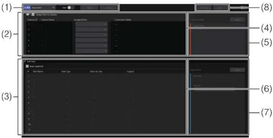
(1) Role set management area
Starts edition for [Select Role] and [Edit Role]. You can also select and apply role sets.
(2) [Assign Role to Camera] Configures role sets.
(3) [Edit Role] Configures roles.
(4) Camera list Displays the list of cameras and sets an [Assigned Role] to a [Camera ID].
(5) [Camera Details]
Configures camera details.
(6) [Role List]
Displays the list of roles and lets you set the [Roles to Link] for each role.
(7) [Role Details]
Configures details for a role.
(8) [Execute] / [Stop]
Starts or stops the selected role set.
2 Enable [Edit] in the role set management area.
Setup is enabled for [Assign Role to Camera] and [Edit Role].
3 Click the row of the [Role] number to set in the [Role List].
The selected row will be highlighted.
4 Select or enter each item in [Role Details] to create the role.
See "Role Details" (P. 35) for descriptions of each item.
Note
- Set the main camera's role [Role Type] to [Manual Control].
- Set the roles of Sub Cameras that will be linked to the Main Camera to [Automatic Control].
5 If [Role Type] in [Role Details] is [Automatic Control], select the [Roles to Link] in the [Role List].
In most cases, the role* with [Role Type] set to [Manual Control] is selected.
* Refers to the main camera.
6 Repeat steps 3 to 5 to create all required roles.
7 In the role set management area, click [Apply] to save the settings.
8 Disable [Edit].
Note
A main camera is required. Create a [Manual Control] role.
Setting a Role Set
The roles created in “Creating/Editing a Role” (P. 20) are assigned to a [Camera ID] and saved as a role set. Up to 50 role sets can be saved.
1 Select the [Edit Role Set] tab in the screen switching tabs.
The [Edit Role Set] screen will be displayed.
2 In the role set management area, select the role set number in [Role Set XX] and enable [Edit].
Setup is enabled for [Assign Role to Camera] and [Edit Role].
3 In the camera list, click the row of the [Camera ID] for the camera you want to configure.
The selected row will be highlighted.

(1) [Camera ID]
The camera ID is displayed.
(2) [Connection Status]
If a camera is set to [Camera ID], the camera or lens* connection status is displayed.
* For system cameras, the lens connection status is displayed.
| Connection status Description | |
| --- Not connected to MCO. | |
| Connected The camera or lens is connected. | |
| Standby* The camera is in standby. | |
| Not connectable The connection to the camera or lens has been lost. | |
| Not Configured No camera has been set to [Camera ID]. | |
| Authentication required* | Connected but requires authentication (cannot be authenticated using the set administrator name/password). |
* Displayed for cameras other than system cameras.

Note
- The procedure for setting a camera to a [Camera ID] is explained in “Connecting Main/Sub-Cameras” (P. 24).
- You can configure role sets even when the camera's status is not [Connected].
4 Enter the [Camera Name] in [Camera Details].
The [Camera Name] is set in the [Camera ID].
5 Select the [Assigned Role] from [Assign Cameras and Roles].
From the pre-created roles (P. 20), select the role to assign to the [Camera ID].

Note
- In MCO, cameras and roles are linked via the [Camera ID]. Here, roles are assigned to the [Camera ID].
- A main camera is required. Assign a [Manual Control] role to a [Camera ID].
6 Repeat steps 3 to 5 to configure all cameras to be used.
When setting up multiple role sets in succession, select a different role set in the role set management area and repeat steps 3 to 5.

Note
[Camera Name] is shared across all role sets. It cannot be changed per role set.
7 Click [Apply] in the role set management area to save the settings.
8 Turn off [Edit].
At the shooting site, set up the main camera, sub-camera, overhead camera, and iPhone to be used for shooting.
■ Overhead Camera Installation
- Two overhead cameras must be installed and connected to MCO. Configure the "shooting range" and "stage area" in advance. For details, refer to "Stage Settings" (P. 26).
• Install the cameras so that the "shooting range" fits within the fixed viewing angle. - Position each overhead camera so that the "shooting range" is captured as large as possible within the viewing angle. If the "shooting range" is too small relative to the overhead camera's angle, the tracking performance of the subject may decrease.
- Ensure that subjects do not overlap within the overhead camera's viewing angle.

Note
By installing the overhead camera above the subject, you can avoid subject overlap.
![graph TD A["Stage Area"] --> B["Overhead Camera"] A --> C["Camera 1"] A --> D["Camera 2"] A --> E["Camera 3"] F["Person 1"] --> G["Table"] H["Person 2"] --> G I["Person 3"] --> G G --> J["Left Panel"] G --> K["Right Panel"] style A fill:#f9f,stroke:#333 style F fill:#ccf,stroke:#333 style H fill:#cc…](/content/2026/08/1630012/images/69ac2de00d4f216fabfe6482d7d8222d5f86f76be325ea6e1c4dc42c71686b89.jpg)
■ Main Camera/Sub-Camera Installation
The number of main/sub-cameras that can be connected to MCO depends on the type of license in use.
| License Type Number of Cameras |
| Full License 1 main camera, 4 sub-cameras |
| Lite License 1 main camera, 3 sub-cameras |
Position the cameras so that each camera's subject is fully within the camera's angle of view.
■ iPhone Mounting for the Main Camera
If the main camera is a digital cinema camera, video camera, or a system camera, mount an iPhone with Multi-Camera Control installed onto the main camera. Place the iPhone in landscape orientation with its screen facing the camera operator, and mount it so that it is perpendicular to the camera's optical axis. This allows the iPhone to capture the movement of the camera's optical axis.
MCO obtains the pan/tilt position of the main camera via Multi-Camera Control.
Connect cameras and the Control Panel application to MCO. Connection settings are performed in the Control Panel application.
■ Connection Settings for the Control Panel Application
Connect the Control Panel application to MCO.
1 Start MCO (P. 17).
2 Select the [Connection Settings] tab in the screen switching tabs.
[System Connection Settings] is displayed.
3 Click [System Connection Settings] > [Edit].
The [System Connection Settings] will become editable.
4 Enter the required items for each field.
| Setting item Description |
| Connection Address Enter the IP address of the server that runs the Core application. |
| Port No. Enter the HTTP port number configured in the Core application. |
5 Click [Apply] to save the settings.
When connection to MCO is completed, the current MCO status is displayed in [Status] (P. 19).
■ Connecting a Main Camera/Sub-Camera
Connect the main and sub-cameras to MCO.
1 Select the [Connection Settings] tab in the screen switching tabs.
[Camera Settings] is displayed.
2 Select the row with the camera's [No.] in the list and click [Edit].
The [Advanced Camera Settings] screen appears.
3 After selecting [Device Type], enter each field under [Camera Connection Settings] and [Camera Installation Information], then click [Save].
For details on each field, refer to "Camera Settings / Overhead Camera Settings" > "Advanced Camera Settings" (P. 35).
4 In the [Camera Settings], select the [Camera ID].
Set a [Camera ID] to the camera. If a role is already assigned to the [Camera ID], the role will be linked to the camera.
5 Repeat steps 2 to 4 for each camera.
6 Check the status display of the connected cameras.
The connection status of connected cameras is displayed in the corresponding row in [Camera Settings].
| Item Description | |
| Connection Address*1 | Displays the camera's IP address. Configure it in the [Advanced Camera Settings] screen. |
| Connection Status [Camera or Lens*2 Connection Status / iPhone Connection Status] | Displays the connection status of the camera/lens*2/iPhone. |
| MAC Address*1 | Displays the camera's MAC address. |
| Model Name*1 | Displays the camera's model name. |
| Camera ID Selects the camera ID (Step 4). | |
| Device Type | Displays the camera's device type. Configure it in the [Advanced Camera Settings] screen. |
*1 When a system camera is used, [---] is displayed.
*2 For system cameras, the lens connection status is displayed.
Camera or Lens* / iPhone Connection Status
| Connection status Description | |
| --- Camera or Lens: Not connected to MCO. | iPhone: Not connected to MCO, or the camera's [Device Type] is set to [Remote Camera]. |
| Connected Connected to the camera or lens/iPhone. | |
| Standby* | The camera is in standby. |
| Not connectable Connection to the camera or lens/iPhone has been lost. | |
| Authentication required* | Connected but requires authentication (cannot be authenticated using the set administrator name/password). |
* Displayed for cameras other than system cameras.
Note
The iPhone connection status can only be confirmed in Multi-Camera Control when pan/tilt information is being sent. If sending is stopped, it will display [Not connectable].
■ Connecting an Overhead Camera
Connect overhead cameras to MCO. Select the [Connection Settings] tab from the screen switching tabs. [Overhead Camera Settings] will be displayed.
The setup procedure is the same as steps 2 to 6 in "Connecting a Main Camera/Sub-Camera" (P. 24).

Note
Since the overhead camera is a remote camera, [Device Type] is not selected. Also, because no role is assigned, [Camera ID] is not selected.
Before shooting with MCO, you need to configure the stage settings. The stage settings include configuring the stage area, setting up tracking exclusion areas, and measuring and registering the camera position.
Areas/Markers Used for Stage Settings

(1) Shooting range
The shooting range for MCO. The shooting range is defined as the area within which the entire bodies of all subjects, when moving within the stage area, are fully captured within the viewing angle of two overhead cameras.
(2) [Stage Area]
The area within the shooting range where the subject moves.
(3)-(7) Markers A/B/C/D/E
Markers required for measuring the camera position. Position the markers so they are centered in the viewing angle of all cameras (main camera, sub-camera, and overhead cameras).
(8) [Tracking Exclusion Area]
An area in which, during tracking shoots with MCO, tracking is paused, and while tracking is paused, no search or selection of a tracking target is performed.
■ [Stage Settings] Tab Screen

(1) [Apply]
Applies the stage settings from the Control Panel application to the MCO.
(2) [Get Latest Settings]
Updates the Control Panel application with the stage settings currently applied to the MCO.
(3) [Camera Position Measurement]
Displays the [Camera Position Measurement] screen.
(4) [Stage Area]
Configures the stage area.
(5) [Tracking Exclusion Area]
Configures the tracking exclusion area.
(6) Area/Camera/Marker display area
Displays the configured areas, cameras, and markers in an overhead view.
■ Stage Area Setup
Set up the stage area. Measure the actual width and depth of the stage area, as well as the relative distance from Marker A (reference marker), and input these values into the Control Panel application.
Open the [Stage Settings] screen from the screen switching tabs (P. 19) in the Control Panel application.
1 Measure the [Width (m)] and [Depth (m)] values of the stage area and enter them in [Stage Area].
- The recommended size for the stage area differs depending on the license type.
![CANON BU-51H - Measure the [Width (m)] and [Depth (m)] values of the stage area and enter them in [Stage Area]. - 1](/content/2026/08/1630012/images/45f6a1ec12687324f18d4530f2f3b13ae42ae7a17fc3b18f7ff48f259fbf0e0c.jpg) |
^ Under certain camera installation conditions, performance may be reduced.
- By setting the stage area slightly larger than the actual range in which the subject can move, you can reduce the risk of the subject not being detected at the edges of the area.
2 Place Markers A / B / C / D / E.
The greater the distance between markers, the higher the accuracy of camera control. A distance of at least 2 m (6.6 ft.) is recommended.
- Position the 5 markers so they are centered* in the viewing angle of all cameras (main, sub and overhead cameras).
- Place markers A, B and C on the floor of the stage area.
- Markers A and B should be placed parallel to the horizontal direction of the stage area and at least 1 m (3.3 ft.) apart from each other. In this case, marker A is placed on the side of stage right, and marker B on the side of stage left.
- Marker C should be placed at least 1 m (3.3 ft.) away from A and B in the front-back direction.
- Place Markers D and E at a height of at least 1 m (3.3 ft.) above the floor of the stage area.
- Markers D and E should be placed at least 1 m (3.3 ft.) away from A and B in the front-back direction, and at least 1 m (3.3 ft.) apart from each other.
* When measuring the camera position, you must adjust so that each marker is at the center of the viewing angle at the camera's maximum zoom.
Note
• Each marker is used as a visual reference to ensure all cameras capture the same field of view during "Measure Camera Position" (P. 30).
- Place markers that are no larger than 1 cm (0.39 in.). If the markers are too large, measurement precision may decrease, affecting camera-control accuracy.
- Marker A serves as the reference marker and is used as the baseline for measuring distances during stage setup.
- If the camera positions are changed, you will need to use the markers again to perform camera position measurement and connection setup for Multi-Camera Control (P. 29). To make repositioning easier, it is recommended to mark the positions with tape or use fixed reference points such as walls.
3 Measure the relative position of the stage area from Marker A and enter it in [Stage Area].
- The relative position of the stage area is determined by measuring the distance between the vertex at the back side of stage right and Marker A.
- When viewing the stage area from the camera side, if the stage area is to the left of Marker A in the horizontal direction or above Marker A in the vertical direction, input the distance as a negative value.

- Enter the measured distances into the fields [Offset from A (Horizontal) (m)] and [Offset from A (Vertical) (m)].
4 Check that the 5 markers are centered in the viewing angle of all cameras (main, sub and overhead cameras). If a camera does not cover them, reposition the markers or the camera.
5 Click [Apply] to apply the settings to MCO.
■ Set the Tracking Exclusion Area
You can optionally set up tracking exclusion areas. This is useful in situations such as when there are posters with people in the camera's field of view. By setting exclusion areas, the system can more accurately detect the intended subject. Up to four exclusion areas can be set. The setup procedure is the same as for the stage area (P. 27).
1 Click one of the [Tracking Exclusion Area] areas.
The input fields for the selected area will be displayed.
2 Select [Rectangle].
3 Measure the [Width (m)] and [Depth (m)] values of the tracking exclusion area and enter them in [Tracking Exclusion Area].
4 Measure the relative position of the tracking exclusion area from Marker A and enter it [Tracking Exclusion Area].
- The method for measuring relative position is the same as in "Stage Area Setup" (P. 28).
- Enter the measured distances into the fields [Offset from A (Horizontal) (m)] and [Offset from A (Vertical) (m)].
5 Repeat steps 1 to 4 as necessary.
6 Click [Apply] to apply the settings to MCO
■ Multi-Camera Control Connection Setup
Perform the connection setup for Multi-Camera Control when the main camera is a digital cinema camera, a video camera, or a system camera.

Note
You must install the iPhone onto the main camera in advance. Complete the procedure described in "iPhone Mounting for the Main Camera" (P. 23) beforehand.
1 Configure the iPhone's Ethernet settings and connect it to the server running the Core application.
2 Start Multi-Camera Control on the iPhone.
3 Register the sub-cameras in Multi-Camera Control.
You can check the live feed from the sub-cameras on the iPhone. Up to 4 sub-cameras can be registered.
4 Select MCO mode in Multi-Camera Control.
5 Enter the IP address/FreeD port number of the server running the Core application.
6 With the main camera (with the mounted iPhone) facing the reference marker*, start sending data.
This will start pan/tilt information output from the iPhone to MCO.
* Refers to Marker A placed during "Stage Area Setup" (P. 27).
7 Use the Control Panel application to measure the camera position (P. 30).
8 With the main camera (with the mounted iPhone) facing directly forward in the shooting direction, tap the onscreen button to set the displayed values to zero.
The forward direction will serve as the reference for the values displayed in Multi-Camera Control.
You can use this to confirm the direction in which the camera moves.

Note
- If the position of the main camera or iPhone is changed, you will need to measure the camera position again. Please follow steps 4 through 8 again.
- If you switch to the home screen or another application while Multi-Camera Control is transmitting, or if you resume after stopping transmission, make sure the reference marker is facing the same way as in step 6 before resuming.
■ Measure Camera Position
To enable automatic camera control by MCO, measure the camera positions in advance. For all cameras (main camera, sub-camera, and overhead camera), register each of the five markers so that they are within the camera's viewing angle, and then perform the camera-position measurements.

Note
If the camera positions are changed after measurement, you must remeasure the camera positions. Otherwise, proper shooting may not be possible.
1 Click [Camera Position Measurement].
The [Camera Position Measurement] screen appears.

(1) [Select Camera to Control]
Displays a list of connected main, sub, and overhead cameras, along with the number of registered markers.
(2) [Distance Between Markers A and B (m)]
Enter the distance between Marker A and Marker B.
(3) Camera Video Display area
Displays the live feed from the selected camera. Use buttons/sliders to pan, tilt, and zoom.
(4) [Register Marker Positions]
Register the positions of the markers.
(5) [Measure]
Measure the camera position.
2 Verify that all cameras (main/overhead/sub-cameras) are connected to MCO.
Connected cameras are displayed in [Select Camera to Control] > [Camera List] and [Overhead Camera List]. Refer to "Connecting a Main Camera/Sub-Camera" (P. 24) and "Connecting an Overhead Camera" (P. 25).
3 Measure the distance from Marker A to Marker B (set in "Stage Area Setup", P. 27) and enter it in [Distance Between Markers A and B (m)].
4 In [Select Camera to Control], choose the camera number for which you want to register marker positions
- In case of remote cameras or video cameras, the video feed from the selected camera will be displayed in the camera video display area.
5 Adjust the camera's pan, tilt, and zoom so that Marker A is centered in the viewing angle at the camera's maximum zoom level.
- Adjust so that the + mark in the center of the video feed aligns with the center of Marker A.
- For remote cameras, you can also adjust pan, tilt, and zoom using the sliders and buttons in the camera video display area.
Note
For remote cameras, clicking any point in the camera video display area will automatically pan/tilt the camera to center on that point.
6 Click [Register] for A in [Register Marker Positions] to save the setting.
Note
For remote cameras, clicking [Browse] will move the camera's pan and tilt positions to the registered position, which can be confirmed in the camera video display area.
7 Repeat steps 5 and 6 for markers B, C, D, and E.
8 Repeat steps 4 to 7 for all cameras in [Select Camera to Control].
9 Click [Measure] to perform camera position measurement.
Note
If [Measure] is unavailable, it is possible that the registration of all markers for all cameras has not been completed. Check [Total Registrations] under [Select Camera to Control].
10 In [Select Camera to Control], select an overhead camera, then adjust the camera's pan, tilt, and zoom so that the entire shooting range fits within the viewing angle.
Adjust so the "shooting range" is captured as large as possible within the overhead camera's viewing angle.
Note
Perform this adjustment for each of the two overhead cameras.
11 Close the [Camera Position Measurement] screen.
Start/Stop Shooting
When a role set is started in the Control Panel application, MCO begins shooting.

Note
If the main camera is a digital cinema camera, video camera, or system camera, keep the camera tilt within -70° to +70° from vertical when shooting.
1 Select the [Edit Role Set] tab from the screen switching tabs.

(1) Role Set Management area
You can select and apply role sets.
(2) [Execute] / [Stop]
Executes/stops the selected role set.
(3) [Tally Lock]
When [Tally Lock] is turned on, the following operations are deferred for cameras with the tally light on. This feature is used, for example, to prevent disruption in the sub-camera's footage when the framing of the main camera is changed.
![CANON BU-51H - [Tally Lock] - 1](/content/2026/08/1630012/images/51cbd290e5bbd2f2af371b0eacd5016bb61b56f5ec33c11aa12c81c5e54108c0.jpg)
Note
To use the Tally Lock function, you must configure the switcher so that the tally lamp of the corresponding remote camera lights up when video is switched. Be sure to set this up in advance on both the switcher and the remote camera.
| User operation Operation specifications | |
| Role set switching Operation is deferred. When the tally | light is off or [Tally Lock] is turned off, the operation is restarted. |
| System operation Operation specifications | |
| Operating [Linked to Size] when the camera's [Role Type] is set to [Automatic Control] (P. 35) | The state before the tally light turns on, or before [Tally Lock] is enabled, is maintained. Operation resumes when the tally light is turned off or [Tally Lock] is disabled. |
2 Select [Role Set XX] in the Role Set Management area and click [Execute].
If you change [Role Set XX] and click [Execute] again, the role set will switch. You can also switch role sets as explained in “Switching Role Sets” (P. 34).
![CANON BU-51H - Select [Role Set XX] in the Role Set Management area and click [Execute]. - 1](/content/2026/08/1630012/images/955ffc4a9ee3e3bbd88c5afbde13046d8fd86151896a124f64c45c546726fd7a.jpg)
Note
- You cannot start shooting while editing a role set. Make sure that [Edit] in the Role Set Management area is turned off.
- You can change role sets and role settings even during shooting. Any edits made during shooting will be applied immediately when you click [Apply] in the Role Set Management area. For editing instructions, refer to "Role Setup" (P. 20).
- While a role set is running, clicking [Execute] will execute the specified role set again with the current shooting conditions.
3 Check the operation status in [Status] (P. 19).
4 To end shooting, click [Stop].
During shooting, you can check the footage from each camera and their assigned roles. You can also switch role sets during shooting. This operation is performed using the Control Panel application.
■ Checking the Shooting Status and Footage
You can check the camera footage, assigned roles, shooting status, and tally output status.
1 Select the [Monitoring] tab on the screen switching tabs.
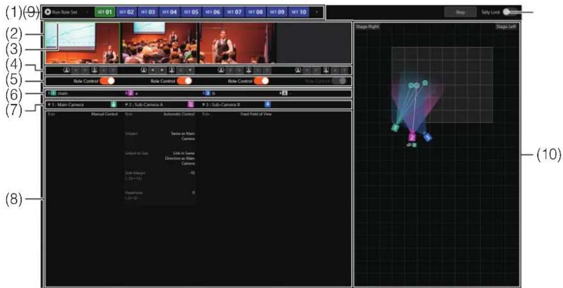
(1) [Run Role Set] buttons
Selects the role set corresponding to the clicked number and immediately switches to that role set.
(2) Camera video display area
Displays the camera's video.
(3) Tally lamp display
Shows the camera's tally lamp status according to the color of the frame.
| Tally Lamp Status Frame Color | |
| PGM Red | |
| PVW Green | |
| PGM+PVW Amber | |
(4) Framing movement buttons
Click to move the camera angle in the direction of each arrow. Operable when [Role Type] is set to [Automatic Control].
(5) [Role Control]
Toggles role control on/off.
(6) Camera name display
Displays the [Camera Name].
(7) Role name display
Displays the [Role Name] assigned to the camera.
(8) Role Settings Display area
Displays role settings.
(9) [Tally Lock]
When [Tally Lock] is switched on, control of cameras with active tally lights is deferred (P. 32).
(10) Shooting Status Display area
Displays an overhead view showing the shooting status. Indicates the camera orientation, role, and subject position, and operates in sync with the shooting status.
2 Check the footage on the camera video display area.
Video is not displayed for system cameras.
Note
- In sub-cameras or overhead cameras, the subject (person) may not be detected under the following conditions:
- The person appears extremely small or extremely large in the frame, or is very dark or very bright.
- The person is facing sideways or diagonally, or is upside down.
- When shooting a person from a high or low perspective, either from below or above.
- Part of the person is obscured (including sunglasses, hats, masks).
- People are clustered closely together.
- The person's appearance blends into the background.
- In addition to the conditions listed above, the following conditions may also prevent successful tracking of the subject:
- When the person is moving quickly.
- When people pass by or overlap with each other.
The icon in the camera video display area represents the current communication status with the camera.
| Icon Status | |
 | Standby:Displayed when the camera's [Device Type] is set to an option other than [System Camera]. |
 | Disconnected:Displayed when the camera's [Device Type] is set to an option other than [System Camera].Clicking it will attempt to reconnect with the camera. |
 | Transitioning to standby, returning from standby, or attempting to connect:Displayed when the camera's [Device Type] is set to an option other than [System Camera]. |
 | Cannot obtain video from the registered camera type:Displayed when the camera's [Device Type] is set to [System Camera]. |
3 Check the shooting status display area.
The stage area, tracking exclusion areas, subjects, each camera, and the shooting direction/target of each camera are displayed.
■ Switching Role Sets
Switch role sets during shooting.
1 Select the [Monitoring] tab from the screen switch tabs.
The [Run Role Set] buttons will be displayed.
2 Click the [Run Role Set] button that corresponds to the number of the role set you want to switch to.
- The role set configured in the [Edit Role Set] tab will be executed.
- Clicking the [<] or [>] buttons in the role set execution area switches the display to the previous or next 10 role set numbers. The currently executing role set will not be changed.
Note
While a role set is running, if you click the [Run Role Set] button with the same number, the role set will be executed again with the current shooting conditions.
Control Panel Application Menu Options
Connection Settings
■ Camera Settings / Overhead Camera Settings > Advanced Camera Settings
| Item Setting item | Description | |
| Device Type Specifies the | camera's device type. Except for [System Camera], used when the camera is a Canon model. | |
| Camera Connection Settings | Configures the camera's connection settings. Available when [Device Type] is set to [Remote Camera], [CINEMA EOS], or [Video Camera]. | |
| Connection Address Enters | the camera's IP address. | |
| Administrator Name Enters | the user name/password of the camera administrator. | |
| Password | ||
| Port No. Enter the camera's | communication port number. | |
| Camera Installation Information | Position Relative to Reference Marker | Displays the camera's 3D position measured in [Stage Settings]. If not measured, this field will be blank. |
| Width (X) (cm) Displays the | camera's position relative to the measured reference marker. | |
| Depth (Y) (cm) Displays the | camera's position relative to the measured reference marker. | |
| Height (Z) (cm) | Displays the camera's position relative to the measured reference marker. |
Edit Role Set
Role Details
| Setting item Setting | values/Description |
| Role Name Enters the role name. | |
| Role Type [Manual Control] | Main camera role. The camera operator manually controls the camera.[Automatic Control]Sub-camera role. MCO automatically controls the camera based on the configured settings.[Fixed Field of View]The camera's pan, tilt, and zoom positions are set to fixed values. |
| Subject Switching Sensitivity | Can be set when the role type is set to [Manual Control].The higher the value, the more likely MCO is to switch the main camera's target subject. |
| Linked Size Range (Max) C | Can be set when the role type is set to [Manual Control]. |
| Linked Size Range (Min) | When the sub camera's [Linked to Size] is set to [Link in Same Direction as Main Camera] or [Link in Opposite Direction to Main Camera], you can specify the maximum/minimum range for the subject size in the main camera.Moving the slider to the right results in a framing where the subject's face appears larger; moving it to the left results in a framing that shows the whole body.Also refer to the sub-camera's [Linked Size Range] (P. 38). |
| Subject Can be set when the | the role type is set to [Automatic Control].[Same as Main Camera]Tracks and shoots the same subject as the main camera. Automatic camera control is not performed when there is no subject for the main camera.[Stage Left Edge (different from Main Camera)][Stage Right Edge (different from Main Camera)]Tracks and shoots the subject positioned furthest to stage left (or right) among those outside the main camera's field of view. If the only subjects in the shooting range are those within the main camera's field of view, the same subject will be shot.[Everyone]Captures all subjects within the shooting range, keeping them within the frame.[Specify Reference Position / Order]Among the subjects in the shooting range, starting from the reference subject (position), tracks and shoots the neighboring subjects in the specified order. |
| Reference Position & Orientation | Can be set when the role type is set to [Automatic Control] and [Subject] is set to [Specify Reference Position / Order].You can specify the direction in which to count from the reference position and define the sequence number to determine the target subject. If the specified subject in the given order does not exist, the subject located at the furthest end in the specified direction will be captured.[From Stage Left Edge]Using the subject closest to stage left within the shooting range as the reference, count the [Order from Reference Position] toward stage right.[Stage Left from Main Camera Subject]Using the subject in the main camera's frame as the reference, count the [Order from Reference Position] toward stage left.[Stage Right from Main Camera Subject]Using the subject in the main camera's frame as the reference, count the [Order from Reference Position] toward stage right.[From Stage Right Edge]Using the subject closest to stage right within the shooting range as the reference, count the [Order from Reference Position] toward stage left. |
| Order from Reference Position | |
| Exclude Main Camera Subject | Can be set when the role type is set to [Automatic Control] and [Subject] is [Specify Reference Position / Order].When enabled, subjects within the main camera's frame are excluded from the [Order from Reference Position]. They are skipped, and the sequence continues with the next adjacent subject in the specified direction.When enabled, and [From Stage Left Edge] is selectedStage Right      Stage LeftMain Camera Subject Stage LeftMain Camera Subject |
When disabled, and [From Stage Left Edge] is selectedStage Right      Stage LeftMain Camera Subject Stage LeftMain Camera Subject | |
When enabled, and [Stage Left from Main Camera Subject] is selectedStage Right      Stage LeftMain Camera Subject Stage LeftMain Camera Subject | |
When disabled, and [Stage Left from Main Camera Subject] is selectedStage Right      Stage LeftMain Camera Subject Stage LeftMain Camera Subject | |
| Linked to Size | Can be set when the role type is set to [Automatic Control] and [Subject] is set to an option other than [Everyone].[Link in Same Direction as Main Camera]Follows the main camera's zoom movement in the same direction.[Link in Opposite Direction to Main Camera]Follows the main camera's zoom movement in the opposite direction.[Specify Subject Size]Controls zoom so that the shooting target matches the size specified in [Subject Size]. Does not link zoom to the main camera. |
| Linked Size Range (Max) | Can be set when the role type is set to [Automatic Control] and [Linked to Size] is set to [Link in Same Direction as Main Camera] or [Link in Opposite Direction to Main Camera]. |
| Linked Size Range (Min) | The sub-camera synchronizes the subject size with the main camera, within the range defined by [Linked Size Range]. Moving the slider to the right results in a framing where the subject's face appears larger; moving it to the left results in a framing that shows the whole body. Main/Sub-camera subject size for [Link in Same Direction as Main Camera] ·When [Linked Size Range] is the same on the main and sub-camera: Main camera  Sub-camera ·When [Linked Size Range] is different on the main and sub-camera (example 1): Main camera Sub-camera ·When [Linked Size Range] is different on the main and sub-camera (example 1): Main camera 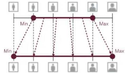 Sub-camera ·When [Linked Size Range] is different on the main and sub-camera (example 2): Main camera Sub-camera ·When [Linked Size Range] is different on the main and sub-camera (example 2): Main camera  Sub-camera Main/Sub-camera subject size for [Link in Opposite Direction to Main Camera] ·When [Linked Size Range] is different on the main and sub-camera: Main camera Sub-camera Main/Sub-camera subject size for [Link in Opposite Direction to Main Camera] ·When [Linked Size Range] is different on the main and sub-camera: Main camera  Sub-camera Sub-camera |
| Subject Size | Can be set when the role type is set to [Automatic Control] and [Subject] is set to [Everyone], or [Linked to Size] is set to [Specify Subject Size].Moving the slider to the right results in a framing where the subject's face appears larger; moving it to the left results in a framing that shows the whole body. When [Subject] is set to [Everyone], the framing is adjusted so that everyone is visible. |
| Framing Adjustment Method (Horizontal) | Can be set when the role type is set to [Automatic Control] and [Subject] is set to an option other than [Everyone].[Manual]Sets the left and right margins around the subject's face using the [Side Margin] setting.[Auto (Direction of Gaze)]Automatically adjusts the horizontal composition to leave space in the direction of the subject's gaze. May not function if the target's face is not detected. |
| Side Margin Can be set when the role type is set to [Automatic Control] and [Framing Adjustment Method (Horizontal)] is set to [Manual].Sets the left and right margins around the subject's face. Moving the slider to the right increases the margin on the right side of the face, while moving it to the left increases the margin on the left side. | |
| Directional Sensitivity | Can be set when the role type is set to [Automatic Control] and [Framing Adjustment Method (Horizontal)] is set to [Auto (Direction of Gaze)].Sets the sensitivity for framing adjustments. The larger the value, the more frequently adjustments are made. |
| Gaze Line Margin Can be set when the role type is set to [Automatic Control] and [Framing Adjustment Method (Horizontal)] is set to [Auto (Direction of Gaze)].The larger the value, the more space is left in the direction of the subject's gaze. | |
| When Facing Forward Can be set when the role type is set to [Automatic Control] and [Framing Adjustment Method (Horizontal)] is set to [Auto (Direction of Gaze)].Sets the operation performed when the subject's gaze faces forward. Choose either [Return to Center] or [Maintain]. | |
| Headroom Can be set when the role type is set to [Automatic Control].Sets the amount of space above the subject's head. Move the slider to the right to increase the margin, or move it to the left to decrease it. | |
| Tracking Sensitivity Configurable when the role type is [Automatic Control].Adjusts the sensitivity for subject tracking. Higher values result in quicker and more responsive tracking. | |
| Pan (°) Can be set when the role type is set to [Fixed Field of View].Tilt (°)Sets the camera's pan, tilt, and zoom values. | |
| Zoom (Horizontal Field of View (°)) | |
Keyboard Shortcuts
The Control Panel application can be operated using the keyboard. The functions that can be controlled via the keyboard and their assigned keys are as follows:
| Function Key Condition | ||
| Start Role Set (Role Sets 1–10) 0–9* | 1 | When the [Monitoring] tab is open |
| Ctrl + Alt + 0–9*1 | Anytime | |
| Start Role Set (Role Sets 11–20) Ctrl + Alt + Windows + 0–9*2 | Windows + 0–9*2 | Anytime |
| Stop Role Set Q When the [Monitoring] tab is open | ||
| Toggle Tally Lock On/Off T When the [Monitoring] tab is open | ||
| Navigate [Monitoring] Pages | ← or → | When the [Monitoring] tab is open |
1 Keys 0, 1–9, or NumPad0, NumPad 1–9 correspond to Role Set numbers 10, 1–9 respectively.
*2 Keys 0, 1–9 correspond to Role Set numbers 20, 11–19 respectively.
While a role set is running, pressing the key that executes the current role set will execute it again with the current shooting conditions.
Exporting and Importing Settings
Exporting Settings
Core Application
Export the settings of the Core application. From the [Maintenance] menu, click [Export]. Follow the dialog prompts to save the file.
■ Control Panel Application
Exports each setting. Open the [Maintenance] tab screen. Click [Export] to display the [Export] dialog. Select the items to export, and then click [Export]. Follow the dialog prompts to save the file.
Importing Settings
Core Application
Imports the settings of the Core application. From the [Maintenance] menu, click [Import]. Select the file containing the settings you want to import, and the settings will be applied. Settings can only be imported when the MCO status is [Stopped].
■ Control Panel Application
Exports each setting. Open the [Maintenance] tab screen and click [Import]. When you select the file containing the settings you want to import, the [Import] dialog will be displayed. Select the items to import, then click [Import]; the settings will be applied.
Troubleshooting
Before contacting the retailer from where the product was purchased or a Canon sales representative, check the following items.

Note
For details on troubleshooting for cameras, controllers, or switchers, refer to their respective manuals.
Core Application
| Problem Solution | |
| Cannot start MCO. • No valid license applied. Apply a | icense.• The license has expired. Renew the license.• Verify that the server is configured correctly (P. 17).[7x8T] NoteIf DHCP is used, the IP address may change. It is recommended to operate MCO with a fixed IP address. |
| Cannot start the application. | • If the Core application is already running, it cannot be launched a second time. |
■ Control Panel Application
| Problem Solution | |
| Cannot connect to MCO. • Check that MCO is running | (P. 17).• Check that the [System Connection Settings] parameters are configured correctly (P. 24).• Check that [Connection Address] is not duplicated with other devices or cameras.• Check whether the Windows Firewall is enabled for either the Core application, the Control Panel application, or both (P. 16, P. 18). |
| Cannot start the application. | • If the Control Panel application is already running, it cannot be launched a second time. |
| Cannot connect to the camera. • Check that the camera | is powered on.• Check that [Camera Connection Settings] parameters are configured correctly (P. 24).• Check that [Connection Address] is not duplicated with other devices or cameras. |
| Camera video not displayed. • Check the network connection status. | • Verify that both the camera and the computer running this application are properly connected to the network.• Add the camera and this application to the exclusion/allow list of your security software.• The camera that is not supported for video display in this application. |
| The camera cannot be operated. | • The camera is not compatible with remote control or operation via this application. |
| The sub-camera does not track the subject. | Verify that the stage settings and the camera position measurement are correct (P. 26).Check that the overhead camera is installed correctly (P. 23).Check that the entire shooting range fits within the viewing angle of the overhead camera (P. 31).Confirm the following if you are using a digital cinema camera, video camera, or a system camera:- Check that the iPhone is properly connected to the network (P. 25).- When starting transmission with Multi-Camera Control, make sure the main camera is pointing at the reference marker. If sending begins without proper alignment, stop the transmission and reconfigure the Multi-Camera Control connection settings (P. 29).- Check if you switched to the home screen or another application during Multi-Camera Control transmission. If you did, start transmission again following the correct procedure (P. 29).If using a system camera, confirm that the lens is properly connected to the network (P. 25).Non-human objects may occasionally be misdetected as people. In that case, remove the misdetected object from the scene or set the area containing it as a tracking exclusion area.Check that Tally Lock is not enabled (P. 32).Check that the conditions do not fall under those where the subject cannot be detected or tracked (P. 34).For Full license users, ensure that the Auto-Tracking Application for the sub-camera is running and that the auto-tracking shooting settings have been initialized. If MCO is already running, stop it once before operating the Auto-Tracking Application (P. 17). |
| The [Stage Settings] tab is grayed out and cannot be opened. | Check that the Control Panel application is connected to MCO. Verify the connection status (P. 24). |
| Setting items are grayed out, selection/input is not possible. | When editing a role, enable [Edit] on (P. 20).Some setting items may be grayed out depending on conditions such as the MCO connection status or when certain functions are being executed. |
If an error message appears on the screen, proceed as suggested below.
Core Application
| Message Solution | |
| GPU cannot be used. • The Core application was unable to use the GPU. Check whether Windows recognizes the GPU. Also, verify that the computer has been properly prepared in advance (P. 16). | |
| Uninstall Lite license and apply Full license. | • You attempted to apply a Full license while a Lite license is still active. Confirm whether this is acceptable, then either proceed with applying the Full license or cancel. |
| Failed to start MCO Control Panel. Please check installation status. | • The Control Panel application could not be started. When starting the Control Panel application from the Core application, it must be installed on the same computer as the Core application. |
| Failed to apply Trial license. | • The Trial license has already expired. To continue using the software, apply a paid license. |
| Failed to save configuration file. | • Insufficient free space at the destination. Delete unnecessary files to free up space. |
| The selected license file contains a perpetual license. | • Choose whether to apply only perpetual licenses or to exclude perpetual licenses. |
| A perpetual license is already applied. | • A computer with a perpetual license applied cannot accept a time-limited license. |
| Mixed license types detected. | • A mix of Full and Lite licenses has been detected. Please choose either license type to proceed. |
| Failed to install license. | • There is not enough free space at the destination for the license file. Delete unnecessary files to free up space.• A license file can only be applied on the computer that generated the request data. Verify that the computer you are applying it on is the same one that retrieved the request data. |
| License downgrade is not allowed. | • A computer with a Full license already applied cannot accept a Lite license. If you want to downgrade, uninstall the Full license first, then apply the Lite license. |
| Duplicate license file detected. | • Check for duplicate license files and select the correct license file. |
| Failed to obtain request data. • Insufficient free space at the destination. Delete unnecessary files to free up space.• You do not have permission to access the save destination. Check your access permission. | |
■ Control Panel Application
| Message Solution | |
| There are differences between Control Panel and System settings.Apply: Apply Control Panel settingsRetrieve: Retrieve System settings | After connecting to MCO, a discrepancy between MCO and Control Panel application settings was detected. Select [Apply] or [Retrieve]. |
| Stop Role Sel to perform camera position measurement? | Opened the [Camera Position Measurement] screen while a role set was running. Click [OK] to stop the role set, or [Cancel]. |
| Measurement failed. Check the camera connection status, and retry measurement. | When measuring the camera position, the camera was disconnected. Check the camera connection (P. 24). |
| Measurement failed. Register at least three cameras, and retry measurement. | When measuring camera position, three or more cameras must be connected. Check the camera connections (P. 24). |
| Measurement failed. There is a problem with marker or camera placement. Follow the instructions at the top of the screen to review the placement, and retry measurement. | Adjust the placement of the camera or the markers (P. 23, P. 27). |
| Please apply the current settings or retrieve the latest settings. | Attempted to switch the screen tab before completing the stage settings. Select either [Apply] or [Get Latest Settings] for the stage settings. |
| This destination address is already registered. | Attempted to register a camera using an already registered IP address. Check the IP address. |
| System connection was lost. Unsaved settings will be discarded. After reconnecting, please reconfigure your settings. | Disconnected from MCO while the [Stage Settings] tab screen was displayed. Check the connection. |
| Please apply or cancel unsaved changes. | The role/role set settings have not been saved. Apply the settings. |
| Discard unsaved changes? | You clicked [Cancel] in the role set management area. Click [OK] to discard the changes or [Cancel] to review them. |
| Save unsaved changes? | The role/role set settings have not been saved. Click [OK] to save or [Cancel] to verify the changes. |
| The license has expired.Please renew the license. | The license had expired at the time of connection to the Core application. Renew the license. |
| The license will expire soon.Please renew the license. | After connecting to the Core application, the license was found to expire in less than two weeks. Renew the license. |
Trademarks
- Microsoft and Windows are trademarks or registered trademarks of Microsoft Corporation in the United States and other countries.
- Windows is legally recognized as the Microsoft Windows Operating System.
- App Store and iPhone are trademarks of Apple Inc., registered in the U.S. and other countries.
- The terms HDMI, HDMI High-Definition Multimedia Interface, HDMI Trade dress and the HDMI Logos are trademarks or registered trademarks of HDMI Licensing Administrator, Inc.
- U S B T y and USB-C are trademarks of USB Implementers Forum.
- All other company or product names used in this document are trademarks or registered trademarks of their respective holders.



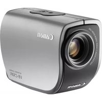
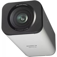
- MULTI-CAMERA ORCHESTRATION SYSTEM
- USER MANUAL
- TABLE OF CONTENTS
- INTRODUCTION
- GETTING STARTED
- MCO WORKFLOW
- APPLICATION SETUP
- SHOOTING PREPARATIONS
- BEFORE USE
- MULTI-CAMERA ORCHESTRATION SYSTEM OVERVIEW
- MULTI-CAMERA ORCHESTRATION CORE OVERVIEW
- MULTI-CAMERA ORCHESTRATION CONTROL PANEL OVERVIEW
- NOTES
- ILLUSTRATIONS AND SCREENSHOTS
- CONVENTIONS USED IN THIS MANUAL
- LICENSING FOR THE MULTI-CAMERA ORCHESTRATION SYSTEM
- RESTRICTIONS
- ROLES
- ROLE SET CONFIGURATION EXAMPLE 1: SHOOTING A DIFFERENT SUBJECT WITH THE SAME FRAMING AS THE MAIN CAMERA
- ROLE SET CONFIGURATION EXAMPLE 2: SHOOTING SUBJECTS DIFFERENT FROM THE MAIN CAMERA AND GROUP SHOTS
- ROLE SET CONFIGURATION EXAMPLE 3: SHOOTING SUBJECTS DIFFERENT FROM THE MAIN CAMERA WITH A DIFFERENT FRAMING
- NOTE
- SYSTEM CONFIGURATION EXAMPLE 1: REMOTE CAMERA AS MAIN CAMERA
- SYSTEM CONFIGURATION EXAMPLE 2: DIGITAL CINEMA CAMERA/VIDEO CAMERA AS MAIN CAMERA
- SYSTEM CONFIGURATION EXAMPLE 3: SYSTEM CAMERA AS MAIN CAMERA
- APPLICATION SETUP (P. 16)
- SHOOTING PREPARATIONS (P. 20)
- OPERATION (P. 32)
- COMPUTER PREPARATIONS
- STARTING THE CORE APPLICATION
- CORE APPLICATION MAIN SCREEN
- LICENSE STATUS DISPLAY AREA
- [SERVER CONFIGURATION]
- STARTING MCO
- INPUT EACH [SERVER CONFIGURATION] SETTING ITEM
- IMPORTANT
- CLICK [START]
- LICENSE AUTHENTICATION
- AUTHENTICATION USING A TRIAL LICENSE
- AUTHENTICATION USING A PAID LICENSE
- CONTROL PANEL APPLICATION
- STARTING THE CONTROL PANEL APPLICATION
- CONTROL PANEL APPLICATION MAIN SCREEN
- SCREEN SWITCHING TABS
- [STATUS]
- SETTINGS AREA
- MULTI-CAMERA CONTROL
- INSTALLING MULTI-CAMERA CONTROL
- ROLE SETUP
- CREATING/EDITING A ROLE
- SELECT THE [EDIT ROLE SET] TAB IN THE SCREEN SWITCHING TABS
- ENABLE [EDIT] IN THE ROLE SET MANAGEMENT AREA
- SETTING A ROLE SET
- OVERHEAD CAMERA INSTALLATION
- MAIN CAMERA/SUB-CAMERA INSTALLATION
- IPHONE MOUNTING FOR THE MAIN CAMERA
- CONNECTION SETTINGS FOR THE CONTROL PANEL APPLICATION
- CONNECTING A MAIN CAMERA/SUB-CAMERA
- CHECK THE STATUS DISPLAY OF THE CONNECTED CAMERAS
- CONNECTING AN OVERHEAD CAMERA
- AREAS/MARKERS USED FOR STAGE SETTINGS
- SHOOTING RANGE
- [STAGE AREA]
- (3)-(7) MARKERS A/B/C/D/E
- [TRACKING EXCLUSION AREA]
- [STAGE SETTINGS] TAB SCREEN
- [APPLY]
- [GET LATEST SETTINGS]
- [CAMERA POSITION MEASUREMENT]
- AREA/CAMERA/MARKER DISPLAY AREA
- STAGE AREA SETUP
- MEASURE THE [WIDTH (M)] AND [DEPTH (M)] VALUES OF THE STAGE AREA AND ENTER THEM IN [STAGE AREA]
- PLACE MARKERS A / B / C / D / E
- MEASURE THE RELATIVE POSITION OF THE STAGE AREA FROM MARKER A AND ENTER IT IN [STAGE AREA]
- CHECK THAT THE 5 MARKERS ARE CENTERED IN THE VIEWING ANGLE OF ALL CAMERAS (MAIN, SUB AND OVERHEAD CAMERAS). IF A CAMERA DOES NOT COVER THEM, REPOSITION THE MARKERS OR THE CAMERA
- CLICK [APPLY] TO APPLY THE SETTINGS TO MCO
- SET THE TRACKING EXCLUSION AREA
- MULTI-CAMERA CONTROL CONNECTION SETUP
- MEASURE CAMERA POSITION
- CLICK [CAMERA POSITION MEASUREMENT]
- START/STOP SHOOTING
- SELECT THE [EDIT ROLE SET] TAB FROM THE SCREEN SWITCHING TABS
- ROLE SET MANAGEMENT AREA
- [EXECUTE] / [STOP]
- [TALLY LOCK]
- SELECT [ROLE SET XX] IN THE ROLE SET MANAGEMENT AREA AND CLICK [EXECUTE]
- CHECK THE OPERATION STATUS IN [STATUS] (P. 19)
- TO END SHOOTING, CLICK [STOP]
- CHECKING THE SHOOTING STATUS AND FOOTAGE
- SELECT THE [MONITORING] TAB ON THE SCREEN SWITCHING TABS
- SHOOTING STATUS DISPLAY AREA
- CHECK THE FOOTAGE ON THE CAMERA VIDEO DISPLAY AREA
- CHECK THE SHOOTING STATUS DISPLAY AREA
- SWITCHING ROLE SETS
- SELECT THE [MONITORING] TAB FROM THE SCREEN SWITCH TABS
- CLICK THE [RUN ROLE SET] BUTTON THAT CORRESPONDS TO THE NUMBER OF THE ROLE SET YOU WANT TO SWITCH TO
- CONTROL PANEL APPLICATION MENU OPTIONS
- CONNECTION SETTINGS
- EDIT ROLE SET
- KEYBOARD SHORTCUTS
- EXPORTING AND IMPORTING SETTINGS
- EXPORTING SETTINGS
- CORE APPLICATION
- IMPORTING SETTINGS
- TROUBLESHOOTING
- TRADEMARKS
Brand : CANON
Model : BU-51H
Category : Surveillance Camera