
VB-M720F - Surveillance Camera CANON - Free user manual and instructions
Find the device manual for free VB-M720F CANON in PDF.


| Product type | Network surveillance camera |
| Brand | Canon |
| Model | VB-M720F |
| Image sensor | 1/3-inch progressive scan CMOS |
| Effective pixels | Approx. 2.1 megapixels |
| Video resolution | Up to 1920 x 1080 (Full HD) |
| Video compression | H.264, MPEG-4, MJPEG |
| Optical zoom | 30x |
| Pan range | 360 degrees (continuous) |
| Tilt range | -5 to 185 degrees |
| Night vision | Built-in IR LEDs, range up to 30 m |
| Power supply | PoE IEEE 802.3af (Power over Ethernet) |
| Network interface | 1000Base-T / 100Base-TX / 10Base-T |
| Security | HTTPS (SSL/TLS), IP address filtering, password protection |
| Storage | Micro SD/SDHC/SDXC card slot for local recording |
| Operating temperature | -10 to 50 degrees Celsius |
| Dimensions (W x H x D) | 135 x 135 x 180 mm (approx.) |
| Weight | 1.1 kg (approx.) |
| Maintenance and cleaning | Clean the lens and housing with a soft, dry cloth; avoid using solvents. |
| Spare parts and repairability | Authorized service center for repairs; replaceable main board and motor assemblies. |
Frequently Asked Questions - VB-M720F CANON
User questions about VB-M720F CANON
0 question about this device. Answer the ones you know or ask your own.
Ask a new question about this device
Download the instructions for your Surveillance Camera in PDF format for free! Find your manual VB-M720F - CANON and take your electronic device back in hand. On this page are published all the documents necessary for the use of your device. VB-M720F by CANON.
USER MANUAL VB-M720F CANON


Introduction
Thank you for purchasing a Canon Network Camera (hereafter referred to as the camera)*.
This "Operation Guide" explains the camera settings and operations. Read this guide carefully before using the camera to ensure correct use. Also, be sure to read the files in the LICENSE folder on the Setup CD-ROM.
For the latest information on this product (firmware and included software, user manuals, operating environment, etc.), please refer to the Canon Web Site.
* The cameras described in this manual may include models not be sold in your country and region.
For the latest information on this product (firmware and included software, user manuals, operating environment, etc.), please refer to the Canon Web Site.
Disclaimer
To the full extent permitted by laws and regulations, neither Canon Inc. nor any of its subsidiaries or affiliates shall be responsible for any financial losses that may be incurred as a result of the loss of recorded information or images, regardless of the internal or external cause of the loss.
EXCEPT AS SET FORTH IN THE LIMITED WARRANTY ACCOMPANYING THE CAMERA AND WITHOUT DETRACTING FROM ANY RIGHTS A CONSUMER MAY BE ENTITLED TO, AND TO THE FULL EXTENT PERMITTED BY LAWS AND REGULATIONS: (1) NEITHER CANON INC. NOR ANY OF ITS SUBSIDIARIES OR AFFILIATES MAKE ANY WARRANTY OF ANY KIND, EXPRESS OR IMPLIED, WITH REGARD TO THE MATERIAL IN THIS MANUAL OR WITH REGARD TO THE USE OF THE CAMERA INCLUDING, WITHOUT LIMITATION, IMPLIED WARRANTIES AS TO MARKETABILITY, MERCHANTABILITY, FITNESS FOR A PARTICULAR PURPOSE OR USE, OR NON-INFRINGEMENT AND (2) NEITHER CANON INC. NOR ANY OF ITS SUBSIDIARIES OR AFFILIATES SHALL BE LIABLE FOR ANY DIRECT, INCIDENTAL, OR CONSEQUENTIAL DAMAGES OF ANY NATURE RESULTING FROM THE USE OF THIS MATERIAL OR THE CAMERA.
Notes
1 All rights reserved.
2 The contents of this guide are subject to change without any prior notice.
3 This document has been prepared with the utmost attention to accuracy. If you have any comments, however, please contact a Canon sales representative.
4 Canon shall assume no liability for any outcome of using this product, regardless of Items 2 and 3 above.
Notes on Network Security
The user is responsible for the network security of this product and its use.
Take appropriate network security measures to avoid security breaches.
To the full extent permitted by laws and regulations, neither Canon Inc. nor any of its subsidiaries or affiliates shall be liable for any losses, direct, incidental or consequential damages, or liabilities that may be incurred as a result of network security incidents such as unauthorized accesses.
- Change the password of the camera periodically.
- Change the HTTP or HTTPS port number of the camera.
– Limit access to the camera by network devices.
For additional network security recommendations, please refer to the Canon web site.
Copyright
Videos, images or sounds recorded with your camera may not be utilized or published without consent of copyright holders, if any, except in such a way as permitted for personal use under the relevant copyright law.
Notes on Privacy and Publicity Rights Regarding the Use of Video/Audio
When using the camera (for video or audio recording), it is the full responsibility of the user to protect privacy and avoid any violation of publicity rights. For example, obtain consent to install the camera in advance if specific buildings or rooms are to be monitored. Canon shall have no liability whatsoever in this regard.
Legal Notice
In some cases, camera monitoring may be prohibited by law or regulation, the details of which differ by country. Before using the camera, check the laws or regulations of the country or region where the camera is used.
Trademark Notice
- Canon and the Canon logo are registered trademarks of Canon Inc.
- Microsoft, Windows, Windows Vista, Internet Explorer, Windows Server, Windows Media and ActiveX are trademarks or registered trademarks of Microsoft Corporation in the United States and other countries.
- Windows is legally recognized as the Microsoft Windows Operating System.
- This product comes with exFAT, a licensed file system technology from Microsoft.
- QuickTime is a trademark of Apple Inc.
- SD, SDHC and SDXC Logos are trademarks of SD-3C, LLC.
- Other brands or product names in this guide are trademarks or registered trademarks of their respective companies.
Warning
To reduce a risk of fire or electric shock, do not expose this product to rain or moisture. (VB-H43, VB-H630D, VB-H730F, VB-M42, VB-M620D, VB-M720F)
Notes on the Included Software RM-Lite (Disclaimer)
Flaws or other problems with RM-Lite may result in recording failure or destruction or loss of recorded data. Canon shall have no liability whatsoever for any loss or damages incurred by the user as a result of such problems.
Notes on License Agreement for Included Software
For information on the License Agreement for Included Software, refer to the next file in the BundledSoftware folder in the Included Setup CD-ROM LICENSE folder.
| Software Type File Name | |
| Camera Management Tool | VBTools-E.txt |
| Camera Angle Setting Tool(Not used with the VB-H43/VB-M42.) | |
| RM-Lite Network Video Recording Software | RM-Lite-E.txt |
Only for European Union and EEA (Norway, Iceland and Liechtenstein)

These symbols indicate that this product is not to be disposed of with your household waste, according to the WEEE Directive (2012/19/EU), the Battery Directive (2006/66/EC) and/or national legislation implementing those Directives.
If a chemical symbol is printed beneath the symbol shown above, in accordance with the Battery Directive, this indicates that a heavy metal (Hg = Mercury, Cd = Cadmium, Pb = Lead) is present in this battery or accumulator at a concentration above an applicable threshold specified in the Battery Directive.
This product should be handed over to a designated collection point, e.g., on an authorized one-for-one basis when you buy a new similar product or to an authorized collection site for recycling waste electrical and electronic equipment (EEE) and batteries and accumulators. Improper handling of this type of waste could have a possible impact on the environment and human health due to potentially hazardous substances that are generally associated with EEE. Your cooperation in the correct disposal of this product will contribute to the effective usage of natural resources.
For more information about the recycling of this product, please contact your local city office, waste authority, approved scheme or your household waste disposal service or visit www.canon-europe.com/weee, or www.canon-europe.com/battery.
This product is licensed under AT&T patents for the MPEG-4 standard and may be used for encoding MPEG-4 compliant video and/or decoding MPEG-4 compliant video that was encoded only (1) for a personal and non-commercial purpose or (2) by a video provider licensed under the AT&T patents to provide MPEG-4 compliant video. No license is granted or implied for any other use for MPEG-4 standard.
Open Source Software
The product (camera and included RM-Lite) contains Open Source Software modules. For details, please refer to
"ThirdPartySoftware-E.pdf" (Third-Party Software License) in the Open-SourceSoftware folder in the LICENSE folder on the Setup CD-ROM. Each module's license conditions are also available in the same folder.
Software under GPL and LGPL
If you would like to obtain the source code under GPL/LGPL, please contact us at nvsossg@canon.co.jp and provide the following information in English or Japanese:
- Product name and firmware version.
- Name of the software module or modules you would like to obtain.
You can obtain the source code for at least three years from the day you purchased this product. Please note we may bill you for any costs we incur in providing you the source code.
Security Export Control
This product is subject to security export control. Therefore, to export or carry it overseas may require an authorization by governmental agencies.
How to Read This Operation Guide
User Manuals
The following describes the different camera user manuals.
Installation Guide (Included)
This guide provides notes and procedures on camera installation as well as the main camera specifications. Sections you should reference in this guide will be marked "Installation Guide" along with the name of the reference items.
Operation Guide (This Document)
This document explains the initial camera settings, Camera Angle Setting Tool, Admin Tools settings, viewer operations and troubleshooting, etc. This document is included in the Setup CD-ROM.
"Camera Management Tool User Manual"
This explains details on using the Camera Management Tool. It is included in the Setup CD-ROM.
In the Setup CD-ROM, the recording software RM-Lite ("RM-Lite" in "Chapter1 Before Use") is also included. The following user manuals are available.
Network Video Recording Software RM-Lite Administrator Manual
This document gives a detailed explanation of how to use RM-Lite.
How to Use This Operation Guide
The assumed reading format of this user manual is on a PC screen.
Software Screenshots
The software screenshots shown in these user manuals are illustrative samples only. The screenshots may differ from the actual screens displayed.
Screenshots used with the explanations are generally from a Windows 7 PC connected to the VB-H43.
Descriptions in this document use [1920 x 1080 / 960 x 540 / 480 x 270] for the video size set. If using a different video size set, substitute those sizes when reading this manual.
Icons Indicating Particular Camera Models
In the descriptions of functions limited to particular models, the model names will appear or the following icons will be used to indicate those models.
| Icon Camera Model | |
| H43 | VB-H43 |
| H630 | VB-H630VE and VB-H630D |
| H730 | VB-H730F |
| M42 | VB-M42 |
| M620 | VB-M620VE and VB-M620D |
| M720 | VB-M720F |
Symbols Indicating Safety Precautions
This section explains symbols used in this "Operation Guide". This "Operation Guide" uses the following symbols to indicate important information the user should know in order to use the product safely. Be sure to observe these items.
| Symbol Meaning | |
| [WOXB] Warning | Failure to follow the instructions accompanied by this symbol may result in death or serious injury. Be sure to observe these warnings to ensure safety. |
| [SX2Y] Caution | Failure to follow the instructions accompanied by this symbol may result in injury. Be sure to observe these precautions to ensure safety. |
| Caution | Failure to follow the instructions accompanied by this symbol may result in property damage. Be sure to observe these precautions. |
| [DK50] Important | This symbol indicates other actions or information that should be noted. Important notes and restrictions are provided. Be sure to read this section. |
 Note Note | Contains operational reference information or additional explanations. |
Safety Precautions
The following items must be observed when using the camera.
If they are not observed, injury, death and/or property damage may occur. Read the following information carefully and observe the instructions without fail.

Important Warnings
Caution
TO REDUCE THE RISK OF ELECTRIC SHOCK, DO NOT REMOVE COVER (OR BACK).
NO USER-SERVICEABLE PARTS INSIDE. REFER SERVICING TO QUALIFIED SERVICE PERSONNEL.
The AC adapter (sold separately) can be connected to the camera from a standard AC power outlet. Please check your instruction manual to make sure that your camera is compatible with this adapter.
- The socket-outlet should be installed near the equipment and should be easily accessible.
- Unplug the equipment from the wall outlet before cleaning or maintaining.
FDA regulation
This Network Camera has not been evaluated by the Food and Drug Administration (FDA) for use as a medical device. When incorporated into a system with medical applications, FDA regulations may apply. Therefore, please consult your legal advisor to determine whether FDA regulations apply.
FCC NOTICE
Network Camera, Model Name: VB-H43/VB-H630VE/VB-H630D/VB-H730F/VB-M42/VB-M620VE/VB-M620D/VB-M720F
This device complies with Part 15 of the FCC Rules. Operation is subject to the following two conditions: (1) This device may not cause harmful interference, and (2) this device must accept any interference received, including interference that may cause undesired operation.
Note: This equipment has been tested and found to comply with the limits for a Class B digital device, pursuant to Part 15 of the FCC Rules. These limits are designed to provide reasonable protection against harmful interference in a residential installation.
This equipment generates, uses and can radiate radio frequency energy and, if not installed and used in accordance with the instructions, may cause harmful interference to radio communications.
However, there is no guarantee that interference will not occur in a particular installation. If this equipment does cause harmful interference to radio or television reception, which can be determined by turning the equipment off and on, the user is encouraged to try to correct the interference by one or more of the following measures:
- Reorient or relocate the receiving antenna.
- Increase the separation between the equipment and receiver.
- Connect the equipment to an outlet on a circuit different from that to which the receiver is connected.
- Consult the dealer or an experienced radio/TV technician for help.
Do not make any changes or modifications to the equipment unless otherwise specified in the manual. If such changes or modifications should be made, you could be required to stop operation of the equipment. Canon U.S.A., Inc.
One Canon Park, Melville, New York 11747, U.S.A.
Tel No. 1-800-OK-CANON (1-800-652-2666)
Precautions for Use Precautions for Use of the Camera Angle Setting Tool
H630 H730 M620 M720
Warning
- If you discover defective conditions such as smoke, strange sounds, heat or strange odors, immediately stop using the camera and contact your nearest dealer.
Continued use of the product may cause fire or electric shock.
- If thunder starts, stop installation or inspection etc. and do not touch the camera or continue connecting the cable.
- Do not disassemble or modify the camera.
- Do not spill water or other liquid inside the camera, spray the camera with water, or otherwise make it wet.
- Do not insert foreign objects into the camera.
- Do not use flammable sprays near the camera.
- Do not leave LAN cables, external power supplies or AC adapter (sold separately) power connectors connected when the camera is not in use for long periods.
- Do not damage the connecting cable.
This may cause fire or electric shock.
- Do not use with medical devices or other life-support systems.
Depending on the PC and network environment, high-precision video transmission cannot be guaranteed due to video delay or loss.
Canon will assume no liability for any accident or damage resulting from use of the camera in the aforementioned devices or systems.
Caution
- Do not capture the sun, halogen lamps, and other very bright light sources or subjects.
- Do not expose the camera to strong impact or vibration.
- Do not carry the network camera by the camera head.
- Do not forcibly turn the M620 rotating parts of the camera by hand.
This may cause malfunction.
This installation should be made by a qualified service person and should conform to all local codes.
Caution
- The Camera Angle Setting Tool is intended for use during camera installation. Do not use on a daily basis.
This may cause malfunction.
Precautions for Use of Built-In Camera Functions and Included Software
Caution
- Do not use the built-in camera functions or included software listed below in cases requiring a high level of reliability:
- Intelligent functions
- Image Stabilizer
– Network video recording software RM-Lite
These features do not guarantee high-precision capture and cannot support applications beyond their intended range of use. Canon will assume no liability for any accident or damage resulting from the use of these functions.
Notes on Cleaning
Warning
- Do not use alcohol, thinner, benzine or any other flammable solvent.
This may cause fire or electric shock.
Caution
- Periodically check the parts and screws for rust and loosening. For inspections, please contact the dealer where you purchased the product.
Failure to comply could result in injuries and equipment damage due to falling items.
Turn off the power before cleaning the camera.
■ Cleaning of Exterior
1 Dampen a soft cloth with water or diluted neutral detergent and wipe away the grime gently.
2 Wipe with a dry cloth.
■ Cleaning of Lens
Use a commercial lens cleaner to remove grime on the lens surface.
- Auto focus may not work properly if the lens surface is dusty or dirty.
- Be aware that scratches on the lens surface may result in poor image capture.
■ Cleaning of Front Cover, Dome Case, or Dome Housing
Grime on any of the parts listed below will reduce image quality, so periodic cleaning is required.
H43 M42 Dome (when using the separately sold indoor dome housing)
H630 M620 Dome case
H730 M720 Front cover
If the surface of the above part cannot be cleaned well, remove it following the steps below to clean it more thoroughly.
1 Remove the front cover, dome case, or dome.
H43 M42
See steps in "Installing the Camera" in the "Installation Guide" included with the indoor dome housing and remove the dome.
H630 M620
See steps in "Installing the Camera" in the "Installation Guide" included with the camera to remove the dome case.
H730 M720
See "Using Camera Housing" in the "Installation Guide" included with the camera to remove the front cover.
2 Dampen a soft cloth with water or diluted neutral detergent and wipe away the grime gently.
3 Wipe with a dry cloth.
4 Reattach the front cover, dome case or dome to its original position.
Disposing of the Camera
Dispose of the camera in accordance with local laws and regulations.
When disposing of the camera, do not forget to remove the memory card.
Table of Contents
Introduction....2
Disclaimer 2
Notes on Network Security....2
Copyright....2
Notes on Privacy and Publicity Rights Regarding the Use of Video/Audio 2
Trademark Notice....3
Notes on the Included Software RM-Lite (Disclaimer) 3
Notes on License Agreement for Included Software 3
Only for European Union and EEA (Norway, Iceland and Liechtenstein).... 3
Open Source Software 4
Security Export Control 4
How to Read This Operation Guide.... 5
User Manuals 5
How to Use This Operation Guide .... 5
Icons Indicating Particular Camera Models.... 5
Symbols Indicating Safety Precautions....5
Safety Precautions....6
Maintenance....8
Disposing of the Camera 8
Chapter 1 Before Use
Features....14
Common Features....14
Camera Software.... 15
Installed Software....15
Included Software 15
Additional License (Sold Separately)....15
Network Video Recording Software (Sold Separately) 15
RM-Lite (Please refer to the "Administrator Manual") 17
Operating Environment.... 18
Camera Angle Setting Tool, Admin Viewer/VB Viewer, Admin Tools.... 18
Notes on Operating Environment 19
Notes on Use When the [Windows Firewall] Function is Enabled 19
Notes on Use with Internet Explorer 9 or Greater and Windows Server 2008/
Windows Server 2012....19
Notes on Use with Windows Server 2008/Windows Server 2012 20
Chapter 2 Initial Settings
Preparing the Camera for Use.... 24
Installing the Necessary Software 26
Making Initial Camera Settings....28
Launch the Camera Management Tool.... 28
Searching for Cameras and Setting up Networks.... 28
Set the Password, Date and Time, Camera Name and Video 29
Registering Camera's IP Address to Trusted Sites 30
Access the Top Page of the Camera to Check Video 31
Access the Top Page from Camera Management Tool 31
Top Page....31
Checking Camera Video 32
Chapter 3 Camera Angle Setting Tool
Setting the Camera Angle....36
Launching the Camera Angle Setting Tool 36
Connecting to the Camera 36
Connecting with a Camera List 37
Disconnecting from the Camera, Shutting Down 39
Display Screen of Camera Angle Setting Tool 40
Setting the Camera Angle 41
Setting Focus and Exposure Compensation.... 42
Creating a Camera Specification File 43
Chapter 4 Setting Page
Setting Menu....46
Accessing the Setting Menu 48
Setting Menu 48
Items Common to All Setting Pages....48
[Network] Setting Administrator Password, LAN, IP Address, DNS, etc 50
[Date and Time] Setting Date and Time 54
[Camera] Setting Initial Camera Settings and External Device Name 56
[Video] Setting Video Size, Quality and Frame Rate 61
[RTP] Setting RTP Server, Audio Multicast and RTP Streaming.... 64
[Upload] Setting HTTP/FTP Upload and E-mail Notification.... 66
[Server] Setting the Video Server, Audio Server, HTTP Server, FTP Server and WS-Security 69
[Event] Setting Video Record, Volume Detection, External Device Output/Input, Audio Playback and Timer 71
[Access Control] Setting User Access Privileges.... 75
[IPsec] Setting IPsec....77
[SSL/TLS] Setting HTTP Communication Encryption 80
[802.1X] Network Port Authentication Settings.... 82
[Memory Card] Memory Card Operations and Settings.... 84
[Reboot Item] Setting Items Requiring Rebooting 87
[Maintenance] Viewing Current Settings, Event Logs and Performing Maintenance....88
Chapter 5 Admin Tools
Admin Tools Overview....92
Admin Tools 92
Privacy Mask Setting Tool 92
Panorama Creation Tool 92
View Restriction Setting Tool 92
Preset Setting Tool 93
Intelligent Function Setting Tool 93
Log Viewer 93
Recorded Video Utility 93
Accessing the Admin Tools 94
Launching the Admin Tools 94
Privacy Mask Setting Tool 95
Display Screen of Privacy Mask Setting Tool.... 95
Setting the Privacy Mask Area 96
Changing/Deleting a Privacy Mask Area 98
Panorama Creation Tool....99
Display Screens of Panorama Creation Tool 100
Capturing a Panorama Image....100
Saving/Deleting a Panorama Image on the Camera.... 101
Saving a Panorama Image as Image Files/Opening from Image Files.... 101
View Restriction Setting Tool.... 102
Display Screens of View Restriction Setting Tool.... 103
Setting View Restrictions.... 104
Preset Setting Tool.... 106
Display Screens of Preset Setting Tool 107
Setting the Preset....108
Preset Tour 111
Intelligent Function Setting Tool 113
Display Screen of Intelligent Function Setting Tool.... 116
Flow of Intelligent Function Setting 117
Setting Intelligent Function Detection Settings 119
Log Viewer.... 125
Display Screens of Log Viewer 125
Downloading Log Files....126
How to View Logs.... 126
Recorded Video Utility 128
Display Screens of Recorded Video Utility 128
Confirming Recorded Video....129
Narrowing Down the Number of Videos.... 129
Downloading Video 130
Exporting to Video Files That Can Be Played Back 130
Playing Back Videos 130
Deleting Videos 132
Displaying Memory Card Information 132
Control for Admin 133
Using Control for Admin....133
Chapter 6 Admin Viewer/VB Viewer
Overview of Viewer.... 136
Major Differences Between the Admin Viewer and the VB Viewer 136
User Authorities and Camera Control Privileges.... 136
Launching the Viewer 138
Launching the Viewer....138
Shutting Down the Viewer 138
Connecting from Admin Tools....138
How to Operate the Viewer.... 139
Display Screens of Admin Viewer 139
VB Viewer 140
Obtaining Camera Control Privileges....141
Controlling the Camera 142
Magnifying Part of the Image (Viewer PTZ) 145
Cropping and Displaying Part of an Image (Digital PTZ) 146
Setting Video and Audio 147
Checking Information....150
Performing Operations and Settings in the Admin Viewer.... 151
Transmitting Audio 151
Using Control for Admin....151
Displaying Event Status 158
Recording to an Memory Card Manually 159
Chapter 7 Appendix
Memory Card Access 162
Modifiers 164
Troubleshooting....166
List of Log Messages.... 168
Log Messages on the Camera....168
List of Viewer Messages.... 178
Messages Displayed in the Information Field 178
Restore Default Settings.... 180
Restoring the Initial Setting from the Maintenance Page in the Web Browser.... 180
Restoring Factory Default Settings with the Reset Switch on the Camera.... 180
List of Factory Default Settings.... 182
Index 191
Chapter 1
Before Use
□Camera Features
□Software Information
☐Operating Environment and Precautions
Features
This camera integrates both camera and server functions into a compact network camera.
Common Features
| Zoom Lens (Built-in) 20x optical (12x digital) zoom lens with auto focus functionH630 H730 M620 M720 3x optical (4x digital) power zoom lens |
| Number of Effective Pixels Equipped with a CMOS sensor, the camera supports high-quality video monitoring.H43 Approximately 2.1 megapixelsM42 Approximately 1.3 megapixels |
| Pan/Tilt FunctionsH43 M42You can operate camera angle controls remotely. Also, the speed can be adjusted according to the zoom position. |
| Camera Angle Setting Tool You can make adjustments to the camera angle while viewing video on a PC for hassle-free angle adjustment during installation. |
| Shock Resistant Structure(VB-H630VE/VB-M620VE only)The camera is built with a shock absorbing mechanism and an exterior casing made of 3.5 mm-thick (0.14 inch-thick) polycarbonate resin and aluminum alloy. The camera's dome case also uses special screws that cannot be easily removed.* The features described above do not guarantee that the product will be undamaged if subjected to an impact, nor that the product is tamper-proof or tamper-resistant. |
| Dustproof and Waterproof Mechanisms(VB-H630VE/VB-M620VE only)The camera can be installed outdoors, such as underneath eaves, without any housing. The separately sold genuine heater lets you use the camera in low-temperature environments as cold as -30°C (-22°F). |
| Low Illumination Image CaptureThe camera can capture color images even with low subject illumination. |
| Smart Shade Control Auto Mode The camera analyzes the video brightness, and automatically adjusts the exposure compensation and darkness compensation levels. |
| Video Size Video sizes can be selected from 1080p, 720p, and 4:3 categories.M42 Video sizes can be selected from 720p and 4:3 categories. |
| Video Distribution Supports two video compression methods (JPEG/H.264). Multi-stream distribution using different video sizes belonging to the same category is also supported. |
| Custom Settings Preset camera settings can be applied (or loaded) when switching between Day/Night Mode. |
| SD/SDHC/SDXC Memory Card Support* You can record video and logs when uploading fails, and record video as JPEG or H.264 files to memory cards (manual, timer, and event recording are supported). Recorded Video Utility in Admin Tools allows you to search and play back recorded video. |
| Intelligent FunctionsThe camera boasts a variety of intelligent functions that offer the wide array of detection options. Moving object detection, abandoned object detection, removed object detection, tempering detection, passing detection, volume detection. |
| Small-Scale Video Monitoring via RM-Lite Software (Supplied)By using the supplied network video recording software, RM-Lite, you can record and display live images from up to four cameras. |
* In this manual, "memory card" refers to the memory cards that can be used with the camera.

Camera Software
Installed Software
■ Admin Viewer/VB Viewer
(See Chapter 6 "Admin Viewer/VB Viewer")
There are two types of Viewer: the VB Viewer, which can be used by Guest Users, and the Admin Viewer for Administrators.
The VB Viewer allows users to configure basic camera controls and display images.
The Admin Viewer lets you monitor all camera controls and events.
■ Admin Tools (See Chapter 5 "Admin Tools")
The following tools for configuring camera settings and performing management functions are available:
- Privacy Mask Setting Tool
- Panorama Creation Tool
• View Restriction Setting Tool - Preset Setting Tool
• Intelligent Function Setting Tool - Log Viewer
- Recorded Video Utility
Included Software
The included Setup CD-ROM contains the following software. Install the software on a PC to use it.
■ Camera Management Tool (p. 28)
This tool is used for batch managing multiple cameras, from making settings to performing maintenance.
■ Admin Tools Certificate
This electronic certificate is required to use the Admin Viewer and Admin Tools.
■ Camera Angle Setting Tool
H630 H730 M620 M720
(See Chapter 3 "Camera Angle Setting Tool")
With this tool, you can operate the camera during installation while you view video over the network on a PC.
■ .NET Framework 3.5 SP1/.NET Framework 4.5
This execution environment is required to use the software included in the camera.
■ RM-Lite (p. 17)
This software displays and records images from up to four cameras in real time.
■ Proxy Authentication Admin Viewer/Admin Tools
This software lets you use Admin Viewer/Admin Tools via a proxy server with proxy authentication. It is saved in the ProxyAuthSupport folder on the Setup CD-ROM.
Additional License (Sold Separately)
You can purchase additional licenses as necessary.
■ Canon H.264 Additional User License AUL-VB (Sold Separately)
Additional license added for viewing H.264 video with multiple computers via Admin Viewer or Recorded Video Utility.
Each camera includes one license. Additional licenses are necessary for multiple computers to view H.264 video from a single camera.
Network Video Recording Software (Sold Separately)
You can purchase additional software and licenses as necessary.
RM-64/RM-25/RM-9
This software allows network cameras to be used for multipoint surveillance, and for recording and playing back videos from the camera. The number of cameras that can be registered with RM-64/RM-25/RM-9 varies: 64, 25, or 9 cameras can be registered. By using multiple Storage Servers, you can construct a surveillance system supporting up to 512 cameras.

Note
Licenses for upgrading from RM-9 to RM-25 or RM-64, and from RM-25 to RM-64 are also available.
RM-V
This additional license lets you install RM-64/RM-25/RM-9 RM Manager and Viewer on multiple computers.
Purchase the license to be able to view images captured by the camera from multiple sites and for other similar purposes.
RM-Lite-V
This additional license lets you install the RM-Lite Viewer and RM-Lite Manager on multiple computers. Purchase the license to be able to view images captured by the camera from multiple sites and for other similar purposes.
RM-Lite (Please refer to the "Administrator Manual")
The installer (RMLiteInstall.exe) can be found in the Applications folder on the Setup CD-ROM.
RM-Lite Software Configuration
| Type Overview License | ||
| RM-Lite Storage Server Up | to four cameras can be registered to record video (JPEG). 1 license | |
| RM-Lite Viewer | Plays recorded video saved in the storage server and displays live images (JPEG/H.264) captured by the camera.Up to four cameras can be registered for the viewer. | 1 license |
| RM-Lite Manager Used for | registering cameras and configuring recording schedules. 1 license |
![graph TD A["RM-Lite Viewer"] -->|Flow of Video from the Camera| B["RM-Lite Storage Server"] B -->|Flow of Recorded Video| A A --> C["Computer"] B --> D["Computer"] C --> E["Camera"] D --> F["Camera"] style A fill:#f9f,stroke:#333 style B fill:#ccf,stroke:#333 style C fill:#cfc,stroke:#333 style D fi…](/content/2026/08/1575110/images/3f20a95aef4d66531f66bfd550184c65cd00c555a11f6925e02a28af2fd49255.jpg)
| Supported cameras | VB-R11VE, VB-R11, VB-R10VE, VB-M641VE, VB-M641V, VB-M640VE, VB-M640V, VB-M741LE, VB-M740E, VB-H43, VB-H630VE, VB-H630D, VB-H730F, VB-M42, VB-M620VE, VB-M620D, VB-M720F, VB-S30D, VB-S31D, VB-S800D, VB-S900F, VB-S805D, VB-S905F, VB-H41, VB-H610VE, VB-H610D, VB-H710F, VB-M40, VB-M600VE, VB-M600D, VB-M700F, VB-C60, VB-C500VD/VB-C500D, VB-C300, VB-C50i/VB-C50iR, VB-C50FSi/VB-C50Fi |

Important
To add the RM-Lite Viewer or RM-Lite Manager, you must purchase RM-Lite-V (sold separately).

Note
For details on the usage, operating environment and functions of RM-Lite, please refer to the "Administrator Manual".
Operating Environment
For the latest information on this product (firmware and included software, user manuals, operating environment, etc.), please refer to the Canon Web Site.
Camera Angle Setting Tool, Admin Viewer/VB Viewer, Admin Tools
| CPU Intel Core i7-2600 or higher | |
| Operating Systems*1 | Windows Vista Ultimate/Business/Enterprise/Home Premium SP2 32/64-bitWindows 7 Ultimate/Professional/Enterprise/Home Premium SP1 32/64-bitWindows 8/Windows 8 Pro/Windows 8 Enterprise 32/64-bit *4Windows 8.1/Windows 8.1 Pro/Windows 8.1 Enterprise 32/64-bit *4Windows Server 2008 Standard SP2 32/64-bitWindows Server 2008 R2 Standard SP1 64-bitWindows Server 2012 Standard 64-bit *4Windows Server 2012 R2 Standard 64-bit *4 |
| Web Browser*2 | Internet Explorer 8/9 32-bitInternet Explorer 10/11 |
| Memory 2 GB or more | |
| Viewer Display 1920 x 1080 or higher | |
| Software*3 | .NET Framework 3.5 SP1 (When using Internet Explorer 8/9)- Must be installed on Windows Vista and Windows Server 2008 systems.NET Framework 4.5 (When using Internet Explorer 10/11)- Must be installed on Windows 7 and Windows Server 2008 R2 systems |
| Audio | When using the camera's audio feature, the computer audio support feature is required. |
*1 Set the Control Panel's font size (DPI) for Admin Tools and Admin Viewer to 100% or 125%.
*2 The browser must support JavaScript, XAML browser applications, and IFRAME (HTML tag). The VB Viewer requires cookies.
*3 Installation is unnecessary if only VB Viewer will be used. .NET Framework 3.5 SP1 and 4.5 are provided on the included setup CD-ROM, and the appropriate installer is selected automatically depending on the version of Internet Explorer.
*4 The included software or the software installed on the camera cannot be started from the Start screen added to Windows 8 or greater.

Note
For details on the operating environment of Camera Management Tool, please refer to "Camera Management Tool User Manual".
Notes on Operating Environment
Notes on Use When the [Windows Firewall] Function is Enabled
When the Camera Management Tool is started, the
[Windows Security Alert] dialog box may appear.
If the [Windows Security Alert] dialog box appears, click [Unblock].
Once this button is clicked, the warning dialog box will no longer appear.
If the [Windows Security Alert] dialog box does not appear, the Windows firewall warning function may be disabled.
Follow the procedure below to add the [Camera
Management Tool] as a Windows Firewall exception.
1 Click [Windows Firewall] in [Control Panel] > [System and Security].

2 Click [Allow a program or feature through Windows Firewall] > [Change settings] > [Allow another program].

3 Select [Camera Management Tool], and then click [Add].

Notes on Use with Internet Explorer 9 or Greater and Windows Server 2008/Windows Server 2012
■ Registering the IP address of the Camera as a Trusted Site
In Internet Explorer 9 or greater and Windows Server 2008/Windows Server 2012, the security level for Internet sites and intranet sites on Internet Explorer is set to [High] by default. Thus, when accessing the Admin Viewer/VB Viewer, the camera's Setting Page or the Admin Tools, a content block dialog box appears and the page fails to display correctly. To correct this problem, follow the procedure below to register the top page as a trusted site.

Note
- Set the camera IP address with the Camera Management Tool (p. 28).
- If you skip registration in this step, you can perform registration later using Camera Management Tool (p. 30).
1 Click [Tools] menu > [Internet Options] in Internet Explorer.
2 Click the [Security] tab.
3 Click [Trusted sites] > [Sites].

The [Trusted sites] dialog box appears.
4 Enter the IP address of the camera under [Add this Web site to the zone], then click [Add].

![CANON VB-M720F - Enter the IP address of the camera under [Add this Web site to the zone], then click [Add]. - 2](/content/2026/08/1575110/images/57b40c363b7b838b9c1ac2c38a4251a8b00cfdcee98eb38cd9526776b3d79f36.jpg)
Note
- Clear the [Require server verification (https:) for all sites in this zone] check box if it is selected. The camera's IP address will be registered to the [Websites] list.

- You can register IP addresses for multiple cameras by using a wildcard (*) when entering the IP address. For example, if you enter "192.160.1.*", all cameras that share the "192.160.1" portion of the address will be registered as trusted sites.
Notes on Use with Windows Server 2008/Windows Server 2012
■ Registering "about:internet" and the Camera Host Name
Admin Viewer and Admin Tools will not start when IE ESC (Internet Explorer Enhanced Security Configuration) is enabled in Windows Server 2008/Windows Server 2012. Before using the tools, register "about:internet" and the host name for the connected camera in the Internet Explorer "local intranet" and "trusted sites" lists.


Important
When "about:internet" is registered, the security level in Windows 7 is the same as when using Internet Explorer. After using the Admin Viewer/Admin Tools, it is recommended that you remove "about:internet" and the camera name as necessary and restore the original security level.
■ Web Browser Security Settings When Using SSL Connection
When an SSL connection to the camera is made from a web browser (Internet Explorer 9/10/11) in Windows Server 2008/Windows Server 2012, the following operations may display the content block dialog box and prevent further operation.
- Startup of Admin Tools or Admin Viewer
• Audio reception from VB Viewer
This happens when Internet Explorer Enhanced Security Configuration (IE ESC) is enabled in Internet Explorer 9/10/11. Use the procedures below to change this setting.
1 Click [Internet Options] in the [Tools] menu in Internet Explorer 9/10/11 and click the [Advanced] tab.
2 Clear the [Do not save encrypted pages to disk] checkbox in [Security].

Important
Note that when IE Enhanced Security Configuration is turned back on, the [Do not save encrypted pages to disk] checkbox also becomes enabled.
The [Sound] dialog box appears.
Click the [Playback] tab to confirm that an audio device has been installed. (If no audio device is installed, refer to your PC manual.)
■ Enabling the Sound Function to Use Audio
In Windows Server 2008/Windows Server 2012, the sound function is disabled by default.
To receive audio with the Viewer, follow the steps below to enable the sound function.
1 Open [Control Panel] and click [Hardware].

![CANON VB-M720F - Open [Control Panel] and click [Hardware]. - 2](/content/2026/08/1575110/images/7c42fc30cf203b59e818e77f0467621b9af01bb05449009f9fcf7f1fb91f55ae.jpg)
Note
If [Control Panel] is in the classic view, double-click [Sound].
2 Click [Sound].

3 When the [Audio Service Not Running] message appears, click [Yes].

Chapter 2
Initial Settings
□Preparing the Camera for Use
□ Installing the Necessary Software
□Initial Settings
□Access the Top Page of the Camera to Check Video
Preparing the Camera for Use
Performing Initial Settings for the Camera
Before installing the camera, read this chapter and use the Camera Management Tool to configure the IP address.
"Installing the Necessary Software" (p. 26)
"Making Initial Camera Settings" (p. 28)

Checking Images
When initial settings are complete, access the camera via a web browser and check the video using the VB Viewer.
"Access the Top Page of the Camera to Check Video" (p. 31)

Installing the Camera
Install the camera to suit the operating environment it will be used in.
"Installation Guide"
Setting the Camera Angle H630 H730 M620 M720
Use the Camera Angle Setting Tool to set the camera angle via PC operation.
"Installing the Necessary Software" (p. 26)
"Chapter 3 Camera Angle Setting Tool"

Configuring the Camera from the Setting Page
The setting page lets you configure basic camera settings, network operations, user registration, and access restrictions.
"Chapter 4 Setting Page"

Using Admin Tools
Admin Tools let you set viewing restrictions, make preset settings, and make settings for using intelligent functions. In addition, you can review logs to check on the camera's operation status.
"Chapter 5 Admin Tools"

Using Admin Viewer/VB Viewer
The camera's built-in Admin Viewer/VB Viewer features an Admin Viewer for administrators and a VB Viewer for guest users. Use the VB viewer to check distribution to guest users and Admin Viewer to check all operations.
"Chapter 6 Admin Viewer/VB Viewer"
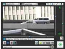
Operating
If an error message appears or the camera fails to operate correctly, see the error message and log message information in "Chapter 7 Appendix".
"Chapter 7 Appendix"

Important
Before starting operations, make sure that the setting page and Admin Tools settings are functioning correctly.
Installing the Necessary Software
Install the following software to perform initial settings for the camera.
- Camera Management Tool: Software required for performing initial camera settings and maintenance
- Admin Tools Certificate: An electronic certificate that is required for using Admin Viewer and Admin Tools
- Camera Angle Setting Not Software to use for camera angle adjustments when installing the camera
- .NET Framework 3.5 SP1/.NET Framework 4.5: The execution environment required for network camera software (not required if already installed on the PC)
You can perform either an Easy Installation or a Custom Installation of the software.

Note
- All computer users will be able to use Admin Viewer and Admin Tools if the Admin Tools certificate was installed by the installer.
- Select [Custom Installation] and install only the "Admin Tools Certificate" if you intend to use the Admin Viewer and Admin Tools on a PC other than the one where the Camera Management Tool is installed.
- If you install the software with Easy Installation, the Camera Angle Setting Tool that is not used with VB-H43/VB-M42 is also installed. If you do not want to install the Camera Angle Setting Tool because you are using only VB-H43/VB-M42 cameras, perform a [Custom Installation] and clear the checkbox for the Camera Angle Setting Tool.
1 Insert the Setup CD-ROM included in the camera in the disc drive on the PC.
2 After confirming that all other applications have been closed, click the [Start] menu > [My Computer].
3 Double-click the CD-ROM icon > [Applications] folder > [VBToolsInstall.exe].

The installation screen appears.

Note
If the [User Account Control] screen appears, click [Yes] or [Continue].

4 Select the installation method.
[Easy Installation]: Camera Management Tool, Admin Tools certificate and Camera Angle Setting Tool are installed.

[Custom Installation]: The user can select and install desired software.

5 After selecting [Easy Installation], click [Next] and after selecting [Custom Installation], select the checkboxes of the software you want to install and click [Next].
The User License Agreement screen appears.

6 Read through the user license agreement and click [Yes] if you accept it.
Installation starts.
7 When the installation complete screen appears, click [Exit] or [Reboot].

The Camera Management Tool and Camera Angle Setting Tool icons appear on the desktop.
![CANON VB-M720F - When the installation complete screen appears, click [Exit] or [Reboot]. - 2](/content/2026/08/1575110/images/f000085930a3455c0202d23c889236155ea156c84a0457ad388efc36284f34f5.jpg)
Camera Management Tool
![CANON VB-M720F - When the installation complete screen appears, click [Exit] or [Reboot]. - 3](/content/2026/08/1575110/images/b5b5cd583aeedd10b19aad521f58568952985570be16e8fb80a9965bd46ae4af.jpg)
Camera Angle Setting Tool
Making Initial Camera Settings
To use the camera, you must first set the network settings for the camera and then establish a network connection between the camera and a computer. Use Camera Management Tool for these settings. This section will explain, in addition to network settings, how to set the camera name, the date and time and other settings. It will also explain how to use the Camera Management Tool to make initial camera settings.

Note
- For details on using Camera Management Tool, please refer to "Camera Management Tool User Manual".
- The settings made here will be reflected in the settings on the Setting Page (p. 45).
Launch the Camera Management Tool
Launch the Camera Management Tool that was installed onto the computer from the setup CD-ROM.
1 Connect the camera and computer to the network and turn on the power.
Please refer to "Installation Guide" > "Connecting the Camera".
2 Double-click the [Camera Management Tool] icon on the desktop.

Camera Management Tool
Camera Management Tool launches and the [Camera Search Settings] dialog box appears.
3 Enter the factory default password ("camera") into [Administrator Password] and click [OK].

The Camera Management Tool main screen will appear.
Searching for Cameras and Setting up Networks
This will explain network settings so you can search for network connected cameras and connect to them from a computer.
The examples will be for setting one camera. The Camera Management Tool, however, can set multiple cameras at the same time.
1 Click the [Search Camera] icon.

Detected cameras will appear in the camera list.
2 Select a camera in the camera list and click the [Basic Camera Settings] icon.

The [Basic Camera Settings] dialog box appears.
3 Set each of the [Network] items.

(1) [IPv4 Address Setting Method]
Select the method for setting the IPv4 address. If [Manual] is selected, directly enter values that suit the environment in which the camera is used. If [Auto (DHCP)] is selected, the value automatically acquired from the DHCP server will be entered in [IPv4 Address], [Subnet Mask] and [IPv4 Default Gateway Address].
(2) [IPv4 Address]
If you selected [IPv4 Address Setting Method] > [Manual], enter a fixed IPv4 address.
(3) [Subnet Mask]
If you selected [IPv4 Address Setting Method] > [Manual], enter the designated subnet mask values for each network.
(4) [Enter a default gateway address] checkbox
Select this to manually set the default gateway address.
(5) [IPv4 Default Gateway Address]
Be sure to set this if you select [IPv4 Address Setting Method] > [Manual] and connect to the camera with a different subnet than that of the viewer.
(6) [AutoIP]
Select this to enable or disable AutolP.
(7) [IPv4 Address (AutoIP)]
When [Enable] is selected for [AutoIP], an automatically set IPv4 address is displayed.
4 Click [OK].
The camera will restart and the settings will take effect.
When you click [OK], other settings in ([Password], [Date and Time], [Camera], [Video]) [Basic Camera Settings] will also take effect.
Set the Password, Date and Time, Camera Name and Video
Set basic camera information, such as the camera name, administrator password and date.
Once you have entered information for each item, click [OK].
■ Password Setting
Click [Password] and set the administrator password.

Important
To ensure system security, be sure to change the administrator password. Do not forget the new password.

■ Date and Time Settings
Click [Date and Time] and make settings such as the camera date and time setting method, time zone, and daylight saving time.
For details on each item, please refer to "Setting" (p. 54) in "[Date and Time] Setting Date and Time".

■ Camera Name Setting
Click [Camera] and set the camera name displayed in the viewers and other software.
For setting details, please refer to "Camera Name" (p. 56) in "[Camera] Setting Initial Camera Settings and External Device Name".

■ Video Settings
Click [Video] and configure the size and quality settings of the video transmitted from the camera.
For setting details, please refer to "[Video] Setting Video Size, Quality and Frame Rate" (p. 61).

Registering Camera's IP Address to Trusted Sites
With Internet Explorer 9 or greater and Windows Server 2008/Windows Server 2012, Internet Explorer's security level for Internet and intranet sites is set to [High] by default.
As a result, it may be necessary to register the camera's IP address as a trusted site to access the Admin Viewer/VB Viewer, Setting Page or Admin Tools.
1 Select a camera from the camera list.
2 Click [Maintenance] menu > [Add to Trusted Sites].
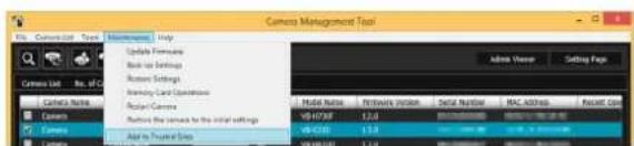
A confirmation message appears.
3 Click [Yes].
The camera will be registered as a trusted site for Internet Explorer.

Note
The registered information will be loaded when Internet Explorer is restarted. Close and restart Internet Explorer if it is running.
Access the Top Page of the Camera to Check Video
2
When initial camera settings are complete, access the camera with the Camera Management Tool and check if video can be viewed properly.
Access the Top Page from Camera Management Tool
You can use the Camera Management Tool to launch the camera top page.
1 Launch the Camera Management Tool (p. 28).
2 Double-click the IPv4 address of a camera in the camera list to launch its top page.

The web browser will start and the camera top page appears.

Note
- The web browser will not start when [Connection Status] for a camera is [Not connectable].
- You can also launch the camera top page by entering the IP address configured with the Camera Management Tool (p. 28) directly into the web browser.
- If the camera top page does not launch, please refer to "Troubleshooting" (p. 166)
Top Page
From the top page of the camera, you can navigate to the Setting Page to configure various camera settings, launch Admin Tools, and access Viewers to view video.
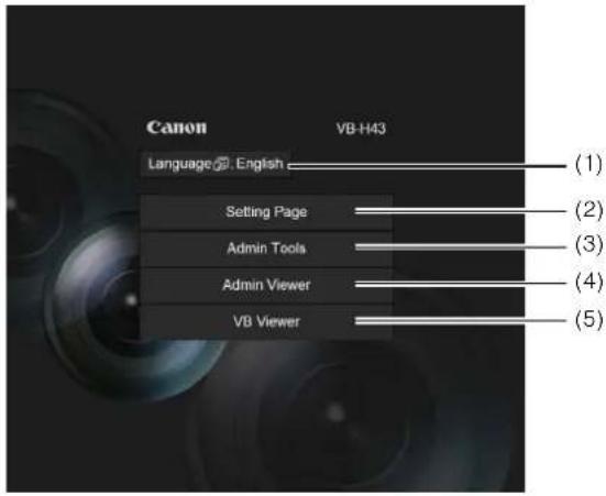
(1) Language Button
Click to switch the display language.
(2) [Setting Page]
Displays the Setting Page (p. 48).
You can make initial camera settings and settings to suit how the camera will be used.
(3) [Admin Tools]
Displays the Admin Tools top page (p. 92).
You can launch various tools for making settings, such as for using the camera, or launch a utility for managing recorded video.
(4) [Admin Viewer]
Launches the Admin Viewer (p. 32).
(5) [VB Viewer]
Launches the VB Viewer (p. 32).
■ User Authentication
When you use the Setting Page, Admin Tools or Admin Viewer, an authentication screen appears, and you are prompted to enter a user name and password. If you enter the wrong user name or password, you will not be able to connect to the camera. Enter the correct user name and password and connect to the camera.
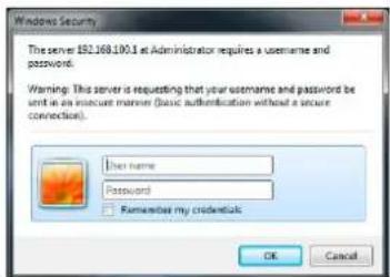
Authentication Screen for Setting Page

Authentication Screen for Admin Tools/Admin Viewer
The factory default user name and password are:
User Name: root
Password: camera
The user name "root" is the administrator account for the camera.

Important
- To ensure system security, be sure to change the administrator password. Do not forget the new password.
- Restore factory default settings if you have forgotten the administrator password (p. 180). Note that this will reset all camera settings to factory default settings except for date and time.
- If you connect to the camera using the administrator account, it will not be possible to connect with administrator privileges from a different computer.
- If the administrator and an authorized user share the VB Viewer on the same computer, it is strongly recommended that the [Remember my credentials] check box be cleared.
- The Admin Tools and the Admin Viewer cannot be used if an IPv6 address is specified. Only host names are supported for IPv6 connections.

Note
- Only administrators can connect to a camera using the Setting Page and Admin Tools.
- Authorized users with camera control privileges can also connect using Admin Viewer. You can set the user privileges of registered users with [Access Control] > [User Authority] on the Setting Page (p. 75).
- Depending on the security settings in Internet Explorer, the blocked content dialog box may appear when attempting to access the Setting Page, Admin Tools or the Viewers when using the camera with Internet Explorer 9 or greater, or on Windows Server 2008/Windows Server 2012. If this happens, click [Add] to register the camera IP address as a trusted site.

Checking Camera Video
Check the camera video with a viewer. VB Viewer and Admin Viewer are available.
This section only explains how to launch a viewer for checking video. For details on how to use each Viewer, please refer to "Admin Viewer/VB Viewer" (p. 135).

Note
If the blocked content dialog box appears when you launch a viewer, click [Add] in the dialog box to register the camera's IP address as a trusted site.
■ Viewing Video With VB Viewer
VB Viewer allows any user with camera access to use the camera. The user, however, is restricted to a limited set of functions.
When you click [VB Viewer] on the top page, the VB Viewer launches and displays the camera video.

■ Viewing Video With Admin Viewer
The Admin Viewer can only be used by administrators and registered users with camera control privilege. It allows complete control of the camera.
1 Click [Admin Viewer] on the top page.
The user authentication window appears.
2 Enter a user name and password (p. 31) and click [OK].

The Admin Viewer launches and displays the camera video.

2
Chapter 3
Camera Angle Setting Tool H630 H730 M620 M720
☐ Camera Angle Setting Method
□ Creating a Camera Specification File to Manage Multiple Cameras
Setting the Camera Angle
Use the Camera Angle Setting Tool to adjust the camera angle when installing the camera or to change the capture orientation according to the situation.
The following gives an overview of the settings that can be made with the Camera Angle Setting Tool.
H630 M620 Pan, Tilt, Rotation, Zoom, Image Flip, Focus
H730 M720 Zoom, Image Flip, Focus

Important
- The Camera Angle Setting Tool is included for angle adjustment during camera installation only and is not intended for daily use. Overuse may cause the camera to malfunction.
• After changing settings in the Camera Angle Setting Tool, check the settings in the Setting page and Admin Tools operate as intended. - The Camera Angle Setting Tool cannot be used via a proxy server.
- Upload functions cannot be used while the Camera Angle Setting Tool is connected.
Launching the Camera Angle Setting Tool
1 Double-click the Camera Angle Setting Tool icon on the desktop to launch the Camera Angle Setting Tool.


Note
You can also launch the Camera Angle Setting Tool from the Camera Management Tool. For details, please refer to the Camera Management Tool user manual.
Connecting to the Camera
1 Click [Connect] from the [File] menu.
![Camera Angle Setting Tool - [Not connected] File View Help Connect.. Select Camera.. Day/Night Mode Focus Settings.. Disconnect Exit](/content/2026/08/1575110/images/87d442d4059943d60e2bd55a253325470327c286c51f0dc7764e053d407492bf.jpg)
The [Connection settings] dialog box will appear.
2 Enter each item for the camera to connect to and click [OK].

[Host Name]
Enter the host name or IP address of the camera (p. 28).
[Administrator User Name]
Enter the administrator user name for the camera (p. 28).
[Administrator Password]
Enter the administrator password for the camera (p. 28).
[Enable SSL Communications] checkbox
Select this checkbox to connect to the camera using SSL communications. Normally SSL communications are not used (factory default setting) (p. 81).
[Port]
Set the HTTP port number to 80, 443 or in the range of 1024 to 65535. Normally [80] (factory default setting) is used (p. 70).
3 Click [Yes] at the following message.

![CANON VB-M720F - Click [Yes] at the following message. - 2](/content/2026/08/1575110/images/ab2384092d211773cfa36d1be2421cb052ddf97fd3dae01133779561cf6d90f4.jpg)
Note
When the Camera Angle Setting Tool connects to a camera, the viewer and recording software connected to the camera (excluding RTP connections) are disconnected.
A live camera image from the connected camera will be displayed and the camera angle can be set.


Important
- Access to one camera is restricted to 30 minutes. The Camera Angle Setting Tool will be disconnected automatically after 30 minutes. Reconnect if you do not complete camera angle settings within this time.
- One camera cannot be accessed by the Camera Angle Setting Tool from multiple PCs at the same time.
Connecting with a Camera List
When using multiple cameras, the camera connection information already entered into the camera specification file can be read into the camera list used by the Camera Angle Setting Tool. This way you can easily connect to multiple cameras without having to enter the camera information for each one. See "Creating a Camera Specification File" (p. 43) for information on how to create a camera specification file.
■ Loading a Camera Specification File
1 Click [Select Camera] from the [File] menu.
![Camera Angle Setting Tool - [Not connected] File View Help Connect... Select Camera... Day/Night Mode Focus Settings... Disconnect Exit](/content/2026/08/1575110/images/bfe8ca6d9c001ea30fef024792d517f28eee423b6c93d5febea6408212f54718.jpg)
The [Select Camera] dialog box will appear.
2 Click [Load camera specification file].

3 Select the camera specification file and click [Open].

The camera specification file will be loaded and camera names listed will be displayed under [Camera List].

![CANON VB-M720F - Select the camera specification file and click [Open]. - 3](/content/2026/08/1575110/images/f62a668dfd676053115b02e022d39de47bf6ce662294aaa96285224f0286b4f3.jpg)
Note
- The [Select Camera] dialog box will remain open unless the Camera Angle Setting Tool is shut down or the X at the top right of the dialog box is clicked.
- The camera list is discarded when the Camera Angle Setting Tool is shut down. Load the camera specification file the next time you launch the Camera Angle Setting Tool.
■ Connecting to the Camera
From the camera list, select the camera to connect to and click [Connect].

■ Connecting to the Next Camera on the List
Click [Next] to disconnect the camera currently connected and connect to the next camera on the list.


Note
In [Detailed Information], information for the camera selected in the camera list is displayed.
Disconnecting from the Camera, Shutting Down
1 Click [Disconnect] from the [File] menu to disconnect the currently connected camera.

2 Click [Exit] from the [File] menu to shut down the Camera Angle Setting Tool.


Important
Note that camera angle settings will be lost if you turn the camera on/off without performing the above steps.
H630 M620

H730 M720

(1) Video Display Area
The image captured by the camera is shown.
(2) [Switch Screen Size] button
Switches the display screen size between large display and small display. The display screen size can also be selected from [Display Screen Size] from the [View] menu.
(3) Control Assist H630 M620
Displays dotted lines showing the range of pan operation and tilt operation. The camera angle cannot be changed to positions with no dotted lines.
(4) [Pan] button H630 M620
Control the camera's pan operation.
(5) [Tilt] button H630 M620
Control the camera's tilt operation.
(6) [Rotation] button H630 M620
Control the camera's rotation operation.
(7) [Rotation] slider H630 M620
You can click on the slider or drag the knob to control the camera's rotation operation.
(8) Optical telephoto end icon
This is displayed when [Enable] is selected for [Digital Zoom]. Dragging the slider upward above this icon switches to the digital zoom.
(9) [Zoom] slider
The slider to operate the zoom ratio.
(10)[Zoom] button
The button to operate the zoom ratio.
(11)[Control Assist Display] selection box H630 M620
Select whether to [Enable] or [Disable] operation assist in the video display area.
(12)[Control Button Display] selection box H630 M620
Select whether to [Enable] or [Disable] the [Pan] button and [Tilt] button in the video display area.
(13)[Control Assist Correction] H630 M620
If the control assist display does not match the actual camera angle, click [Control Assist Correction] to confirm the actual camera angle and automatically correct the control assist display position. Control assist correction takes approximately 1 minute.
(14)[Digital Zoom]
Set digital zoom to [Enable] or [Disable]. If you select [Enable], the digital zoom boundary is displayed for the zoom slider and the digital zoom operation becomes possible.
The higher the digital zoom ratio, the lower the image quality becomes.
(15)[Image Flip] selection box
Select the orientation of the camera image.
If [Enable] is selected, the image will be rotated 180 degrees.
(16)[Focus]
You can control the focus.
(17)[Exposure Compensation] slider
You can control the exposure.

Important
You must set Intelligent Function detection areas, privacy masks and presets again after changing settings in the Camera Angle Setting Tool.

Note
This cannot be set for [Image Stabilizer].
Setting the Camera Angle
H630 M620 You can operate pan, tilt, rotation and zoom operations to set a desired camera angle.
H730 M720 You can operate zoom operation only.
■ Set Using the Operation Buttons and Sliders
H630 M620
Click each of the [Pan], [Tilt], [Rotation] buttons to set the camera angle. Camera angle changes in orientation if the button is held down, and stops when the button is released.


Pan (horizontal movement) operation


Tilt (vertical movement) operation


Rotation (angled movement) operation
To set rotation using the [Rotation] slider, drag the slider and release the mouse button when the subject in the image is shown at a level angle.

▼

■ Click the Image to Set Camera Angle
H630 M620
Click the desired position in the image and the camera angle will move to center that position on the screen. However, if the position clicked is beyond the range of the pan or tilt, the camera angle will move only in the pan or tilt direction that is within the valid range of movement.

Note
If the camera moves in a different way from operation control or cannot be set to the range indicated by operation assist, then operation assist may not correspond to the actual camera angle. Click [Control Assist Correction], then try to set the camera angle again.
■ Changing the Camera Zoom Ratio
The zoom ratio is set by using the [Zoom] buttons or [Zoom] slider.
[Zoom] buttons
Hold down to operate and release to stop.

Zoom in.

Zoom out.
[Zoom] slider
Drag the slider. The camera zoom ratio will change according to the position on the slider.
Setting Focus and Exposure Compensation
Setting the Focus
Use manual operations to focus on a desired position or fix at infinity. In manual operations, you can use the one-shot AF function to focus on the subject.

[Manual]:
You can adjust the focus manually by continuously pushing the (far) and (near) buttons.
Clicking [One-shot AF] will use autofocus to focus on a subject and then return to manual focus.
[Fixed at Infinity]:
You can set the focus so that it is fixed near infinity.

Note
- One-shot AF may not focus properly on the following subjects.
Subjects Difficult to Focus On
A white wall or other subject lacking bright/dark contrast

A slanting subject

A subject reflecting strong light

A subject consisting of only slant lines or horizontal stripes

A subject having no form, such as flame or smoke

A subject seen through glass

A fast moving subject

A dark area or night view

Subjects both near and far
- It is recommended that you check that the camera is focused whenever you restart the camera or use One-shot AF.
- Focus ranges (rough guide) are shown in the table below.
| Focus Mode | Day/Night Setting | |
| Day Mode | Night Mode | |
| Manual | 0.3 m (12 in.) – infinity 1 | 0 m (3.3 ft.) – infinity |
| Fixed at infinity | Focused at infinity* | |
^ When using an infrared lamp, the camera may be out of focus.
■ Setting the Exposure
You can set any of nine levels of image brightness (-4 to +4).

To darken the image, drag the slider toward [Dark]. To brighten the image, drag the slider toward [Bright].

Note
- If the camera's Exposure Mode (p. 153) was set to [Manual], it will be changed to [Auto] after setting exposure compensation.
- The exposure compensation value set with the Camera Angle Setting Tool will be reset when the camera is rebooted. The value will not be reflected in [Exposure Compensation] of [Camera] > [Initial Camera Settings] (p. 56) in the Setting Page.
Creating a Camera Specification File
You can load a camera list in the [Select Camera] dialog box (p. 37) if you create a camera specification file which lists connection information for cameras. The camera list allows for simple switching between camera connections for multiple cameras. Create a camera specification file beforehand using a text editor. The file must be saved in CSV file format.

Important
Enter the actual administrator passwords in the camera specification file. Handle the camera specification file with sufficient care.
■ Camera Specification File Content
The 1st row in the camera specification file is the header row. Enter a title for each column.
Camera information is listed for one camera per row starting from the 2nd row.
Enter the following information for each column.
| Column | Content |
| Registered Name The camera name. Displayed in the camera list during connection. | |
| Host Name The camera's host name or IP address. | |
| Port Number The camera's HTTP port (factory default setting is 80). | |
| Administrator User Name The camera's administrator user name (factory default setting is “root”). | |
| Administrator Password | The camera's administrator password (factory default setting is “camera”). |
| SSL Communications SSL communications: 1 No SSL communications: 0 (factory default setting is 0). | |
![graph TD A["1st row Header row"] --> B["RegisterName"] A --> C["B1F VB-H730F"] A --> D["1Fa VB-H630VE"] A --> E["1Fb VB-H630D"] B --> F["RegisterName"] B --> G["RegisterName"] C --> H["RegisterName"] C --> I["RegisterName"] D --> J["RegisterName"] D --> K["RegisterName"] E --> L["RegisterName"] E --…](/content/2026/08/1575110/images/2b32e9edd5065a0c96b28f170551bbb2661fd0af23833658cbc33b8cca396466.jpg)

Important
Up to 30 cameras can be registered. If camera information for more than 30 cameras is listed, an error will occur when the file is loaded into the Camera Angle Setting Tool.
■ Entering in a Text Editor
Separate each field with a comma. When you save the file, use the .csv file extension.
| RegisterName, HostName, PortNumber, UserName, Password, ConnectType |
| B1F VB-H730F, 192.168.100.1,80, root, camera1,0 |
| 1Fa VB-H630VE, 192.168.100.2,80, root, camera2,0 |
| 1Fb VB-H630D, 192.168.100.3,80, root, camera3,0 |
| 2Fa VB-H630D, 192.168.100.4,80, root, camera4,0 |
| 2Fb VB-H630D, 192.168.100.5,80, root, camera5,0 |
| 3Fa VB-H730F, 192.168.100.6,80, root, camera6,0 |
| R VB-H630VE, 192.168.100.7,443, root, camera7,0 |

Important
If the camera specification file includes delimiters other than commas, such as semicolons, the process of loading the camera specification cannot be performed.
Chapter 4
Setting Page
☐ Administrator Password and Network Detailed Settings
☐ Camera Date and Time Settings
☐ Camera Name and Initial Camera Settings Related Settings
☐ Video Size and Quality Settings
☐ RTP Streaming Settings
☐ Upload and E-mail Notification Settings
☐ Video Server, Audio Server, HTTP/FTP Server and WS-Security Settings
□Settings Related to Events
☐Administrator Password, User Registration/Authorities and Access Restriction Settings
IPsec Settings
☐ HTTP Communication Encryption (SSL/TLS) Settings
☐ 802.1X Authentication Settings
☐Memory Card Operations and Displaying Information
☐Settings for Items Requiring Rebooting
□ Maintenance (Displaying Log and Setting Information/Rebooting/Factory Default Settings)
Setting Menu
From the Setting Menu, you can navigate to each setting page to set various items regarding the camera. Information describing what can be set from each setting page is listed as follows. See each setting page for details.
![graph TD A["Setting Menu"] --> B["Data Input"] B --> C["Data Output"] C --> D["Maintenance"] D --> E["Output Module"]](/content/2026/08/1575110/images/ad78bbf57eb1b76b420b14e07c7fd3ff96fbc2c7877e1e51f0e3a296b9ec7e88.jpg)
- Network
Administrator password, LAN, IPv4, IPv6, DNS, mDNS and SNMP Settings (p. 50)
- Date and Time
Camera date and time, time zone and daylight saving time settings (p. 54)
- Camera
Camera name, initial camera settings, camera control, day/night, installation conditions, camera position control, external input device name and external output device name settings (p. 56)
- Video
Video quality, video size, and frame rate settings for the video size set, JPEG and H.264, as well as on-screen display settings (p. 61)
- RTP
RTP Server, Audio Multicast and RTP Streaming settings (p. 64)
- Upload
General upload and HTTP and FTP upload settings and e-mail notification settings (p. 66)
- Server
Video server, audio server, HTTP Server, FTP Server and WS-Security settings (p. 69)
- Event
Video record settings, volume detection, external device output, external device input, timer, and sound clip upload (p. 71)
- Access Control
Administrator Password, Authorized user account, user authorities, host access restriction settings (p. 75)
- I P s e c
IPsec settings (p. 77)
- SSL/TLS
Certificate creation, administrative settings and encrypted communication settings (p. 80)
• 8 0 2 . 1 X
802.1X authentication settings and authentication status display (p. 82)
- Memory Card
MEMORY card operations and information display (p. 84)
- Reboot Item
Setting items that require the camera to be rebooted (Reboot Item) (p. 87)
- Maintenance
Device information, displaying logs and current settings, rebooting, restoring initial settings, backing up/restoring settings and log notifications (p. 88)
- User Page
Link to web page customized by the user (For details, contact your nearest Canon Customer Service Center.)

Important
Notes on Use with Internet Explorer 8/9/10/11
If the pop-up is blocked and an information bar appears when attempting to access [View Logs] or [View Current Settings] on the maintenance page, enable Pop-up by following the procedure explained in the information bar.
Accessing the Setting Menu
The various settings of the camera are configured by accessing the camera in the web browser. First, access the top page of the camera (p. 31).
For details on entering the user name and password, see p. 31.

Note
You can also access the Setting Page from the Camera Management Tool. For details, please refer to the "Camera Management Tool User Manual".
Setting Menu

(1) [Admin Viewer]
Clicking this button opens Admin Viewer.
(2) [Back to top]
Clicking this button navigates to the top page.
(3) Setting Menu
Clicking this button navigates to each setting page.

Important
- To ensure security, exit the web browser after completing settings on the Setting page and after using Admin Viewer/Admin Tools.
- If the factory default administrator password is not changed, the message [The administrator password has not been changed. Please change the password.] will appear in the upper portion of the Setting Menu or of each Setting Page. To ensure security, be sure to change the administrator password (the message will disappear when the password is changed).
For details on changing the administrator password, please refer to p. 50.

Items Common to All Setting Pages
■ Applying New Settings
When a setting is changed on any setting page, [Apply] shown on the top right and bottom right of the setting page turns from grayed-out to blue.

Click [Apply] to make the new setting effective.
Click [Clear] to restore the previous setting.
■ Setting Changes Requiring Rebooting
Items that require the camera to be rebooted in order to change settings are flagged with an orange mark.

When any item accompanied by an orange mark is changed, the [Apply] shown at the top right and bottom right of each setting page changes to [Apply and reboot].

Click [Apply and reboot] to confirm the new setting. The new setting will be reflected and the camera will be rebooted.
Click [Clear] to restore the previous setting.

Important
Setting changes will be lost if you navigate to another setting page without clicking [Apply] or [Apply and reboot]. Be sure to click [Apply] or [Apply and reboot] to make the new settings effective.
■ Returning to the Setting Menu
Click [Settings menu] at the top right of each setting page to return to the Setting Menu.


Important
- Do not open multiple setting pages at one time and try to change the settings of a single camera.
- Do not use the [Back] or [Forward] buttons in the web browser to navigate between setting pages. The changed settings may return to the original settings or unwanted setting changes may be applied.

Note
Click on 📞 [Help] at the beginning of any item to display a detailed explanation of that setting item.
[Network]
Setting Administrator Password, LAN, IP Address, DNS, etc
The following can be set here.
- Administrator Password
Set the administrator password.
• LAN
Set the IP address and other items needed to establish a LAN connection.
• I P v 4
Set IPv4 address.
• I P v 6
Set IPv6 address.
• DNS
Set the name server address, host name and DDNS registration.
• m D N S
This will configure settings for using multicast DNS.
• SNMP
Configure the necessary settings to use SNMP.
Administrator Password
| Password Up to 8 characters | ********** |
| Confirm PasswordUp to 8 characters | ********** |
(1) [Password]
Set the administrator password. Up to eight (single-byte) ASCII characters (space or printable characters) can be used. The factory default setting is "camera". If the Admin Viewer, Admin Tools, etc., are connected, terminate the connection before changing the password.
(2) [Confirm Password]
Enter the same password as above for confirmation.

Important
- To ensure system security, be sure to change the administrator password. If it is not changed, a message prompting change of the password will appear continuously in the upper portion of the Setting Menu. The message will not disappear until the password is changed. Do not forget the new password.
- Press the reset switch to restore factory default settings if you have forgotten the administrator password (p. 180). Note, however, that this will reset all camera settings to factory default settings except for date and time.
- [Administrator Password] and [Access Control] > [Administrator Password] (p. 75) are the same. If you set one [Administrator Password], the setting will be reflected in the other [Administrator Password].
LAN
| LAN Interface | Auto |
| Maximum Packet Size575 - 1500 | 1500 |
(1) [LAN Interface]
Select [Auto], [Full Duplex] or [Half Duplex]. Normally [Auto] is used.
(2) [Maximum Packet Size]
Enter the maximum transmission unit. Normally there is no need to change the default setting of 1500.

Important
- The camera may become inaccessible from the active web browser if [LAN Interface] or [Maximum Packet Size] settings are changed. Check beforehand the precautions in "Important" in "[Reboot Item] Setting Items Requiring Rebooting" (p. 87).
- Set [Maximum Packet Size] to 1280 or greater if using IPv6.

Note
When using ADSL, setting the maximum packet size to a slightly lower value may increase sending efficiency.
IPv4
| IPv4 Address Setting Method | Manual |
| IPv4 Address | 192.168.100.1 |
| Subset Mask | 255.255.255.0 |
| IPv4 Default Gateway Address | |
| AutoIP | Enable |
| IPv4 Address (AutoIP) | 169.254.02.204 |
(1) [IPv4 Address Setting Method]
Select [Manual] or [Auto (DHCP)] in the address setting method. If [Manual] is selected, directly enter the values according to the environment in which the camera is used. If [Auto (DHCP)] is selected, the value automatically acquired from the DHCP server will be entered in [IPv4 Address], [Subnet Mask] and [IPv4 Default Gateway Address].
(2) [IPv4 Address]
If [Manual] is specified in (1), enter a fixed IP address.
(3) [Subnet Mask]
If [Manual] is specified in (1), enter the designated subnet mask values for each network.
(4) [IPv4 Default Gateway Address]
Enter an appropriate value if [Manual] is specified in (1). Be sure to set when connecting the camera to a different subnet from that of the viewer.
(5) [AutoIP]
Set AutoIP to [Disable] or [Enable].
(6) [IPv4 Address (AutoIP)]
When [Enable] is selected in (5), an automatically set IP address is displayed.
![CANON VB-M720F - [IPv4 Address (AutoIP)] - 1](/content/2026/08/1575110/images/9a2583e106b55e413a77a9da029f7cc7e46513bcd8688b1c729b8eb3b6777ef1.jpg)
Important
- Contact your System Administrator for the [IPv4 Address], [Subnet Mask] and [IPv4 Default Gateway Address].
- The camera's IP address cannot be set to an IP address that starts with 127., such as 127.0.0.1.
- If any of the [IPv4 Address], [Subnet Mask] or [IPv4 Default Gateway Address] settings is wrong, network access may be disabled. In this case, use Camera Management Tool to set the address again (p. 28).
- The camera may become inaccessible from the active web browser if settings are changed in [IPv4 Address], [Subnet Mask] or [IPv4 Default Gateway Address]. Check beforehand the precautions in "Important" in "[Reboot Item] Setting Items Requiring Rebooting" (p. 87).
- If [Auto (DHCP)] is selected as the IPv4 address setting mode, the IPv4 address may not be assigned correctly in certain environments, such as when a router is present between the DHCP server and the camera. In this case, assign a fixed IPv4 address from the [Manual] settings.
IPv6

(1) [IPv6]
Set IPv6 use to [Disable] or [Enable].
(2) [Auto (RA)]
Select [Enable] to set an address automatically using RA (Router Advertisement, network information automatically transmitted from a router), or select [Disable] not to set an address automatically.
(3) [Auto (DHCPv6)]
Select [Enable] to use DHCPv6 to set an address automatically or [Disable] not to set an address automatically.
(4) [IPv6 Address (Manual)]
Enter a fixed IPv6 address.
(5) [Prefix Length]
Enter a prefix length from 16 to 128 if [Disable] is specified in (2).
(6) [IPv6 Default Gateway Address]
Enter a default gateway address if [Disable] is specified in (2). Be sure to set when connecting the camera to a different subnet from that of the viewer.
(7) [IPv6 Address (Auto)]
If [Enable] is specified in (1) and [Enable] is specified in (2) and (3), then the automatically acquired address will be shown.
![CANON VB-M720F - [IPv6 Address (Auto)] - 1](/content/2026/08/1575110/images/e8053e534dd2d6396f44ea7a3188bc87bda207a0d7b2937aa74261c1d59f94ff.jpg)
Important
- Contact your System Administrator for the [IPv6 Address (Manual)], [Prefix Length] and [IPv6 Default Gateway Address].
- The camera may become inaccessible from the active web browser if settings are changed in [IPv6], [IPv6 Address (Manual)], [Prefix Length] or [IPv6 Default Gateway Address]. Check beforehand the precautions in "Important" in "[Reboot Item] Setting Items Requiring Rebooting" (p. 87).

Note
In an environment where IPv6 cannot be used, if IPv6 is set to [Enable] and auto is set to [Enable], then the [IPv6 Address (Auto)] field will display the link-local address only.
DNS

(1) [Name Server Address 1], [Name Server Address 2]
Enter the name server address you want to register. To register only one address, keep the [Name Server Address 2] field blank.
(2) [Auto-Setting of Name Server Address]
Select the method for setting the name server address automatically using DHCP. Select [Use DHCP] to use a name server address obtained automatically from the DHCP server. Select [Use DHCPv6] to use a name server address obtained automatically from the DHCPv6 server. Select [Use DHCP/DHCPv6] to use a name server address obtained automatically from the DHCP server or DHCPv6 server. Select [Disable] if not using DHCP.
To set [Use DHCP], select [Auto (DHCP)] in [IPv4 Address Setting Method].
To set [Use DHCPv6], select [Enable] in [IPv6], then select [Enable] in [Auto (DHCPv6)].
(3) [Name Server Address (DHCP)]
Select [Use DHCP] or [Use DHCP/DHCPv6] in [Auto-Setting of Name Server Address] to display the name server address acquired from the DHCP server.
(4) [Name Server Address (DHCPv6)]
Select [Use DHCPv6] or [Use DHCP/DHCPv6] in [Auto-Setting of Name Server Address] to display the name server address acquired from the DHCPv6 server.
(5) [Host Name]
You can register the host name of the camera in the name server.
Characters A to Z, a to z, 0 to 9, “-” (hyphen), “_” (underscore) and “.” (period) may be used up to 63 (single-byte) characters in length.
(6) [Host Name Registration with DDNS]
Select [Enable] to register the entered name server address and host name of the camera.
(7) [Search Domain]
When domain names are specified in the server domain list, search domains in the form "host name + domain name" by specifying the host name for a server, such as the upload server, without specifying a domain name. Enter a domain name and click [Add] to add the domain name to the search domain list.
(8) [Search Domain List]
A list of domain names added using [Search Domain] appears. The function queries DNS server for each domain name starting from the top of the list.
Use the ▲▼ buttons on the right to change the order of the domain names.
To delete a domain name, select one from the list and then click [Delete].
![CANON VB-M720F - [Search Domain List] - 1](/content/2026/08/1575110/images/ce6801ae4f592f40ddb02e5623c20ab420c79693fe1ac4bee73ce772c79773a7.jpg)
Important
Do not use “_” (underscore) in [Host Name] and [Search Domain] in Internet Explorer 8/9/10/11.

Note
- Use [Host Name Registration with DDNS] if the camera IP Address Setting Method is [Auto (DHCP)] (p. 50). DNS server registration settings must be set in advance. Contact your System Administrator for the DNS server settings.
- If the name server address 1 is unavailable, the name server address 2 will be accessed. However, the name server address 2 must be set in advance.
mDNS
| Use mDNS | Enable |
(1) [Use mDNS]
Set mDNS to [Disable] or [Enable]. If you use mDNS, the IP address and host name of the camera will be broadcast to other hosts on the network.
SNMP
| SNMP | ||
| Use SNMP v1 and v2c | Enable | + |
| Use SNMP v3 | Enable | + |
| Administrator Contact InformationUp to 32 characters | ||
| Administration Function NameUp to 34 characters | VB-H43 | |
| Installation Location Up to 34 characters | ||
| SNMP v1 and v2c Server | ||
| Community Name Up to 34 characters | group1 | |
| SNMP v3 Server | ||
| User Name Up to 34 characters | username | |
| Security Level | Authentication and encryption | + |
| Authentication Algorithm | MDS | + |
| Authentication PasswordBetween 8 and 31 characters | - | - |
| Encryption Algorithm | DES | + |
| Encryption Password Between 8 and 31 characters | - | - |
(1) [Use SNMP v1 and v2c]
Set SNMPv1, v2c use to [Disable] or [Enable]. Camera information can be referenced by the SNMP Manager if [Enable] is specified and SNMPv1 or v2c is used.
(2) [Use SNMP v3]
Set SNMPv3 to [Disable] or [Enable]. Camera information can be referenced by the SNMP Manager if [Enable] is specified and SNMPv3 is used.
(3) [Administrator Contact Information]
Set contact information (e-mail address, etc.) for the Administrator of the camera. Setting information can be referenced by the SNMP manager.
(4) [Administration Function Name]
Set the camera name used for administration. Setting information can be referenced by the SNMP manager. If left blank, the following will be used by default:
| H43 | VB-H43 |
| H630 | VB-H630VE or VB-H630D |
| H730 | VB-H730F |
| M42 | VB-M42 |
| M620 | VB-M620VE or VB-M620D |
| M720 | VB-M720F |
(5) [Installation Location]
Set information regarding the installation location of this camera. Setting information can be referenced by the SNMP manager.
SNMP v1 and v2c Server
(1) [Community Name]
When [Enable] is selected in [SNMPv1, v2c], enter a community name to be used for SNMPv1 and v2c. The default setting is blank.
SNMP v3 Server
(1) [User Name]
When [Enable] is selected in [SNMPv3], set the user name for using SNMPv3.
(2) [Security Level]
Select [No authentication and no encryption], [Authentication but no encryption] or [Authentication and encryption] for the SNMPv3 security level.
(3) [Authentication Algorithm]
When [Authentication but no encryption] or [Authentication and encryption] is selected for [Security Level], select [MD5] or [SHA1] for the authentication algorithm.
(4) [Authentication Password]
When [Authentication but no encryption] or [Authentication and encryption] is selected for [Security Level], set the authentication password.
(5) [Encryption Algorithm]
When [Authentication and encryption] is selected for [Security Level], select [DES] or [AES] for the encryption algorithm.
(6) [Encryption Password]
When [Authentication and encryption] is selected for [Security Level], set the encryption password.
![CANON VB-M720F - [Encryption Password] - 1](/content/2026/08/1575110/images/f5b6ecc465030367cf8adf6ed5b1732c94d1fca2733ac50ffa9586387bd77181.jpg)
Note
- The information set in the camera is read-only from the SNMP manager.
- Use the SNMP Manager that supports SNMP MIB2 (supporting RFC1213).
[Date and Time] Setting Date and Time
The following can be set here.
• Current Date and Time
The date and time set in the camera is shown.
- Setting
Select the date and time setting method, time zone and daylight saving time for the camera.
Current Date and Time
| Date: September | 2013/06/20 |
| Time: November | 21.08.21 |
[Date], [Time]
The date and time currently set in the camera are shown.
Setting
| Setting Method | Set manually | * |
| Date | 2013/05/26 | |
| Time Number | 21:06:56 | |
| Time Zone | (CMT-08:00) Pacific Standard Time (U.S. and Canada) | * |
| Daylight Saving Time | Disable | * |
(1) [Setting Method]
Select from [Set manually], [Synchronize with NTP server], [Synchronize with NTP broadcast], [Synchronize with computer time].
(2) [Date], [Time]
Set the following according to the selection made in [Setting Method].
[Set manually]
Set the desired date and time. The date is set by
[Synchronize with NTP server]
The camera will synchronize with the NTP server time.
| Setting Method | Synchronics with NTP broadcast |
| Time Zone | (GMT-06.06) Central Standard Time (U.S. and Canada) |
| Daylight Saving Time | Double |
[Synchronize with NTP broadcast]
The camera will synchronize with the NTP server time. The camera will synchronize time with NTP broadcasts received from the NTP server.
| Setting Method | Synchronization with computer time |
| Date syntner | 20.14/04/12 |
| Time Series | 13:44:16 |
| Time Zone | (DMT+99.06) Seoul |
| Daylight Saving Time | Disable |
[Synchronize with computer time]
The camera will synchronize with the date and time of the computer currently accessing the camera.
The [Time Zone] is not selected automatically, and must be set separately as required.
(3) [Auto-Setting of NTP Server]
When [Setting Method] is set to [Synchronize with NTP server], select a DHCP option for the automatic setting method of the NTP server.
| Setting Method | Synchrony with NTP Server |
| Auto-Setting of NTP Server | Disable |
| NTP Server Up to 10 characters | Time-run mid.gov |
| Time Zone | (SAT-06.00) Central Standard Time (U.S. and Canada) |
| Daylight Saving Time | Disable |
[Disable]
Select when specifying an arbitrary NTP server.
Enter the IP address or host name of the NTP server used in [NTP Server].
| Setting Method | Synchronization with NTP server |
| Auto. Setting of NTP Server | Use DHCP |
| NTP Server (DHCP) | |
| Time Zone | (GMT+09:00) Osaka, Sapporo, Tokyo |
| Daylight Saving Time | Disable |
[Use DHCP]
The camera time is synchronized with the time of the NTP server at the address acquired from the DHCP server. In order to set [Use DHCP], you must change [Network] > [IPv4 Address Setting Method] to [Auto (DHCP)] (p. 50).
The NTP server address acquired from the DHCP server will appear in [NTP Server (DHCP)].
| Setting Method | Synchronize with NTP series |
| Auto-Setting of NTP Server | Use DHCPs |
| NTP Server (DHCPs) | |
| Time Zone | (0MT+09:00) Osaka, Nagoya, Tokyo |
| Daylight Saving Time | Disable |
[Use DHCPv6]
The camera time is synchronized with the time of the NTP server at the address acquired from the
DHCPv6 server. In order to set [Use DHCPv6], you must change [Network] > [IPv6] to [Enable], then set [Auto (DHCPv6)] to [Enable] (p. 51).
The NTP server address acquired from the DHCPv6 server will appear in [NTP Server (DHCPv6)].
[Use DHCP/DHCPv6]
The camera time is synchronized with the time of the NTP server at the address acquired from the DHCP server or DHCPv6 server. If the NTP server (address) can be acquired from both the DHCP server (IPv4) and DHCPv6 server, the NTP server address acquired from the DHCP server (IPv4) will be used.
(4) [Time Zone]
Select from the list the appropriate time difference from the Greenwich Mean Time.
(5) [Daylight Saving Time]
Select [Enable] to automatically adjust the daylight saving time according to the time zone or [Disable] not to automatically adjust the daylight saving time.
![CANON VB-M720F - [Daylight Saving Time] - 1](/content/2026/08/1575110/images/6c82acca46783a9296053327f51fc3c67ba377c5ffd918baab53f6a74001a632.jpg)
Note
- If [Synchronize with computer time] is selected, after clicking [Apply], [Setting Method] will change to [Set manually].
- If [Synchronize with NTP server] is selected and the IP address of the NTP server is incorrect or a connection with the NTP server cannot otherwise be established, the date and time will not be changed.
- The NTP server query interval is 300 seconds. Synchronization will take time if the time difference is large.
- The camera's NTP broadcast mode does not support IPv6.
- If the [Time Zone] setting is changed, the date and time display will update automatically according to the specified time zone.
[Camera] Setting Initial Camera Settings and External Device Name
The following can be set here.
- Camera Name
Enter the name of the camera. The camera name is required for use with RM-Lite.
- Initial Camera Settings Sets shooting settings at camera start up.
- Camera Control
Set the digital zoom, image stabilizer, AGC limit, smart shade control strength, and pan/tilt speed control.
• Day/Night
Set the day/night switching mode.
• Installation Conditions
Sets installation conditions, such as LED settings.
- Camera Position Control
Set whether or not to limit the pan, tilt and zoom operations to the preset positions. Also, set the camera position when nobody has control privileges.
- External Device Name
Set the external input device name and external output device name.
Camera Name
| Camera Name (alphanumeric characters)Go to 10 characters | Camera |
[Camera Name]
Be sure to enter [Camera Name (alphanumeric characters)].
Up to 15 ASCII characters (spaces and printable characters) may be used for [Camera Name (alphanumeric characters)].
![CANON VB-M720F - [Camera Name] - 1](/content/2026/08/1575110/images/8e078ff583f301a7ed5c066aa7d6a3baea51c3abe31b37cb2bec8a6103e58eb3.jpg)
Note
- The camera name set here will be shown when the camera is registered for use with RM Viewer.
Initial Camera Settings
| AE Mode | Auto | → |
| Slow Shutter | Disable | → |
| Exposure Compensation | 0 | → |
| Metering Mode | Center-Weighted | → |
| Focus Mode | Auto | → |
| Smart Shade Control | Disable | → |
| White Balance | Auto | → |
| Noise Reduction | Standard | → |
| Sharpness | 3 | → |
| Color Saturation | 4 | → |
| Haze Compensation | Disable | → |
| Day/Night | Day Mode | → |
(1) [AE Mode], [Slow Shutter], [Shutter Speed]
Set the exposure control and shutter speed for the camera startup.
[AE Mode]
[Auto]
The exposure is controlled automatically. [Auto (Flickerless)]
In this mode, image flickers caused by fluorescent lights, etc., can be reduced. The shutter speed is automatically adjusted according to the brightness of the environment in which the camera is used.
[Auto (Shutter-priority AE)]
In this mode, a desired shutter speed can be specified.
[Slow Shutter]
Slow shutter can be used only if [Auto] or [Auto (Flickerless)] is selected in [AE Mode].
Set the maximum slow shutter time to be used when in auto exposure mode when capturing video in a dark place. Select [Disable], [1/15], [1/8], [1/4] or [1/2]. As slower shutter speed generates residual images when capturing a moving subject, select an appropriate time according to the capture conditions.
| AE Mode | Auto (Shutter-priority AE) |
| Shutter Speed | 1/100 |
[Shutter Speed]
Shutter speed can be used only if [Auto (Shutter-priority AE)] is selected in [AE Mode].
Select a desired shutter speed from the 16 levels from [1/2] to [1/16000]. When capturing a moving subject, selecting a higher shutter speed can reduce blurry image capture.
(2) [Exposure Compensation]
The exposure compensation when the camera starts can be set in the range of [-4 (Dark)] to [4 (Bright)]. To brighten the image, set a positive value. To darken the image, set a negative value.
The setting is not available if [Smart Shade Control] is set to [Auto].
(3) [Metering Mode]
Set the metering mode when the camera starts. [Center-Weighted]
The entire screen is metered by focusing on the center of the screen.
Even when slightly darker/brighter areas are present on the periphery of the screen, an appropriate exposure can be achieved for the subject near the center.
Use this mode if the subject is positioned near the center of the screen.
[Average]
The entire screen is metered by averaging.
A stable exposure can be achieved even in a capture environment where there are notable brightness differences within the screen.
Use this mode to stabilize the exposure in locations where vehicles or people are moving.
[Spot]
The center of the screen is metered.
An appropriate exposure can be achieved for the subject at the center of the screen regardless of the brightness/darkness on the periphery of the screen.
Use this mode if you want to adjust the exposure to the center of the screen because the subject is receiving a spotlight or backlight, etc.
(4) [Focus Mode] H43 M42
Set the focus mode when camera starts.
[Auto]
Automatically brings the subject into focus. Normally [Auto] is selected.
[Fixed at infinity]
The focus can be fixed to near infinity.
(5) [Smart Shade Control]
Set the smart shade control strength when the camera starts.
[Disable]
The smart shade control function is not used. [Manual]
Set the smart shade control strength. Select a strength from [1\ (Mild)] to [7\ (Strong)] in [Smart Shade Control Level].
| Smart Shade Control | Manual | ▼ |
| Smart Shade Control Level | 1 (Mild) | ▼ |
[Auto]
Combines the smart shade control function and the exposure compensation function to automatically adjust the video so that there are no blown out highlights or blocked up shadows. Accordingly, when [Auto] is selected, [Smart Shade Control Level] and [Exposure Compensation] are not displayed.
(6) [White Balance]
Select the white balance according to the light source to achieve natural color in the image.
[Auto]
The white balance is adjusted automatically. [Manual]
Set the values of red and blue gain according to the light source. Enter a value from 0 to 1023 for both the [R Gain] and [B Gain].
| # White Balance | Manual |
| # R Gain 0 - 1023 | 256 |
| # B Gain 0 - 1023 | 255 |
[Daylight Fluorescent]
Select this option to capture video under daylight fluorescent lighting.
[White Fluorescent]
Select this option to capture video under daylight fluorescent or white fluorescent lighting.
[Warm Fluorescent]
Select this option to capture video under warm fluorescent lighting.
[Mercury Lamp]
Select this option to capture video under mercury lamps.
[Sodium Lamp]
Select this option to capture video under orange sodium lamps.
[Halogen Lamp]
Select this option to capture video under halogen lamps or incandescent bulbs.
(7) [Noise Reduction]
Select a level from [Mild], [Standard], or [Strong] for the noise reduction setting.
Principally, this setting is more effective in low-light conditions. When set to [Strong], the noise reduction effect is increased, but the afterimage of moving subjects becomes easier to see. When set to [Mild], the noise reduction effect is decreased and resolution is increased, but the video file size becomes larger.
(8) [Sharpness]
Select a level from [1 (Mild)] to [7 (Strong)] for the sharpness setting.
When set to [Strong] the video becomes sharper, and when set to [Mild] the video becomes softer. Also, when set to [Strong] the video file size becomes larger.
(9) [Color Saturation]
Select a level from [1 (Light)] to [7 (Dark)] for the color saturation setting.
(10)[Haze Compensation]
If the subject is obscured by haze, this adjusts contrast in the video to improve subject visibility. [Disable]
Disables haze compensation.
[Manual]
Set the haze compensation strength. Select a strength from [1\ (Mild)] to [7\ (Strong)] in [Haze Compensation].
| Hazo Compensation | Manual | |
| Hazo Compensation Level | 4 |
[Auto]
Automatically uses haze compensation.
(11)[Day/Night]
Set Day/Night mode to [Auto], [Day Mode] or [Night Mode] when the camera starts.
You can also switch between [Day Mode] and [Night Mode] using the Day/Night mode function of the Admin Viewer (p. 155).
![CANON VB-M720F - (11)[Day/Night] - 1](/content/2026/08/1575110/images/bd9d4f8dc4dcaddb4cfcf6d32a14c259b1e954f06b62ffedcee03130ebb256ce.jpg)
Important
- The initial camera settings (1) to (11) define the defaults that apply when the camera is started. Setting changes will be reflected only after the camera is reconnected or rebooted. Specify the settings used in the actual operating environment from the Admin Viewer (p. 151).
- If the subject is a traffic signal or electronic scoreboard, etc., the captured image may flicker. In this case, try changing the [AE Mode] setting to [Auto (Shutter-priority AE)] and selecting a shutter speed lower than 1/100 to see if the problem improves.
- Setting a slow shutter speed may make it impossible for intelligent functions to work correctly. Select a shutter speed that suits the capture conditions and purpose.
- H43 di M42 where an outdoor scene is captured from an indoor location through a glass window, the camera may focus on the glass surface if there is dust or water there. Install the camera at the shortest possible distance from the glass surface.
- [Smart Shade Control] cannot be used if [Haze Compensation] is set to [Auto] or [Manual].
- [Haze Compensation] cannot be used if [Smart Shade Control] is set to [Auto] or [Manual].
- If [Auto] is selected for [Day/Night], conduct a thorough operation test to check the effectiveness of the setting beforehand.
- If [Auto] is selected for [Day/Night], set [Exposure] of the Admin Viewer to [Auto], [Auto (Flickerless)] or [Auto (Shutter-priority AE)] (p. 153). However, when [Auto (Shutter-priority AE)] is being used, night mode may not be activated even if [Day/Night] is set to [Auto], depending on the shutter speed.
- The Day/Night Mode can be switched manually via the Day/Night function of the Admin Viewer (p. 155), or via the [External Device Input] (p. 72) or [Timer] (p. 73) settings in [Setting Page] > [Event].
- To use with infrared illumination, set [Day/Night] to [Manual].
- When Day Mode and Night Mode are switched, the image may not focus correctly depending on the brightness.
- If [Day/Night] is set to [Auto], the infrared cutoff filter may move several times while the mode is switching between Day Mode and Night Mode. Pan, tilt, zoom and manual focus will not work during this period.

Note H43 M42
• See "Subjects Difficult to Focus On" (p. 42).
- It is recommended that you check the focus after rebooting the camera.
- Focus ranges (rough guide) are shown in the following table according to the settings of [Day/Night (when Auto is set)], etc.
| Focus Mode | Dome Setting | Day/Night Setting | |||
| Day Mode Night Mode | |||||
| Wide end | Tele end | Wide end | Tele end | ||
| Auto | Do not use | 0.3 m (12 in)– infinity | 1.0 m (3.3 ft)– infinity | 1.0 m (3.3 ft)– infinity | 1.5 m (4.9 ft)– infinity |
| Use 2.0 m (6.6 ft) – infinity | 1.0 m (3.3 ft)– infinity | 2.2 m (7.2 ft)– infinity | |||
| Fixed at infinity | Do not use/ Use | Focused at infinity* | |||
* When using an infrared lamp, the camera may be out of focus.
Camera Control
| Digital Zoom | Disable | |
| Image Stabilizer | Disable | |
| AGC Limit | 5 | |
| Smart Shade Control Strength (Auto) | Medium | |
| Haze Compensation Strength (Auto) | Medium | |
| PanTilt Speed Control | Control by zoom position |
(1) [Digital Zoom]
H43 M42
Set digital zoom to [Disable] or [Enable]. The higher the digital zoom ratio, the lower the image quality becomes.
(2) [Image Stabilizer]
H43 M42
Select [Disable], [On1] or [On2] for image stabilizer. The image stabilizer function has the effect of correcting blurry images caused by movement of the camera. Try [On2] if the image is still blurry after selecting [On1]. If you have selected [On1] or [On2] as the image stabilizer setting, the viewing angle will be smaller and the image more coarse than when [Disable] is selected. This is not a malfunction.
(3) [AGC Limit]
Select one of 5 levels from 1 to 5 to automatically set the upper gain limit. The greater the value, the higher the sensitivity becomes. If you do not want to use the automatic gain adjustment, select [OFF]. Setting the [AGC Limit] allows you to record with reduced noise when recording in low light conditions.
(4) [Smart Shade Control Strength (Auto)]
Select [Mild], [Medium], or [Strong] for the control strength when [Smart Shade Control] (p. 57) is set to [Auto].
• [Mild]: Select this when noise reduction is a priority.
- [Medium]: Recommended setting for auto mode (factory default setting).
• [Strong]: Select this when visibility in dark areas of the scene is a priority.
(5) [Haze Compensation Strength (Auto)]
Select [Mild], [Medium], or [Strong] for the haze compensation strength when [Haze Compensation] (p. 57) is set to [Auto].
When [Haze Compensation] is set to [Auto] and [Haze Compensation Strength (Auto)] is set to [Strong], contrast may be strong if the subject is not obscured by haze. If this happens, set [Haze Compensation Strength (Auto)] to [Mild].
(6) [Pan/Tilt Speed Control] H43 M42
Select [Control at set speed] or [Control by zoom position] for the pan/tilt control mode. If [Control by zoom position] is selected, the pan/tilt speed will be slower in the telephoto zoom range, and faster in wide-angle zoom range.
![CANON VB-M720F - [Pan/Tilt Speed Control] H43 M42 - 1](/content/2026/08/1575110/images/3426cb33f1c64c33424b7b0273da4e6b83442c5d6df9dc24a2655245b21f59a6.jpg)
Important
- [AGC Limit] is disabled when [Exposure] is set to [Manual] or [Auto (Flickerless)] in the Admin Viewer.
- Minimum subject illumination may change when [AGC Limit] is set.
H43 M42
- If [On2] is selected for [Image Stabilizer], it is best to select a video size smaller than "960 x 540".
- The image stabilizer is not effective when the subject is shaking.
- The image stabilizer is not effective beyond a certain level of vibration or against momentary vibration.
- See "Important" on p. 97, p. 104, p. 110 for precautionary notes regarding Admin Tools configuration when image stabilizer is set.
- See "Important" on p. 150 for precautionary notes regarding the Viewer when image stabilizer is set.

Note
- [Pan/Tilt Speed Control] can also be set using [Pan/Tilt] in the Control for Admin panel of the Admin Viewer (p. 152).
- If [Control by zoom position] is selected, [Control for Admin] > [Pan/Tilt] will also be fixed at [Control speed by zoom position].
Day/Night (when Auto is set)
| Switching Brightness | Standard | |
| Response (sec.) | 20 |
(1) [Switching Brightness]
Set the brightness at which Day Mode and Night Mode will be switched when [Auto] is selected in [Day/Night]. Select [Darker], [Slightly Darker], [Standard], [Slightly Brighter] or [Brighter]. Select [Darker] if you want to capture video in color as much as possible. Select [Brighter] to reduce noise. Note that this mode switches to black & white sooner.
(2) [Response (sec.)]
Set the time in seconds needed for judgment on switching between Day Mode and Night Mode when [Auto] is selected in [Day/Night]. Select [60], [30], [20], [10] or [5]. The mode will switch between Day Mode and Night
Mode if brightness remains above or below the level set in (1) for the number of seconds specified. Select [30] or [60] if brightness changes frequently, such as when a light source passes in front of the camera. Select [5] or [10] if change in brightness is minimal.
Installation Conditions
| Dome | Do not use | |
| LED Setting | Turn On | |
| Image Flip | Disable |
(1) [Dome] H43 M42
Select whether or not a dome is used. To use the camera with a dome housing unit, select [Use].
(2) [LED Setting] H43 H730 M42 M720
Select [Turn Off] or [Turn On] for the LED operation status on the camera. Set to [Turn Off] if you do not want to turn on the LED.
H43 M42
Set to [Turn Off] if an optional indoor dome housing for the camera is used, if reflected LED light enters the capture area or otherwise interferes with image capture, or if you do not want to show that the camera is operating.
(3) [Image Flip]
Select [Disable] or [Enable] for the orientation of the camera video.
![CANON VB-M720F - [Image Flip] - 1](/content/2026/08/1575110/images/1e6ec63fdadc9929f007a104d000e177b360ae0cda2aae56b60ccaab560c339a.jpg)
Note
- For the focus ranges when the dome is set to [Use], see the note on p. 58.
• The BED with light for several
seconds when booting even if the [LED Setting] is set to [Turn Off].
Camera Position Control
| Restricted to Presets | No Restriction |
| Camera Position without Control | Do not return to Home Position |
(1) [Restricted to Presets] H43 M42
Set the camera control preset to [No Restriction] or [Preset Only]. The administrator can limit camera control by non-administrators to preset angles by selecting [Preset Only].
(2) [Camera Position without Control]
Select either [Do not return to Home Position] or [Return to Home Position] as the action when no control privileges are requested by users and the home position has already been set. When [Return to Home Position] is selected and no users have control privileges, the camera moves automatically to the home position. This function requires the home position of the camera be set in advance. Set the home position using Preset Setting Tool (p. 106).
External Input Device 1, 2 / External Output Device 1, 2
Device Name (alphanumeric characters) Up to 10 characters
[Device Name] for external input device/external output device
Be sure to enter each device name in order to identify the corresponding external device being connected. Enter [Device Name (alphanumeric characters)] using up to 15 characters (ASCII characters (space or printable characters) excluding the double quotation mark (“)).
![CANON VB-M720F - [Device Name] for external input device/external output device - 1](/content/2026/08/1575110/images/847aa4e392cabba259510c2950c57c4614664faee24cfad47762b3d24740fcc6.jpg)
Note
The external device name set here will be shown when the Admin Viewer or included RM-Lite is used.
[Video] Setting Video Size, Quality and Frame Rate
The following can be set here.
- All Videos
Specify the set of video sizes used by the camera.
- JPEG
Set the video quality, size, maximum frame rate and upload size in JPEG.
• H.264
Set the bit rate, video size and capture frame rate in H.264.
- On-screen display
Set time, character string, etc. displayed over images.
All Videos
[Video Size Set]
Select the set of video sizes used by the camera. All options in the [Video] menu and the size set that can be selected in [Video Size] are determined by the set selected here.
H43 H630 H730
| Video Size Set | 1920 x 1000 / 960 x 540 / 480 x 270 |
| [Video Size Set] | System | Aspect ratio |
| [1920x1080/960x540/480x270] | 1080p 16:9 | |
| [1280x720/640x360/320x180] | 720p 16:9 | |
| [1280x960/640x480/320x240] | 4:3 4:3 |
M42 M620 M720
| ∅ Video Size Set | 1280 x 720 / 640 x 360 / 320 x 180 |
| [Video Size Set] | System | Aspect ratio |
| [1280x720/640x360/320x180] | 720p 16:9 | |
| [1280x960/640x480/320x240] | 4:3 4:3 |
Important
- Changing the [Video Size Set] setting will disconnect all connections and then change all the video sizes. Consequently, users connected to the camera must reconnect.
-
If the [Video Size Set] selection is changed and you click [Apply and Reboot], review the following settings and check the operation.
-
Privacy mask settings
- View restriction settings
- Preset settings
- Intelligent function settings
- Camera Angle Setting Tool 20
JPEG
| Video Quality: 480 x 270 | 3 | - |
| Video Quality: 960 x 540 | 3 | - |
| Video Quality: 1920 x 1080 | 3 | - |
| Video Quality: Digital PTZ | 3 | - |
| Video Size: video Transmission | 480 x 270 | - |
| Maximum Frame Rate: Video Transmission | 30.0 | |
| Video Size: Upload / Memory card | 480 x 270 | - |
(1) [Video Quality]
Select a desired video quality from 1 to 5 (5 levels) for videos transmitted at each video size in JPEG. Greater values have higher quality.
(2) [Video Quality: Digital PTZ]
H630 H730 M620 M720
Select a desired video quality from 1 to 5 (5 levels) for Digital PTZ. Greater values have higher quality.
(3) [Video Size: video Transmission]
Select the size of the transmitted video. The video sizes that can be selected depend on the [Video Size Set] setting. The default video size is selected if the video size is not specified in each type of viewer.
(4) [Maximum Frame Rate: Video Transmission]
Limit the maximum transmission frame rate per second to reduce the viewer load. The maximum is 30 frames/sec. Enter a value of between 0.1 and 30.0.
(5) [Video Size: Upload / Memory card]
Select the size of video when using the upload function (p. 66) or when recording to a memory card (p. 84). The video sizes that can be selected depend on the [Video Size Set] setting. Use [Event] > [Video Record Action] (p. 71) to specify the destination of a video recording (upload or memory card recording).
H.264(1)
| 1 Video Size | 480 x 270 | √ |
| 2 Bit Rate Control | Use bit rate control | √ |
| 3 Target Bit Rate (kbps) | 2645 | √ |
| 4 Frame Rate (fps) | 36 | √ |
| 5 Frame Interval (sec) | 1 | √ |
Configure settings using H.264(1) when using H.264 video for upload or memory card recording. H.264(2) video cannot be used for upload or memory card recording.
H.264(1) video can be displayed using Admin Viewer and RM-Lite Viewer. It cannot be displayed using VB Viewer.
(1) [Video Size]
Select the size of the transmitted video. The video sizes that can be selected depend on the [Video Size Set] setting.
(2) [Bit Rate Control]
Select [Do not use bit rate control] or [Use bit rate control].
Select [Use bit rate control] when [Video Format] under [Upload] is set to [H.264(1)] or when [Video Format] under [Memory Card] is set to [H.264(1)].
(3) [Target Bit Rate (kbps)]
If [Use bit rate control] is selected in (2), select a desired target bit rate from the 17 levels from [64] to [16384].
| Bit Rate Control | Do not use bit rate control |
| Video Quality | 3 |
(4) [Video Quality]
If [Do not use bit rate control] is selected in (2), select a desired quality from 1 to 5 (total 5 levels) for H.264 video transmission.
Greater values have higher quality.
(5) [Frame Rate (fps)]
Select [30], [15], [10], [6], [5], [3], [2] or [1] (fps) for the frame rate of video transmitted.
(6) [I Frame Interval (sec)]
Select [0.5], [1], [1.5], [2], [3], [4] or [5] for the I frame interval (sec) for H.264 video.
H.264(2)
| 11.264(Z) | Enable | |
| Video Size | 489 x 270 | |
| Bit Rate Control | Use bit rate control | |
| Target Bit Rate (kbps) | 2048 | |
| Frame Rate (fps) | 30 | |
| Frame Interval (sec) | 1 |
(1) [H.264(2)]
Select [Enable] to distribute H.264 video using two streams.
H.264(2) video can be displayed using Admin Viewer and RM-Lite Viewer. It cannot be used for upload, memory card recording, or by VB Viewer.
Refer to the settings for "H.264(1)" for details about [Video Size], [Bit Rate Control], [Target Bit Rate (kbps)], [Video Quality], [Frame Rate (fps)], and [I Frame Interval (sec)] settings.
![CANON VB-M720F - [H.264(2)] - 1](/content/2026/08/1575110/images/a466c52564f009895444e088a87890b4c0e49e5446c87d55bd4ef55453d4498f.jpg)
Important
- When streaming two H.264 videos, setting the video size settings for H.264(1) and H.264(2) to the following combinations restricts the frame rate to a maximum of 15 fps. For all other combinations, a frame rate of up to 30 fps can be selected.
| H.264(1) H.264(2) | |
| 1920 x 1080 All sizes | |
| All sizes 1920 x 1080 | |
| 1280 x 960 1280 x 960 | |
| 1280 x 720 1280 | x 720 |
- When [H.264(1)] is selected for the memory card recording and upload settings, the following restrictions apply to the [H.264(1)] setting.
- Only [Use bit rate control] can be selected for [Bit Rate Control].
- Only [3072] or less can be selected for [Target Bit Rate (kbps)].
- Only one of [0.5], [1], and [1.5] can be selected for [I Frame Interval (sec)].
- Network load will increase if a larger video size is set or higher video quality and target bit rate are set, as this increases data size per frame. As a result, the following could occur:
JPEG: The frame rate may drop
H.264: Video may be temporarily disrupted
- Block noise may become noticeable if a large video size and low target bit rate are set.
- The data size may increase depending on the type or movement of the subject. If the frame rate remains low or other undesirable conditions continue for a prolonged period, lower the video size or quality setting.
• The included RM-Lite cannot record H.264 video.
- H.264 video can be displayed using Admin Viewer and RM-Lite Viewer. H.264 video cannot be displayed using VB Viewer.
On-screen display
| Date display | Enable | ▼ |
| Position of date display | Upper left | ▼ |
| Format of date display | YYYY/MM/DD | ▼ |
| Time display | Enable | ▼ |
| Position of time display | Upper left | ▼ |
| Text display | Display designated string | ▼ |
| Position of text display | Upper left | ▼ |
| Text string display Up to 16 characters | Entrance | |
| Color of text | White | ▼ |
| Background color | Black | ▼ |
| Color depth of text and background | Fill text and background color | ▼ |
(1) [Date display]
Select whether to enable date display over images. If [Enable] is selected, date information will be displayed over images.
(2) [Position of date display]
Select [Upper left], [Upper right], [Lower left] or [Lower right] for the position of date display information.
(3) [Format of date display]
Select [YYYY/MM/DD], [DD/MM/YYYY] or [MM/DD/YYYY] for the format of the date display.
(4) [Time display]
Select whether to enable time display over images. If [Enable] is selected, display time information will be displayed over images.
(5) [Position of time display]
Select [Upper left], [Upper right], [Lower left] or [Lower right] for the position of time display information.
(6) [Text display]
Select [Display nothing], [Display designated string] or [Display camera name] for the text string to display over images. If [Display designated string] is selected, the [Text string display] set in (8) will be displayed. If [Display camera name] is selected, the text string set in [Camera Name (alphanumeric characters)] under [Camera] will be shown (p. 56).
(7) [Position of text display]
Select the position of text display from [Upper left], [Upper right], [Lower left] or [Lower right].
(8) [Text string display]
If [Display designated string] is selected in (6) [Text display], you can enter a text string of up to 15 ASCII characters (spaces and printable characters) for superimposed display on the video.
(9) [Color of text]
Select [Black], [Blue], [Cyan], [Green], [Yellow], [Red], or [Magenta], [White] for the color of text to be displayed over the image.
(10)[Background color]
Select [Black], [Blue], [Cyan], [Green], [Yellow], [Red], [Magenta], or [White] for the color of the text background.
(11)[Color depth of text and background]
Select [Fill text and background color], [Make text transparent], [Make background transparent], [Make text semi-transparent], [Make background semi-transparent], or [Make text and background semi-transparent] for the color depth of text and text background to be displayed over the image.
![CANON VB-M720F - (11)[Color depth of text and background] - 1](/content/2026/08/1575110/images/512d9e4cff1ec13e35aa52e6b17c73add3b1cffb98567a8c509ac7fd7259657d.jpg)
Important
The on-screen time display is not suitable for usage where high reliability is required. Use as reference information only where utmost and constant reliability is required for surveillance.

Note
- Depending on video quality settings, on-screen display may become difficult to decipher. Set after confirming appearance on actual images.
- H630 H730 M620 M720 The on-screen shown for cropped images using digital PTZ with horizontal size of 384 pixels or lower.
[RTP]
Setting RTP Server, Audio Multicast and RTP Streaming
The following can be set here.
- RTP Server
Enable RTP, and set the RTSP authentication method and port number. - Audio Multicast
Make settings for multicast audio transmission.
• R T P Streaming 1 to 5
Make settings for RTP streaming of video, multicasting, and audio transmission.
RTP Server
| 1 RTP | Enable | |
| 2 RTSP Authentication Method | Digest Authentication | |
| 3 RTSP Port 504, 1004-48888 | 664 |
(1) [RTP]
Set RTP to [Disable] or [Enable].
(2) [RTSP Authentication Method]
Set the RTSP authentication method to [Basic Authentication], [Digest Authentication], or [No Authentication].
(3) [RTSP Port]
Set the RTSP port number to 554 or in the range of 1024 to 65535.
Normally [554] (factory default setting) is used.
Audio Multicast
| Multicast Address | 0.0.0.0 | |
| Multicast Port IL 1024-2024 (even numbers only) | 0 | |
| Multicast TTL s.216 | 1 |
(1) [Multicast Address]
Set the multicast address for audio transmission in the range 224.0.0.0 to 239.255.255.255 (IPv4) or an address beginning with ff00::/8 (IPv6).
To disable Multicast, set to [0.0.0.0] (IPv4) or ::0(:):.
(2) [Multicast Port]
Set the multicast port number for audio transmission to an even number in the range 1024 to 65534. To disable Multicast, set to [0].
(3) [Multicast TTL]
Set the effective scope of multicast distribution between 0 and 255.
To disable Multicast, set to [0].
The TTL (Time To Live), representing the effective scope of multicast distribution, is decremented each time the signal passes through a router. When the
value reaches 0, the signal can no longer be distributed. For example, if TTL is set to [1], multicast distribution is confined to the local segment only and cannot be distributed by the router.
RTP Streaming 1 to 5
You can make settings for each stream, RTP Streaming 1 to RTP Streaming 5, in a 5-session RTP stream distribution.
| 1 Video Size | 489 x 270 JPEG | - |
| 2 Frame Rate : .36 | 5 | |
| 3 Multicast Address | 0.5.0.0 | |
| 4 Multicast Port: 0, 1624 - 8034 (rest numbers only) | 0 | |
| 5 Multicast TTL : .200 | 1 | |
| 6 Audio Transmission | Disable | - |
(1) [Video Size]
Select the video format (JPEG or H.264) and video size of the RTP stream. The video sizes for JPEG will vary depending on the [Video Size Set] configured in [Video] > [All Videos] (p. 61). The video sizes for H.264 will be determined according to the [H.264(1)] and [H.264(2)] settings configured in [Video]. In addition, [H.264(1)] and [H.264(2)] cannot be set for multiple RTP streams.
(2) [Frame Rate]
Set the frame rate if RTP streaming JPEG video. For H.264, the frame rate is determined by the [Video] > [H.264(1)] or [H.264(2)] > [Frame Rate] setting (p. 62).
(3) [Multicast Address]
Set the multicast address for RTP streaming in the range 224.0.0.0 to 239.255.255.255 (IPv4) or an address beginning with ff00::/8 (IPv6). To disable Multicast, set to [0.0.0.0] (IPv4) or ::0(:):.
(4) [Multicast Port]
Set the multicast port number for RTP streaming to an even number in the range 1024 to 65534. To disable Multicast, set to [0].
(5) [Multicast TTL]
Set the effective scope of multicast distribution for RTP streaming between 0 and 255. To disable Multicast, set to [0]. The TTL (Time To Live), representing the effective scope of multicast distribution, is decremented each time the signal passes through a router. When the value reaches 0, the signal can no longer be distributed. For example, if TTL is set to [1], multicast
distribution is confined to the local segment only and cannot be distributed by the router.
(6) [Audio Transmission]
Set RTP streaming audio transmission to [Disable] or [Enable].
![CANON VB-M720F - [Audio Transmission] - 1](/content/2026/08/1575110/images/d55d20f9b081ae2702a1e3ab7d3dac04330d1efb27ef405afdc824034f582b05.jpg)
Note
- RTP stream URL
rtsp://IP_address:port_number/rtpstream/config1(\~5)=r|u|m
[=r|u|m] is optional and can be omitted. If specified, specify only one option.
r: Requests RTP over TCP
u: Requests RTP over UDP
m: Requests multicast
Example: RTP streaming 1 request using RTP over TCP rtsp://192.168.100.1:554/rtpstream/config1=r
Note that the actual operation is dependent on the RTP client application, so the URL does not necessarily specify the method used for transmission.
- For H.264, the bit rate control and video quality are determined by the settings in [Video] (p. 62).
- Regardless of the [Server] > [Audio Server] > [Audio Transmission from the Camera] setting, RTP streaming audio will be used.
However, to use audio settings, select [Enable] for [Audio Transmission from the Camera] and make the settings.
- The [Access Control] > [User Authority] > [Video Distribution] and [Audio Distribution] settings are not used for RTP.
- RTP streaming video may not be viewable on systems using a proxy server or firewall. If the video cannot be viewed, contact the system administrator.
- If host access restrictions are applied to a client while it is streaming using RTP over UDP, it may take from a few to several seconds until streaming ceases.
[Upload]
Setting HTTP/FTP Upload and E-mail Notification
The following can be set here.
- General Upload
Set the upload operation to be performed and the image buffer.
- HTTP Upload Set HTTP connection uploads.
- FTP Upload Set FTP connection uploads.
• E-mail Notification
Set event information and image e-mail notifications.
General Upload
| Upload | HTTP Upload | |
| Video Format | JPEG | |
| Frame Rate 0.10 | 1 | |
| Pre-event Buffer (number of frames) 0.100 | 0 | |
| Post-event Buffer (number of frames) 0.100 | 0 | |
| Upload | FTP Upload |
| Video Format | H.284(1) |
| Pre-event Buffer (sec) s - s | 0 |
| Post-event Buffer (sec) s - ss | 0 |
(1) [Upload]
Select [Upload Disabled], [HTTP Upload] or [FTP Upload] for the upload method.
(2) [Video Format]
Select the [JPEG] or [H.264(1)] format for video you want to upload.
If [H.264(1)] is selected, video is uploaded with the settings defined under [Video] > [H.264(1)] (p. 62). [H.264(2)] cannot be used.
(3) [Frame Rate]
Enter the maximum frame rate of image to be uploaded. This setting can only be made when [JPEG] is selected for [Video Format].
(4) [Pre-event Buffer (number of frames)] / [Pre-event Buffer (sec)]
Enter the number of frames or seconds of video to be buffered before the event. The maximum amount is number of frames for a [JPEG] selection and number of seconds for an [H.264(1)] selection in [Video Format].
(5) [Post-event Buffer (number of frames)] / [Post-event Buffer (sec)]
Enter the number of frames or seconds of video to be buffered after the event. The maximum amount is number of frames for a [JPEG] selection and number of seconds for an [H.264(1)] selection in [Video Format].

Important
- If the upload function is used, either the [Event] menu must be set (p. 71) or the [Event] tab in the Intelligent Function Setting Tool (p. 120) must be set.
- If you are using both e-mail notification by text and image and image upload by HTTP/FTP, set [Video Size: Upload / Memory card] (p. 61) to a small size.
- HTTP upload does not support SSL/TLS.
- If the camera is set to perform upload or e-mail notification continuously, not all images or e-mails may be sent depending on the video size and the network condition to the server. In this case, an event log message is displayed (p. 88).
- If the destination for HTTP/FTP upload or e-mail notification is set for a Windows operating system, IPsec communication cannot be applied.
-
When an H.264 video is uploaded, the following restrictions apply to [H.264(1)] of [Video].
-
Only [Use bit rate control] can be selected for [Bit Rate Control].
- Only [3072] or less can be selected for [Target Bit Rate (kbps)].
-
Only one of [0.5], [1], and [1.5] can be selected for [I Frame Interval (sec)].
-
The maximum image buffer size capacity is approx. 5 MB. If a large video size is set, the Frame Rate, Pre-event Buffer and Post-event Buffer may not be achieved as specified.
- If buffering cannot be achieved as specified, a message is written to the event log (p. 88).
Before using a large video size, confirm that no messages appear in the event log.

Note
The server or network load may increase and the frame rate may drop, depending on the settings. If this occurs, try the following measures. Also check the settings including the network to the server.
- Reduce the image file size:
- Set a lower value under [Video Quality] for [JPEG]/[H.264(1)] (p. 61).
- Set a lower value for [Video Size: Upload / Memory card] for [JPEG] (p. 61).
- Set a lower value for [Video Size] for [H.264(1)] (p. 62).
- Set a lower value under [Target Bit Rate (kbps)] for [H.264(1)] (p. 62).
- Reduce the uploading frequency:
- Reduce the value in [Pre-event Buffer] or [Post-event Buffer] (p. 66).
- If [Volume Detection Event] is enabled, disabled [ON Event Operation], [OFF Event Operation], or [Ongoing ON Event Operation] (p. 71).
- From the Intelligent Function Setting Tool [Event] tab > disable [ON Event Operation], [OFF Event Operation] or [Detected mode Operation] (p. 120).
- If [External Device Input Event] is enabled, disable [Active Event Operation], [Inactive Event Operation], or [Ongoing Active Event Operation] (p. 72).
- If [Timer Event] is enabled, increase the value in [Repeat Interval] (p. 73).
HTTP Upload
The HTTP upload function sends notifications via HTTP or via HTTP with attached video, depending on the network camera event.
| 1 Notification | Notification Only with HTTP | |
| 2 URI Up to 208 characters | http://192.168.100.67/upload.cgi | |
| 3 User Name Up to 31 characters | ||
| 4 Password Up to 31 characters | ***** | |
| 5 Proxy Server Up to 53 characters | ||
| 6 Proxy Port 1-6550t | 80 | |
| 7 Proxy User Name Up to 31 characters | ||
| 8 Proxy Password Up to 31 characters | ***** | |
| 9 Parameter (query string) Up to 127 characters | ||
| 10 HTTP Upload Test | Exec | |
(1) [Notification]
Select [Notification Only with HTTP] or [Video attached Notification with HTTP] as the content of notification.
(2) [URI]
Enter the URI to be uploaded to (using up to 255 characters).
(3) [User Name], [Password]
Enter the user name and password required for authentication. Digest authentication is not supported.
(4) [Proxy Server]
Enter the host name or IP address of the proxy server (using up to 63 characters).
(5) [Proxy Port]
Enter the port number of the proxy server (factory default setting is [80]).
(6) [Proxy User Name], [Proxy Password]
Enter the user name and password of the proxy server. Digest authentication is not supported.
(7) [Parameter (query string)]
Enter the parameter (using up to 127 characters). Parameters can be specified using the “%” character (p. 164).
(8) [HTTP Upload Test]
Clicking [Exec] initiates an upload test based on the settings currently entered. Only one JPEG image is uploaded. It is not necessary to click [Apply].
After entering a password, first click [Exec], then [Apply] the password.

Important
- Enter [Proxy Server], [Proxy Port], [Proxy User Name] and [Proxy Password] if connecting via a proxy.
- For information about the HTTP upload function and settings, contact your nearest Canon Customer Service Center.
FTP Upload
| 1 Notification | Video data upload with FTP |
| 2 FTP Server Up to 62 characters | 192 108 109.67 |
| 3 User Name Up to 24 characters | 4p |
| 4 Password Up to 63 characters | ********** |
| 5 PASV Mode | Enable |
| 6 File Upload Path Up to 205 characters | |
| 7 File Naming | YYMMDDHHMMSSnis |
| 8 FTP Upload Test | Exec |
(1) [Notification]
The content of notification is set to [Video data upload with FTP].
(2) [FTP Server]
Enter the host name or IP address of the FTP server (using up to 63 characters).
(3) [User Name], [Password]
Enter the user name and password required for authentication.
(4) [PASV Mode]
Select [Disable] or [Enable] for the PASV mode when uploading via FTP.
(5) [File Upload Path]
Enter the path to the folder where the image file is to be uploaded to (using up to 255 characters).
(6) [File Naming]
Set a desired file naming rule.
[YYYYMMDDHHMMSSms]
Images are uploaded according to the file name format of
"{year}{month}{day}{hour}{minute}{second}{ms}.jpg". (Example: 20150123112122000.jpg)
[YYYYMMDD Directory/HHMMSSms]
A subdirectory named "{year}{month}{day}" is created first, and then the image is uploaded using the file name "{hour}{minute}{second}{ms}.jpg". (Example: 20150123/112122000.jpg)
| File Naming | Loop |
| Maximum Number of Loops - 0 mm | 100 |
[Loop]
Images are loaded with a file name numbered up to the value set in [Maximum Number of Loops].
(Example: 0000.jpg, 0001.jpg)
The number will return to 0000 when the maximum number of loops is reached.
[Maximum Number of Loops]
If [Loop] is set under [File Naming], enter the maximum number of loops in the range of 0 to 9999.
| File Naming | User Setting |
| Subdirectory Name to CreateUp to 137 characters | |
| File Name to Create Up to 137 characters | image.jpg |
[User Setting]
Images are uploaded according to the file naming method specified in [Subdirectory Name to Create] and [File Name to Create].
[Subdirectory Name to Create], [File Name to Create]
If file naming is set to [User Setting], enter the subdirectory name to be created as well as the name of the created file (using up to 127 characters). Parameters can be specified in the entry with the “%” character (p. 164).
(7) [FTP Upload Test]
Clicking [Exec] initiates an upload test based on the settings currently entered. Only one JPEG image is uploaded. It is not necessary to click [Apply].
After entering a password, first click [Exec], then [Apply] the password.
E-mail Notification
| Notification | Text Only |
| Copy E-mail Settings | Exec |
| Mail Server Name Up to 42 characters | |
| Mail Server Port Up to 42 seconds | 25 |
| Sender (From) Up to 42 characters | |
| Recipient (To) Up to 42 characters | |
| Authentication | None |
| Subject Up to 42 characters | |
| Message Body Up to 256 characters | |
| E-mail Notification Test | Exec |
(1) [Notification]
Select [Text Only] or [Text with Image] as the content of notification. If [Upload] is set to [Upload Disabled], [Text with Image] will not be available.
(2) [Copy E-mail Settings]
Copy the mail settings used in [Maintenance] > [Log Notifications] (p. 88).
(3) [Mail Server Name]
Enter the host name or IP address of the SMTP server (using up to 63 characters).
(4) [Mail Server Port]
Enter the port number of the SMTP server (factory default setting is [25]).
(5) [Sender (From)]
Set the e-mail address of the sender (using up to 63 characters).
(6) [Recipient (To)]
Set the e-mail address of the recipient (using up to 63 characters).
(7) [Authentication]
Select [None], [POP before SMTP] or [SMTP-AUTH] for the e-mail authentication method.
Set an appropriate method according to the authentication method used by the SMTP server to send to.
| Authentication | POP before SdTP |
| User Name up to 24 characters | username |
| Password Up to 51 characters | password |
| POP Server Up to 63 characters | servicename |
[User Name], [Password], [POP Server]
If [POP before SMTP] is selected as the e-mail authentication mode, enter the user name and password as well as the host name or IP address of the POP server required for authentication.
| Authentication | SMTP-AUTH |
| User Name Up to 31 characters | username |
| Password Up to 31 characters | ***** |
[User Name], [Password]
If [SMTP-AUTH] is selected as the e-mail authentication method, enter the user name and password required for authentication.
(8) [Subject]
Enter the subject of the e-mail to be sent using up to 31 ASCII characters.
(9) [Message Body]
Enter the message (text) of the e-mail to be sent using up to 255 ASCII characters. Parameters can be specified with the “%” character (p. 164).
(10)[E-mail Notification Test]
Clicking [Exec] initiates an e-mail notification test based on the settings currently entered. It is not necessary to click [Apply].
After entering a password, first click [Exec], then [Apply] the password.
[Server] Setting the Video Server, Audio Server, HTTP Server, FTP Server and WS-Security
The following can be set here.
- Video Server
Set the video transmission from the camera.
• Audio Server Set the audio transmission/reception. - HTTP Server Set the authentication method, and HTTP port number.
- FTP Server Configure settings for FTP server use.
- W S-Security Configure settings for checking the time with WS-Security.
Video Server
| Maximum Number of Clients0 - 30 | 30 | |
| Camera Control Queue Length0 - 30 | 30 | |
| Maximum Connection Time(sec.) 0 - 65535 | 0 | |
| Camera Control Time (sec.)1 - 3600 | 20 |
(1) [Maximum Number of Clients]
Set the maximum number of clients that can be connected to the camera at the same time. Up to 30 clients can be set.
If 0 is set, connection is prohibited except for the Administrator.
(2) [Camera Control Queue Length]
Set the maximum queue length for clients requesting camera control privilege from the viewer. The maximum number is 30. Enter an integer from 0 to 30. If 0 is set, camera control is prohibited except for the Administrator.
(3) [Maximum Connection Time (sec.)]
Set the time in seconds during which an individual client can connect to the camera. The maximum number is 65535. Enter an integer from 0 to 65535. If 0 is set, the connection time becomes unlimited.
(4) [Camera Control Time (sec.)]
Enter the maximum time VB Viewer can retain camera control privileges. The maximum number is 3600. Enter an integer from 1 to 3600.
Audio Server
| Audio Transmission from the Camera | Enable |
| Input Volume 1 - 100 | 50 |
| Voice Activity Detection | Disable |
| Audio Reception from Viewer | Enable |
| Output Volume 1 - 100 | 50 |
| Echo Canceller | Disable |
| Audio Input | Line In |
(1) [Audio Transmission from the Camera]
When [Enable] is selected, the audio input through the microphone attached to the camera can be transmitted to the Viewer.
(2) [Input Volume]
Set the volume of input for the microphone connected to the camera in the range of 1 to 100. The greater the value, the larger the input volume becomes.
(3) [Voice Activity Detection]
If [Enable] is selected, the audio transmission is stopped temporarily when no audio is output. This way, the load of the applicable network can be reduced.
(4) [Audio Reception from Viewer]
If [Enable] is selected, the audio received from the Admin Viewer and RM Viewer can be output from the speaker with amplifier connected to the camera.
(5) [Output Volume]
Set the volume of output for the speaker connected to the camera in the range of 1 to 100. The greater the value, the larger the output volume becomes.
• Audio Transmission
- Input Volume
• Voice Activity Detection
![graph LR A["LED"] --> B["Camera"] B --> C["LAN"] C --> D["Computer"] D --> E["Speaker"]](/content/2026/08/1575110/images/66ff30a746a40d30d84331e5e2d498177acf4162809f60c44b600fe10406fde7.jpg)
• Audio Reception
- Output Volume
![graph LR A["Light Bulb"] --> B["Computer"] B --> C["LAN"] C --> D["Sensor"] D --> E["Speaker"]](/content/2026/08/1575110/images/79d30f5731d85394825ea86fe2d9dab8607872e8a917d3fa07bdc17ab5b783a2.jpg)
(6) [Echo Canceller]
If [Enable] is selected, echo between the microphone and speaker is suppressed.
This setting is available only when [Audio
Transmission from the Camera] is set to [Enable] and [Audio Reception from Viewer] is set to [Enable].
(7) [Audio Input]
Set the microphone input. Select [Line In], [Microphone In (dynamic microphone)] or [Microphone In (condenser microphone)].
Caution
Switch line in and microphone in on each setting page according to the specification of the microphone (p. 70). Using the wrong input may damage the camera and/or microphone. Be sure to configure settings correctly.

Important
• Video and audio can be distributed to up to 30 clients.
However, when there are many clients or they are connected to the camera over an SSL connection, the video frame rate may slow down and the sound may drop out if audio reception from the camera is enabled.
- The volume, sound quality, etc., may change depending on the characteristics of the microphone used.
- If [Input Volume] or [Echo Canceller] settings are changed after setting volume detection, check the detection setting again.
- Connect a speaker with amplifier to the camera ("Installation Guide" > "Audio Input/Output Terminals").
- If [Enable] is selected under [Echo Canceller], the sound quality or volume may be affected. Utilize this function as necessary according to the installation environment and how the camera is used.
- The video and audio may not be synchronized.
- The audio may be temporarily interrupted, depending on the performance of the computer and the network environment.
- The audio may be interrupted if anti-virus software is enabled.
- Communication may be temporarily interrupted, cutting off the audio, if the LAN cable is unplugged and plugged in again. If this occurs, reconnect from the Viewer.
HTTP Server
| Authentication Method | Digest Authentication | ▼ | ▼ |
| HTTP Port 88, 1024 - 65538 | 80 | ▼ | |
| HTTPS Port 443, 1024 - 65538 | 443 | ▼ |
(1) [Authentication Method]
Set the authentication method used with the HTTP server to [Basic Authentication] or [Digest Authentication].
(2) [HTTP Port]
Set the HTTP port number to 80 or in the range of 1024 to 65535.
Normally [80] (factory default setting) is used.
(3) [HTTPS Port]
Set the HTTPS port number to 443 or in the range of 1024 to 65535.
Normally [443] (factory default setting) is used.
![CANON VB-M720F - [HTTPS Port] - 1](/content/2026/08/1575110/images/2ac186fa7e5ad455231ac45a1c7e772e2f695dbe0a3db28cc3787f9cdc91da0d.jpg)
Important
If the setting of [HTTP Port] or [HTTPS Port] is changed, the camera may become inaccessible from the active web browser. Check beforehand the precautions in "Important" in "[Reboot Item] Setting Items Requiring Rebooting" (p. 87).
FTP Server
| Use FTP Server | Disable |
(1) [Use FTP Server]
Set FTP Server to [Disable] or [Enable].
WS-Security
| Check Time on Authentication | Check |
(1) [Check Time on Authentication]
Select whether to check the time information in data sent from the client by selecting [Check] or [Do not check].
[Event]
Setting Video Record, Volume Detection, External Device Output/Input, Audio Playback and Timer
The following can be set here.
• Video Record Setting
Set where video is recorded when an event occurs.
• Volume Detection
Set the operation to be performed at the time of volume detection.
- External Device Output
Set external device output.
- External Device Input
Set the operation to be performed when an event is triggered by input from an external device.
- Timer
Set timer events.
• Sound Clip Upload
Set the audio file registered as playback.
Video Record Setting
| # Video Record Action | Upload |
(1) [Video Record Action]
Select the destination of a video recorded when an event occurs. To record to a server selected on the [Upload] in the setting page, select [Upload] and to record to an memory card inserted in the camera, select [Record to Memory Card].
![CANON VB-M720F - [Video Record Action] - 1](/content/2026/08/1575110/images/4a164f8fec766feb94d817fdfbf79a231ac2c477944b669dc609d17b955dc223.jpg)
Important
When using the upload function, or recording to the memory card, do not change the settings in the [Setting Page]. Doing so may result in the upload function or the recording to memory card to stop.

Note
The size and format of video recorded according to the [Video Record Action] settings are as follows:
| [Video Record Action] settings | Applied video format Applied video size | |
| [Upload] [Upload] | > [Video Format] settings | When the video format is [JPEG], [Video] > [JPEG] > [Video Size: Upload / Memory card]When the video format is [H.264(1)], [Video] > [H.264(1)] > [Video Size] |
| [Record to Memory Card] | [Memory Card] > [Video Format] settings | |
Settings must be made in the above setting page to make an actual video recording.
Volume Detection
| Volume Detection Event | Enable | |
| Detect Criteria | The reference volume level or above | |
| Reference Volume Level < sec | 50 | |
| Current Volume Level | 0 | 100 |
| Detect Criteria Duration (sec) s. w. | 0 | |
| ON Event Operation | Enable | |
| OFF Event Operation | Disable | |
| Ongoing ON Event Operation | Disable | |
| Preset | None | |
| Video Record | Disable | |
| E-mail Notification | Disable | |
| External Device Output for ON Event | Disable | |
| External Device Output for OFF Event | Disable | |
(1) [Volume Detection Event]
Set volume detection to [Disable] or [Enable].
(2) [Detection Criteria]
Set the criteria for generating volume detection events to [The reference volume level or above] or [The reference volume level or below].
(3) [Reference Volume Level]
Set the reference volume level for detection in the range of 1 to 100.
Set the reference volume level by performing an actual test while checking [Current Volume Level] before configuring the setting.
(4) [Current Volume Level]
The current volume level appears on the status bar. The level set in [Reference Volume Level] is indicated by a red mark. Volume below the reference level appears in blue, that above the reference level appears in red.
(5) [Detect Criteria Duration (sec)]
Set the duration of the detect criteria in the range of 0 to 10 (sec.). When the status meeting the detect criteria has continued for the duration or longer, an ON event is generated.
(6) [ON Event Operation]
Select the operation to be performed upon an ON event. If [Enable] is selected, (9) [Preset], (10) [Video Record] and (11) [E-mail Notification] will be executed according to their settings upon an ON event.
(7) [OFF Event Operation]
Select the operation to be performed upon an OFF event. If [Enable] is selected, (9) [Preset], (10) [Video
Record] and (11) [E-mail Notification] will be executed according to their settings upon an OFF event.
(8) [Ongoing ON Event Operation]
Select the operation to be performed while a volume detection event is ongoing. This can be set when [ON Event Operation] is set to [Enable].
Select [Enable] to perform operations according to the (10) [Video Record] and (11) [E-mail Notification] settings during an ongoing volume detection event.
(9) [Preset] H43 M42
If a preset is specified, the camera will orient automatically to the specified preset position when a volume detection event occurs. To use presets, it is necessary to set the presets with the Preset Setting Tool under Admin Tools (p. 106). If there is no need for additional camera operation, select [None].
(10)[Video Record]
Specify the video record action. If [Enable] is selected, video will be transmitted to the destination selected in [Video Record Action] (p. 71) when a volume detection event occurs.
(11)[E-mail Notification]
Select the e-mail notification operation to be performed. If [Enable] is selected, e-mail notification is performed when a volume detection event occurs. To use this function, [Upload] > [E-mail Notification] must also be set (p. 68).
(12)[External Device Output for ON Event]
Select whether external device output (1 or 2) is active or inactive upon an ON event. Select [Disable] to disable external device output.
(13)[External Device Output for OFF Event]
Select whether external device output (1 or 2) is active or inactive upon an OFF event. Select [Disable] to disable external device output.
Important
- The volume detection function is temporarily disabled during audio file playback and audio transmission from the viewer.
- For notes on use of volume detection, see "Safety Precautions" in "Precautions for Use of Built-In Camera Functions and Included Software" (p. 7).
- VH43 Admin2Viewer/VB Viewer has camera control privileges, those camera control privileges are released if the camera is moved to a preset position, specified in the [Preset] settings, by a volume detection event operation.
External Device Output
| Operation Mode | Normally Open |
| Active Output Format | Continuous |
| Pulse Output Time (sec) = 120 | 1 |
(1) [Operation Mode]
Select the normal (inactive) circuit condition. When [Normally Open] is selected, the output terminals remain in the open state during normal operation, and the terminals close upon an active event and open upon an inactive event. When [Normally Close] is selected, the output terminals remain in the closed state during normal operation, and the terminals open upon an active event and close upon an inactive event.
(2) [Active Output Format]
Select [Pulse] or [Continuous] for the external device output format.
(3) [Pulse Output Time (sec)]
Enter the pulse output time in the range of 1 to 120 (sec.). This setting is available when [Active Output Format] is [Pulse].
Important
When [Active Output Format] is set to [Pulse] and a timer is used, a single contact output is controlled when the timer starts.
Note
[Normally Open] means that the contacts are normally in the open state (that the circuit is non-conductive), and [Normally Close] means that the contacts are normally in the closed state (that the circuit is conductive).
Normally Open

External Device Input
| External Device Input Event | Enable | ▼ |
| Operation Mode | Normally Open | ▼ |
| Active Event Operation | Enable | ▼ |
| Inactive Event Operation | Disable | ▼ |
| Ongoing Active Event Operation | Disable | ▼ |
| Preset | None | ▼ |
| Video Record | Disable | ▼ |
| E-mail Notification | Disable | ▼ |
| External Device Output for Active Event | Disable | ▼ |
| External Device Output for Inactive Event | Disable | ▼ |
| Audio Playback at Active Event | Enable | ▼ |
| Audio Playback at Inactive Event | Disable | ▼ |
| Sound Clip | SAMPLE_1 | ▼ |
| Volume: 1-200 | 50 | |
| Day/Night Mode Switching | Disable | ▼ |
(1) [External Device Input Event]
Set external device input events to [Disable] or [Enable].
(2) [Operation Mode]
Select the circuit condition of the connected external device.
When [Normally Open] is selected, an active event occurs when the terminals of the external device close, and an inactive event occurs when the terminals open.
When [Normally Close] is selected, an active event occurs when the terminals of the external device open, and an inactive event occurs when the terminals close.
(3) [Active Event Operation]
Select the operation to be performed upon an active event. If [Enable] is selected, (6) [Preset], (7) [Video Record] and (8) [E-mail Notification] will be executed according to their settings upon an active event.
(4) [Inactive Event Operation]
Select the operation to be performed upon an inactive event. If [Enable] is selected, (6) [Preset], (7) [Video Record] and (8) [E-mail Notification] will be executed according to their settings upon an inactive event.
(5) [Ongoing Active Event Operation]
Select the operation to be performed while an active event is ongoing. This can only be set when [Active Event Operation] is set to [Enable].
Select [Enable] to perform operations according to the (7) [Video Record] and (8) [E-mail Notification] settings during an ongoing active event.
(6) [Preset] H43 M42
If a preset is specified, the camera will automatically orient to the specified preset position when an external device input event occurs. To use presets, it is necessary to set presets with the Preset Setting Tool under Admin Tools (p. 106). If there is no need for additional camera operation, select [None].
(7) [Video Record]
Specify the video record action. If [Enable] is selected, video will be transmitted to the destination selected in [Video Record Action] (p. 71) when an external device input event occurs.
(8) [E-mail Notification]
Select the e-mail notification operation to be performed. If [Enable] is selected, e-mail notification will be performed when an external device input event occurs. To use this function, [Upload] > [E-mail Notification] must also be set (p. 68).
(9) [External Device Output for Active Event]
Select whether external device output (1 or 2) is active or inactive upon an active event. Select [Disable] to disable external device output.
(10)[External Device Output for Inactive Event]
Select whether external device output (1 or 2) is active or inactive upon an inactive event. Select [Disable] to disable external device output.
(11)[Audio Playback at Active Event]
Select the audio playback operation to be performed upon an active event. If [Enable] is selected, the audio designated in [Sound Clip] will playback when the external device input becomes active.
(12)[Audio Playback at Inactive Event]
Select the audio playback operation to be performed upon an inactive event. If [Enable] is selected, the audio designated in [Sound Clip] will playback when the external device input becomes inactive.
(13)[Sound Clip]
Select the sound clip to be played. For registration of sound clips, see p. 74.
(14)[Volume]
Select the volume of sound clips using an integer of 1 to 100. The greater the value, the louder the volume becomes.
(15)[Day/Night Mode Switching]
Select the Day/Night Mode switching behavior when an external device input event is triggered.
When [Switch to Day Mode] is selected, switches to Day Mode when an active event is triggered, and switches to Night Mode when an inactive event is triggered.
When [Switch to Night Mode] is selected, switches to Night Mode when an active event is triggered, and switches to Day Mode when an inactive event is triggered.
Select [Disable] to disable Day/Night Mode switching.
Important
- When [Day/Night] in the Admin Viewer is set to [Auto], Day/Night Mode switching will not happen when an external device input event is triggered (p. 155).
- Camera control privileges are released if any of the following actions occur while the Admin Viewer/VB Viewer has camera control privileges.
- If the camera angle is moved according to the [Preset] settings
- If the Day/Night Mode is switched using [Day/Night Mode Switching].
Timer
| Timer Event | Enable | |
| Start Time hours | 00:00 | |
| End Time hours | 00:00 | |
| Repeat Interval | None | |
| Video Record | Disable | |
| E-mail Notification | Disable | |
| External Device Output | Disable | |
| Day/Night Mode Switching | Disable |
(1) [Timer Event]
Select [Disable] or [Enable] for timer event.
(2) [Start Time]
Set the start time of the timer event in 24-hour format.
(3) [End Time]
Set the end time of the timer event in the 24-hour format.
(4) [Repeat Interval]
Select [1 sec.] [5 sec.] [10 sec.] [30 sec.] [1 min.] [5 min.] [10 min.] [15 min.] [20 min.] [30 min.] [1 hour] [3 hours] [6 hours] or [12 hours] for the timer event repeat intervals. Select [None] if an operation need not be repeated.
(5) [Video Record]
Specify the video record action. When [Enable] is selected, video will be transmitted to the destination selected in [Video Record Action] (p. 71) when a timer event occurs.
(6) [E-mail Notification]
Select the e-mail notification operation to be performed. If [Enable] is selected, e-mail notification is performed when a timer event occurs. To use this function, [Upload] > [E-mail Notification] must also be set (p. 68).
(7) [External Device Output]
Select whether external device output (1 or 2) is active or inactive when a timer event occurs. Select [Disable] to disable output to an external device.
(8) [Day/Night Mode Switching]
Select the Day/Night Mode switching behavior when a timer event is triggered. Select [Switch to Day Mode] to switch to Day Mode at the start time, and Night Mode at the end time. Select [Switch to Night Mode] to switch to Night Mode at the start time, and Day Mode at the end time. Select [Disable] to disable Day/Night Mode switching
![CANON VB-M720F - [Day/Night Mode Switching] - 1](/content/2026/08/1575110/images/51bd13e8e7bfabe14dda9b8ed627706b06034c1834ce6bd1359dab92503e4dad.jpg)
Important
- [Day/Night Mode Switching] can only be set in [Timer 1].
- [External Device Output] and [Day/Night Mode Switching] do not support [Repeat Interval].
- When [Day/Night] in the Admin Viewer is set to [Auto], Day/Night Mode switching will not happen when a timer event is triggered (p. 155).
- If the [Day/Night Mode Switching] settings switch Day/Night Mode while the Admin Viewer/VB Viewer is assigned camera control, control will be released.

Note
When using timers that run continuously for 24 hours with a [Repeat Interval] of 30 seconds or less, set the timer start and end times so the timers can run continuously.
Example:
| Timer | [Start Time] | [End Time] | [Repeat Interval] |
| [Timer 1] 0:00 | 12:00 10 sec | ||
| [Timer 2] 12:00 | 0:00 10 sec |
Sound Clip Upload
| Browse File | D:\sound files\sample1.wav | Browse | Add |
| Sound Clip Name Up to 15 characters | SAMPLE1 | Delete |
(1) [Browse File]
Specify the audio file you want to register as the sound clip, and then click [Add].
(2) [Sound Clip Name]
Set a name for the audio file to be registered as sound playback (up to 15 alphanumeric characters). If a blank field is applied, the sound clip will be deleted. To delete a registered audio file, click [Delete] next to the sound clip name you want to delete.
![CANON VB-M720F - [Sound Clip Name] - 1](/content/2026/08/1575110/images/c3ad796c26589fcb2c0ae22674f4a6c0cc5a796b38b17d97a8c4ad83fd998f8d.jpg)
Note
Audio files must be 20 seconds or shorter and must be ".wav" files ( µ -law PCM 8 bits sampling frequency 8000 Hz, monaural). Audio file samples are provided in the SOUND folder on the Setup CD-ROM.
[Access Control] Setting User Access Privileges
The following can be set here.
- Administrator Password
Set the administrator password.
• Authorized User Account
Register who can access this camera.
- User Authority
Set the authorities for authorized users and guest users.
• IPv4 Host Access Restrictions
Specify the hosts from which IPv4 access is permitted and restricted.
• IPv6 Host Access Restrictions
Specify the hosts from which IPv6 access is permitted and restricted.
Administrator Password
| Password Up to 8 characters | ***** |
| Confirm Password Up to 8 characters | ***** |
For details on [Password] and [Confirm Password], please refer to [Network] > [Administrator Password] (p. 50).
[Administrator Password] is the same. If you set one [Administrator Password], the setting will be reflected in the other [Administrator Password].
Authorized User Account

(1) [User Name], [Password]
Enter the user name and password and then click [Add]. The authorized user will be added to the user list.
The user name can consist of up to 15 (single-byte) characters using A to Z, a to z, 0 to 9, "-" (hyphen) and "-" (underscore).
The password can consist of 6 to 15 (single-byte) ASCII characters (space or printable characters).
(2) [User List]
A list of authorized users is shown. User authorities can be set for these users. Up to 50 users can be registered in addition to the Administrator (root).
Also, the user list can be sorted using the ▲▼ buttons on the right.
To delete a user, select the applicable user from the user list and then click [Delete].
User Authority
| Privileged Camera Control | Camera Control | Video Distribution | Audio Distribution | ||
| ● | Authorized User | ☑ | ☑ | ☑ | ☑ |
| Guest User | ☑ | ☑ | ☑ | ||
[Privileged Camera Control], [Camera Control], [Video Distribution], [Audio Distribution]
Set the user authorities of authorized users and guest users. Select the checkboxes corresponding to the items you want to permit for each user.

Note
Authorized users have higher authorities than guest users. For details, see "User Authorities and Camera Control Privileges" (p. 136).
IPv4 Host Access Restrictions
| Apply Host Access Restrictions | EN## | ||
| Default Policy | Authorize Access | ||
| 01: | / 32 | Yes * | |
| 02: | / 32 | Yes * | |
| 03: | / 32 | Yes * | |
| 04: | / 32 | Yes * | |
| 05: | / 32 | Yes * | |
| 06: | / 32 | Yes * | |
| 07: | / 32 | Yes * | |
| 08: | / 32 | Yes * | |
| 09: | / 32 | Yes * | |
| 10: | / 32 | Yes * | |
| 11: | / 32 | Yes * | |
(1) [Apply Host Access Restrictions]
Set IPv4 host access restrictions to [Disable] or [Enable].
(2) [Default Policy]
If IPv4 host access restrictions are applied, select [Authorize Access] or [Prohibit Access] for the default policy.
(3) [Network Address / Subnet]
Create a list of permitted hosts and restricted hosts and set IPv4 address access for each host to [Yes] or [No].
You can specify the subnet and set access restrictions by network or host.
If access is prohibited, access to all ports is restricted.

Important
- To prohibit access via a proxy server in HTTP connection, a proxy server address must be set.
- If host access restriction is set mistakenly, access to the setting pages themselves may be prohibited, in which case restoring the factory default settings will become the only means for recovery.

Note
If the same address is duplicated, the policy for the address that appears highest on the list will be applied.
IPv6 Host Access Restrictions
| Apply Host Access Restrictions | Enable | ||
| Default Policy | Authorize Access | ||
| 01 | / 120 | Yes | |
| 02 | / 120 | Yes | |
| 03 | / 120 | Yes | |
| 04 | / 120 | Yes | |
| 05 | / 120 | Yes | |
| 06 | / 120 | Yes | |
| 07 | / 120 | Yes | |
| 08 | / 120 | Yes | |
| 09 | / 120 | Yes | |
| 10 | / 120 | Yes | |
| 11 | / 120 | Yes | |
(1) [Apply Host Access Restrictions]
Set IPv6 host access restrictions to [Disable] or [Enable].
(2) [Default Policy]
If IPv6 host access restrictions are applied, select [Authorize Access] or [Prohibit Access] for the default policy.
(3) [Prefix / Prefix Length]
Create a list of permitted hosts and restricted hosts and set IPv6 address access for each host to [Yes] or [No].
You can specify the prefix length and set access restriction by network or host.
If access is prohibited, access to all ports is restricted.
[IPsec] Setting IPsec
The following can be set here.
• I P s e c
Set the IPsec setting method.
• Auto Key Exchange Settings
Set auto key exchange.
- I P s e c Set
IP security can be specified through auto key exchange or manual setting with up to five communicating devices.
IPsec
| IPsec | Auto Key Exchange |
(1) [IPsec]
Key settings for use with IPsec can be selected as [Auto Key Exchange] or [Manual].
Auto Key Exchange Settings
| IPsec SA Encryption Algorithm | AES->3DES | - | # |
| IPsec SA Authentication Algorithm | HMAC_SHA1_96 | - | # |
| IPsec SA Validity Period (min) 18 - 1400 | 480 | # | |
| ISAKMP SA Encryption Algorithm | AES->3DES | - | # |
| ISAKMP SA Authentication Algorithm | SHA1 | - | # |
| DH Group | Group 14->Group 5->Group 2 | - | # |
| ISAKMP SA Validity Period (min) 18 - 1400 | 480 | # |
(1) [IPsec SA Encryption Algorithm]
Set the IPsec SA encryption algorithm to [AES ->3DES], [AES->3DES->DES] or [AES->3DES->DES ->NULL].
The specified algorithm will be checked for an applicable encryption algorithm starting from the left.
(2) [IPsec SA Authentication Algorithm]
Set the IPsec SA authentication algorithm to [HMAC_SHA1_96] or [HMAC_SHA1_96->HMAC_MD5_96].
The specified algorithm will be checked for an applicable authentication algorithm starting from the left.
(3) [IPsec SA Validity Period (min)]
Set the duration of validity for IPsec SA (factory default setting is [480]).
(4) [ISAKMP SA Encryption Algorithm]
Set the SA encryption algorithm for use with auto key exchange protocol IKE to [AES->3DES] or [AES->3DES->DES].
(5) [ISAKMP SA Authentication Algorithm]
Set the SA authentication algorithm for use with auto key exchange protocol IKE to [SHA1] or [SHA1 ->MD5].
(6) [DH Group]
Select the key generation information for the DH algorithm that will be used for key exchange via auto key exchange protocol IKE. The security level increases with higher group numbers.
(7) [ISAKMP SA Validity Period (min)]
Set the duration of validity for ISAKMP SA (factory default setting is [480]).
IPsec Set (Auto Key Exchange)
IPsec Sets 1 to 5 are available, and you can specify IPsec settings for one communication device for each IPsec Set.
| IPsec Set | Enable in IPv4 | → | → |
| IPsec Mode | Tunnel Mode | → | → |
| Destination IPv4 Address | 192 168.209.1 | → | |
| Source IPv4 Address | 192 168.109.1 | → | |
| Security Protocol | ESP | → | → |
| Security Gateway IPv4 Address | 192 168.10.1 | → | |
| Destination Subnet Mask Length 1:32 | 16 | → | |
| IKE Pre-Shared Key (to 127 characters) | pre-shared-key | → |
(1) [IPsec Set]
Set IPsec Set to [Disable], [Enable in IPv4] or [Enable in IPv6].
(2) [IPsec Mode]
Set IPsec mode to [Tunnel Mode] or [Transport Mode].
(3) [Destination IPv4 Address], [Destination IPv6 Address] Enter the IP address of the connection destination.
(4) [Source IPv4 Address], [Source IPv6 Address] Enter the IP address of the source.
(5) [Security Protocol]
Set the IPsec protocol to [ESP], [AH] or [ESP and AH]. If [ESP] is selected, enter only the setting items relating to ESP. If [AH] is selected, enter only the setting items relating to AH. If [ESP and AH] is selected, enter all setting items.
(6) [Security Gateway IPv4 Address], [Security Gateway IPv6 Address]
If IPsec mode is set to [Tunnel Mode] in (2), set the IP address of the security gateway.
(7) [Destination Subnet Mask Length] (IPv4), [Destination Prefix Length] (IPv6)
This setting is required only if IPsec mode is set to [Tunnel Mode] in (2). If IPv6 is used, enter a desired prefix length for the connection destination in the range of 16 to 128. If IPv4 is used, enter a desired length in the range of 1 to 32.
(8) [IKE Pre-Shared Key]
Enter the pre-shared key for IKE (auto key exchange) (up to 127 characters).
![CANON VB-M720F - [IKE Pre-Shared Key] - 1](/content/2026/08/1575110/images/b55c775243cf46794e8f7a5d1e0fdec0a37cac2868070caff8167d0bb3b9ecde.jpg)
Important
If the camera is rebooted during auto key exchange communication, a connection error may result after rebooting. In this case, connect again.

Note
If auto key exchange is used, it will take approximately 5 to 10 seconds before communication with the camera starts.
IPsec Set (Manual)
IPsec Sets 1 to 5 are available, and you can specify IPsec settings for one communication device for each IPsec Set.
| IPsec Set | Enable in IPv4 | + | + |
| IPsec Mode | Tunnel Mode | - | - |
| Destination IPv4 Address | 192.168.200.1 | + | |
| Source IPv4 Address | 192.168.100.1 | + | |
| Security Protocol | ESP AND AH | - | + |
| Security Gateway IPv4 Address | 192.168.10.1 | + | |
| Destination Subnet Mask Length 1-33 | 16 | + | |
| SA ESP Encryption Algorithm | AES | - | + |
| SA ESP Authentication Algorithm | HMAC_5HA1_96 | - | + |
| SA ESP Encryption Key (outbound) | 0445981962E9AC7E79385E037C36FC3 | + | |
| SA ESP Authentication Key (outbound) | BB64787768DFC8DE7EB4D34EC01B45316F3B32F | + | |
| SA ESP SPI (outbound) 20M or higher | 1000 | + | |
| SA ESP Encryption Key (inbound) | 6F822A372729F55EBS81A91A53770C57 | + | |
| SA ESP Authentication Key (inbound) | 81E40C85387FB09192926CA1A2FBD97262159B96 | + | |
| SA ESP SPI (inbound) 20M or higher | 2000 | + | |
| SA AH Authentication Algorithm | HMAC_5HA1_96 | - | + |
| SA AH Authentication Key (outbound) | 6F9282051B29EAD51D8033A4EFF29548E5F40 | + | |
| SA AH SPI (outbound) 20M or higher | 3000 | + | |
| SA AH Authentication Key (inbound) | 7E0E6F639A0A81A3B6C5G42EFE85981B2693AE | + | |
| SA AH SPI (inbound) 20M or higher | 4000 | + |
(1) [IPsec Set]
Set IPsec Set to [Disable], [Enable in IPv4] or [Enable in IPv6].
(2) [IPsec Mode]
Set IPsec mode to [Tunnel Mode] or [Transport Mode].
(3) [Destination IPv4 Address], [Destination IPv6 Address] Enter the IP address of the connection destination.
(4) [Source IPv4 Address], [Source IPv6 Address] Enter the IP address of the source.
(5) [Security Protocol]
Set the IPsec protocol to [ESP], [AH] or [ESP and AH]. If [ESP] is selected, enter only the setting items relating to ESP. If [AH] is selected, enter only the setting items relating to AH. If [ESP and AH] is selected, enter all setting items.
(6) [Security Gateway IPv4 Address], [Security Gateway IPv6 Address]
If [IPsec Mode] is set to [Tunnel Mode] in (2), set the IP address of the security gateway.
(7) [Destination Subnet Mask Length] (IPv4), [Destination Prefix Length] (IPv6)
This setting is required only if [IPsec Mode] is set to [Tunnel Mode] in (2). If IPv6 is used, enter a desired prefix length for the connection destination in the range of 16 to 128. If IPv4 is used, enter a desired length in the range of to 32.
- If [Security Protocol] is set to [ESP] or [ESP and AH] in (5), (8) [SA ESP Encryption Algorithm] to (15) [SA ESP SPI (inbound)] must be set.
(8) [SA ESP Encryption Algorithm]
Set the ESP encryption algorithm to [AES], [3DES], [DES] or [NULL] according to the encryption algorithm supported by the device to connect to. Normally [AES] or [3DES] is recommended.
(9) [SA ESP Authentication Algorithm]
Set the ESP authentication algorithm to [HMAC_SHA1_96], [HMAC_MD5_96] or [No Authentication] according to the authentication algorithm supported by the device to connect to. If [ESP] is used alone, [No Authentication] cannot be selected.
(10)[SA ESP Encryption Key (outbound)]
Set the SA encryption key for outbound. If [AES], [3DES] or [DES] was selected in (8), set a 128-bit, 192-bit or 64-bit hexadecimal, respectively. This item need not be set if [NULL] was selected.
(11)[SA ESP Authentication Key (outbound)]
Set the SA authentication key for outbound. If [HMAC_SHA1_96] or [HMAC_MD5_96] was selected in (9), set a 160-bit or 128-bit hexadecimal, respectively. This item need not be set if [No Authentication] was selected.
(12)[SA ESP SPI (outbound)]
Set the SA SPI value for outbound. Set a desired value in the range of 256 to 4294967295.
(13)[SA ESP Encryption Key (inbound)]
Set the SA encryption key for inbound. If [AES], [3DES] or [DES] was selected in (8), set a 128-bit, 192-bit or 64-bit hexadecimal, respectively. This item need not be set if [NULL] was selected.
(14)[SA ESP Authentication Key (inbound)]
Set the SA authentication key for inbound. If [HMAC_SHA1_96] or [HMAC_MD5_96] was selected in (9), set a 160-bit or 128-bit hexadecimal, respectively. This item need not be set if [No Authentication] was selected.
(15)[SA ESP SPI (inbound)]
Set the SA SPI value for inbound. Set a desired value in the range of 256 to 4294967295. Since this setting is used as an ID for
identifying the SA, be careful not to specify an inbound SPI whose value is already used in the SPI for other ESP.
- If [Security Protocol] was set to [AH] or [ESP and AH] in (5), (16) [SA AH Authentication Algorithm] to (20) [SA AH SPI (inbound)] must be set.
(16)[SA AH Authentication Algorithm]
Set the AH authentication algorithm to [HMAC_SHA1_96] or [HMAC_MD5_96] according to the authentication algorithm supported by the device to connect to.
(17)[SA AH Authentication Key (outbound)]
Set the SA authentication key for outbound. If [HMAC_SHA1_96] or [HMAC_MD5_96] was selected in (16), set a 160-bit or 128-bit hexadecimal, respectively.
(18)[SA AH SPI (outbound)]
Set the SA SPI value for outbound. Set a desired value in the range of 256 to 4294967295.
(19)[SA AH Authentication Key (inbound)]
Set the SA authentication key for inbound. If [HMAC_SHA1_96] or [HMAC_MD5_96] was selected in (16), set a 160-bit or 128-bit hexadecimal, respectively.
(20)[SA AH SPI (inbound)]
Set the SA SPI value for inbound. Set a desired value in the range of 256 to 4294967295. Since this setting is used as an ID for identifying the SA, be careful not to specify an inbound SPI whose value is already used in the SPI for another AH.
![CANON VB-M720F - (15)[SA ESP SPI (inbound)] - 1](/content/2026/08/1575110/images/b1934268501ccaf614334c427bb6c695a60c3946ec7c1ce5ba2763027f165bcb.jpg)
Important
- To run this camera with IPsec, the communicating devices and network must be set beforehand. Contact your System Administrator for these settings.
- When connecting with IPsec, set the camera IP address manually.
For IPv4 addresses, use addresses set with [Network] > [IPv4 Address Setting Method] > [Manual].
For IPv6 addresses, use addresses set with [Network] > [IPv6 Address (Manual)].
- If any setting is changed from the [IPsec] menu, the camera may become inaccessible from the active web browser. Check beforehand the precautions in "Important" in "[Reboot Item] Setting Items Requiring Rebooting" (p. 87).

Note
If IPsec is used, video transmission performance drops.
[SSL/TLS] Setting HTTP Communication Encryption
The following can be set here.
- Certificates
Create an SSL/TLS certificate.
• Certificate Management
Manage the SSL/TLS certificate.
• Encrypted Communications
Set the encrypted communication.
Certificates
| 1 Create Self-Signed Certificate | Exec |
| 2 Certificate Status | 2014/04/16 - 2015/04/15 |
| 3 Country (C) 2 characters | JP |
| 4 State/Province (ST) Up to 128 characters | Tokyo |
| 5 Locality (L) Up to 128 characters | Oita-ku |
| 6 Organization (O) Up to 68 characters | Canan Inc. |
| 7 Organizational Unit (OU) Up to 68 characters | Network Camera Div |
| 8 Common Name (CN) Up to 68 characters | last.canen.ce.jp |
| 9 Validity Period Start Date : yssplmend | 2014/04/16 |
| 10 Validity Period End Date : yssplmend | 2015/04/15 |
(1) [Create Self-Signed Certificate]
After entering each of the following settings, click [Exec] to create a self-signed certificate. Follow the instructions in the message and reboot. The certificate created will take effect after rebooting.

Note
Creating a certificate takes time, so it is recommended that you stop video transmission and upload processes.
(2) [Certificate Status]
If no certificate is installed, [Not Installed] will appear. If a certificate is installed, the validity period for the certificate will appear.
(3) [Country (C)]
Enter the country code.
(4) [State/Province (ST)], [Locality (L)], [Organization (O)], [Organizational Unit (OU)], [Common Name (CN)]
Enter state/province name, locality, organization name, organizational unit and common name in ASCII characters (spaces or printable characters). Enter a FQDN format host name, etc. to set the common name (required).
(5) [Validity Period Start Date], [Validity Period End Date]
Set the validity period of the certificate to be created in the range of 2001/01/01 to 2031/12/31 (required when creating a self-signed certificate).

Important
With regard to security, it is recommended that you use a self-signed certificate where complete security does not need to be ensured through operation tests, etc. For system operation, acquire and install a certificate issued by a CA.
Certificate Management

(1) [Generate Certificate Signing Request]
Click [Exec] to create server private key and generate a certificate signing request. Once processed, the certificate signing request will appear in a separate window.

Note
Generating a certificate signing request takes time, so it is recommended that you stop video transmission and upload processes.
(2) [Display Certificate Signing Request]
Click [Exec] to view the details of the certificate signing request.
(3) [Install Server Certificate]
Perform this operation to install a server certificate. Click [Browse] to select the certificate file for installation, then click [Exec]. The certificate installed will take effect after rebooting.
(4) [Install Intermediate Certificate]
Perform this operation to install an intermediate certificate. Select the certificate file to be installed using the [Browse] button and click [Exec]. The installed certificate will take effect after rebooting.

Note
To install an intermediate certificate and a primary intermediate certificate, use a text editor or similar software to place them in the same file and install them as an intermediate certificate.
(5) [Delete Certificate]
Click [Exec] to delete the server certificate. However, if SSL communications are enabled, the certificate cannot be deleted. Set [HTTPS Connection Policy] to [HTTP] before deleting a certificate. The deletion will take effect after rebooting.
(6) [Display Server Certificate Details]
Click [Exec] to view the details of the server certificate.
(7) [Display Self CA Certificate]
Used for the purpose of testing SSL communications, but otherwise not normally used.
(8) [Backup]
Click [Exec] to perform a backup of the certificates and private key. This operation can only be performed when [HTTPS Connection Policy] is set to use [HTTPS] or [HTTP and HTTPS], and SSL communications are in use.
(9) [Restore]
Installs the certificates and private key from backup. Click [Browse] to select the backup file, then click [Exec]. This operation can only be performed when [HTTPS Connection Policy] is set to use [HTTPS] or [HTTP and HTTPS], and SSL communications are in use. The restored certificate will take effect after rebooting.
Encrypted Communications

(1) [HTTPS Connection Policy]
Select whether or not to use SSL communications with HTTPS connections.
To not use SSL communications, select [HTTP].
To use SSL communications, select [HTTPS] or [HTTP and HTTPS]. SSL connections will be possible after rebooting.
When [HTTPS] is selected, even HTTP connections will be redirected to HTTPS and SSL communications will be used.
![CANON VB-M720F - [HTTPS Connection Policy] - 1](/content/2026/08/1575110/images/5ec1642e93265db6d8137fafb1466d5af1efca69493af31fab2f076819ec2f51.jpg)
Important
- Even if SSL communications are set here to be used, they will not be used if the certificate is not installed.
- Video transmission performance will drop, if SSL communications are used. When [HTTPS] is selected, communication with RM is not possible.

Note
- It may take a few minutes to generate an SSL key.
- Depending on the type of the certificate being installed on the camera, a dialog box may appear indicating that the web browser has accepted the certificate and a connection can be made.
If the dialog box does not appear, register the CA certificate in the web browser.
[802.1X] Network Port Authentication Settings
The following can be set here.
• 802.1X Authentication
Display the 802.1X authentication enable/disable control and status.
- Authentication Method
Set the authentication method used for 802.1X authentication.
• Certificate Information
Display the certificate used for 802.1X authentication and the private key installation status.
• Certificate Management
Manage the certificates and private keys used for 802.1X authentication.
802.1X Authentication
| 802.1X Authentication | Disable |
| Authentication Status | Stop |
(1) [802.1X Authentication]
Set 802.1X authentication to [Disable] or [Enable]. If [802.1X Authentication] is set to [Enable] and [Exec] is clicked, "Before changing the setting, set 802.1X authentication to "Disable"." is displayed below the setting items and all settings are disabled, including changing the authentication method and installation/deletion of certificates. To change settings, first set [802.1X Authentication] to [Disable] and click [Exec].
(2) [Authentication Status]
Display the status of 802.1X authentication. There are three types of status: [Authenticated], [Unauthenticated], and [Stop].
Authentication Method
| Authentication Method | EAP MDS |
| User Name: Up to 63 characters | |
| Password: 1 to 244 characters |
(1) [Authentication Method]
Select from [EAP-MD5], [EAP-TLS], [EAP-TTLS], and [EAP-PEAP] for the 802.1X authentication method.
(2) [User Name]
Enter the user name used for authentication.
(3) [Password]
Enter the required password for authentication. This is displayed only when [Authentication Method] is set to [EAP-MD5], [EAP-TTLS], or [EAP-PEAP].
Certificate Information
| CA Certificate Status | Not Installed |
| Client Certificate Status | Not Installed |
| Client Private Key Status | Not Installed |
This is displayed only when [Authentication Method] is set to [EAP-TLS], [EAP-TTLS], or [EAP-PEAP].
(1) [CA Certificate Status]
If no CA certificate is installed, [Not Installed] is displayed. If a CA certificate is installed, the validity period of the certificated is displayed.
(2) [Client Certificate Status]
If no client certificate is installed, [Not Installed] is displayed. If a client certificate is installed, the validity period of the certificated is displayed. This is displayed only when [Authentication Method] is set to [EAP-TLS].
(3) [Client Private Key Status]
If no client private key is installed, [Not Installed] is displayed. If a client private key is installed, [Installed] is displayed. This is displayed only when [Authentication Method] is set to [EAP-TLS].
Certificate Management
| Install CA Certificate | Browse... | Exec | |
| Install Client Certificate | Browse | Exec | |
| Install Client Private Key | Browse... | Exec | |
| Client Private Key Password to X34 characters | ***** | ||
| Delete Certificate | Exec | ||
This is displayed only when [Authentication Method] is set to [EAP-TLS], [EAP-TTLS], or [EAP-PEAP].
(1) [Install CA Certificate]
Installs a CA certificate. Select the certificate file to be installed using [Browse] and click [Exec].
(2) [Install Client Certificate]
Installs a client certificate. Select the certificate file to be installed using [Browse] and click [Exec]. This is displayed only when [Authentication Method] is set to [EAP-TLS].
(3) [Install Client Private Key]
Installs a client private key. Select the private key file to be installed using [Browse] and click [Exec]. This is displayed only when [Authentication Method] is set to [EAP-TLS].
(4) [Client Private Key Password]
Enter the password for the client private key. Required when a password has been configured for the private key. This is displayed only when [Authentication Method] is set to [EAP-TLS].
(5) [Delete Certificate]
Deletes all installed CA certificates, client certificates, and client private keys. Only "CA Certificate" is displayed when [Authentication Method] is set to [EAP-TTLS] or [EAP-PEAP], but any installed client certificates and client private keys are also deleted.
![CANON VB-M720F - [Delete Certificate] - 1](/content/2026/08/1575110/images/5cd795206fca63e5f67a215c792389a7d63c9f3836b9da36263222b803989c99.jpg)
Important
- If any CA certificates, client certificates, and client private keys already exist, they are discarded and new versions are installed.
- An error occurs if the format of the certificate or private key to be installed is incorrect.
- Client certificates and client private keys are checked as a pair when installing, and an error occurs if they do not match.
- The certificate and private key used for 802.1X authentication must be installed as separate items, irrespective of the installation status of certificates for SSL/TLS.
[Memory Card] Memory Card Operations and Settings
The following can be set here.
• Memory Card Operations Perform MEMORY card operations.
• Memory Card Information Display information about the MEMORY card.
Memory Card Operations (unmount status)
| Mount/Amount | Mount | |
| Operation Settings | Save Logs and Videos | √ |
| Video Format | JPEG | √ |
| Pre-event Buffer (number of frames) 0 - 100 | 0 | |
| Post-event Buffer (number of frames) 0 - 100 | 0 | |
| Overwrite videos | Disable | √ |
| Format | Exec | |
(1) [Mount/Unmount]
In unmount status, [Mount] will appear. Click [Mount] to mount the MEMORY card.
![CANON VB-M720F - [Mount/Unmount] - 1](/content/2026/08/1575110/images/78aae069d3ce722b950961e1500103906cae985a2413e5ad8681c7cc4f3c566e.jpg)
Note
SD, SDHC and SDXC memory cards can be used with the camera.
When an MEMORY card is inserted in the card slot, it is mounted automatically. It is also mounted automatically if inserted in the camera at the time of booting.
For inserting and removing the MEMORY card, see "Installation Guide" > "Using an Memory Card".
(2) [Operation Settings]
Set write operations to the MEMORY card to [Save Log] or [Save Logs and Videos].
![CANON VB-M720F - [Operation Settings] - 1](/content/2026/08/1575110/images/b5cee6df756276ccdf589ade8ad84ddf734f12a422dfb73ced8c51242be38e12.jpg)
Note
- The following settings and operations will record video on an memory card.
- When a network error occurs during recording-mode stream
- When uploading fails
- When [Video Record Action] in the [Event] menu (p. 71) is set to [Record to Memory Card], and an event (volume detection, external device input or timer) setting is enabled and [Enable] is selected for [Video Record]
- When video is recorded due to an intelligent function event occurrence (p. 113)
- When manually recorded to memory card from the Admin Viewer (p. 159)
- New files cannot be saved to the memory card if there is no free space.
(3) [Video Format]
Select the [JPEG] or [H.264(1)] video format to make recordings to a memory card. Video is recorded with the settings defined under [Video] > [H.264(1)] (p. 62). [H.264(2)] cannot be used. Video is recorded in this format when [Record to Memory Card] is selected in [Event] > [Video Record Action] (p. 71).
![CANON VB-M720F - [Video Format] - 1](/content/2026/08/1575110/images/3ecda929b03856bdab8f9e142000bc2c243b9d85cbefec46cbef5c6a82bff783.jpg)
Note
- When [JPEG] is selected in [Video Format] and an upload error occurs, the frame rate of video recorded in JPEG format is always 1 fps.
- When a network error occurs during recording-mode stream, video is saved in the JPEG format regardless of the [Video Format] setting (the frame rate is fixed at 1 fps).
• Video size and quality of the recorded video are made according to the settings in the [Video] menu.
(4) [Pre-event Buffer (number of frames)] / [Pre-event Buffer (sec)]
Enter the number of frames or seconds of video to be buffered before the event. The maximum amount is number of frames for a [JPEG] selection and number of seconds for an [H.264(1)] selection in [Video Format].
(5) [Post-event Buffer (number of frames)] / [Post-event Buffer (sec)]
Enter the number of frames or seconds of video to be buffered after the event. The maximum amount is number of frames for a [JPEG] selection and number of seconds for an [H.264(1)] selection in [Video Format].
(6) [Overwrite videos]
Select [Enable] or [Disable] for the overwrite setting of video that is recorded to an memory card when an event occurs. If you select [Enable], videos recorded using an event and timer will be overwritten.
Overwriting is performed when the number of videos that can be stored (100,000 files) for each of events and timers is exceeded. Overwriting is not performed when there is insufficient space on the memory card.
![CANON VB-M720F - [Overwrite videos] - 1](/content/2026/08/1575110/images/76a914c20b3fc897e59c31cae5a0778819ec64aa86f3b3029c4f18064013e2c6.jpg)
Important
- When an H.264 video is saved to an memory card, the following restrictions apply to [H.264(1)] of [Video] (p. 62).
- Only [Use bit rate control] can be selected for [Bit Rate Control].
- Only [3072] or less can be selected for [Target Bit Rate (kbps)].
- Only one of [0.5], [1], and [1.5] can be selected for [I Frame Interval (sec)].
- Since the [Pre-event Buffer] and [Post-event Buffer] set the maximum value, it may not be possible to record the specified number of frames or seconds of video depending on conditions.
(7) [Format]
Click [Exec] to format the memory card. Formatting erases all files and directories on the memory card.
![CANON VB-M720F - [Format] - 1](/content/2026/08/1575110/images/c67c6ea64e2aedb9b05fb0aac3c0274ada88f4e01c1675d57f0c283ba41f502c.jpg)
Note
The quick formatting method is used.
Memory Card Operations (mount status)
| Mound/Unmount | Unmount | |
| Operation Settings | Save Logs and Videos | + |
| Video Format | JPEG | + |
| Pro-event Buffer (number of frames) 0-105 | 0 | |
| Post-event Buffer (number of frames) 0-105 | 0 | |
| Overwrite videos | Disable | + |
| Delete Videos | Exec | |
| Recreate Video Management Information | Exec | |
(1) [Mount/Unmount]
In mount status, [Unmount] will appear. Click [Unmount] to unmount the memory card.
![CANON VB-M720F - [Mount/Unmount] - 1](/content/2026/08/1575110/images/6125f36ee49b7ab2ebff5bbe79782b0ab2ad39fcb7d8369e0c2e83325876a8ea.jpg)
Important
Be sure to perform the unmount process when turning off the power to the camera or removing the memory card. Failing to unmount first may result in management file problems or the memory card becoming inaccessible.
You can use the Camera Management Tool (p. 28) to mount/unmount memory cards from multiple cameras at the same time.
(2) [Operation Settings], [Video Format], [Pre-event Buffer], [Post-event Buffer], [Overwrite videos]
These settings are the same as in "Memory Card Operations (unmount status)".
(3) [Delete Videos]
Click [Exec] to delete videos from the memory card.
During deletion, an indicator will appear to the right of [Exec].
![CANON VB-M720F - [Delete Videos] - 1](/content/2026/08/1575110/images/2ca381504bfb64870f980268031028cc4481ecc315ce3e24d573ae5bcfb24ea3.jpg)
Note
- It may take 40 minutes or more to delete videos from the memory card.
- Deleting videos takes time, so it is recommended that you stop video transmission and upload processes.
(4) [Recreate Video Management Information]
Click [Exec] to recreate the video management information.
During re-creation, an indicator will appear to the right of [Exec]. The memory card is inaccessible during this time.
![CANON VB-M720F - [Recreate Video Management Information] - 1](/content/2026/08/1575110/images/cd0488bc94a26afba4ae851c446944319d2933a43cf2fedaeee785c29872f786.jpg)
Note
- It may take 90 minutes or more to recreate video management information.
- Recreating video management information takes time, so it is recommended that you stop video transmission and upload processes.
Memory Card Information
| Memory Card Recognition | Mounted |
| Memory Card Operation Status | Operable |
| Video Management Information Status | Normal |
| Video Saving | Can Save |
| Memory Card Capacity (KB) | 1955520 |
| Used Capacity (KB) | 12192 |
(1) [Memory Card Recognition]
Displays the status of the memory card. The three status messages are [Memory Card Not Inserted], [Not Mounted] and [Mounted].
(2) [Memory Card Operation Status]
Displays the operation status of the memory card. The three status messages are as follows.
• [Operable]: This status indicates that any operation may be performed.
- [Recreating video management information]: This status indicates that video management information is being recreated. Other operations cannot be performed.
- [Deleting videos]: This status indicates that videos are being deleted. Other operations cannot be performed.
(3) [Video Management Information Status]
Displays the status of the video management information. The two status messages are as follows.
- [Normal]: This status indicates that video management information is normal.
- [Video Management Information Recreation Required]: This status indicates that management files are corrupted or not consistent with saved video files. It is necessary to click [Exec] in [Recreate Video Management Information] to recreate video management information.
If the management files are not recreated even when [Recreate Video Management Information] is used, [Format] (p. 84) must be used.
(4) [Video Saving]
Displays whether or not videos can be saved to the memory card.
- [Can Save]: Indicates that videos can be saved to the memory card.
- [Cannot Save]: Indicates that videos cannot be saved to the memory card. This status may be caused when the memory card is not mounted, the video file count upper limit has been reached, the video management file is corrupted or the card is write-protected.
(5) [Memory Card Capacity (KB)]
Displays the memory card storage capacity.
(6) [Used Capacity (KB)]
Displays information about storage used on the memory card.
![CANON VB-M720F - [Used Capacity (KB)] - 1](/content/2026/08/1575110/images/ca6dd7beaa215e9bd58f10a7a04702762417afff189ea409cdcbc884d9358918.jpg)
Important
Information recorded to the memory card may be regarded as "personal information". Take sufficient precautions for handling this information when releasing to third parties for disposal, transfer or repair.

Note
For accessing files saved to the memory card, see "Memory Card Access" (p. 162).
[Reboot Item] Setting Items Requiring Rebooting
The following settings that require rebooting before changes take effect can be found on a single page.
• LAN, IPv4, IPv6, Installation Conditions (VB-H43/VB-M42 only), HTTP Server

(1) [LAN]
LAN interface, maximum packet size settings (p. 50)
(2) [IPv4]
IP address, IPv4 settings, etc. (p. 50)
(3) [IPv6]
Settings regarding IPv6 (p. 51)
(4) [Installation Conditions]
H43 M42
Dome setting (p. 59)
(5) [HTTP Server]
Authentication method, HTTP, and HTTPS port settings (p. 70)
![CANON VB-M720F - [HTTP Server] - 1](/content/2026/08/1575110/images/6f236489f62746dc937166804877edb9f975605a54eac30ba7acfe8fd75ccf8b.jpg)
Important
These settings relate to network connectivity*. If any setting is changed to a value that may disable camera connection from the active web browser, a dialog box appears and alerts the user.
Click [OK] to apply the new setting.
Depending on the new setting, it may not be possible to connect to the camera again after rebooting. If this happens, a candidate URI for reconnecting the camera will appear if available.
Try the URI displayed to reconnect the camera
If you cannot connect to the camera through the displayed URI, contact your System Administrator.
* [LAN Interface], [Maximum Packet Size], [IPv4 Address Setting Method], [IPv4 Address], [Subnet Mask], [IPv6], [Auto (RA)], [Auto (DHCPv6)], [IPv6 Address (Manual)], [Prefix Length], [HTTP Port] and [HTTPS Port].
[Maintenance]
Viewing Current Settings, Event Logs and Performing Maintenance
The following items can be used here.
• Device Information
Display information about the current device.
• Tool
Display or Initialize Camera Settings, and Back Up/Restore Settings.
- Log Notifications
Set log message mail notifications.
Device Information
| Model Name | VB-H13 |
| Firmware Version | Ver. 1.6.8 |
| Serial Number | 41940000000000000000000000000000000000000000000000000000000000000000000000000000000000000000000000000000 |
| Build Number | 2388-2388 |
| MAC address | 未命名/自动按钮 |
[Model Name], [Firmware Version], [Serial Number], [Build Number], [MAC address]
Displays information about the currently connected camera.
Tool
| View Logs | View | |
| View Current Settings | View | |
| Reboot | Exec | |
| Restore Default Settings | Exec | |
| Back Up Settings | Exec | |
| Restore Settings | Exec |
(1) [View Logs]
Display a history of camera operations and connections to each viewer, etc.
(2) [View Current Settings]
Display a list of current settings.
(3) [Reboot]
The camera is rebooted.
Except for the following items, all user-defined settings will be discarded and restored to factory default settings after the camera is rebooted.
- Administrator password
- Network LAN, IPv4, IPv6
- Date and time
- Host access restrictions for access control
- SSL/TLS
-802.1X
(5) [Back Up Settings]
Back up all settings, other than the date and time, to a memory card.
The IP address, SSL or 802.1X certificates, and private key files are also backed up.
Restore all settings, other than the date and time, from a backup file on a memory card.
The IP address, SSL or 802.1X certificates, and private key files are also restored.
The camera reboots after settings are restored.
Caution
- You must not turn off the camera while it is performing the [Restore Default Settings], [Back Up Settings] or [Restore Settings] operation. Turning off the camera at this stage may result in making it unable to boot correctly.
- Never touch the camera head during initialization. Initialization failure or malfunction may result.

Important
- If the restored settings were backed up from a different camera, note that an address conflict on the network may occur.
- When restoring settings on a camera, do not use backup files that were created with firmware versions newer than that of the camera.

Note
- It is recommended that you back up all current setting values before restoring factory default settings in [Restore Default Settings].
- The camera can be restored to factory default settings using the reset switch as well. Note, however, that this will reset all camera settings to factory default settings except for date and time (p. 181).
Log Notifications
| Use log notifications | Enable | |
| Notification Level | Error | |
| Copy E-mail Settings | Exec | |
| Mail Server Name Up to 62 characters | ||
| Mail Server Port - once | 25 | |
| Sender (From) Up to 63 characters | ||
| Recipient (To) Up to 62 characters | ||
| Authentication | None | |
| Subject Up to 64 characters | ||
| Log Notification Test | Exec | |
(1) [Use log notifications]
Set log notifications to [Disable] or [Enable]. Log messages, such as when errors occur, can be sent by
e-mail when [Enable] is selected.
For details on log messages, see [List of Log Messages] (p. 168).
After entering a password, first click [Exec], then
[Apply] the password.
(2) [Notification Level]
Select [Error], [Errors and warnings], or [All] for the log message notification level.
For details on log messages, see [List of Log Messages] (p. 168).
(3) [Copy E-mail Settings]
Copy the mail settings used in [Upload] > [E-mail Notification] (p. 68).
(4) [Mail Server Name]
Enter the host name or IP address of the SMTP server (using up to 63 characters).
(5) [Mail Server Port]
Enter the port number of the SMTP server (factory default setting is [25]).
(6) [Sender (From)]
Set the e-mail address of the sender (using up to 63 characters).
(7) [Recipient (To)]
Set the e-mail address of the recipient (using up to 63 characters).
(8) [Authentication]
Select [None], [POP before SMTP] or [SMTP-AUTH] for the e-mail authentication method.
Set an appropriate method according to the authentication method used by the SMTP server to send to.
| Authentication | POP before SMTP |
| User Name Up to 31 characters | username |
| Password Up to 31 characters | ***** |
| POP Server Up to 42 characters | servemame |
[User Name], [Password], [POP Server]
If [POP before SMTP] is selected as the e-mail authentication mode, enter the user name and password as well as the host name or IP address of the POP server required for authentication.
| Authentication | SMTP AUTH |
| User Name Up to 31 characters | username |
| Password Up to 21 characters | ***** |
[User Name], [Password]
If [SMTP-AUTH] is selected as the e-mail authentication method, enter the user name and password required for authentication.
(9) [Subject]
Enter the subject of the e-mail to be sent using up to 31 ASCII characters.
(10)[Log Notification Test]
Clicking [Exec] initiates a log notification test based on the settings currently entered. It is not necessary to click [Apply].
Chapter 5
Admin Tools
□Privacy Mask Setting
□Panorama Image Registration
H43 M42
□ View Restriction Setting
H43 M42
□Camera Preset Setting
☐ Intelligent Function Setting
□Viewing Logs
□Managing Memory Card Video
Admin Tools Overview
Admin Tools consists of applications for remotely making camera settings, checking operating conditions, and acquiring logs.
Admin Tools (p. 94)
This is the top page of Admin Tools. All tools can be launched from this page.

Privacy Mask Setting Tool (p. 95)
A tool that lets you hide areas you do not want to be seen by setting privacy masks. Up to eight areas can be masked, allowing thorough protection of privacy.

Panorama Creation Tool (p. 99)
H43 M42
A panorama image creation tool that shows the entire area that can be captured by this camera. Once a panorama image is captured and registered, it is shown in the panorama display panel of the viewer. As the panorama image is also shown when view restrictions and presets are set, you can see at a glance which part of the entire area the set area is occupying.

View Restriction Setting Tool (p. 102)
H43 M42
The View Restriction Tool restricts the viewable capture range in the VB Viewer. You can set the desired range with the mouse by referring to the preview in panorama mode.

Preset Setting Tool (p. 106)
A tool that lets you set presets and the home position visually. You can make the desired settings with the mouse by referring to the preview in panorama or full image mode. You can also set [Preset Tour] whereby the camera tours and monitors multiple presets.
Log Viewer(p. 125)
This viewer shows the logs of operating conditions of the camera.
Intelligent Function Setting Tool (p. 113)
This tool is used to set intelligent functions that perform uploads, notify the viewer, record a log, etc., if a change has occurred in the captured image due to movement of a subject. By setting the conditions, you can let the camera detect events such as “moving object”, “abandoned object”, “removed object”, “camera tampering”, “passing”. You can view the image on the camera while setting the position and size of the detection area and line, detection conditions, etc.
Recorded Video Utility (p. 128)
This is a utility for browsing and managing video recorded on memory cards inserted in the camera. You can display a list of recorded video, play it back, delete it and download it.
Accessing the Admin Tools
Launching the Admin Tools
The Admin Tools can be launched from the top page of the camera.
1 Start the top page of the camera (p. 31).
2 Click [Admin Tools].
A user authentication window appears.
3 Enter a user name and password and click [OK] (p. 31).
The Admin Tools top page will appear.

(1) [Admin Viewer]
Click to launch Admin Viewer.
(2) [Setting Page]
Click to launch Setting Menu.
(3) [Back to top]
Click this button to navigate to the top page.
(4) [Admin Tools]
Click the buttons of any tool to launch Admin Tools.

Important
The Admin Tools Certificate must be installed on any PCs using [Admin Tools]. (p. 26)

Note
- The first time you launch any of the Admin Tools, wait about 5 to 10 seconds until the software is downloaded to your PC.
From then on, launching will be quicker. Also, when accessing via SSL encrypted communication, download time will take longer (about 20 to 30 seconds). - None of the following tools can be launched concurrently: Privacy Mask Setting Tool, Panorama Creation Tool, View Restriction Setting Tool, Preset Setting Tool and Intelligent Function Setting Tool.
- In environments without a proxy server, select [Internet options] > [Connections] tab > [LAN settings] and clear the [Automatically detect settings] checkbox in Internet Explorer.
- Any of the Admin Tools can also be launched from the Camera Management Tool. For details, please refer to the "Camera Management Tool User Manual".
Privacy Mask Setting Tool
A tool that lets you cover certain areas on the camera image with privacy masks.
H43 M42 When the camera is panned, tilted, or zoomed, the privacy mask area responds to the camera image.
You can set privacy masks for up to eight areas while checking the image on the camera.

Display Screen of Privacy Mask Setting Tool

(1) Video Display Area
The image currently captured by the camera is shown. Privacy masks can be resized/moved in the video display area.
H43 M42
Pan, tilt, and zoom operations are the same as in the Admin Viewer. For details, see "How to Operate the Viewer" (p. 139).
(2) [Switch Mouse Operation] button H43 M42
Each time this button is clicked, the button switches between and, and the mouse operation in the video display area changes.
When the button is set to privacy masks can be resized/moved. While in this mode, the camera orientation will not change.
When the button is set to +pan/tilt operations can
be performed.
(3) [Switch Screen Size] button
Each time this button is clicked, the screen size of the video display area switches between "480 x 270" and "960 x 540".
(4) [BLC] (Back Light Compensation) button
This button turns on/off backlight compensation. This control is effective when the image is dark due to backlight.
(5) [Obtain/Release Camera Control] button
This button is used to obtain/release the camera control privileges. For details, see "Obtaining Camera Control Privileges" (p. 141). If camera control privileges have not yet been obtained elsewhere, such as in the Admin Viewer, the control privileges will
be obtained the moment the Privacy Mask Setting Tool is launched.
(6) [Control for Admin] button
Displays the Control for Admin Panel (p. 133).
(7) Registered Privacy Mask Display Area (Capture area)
You can check the settings for the area where the camera can physically capture privacy masks.
H43 M42
Even if a panorama image is saved in the camera, it will not be displayed here.
(8) [Registered Privacy Masks]
Show the number of registered privacy masks. You can set up to eight privacy masks.
(9) [Next]
When multiple privacy masks are set, clicking this button switches to the privacy mask selected.
(10)[Color]
Choose the color for the privacy mask area. All privacy mask areas are set to the selected color.
(11)[Quick adding]
Add a privacy mask area and save it in the camera.
(12)[Quick change]
Change a privacy mask area and save it in the camera.
(13)[Delete]
Delete the privacy mask area selected from the camera.
(14)[Image Stabilizer] H43 M42
Show the usage condition of the image stabilizer. Set the image stabilizer under [Camera] in the Setting page (p. 58).
(15)[Detailed Settings]
Show the detailed settings.
(15)-1 [Enable privacy mask] checkbox
Select the checkbox if you want to enable the selected privacy mask area settings.
(15)-2 [Pan], [Tilt], [Zoom] H43 M42
You can specify values for each camera angle.
(15)-3 [Get camera info] H43 M42
Load the current camera angle. Load the pan, tilt, and zoom settings of the camera and show them in (15)-2.
(15)-4 [Privacy Mask Position and Size]
Set left and upper edge, width, and height of the privacy mask.
(15)-5 [Preview settings]
The settings will be reflected in the video display area and in the registered privacy mask display area (capture area).
Clear the settings you have specified on the screen of the tool and restore the settings saved in the camera.
(17)[Save settings]
Save the privacy mask settings specified under [Detailed Settings] in the camera.
Setting the Privacy Mask Area
Set the privacy mask area while checking the image on the camera.
1 If you have not yet obtained the camera control privileges, click the [Obtain/Release Camera Control] button and obtain the control privileges.
2 Set the position and size of the privacy mask area.
A preview frame showing the privacy mask area is shown in the video display area.

If you want to change the size, drag the square markers (■) positioned at the four sides of the preview frame. Drag from inside the frame to move the privacy mask area.
If you want to cancel the changes and restore the settings saved in the camera, click [Restore settings].
3 Click [Quick adding] to save the privacy mask area.
The set privacy mask area is saved in the camera.

You can set up to eight privacy masks. Repeat the setting operations to set multiple privacy mask areas.
4 Confirm privacy mask areas.
Saved privacy mask areas are shown in the video display area and registered privacy mask display area (capture area).
H43 M42

H630 H730 M620 M720

(1) Privacy Mask Area
Enabled privacy mask areas are shown filled with color. Disabled privacy mask areas are just shown in a frame.
(2) View Restriction Area H43 M42
This is the area set with the View Restriction Setting Tool.
(3) Privacy Mask Area
Privacy masks for which the [Enable privacy mask] checkbox is selected are shown filled with color. Privacy masks that are not selected are shown in a hatched frame.
(4) Maximum Wide-angle Area H43 M42
This is the visible area when the camera is at maximum wide angle. This area is only shown when a privacy mask area (3) is being dragged.
Important
- The privacy mask areas are also part of the intelligent function detection area. Subject movement may be seen.
- Privacy masks are applied to all images transmitted from the camera (live video, uploaded images, recorded video, video recorded to an memory card).
- Check privacy mask settings again if the [Video] > [Video Size Set] settings on the Setting page have been changed.
-
The privacy mask function is not available in the following situations:
-
While the camera is starting up after being turned on
- H630 H730 M620 M720 Camera Camera Angle Setting Tool
- While a panorama image is being created
- The position of the privacy mask will need to be set again if the image flip setting is changed.
H43 M42
- You can set privacy masks for optical zoom areas only. Privacy mask areas cannot be set in digital zoom areas.
- Privacy masks may deviate slightly from the specified position depending on the zoom position.
- Set the privacy mask area to a somewhat larger size than the area you want to hide. Also, be sure to confirm that after setting a privacy mask, the area you want to hide does not become visible when the camera direction is altered by pan, till, or zoom operations.
- If the privacy mask settings were changed after a panorama image was saved using the Panorama Creation Tool, the panorama image must be recreated using the Panorama Creation Tool.
- Reconfigure all privacy mask positions and sizes when reconfiguring privacy mask settings after the image stabilizer setting was changed.
Changing/Deleting a Privacy Mask Area
How to Change
1 Select the privacy mask area you want to change.
Click the privacy mask area you want to change in the registered privacy mask display area (capture area) or select a privacy mask area by clicking [Next].

2 Change the position and size of the privacy mask area.
Privacy mask areas can be changed using the mouse or by entering values.
Entering values
Click [Detailed Settings].
Enter a value for the [Privacy Mask Position and Size] and click [Preview settings] to check the position and size of the preview frame.
H43 M42
Click [Get camera info] to load the current pan, tilt, and zoom settings.

If you want to cancel the changes and restore the settings saved in the camera, click [Restore settings].
3 Click [Quick change] or [Save settings] to save the privacy mask area.
The changed privacy mask area is saved in the camera.

![CANON VB-M720F - Click [Quick change] or [Save settings] to save the privacy mask area. - 2](/content/2026/08/1575110/images/24169232f8cb777c5f7ebcffbf4222ae88508200395f456009977f4753c6d1ed.jpg)
Note
Select a disabled privacy mask and click [Quick change] to enable it.
How to Delete
Select the privacy mask area you want to delete and click [Delete].
The privacy mask area that was saved in the camera is deleted.

A panorama image capture/creation tool that shows the entire area that can be captured by this camera. When performing pan, tilt, or zoom operations, setting presets using the viewer, etc., you can see at a glance which part of the entire area the set area is occupying.

Create/capture a panorama image with the Panorama Creation Tool and save it in the camera.
![graph TD A["Admin Viewer"] --> B["Preset Setting Tool"] B --> C["You can see at a glance which part of the entire area the displayed area is occupying."]](/content/2026/08/1575110/images/ff15d8da9cda8205127fdda66a304292395c1e86451a1cc24c3b1e36e0589df7.jpg)

Important
If the privacy mask settings were changed using the Privacy Mask Setting Tool, it is recommended that you recreate the panorama image to reflect the new privacy mask settings in the panorama image.

(1) [Load from camera] Show the panorama image saved in the camera.
(2) [Save to camera] Save the currently shown panorama image in the camera.
(3) [Load from file] Show JPEG files as a panorama image.
(4) [Save to file] Save the currently shown panorama image as a JPEG file.
(5) Creation date and time Show the date and time a panorama image was captured or loaded from a JPEG file.
(6) [Clear] Delete the currently shown panorama image.
(7) Panorama Video Display Area Show the panorama image.
(8) [Cancel] Stop the capture of a panorama image.
(9) [Start Panorama Creation] Start capturing a panorama image.
(10)[Finish Panorama Creation] Confirm the captured panorama image.
(11)Status Display Show the panorama image capturing status, such as [Capturing images...], etc.
(12)[Exposure Lock] Select [Center] or [Current Position] for the auto exposure lock position.
(13)[White Balance Lock] Set the white balance to [Do not lock], [Center], or [Current Position].
(14)[Focus Lock] Set the focus to [Do not lock], [Center], or [Current Position].
Capturing a Panorama Image
1 Click [Start Panorama Creation].
The capture is started. Change the settings beforehand for [Exposure Lock], [White Balance Lock], and [Focus Lock] as necessary.
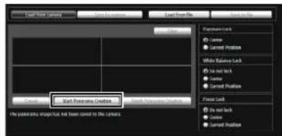
To stop the capture when underway, click [Cancel].

When you position the mouse pointer over the panorama image, a white grid is shown. If you want to recapture part of the panorama, position the pointer inside the grid, right-click and select [Recapture].

To recapture an entire panorama image, click [Start Panorama Creation] again.
![CANON VB-M720F - Click [Start Panorama Creation]. - 4](/content/2026/08/1575110/images/fa8bb15175fc5b9719959336634fcc70dcae0967789f6021b3633d88c6f7a1dc.jpg)
Note
- While a panorama image is being captured, the image stabilizer function is temporarily disabled.
- The following users will be disconnected while creating a panorama image.
- All users except for administrators
- Users not connected via RTP
- When a small value is entered for [Maximum Frame Rate: Video Transmission] under [Video] > [JPEG] in the Setting page, panorama capture is slowed down.
2 When the capture is complete, click [Finish Panorama Creation] if the image is satisfactory.
Saving/Deleting a Panorama Image on the Camera
How to Save
Click [Save to camera], and then click [OK] in the displayed dialog box.
The panorama image is saved to the camera.

How to Delete
1 To delete the panorama image saved to the camera, click [Clear].
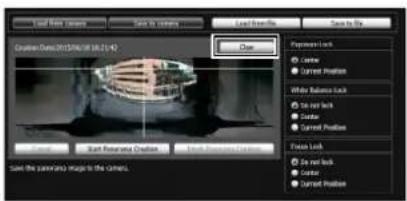
The image in the panorama video display area will be cleared.
2 Click [Save to camera], and then click [OK] in the displayed dialog box.
The panorama image saved in the camera is deleted.
Saving a Panorama Image as Image Files/ Opening from Image Files
You can save a recorded panorama image as an image file or open image files as a panorama image. Only JPEG image files created using Panorama Creation Tool can be handled.
How to Save
Click [Save to file] and then select the folder you want to save the image file in and enter the file name in the displayed dialog box.

How to Open from Image Files
Click [Load from file] and then select the image files you want to use in the displayed dialog box.

View Restriction Setting Tool is a tool that limits the range that can be captured by the camera. If view restrictions have been set, you can limit the displayable capture range using the viewer.


To limit zoom or a certain field of view when publishing live video, use the View Restriction Setting Tool to set the view restrictions easily.
[Apply View Restriction Setting]
Restrictions set by the View Restriction Setting Tool are applied in the following cases.
- When the Admin Viewer is accessed with authorized user authorities
- When the VB Viewer is accessed
- When accessed via the Intelligent Function Setting Tool
- When accessed via RM-Lite
Display Screens of View Restriction Setting Tool

(1) Video Display Area
The image currently captured by the camera is shown. Pan, tilt, and zoom operations are the same as in the Admin Viewer. For details, see "How to Operate the Viewer" (p. 139).
(2) [Switch Mouse Operation] button
Click the button to switch to 📊 in this mode, move the mouse pointer to the video display area and click to operate the pan and tilt. Click the button again to return to 🔒
(3) [Switch Screen Size] button
Each time this button is clicked, the screen size of the video display area switches between "480 x 270" and "960 x 540".
(4) [Obtain/Release Camera Control] button
This button is used to obtain/release the camera control privileges. For details, see "Obtaining Camera Control Privileges" (p. 141).
(5) [Control for Admin] button
Displays the Control for Admin Panel (p. 133).
(6) [Panorama Screen]
The panorama image registered in the camera is shown. View restriction preview frames, representing the view restriction setting values, are also shown. You can drag the frames to change their shapes, with the new settings being reflected in View Restriction Settings.
• View restriction preview frame
(6)-1 Pan/tilt preview frame (red frame)
Range of field of view defined by top/ bottom/left/right edges
(6)-2 Wide-angle preview frame (green frame)
Wide-angle restriction setting (restriction of capture frame)
(6)-3 Telephoto preview frame (yellow frame)
Telephoto restriction setting (restriction of maximum zoom ratio)
(7) [Digital Zoom]
The current digital zoom usage status of the camera is shown in real time.
(8) [Image Stabilizer]
The current image stabilizer usage status of the camera is shown in real time.
(9) [Apply the view restriction]
To use view restrictions, select this checkbox.
(10)View restriction setting entry boxes and [Get value]
You can enter a value in each view restriction setting entry box to change the applicable setting. You can load the values for the current camera angle to the view restriction settings by clicking [Get value].
• View restriction settings
[Upper Limit]: Top limit of the view restriction. Click [Get value] to load the top edge value of the current camera angle.
[Lower Limit]: Bottom limit of the view restriction. Click [Get value] to load the bottom edge value of the current camera angle.
[Left Limit]: Left limit of the view restriction. Click [Get value] to load the left edge value of the current camera angle.
[Right Limit]: Right limit of the view restriction. Click [Get value] to load the right edge value of the current camera angle.
[Telephoto]: Telephoto limit of the view restriction. Click [Get value] to load the zoom ratio of the current camera angle.
[Wide-angle]: Wide-angle limit of the view restriction. Click [Get value] to load the zoom ratio of the current camera angle.
(11)[Display in panorama screen]
Apply the current view restriction settings to the panorama screen. At this point, the settings are not yet saved in the camera. Be sure to click [Save settings].
Clear the settings you have specified on the screen of the tool and restore the settings saved in the camera.
(13)[Save settings]
Save the set view restriction in the camera.
After the view restriction has been set, be sure to save the settings in the camera by clicking [Save settings].
Setting View Restrictions
You can set view restrictions by entering values in the view restriction setting entry boxes, or by changing the current settings in the view restriction preview frame of the panorama screen or from the camera angle in the video display area. Select appropriate settings according to the environment in which the camera is operated or the purpose for which it is used.
■ Use the preview frame on the panorama image to set view restrictions.
1 Select the [Apply the view restriction] checkbox.

2 Drag to change the [Pan/tilt preview frame (red frame)], [Telephoto preview frame (yellow frame)], or [Wide-angle preview frame (green frame)] shown on the panorama screen to set view restrictions.
When the telephoto/wide-angle preview frames are enlarged/shrunk, the aspect ratio remains the same. At this time, you can also enter view restrictions by entering values in the view restriction setting entry boxes. If you have adjusted the view restriction settings, click [Display in panorama screen]. The settings are reflected in the preview frame of the panorama screen.
3 Click [Save settings].

Confirm that the settings have been applied correctly, and then click [Save settings] to save the settings in the camera.
■ Setting by Loading Position Information from Image in Video Display Area
1 Select the [Apply the view restriction] checkbox.
2 Click the [Obtain/Release Camera Control] button to obtain the control privileges of the camera.
3 Operate the camera to adjust the top edge, bottom edge, left edge, right edge, telephoto, or wide angle to desired positions, and click [Get value] each time.
The loaded view restriction can be checked in the view restriction setting entry box or view restriction preview frame.

4 Click [Save settings].
The settings are saved in the camera.
Important
- If you have changed the camera mounting method, recapture the panorama image and register it again.
- Check view restriction settings again if the [Video] > [Video Size Set] settings on the Setting page have been changed.
- The panorama screen may be slightly different from the actual image. After view restrictions have been set, be sure to confirm with the VB Viewer that the view restrictions have been reflected correctly.
- Confirm the settings using the VB Viewer. (View restrictions are not applied to the video display area of this tool, nor to the Admin Viewer.)
- If the image stabilizer or digital zoom setting has been changed, check the view restriction settings again.
Note
- Even when view restrictions are set, an area outside the view restriction may still appear momentarily when the camera is controlled near the boundary of the view restriction.
- To cancel the view restrictions, clear the [Apply the view restriction] checkbox and then click [Save settings].
- If the setting fields are cleared while the [Apply the view restriction] checkbox is selected, the maximum view restriction will be set.
- The controllable range and range that can be captured are as follows.

- The pan and tilt ranges vary depending on the zoom ratio (view angle).
Setting view restrictions automatically restricts the camera operating anglo.
When wide-angle is selected, the capture of the camera operating angle would exceed the view restrictions if it remained the same. Therefore, it is narrowed automatically.

- If the view restriction will be exceeded as a result of controlling the zoom toward the wide-angle side, the camera will first pan and tilt to a position where the maximum wide-angle zoom will be within the viewing restriction area. Wide-angle zoom control will then be enabled within the view restriction area.
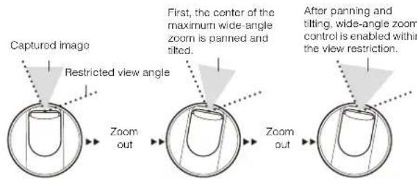
- Reducing the view restriction may also reduce the zoom range.
Preset Setting Tool
A tool that lets you set presets and the home position. You can make the desired settings with the mouse by referring to the preview in the panorama or full image mode. You can also set Preset Tour whereby the camera tours and monitors multiple presets.

![graph TD A["Reflecting in the viewer"] --> B["Executing preset tour"] B --> C["Building exterior view"] C --> D["Control Panel"] D --> E["Output: 100%"] style A fill:#f9f,stroke:#333 style B fill:#ccf,stroke:#333 style C fill:#cfc,stroke:#333 style D fill:#fcc,stroke:#333 style E fill:#ffc,stroke:#3…](/content/2026/08/1575110/images/b5014d1ac9f4d2b4f9fbf94aa4c77e96d29587e34012e6fc2153c457ebe38c36.jpg)
Important
H43 M42
- If you want to use intelligent functions, it is strongly recommended that you use the Preset Setting Tool to register a preset that corresponds to the camera position of the area where you want to use intelligent functions.
- When using presets registered in digital zoom range, the registered camera positions may not be reproduced with high accuracy. It is recommended that you use presets registered in the optical zoom range for preset tours and the Intelligent Function.
H630 H730 M620 M720
- Presets that were set with the Preset Setting Tool cannot be used for the settings of intelligent functions.
Display Screens of Preset Setting Tool
Preset Setting Tool has two display screens, the [Preset] tab and the [Preset Tour] tab.
With the [Preset] tab, up to 64 presets (VB-H43/VB-M42) presets and the home position are set while referring to the panorama screen or full image.
With the [Preset Tour] tab, Preset Tour is set whereby the camera tours and monitors multiple presets.
The following explains the [Preset] tab display screen.
For the [Preset Tour] tab, see "Preset Tour" (p. 111).
■ [Preset] Tab Display Screen


(1) Video Display Area
The image currently captured by the camera is shown.
Pan, tilt, and zoom operations are the same as in the Admin Viewer. For details, see "How to Operate the Viewer" (p. 139).
(2) [Switch Mouse Operation] button
Click the button to switch to 📋 in this mode, move the mouse pointer to the video display area and click to operate the pan and tilt. Click the button again to return to 🔒
(3) [Switch Screen Size] button
Each time this button is clicked, the screen size of the video display area switches between "480 x 270" and "960 x 540".
(4) [Obtain/Release Camera Control] button
This button is used to obtain/release the camera control privileges. For details, see "Obtaining Camera Control Privileges" (p. 141).
(5) [Control for Admin] button
Displays the Control for Admin Panel (p. 133).
(6) [Panorama Screen] H43 M42
The panorama image registered in the camera is shown. A preset preview frame (yellow) reflecting the preset settings is shown, where you can drag to resize or move the frame and reflect the new frame in the preset settings. Also, if view restrictions are set, those areas are shown in a blue frame.
(7) [Preset] tab, [Preset Tour] tab
Switch between the preset setting tab and preset tour setting tab.
(8) [Home Position/Preset] selection box
Select the preset or [home position] you want to set.
(9) [Quick Registration]
Load the current camera position, and register them as preset settings.
(10)[Preset Name]
You can enter a preset name of up to 64 characters. You can set a name in alphanumeric characters. Be sure to enter a single-byte alphanumeric preset name. When the [Home Position] is selected in (8), the preset name function is grayed out.
In a [Preset Name], ASCII characters (spaces or printable characters) can be used.
(11)[Detailed Settings] H43 M42
Show the detailed settings.
(11)-1 [Show in viewers] checkbox H43 M42
Select this checkbox to use presets in the viewer. When the [Home Position] is selected in (8), this function is grayed out.
(11)-2 Camera Parameter H43 M42
Enter the center angle of the desired angle in [Pan] and [Tilt]. In [Zoom], enter the view angle.
- Camera Angle
[Pan] ..... Set the pan position of the camera. [Tilt] ..... Set the tilt position of the camera. [Zoom] .. Set the viewing angle of the camera.
• [BLC] (Back Light Compensation)
Select [OFF] or [ON] for the BLC setting of the camera. The display is grayed out if [Smart Shade Control] is set to [Auto].
• [ Smart Shade Control]
Select [OFF], a level from [1] (Mild) to [7] (Strong) or [Auto] for the smart shade control setting of the camera. (p. 152)
• [Haze Compensation]
Select [Disable], one of 7 levels from [1] (Mild) to [7] (Strong), or [Auto] for the haze compensation of the camera. (p. 152)
• [Focus Mode]
Select [Auto], [Manual], or [Fixed at infinity] for the focus mode of the camera. (p. 153)
- [White Balance]
Set the white balance of the camera to [Auto] or according to the light source of the condition in which it is used. For details on light sources, see p. 57.
• [R Gain], [B Gain]
If white balance is set to [Manual], set the respective gains to a value between 0 and 1023.
(12)[Get camera info] H43 M42
Load the current camera angle and other settings of the video display area to reflect them in the panorama screen and camera parameter settings.
(13)[Full Image] H630 H730 M620 M720
Displays the full image obtained from the camera. A preset preview frame (yellow) reflecting the preset settings is shown. If you drag to resize or move the frame, the new frame is reflected in the preset settings.
(14)[Update Image] H630 H730 M620 M720
Load the full video from the current camera to update the video.
(15)[Show in viewers] checkbox
H630 H730 M620 M720
Select this checkbox to use presets in the viewer. When home position is selected in (8), this function is grayed out.
(16)Camera Parameters H630 H730 M620 M720
Displays the values for the pan and tilt positions and zoom viewing angle in accordance with the size and position of the preset preview frame on [Full Image].
(17)[Get Digital PTZ Info] H630 H730 M620 M720
Load the current crop position of the video display area to reflect it in the preset preview frame in [Full Image] and the camera parameters.
(18)[Preview settings]
Preview the image with the camera parameter values that are being edited in the video display area.
(19)[Clear settings]
Delete the settings for the preset selected.
Clear the settings you have specified on the screen of the tool and restore the settings saved in the camera.
(21)[Save settings]
Save the edited preset settings in the camera. If presets have been set, be sure to save the settings by clicking [Save settings].
Setting the Preset
Select presets or home position as needed for the operating environment or desired objectives. A preset can be set in the following ways.

Note
The number of presets you can register are as follows.
- Maximum 642
- H630 H730 M620 M720 Maximum 20
■ Setting from Camera Angle in the Video Display Area
1 Select the preset you want to set from the [Home Position/Preset] selection box, and then fill the [Preset Name] field.
Be sure to enter the preset name.

2 Click the [Obtain/Release Camera Control] button to obtain the control privileges of the camera.

3 Operate the camera from the video display area, set it to the desired position and click [Quick Registration].
■ Use the preview frame of the panorama screen to set presets H43 M42
Use the preview frame of the panorama screen to set presets.
1 Select the preset you want to set from the [Home Position/Preset] selection box, and then fill the [Preset Name] field.
Be sure to enter the preset name.

2 Click [Detailed Settings] and select the [Show in viewers] checkbox.

3 Drag to move or resize the preset preview frame (yellow) shown on the panorama screen to set the preset.

If you click on the panorama screen, the preview frame will move to center on the clicked point.
4 Click [Preview settings].
The settings are reflected in the video display area. If you previewed incorrect settings, etc., and want to restore the settings registered in the camera, click [Restore settings].
5 Click [Save settings].
■ Using the Digital PTZ Function to Set Presets
H630 H730 M620 M720
Use the Digital PTZ function to set part of the area that can be captured by the camera as a preset.
1 Select the preset you want to set from the [Home Position/Preset] selection box, and then fill in the [Preset Name] field.
Be sure to enter the preset name.

2 Select the [Show in viewers] checkbox.

3 Change the position or size of the preset preview frame (yellow) displayed on [Full Image] to set the preset position.
If you click on the full video, the preview frame will move to center on the clicked position.

4 Click [Preview settings].
The settings are reflected in the video display area. If you previewed incorrect settings, etc., and want to restore the settings registered in the camera, click [Restore settings].
5 Click [Save settings].
![CANON VB-M720F - Select the preset you want to set from the [Home Position/Preset] selection box, and then fill the [Preset Name] field. - 9](/content/2026/08/1575110/images/c6883060a87e1f72f4ba999862060bf6ce9fa7f318c25f5adab6358159b9441b.jpg)
Note
Digital PTZ is a function for transmitting only the specified part of a camera video. Therefore, this function reduces the load on the network.
■ Specifying Detailed Settings
H43 M42
If you want to fine-tune the camera angle or to adjust the image, etc., click [Detailed Settings] and specify the detailed settings before saving the preset settings in the camera.
1 Select the [Show in viewers] checkbox.

2 Click [Get camera info].
The camera parameters in the video display area are loaded to [Detailed Settings].
3 Fine-tune the camera angle and adjust the image quality with focus or smart shade control while checking the image.
4 Click [Preview settings].
The settings are reflected in the preview frame on the panorama screen and the video display area. If you previewed incorrect settings, etc., and want to restore the settings registered in the camera, click [Restore settings].
5 Click [Save settings].

Important
- To use presets in the viewer, select the [Show in viewers] checkbox.
- Set presets again if the camera mounting conditions have been changed.
- Check preset settings again if the [Video] > [Video Size Set] settings on the Setting page have been changed.
- If [Manual] is selected in [Focus Mode], manually adjust the focus while checking the actual image in the video display area. After the focus has been adjusted, set the focus using [Get camera info]. Click [Save settings] to save the focus settings.
- If the image stabilizer setting is changed after a preset has been set, the viewing angle during operation will no longer agree with the viewing angle at the time the preset was set (p. 58). Check the preset settings again if the image stabilizer setting is changed.
- If a dome housing is used, be sure to set presets with the dome installed.

Note
- Changes to preset settings are not reflected in already connected viewers.
- You can disable presets in the viewer by clearing the [Show in viewers] checkbox under [Detailed settings].
- The [BLC] is not available if [Smart Shade Control] is set to [Auto].
- If you set [Smart Shade Control] to [Auto] or [1] to [7], [Haze Compensation] is set to [Disable].
- If you set [Haze Compensation] to [Auto] or [1] to [7], [Smart Shade Control] is set to [Disable].
Preset Tour
Set a preset tour whereby the camera tours and monitors the multiple presets currently set.
■ [Preset Tour] Tab Display Screen
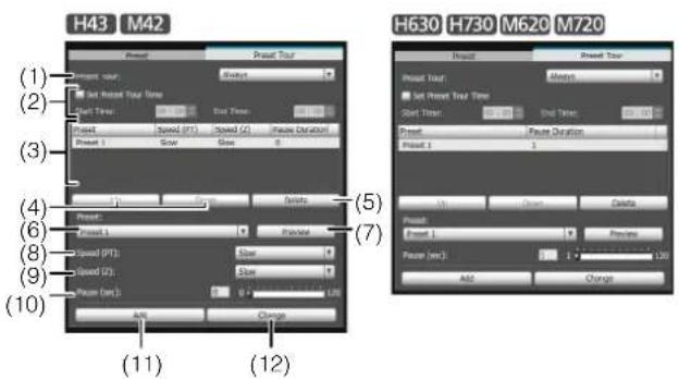
(1) [Preset Tour] selection box.
Select when you want to perform a preset tour from the following options.
[Not used]
Preset tour is not performed.
[For Viewers]
Preset tour is performed when a camera is connected via the VB Viewer, etc.
[Always]
Preset tour is always performed.
(2) [Set Preset Tour Time] checkbox
This setting is enabled when [For Viewers] or [Always] is selected in (1). Select the checkbox to configure a preset tour at a predetermined time, and enter the start time and stop time for the preset tour.
(3) Tour schedule list
A list of presets set for preset tour.
(4) [Up] / [Down]
Select preset in the list and click [Up] or [Down] to change sequence of the tour schedule list. Presets tours are performed in order from the top of the list.
(5) [Delete]
Delete the preset selected from the tour schedule list.
(6) [Preset] selection box
Select the preset you want to add to the tour schedule list.
(7) [Preview]
The camera switches to the camera angle selected in [Preset], and the new angle can be checked in the video display area.
(8) [Speed (PT)] H43 M42
Select [Slow], [Normal], or [Fast] for the moving speed of the camera during panning/tilting.
(9) [Speed (Z)] H43 M42
Select [Slow] or [Fast] for the camera speed during zoom.
(10)[Pause (sec)]
Set the time at which the camera stops at the preset position.
H43 M42
You can set between 0 and 120 seconds in 5-second increments.
H630 H730 M620 M720
You can set between 1 and 120 seconds in 1-second increments.
(11)[Add]
Add the preset to the tour schedule list.
(12)[Change]
Change the speed or pause time between presets selected from the tour schedule list.
![CANON VB-M720F - ■ [Preset Tour] Tab Display Screen - 2](/content/2026/08/1575110/images/57a8c6ab7a494aed5904165120b87059e63330b0c129a2dd84d3e03bf9197ee4.jpg)
Note
- Preset tour is not performed while the camera is being controlled with viewers, Admin Tools, etc.
- Preset tour is not performed when control privileges are obtained by RM-Lite.
■ Setting the Preset Tour
1 Select the touring method from the [Preset Tour] selection box.
Select [For Viewers] or [Always].

Setting the preset tour time
Select the [Set Preset Tour Time] checkbox.
Enter values for [Start Time] and [End Time] to set the preset tour time.
2 Select the preset number you want to add to the tour schedule from the [Preset] selection box, and then click [Add].
The preset is registered in the tour schedule list. Up to 20 presets can be registered.

3 Select a preset in the tour schedule list, and set the preset operation.
H43 M42
In [Speed (PT)] and [Speed (Z)], you can set the pan, tilt, and zoom speeds of the preset.

In [Pause (sec)], you can enter the number of seconds for the camera to remain stationary at the preset position.
When [Preview] is clicked, the camera angle switches to this preset, and the new angle can be checked in the video display area.
4 Click [Change].
When you want to delete changes made to the tour schedule list and restore the settings registered in the camera, click [Restore settings].
5 Click [Save settings].
When you complete setting the tour schedule list, click [Save settings]. The settings are saved in the camera.

Important H43 M42
If preset tour is used, do not use the intelligent function.

Note
The home position cannot be added to the tour schedule list.
Intelligent Function Setting Tool
This tool is used to set intelligent functions that perform uploads, notify the viewer, audio playback, etc., if a change has occurred in the captured image due to movement of a subject.
![graph TD A["Camera Tampering Detection"] --> B["Volume Detection"] B --> C["Passing Detection"] C --> D["Abandoned Object Detection"] D --> E["Removed Object Detection"] F["Camera"] --> G["Network"] H["E-mail notification"] --> I["Admin Viewer RM Viewer"] I --> J["Upload to FTP server/HTTP server"]…](/content/2026/08/1575110/images/0f405d9d170de5f34969c45663db027b14e11cf08706346dc7de6488613910c7.jpg)
The intelligent functions can perform the following 6 types of detection. Use detection types that best serve your needs.
Moving Object Detection
Detect moving objects. This function can be used to detect visitors or suspicious individuals. Moving object detection is triggered when moving objects are inside the detection area.
![graph LR A["Background Image Generated"] --> B{Change in Designated Area Analysis} B --> C["Moving Object Detected"] D["Detection begins when a moving object enters the designated area."] --> E["Moving object enters/leaves area."] E --> F["Detected"]](/content/2026/08/1575110/images/ace2c429a3cac6f1081670837f9477fe95a92b16a30ff3f9030d165bfef5a913.jpg)
Abandoned Object Detection
Detect objects that are carried in and abandoned for a certain amount of time. This function can be used to detect objects that have been left.
Abandoned object detection is triggered when an object is left in the detection area for a specified duration.
![graph LR A["Background Image Generated"] --> B{Change in Designated Area Analysis Abandoned Object Detected} B --> C["Object abandoned."] C --> D["Detected"]](/content/2026/08/1575110/images/8d1a41fcb9d1366719fe5896a28d1ce9548c7d9504d76ea7cdcab733037441e5.jpg)
Removed Object Detection
Detect objects that are being removed. This function can be used to detect actions such as taking away valuables.
Removed object detection is triggered when an object is removed from the detection area for a specified duration.
![graph LR A["Background Image Generated"] --> B["Change in Designated Area Analysis Object Removal Detected"] B --> C["Removing an object."] C --> D["Detected"]](/content/2026/08/1575110/images/e9450c89b3f7e258ece0ea0d2f333c609ad31fbbd63901baf7e47001eab7036a.jpg)
Camera Tampering Detection
Detect when the capture is being obstructed. This function can be used to detect when the camera orientation is changed or the image display is obstructed with spray, etc.
Camera tampering detection is triggered when an area exceeding the set ratio of change is continuously altered by an object, etc.
![graph LR A["Detection begins when the ratio of change in a video exceeds a set amount."] --> B["Image generation"] B --> C["Tampering detected."] C --> D["Detected"]](/content/2026/08/1575110/images/861c432a59623136e9b289bf2a37b96a936521125e81b21dab325bce110e41d5.jpg)
Passing Detection
Detect when a person or moving object crosses a specified line.
It determines that an object is passing when the decision point of the object detection frame crosses a detection line.
![graph LR A["Detection begins when the decision point crosses the specified detection line."] --> B["Passing detected."] B --> C["Detected"] style A fill:#f9f,stroke:#333 style B fill:#ccf,stroke:#333 style C fill:#cfc,stroke:#333](/content/2026/08/1575110/images/ae45bf6708a5d5c60d054f09145b86171db0f6aacee62ceac1a80bd7da011eff.jpg)
Volume Detection
Detect specified volume levels. For setting details, see "Chapter 4 Setting Page" [Event] > [Volume Detection] (p. 71).
Caution
Notes on Use of This Camera
The intelligent functions are not suitable for applications where high reliability is required. If constant and maximum reliability is required for surveillance it is not recommended that you use this function. Canon shall assume no liability for any accident, loss or other undesirable outcomes resulting from intelligent function operations.

(1) Video Display Area
The image currently captured by the camera is shown. Detection areas are shown in translucently colored frames (rectangular or polygonal) and the detection line is shown as a translucently colored polygonal line or line segment. Also, subjects for which movement has been detected are shown in a detection block and detection frame.
H43 M42
Pan, tilt, and zoom operations are the same as in the Admin Viewer. For details, see "How to Operate the Viewer" (p. 139).
However, when the (11) [Lock camera position] checkbox is selected, the camera is fixed at a preset position and cannot perform pan, tilt, and zoom operations.
(2) [Switch Mouse Operation] button H43 M42
Each time this button is clicked, the button switches between and , and the mouse operation in the video display area changes.
When the button is set to detection areas can be created/resized/moved. While in this mode, the camera orientation will not change.
When the button is set to + and the (11) [Lock camera position] checkbox is not selected, pan, tilt, and zoom operations can be performed.
(3) [Switch Screen Size] button
Each time this button is clicked, the screen size of the video display area switches between "480 x 270" and "960 x 540".
(4) [BLC] button
This button turns on/off backlight compensation. This control is effective when the image is dark due to backlight.
(5) [Obtain/Release Camera Control] button
This button is used to obtain/release the camera control privileges. For details, see "Obtaining Camera Control Privileges" (p. 141). If camera control privileges have not yet been obtained elsewhere, such as in the Admin Viewer, the control privileges will be obtained the moment the Intelligent Function Setting Tool is launched.
(6) [Control for Admin] button
Show the Control for Admin Panel (p. 133).
(7) [Event Display] button
Show the event display panel (p. 124).
(8) [Display Options]
Select the [Detection Area/Line] or [Detection Results] you want to show in the video display area from the following items.
• [Selected Detection Settings Only]
Show the detection areas/lines or detection results only for those detection settings selected in the [Detection Setting List].
• [All Detection Settings]
Show the detection areas/lines or detection results for all detection settings in the [Detection Setting List].
• [Detection Settings of the Same Type]
Show the detection areas/lines or detection results for the same type of detection settings as those selected in the [Detection Setting List].
- [Do not display]
No detection areas/lines or detection results are shown.
(9) [Restart intelligent function]
If the background image has changed while you were specifying settings or detection results are not as set, etc., click this button to restart the intelligent function.
If camera control privileges are not obtained, this function is grayed out.
![CANON VB-M720F - [Restart intelligent function] - 1](/content/2026/08/1575110/images/9d53305b6e8e1a0d0e2a24a29c931e1befef3f07e9484331f3d3bb44344e2f0d.jpg)
Important
It takes tens of seconds for the intelligent function to restart. No detection is performed while restarting.
(10)[Detection Settings]
Show the [Detection Settings] dialog box (p. 124). This dialog box allows you to reduce the effects of lighting changes.
(11)[Lock camera position] checkbox H43 M42
Select this checkbox to move the camera position to a preset position selected from the preset selection box and lock it there. Lock the camera position when specifying detection settings to obtain a correct detection result. If camera control privileges are not obtained or a preset position has not been set, this function is grayed out.
(12)Camera position selection box H43 M42
Select the camera position from the view restriction presets or the home position. Use the Preset Setting Tool to set presets or the home position (p. 106). If camera control privileges are not obtained, the [Lock camera position] checkbox is not selected, or a preset position within the view restriction has not been set, this function is grayed out.
(13)[Detection Setting List]
A list with the specified detection settings is shown.
(14)[Add]
The [New Detection Settings] dialog box is shown and detection settings can be added.
(15)[Delete]
Delete detection settings selected from the [Detection Setting List].
(16)[Detection Setting Number], [Detection Type]
The detection setting numbers and detection types selected from the [Detection Setting List] are shown.
(17)[Enable these detection settings] checkbox
Select this checkbox to enable the detection settings that are selected in the [Detection Setting List].
(18)[Detection Criteria] tab, [Event] tab
Switch between the Detection Criteria and Event tabs.
• [Detection Criteria]
Specify detection settings name, detection area/line, and detection criteria (p. 119).
• [ Event ]
Specify operations to be performed when events occur (p. 120).
Clear the settings you have specified on the screen of the tool and restore the settings saved in the camera.
(20)[Save settings]
Save the edited detection settings in the camera. After the detection settings have been specified, be sure to save the settings in the camera by clicking [Save settings].
Flow of Intelligent Function Setting
The intelligent functions are set according to the procedure below. For details on the setting method, see each setting page.

Important H630 H730 M620 M720
Presets that were set with the Preset Setting Tool cannot be used for the settings of intelligent functions.
■ Camera Position Settings
H43
M42
1 Register the camera angle as a preset using the Preset Setting Tool.
For details on the preset setting method, see "Preset Setting Tool" (p. 106).
Important
It is strongly recommended that you preset the camera angle in advance and lock the camera at a preset position with the Intelligent Function Setting Tool. An angle of view that captures the target object up close is also recommended.
2 Launch the Intelligent Function Setting Tool.
3 Click [Yes].

This selects [Lock camera position] in the Intelligent Function Setting Tool. If [No] is clicked, select [Lock camera position].
![CANON VB-M720F - Click [Yes]. - 2](/content/2026/08/1575110/images/6f5dfc78200ae1d0d95c48ceb52cf55b4a787259d2c35599cdec1eca3e7dce6e.jpg)
4 Select a preset.
■ Intelligent Function Settings
1 Add detection settings.
When you click [Add] in the [Detection Setting List], the [New Detection Settings] dialog box is displayed. Set the [Detection Setting Number] and [Detection Type] of the detection setting you want to add, and then click [OK].
Up to 15 different detection settings can be registered.
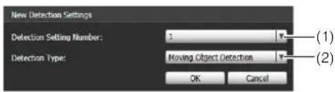
(1) [Detection Setting Number]
Specify a detection setting number from 1 to 15 for the detection area you want to set.
(2) [Detection Type]
Select detection types that suit your purpose from [Moving Object Detection], [Abandoned Object Detection], [Removed Object Detection], [Camera Tampering Detection], or [Passing Detection]. For details on detection types, see p. 113.
2 Enable Detection Settings.
To enable detection settings, select [Enable these detection settings].
Clear this checkbox to disable a setting.

3 Set detection criteria ([Detection Criteria] tab p. 119).
Set detection criteria while operating the camera and checking the image in the video display area.
4 Set operations to be performed when a change in a subject is detected ([Event] tab p. 120).
Set e-mail notification, video record, and audio playback to be performed upon detection.
5 Save the detection settings in the camera.
Click [Save settings] to save the settings in the camera.
6 Check the detection result.
You can check the detection status of the specified detection settings in the event display panel (p. 158).
Important
Notes on intelligent function settings and operation
- When setting intelligent function, do an actual detection test to confirm that detection will be performed correctly.
- When the entire screen are exposed to sudden changes in brightness, detection may not be performed as intended for up to 5 minutes.
- If the display switches between Day mode and Night mode, [Restarting intelligent function. Please wait.] is shown and intelligent function will restart. Detection will not be performed while intelligent function is restarting.
- If the camera is operated during intelligent function setting or operation, [Restarting intelligent function. Please wait.] is shown and intelligent function will restart. Detection will not be performed while intelligent function is restarting.
- If [Video] > [Video Size Set] on the Setting page is changed, be sure to change the preset position setting (VB-H43/VB-M42 only) and intelligent function settings, and check the operation. The intelligent function may not operate, depending on the settings.
H43 M42
- Set intelligent function again if the angle of view is changed through camera operation, or the camera position of a preset or home position is changed using Preset Setting Tool.
- If [Status] in [Detection Setting List] is [Enabled] when the camera position is fixed, control privileges cannot be obtained by VB Viewer or RM Viewer. Also, the preset tour and auto control of custom settings will no longer run.
- When using presets registered in digital zoom range, the registered camera positions may not be reproduced with high accuracy. It is recommended that you use presets registered in the optical zoom range for the Intelligent Function.
Difficult-to-detect Subjects
- Objects or portions where there is little contrast in color or brightness with the background may not be detected.
- Small objects and changes on the screen may not be detected.
- Partial or entire changes in light on the screen may trigger detection.
- If multiple objects overlap, the detection status may change. In particular, passing may not be detected or may be detected at the wrong timing.
Setting Intelligent Function Detection Settings
■ Setting Detection Criteria ([Detection Criteria] tab)
Set detection criteria while operating the camera and checking the image in the video display area.
[Detection Criteria] tab
Moving object detection, abandoned object detection, camera tampering detection

Removed object detection

Passing detection

Video Display Area

(1) [Detection Settings Name]
You can use up to 64 characters in a detection setting name. Be sure to enter a single-byte alphanumeric detection setting name.
In a [Detection Settings Name], ASCII characters (spaces or printable characters) can be used.
(2) [Area Shape]
Select [Rectangular] or [Polygonal] for the shape of detection areas you want to set in the video display area.
[Quick setting]
The detection area is drawn automatically when the detection criteria is [Removed Object Detection].
For details on detection area setting operations, see "Setting Detection Areas" (p. 120).
[Clear]
If the [Area Shape] is [Polygonal], the detection area set in the video display area is deleted.
(3) [Display Color]
Choose the color of the detection setting. The color selected here becomes the display color of the detection area/line in the video display area.
(4) [Object Size (%)] [Change Ratio (%)] [Duration (Sec)]
Set the lower limit for the size, change ratio, and judgment time for the set detection area to trigger detection. If the value set here is exceeded, "Detected" mode is triggered.
Click the text box to enter a value directly, or specify a value using the slider.
For details on the setting method, see "Setting Detection Criteria per Detection Type" (p. 121).
(5) [Clear detection line]
Clears the detection line set in the video display area.
(6) [Passing Direction]
Select the passing direction of a moving object relative to the detection line.
(7) [Decision point]
Select the point of a moving object that will be used as criteria for passing detection when a moving object crosses a detection line.
![CANON VB-M720F - [Decision point] - 1](/content/2026/08/1575110/images/11a1037909f32b36e536087a7728305f8d7ae9c300f4068f4e7bf5d947d51591.jpg)
Important
It is recommended that the detection criteria are set in a condition as close as possible to the condition in which the camera is actually used. Perform a detection test in advance to make sure that the detection frame continues to be displayed for a subject targeted for passing detection.
■ Setting Event Operations ([Event] tab)
Set operations to be performed upon detection of changes in a subject.
[Event] tab

(1) Specify the operation timing. (Multiple checkboxes can be selected.)
[ON Event Operation] checkbox
When selected, the operations set in (2) [E-mail Notification] and [Video Record] are performed the moment detected mode is triggered to ON.
[OFF Event Operation] checkbox
When selected, the operations set in (2) [E-mail Notification] and [Video Record] are performed the moment detected mode is triggered to OFF.
[Detected mode Operation] checkbox
When selected, the operations set in (2) [E-mail Notification] and [Video Record] are performed for as long as detected mode is active.
(2) Specify the event operation. (Multiple checkboxes can be selected.)
[E-mail Notification] checkbox
When selected, e-mail notification is performed at the timing set in (1). [E-mail Notification] must be set in advance under [Upload] in the Setting page(p. 68).
[Video Record] checkbox
When selected, video record is performed at the timing set in (1). [Video Record Action] must be set in advance under [Event] in the Setting page (p. 71).
(3) Specify the audio playback timing.
[Audio Playback at ON Event] checkbox
When selected, the sound set in (4) [Sound Clip Name] is played at the moment the detected mode is triggered to ON.
[Audio Playback at OFF Event] checkbox
When selected, the sound set in (4) [Sound Clip Name] is played at the moment the detected mode is turned OFF.
(4) Set the playback sound.
[Sound Clip Name]
Select the sound that is to be played. The sound clip name set for [Sound Clip Upload] under [Event] in the Setting page is shown in the pull-down list (p. 74).
[Volume]
Set the audio playback volume in the range of 1 to 100.
(5) Operation of External Device Output
[External Device Output for ON Event] checkbox
Select this checkbox for enabling external device output at an ON event and select output destination (output 1 or 2) and operation (active or inactive).
[External Device Output for OFF Event] checkbox
Select this checkbox for enabling external device output at an OFF event and select output destination (output 1 or 2) and operation (active or inactive).
■ Setting Detection Areas
Set detection areas in the video display area.

Setting a [Rectangular] detection area
By default, a rectangle is shown in the video display area. Move or resize that rectangle to set a detection area.

Setting a [Polygonal] detection area
Specify polygonal areas with a maximum of 32 angles. Click in the video display area to form the polygon point by point. Click on a previously set point to complete the polygon and set the enclosed area as the detection area. The set area can also be moved by dragging it.
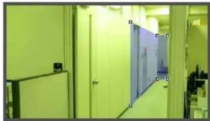
Setting a detection area using [Quick setting]
[Quick setting] can be configured for [Removed Object Detection] only.

1 Temporarily remove the object whose removal you want to detect from the video display area.
2 Click [Restart intelligent function]. The background video is created.
3 Replace the object whose removal you want to detect in its original position.
4 Click [Quick setting].
An outline for the detection object is drawn using a polygon with up to 32 points.
If there are multiple detection objects, the area is drawn around the largest object.

5 Click [Restart intelligent function] again.
![CANON VB-M720F - Setting a detection area using [Quick setting] - 3](/content/2026/08/1575110/images/eb6f1ccbb9d1ff7aef89634ae5459ed360372c1d771a3024db5415c7e81dcb53.jpg)
Note
- Drag the square marks (■) at each angle to change the shape of the polygon.
- Click [Clear] to delete the polygonal detection area.
• The camera tampering detection area cannot be changed.
Changing a [Rectangular] detection area into a [Polygonal] shape or changing a [Polygonal] detection area into a [Rectangular] shape
Changing the shape of the detection areas already set deletes that area and switches to a new drawing setting.
■ Setting the Detection Line
Use the video display area to set the detection line.
Specify a detection line consisting of a polygonal line with a maximum of 32 angles.
In the video display area, click the start point of the detection line and then click the end point. To create a detection line consisting of polygonal line, click each angle in the polygonal line in order.
To confirm a detection line, click any of the already set angles.
The angles in a confirmed detection line can be dragged to change the shape of a detection line and lines between angles can be dragged to change the position of the detection line.


Note
- Drag the square marks (■) at each angle to change the shape of the detection line.
- Click [Clear detection line] to delete a detection line.
■ Setting Detection Criteria per Detection Type
Specify different detection criteria for each detection type.
Detect criteria for [Moving Object Detection]
Set detection areas where you want to detect moving objects.
![CANON VB-M720F - Detect criteria for [Moving Object Detection] - 1](/content/2026/08/1575110/images/613235c3df64e0cf382e673908c4906cd8a58f5d30e07caa10426716eedd6ca0.jpg)
For [Object Size (%)], enter a value or move the slider to set the ratio of the size of an object moving in the detection area to the size of the detection area.
When the ratio of an area where the camera has detected a moving object exceeds the value set for [Object Size (%)], detected mode is triggered to ON.
When [Object Size (%)] is changed, an indicator frame showing the size of the object is displayed for 1 second in the center of the video display area, allowing specification of the settings while checking the size ratio.

Detection area
-Object size indicator
Any moving objects detected are shown with contour lines. If a moving object is smaller than [Object Size (%)], its contour lines are white. If the moving object is larger than [Object Size (%)], its contour lines take on the same color as the detection area, indicating that "detection" mode has been triggered to ON.

Contour lines of a detected moving object
![CANON VB-M720F - Detect criteria for [Moving Object Detection] - 4](/content/2026/08/1575110/images/fa556c439fb0225c3a8bb4a24a3e64f61a2a66e15863b8dffd1540aa86dfa05e.jpg)
Note
If an object is placed in or removed from the moving object detection area, "detected" mode will be triggered for Moving Object Detection.
Detect criteria for [Abandoned Object Detection]
Set areas where you want to detect abandoned objects as detection areas.

[Object Size (%)]
Enter a value or move the slider to set the ratio of the size of an object that was left behind in the detection area to the size of the detection area.
When [Object Size (%)] is changed, an indicator frame representing the area of the object is displayed for 1 second in the center of the video display area. This allows you to check the size ratio of the abandoned object detection area while specifying the [Object Size (%)] setting.
[Duration (Sec)]
Set the time that must elapse after an object has been left.
If both the values for [Object Size (%)] and [Duration (Sec)] are exceeded, detection mode is triggered to ON.

Any moving objects detected are shown with contour lines. If [Object Size (%)] and [Duration (Sec)] are not exceeded, contour lines are white. When all detection criteria are met, contour lines take on the same color as the detection area and "detected" mode is triggered to ON.

Detect criteria for [Removed Object Detection]
Set detection areas for objects whose removal you want to detect. If there are multiple objects for which you want to enable detection, be sure to configure Removed Object Detection for each object.
![CANON VB-M720F - Detect criteria for [Removed Object Detection] - 1](/content/2026/08/1575110/images/241be7d52f06adabcd178666bc114f74ae6f359de5a08f7aaff3da90e52b0e6c.jpg)
For [Duration (Sec)], set the time that must elapse after the object has been taken away. Detected mode will be triggered to ON when an object is taken away from the detection area for a period longer than the set [Duration (Sec)].

Any moving objects detected are shown with contour lines. As long as [Duration (Sec)] has not elapsed, contour lines are white. When [Duration (Sec)] has elapsed, contour lines take on the same color as the detection area, indicating that "detected" mode has been triggered to ON.

![CANON VB-M720F - Detect criteria for [Removed Object Detection] - 4](/content/2026/08/1575110/images/fda200da128587d3ca81e28077dfbd3be563060e749e31c87d59f6bce8144e49.jpg)
Important
Set detection areas for removed object detection so that they precisely match the contours of the object in question. Influence from the target object's shadow or adjacent objects may result in the target object being recognized as larger than actual and will not trigger Removed Object Detection. In such cases, reconfigure the detection area to outline the recognized target object. Alternatively, use [Quick setting] (p. 121).
Detect criteria for [Camera Tampering Detection]
For [Camera Tampering Detection], the entire video display area becomes the detection area. Detected mode will be triggered to ON when the video changes over an area exceeding the ratio set in [Change Ratio (%)].
![CANON VB-M720F - Detect criteria for [Camera Tampering Detection] - 1](/content/2026/08/1575110/images/60be768779c5acbba3826fca5c9fa17bff0f73301205d348ee1241726be153f4.jpg)
When [Change Ratio (%)] is changed, an indicator frame representing the percentage of the entire video display area is displayed for 1 second in the center of the area, allowing you to check while specifying the setting.

Any moving objects detected are shown with contour lines. If it is smaller than [Change Ratio (%)], contour lines are white. If the image is changed for an area larger than [Change Ratio (%)], contour lines take on the same color as the detection area, indicating that "detected" mode has been triggered to ON.

![CANON VB-M720F - Detect criteria for [Camera Tampering Detection] - 4](/content/2026/08/1575110/images/1fc33d089e3fdd003983a3085e4fbfa115aaa59325a4a2e20222651cf5f8826e.jpg)
Note
Detection will not be possible for three seconds after the change ratio is modified when camera tampering detection is selected, or when switching into camera tampering detection from another detection mode.
Detect criteria for [Passing Detection]
Set the passing direction and decision point of the moving object for the detection line that the moving object will cross.

[Passing Direction]
Select the direction for moving objects to pass the detection line. When an object that moves in the selected direction passes the detection line, "line crossed" is detected.
A preview display shows the selected passing direction on the detection line in the video display area.
[Decision Point]
Select the decision point of a moving object in accordance with a detection line. When a decision point selected here crosses the detection line, "line crossed" is detected. In the video display area, a cross mark is displayed to indicate the decision point in the detection frame.

[Object Size (%)]
Enter or use the slider to set the size ratio of moving objects for the entire screen.
When a moving object exceeds the value set for [Object Size (%)], it becomes a passing detection target.
When [Object Size (%)] is changed, an indicator frame showing the size of the object is displayed for 1 second in the center of the video display area, allowing specification of the settings while checking the size ratio.

![CANON VB-M720F - [Object Size (%)] - 2](/content/2026/08/1575110/images/caab14bbb367c8bfa59ce25af4f4d5679d08e971ec4bf38c4a4ef85d2cb5ddfd.jpg)
Important
Perform a detection test in advance to make sure that the detection frame continues to be displayed for a subject targeted for passing detection.

Note
- A ratio of up to 30% can be set for [Object Size (%)] in passing detection.
- A passing detection event is notified only when the decision line is crossed. Take care in setting the operation to be performed when an event occurs.
■ Setting by Right-Click Menu
Right-click on the Intelligent Function Setting Tool display screen to display the menu. There, the following functions can be used.
[Copy detection area/line]
Copy the detection area/line of the detection setting selected.
[Paste detection area/line]
Paste the copied detection area/line to the detection setting selected. It cannot be copied to camera tampering detection. Pasting a detection line is possible only when the source and the target both set passing detection.
[Clear detection area/line]
Clear the detection area/line of the detection setting selected. It cannot be cleared in camera tampering detection.
[Copy detection criteria settings]
Copy the detection criteria of the detection setting selected.
[Paste detection criteria settings]
Paste the copied detection criteria to the detection setting selected. Pasting is possible only if the source and the target are the same detection type.
[Copy event settings]
Copy the event operations of the detection setting selected.
[Paste event settings]
Paste the copied event operations to the detection setting selected.
■ Reducing effects of lighting change
Intelligent functions may not work when the entire screen is exposed to sudden changes in brightness, for example, when indoor lights are turned on or off. Changing the detection settings may reduce this effect.
1 Click [Detection Settings].
2 Select [Reduce effects of lighting change].

3 Click [Save settings].

Important
A [Reduce effects of lighting change] setting may not work depending on the operating environment. Sudden changes in brightness that persist may also have the same effect. Perform a detection test to check what will work.

Note
Since changing [Detection Settings] restarts the intelligent functions, detection will not be performed during the tens of seconds that it takes to complete a restart.
■ Displaying Event Status
Click the [Event Display] button to open the event display panel and confirm the detection status icon of the intelligent functions.

This panel displays the same information as [Intelligent Function (Image Detection)] in the event display panel of the Admin Viewer. For details, see "Displaying Event Status" (p. 158).

Note
If the detection setting is not stored in the camera, only the detection status for the currently selected detection setting is displayed.
Log Viewer
This tool lets you view the operating condition log of the camera.
Display Screens of Log Viewer

(1) [Download]
Download log files from this camera or memory cards.
(2) [Reload]
Reload the displayed log file and show the latest logs.
(3) [Previous File]
If there are multiple log files in the camera's internal memory or memory card, load and display the file before the currently shown log list.
(4) [Next File]
If there are multiple log files in the internal memory or memory card, load and display the file after the currently shown log list.
(5) [Open local file]
Load log files that are saved on a PC to the log display area.
(6) [Save to local file]
Save the displayed log data as a text file to a PC.
(7) [Source]
The name of the source from where log files are loaded is shown.
From the camera's internal memory:
Camera (Internal memory)
From an memory card: Camera (memory card)
From files saved to a PC: File name
(8) [Copy]
Copy to the clipboard logs that you have selected on the log display area.
(9) [Select all]
Select all the logs that are shown in the log display area.
(10)[Show all logs] checkbox
When selected, all logs, including those without a log code, are shown.
(11) Log display area
The content of log files downloaded from the camera, memory card, or PC is shown.
(12)[Log Type]
Select log types you want to show using the filter function.
[Not specified]:
Select to show all log types.
[Specify type]:
To specify the log type, select the level ([Error],
[Warning], [Information]) and output module
([Application], [HTTP Server], [System]) of the log.
Multiple checkboxes can be selected.
[Specify code]:
Logs matching the entered log code are shown.
(13)[Date & Time]
Set the date and time of the log you want to show using the filter function.
Select the [Specify start date & time] or [Specify end date & time] checkbox to set the date and time.
(14)[Apply filter]
Show the filtered logs in the log display area.
(15)[Search for]
Enter the character string for which you want to search.
(16)[Match case] checkbox
Specify whether or not to enable case sensitivity in search commands. When selected, character strings perfectly matching the case in the [Search for] field are searched.
(17)[Previous]/[Next]
Click [Next] to move down and [Previous] to move up in the search results for (18) [Search].
(18)[Search]
Search logs containing the character string searched in the displayed log list and display them.
![CANON VB-M720F - (18)[Search] - 1](/content/2026/08/1575110/images/1a6cca11ed04a8a8d306d80da79b3922aac03603a7415a0d365894c1952e4785.jpg)
Note
Logs cannot be deleted in the Log viewer.
Downloading Log Files
When Log Viewer is launched, the latest log files will be downloaded and displayed automatically.
To download a new log file list, click [Download]. A [Download] dialog box is shown where you can select [Internal memory] or [Memory Card] as a download source.
When the list has been downloaded, a dialog box showing the log file list opens. Select the log file you want to view and click [Download], and the selected log file will be downloaded.
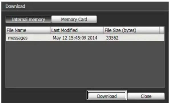
How to View Logs
The log contains the following information.
• C o d e
For the log code, see "List of Log Messages" (p. 168). The log code is shown together with one of three icons corresponding to the applicable level. If the log has no log code, no icon is shown.


Warning LevelError Level

Information Level
- Date & Time
The date and time at which the log was generated.
- Message
A message regarding the log.

Note
On the control panel of Windows, the decimal point in a value is always indicated by "." regardless of the settings of [Region and Language]. Also, the date is shown in the "yyyy/mm/dd" or "mm/dd" format, while the time is shown in the "hh:mm:ss" format. (y, m, d, h, m, and s indicate year, month, day, hour, minute, and second, respectively)
■ Saving a Log to a File/Opening a Saved Log
How to Save
Click [Save to local file] and save using the [Save As] dialog box.
How to View
Click [Open local file] and select a log file using the [Open] dialog box.
■ Copying/Searching Logs
How to Copy
Click to select the log you want to copy, and then click [Copy].
How to Search
Enter the character string for which you want to search in [Search for] and click [Search].
If the searched log is found, it is shown as selected. Click [Previous] or [Next] to search the log above or below. Lines of logs found are shown as selected.

■ Showing All Logs
Select the [Show all logs] checkbox.
When selected, even logs without a log code are shown if [Not specified] is selected for the log type [Filter].
■ Showing Filtered Logs
You can filter logs by type, code and date & time to show only the necessary information.
Set the following conditions and click [Apply filter] to show only the logs matching the specified conditions.

[Log Type]
Select the [Specify type] or [Specify code] checkbox to filter logs by type. If you do not want to filter logs by type, select [Not specified].
- Specify type
Specify the log level
Select [Error], [Warning] or [Information] for the level of logs to be shown.
Specify log output module
Select [Application], [HTTP Server] or [System] for the output source module whose logs will be displayed.
- Specify code
Specify the log code. Only logs whose code contains the entered characters are shown. If "A0" is entered, for example, logs starting with "A0" are displayed.
[Date & Time]
- [Specify start date & time] checkbox When this checkbox is selected and a date and time are entered, logs generated on or after the specified date and time are shown.
- [Specify end date & time] checkbox When this checkbox is selected and a date and time are entered, logs generated on or before the specified date and time are shown.
Important
Logs saved in the camera's internal memory are cleared when you perform [Maintenance] > [Restore Default Settings] and [Reboot], or press the reset switch on the camera.
Note
[Application], [HTTP Server], and [System] support the List of Log Messages (p. 168).
Recorded Video Utility
This utility manages video recorded on an memory card. It allows you to play back recorded video and download it to a PC, display a video list or perform filtering.
Display Screens of Recorded Video Utility

(1) [Refresh Video List]
Update the video list to the current state.
(2) [Refresh Download Status]
Update video download status to the current state.
(3) [Memory Card Details]
Displays the dialog box for details about the memory card.
(4) [Number of Videos]
Displays the number of videos in the video list.
(5) [Select All]
Select all video in the video list.
(6) [Export to mov format]
Export the [Downloaded] video selected in the video list to a mov format video file.
(7) [Enable H.264 playback] checkbox
Select to play H.264 video in the [Playback Videos] area (p. 131).
(8) Video List
Displays a list of videos recorded on an memory card and downloaded to a PC.
(9) [Delete from Camera]
Delete videos selected in the video list from the memory card.
(10)[Download]
Download videos selected in the video list to a PC.
(11)[Download to]
Specify the folder that videos are downloaded to.
(12)[Filter]
Click [Filter] to open or close the filter area. Sets criteria to narrow down the number of items displayed in the video list (p. 129).
(13)[Playback Videos] Area
Plays videos selected in the video list (p. 130).
Confirming Recorded Video

The video list displays the following information:
[Date & Time]
Displays the date and time of a video recording.
[Format]
Displays the format of a recorded video ([JPEG] or [H.264]).
[Recording Type]
Displays the type of recorded video ([Upload],
[Recording-Mode Stream], [Manual], [Timer], [Event]).
[Upload] indicates video that failed to upload from the camera, and [Recording-Mode Stream] indicates video where video transmission failed when using RM recording-mode stream.
[Video in Camera]
Displays whether or not any video remains on an memory card. When video has been deleted from an memory card after downloading it, this indicator displays [No].
[Download Status]
Displays download status of video ([Downloaded], [Not Downloaded], [Partially Downloaded]).
![CANON VB-M720F - [Download Status] - 1](/content/2026/08/1575110/images/81a366da460a9bb25c2175822beda588a2111eb4ed35e39245cb5bae4b0f192a.jpg)
Note
Clicking a header in each column sorts the video list.
■ Refreshing Video List

Click [Refresh Video List] to update the video list to the current state.
Click [Refresh Download Status] to update download status of the video list to the current state.
Selecting Videos
Click a video to select it. Use the Ctrl key or the Shift key while clicking to select multiple videos.

Click [Select All] to select all videos on the list.
Narrowing Down the Number of Videos
Use [Filter] to narrow down the number of videos that appear in the video list to the ones you need.
Set the following conditions and click [Apply filter] to show only the videos matching the specified conditions.

[Date & Time]
• [ Specify start date & time] checkbox
When this checkbox is selected and a date and time are entered, videos recorded on or after the specified date and time are shown.
• [ Specify end date & time] checkbox
When this checkbox is selected and a date and time are entered, videos recorded on or before the specified date and time are shown.
[Video Format]
Select [Specified] and select the checkboxes for the video format ([JPEG] or [H.264]) (multiple selections possible).
[Recording Type]
Select [Specified] and select the checkboxes for the type of video recording ([Upload], [Recording-Mode Stream], [Manual], [Timer], [Event]) (multiple selections possible).
[Video in Camera]
Select [Not specified], [Yes] or [No].
[Download Status]
Select [Specified] and select the checkboxes for the status of video download ([Downloaded], [Not Downloaded], [Partially Downloaded]) (multiple selections possible).
Downloading Video
Download video recorded on an memory card to a PC.
1 Specify the folder to download video to in [Download to].
Click [Browse] to specify a folder.
2 Select a video to download in the video list.
3 Click [Download].
The video is downloaded to the specified folder.

Important
Since the Recorded Video Utility processes both files downloaded to a PC and its original videos recorded on the memory card, the video list will not display correctly if files downloaded to a PC are manually deleted. In this case, click [Refresh Download Status] to refresh status of data downloaded to a PC.

Note
When the download folder is changed, the download status of the files in the download folder prior to the change becomes [Not Downloaded]. Manually copy the files in the download folder prior to the change to the new download folder to change their status to [Downloaded].
Downloaded videos are stored in a folder that is automatically created within the specified destination folder and named using the camera IP address (for example, [192.168.100.1]). Quit the Recorded Video Utility before using explorer to browse the folders before and after the change and copy the contents of the folder with the same name as the camera IP address.
After copying, start up the Recorded Video Utility, click [Refresh Download Status] and the manually copied files will appear in the video list.
For details on the folder configuration and file naming rules for the download location, see "Directory Structure for Data Downloaded with Recorded Video Utility" (p. 162).
Exporting to Video Files That Can Be Played Back
Videos downloaded from an memory card to a PC can be exported to video files that can be played back on a PC. For H.264 video, subdivided files are merged into a single file.
1 Select a video to export in the video list.
Videos whose [Download Status] is labeled [Downloaded] in the video list can be exported.
2 Click [Export to mov format].
The [Browse For Folder] dialog box appears.
3 Select a folder to export to and click [OK].
The video is exported.

Note
- The exported video files can be played back using QuickTime 7.7 and Windows Media Player 11/12. For Windows Vista and earlier, use QuickTime. However, playback when using this software is not guaranteed.
- A recorded JPEG video whose size is changed during recording and exported to a mov file cannot be played back by Windows Media Player. Use QuickTime to play it back.
Playing Back Videos
Videos selected in the video list can be played back in the [Playback Videos] area.
The appearance and operations of the [Playback Videos] area differ depending on the selected video format.

For JPEG

[Recording Date & Time]
Displays the date and time of video frames that are being displayed.
[Playback Frame No.]
Displays frame numbers and total number of video frames that are being displayed.
[Playback Interval]
• [ Real Time ]
JPEG video is played back in real time interval according to the recording time. The preceding JPEG video appears in an empty frame.
• [Equal Interval]
JPEG video is played back at a 1-second interval.
![CANON VB-M720F - [Playback Interval] - 1](/content/2026/08/1575110/images/c127bc69ac48b2e2cd3bac572b339ca3a8faf2fdcd079e6a83133991458174d2.jpg)
Note
• [Real Time] can be selected only for playback of downloaded videos.
- [Not Downloaded] or [Partially Downloaded] JPEG videos may not be played back in the order they were recorded.
Slider/Playback Control

Drag the slider to change playback position. The following buttons can also be used for playback.
| Button Description | |
| Move to first frame | |
| Move to previous frame | |
| Fast rewind | |
| Playback | |
| Pause | |
| Fast forward | |
| Move to next frame | |
| Move to last frame | |
[Save Playback Frame As]
Video frames that are being played back can be saved as a separate file.
For H.264
Select the [Enable H.264 playback] checkbox to play H.264 video in the [Playback Videos] area.
The Software Product License Agreement dialog box appears. Click [Yes] to accept the terms of the license agreement. The decoder is downloaded from the camera, enabling H.264 video playback.

[Recording Date & Time]
Displays the date and time of video frames that are being displayed.
[Playback File No.]
Displays file numbers and total number of video files that are being displayed.
![CANON VB-M720F - [Playback File No.] - 1](/content/2026/08/1575110/images/38675e1016f1702af18b7b96a470aba977882c72dc1a158690f6cbd51d672072.jpg)
Note
- The H.264 video playback interval varies depending on the download status.
If the download status is [Downloaded], each frame is played back in real time interval according to the recording time. For empty frames, the preceding frame is displayed.
If the status is [Not Downloaded] or [Partially Downloaded], empty frames are skipped upon playback. If a file is played back while still downloading, playback may momentarily pause when switching files, depending on the network environment. - [Not Downloaded] or [Partially Downloaded] videos may not be played back in the order they were recorded.
Slider/Playback Control

Drag the slider to change playback position. The following buttons can also be used for playback.
| Button Description | |
| Move to first frame | |
| Move to previous frame | |
| Playback | |
| Pause | |
| Move to next frame | |
| Move to last frame |
[Save Playback Frame As]
Video frames that are being displayed can be saved as a separate file.
Clear the [Enable H.264 playback] checkbox to play H.264 video in an external player.

[Number of downloaded video files]
The number of downloaded files the video consist of is displayed.
[Playback with External Player]
Start up the external player (Windows Media Player, etc.) and the selected video is played back.
[Open Video folder]
Open the folder storing the selected video. Double click the video file in the folder to play it back.
![CANON VB-M720F - [Open Video folder] - 1](/content/2026/08/1575110/images/a40070551445a260f3fe507cd9ef1b10d2d4e50e2749d7054c617c4e5abfb70e.jpg)
Note
- To play back H.264 videos in an external player, the videos must be downloaded to a computer (p. 130).
- The downloaded H.264 video file will have the “.mov” extension.
- When the data size for mov type files is 1 MB or greater, they are split into several files.
- If mov files are split into several files, only the initial few seconds of the first file can be played back. To play back the files in succession, use [Export to mov format] (p. 130).
- The downloaded video files can be played back using QuickTime 7.7 and Windows Media Player 11/12. For the Windows Vista operating system or earlier, use QuickTime. Use of these applications does not guarantee playback.
Deleting Videos
You can delete videos from an memory card.
1
Select a video to delete in the video list.
2
Click [Delete from Camera].
The video is deleted from the camera.

Note
If the selected videos contain [Not Downloaded] videos, a message prompting you to confirm deletion appears. Click [OK] to delete the video.
Displaying Memory Card Information
Click [Memory Card Details] to display information on the memory card inserted in the camera.

Control for Admin
This panel is used to adjust video from the camera that is displayed by each Admin Tool. The panel is available to the Privacy Mask Setting Tool, View Restriction Setting Tool, Preset Setting Tool and Intelligent Function Setting Tool.
Using Control for Admin
Click the [Control for Admin] button to display the Control for Admin Panel.

■ Opening/Closing Control Items
Clicking the title of a control item will open or close the setting items.

You can display the Control for Admin Panel and open the various control items even without obtaining the camera control privileges, but the items will be grayed out.
■ Operating the Control Items
The panel operates in the same way as Control for Admin of the Admin Viewer.

[Smart Shade Control]
You can set Smart Shade Control. For details, see "Setting the Smart Shade Control" (p. 152).
[Haze Compensation]
You can adjust the video if the subject is obscured by haze. For details, please refer to "Setting the Haze Compensation" (p. 152).
[Focus]
You can adjust focus. For details, see "Setting the Focus" (p. 153).
[Exposure]
You can adjust exposure. For details, see "Setting the Exposure" (p. 153).
Note H43 M42
The items for the Intelligent Function Setting Tool's Control for Admin will be grayed out if the [Lock camera position] checkbox is selected (p. 117) in the Intelligent Function Setting Tool.
Chapter 6
Admin Viewer/VB Viewer
☐Differences between the Admin Viewer and the VB Viewer
□User Authorities and Camera Control Privileges
□Viewer Startup and Operation
☐Camera Control and Obtaining Camera Control Privileges
□ Admin Viewer Operation and Settings
Overview of Viewer
Accessing this viewer via a web browser allows you to display images and operate the camera.
Two types of viewer are available, the Admin Viewer and the VB Viewer.
Admin Viewer

VB Viewer

Major Differences Between the Admin Viewer and the VB Viewer
• The operable ranges differ between the viewers.
Admin Viewer:
Users can use the administrative control functions, such as shooting adjustment settings or event detection display.
VB Viewer:
This viewer is limited to basic image operations for viewing images.
- Accessible controls are different.
Admin Viewer:
Users with privileged camera control can use this viewer.
Password authentication is required.
Authorized users must have privileged camera control assigned by the Administrator beforehand (p. 75).
VB Viewer:
Users with camera control authority can use this viewer. You can set the applicable options to enable/disable authentication, etc.
User Authorities and Camera Control Privileges
User authorities and their relative camera control privileges are specified as follows.
| User Authority | Camera Control Privileges | Video Distribution | Audio Distribution | |
| Privileged Camera Control | Camera Control | |||
| Administrator | ○ | ○ | ○ | ○ |
| Authorized user | ○(Can be changed) | ○(Can be changed) | ○(Can be changed) | ○(Can be changed) |
| Guest user | × | ○(Can be changed) | ○(Can be changed) | ○(Can be changed) |
* Can be changed: The Administrator can change the privileges of Authorized Users and Guest Users (p. 75).
The four authorities that can be set for users are privileged camera control, camera control, video distribution and audio distribution.
Users must have privileged camera control to use the Admin Viewer.
Users must have the video distribution authority to display images using the VB Viewer. To operate the camera using the VB Viewer, users must also have camera control authority.
Audio distribution authority is required to receive audio using the Admin Viewer and the VB Viewer.
[Administrator]
This user is given all authorities. The user name is fixed to "root".
The Administrator can launch the Admin Viewer or the VB Viewer from the [Admin Viewer] link or [VB Viewer] link, respectively, on the top page.
[Authorized User]
Authorized users can launch the Admin Viewer from the [Admin Viewer] link on the top page if they have privileged camera control. Authorized users can no longer launch the Admin Viewer upon losing privileged camera control. However, they can still launch the VB Viewer. Launching the VB Viewer can be prohibited by disabling all authorities of a given authorized user (p. 75).
[Guest User]
This user can only use the following functions:
Backlight compensation, snapshots, image display, audio distribution
H43 M42 Pan/tilt/zoom camera control
H630 H730 M620 M720 Digital PTZ
Guest users can launch the VB Viewer from the [VB Viewer] link on the top page. The Administrator can completely prohibit all camera access from guest users by disabling all their authorities.
![CANON VB-M720F - [Guest User] - 1](/content/2026/08/1575110/images/1bbf06272a1f7ad101dc60785fa6dca73b9f498f7172a838a4a47ec1a142c438.jpg)
Important
- Only the [Administrator] can transmit audio from the viewer.
- At any time, the [Administrator] can launch the Admin Viewer to override the camera control privileges of another instance of the Admin Viewer launched by an [Authorized User]. The Administrator can retain the camera control privileges, but doing so prevents authorized users from obtaining camera control privileges. After viewing the necessary information, the Administrator should always close the viewer or click [Obtain/Release Camera Control] to release the control privileges.
- The Admin Viewer launched by the [Administrator] can access only one camera at a time. While administrator authorities are used to access the camera from a given PC, access with administrator authorities from other PCs will be not be granted. In contrast, the camera can be accessed simultaneously by multiple instances of the Admin Viewer launched by [Authorized Users] from different PCs. Take note, however, that when controlling the camera, the control privileges are given to the user who accessed the camera most recently.

Note
- The factory default setting gives privileged camera control to [Authorized User] as well.
- If all guest user authorities are disabled, the user authentication dialog box will appear when the VB Viewer is launched. When an authorized user or administrator name and password are entered, the VB Viewer can be used with authorized user or administrator authorities, respectively.
Launching the Viewer
Launching the Viewer

Important
The Admin Tools Certificate must be installed on a PC that is using the Admin Viewer. (p. 26)

Note
You can also launch the Admin Viewer from the Camera Management Tool. For details, please refer to the "Camera Management Tool User Manual".
1 Start the top page of the camera (p. 31).
2 Click [Admin Viewer] or [VB Viewer] according to the user.

3 For [Admin Viewer], enter the user name and password.

Refer to "User Authentication" (p. 31) for information on the user name and password.
The viewer is launched.


Note
In environments without a proxy server, select [Internet options] > [Connections] tab > [LAN settings] and clear the [Automatically detect settings] checkbox in Internet Explorer.
Shutting Down the Viewer
Close the web browser in the viewer to shut down.
Connecting from Admin Tools
Only the administrator can connect to this viewer.
1 Launch Admin Tools.
(Refer to "Launching the Admin Tools" (p. 94) for information on launching the Admin Tools.)
2 Click [Admin Viewer].

How to Operate the Viewer
Display Screens of Admin Viewer
The following gives an overview of the functions of buttons, boxes and other screen elements displayed in the Admin Viewer.
The following screen shows the Admin Viewer with all panels opened. In practice, you only open panels that are necessary, and can put them anywhere desired in the web browser.
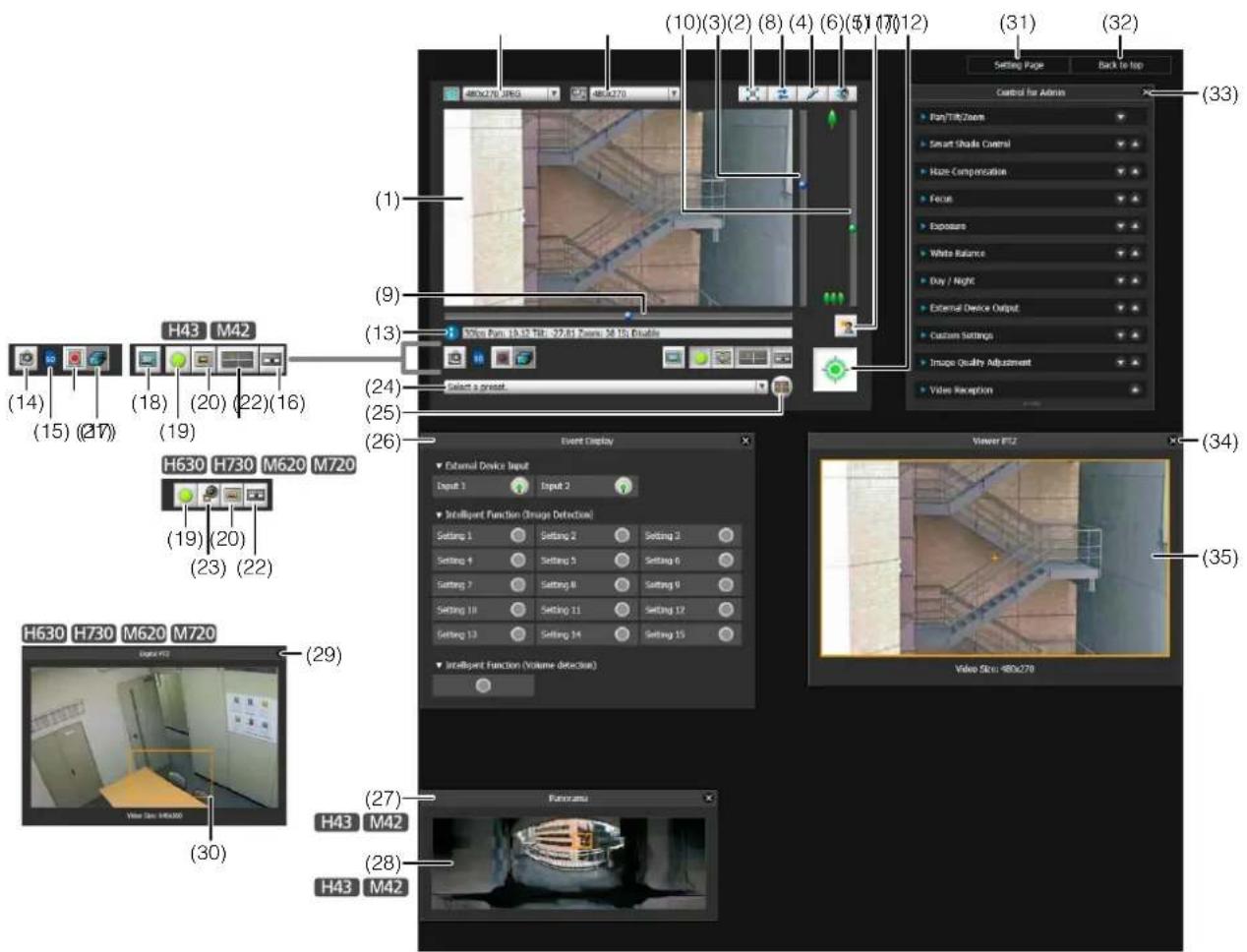
(1) Video Display Area
Displays images received from the camera.
(2) Video Size
Set the size and format of video received from the camera.
(3) Video Display Size
Set the display size of the image shown on the screen.
(4) [Full Screen Mode] button
Live images are shown in full screen mode.
(5) [Reconnect] button
The camera is reconnected.
(6) [Audio Transmission] button
Displays the Audio Transmission panel.
(7) [Audio Reception] button
Displays the Receive Audio panel.
(8) Slider for tilt
This slider is used to control the tilt (vertical movement) of the camera.
(9) Slider for pan
This slider is used to control the pan (horizontal movement) of the camera.
(10)Slider for zoom
This slider is used to control the zoom ratio.
You can zoom in (telephoto) by moving the knob upwards or zoom out (wide-angle) by moving the knob downwards.
(11)[BLC] (Back Light Compensation) button
This button turns on/off backlight compensation. This control is effective when the image is dark due to backlight.
(12)[Obtain/Release Camera Control] button
This button is used to obtain/release the camera control privileges.
(13)Information Field
Information messages, warning messages and error messages are shown to the user.
(14)[Get a Snapshot] button
A still image from the moment of clicking is displayed in a new window.
(15)Memory Card Mount Status Icon
Displays whether or not the memory card is mounted.
SD memory card is mounted.
memory card is not mounted.
(16)[Start/Stop Memory Card Recording] button
Recording to the memory card starts if you have camera control privileges. Click again to stop recording.
(17)[Recorded Video Utility] button
The Recorded Video Utility (p. 128) of the Admin Tools starts up.
(18)[Switch Area Zoom/Drag to Move] button H43 M42
Switch between Area Zoom and Drag to Move functions for dragging in the video display area.
(19)[Event Display] button
The event display panel is displayed.
(20)[Viewer PTZ] button
The viewer PTZ panel is displayed.
(21)[Panorama Display] button H43 M42
The panorama display panel is displayed.
(22)[Control for Admin] button
Displays the Control for Admin Panel.
(23)[Digital PTZ] button H630 H730 M620 M720
The Digital PTZ panel is displayed.
(24) Preset selection box
You can control the camera with presets registered in the camera beforehand.
(25)[Home Position] button
Move the camera angle to the home position.
(26)Event Display Panel
This panel is displayed upon clicking the [Event Display] button.
The panel shows the input status of external devices and the status of image and volume detection by intelligent functions.
(27)Panorama Display Panel H43 M42
This panel is displayed upon clicking the [Panorama Display] button.
(28)Panorama Display Area H43 M42
Displays panorama images registered in the camera. You can operate the camera by controlling the frame lines within the panorama display area.
(29)Digital PTZ Panel H630 H730 M620 M720
This panel is displayed upon clicking the [Digital PTZ] button.
(30)Digital PTZ Area Designator
H630 H730 M620 M720
Specify the area in the video display area to crop with Digital PTZ.
(31)[Setting Page]
The screen switches to the Settings Menu page.
(32)[Back to top]
The screen switches to the top page of the camera.
(33) Control for Admin Panel
You can operate the camera with the administrator authorities. For details, see "Using Control for Admin" (p. 151).
(34)Viewer PTZ Panel
This panel is displayed upon clicking the [Viewer PTZ] button.
(35)Viewer PTZ Area Designator
Set the cropped area in the video display area.
VB Viewer

(1) Video Display Area
Displays images received from the camera.
(2) Video Size
Set the size of video received from the camera.
(3) Video Display Size
Set the display size of the image shown on the screen.
(4) [Full Screen Mode] button
Live images are shown in full screen mode.
(5) [Reconnect] button
The camera is reconnected.
(6) [Audio Reception] button
Displays the Receive Audio panel.
(7) Control Privilege Status Indicator
Whether or not the current client has camera control privileges is shown in this area.
(8) [Obtain/Release Camera Control] button
This button is used to obtain and release the camera control privileges.
(9) Slider for tilt
This slider is used to control the tilt (vertical movement) of the camera.
(10)Slider for pan
This slider is used to control the pan (horizontal movement) of the camera.
(11)Slider for zoom
This slider is used to control the zoom ratio. You can zoom in (telephoto) by moving the knob upwards or zoom out (wide-angle) by moving the knob downwards.
(12)[BLC] (Back Light Compensation) button
This button turns on/off backlight compensation. This control is effective when the image is dark due to backlight.
(13)Information Field
Information messages, warning messages and error messages are shown to the user.
(14)[Get a Snapshot] button
A still image from the moment of clicking is displayed in a new window.
(15)[Switch Area Zoom/Drag to Move] button
H43 M42
Switch between Area Zoom and Drag to Move functions for dragging in the video display area.
(16)[Viewer PTZ] button
The Viewer PTZ panel appears.
(17)[Panorama Display] button H43 M42
The panorama display panel is displayed.
(18)[Digital PTZ] button
H630 H730 M620 M720
The Digital PTZ panel is displayed.
(19) Preset selection box
You can control the camera with presets registered in the camera beforehand.
(20)[Home Position] button
Move the camera angle to the home position.
(21)Panorama Display Panel H43 M42
This panel is displayed upon clicking the [Panorama Display] button.
(22)Panorama Display Area H43 M42
Displays panorama images registered in the camera. You can operate the camera by controlling the frame lines within the panorama display area.
(23)Digital PTZ Panel H630 H730 M620 M720
This panel is displayed upon clicking the [Digital PTZ] button.
(24)Digital PTZ Area Designator
H630 H730 M620 M720
Specify the area in the video display area to crop with Digital PTZ.
Obtaining Camera Control Privileges
The camera cannot be controlled by multiple users simultaneously. Only the user with the control privileges can control the camera. To perform backlight compensation camera control, you must obtain control privileges first.
How to Operate
Click the [Obtain/Release Camera Control] button to obtain the control privileges.
Admin Viewer
Camera Control – Privilege Display Displays camera control privilege status.
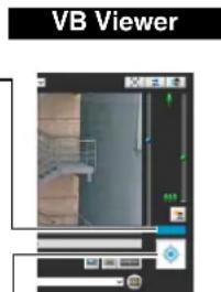
[Obtain/Release Camera Control] button
This button is used to obtain/release the camera control privileges.
■ Camera Control Privilege Status Indicator
Display of the camera control buttons and camera control status indicator changes according to the status of control privileges shown as follows.
Control privileges not assigned

With the VB Viewer, the control privilege status indicator appears in gray and an animated [Obtain/Release Camera Control] button is displayed.

The Admin Viewer does not display a control privilege status indicator. The [Obtain/Release Camera Control] button is grayed out.
Waiting for control privileges

When waiting for control privileges in the VB Viewer, the remaining standby time is shown on the control privilege status indicator.
Control privileges assigned (restricted time counting down)

After gaining control privileges with VB Viewer, the duration for which control privileges can be held exclusively over other guest users counts down.
Control privileges assigned

The control privilege status indicator is shown in blue.
The [Obtain/Release Camera Control] button in the VB Viewer is blue in the center.

The [Obtain/Release Camera Control] button in the Admin Viewer is yellow green in the center.
Controlling the Camera
Obtain camera control privileges before carrying out the following operations. These operations can be carried out in both the Admin Viewer and the VB Viewer.

Note H43 M42
- Operations carried out by clicking or dragging will not be precise.
- Users operating the camera in the Admin Viewer with the administrator authorities can control the camera outside the view restrictions.
Users operating the camera in the Admin Viewer with the authorized user authorities can control the camera only within the view restrictions. - Users operating the camera in the VB Viewer can control the camera within the view restrictions.
■ Changing the Camera Angle
H43 M42
You can change the angle by doing one of the following:
Use the pan and tilt sliders
The camera angle will change according to the knob position on the sliders. The knob can also be moved by clicking on an empty part of the slider.
Click on the video
When you click on the video display area, the camera angle changes so that the clicked position becomes the center of the video. If the desired position is not displayed in the center with one click, align the mouse pointer and click again until the desired position is displayed in the center.

Video Display Area
This slider is used to control the tilt (vertical movement) of the camera.
This slider is used to control the pan (horizontal movement) of the camera.

Note
- While using the Viewer PTZ, clicking on the video display area does not work.
- In the Admin Viewer, you can also control the pan and tilt with the camera control button (p. 152).
■ Change the Camera Angle in the Panorama Display Area H43 M42
H43 M42
1 Click the [Panorama Display] button.
2 Change the camera angle in the panorama display area.
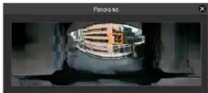
The frame lines within the display area show the image currently being captured by the camera.
Blue frame lines mean that you do not have camera control privileges.
Yellow frame lines mean that you have camera control privileges.
Move by clicking
Clicking a point in the panorama window moves the pan and tilt to center on that point.
Move by dragging
Dragging the yellow frame lines in the panorama window moves the pan and tilt to capture that area.

Note
Clicking outside the yellow frame lines and dragging will create blue frame lines. When you release the mouse button, the blue lines will turn yellow and the camera will change the pan, tilt and zoom in order to capture that area.
■ Use Area Zoom/Drag to Move
H43 M42
You can drag on the video display area to zoom in and out, and change the camera angle.

Note
You cannot not use Area Zoom or Drag to Move when using Viewer PTZ.
Use Area Zoom to Zoom In and Out
1 Click the [Switch Area Zoom/Drag to Move] button to enter mode.

2 Drag out a rectangle in the video display area.
Drag left-to-right to define an area to zoom in on. Drag right-to-left to draw out a rectangle in which will appear a preview of the video display area size in relation to the final image when zoomed out, as well as defining the center of the video display.


When operating in Area Zoom mode, an icon (zoom in: zoom out:) appears in the rectangle.
To stop Area Zoom, right-click while holding the left button and while the rectangle is displayed.
3 Release the mouse button.
When dragged left-to-right, the camera will zoom in until the area in the rectangle fills the video display area.
When dragged right-to-left, the camera will zoom out, centered around the area in the rectangle.
Use Drag to Move to Change the Camera Angle
1 Click the [Switch Area Zoom/Drag to Move] button to enter mode.

2 In the video display area, drag in the direction you would like to change the camera angle. An arrow will appear.

The camera angle will move in the direction of the arrow.
The maximum length of the arrow is half the width and height of the video display area, and movement speed increases in accordance with the length of the arrow.

Note
When using Drag to Move, the sliders will not move while the camera moves.
3 Release the mouse button.
The camera will stop.
■ Changing the Camera Zoom Ratio 43 M42
Move the knob on the slider up or down to zoom in or out The camera zoom ratio will change according to the knob position on the slider. The knob can also be moved by clicking on an empty part of the slider.


Note
- If [Digital Zoom] is set to [Enable] in [Camera] on the Setting page, the icon for the digital zoom telephoto end is displayed. (p. 58).
- In the Admin Viewer, you can also control the zoom with the Camera Control button (p. 152).
■ Change the Zoom Ratio in the Panorama Display Area H43 M4
1 Click the [Panorama Display] button.
2 Change the zoom ratio in the panorama display area displayed.

You can change the zoom ratio by dragging the yellow frame lines in the panorama window and changing the size of the frame. The zoom ratio will adjust to capture the area in the changed frame.
■ Using the Preset/Home Position
You can control the camera using presets and home position registered in the camera beforehand (p. 106). Click the preset selection box and select a preset from the displayed list to go to the selected preset camera angle. Click the [Home Position] button to move the camera angle to the home position.
![[Home Position] button Preset selection box](/content/2026/08/1575110/images/a6cb1ac5a26193aa4a51e3974b8e27463a0e48853fcf42c7f5fe087052b32271.jpg)

Note
Register presets and home position beforehand using the Preset Setting Tool (p. 108). Registered presets will appear in the preset selection box.
■ Compensating Backlight
This control is effective when the image is dark due to backlight.
Clicking [BLC] brightens images that are dark due to backlight.
Clicking the button again cancels backlight compensation.


Important
- The [BLC] button is not available if [Smart Shade Control] is set to [Auto].
- The [BLC] button is not available if [Exposure] is set to [Manual].
Magnifying Part of the Image (Viewer PTZ)
You can use the Viewer PTZ panel to magnify part of the camera's image in the video display area.
Viewer PTZ
Viewer PTZ uses the digital zoom function to enlarge part of a video without using the camera pan, tilt or zoom functions.
This function allows you to enlarge part of a video when using the camera in a locked position, for example, during use of an intelligent function.

Important
When the Viewer PTZ function is used, you cannot operate the camera by clicking/dragging the video display area.

Note
• Video cropped with Viewer PTZ will not be videos recorded manually, or by event or timer.
- The cropped position in the video display area will be reflected in full screen mode as well.
■ Opening the Viewer PTZ Panel
Click the [Viewer PTZ] button to display the viewer PTZ panel.
The [Viewer PTZ] button appearance will change as follows depending on the status of the Viewer PTZ function.

Viewer PTZ disabled (video being received by the camera appears in the video display area)

Viewer PTZ enabled (magnified video appears in the video display area)

The initial status of the Viewer PTZ panel shows the preview frame (yellow) occupying the entire image.
■ Adjusting the Preview Frame Size
Drag the preview frame line to make the frame smaller, and a magnified view of the image in the frame will be shown in the video display area.

The preview frame turns blue when you drag it.
You can also click and drag outside the preview frame to draw a new preview frame.

Note
The Viewer PTZ uses digital zoom, so the higher the digital zoom ratio, the lower the quality of the image becomes.
■ Moving the Preview Frame
You can move the preview frame to the desired position.
Move by dragging
Click within the preview frame and drag it over the subject that you want to see magnified.
The preview frame turns blue when you drag it.
Move by clicking
Click a position outside of the preview frame and the preview frame will move to that position. Click the subject that you want to see magnified.
Move using sliders H630 H730 M620 M720
You can pan, tilt and zoom the displayed video using sliders.

Note
After changing the preview frame, the video display area will continue to display the cropped video corresponding to the preview frame even after the Viewer PTZ panel is closed. However, when you reconnect to Viewer, the initial status will be restored.
■ Exiting Viewer PTZ
Click the [Viewer PTZ] button again. The Viewer PTZ panel closes and Viewer PTZ is exited.
Cropping and Displaying Part of an Image (Digital PTZ) H630 H730 M620 M720
You can use the Digital PTZ panel to crop and display part of a camera image in the video display area. It is also possible to use a preset or home position registered to the camera.
Digital PTZ
Digital PTZ is a function that facilitates simple panning, tilting, and zooming without changing the camera lens position that was adjusted at the time of installation by transmitting just part of the camera effective pixel area from the camera to the viewer.

Note
If digital PTZ is enabled while receiving H.264 video, the received video changes to JPEG format.
■ Differences Between Viewer PTZ and Digital PTZ
Viewer PTZ and Digital PTZ are both simple pan, tilt, and zoom functions that use the digital zoom function, but they
have the following differences because they employ different operating principles.
| Viewer PTZ Digital PTZ | H630 H730M620 M720 |
| Enlarges the specified part of the image transmitted from the camera and then displays it in the viewer. | Transmits only the trimmed part of the entire area that can be captured by the camera. |
| The size of the received data is large. | The size of the received data is small. |
| PTZ operation can be performed independently for each viewer. | Independent operation cannot be performed for each viewer (if multiple viewers are connected, the same display is applied in the other viewers). |
■ Opening the Digital PTZ Panel
Click the [Digital PTZ] button to display the Digital PTZ panel.

The appearance of the [Digital PTZ] button differs as follows depending on the state of the Digital PTZ function.

Digital PTZ is disabled (displays the scene as seen by the camera).

Digital PTZ is enabled (displays trimmed video).
■ Specifying a Cropping Range
Change the position and size of the preview frame on the Digital PTZ panel to specify the range to display in the video display area.
You can also click and drag outside the preview frame to draw a new preview frame.
The preview frame is blue when you have not obtained camera control privileges. When you obtain camera
control privileges, the preview frame turns yellow and you can use the following procedures to resize and move it.
■ Changing the Size
You can resize the preview frame by dragging it. The preview frame turns blue during dragging. The image inside the frame is displayed in the video display area in accordance with the size of the frame.

The preview frame size can be set to any of five sizes (the changed size is displayed under [Video Size] on the digital PTZ panel).
The sizes that can be selected depend on the [Video Size Set] setting under [Video] > [All Videos] on the Setting page (p. 61).
If the aspect ratio of the set [Video Size Set] is 16:9, the five sizes are 640 x 360, 512 x 288, 384 x 216, 256 x 144, and 128 x 72. If the aspect ratio is 4:3, the five sizes are 640 x 480, 512 x 384, 384 x 288, 256 x 192, and 128 x 96.
■ Changing the Position
You can move the preview frame by dragging the inside of the frame.
If you click any position in the Digital PTZ display area, the preview frame moves to the clicked position.

Note
The preview frame moves in stages. You cannot finely adjust the position.
■ Specifying a Range with the Sliders
You can use the pan, tilt, and zoom sliders for the video display area to specify the cropping range in the video display area. The preview frame on the Digital PTZ panel also moves in accordance with the operation of the pan, tilt, and zoom sliders.
■ Using a Preset or the Home Position
You can use a registered preset or home position to specify the range for Digital PTZ.
Click the preset selection box and select a preset from the displayed list to move the preview frame on the Digital PTZ panel to the preset position and display the image inside the frame in the video display area.
Click the [Home Position] button to move the preview frame on the Digital PTZ panel to the home position and display the image inside the frame in the video display area.

Note
Register the preset or home position beforehand using the Preset Setting Tool (p. 108). Registered presets will appear in the preset selection box.
■ Exiting Digital PTZ
Click the [Digital PTZ] button again. The Digital PTZ panel closes and Digital PTZ ends.
Although clicking the close button of the Digital PTZ panel closes the Digital PTZ panel, Digital PTZ will stay on.
However, when you reconnect to Viewer, the initial status will be restored.
Setting Video and Audio
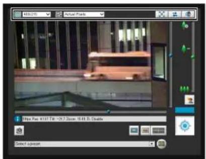
■ Changing the Video Size
You can set a desired video size for video received from the camera.
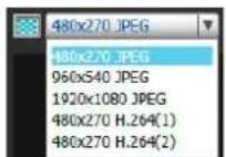
The sizes that can be selected depend on the [Video Size Set] setting under [Video] > [All Videos] on the Setting page (p. 61).
| [Video Size Set] setting | Selectable video size | |
| JPEG H.264* | 1 | |
| 1920 × 1080 / 960 × 540 / 480 × 270*4 | 480 × 270 | *2 |
| 960 × 540 | *3 | |
| 1920 × 1080 | ||
| 1280 × 720 / 640 × 360 / 320 × 180 | 320 × 180 | *2 |
| 640 × 360 | *3 | |
| 1280 × 720 | ||
| 1280 × 960 / 640 × 480 / 320 × 240 | 320 × 240 | *2 |
| 640 × 480 | *3 | |
| 1280 × 960 | ||
*1 When the [Enable H.264 reception] checkbox is checked in Admin Viewer > Control for Admin > [Video Reception] (p. 158), H.264 video sizes will be added to the menu display.
*2 The H.264 video sizes set in [Video Size] under [Video] > [H.264(1)] and [H.264(2)] (p. 62) on the Setting page are added to the menu.
*3 If [H.264(2)] is set to [Enable] under [Video] > [H.264(2)] (p. 62) on the Setting page, the video sizes for both [H.264(1)] and [H.264(2)] are added to the menu.
*4 [Video Size Set] cannot be set to [1920 x 1080 / 960 x 540 / 480 x 270] (p. 61).

Important
H.264 video cannot be displayed using VB Viewer.
■ Changing the Display Screen Size
You can change the display screen size.


The display screen sizes that can be selected depend on the [Video Size Set] setting under [Video] > [All Videos] on the Setting page (p. 61).
| [Video Size Set] setting | Selectable display size |
| 1920 x 1080 / 960 x 540 / 480 x 270* | Actual Pixels480 x 270960 x 5401920 x 1080Fit to Window |
| 1280 x 720 / 640 x 360 / 320 x 180 | Actual Pixels480 x 270640 x 3601280 x 720Fit to Window |
| 1280 x 960 / 640 x 480 / 320 x 240 | Actual Pixels480 x 360640 x 4801280 x 960Fit to Window |
* [Video Size Set] cannot be set to [1920 x 1080 / 960 x 540 / 480 x 270] (p. 61).
[Actual Pixels] displays the video at the size at which it is being captured.
[Fit to Window] displays the video at the maximum size possible in the web browser window.
■ Displaying in Full Screen Mode
You can show images over the entire display. Clicking this button will switch the viewer to full screen mode.

To close the full screen window, select [Exit Full Screen Mode] in the following menu. You can also exit full-screen mode using the button on the bottom right.
You can display the necessary panels for controlling the camera in the full screen mode. Right-click on the screen and select the necessary panel from the menu that appears.

[Start/Stop Control] Obtain and release the camera control privileges.
[Preset] Select a preset.
[Home Position] Move the camera angle to the home position.
[Panorama] H43 M42
Displays the panorama display panel.
[Start/Exit Viewer PTZ] The viewer PTZ panel is displayed.
[Start/Exit Digital PTZ] H630 H730 M620 M720 The Digital PTZ panel is displayed.
[Control] Displays the camera control panel.
[Pan/Tilt Slider] Displays the pan/tilt slider.
[Control for Admin] Displays the Control for Admin Panel (Admin Viewer only).
[Drag to Move Mode/Area Zoom Mode] H43 M42
Switch between Area Zoom and Drag to Move functions for dragging in the video display area.
[Video Capture Size] Switch video capture size.
[Snapshot] Get a snapshot.
[Audio Reception] Displays the Audio Reception panel.
[Audio Transmission] Displays the Audio Transmission panel. (Admin Viewer only).
[Event Display] Displays the event display panel (Admin Viewer only).
[Start/Stop Memory Card Recording]
Start and stop video recording to an memory card (Admin Viewer only).
[Exit Full Screen Mode] Exit full screen mode.
You can move any panel by clicking the title bar and dragging it to the desired position.
Getting a Snapshot
Captures a still image from live images and displays it in a new window.
You can also save still images.
Click [Get a Snapshot] button at the moment you want to capture a still image.

A snapshot panel will open showing a still image from the moment you clicked it. When the snapshot panel is open, click the [Get a Snapshot] button to update the image displayed in the snapshot panel.
To save a still image, right-click on it and select the save option from the menu that appears.
Enter the file name desired and save the image.


Note
• The snapshot is saved as a JPEG file.
- The saved snapshots are the same size as the video capture size.
Reconnect
Admin Viewer

VB Viewer
To reconnect the camera, click this button.

Note
If you reconnect, audio reception will stop and camera control privileges will be lost.
■ Receiving Audio
You can receive audio through the microphone attached to the camera.
Admin Viewer

VB Viewer
Click this button to receive audio.
Select the [Receive audio] checkbox in the Audio
Reception panel that appears and use the slider to set an appropriate volume.

| Icon Meaning | |
 | Receiving audio |
 | Not receiving audio |

Note
• To receive audio, set [Server] > [Audio Server] > [Audio Transmission from the Camera] to [Enable] in the setting pages beforehand (p. 69).
- The first time the Audio Reception panel is launched from the VB Viewer, a message to install the "Canon Network Camera Audio Receiver" add-on will be displayed in the information bar of the web browser. Install the add-on.
- Regardless whether or not the Audio Reception panel is open, audio will always be received if the [Receive audio] checkbox is selected in the Audio Receptionpanel.
- To use the audio function in environments that use a proxy server, the camera IP address must be specified in [Internet options] > [Connections] > [LAN settings] > [Proxy server] > [Advanced] > [Exceptions] of Internet Explorer.
Checking Information

The following icons will appear depending on the content of the information displayed.
| Icon (color) Meaning Description | ||
| (CWTS) | (Blue) Information | Appears when a camera operation has been successful. The following information appears.Help messages, such for each button and pull down menu.Frame rate informationPan4 fill zoomcamera information, image stabilization informationH630 H730 M620 M720Pan, tilt, and zoom information for Digital PTZ |
| (BXSC) | (Yellow) Warning | A message will appear notifying the user when camera control privileges cannot be obtained, audio reception stops, etc. |
| (HWGN) | (Orange) Error | Appears when a system error occurs. |

Important H43 M42
If the image stabilizer function is turned on in the setting page (p. 58), the actual viewing angle of the image will be smaller than the viewing angle displayed in the information field. Also, the viewing angle of image display becomes smaller than the angle (frame) displayed in the panorama display area.

Note
For details on the messages, see "List of Viewer Messages" (p. 178).
Performing Operations and Settings in the Admin Viewer
The operations and settings that can be performed only in the Admin Viewer are explained.
Transmitting Audio
In the Admin Viewer, you can transmit audio via an external device connected to the camera.

Click this button to transmit audio.
Use the slider to set an appropriate volume on the Audio Transmission panel that appears.
In the [Audio sending time limit], select [No Limit], [1 min(s)], [5 min(s)] or [10 min(s)].

| Icon Meaning | |
| Transmitting audio | |
| Not transmitting audio | |

Note
- To transmit audio, set [Server] > [Audio Server] > [Audio Reception from Viewer] to [Enable] on the setting page (p. 69).
- Audio transmission will continue even if you close the Audio Transmission panel.
- To use the audio function in environments that use a proxy server, the camera IP address must be specified in [Internet options] > [Connections] > [LAN settings] > [Proxy server] > [Advanced] > [Exceptions] of Internet Explorer.
Using Control for Admin
When you have obtained control privileges, click the [Control for Admin] button to display the Control for Admin Panel and perform camera operation and video settings.

■ Opening/Closing and Moving Control Items
Clicking the title of a control item will open or close it.

You can open the various control items even without obtaining the camera control privileges, but all items other than [Video Reception] are not available.
You can also reorder control items using the up/down buttons.

■ Performing Operations and Settings
H43 M42
Click the camera control buttons to set the pan, tilt and zoom operations as well as the speed.

(1) [Pan/Tilt] button
Move pan and tilt in the direction of the arrows. Operation will continue as long as you are holding down the button and will stop when you release it. Clicking the center button will make the camera face straight forwards.
(2) [Pan/Tilt Speed] button
Select a speed from [Fast], [Normal] and [Slow].
(3) [Control speed by zoom position] checkbox
Check the box to adjust the pan/tilt speed in response to the visible range. Pan/tilt speed is slowest at maximum telephoto, and fastest at maximum wide angle.
Uncheck the box to pan/tilt at a set speed.
The checkbox is always checked if [Control by zoom position] is selected in [Camera] > [Camera Control] > [Pan/Tilt Speed Control] on the setting page (p. 59). The pan/tilt speed control can be enabled/disabled using this checkbox when [Control at set speed] is selected in [Camera] > [Camera Control] > [Pan/Tilt Speed Control].
(4) [Zoom] button
Zooms in or out. Operation will continue as long as you are holding down the button and will stop when you release it.
(5) [Zoom Speed] button
Set the zoom speed to [Fast] or [Slow].
![CANON VB-M720F - [Zoom Speed] button - 1](/content/2026/08/1575110/images/6093495eb03ed21c6c29e19c41e064591215c89d50eae72cd7c0f051797701a9.jpg)
Note
Changing the [Pan/Tilt Speed] or [Zoom Speed] will not change the speed of the slider, or of the pan, tilt or zoom in panorama.
■ Setting the Smart Shade Control
The smart shade control function differs from backlight compensation in that only dark areas are brightened while bright areas are kept intact.

(1) [Smart Shade Control]
Select [Auto], [Manual], or [Disable].
(2) Adjusting the Smart Shade Control
When smart shade control is [Manual], set one of the 7 levels from [1] (Mild) to [7] (Strong).
Example: If the background is bright and the subject is hard to see, this function brightens dark areas to make the subject clearer.
In comparison to backlight compensation, smart shade control can reduce overexposure of bright areas.

OFF

Smart Shade Control

BLC (Back Light Compensation)

Important
- [Auto] cannot be selected for [Smart Shade Control] if [Exposure] is set to [Manual].
- If you set [Haze Compensation] to [Auto] or [Manual], [Smart Shade Control] is set to [Disable].

Note
- When [Auto] or [Manual] is selected for smart shade control, the video data size increases.
- When [Manual] is selected for smart shade control, setting a high compensation strength may increase screen noise. If noise is noticeable, lower the control level.
■ Setting the Haze Compensation
If the subject is obscured by haze, this adjusts contrast in the video to improve subject visibility.

(1) [Haze Compensation]
[Auto]
Automatically uses Compensation Removal.
[Manual]
Use buttons in (2) to manually set the compensation strength.
[Disable]
Disables Haze Compensation.
(2) Haze Compensation Strength
When Haze Compensation is [Manual], set one of the 7 levels from [1] (Mild) to [7] (Strong).

Important
If you set [Smart Shade Control] to [Auto] or [Manual], [Haze Compensation] is set to [Disable].

Note
- When [Auto] or [Manual] is selected for [Haze Compensation], the video data size increases.
- When using [Haze Compensation], contrast may be strong if the subject is not obscured by haze. If this happens, set [Haze Compensation] to [Manual] and set a lower Haze Compensation strength.
Setting the Focus

[Auto] H43 M42
:Automatically focuses on the subject.
[Manual]: You can adjust the focus manually by pushing the (far) and
(near) buttons.
Clicking [One-shot AF] will use autofocus to focus on a subject and then stop in manual focus.
[Fixed at Infinity] : You can set the focus so that it is fixed near infinity.
Important
- If it is set in the Admin Viewer, the same focus mode will occur in the viewers of other users also.
-
Depending on the lighting used, focus may not be maintained when switching between [Day Mode] and [Night Mode]. Focus when switching Day/Night Mode can be set in the [Day/Night Mode Focus Settings] panel in the Admin Viewer (p. 155).
-
Setting the shutter speed at [1/1 sec] in manual exposure (p. 153) will disable the [Auto] and [One-shot AF] focus modes in Control for Admin. Switch the focus to [Manual] and adjust it to your subject.
• Refer to the following for focus ranges.
H43 M42 Notes on p. 58
H630 H730 M620 M720
Notes on p.
42
H43 M42
- Changes to focus mode in the Admin Viewer will not be reflected in the settings on the setting page.
- Note that if you set the focus manually it will remain fixed.
Setting the Exposure

(1) Exposure Mode
Select from [Auto], [Manual], [Auto (Flickerless)] or [Auto (Shutter-priority AE)].
If [Auto] is selected for [Day/Night] under [Camera] in the Setting page (p. 57), select [Auto], [Auto (Flickerless)] or [Auto (Shutter-priority AE)].
[Auto]
The exposure is controlled automatically.
[Manual]
The exposure is set by adjusting the shutter speed, aperture and gain values manually.
[Auto (Flickerless)]
In this mode, video flickering caused by fluorescent lights, etc., can be reduced. The shutter speed is automatically adjusted according to the brightness of the environment in which the camera is used.
[Auto (Shutter-priority AE)]
In this mode, the desired shutter speed can be specified.
(2) [Exposure Compensation]
When [Auto], [Auto (Flickerless)] or [Auto (Shutter-priority AE)] is selected for [Exposure], the exposure compensation value desired can be selected from nine levels (-4 to +4) using the slider. To darken the image, select a negative value. To brighten the image, select a positive value.
(3) [Metering Mode]
When [Auto], [Auto (Flickerless)] or [Auto (Shutterpriority AE)] is selected for [Exposure], the metering mode can be selected from [Center-Weighted], [Average] or [Spot].
For an explanation on each item set in [Metering Mode], see [Metering Mode] in the Setting page (p. 56).
(4) [Shutter Speed]
When [Manual] or [Auto (Shutter-priority AE)] is selected for [Exposure], select the shutter speed desired. If [Manual] is selected, set the shutter speed in the range of [1/1 sec] to [1/16000 sec] from a pull-down menu. If [Auto (Shutter-priority AE)] is selected, set the shutter speed in the range of [1/2 sec] to [1/16000 sec] from a pull-down menu.
When capturing a moving subject, selecting a higher shutter speed can reduce blurry video capture.
(5) [Slow Shutter]
You can set slow shutter if [Exposure] is set to [Auto] or [Auto (Flickerless)]. Select a value in the range of [1/2 sec] to [1/30 sec] from the pull-down menu.
As slower shutter speeds generate afterimages when capturing a moving subject, select an appropriate time according to the capture conditions.
![CANON VB-M720F - [Slow Shutter] - 1](/content/2026/08/1575110/images/4dbfd4ba0c64f4df3a05763ea373243ca6a86cc2512386e7bb8e2f95ca3043e7.jpg)
(6) [Aperture]
If [Manual] is selected for [Exposure], set a desired aperture value.
Moving the slider to the left closes the aperture and darkens the image. Moving the slider to the right opens the aperture and brightens the image.
(7) [Gain]
If [Manual] is selected for [Exposure], set a desired gain value.
Moving the slider to the left decreases the gain (sensitivity to brightness) and darkens the image.
Moving the slider to the right increases the gain and brightens the image.
![CANON VB-M720F - [Gain] - 1](/content/2026/08/1575110/images/a1e0d96b5abb3c5a1d67198112531a929c7f6951511894e6398e0b98095e814d.jpg)
Important
- If the subject is a traffic signal or electronic scoreboard, etc., the captured image may flicker. In this case, try changing [Exposure] to [Auto (Shutter-priority AE)] and then select a shutter speed lower than 1/100, to see if the situation improves.
- [Exposure Compensation] and [Manual] for [Exposure] cannot be selected if [Smart Shade Control] is set to [Auto].
- When [Camera] > [Camera Control] > [AGC Limit] is set to [OFF] in the setting page and [Exposure] is set to [Auto (Shutter-priority AE)], exposure compensation and backlight compensation will not be performed.
■ Setting White Balance

(1) [Auto]
The white balance is adjusted automatically.
(2) [Light Source]
Select the light source from the pull-down menu below according to the condition in which the camera is used.
For an explanation on each item set in [Light Source], see [White Balance] in the Setting page (p. 57).
(3) [Manual]
The white balance is adjusted manually.

[One-shot WB]
This is used for forcibly locking the white balance to match the light source.
Example of setting method:
Illuminate a white subject (white paper, etc.) using the light source, making sure the subject fills the entire screen, and then execute [One-shot WB]. [R Gain], [B Gain]
When setting the white balance manually, set the values of red and blue gain in the range 0 to 1023 to match the light source.
![CANON VB-M720F - [Manual] - 2](/content/2026/08/1575110/images/1788a274f9db1133e8b0f20ca989b43309a282dfd6eeaadda4fb290fba4d5a3d.jpg)
Important
- Since the light source selection options are based on representative characteristics, proper colors may not be achieved depending on the applicable light source. In this case, use the [One-shot WB] function.
- If the subject looks greenish under mercury lamps in the [Auto] mode, select the [Mercury Lamp] mode under light source. If the image is still not shown in appropriate colors under mercury lamps when the [Mercury Lamp] mode is selected under light source, use [One-shot WB].
- When the subject has only one color, under low light conditions, or when sodium lamps, mercury lamps or certain other fluorescent lighting is used, colors may not be adjusted automatically.
- When [Day/Night] is set to [Night Mode] (including when it is set to [Auto] and night mode is judged to be applicable), the white balance function cannot be used.
- Notes on capturing video continuously day and night If a subject that seldom changes is captured in a location where the light source changes gradually, such as when capturing a subject continuously day and night, appropriate colors may not be achieved. In the above case, applying changes to the image to capture will achieve the appropriate colors.
Setting the Day/Night Mode

(1) [Auto]
The camera automatically switches to day mode or night mode depending on ambient brightness.
(2) [Day Mode]
Color image can be viewed in the normal mode.
(3) [Night Mode]
Images are shown in black and white, due to the disabling of the infrared cut filter.
(4) [Day/Night Mode Focus Settings]
Click to display the [Day/Night Mode Focus Settings] panel for making focus settings when switching Day/
Night Mode. Can only be set when [Focus] is set to [Manual] (p. 153).

H43 M42
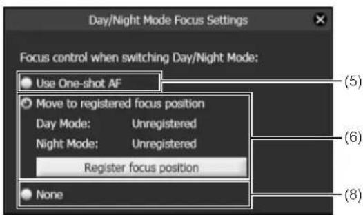
Focusing positions will vary under different light sources, such as fluorescent or infrared, since the wavelengths of these light sources vary. One of the following methods can be used to adjust the focusing position to allow for these differences when switching Day/Night Mode.
(5) [Use One-shot AF]
This is the factory default setting. Select this option to use One-shot AF when switching Day/Night Mode.
(6) [Move to registered focus position]
When switching Day/Night Mode, the focus positions preregistered for Day Mode and Night Mode in [Register focus position] will be used. For details, see "Registering the Focus Positions" (p. 156).
(7) [Compensate for light source]
H630 H730 M620 M720
Select this option to adjust the focus position to suit the lighting being used when switching to Night Mode. [Fluorescent]
Select this option to capture video under fluorescent, LED, sodium or mercury lighting. [Halogen Lamp]
Select this option to capture video under halogen or incandescent lighting.
[Infrared (740nm)]
Select this option to capture video under infrared (740 nm wavelength) lighting.
[Infrared (850nm)]
Select this option to capture video under infrared (850 nm wavelength) lighting.
[Infrared (940nm)]
Select this option to capture video under infrared (940 nm wavelength) lighting.
(8) [None] H43 M42
When switching Day/Night Mode, the camera automatically focuses on each of the fluorescent lighting focus positions set for Day Mode and Night Mode.
Registering the Focus Positions
The focus positions that are used when switching Day/Night Mode are registered as follows:
1 Select (2) [Day Mode] or (3) [Night Mode] in [Day/Night] (p. 155).
2 Under the lighting conditions selected in step 1, adjust the focus position as required while watching the video.
3 Click [Register focus position].
[Registered] will appear next to the mode, [Day Mode] or [Night Mode], picked in step 1.
4 Select the remaining mode in step 1, and repeat steps 2-3.
[Clear the registered focus position?] will appear when selecting (5) or (8), even if only one focus position has been registered for either [Day Mode] or [Night Mode]. When switching to (5) or (8), and then back to [Move to registered focus position] mode, selecting [No] will preserve the registered focus position. Selecting [Yes] will clear the registered focus position.

Important
- If the viewer is exited in [Day Mode] or [Night Mode], auto day/night stays disabled even if [Auto] is set in the setting page. To set auto day/night to enable, be sure to exit the viewer after setting [Auto].
- While making settings with the [Day/Night Mode Focus Settings] panel, it is not possible to make settings using Admin Tools on another computer.
- If [Use One-shot AF] is activated due to switching between Day/Night Mode, the camera may not be able to focus on a target subject using One-shot AF if another subject passes in front of the target at that time.
- If Night Mode will be used under infrared lighting, turn on the lighting before switching to Night Mode.
- Even if you use [Day/Night Mode Focus Settings], focus may not be maintained in Night Mode if the light source changes (ex. infrared lighting to sunlight).

Note
Refer to the following for focus ranges when Day/Night is enabled.
H43 M42 Notes on p. 58
H630 H730 M620 M720
Notes on p.
42
■ Selecting the External Device Output
You can control external device output and display the current output status using an icon. Output can be activated and deactivated by clicking this icon.

Example:
Output 1: inactive
Output 2: active
■ Registering Custom Settings
By registering settings for camera position, exposure, white balance, etc. beforehand, you can load settings using manual or automatic control. In custom settings, the setting values for the following items in the Control for Admin menu can be saved. [Smart Shade Control], [Haze Compensation], [Focus], [Exposure], [White Balance], [Image Quality Adjustment], [Day/Night]
H43 M42 [Pan/Tilt/Zoom]
Click [Register] after completing the above settings to register the custom settings.

(1) Custom setting button
Select the numbered button with the registered custom settings to load the settings.
(2) [Register Custom Settings]
The [Register Custom Settings] panel is displayed.

(3) [Register to]
Select the number for the custom setting you want to register from the selection box.
(4) [Include Current PTZ Position] checkbox
H43 M42
Select the checkbox to register the current pan, tilt, and zoom settings.
(5) [Register]
Register the current camera settings in the custom setting number selected in [Register to].
(6) [Auto Control Settings]
Displays the [Auto Control Settings] panel.
(7) [Verify registered contents of custom settings]
Displays the settings registered for the custom setting number selected in [Register to].
Setting automatic control
Click the [Auto Control Settings] button to display the [Auto Control Settings] panel, and set the [Day/Night Mode Switching] and [Timer].

(1) [Auto Control]
Select [Not used], [Day/Night Mode Switching], or [Timer] for the auto control setting.
(2) [In Day Mode], [In Night Mode]
When [Day/Night Mode Switching] is selected in [Auto Control], select the custom setting number used when switching day mode and night mode or select [None] for each item.
(3) [Timer 1] to [Timer 4]
When [Timer] is selected in [Auto Control], set the time for switching the custom setting in [Time] in 24-hour format and select the custom setting number in [Custom Setting], or select [None].
(4) [Register]
Register the auto control settings.
Important
- If both [Day/Night Mode Switching] in [Auto Control] and [Day/Night Mode Focus Control] in [Day/Night Mode Focus Settings] (p. 155) are specified, [Day/Night Mode Focus Control] has precedence.
- If the same time is specified multiple times for [Timer 1] to [Timer 4], [Register] will be disabled and the settings will not be possible.
■ Adjusting Image Quality

(1) [Noise Reduction]
Select [Mild], [Standard], or [Strong] for the noise reduction setting. Principally, this setting is more effective in low-light conditions. When set to [Strong], the noise reduction effect is increased, but the afterimage of moving subjects becomes easier to see. When set to [Mild], the noise reduction effect is decreased and resolution is increased, but the video file size becomes larger.
(2) [Sharpness]
Select a level from [1] (Mild) to [7] (Strong) for the sharpness setting. When set to [Strong] the video becomes sharper, and when set to [Mild] the video becomes softer. Also, when set to [Strong] the video file size becomes larger.
(3) [Color Saturation]
Select a level from [1] (Light) to [7] (Dark) for the color saturation setting.
■ Enabling Video Reception

(1) [Max. Frame Rate (JPEG)]
You can select the maximum frame rate for JPEG displayed video from one of twelve levels between [30 fps] to [0.2 fps]. The setting is not available when displaying H.264 video in the video display area.
(2) [Enable H.264 reception] checkbox
Select to receive H.264 video. The Software Product License Agreement dialog box appears. Click [Yes] to accept the terms of the license agreement. The decoder is downloaded from the camera, enabling H.264 video reception.
Displaying Event Status
Clicking the [Event Display] button will show the event display panel, which shows the input status of external devices, as well as the status of image and volume detection by the intelligent function.

(1) [External Device Input]
When a contact input signal is received from an external device, input will be activated and an icon will be displayed.
![CANON VB-M720F - [External Device Input] - 1](/content/2026/08/1575110/images/a7ae306777b6711e85c40df4f3ff7190b035b09410ddc49581858b26b46a0b0e.jpg)
Example:
Input 1: inactive
Input 2: active
(2) [Intelligent Function (Image Detection)]
The status of intelligent function (image detection) will be displayed. When the detection settings configured in intelligent functions (Moving Object Detection, Abandoned Object Detection, Removed Object Detection, Camera Tampering Detection or Passing Detection) enter Detected mode, the corresponding icon will turn green (p. 119).
If names are entered in [Detection Setting Name] in Intelligent Function Setting Tools (p. 119), [Setting 1] to [Setting 15] will be displayed with the corresponding name.

Example:
Setting 1: Image Detection status ON
Other settings: Image Detection status OFF
![CANON VB-M720F - [Intelligent Function (Image Detection)] - 2](/content/2026/08/1575110/images/65fccb3542a2b22f5df056bdd22a06f179e338b7d6dd8488a4352e59275074e5.jpg)
Note
The icon signifying Detection mode will be displayed for a maximum of five minutes (except for Moving Object Detection).
(3) [Intelligent Function (Volume detection)]
The volume detection status is displayed. When sound that meets the criteria selected under [Event] > [Volume Detection] in the Setting Page is detected, the icon turns green (p. 71).
![CANON VB-M720F - [Intelligent Function (Volume detection)] - 1](/content/2026/08/1575110/images/b89b4fc17a8bdceca968bfe0d95a22b1ebefe66a6bcd2c163b87c997a3ce1e3d.jpg)
Example:
Volume Detection status ON
Recording to an Memory Card Manually
Video displayed in the Admin Viewer can be manually recorded to an memory card.

Note
- To record on an memory card, an memory card must be inserted in the camera (p. 140) and [Save Logs and Videos] must be selected in the setting page > [Memory Card] > [Operation Settings].
- The format and size of the video recorded on an memory card depends on the settings made on the Setting page. Video format: [Memory Card] > [Video Format] Video size: JPEG [Video] > [JPEG] > [Video Size: Upload / Memory card] H.264 [Video] > [H.264(1)] > [Video Size]
■ Recording Videos Manually
1 If you have not yet obtained the camera control privileges, click the [Obtain/Release Camera Control] button and obtain the control privileges.
2 Click the [Start/Stop Memory Card Recording] button.

The [Start/Stop Memory Card Recording] button appearance changes as shown below depending on recording status.

Not recording
Recording
3 To stop video recording, click the [Start/Stop Memory Card Recording] button again.

Important
- Recording to the memory card will be terminated when the length of manually recorded video exceeds 300 seconds from the time recording started.
- When recording manually, do not change the settings in the [Setting Page]. Doing so may result in the termination of the manual recording.
■ Confirming Manually Recorded Video
Use the Recorded Video Utility (p. 128) to confirm video manually recorded to an memory card. Click the [Recorded Video Utility] button to start the Recorded Video Utility from the Admin Viewer.

Chapter 7
Appendix
□Memory Card Access
□Modifiers
Troubleshooting
□List of Log Messages
□List of Viewer Messages
☐ Restore Default Settings
□ List of Factory Default Settings
Index
Memory Card Access
You can set the camera so that the following data is saved automatically to the camera's memory card. ("Chapter 4 Setting Page", "[Memory Card] Memory Card Operations and Settings" (p. 84)).
When either the storage capacity of the memory card or the number of files that can be saved is reached, you cannot save further video to the memory card. If this happens, delete any unneeded video files with the Recorded Video Utility.
- Image files when recording-mode stream transmission failed to be sent due to network errors (JPEG only)
• Video files when HTTP or FTP upload failed (JPEG/H.264(1))
• Video files manually recorded by the user from the Admin Viewer (JPEG/H.264(1)) - Video files recorded by [External Device Input], [Volume Detection], and the intelligent functions when an event occurs (JPEG/H.264(1))
• Video files recorded using a timer (JPEG/H.264(1)) - Log
■ Access to the Memory Card
Use the Recorded Video Utility (p. 128) of the Admin Tools or FTP software (not included) to access the camera using the camera's IP address.
When using FTP software, set [Setting Page] > [Server] > [Use FTP Server] to [Enable].
FTP Software Settings
Address: Camera IP address (factory default setting: 192.168.100.1)
User ID: Administrator user ID (factory default setting: root)
Password: Administrator password (factory default setting: camera)

Important
- When deleting a video using a method other than the Recorded Video Utility, you must perform [Recreate Video Management Information] under [Memory Card] in the setting page (p. 85).
- Canon will assume no liability for any accident or damage resulting from use of FTP software.
■ Directory Structure for Data Downloaded with Recorded Video Utility
When video on an memory card is downloaded to a computer with the Recorded Video Utility, folders are created automatically in accordance with conditions such as the camera and the date and time.
The following shows the folder structure.
Example: H.264 video, manually recorded using a camera with an IP address of 192.168.100.1, on Sept. 10, 2015, from 16:00:00 to 16:59:59 (Camera Time Zone: GMT+09:00).

(1) Folder specified with [Download to]
(2) IP address of the camera
(3) Video recording date
(4) Recording start and end times (UTC)
(5) Time difference from UTC
(6) Recording type
E: Event
M: Manual recording
R: Recording-mode stream
T: Timer
U: Upload
(7) Video format (JPEG or H.264)

Note
- A folder is created once per hour.
- If the time difference is added to the starting and ending times, it will equal the local time.
■ File Name Format for Data Downloaded with Recorded Video Utility
Example: Video, manually recorded on Sept. 10, 2015, starting from 16:06:19 (Camera Time Zone: GMT+09:00).

(1) Video recording date
(2) File creation time (UTC)
(3) Recording start time (UTC)
(4) Recording type
E: Event
M: Manual recording
R: Recording-mode stream
T: Timer
U: Upload

Note
- The file creation time will be earlier than the actual start of recording time.
- If multiple video files were created because recording continued for several seconds or more, a new file name with different values for (2) and the sequential number ending will be used. In the above example, if recording starts at 16:09:19, and the next file is switched to 4 seconds later, the file name will be as follows.
20150910070623-070619-M00_508.mov
Since this is a continuation of the recording that started at 16:09:19, the recording start time (3) will remain as "070619". The sequential number at the end of the file name will be increased by one increment.
Modifiers
According to the setting item, you can specify parameters using modifier "% characters".
| Modifiers | Meaning Description of character | string entered |
| %n Reason for capture (number) 0 (test) | | 1 (External device input 1) | 2 (External device input 2) |33 (Timer 1) | 34 (Timer 2) | 35 (Timer 3) | 36 (Timer 4) | 145 (Volume detection) |161 (Intelligent Function Detection Setting 1) | 162 (Intelligent Function Detection Setting 2) |163 (Intelligent Function Detection Setting 3) | 164 (Intelligent Function Detection Setting 4) |165 (Intelligent Function Detection Setting 5) | 166 (Intelligent Function Detection Setting 6) |167 (Intelligent Function Detection Setting 7) | 168 (Intelligent Function Detection Setting 8) |169 (Intelligent Function Detection Setting 9) | 170 (Intelligent Function Detection Setting 10) |171 (Intelligent Function Detection Setting 11) | 172 (Intelligent Function Detection Setting 12) |173 (Intelligent Function Detection Setting 13) | 174 (Intelligent Function Detection Setting 14) |175 (Intelligent Function Detection Setting 15) | |
| %N Reason for capture(character string) | | NULL (blank entry or interval timer test) | |
| %X Width of image Number of pixels in horizontal direction | ||
| %Y Height of image Number of pixels in vertical direction | ||
| %C Camera number 1 | ||
| %D Camera name Setting for [Camera Name (alphanumeric characters)] | ||
| %P Pan position -179.99143 M42 180.00 H630 H730 M620 M7200 | ||
| %T Tilt position H43 M42 -179.99 H630 H730 M620 M720 0 | ||
| %Z Zoom position 0.01 – 300.00 | ||
| %R Rotation position 0 | ||
| %V Camera server VB-H43/VB-H630VE/VB-H630D/VB-H730F/VB-M42/VB-M620VE/VB-M620D/VB-M720F | ||
| %y Year of capture time 2001 – 2031 | ||
| %m Month of capture time 01 – 12 | ||
| %d Day of capture time 01 – 31 | ||
| %w Day of week of capture time 0 – 6 (Sunday to Saturday) | ||
| %H Hours of capture time 00 – 23 | ||
| %M Minutes of capture time 00 – 59 | ||
| %S Seconds of capture time 00 – 59 | ||
| %s Milliseconds of capture time 000 – 999 | ||
| %z Time zone of capture time -1200 – +1300 | ||
| %a Weekday name of capture time Sun | Mon | Tue | Wed | Thu | Fri | Sat | ||
| %b Month name of capture time Jan | Feb | Mar | Apr | May | Jun | Jul | Aug | Sep | Oct | Nov | Dec | ||
| %h Host Name | ||

Note
- A runtime error will occur if the specified name does not match.
- If this modifier is not defined, “%” will be deleted.
Available Modifiers
The modifiers that can be used for each setting item are specified below.
[HTTP Upload] (p. 67)
[Parameter (query string)]
All modifiers can be used.
[FTP Upload] (p. 67)
[Subdirectory Name to Create]
Only the modifiers %y,%m,%d,%w,%H,%n can be used.
[File Name to Create]
Only the modifiers %y,%m,%d,%w,%H,%M,%S,%n can be used.
[E-mail Notification] (p. 68)
[Message Body]
All modifiers can be used.
Troubleshooting
Before contacting the dealer where you purchased the product or Canon's Customer Service Center, check the items specified as follows. If a log message is displayed, check the details of the message and corresponding countermeasure in the log message list.

Note
For details on troubleshooting for Camera Management Tool, please refer to the "Camera Management Tool User Manual".
| Problem Countermeasures | |
| The camera does not start. | If you are using a PoE hub, check if the LAN cable is connected correctly.If you are using an AC adapter (sold separately), check if the AC adapter is connected correctly.Turn the camera off and on again (see “Installation Guide” > “Connecting the Camera”). |
| H630 H730 M620 M720Camera Angle Setting Tool does not operate. | Check if the LAN cable is connected correctly.Check if the camera and the PC in which the Camera Angle Setting Tool is operating are connected to the LAN in the same segment.“Application could not be started. Install .NET Framework x.x (x is the version).” If this message is displayed, install the corresponding version of .NET Framework or enable settings (p. 18).Check if you are using an older version of the Camera Angle Setting Tool. |
| The top page of the camera is not displayed. | Check if the LAN cable is connected correctly.Check if the network to which the camera is connected is set up correctly. In particular, check if the IP address, subnet mask and default gateway address are set within the ranges supported by the applicable network.If you have changed the IP address, the new address will not become effective until the camera is rebooted.Check if the correct URI (camera IP address) is entered in your web browser (p. 28, p. 31, p. 138).Check whether the connection is from a computer whose access is blocked in [Access Control] on the Setting page.Check the authentication method, [User Name], [Password], combination of certificates, and network rules for connection in [802.1X] on the Setting page with the system administrator. |
| The Admin Tools will not start.The Admin Viewer will not start. | “Your web browser is not supported.” If this message is displayed, use Internet Explorer 8 or greater.”Application could not be started. Install .NET Framework x.x (x is the version).” If this message is displayed, install the corresponding version of .NET Framework or enable settings (p. 18).“JavaScript is not available or disabled on your web browser.” If this message is displayed, set [Active Script] to [Enable] in Internet Explorer’s security settings. (See (3) below for instructions on how to set this.)“The settings from (1) to (3) below must be carried out to use the Admin Viewer and Admin Tools.” If this message is displayed, set the following.(1) Use the installer to install your Admin Tools Certificate (p. 26).(2) When using Internet Explorer 9 or greater, follow the steps in “Registering the IP address of the Camera as a Trusted Site” (p. 19) and add this web site to [Trusted sites] in Internet Explorer’s security settings.(3) In Internet Explorer click [Tools] > [Internet Options] > [Security] > [Custom level] and under the Security Settings list, set [XAML browser applications], [File download] and [Launching programs and files in an IFRAME] to [Enable]. |
| Video is not displayed. • To improve video quality, refer to “[Video] Setting Video Size, Quality and Frame Rate”(p. 61) in “Chapter 4 Setting Page” to change settings and make adjustments.Up to 30 viewers can access the camera at the same time. If this limit has been exceeded, video is not displayed and a message appears.When you are using Internet Explorer 10 or 11 in a 64-bit operating system and the camera is registered as a trusted site and protected mode is enabled, reception and playback of H.264 video may be disabled. If this occurs, disable protected mode. | |
| There is no audio. | If there is no audio, check the audio server settings of the camera and also check the sound and audio device settings for the PC.If you are using the Admin Viewer with the administrator authorities, check if the camera is connected to the RM Viewer or another viewer that lets the administrator use audio.In VB Viewer, audio cannot be used if the Canon Network Camera Audio Receiver add-on is not installed.When you are using Internet Explorer 10 or 11 in a 64-bit operating system and the camera is registered as a trusted site and protected mode is enabled, reception and transmission of audio may be disabled. If this occurs, disable protected mode. |
| The camera cannot be controlled. | If you connect the Admin Viewer as an administrator, you will have exclusive possession of the camera control privileges. If you connect to the Admin Viewer as an Authorized User, you cannot control the camera unless the administrator releases camera control. Consult the Administrator (p. 136). |
| The viewer gets disconnected. Check the network and PC for abnormality.Reboot the PC and connect again. | |
| You forgot your password. You can initialize all settings of the camera excluding date and time using the reset switch (p. 180). The administrator password required for initialization is "camera". Note, however, that network settings such as the IP address and subnet mask will be initialized and must be set again. | |
| Data cannot be uploaded. Check the upload destination in the [Upload] menu, as well as the upload operation upon event in the [Event] menu, to see if both are set correctly.You can perform an operation check based on the currently set upload destination by running a test (p. 67) from the [Upload] menu.Check [Maintenance] > [View Logs] or logs on the server to check the detailed operating environment. For [View Logs], see "Application (Uploader) Messages" (p. 169). Also see "Important" in p. 66.For the server settings, contact your System Administrator. | |
| You cannot use recording-mode stream transmission. | You cannot use recording-mode stream transmission if [Upload] > [Upload] is set to HTTP or FTP. Set [Upload] to [Upload Disabled] (p. 66). |
| Video cannot be recorded on an memory card. | To record video to an memory card when an event occurs, check the [Video Record Action] settings under [Event] in the setting page. When [Video Record Action] is set to [Upload], change it to [Record to Memory Card].When recording-mode stream video that could not be transmitted due to network errors or video for which the HTTP/FTP upload failed is not stored on the memory card, check [Operation Settings] under [Memory Card] in the setting page. When [Operation Settings] is set to [Save Log], change it to [Save Logs and Videos].To manually save recordings to an memory card, obtain camera control privileges. |
| Files cannot be saved in the setting page or Admin Tools. | Windows prohibits saving to certain folders. Accordingly, an attempt to save a file may fail. Specify [Documents], [Pictures] and other folders. |
| A message indicating "Cannot access the memory card. Please recreate the video management information on the Setting page." appears when an attempt is made to start up the Recorded Video Utility. | Select [Memory Card Information] under [Memory Card] in the setting page to check [Video Management Information Status]. When [Video Management Information Recreation Required] is displayed, click [Exec] in [Recreate Video Management Information] under [Memory Card Operations]. When video management information has been recreated, make sure that [Video Management Information Status] is [Normal]. |
List of Log Messages
Log Messages on the Camera
Log messages are classified into the following types.
| Category Level Code Fault level | |||
| crit Error 4xx | Software-level failure | (Task operations will stop) | |
| err | Error | 3xx | Operational (Operations will continue) |
| warning Warning 2xx Non-operational error | |||
| notice Warning 1xx Error external to the system | |||
| info Information 0xx Information on normal operation | |||
error

Note
If no content is recorded in a log for approximately two hours, “--MARK --” will be recorded in the message area.

Application (Camera) Messages
W001 Starting and stopping of system [info]
| Description %1 webview (W001) | |
| %1 | Starting or stopping |
| Meaning wvhttp server (webview) has started or stopped. | |
W030 Startup and shutdown of WebView Livescope Client [info]
| Description %1%2 host=, user=, prio=<Priority>(W030) | |
| %1 | W: WebView session, V: Session-less video client, N: Session-less event client |
| %2 | +: Connect, -: Disconnect |
| Meaning The cam | era server client was connected or disconnected. |
W031 Transmitted video data size [info]
| Description %1= | host=, user=, video=::(W031) |
| %1 | W: WebView session, V: Session-less video client |
| Meaning When a | client disconnected, the total data that was sent to the client displayed in number of frames. |
W040 Clearing to external memory [info]
| Description %1 the image storing - %2 (W040) | |
| %1 | Starting or stopping |
| %2 | Reason for starting/stopping |
| Meaning Started or stopped clearing stream recording to external memory. | |
W101 Invalid user name [notice]
| Description user | not found (W101) |
| Meaning The camera was accessed by an unauthorized user. | |
W102 Invalid password [notice]
| Description user | password mismatch(W102) |
| Meaning The password is invalid | |
W130 Buffer recovered [notice]
| Description stream buffer recovered (W130) |
| Meaning Image buffer for stream recording has recovered. |
W201 Invalid panorama image [warning]
| Description corrupt panorama image - ignored (W201) |
| Meaning Panorama image information acquisition failed. |
W230 Buffer overflow [warning]
| Description stream buffer overflowed (W230) |
| Meaning The image buffer for the stream recording overflowed and images were discarded. |
■ Application (Uploader) Messages
A004 Starting and stopping of uploader [info]
| Description %1 uploader (A004) |
| %1 Starting or stopping |
| Meaning The uploader was started or stopped. |
A040 Number of uploads (MAIL) [info]
| Description uploader mail: normal=%1 test=%2 (A040) |
| %1 Number of normal uploads. |
| %2 Number of test uploads. |
| Meaning Shows the number of uploads executed. |
A041 Number of uploads (FTP) [info]
| Description uploader | der ftp: normal=%1 test=%2 (A041) |
| %1 Number of normal uploads. | |
| %2 Number of test uploads. | |
| Meaning Shows the number of uploads executed. | |
A042 Number of uploads (HTTP) [info]
| Description uploader http: normal=%1 test=%2 (A042) |
| %1 Number of normal uploads. |
| %2 Number of test uploads. |
| Meaning Shows the number of uploads executed. |
A120 Resolution of upload destination name failed [notice]
| Description uploader | der cannot resolve the server name (A120) |
| Meaning The name of the upload destination could not be resolved. | |
A121 Connection to upload destination failed [notice]
| Description uploader cannot connect the server (A121) |
| Meaning Execution of connect to upload destination failed. |
A122 Connection to upload destination failed [notice]
| Description uploader cannot connect the server (A122) |
| Meaning The upload destination could not be connected due to a reason other than A120 and A121. |
A134 Invalid upload setting (FTP/HTTP mode) [notice]
| Description ftp/ht | p mode invalid. uploader setforcibly (A134) |
| Meaning The upload mode setting is invalid. The upload function was forcibly disabled. | |
A135 Invalid upload setting (FTP PORT/PASV mode) [notice]
| Description ftp port/pasv mode invalid. uploader setforcibly (A135) |
| Meaning The PORT/PASV mode setting in connection with FTP upload is invalid. The PASV mode was forcibly set. |
A136 Invalid upload setting (HTTP notification only/image mode) [notice]
| Description http r | notice/image mode invalid. uploader setforcibly (A136) |
| Meaning The notification only/image mode setting in connection with HTTP upload is invalid. The image mode was forcibly set. | |
A137 Invalid upload setting (E-mail notification) [notice]
| Description mode | invalid. uploader setforcibly (A137) |
| Meaning The e-mail | notification setting is invalid. E-mail notification was forcibly disabled. |
A138 Invalid upload setting (E-mail notification authentication mode) [notice]
| Description authentication mode invalid. uploader setforcibly (A138) |
| Meaning The setting for e-mail notification authentication mode is invalid."SMTP_AUTH" was forcibly set. |
A274 Event buffer for upload overflowed [warning]
| Description event | queue is full (A274) |
| Meaning Event buffer for upload overflowed. | |
| Countermeasure | Make adjustments to reduce the number of event occurrences. |
A275 Image buffer for upload overflowed [warning]
| Description buffer | queue is full (A275) |
| Meaning Image buffer for upload overflowed. | |
| Countermeasure | Make adjustments to reduce the number of event occurrences. Also adjust the video quality, video size and frame rate for upload. |
A470 Uploader initialization failed [crit]
| Description uploader | der initialization failure - %1 (A470) |
| %1 Error number | |
| Meaning The uploader | der could not be initialized. |
| Countermeasure | If the problem persists after rebooting the camera, the camera is faulty, arrange for servicing. |
■ Application (Audio Server) Messages
B001 Starting and shutdown of audio server [info]
| Description %1 audio. (B001) |
| %1 starting | stopping |
| Meaning The audio server was started/shut down. |
B011 Audio client connected [info]
| Description [%1] | %2 connected n=%3 (B011) |
| %1 Client type (send | recv) | |
| %2 Client host IP | address |
| %3 Total number of clients | |
| Meaning An audio client was connected. | |
B012 Audio client closed [info]
| Description [%1] | %2 closed n= %3 (B012) |
| %1 Client type (send | recv) | |
| %2 Client host IP | address |
| %3 Total number of clients | |
| Meaning An audio | client was disconnected. |
B101 Error request received [notice]
| Description %1 unusual request [%2] (B101) | |
| %1 Client host IP address | |
| %2 Error type (400 | 404) | |
| Meaning The request was denied due to a command error (400) or parameter error (404). |
B102 Client connection denied [notice]
| Description %1 request denied [%2] (B102) | |
| %1 Client host IP address | |
| %2 Denial type (41 | 43 | ...) | |
| Meaning Client connection was denied due to an authentication error (41), time specification error (42), insufficient resource (43), specification of unsupported codec (45), specification of unpermitted user level (47), too many clients (49) or invalid operation mode (4a). | |
| Countermeasure | 41: Check user name, password or user list used when connecting. 42: Check playtime or maximum connection time settings used when connecting. 43: Reconnect or restart. 45: Use supported client software. 47: Check user level used when connecting. 49: Check client number settings. 4a: Check if usage of audio server is enabled. |
B103 Client forcibly disconnected [notice]
| Description %1 access denied [%2] (B103) | |
| %1 Client host IP | address |
| %2 Denial type (41 | 42 | 4a) | |
| Meaning | Connection was initially permitted, but the setting has subsequently been changed to prohibit access, thereby triggering a forced disconnection (the denial type is the same with B102). |
B201 Event notification failure [info]
| Description cannot notify %1 event [%2] (B201) |
| %1 Event type (ald) |
| %2 Error number |
| Meaning The event notification failed. |
B202 Event reception failure [info]
| Description cannot recv event [%1] (B202) | |
| %1 Error number | |
| Meaning The event could not be received. | |
B203 Audio message send error [info]
| Description audio | message send error %1 [%2] (B203) |
| %1 Message type | |
| %2 Error number | |
| Meaning The audio | to message could not be sent. |
B204 Audio message reception failure [info]
| Description audio | message recv error [%1:%2] (B204) |
| %1 Error notification number | |
| %2 Cause of error | |
| Meaning The audio message could not be received. | |
B301 Audio device error [err]
| Description cannot use audio device for %1 [%2:%3] (B301) |
| %1 Transmission/reception type (rx | tx) |
| %2 Error handling (open | write | flush) |
| %3 Error number |
| Meaning An audio device error was detected. |
| Countermeasure If the error is not reset automatically, arrange for servicing. |
B402 Audio server initialization failed [err]
| Description wvaudio initialization error [%1] (B402) | |
| %1 Error number | |
| Meaning The audio server could not be initialized.The audio server stops. | |
| Countermeasure | If the problem persists after rebooting, the camera is faulty. Arrange for servicing. |
B403 Settings change failed [err]
| Description cannot set config [%1:%2] (B403) | |
| %1 Error notification number | |
| %2 Error number | |
| Meaning The settings could not be updated. The audio server stops. | |
| Countermeasure | If the problem persists after rebooting, the camera is faulty. Arrange for servicing. |
■ Application (Video-Related) Messages
V001 Starting and shutdown of video server [info]
| Description %1 video (V001) |
| %1 Starting or stopping |
| Meaning The video server was started/stopped. |
V020 Starting intelligent service [info]
| Description starting intelligent. (V020) |
| Meaning Intelligent service was started. |
V021 Shutting down intelligence service [info]
| Description shut down intelligent. (V021) |
| Meaning Intelligent service was shut down. |
V200 Video input warning [warning]
| Description video | %1 warning - %2 (V200) |
| %1 Video number | |
| %2 Error number | |
| Meaning An error | that permits recovery of the video input system was detected. |
| Countermeasure | Change video size or video quality, or decrease data size for each JPEG image. |
V300 Video input error [err]
| Description video | %1 warning - %2 (V300) |
| %1 Video number | |
| %2 Error number | |
| Meaning An error | in the video input was detected that may adversely affect the operation of the camera. |
| Countermeasure | If the problem persists after rebooting, the camera is faulty. Arrange for servicing. |
V320 Internal error in intelligent service [err]
| Description cannot work intelligent [%1] [%2] [%3]. (V320) | |
| %1 Error number | |
| %2 Cause of error | |
| %3 Error information | |
| Meaning An internal error occurred in intelligent service. | |
| Countermeasure | If the problem persists after rebooting, the camera is faulty. Arrange for servicing. |
V321 Pseudo mode setting error in intelligent service [err]
| Description pseudo mode setting fail. (V321) | |
| Meaning An error | occurred in the pseudo mode setting of intelligent service. |
| Countermeasure | If the problem persists after rebooting, the camera is faulty. Arrange for servicing. |
V400 Video input initialization error [crit]
| Description video | %1 initialization failure - %2 (%3) (V400) |
| %1 Video number | |
| %2 Process description | |
| %3 Error details | |
| Meaning The video | input function was stopped because the video input system could not be initialized. |
| Countermeasure | If the problem persists after rebooting, the camera is faulty. Arrange for servicing. |
V401 Video input command error [crit]
| Description video | %1 command error - %2 (%3) (V401) |
| %1 Video number | |
| %2 Process description | |
| %3 Error details | |
| Meaning The video input function was stopped because a video input command could not be processed. | |
| Countermeasure | If the problem persists after rebooting, the camera is faulty. Arrange for servicing. |
V402 Video input frozen [crit]
| Description video | %1 stalled (V402) |
| %1 Video number | |
| Meaning The video | input function was stopped because video generation stopped. |
| Countermeasure | If the problem persists after rebooting, the camera is faulty. Arrange for servicing. |
V403 Video input error [crit]
| Description video | %1 fatal error - %2 (V403) |
| %1 Video number | |
| %2 Error number | |
| Meaning The video | input function was stopped because an error that does not permit recovery of the video input system was detected. |
| Countermeasure | If the problem persists after rebooting, the camera is faulty. Arrange for servicing. |
V420 Could not start intelligent service [crit]
| Description intelligent initialization error [%1] [%2]. (V420) | |
| %1 Error number | |
| %2 Cause of error | |
| Meaning Failed to | initialize intelligent service. |
| Countermeasure | If the problem persists after rebooting, the camera is faulty. Arrange for servicing. |
V421 Intelligent service error [crit]
| Description intelligent working error [%1] [%2]. (V421) | |
| %1 Error number | |
| %2 Cause of error | |
| Meaning An error | that does not permit recovery occurred while intelligent service was running. |
| Countermeasure | If the problem persists after rebooting, the camera is faulty. Arrange for servicing. |
■ Application (Memory Card) Messages
M001 Starting and stopping of memory card control module [info]
| Description %1 sdctrl (M001) |
| %1 Starting or stopping |
| Meaning The memory card control module (sdctrl) has started or stopped. |
M201 memory card write protection [warning]
| Description Read | only filesystem (M201) |
| Meaning A write-protected memory card is inserted. | |
M203 Not enough space on memory card [warning]
| Description There is not available space (M203) |
| Meaning Insufficient memory card capacity. |
M204 Invalid file removed [warning]
| Description Invalid file %1 was removed. (M204) |
| %1 Name of removed file |
| Meaning An invalid file was removed. |
M207 Memory card removed before unmounting [warning]
| Description Memory card was pulled before unmount. (M207) |
| Meaning The memory card was removed while still mounted. |
M208 Video file limit [warning]
| Description Video | file count of %1 reached upper limit.(M208) |
| %1 Video type ([Upload], [Recording-Mode Stream], [Manual], [Timer], [Event]) | |
| Meaning The upper limit for the number of video files that can be saved for that video type has been reached.Logs will be output for [Timer] and [Event] only when [Overwrite videos] is set to [Disable]. | |
M301 memory card control module error [err]
| Description %1 process failure (M301) |
| %1 mount or unmount |
| Meaning Mount or unmount process failed. |
- HTTP Server Messages
H143 User name specification error [notice]
| Description (http_auth.c.XXX) get_password failed, IP:%1 (H143) |
| %1 IP address |
| Meaning An unknown user was specified in user authentication. |
H144 Password specification error [notice]
| Description (http | auth.c.XXX) password doesn't match for %1 username%2, IP:%3 (H144) |
| %1 URL XSS vuln | erability countermeasure implementation (process equivalent to ftpd) |
| %2 User Name | |
| %3 IP address | |
| Meaning A wrong | password was specified in user authentication. |
H201 Timeout disconnect [warning]
| Description a request for %1 timed out after writing %d seconds (H201) | |
| %1 Request URI | |
| %d 360 (Timeout time) | |
| Meaning Disconnected due to HTTP server timeout (360 sec.). | |
System Messages
S001 System started [info]
| Description starting paramd (S001) |
| Meaning Parameter management module started. |
S002 System settings changed [info]
| Description Updated system settings. (S002) | |
| Meaning Settings | not requiring rebooting were changed. |
S010 Event service started [info]
| Description starting event (S010) |
| Meaning The event service was started. |
S011 Event service shut down [info]
| Description shutdown event (S011) |
| Meaning The event service was shut down. |
S012 External device service started [info]
| Description starting extio (S012) |
| Meaning The external device input/output service was started. |
S013 External device service shut down [info]
| Description shutdown extio (S013) |
| Meaning The external device input/output service was shut down. |
S014 Timer service started [info]
| Description starting timer (S014) |
| Meaning The timer service was started. |
S015 Timer service shut down [info]
| Description shutdown timer (S015) |
| Meaning The timer service was shut down. |
S070 Change to SSL certificate [info]
| Description ssl: succeeded to %1 certificate (S070) | |
| %1 generate | load | delete | restore | |
| Meaning A certificate was generated/loaded/deleted/restored | |
| Countermeasure | None |
S220 PAN/TILT operation warning [warning]
| Description %1 warning detected. [%2] (S220) | |
| %1 PAN | TILT | |
| %2 Warning details | |
| Meaning An error occurred during operation or stopping of PAN/TILT. | |
| Countermeasure | Check that the camera is not touching the dome, etc. |
S302 Error on saving settings [err]
| Description Can't | update system settings (S302) |
| Meaning An error | generated while the system was saving a setting. Setting could not be saved. |
| Countermeasure | Provide enough memory space by deleting unnecessary files in the user memory area, etc. |
S303 Error on saving settings [err]
| Description Can't | update files of system settings (S303) |
| Meaning An error | generated while the system was saving a setting. Setting could not be saved. |
| Countermeasure | Provide enough memory space by deleting unnecessary files in the user memory area, etc. |
S307 Error on saving settings [err]
| Description (vbadmin.c XXX) Can't update system settings (S307) | |
| Meaning An error | generated while the settings were saved by the setup protocol. Setting could not be saved. |
| Countermeasure | Provide enough memory space by deleting unnecessary files in the user memory area, etc. |
S310 Working error in event service [err]
| Description cannot work event [%1] [%2] [%3] (S310) | |
| %1 Error number | |
| %2 Cause of error | |
| %3 Error information | |
| Meaning An error | occurred while the event service was running. |
| Countermeasure | If the problem persists after rebooting, the camera is faulty. Arrange for servicing. |
S311 Working error in external input/output service [err]
| Description cannot work extio [%1] [%2] [%3] (S311) | |
| %1 Error number | |
| %2 Cause of error | |
| %3 Error information | |
| Meaning An error | occurred while the external input/output device service was running. |
| Countermeasure | If the problem persists after rebooting, the camera is faulty. Arrange for servicing. |
S312 Working error in timer service [err]
| Description cannot work timer [%1] [%2] [%3] (S312) | |
| %1 Error number | |
| %2 Cause of error | |
| %3 Error information | |
| Meaning An internal error occurred in the timer service. | |
| Countermeasure | If the problem persists after rebooting, the camera is faulty. Arrange for servicing. |
S320 PAN/TILT operation error [err]
| Description %1 error occurred. [%2] (S320) | |
| %1 PAN | TILT | |
| %2 Warning details | |
| Meaning An error | occurred during operation or stopping of PAN/TILT. |
| Countermeasure | Check that the camera is not touching the dome, etc.If the error is not caused by problems such as contact with peripheral items, the camera needs to be serviced. |
S410 Event service initialization error [crit]
| Description event | initialization error [%1] [%2] (S410) |
| %1 Error number | |
| %2 Cause of error | |
| Meaning An error | occurred in the initialization of the event service. |
| Countermeasure | If the problem persists after rebooting, the camera is faulty. Arrange for servicing. |
S411 External input/output service initialization error [crit]
| Description extio | initialization error [%1] [%2] (S411) |
| %1 Error number | |
| %2 Cause of error | |
| Meaning An error | occurred in the initialization of the external input/output device service. |
| Countermeasure | If the problem persists after rebooting, the camera is faulty. Arrange for servicing. |
S412 Timer service initialization error [crit]
| Description timer | initialization error [%1] [%2] (S412) |
| %1 Error number | |
| %2 Cause of error | |
| Meaning An error | occurred in the initialization of the timer service. |
| Countermeasure | If the problem persists after rebooting, the camera is faulty. Arrange for servicing. |
S413 Timer service runtime error [crit]
| Description timer | working error [%1] (S413) |
| %1 Error number | |
| Meaning An error | occurred while the timer service was running. |
| Countermeasure | If the problem persists after rebooting, the camera is faulty. Arrange for servicing. |
■ Camera Messages
C001 Starting and stopping of camera control module [info]
| Description %1 camerad (C001) |
| %1 starting | stopping |
| Meaning The camera control module started/ stopped. |
C002 Camera application started [info]
| Description starting cameraappl (C002) |
| Meaning The camera application started. |
C201 Day/Night Mode switching warning [warning]
| Description Can't | switch Day/Night mode, because current mode is Auto. (C201) |
| Meaning Day/Night Mode could not be switched. | |
| Countermeasure | Set Day/Night Mode to manual. |
C211 Camera control command overflow [warning]
| Description command | queue overflowed (C211) |
| Meaning The camera | control command queue overflowed, and some commands were discarded. |
| Countermeasure | Allow a longer interval (200 ms) for sending the camera control command. |
■ RTP-related Messages
R001 Startup of RTP distribution module [info]
| Description starting media_plane (R001) |
| Meaning RTP distribution module started. |
R002 Stopping of RTP distribution module [info]
| Description stopping media_plane (R002) |
| Meaning RTP distribution module stopped. |
R003 RTSP PLAY request received [info]
| Description PLAY | received: client_IP=%1, profile=%2,num_of_sessions=%3 (V=%4, A=%5,M=%6, BC=%7) (R003) |
| %1 Client IP address | |
| %2 Profile name of requested PLAY | |
| %3 Total number of client sessions | |
| %4 Total distribution on count of Video stream | |
| %5 Total distribution on count of Audio stream | |
| %6 Total distribution on count of Metadata stream | |
| %7 Total distribution on count ofAudioBackChannel | |
| Meaning RTSP PLAY request was received. | |
R004 RTSP TEARDOWN request received [info]
| Description TEARDOWN received: client_IP=%1, profile=%2, num_of_sessions=%3 (V=%4, A=%5, M=%6, BC=%7) (R004) |
| %1 Client IP address |
| %2 Profile name of requested TEARDOWN |
| %3 Total number of client sessions |
| %4 Total distribution count of Video stream |
| %5 Total distribution count of Audio stream |
| %6 Total distribution count of Metadata stream |
| %7 Total distribution count of AudioBackChannel |
| Meaning RTSP TEARDOWN request was received. |
R005 Starting multicast [info]
| Description start multicast: profile=%1, num_of_sessions=%2 (V=%3, A=%4, M=%5, BC=%6) (R005) |
| %1 Client IP address |
| %2 Profile name of requested MulticastStreaming START |
| %3 Total distribution count of Video stream |
| %4 Total distribution count of Audio stream |
| %5 Total distribution count of Metadata stream |
| %6 Total distribution count of AudioBackChannel |
| Meaning Multicast was started. |
R006 Stopping multicast [info]
| Description stop multicast: profile=%1, num_of_sessions=%2 (V=%3, A=%4, M=%5, BC=%6) (R006) |
| %1 Client IP address |
| %2 Profile name of requested MulticastStreaming STOP |
| %3 Total distribution count of Video stream |
| %4 Total distribution count of Audio stream |
| %5 Total distribution count of Metadata stream |
| %6 Total distribution count of AudioBackChannel |
| Meaning Multicast was stopped. |
R101 RTP session timeout [notice]
| Description session timeout: session ID=%1 (R101) | |
| %1 Session ID | |
| Meaning RTP session has timed out. | |
R102 Information acquisition failure (RTP payload size) [notice]
| Description cannot get parameter: RTP_payload_size (R102) |
| Meaning Information acquisition has failed (RTP payload size). |
R102 Information acquisition failure (IP address) [notice]
| Description cannot get parameter: IP_address (R102) |
| Meaning Information acquisition has failed (IP address). |
R103 RTSP authentication failure [notice]
| Description RTSP | authorization error (R103) |
| Meaning RTSP authentication has failed. | |
R107 RTSP authentication failure or missing authentication information [notice]
| Description RTSP | Error: error_code=401: Unauthorized (R107) |
| Meaning RTSP authentication has failed or authentication information is missing. | |
R107 Insufficient resources [notice]
| Description RTSP | Error: error_code=503: ServiceUnavailable (R107) |
| Meaning Service | unavailable due to insufficient resources.For example, the max. number of RTP connections exceeded. |
R301 Distribution communication error [err]
| Description message queue open error: %1 (R301) | |
| %1 Modules that generate errorsRTP_CTRL_QUEUERTP_DATA_QUEUEVIDEO_CTRL_QUEUEVIDEO_DATA_QUEUEAUDIO_CTRL_QUEUEAUDIO_DATA_QUEUEEVENT_CTRL_QUEUERECVQ_METASENDQ_MEDIA | |
| Meaning A communication error occurred between modules. | |
| Countermeasure | If the problem persists after repeated attempts and rebooting, the camera may be faulty. Arrange for servicing. |
R302 Parameter acquisition failure [err]
| Description cannot get parameter: %1 (R302) | |
| %1 user_account | User accountIP_address: IP address of the cameraprofile_media_configuration:MediaConfiguration informationRTSP_port_number: RTSP port number |
| Meaning Parameter acquisition has failed. | |
R303 Metadata distribution initialization failure [err]
| Description metadata initialization error (R303) |
| Meaning Metadata distribution initialization has failed. |
R304 Abnormal termination of client [err]
| Description delete session from some kind of error: client_IP=%1 (R304) |
| %1 Client IP address |
| Meaning The client session terminated abnormally. |
R304 Client disconnected [err]
| Description connection reset by peer: client_IP=%1 (R304) |
| %1 Client IP address |
| Meaning Disconnected from client. |
R304 Client disconnected [err]
| Description RTP/HTTP connection closed by client (R304) |
| Meaning Disconnected from client. |
R305 RTSP processing error [err]
| Description RTSP | Error: error_code=500: Internal Server Error (R305) |
| Meaning An RTSP | processing error occurred. |
List of Viewer Messages
Messages Displayed in the Information Field
Messages displayed in the information field of the viewer are classified into the following three types.
| Icon Category Explanation | ||
 | Information Message | Help messages on various buttons, pull-down lists, etc., as well as frame rate and other information from the camera are shown. |
 | Warning Message A message will be displayed notifying the user when camera control privileges cannot be obtained, the audio session stops, etc. | |
 | Error Message Displayed when a system error occurs in the viewer. | |
Information Messages
| Message Explanation | |
| Connection closed by the camera. The camera was disconnected. | |
| Audio connection has been closed. The video session has continued after the audio session was disconnected (applicable to both transmission and reception). | |
| Camera control gained. Displayed when camera control is obtained. You can operate the camera. | |
| Camera control lost. Displayed when camera control is released. You cannot operate the camera until you get camera control privileges again. | |
| Use the menu displayed by right-clicking to exit the full screen mode. | When switched to full screen mode |
| Recording to memory card aborted. When recording to memory card was completed successfully | |
| The connection was terminated because the image has been flipped. | When the image was flipped during camera connection (camera connection is terminated when an image is flipped) |
| The connection was terminated because the password has been changed. | When the password of the account used to connect to the camera was changed during camera connection and then any WV-HTTP command was issued |
H43 M42
| Message Explanation | |
| {n}fps Pan : {p} Tilt : {t} Zoom : {z} IS: {Image Stabilizer value} | Communicating with the camera normally |
H630 H730 M620 M720
| Message Explanation | |
| {n}fps Pan : {p} Tilt : {t} Zoom : {z} Communicating with the camera normally (when Digital PTZ is enabled) | |
| {n}fps Communicating with the camera normally (when Digital PTZ is disabled) | |
■ Warning Messages
| Message Explanation | |
| Could not connect to the camera. Connection failed due to an invalid IP address, etc. | |
| The camera is busy. The connection limit was exceeded. | |
| Failed to get camera control privileges. | The request for camera control privileges was denied because the camera was being used by the Admin Viewer, etc. |
| Failed to establish audio connection. Connection for audio reception failed. | |
| You are not connected to the camera. An attempt was made to operate the camera when the camera was not connected. | |
| Please get camera control privileges. | An attempt was made to operate the camera without camera control privileges. |
| Another user is already connected as an administrator. | The Admin Viewer is already connected to the camera. |
| The viewer is already connected in another window. | The viewer is already available in another window. |
| No audio device. The [Audio] button has been clicked when there is no audio device or the audio device has been disabled in the PC. | |
| Failed to initialize Canon Network Camera Audio Receiver. | ActiveX plugin is not installed within ten seconds after clicking the [Audio] button. |
| Insufficient memory card capacity. An attempt was made to recording to a memory card with insufficient capacity. | |
| Recording to memory card is not allowed. | Recording to the memory card failed because [Memory Card Operation Status] > [Operation Settings] was not set to [Save Logs and Videos]. |
H43 M42
| Message Explanation | |
| You cannot control the camera unless you exit Viewer PTZ. | The video was clicked with the Viewer PTZ in the ON state while you have control privileges. |
If you have forgotten the settings and want to set the camera from the beginning, restore the factory default settings first. It is recommended that you create a backup file using [Back Up Settings] in the Camera Management Tool before restoring the factory default settings.

Note
- For details on using Camera Management Tool, please refer to "Camera Management Tool User Manual".
- For factory default settings, see p. 182.
Restoring the Initial Setting from the Maintenance Page in the Web Browser
1 Launch the web browser and display the settings menu.
To display the settings menu, you need to enter the IP address of the camera, user name and administrator password (p. 31).

2 On the Setting Menu page, click [Maintenance].
The maintenance page appears.

3 Click [Exec] under [Restore Default Settings].
A confirmation message appears, asking if you want to restore the default settings. To restore the default settings, click [OK].

Except for the following items, all user-defined settings will be discarded and restored to factory default settings after the camera is rebooted.
- Administrator password
- Network LAN, IPv4, IPv6
- Date and time
- Host access restrictions for access control
- SSL/TLS
-802.1X
Caution
- You must not turn off the camera while it is performing the [Restore Default Settings] operation. Turning off the camera at this stage may result in disabling its ability to boot correctly.
- Once [OK] is clicked, you can no longer stop the process of restoring the default settings.
Restoring Factory Default Settings with the Reset Switch on the Camera
If you have forgotten or do not know the IP address of the camera or your Administrator password, you cannot operate the camera via the network. In this case, press the reset switch at the back of the camera.
1 For VB-H630VE/VB-H630D/VB-M620VE/VB-M620D, remove the dome case.
For dome case removal, see the "Installation Guide" included with the camera.
2 Turn off the camera.
There is no on/off switch on the camera. Turn the camera on and off by plugging in or unplugging LAN cable (PoE power supply), AC adapter, or external power plug.
3 Turn on the power while pushing the reset switch, and keep pushing the reset switch for 5 seconds or more.
The reset switch is located in a recessed area. Push the switch using the tip of a slender object such as a clip.
All settings of the camera, except for the date and time, are restored to factory default settings.

Important
If the reset switch is pushed, network-related settings will also be restored to factory default settings including the camera's IP address, subnet mask, default gateway address, etc.
Accordingly, you can no longer operate the camera from the PC you were using to connect to the camera before. When initializing the camera, use the "Camera Management Tool" installed in your PC to set an IP address appropriate for the environment in which the camera is used (See "Making Initial Camera Settings" (p. 28)).

H630 M620
VB-H630VE/VB-M620VE

VB-H630D/VB-M620D

H730 M720

4 For VB-H630VE/VB-H630D/VB-M620VE/VB-M620D, attach the dome case.
For dome case attachment, see the "Installation Guide" included with the camera.
List of Factory Default Settings
| Item Setting | |
| User Name (Administrator ID) root | |
| Administrator password camera | |
| LAN | |
| LAN Interface Auto | |
| Maximum Packet Size 1500 | |
| IP v 4 | |
| IPv4 Address Setting Method Manual | |
| IPv4 Address 192.168.100.1 | |
| Subnet Mask 255.255.255.0 | |
| IPv4 Default Gateway Address | |
| AutoIP Enable | |
| IPv4 Address (AutoIP) | |
| IP v 6 | |
| IPv6 Enable | |
| Auto (RA) Enable | |
| Auto (DHCPv6) Enable | |
| IPv6 Address (Manual) | |
| Prefix Length | 64 |
| IPv6 Default Gateway Address | |
| IPv6 Address (Auto) | |
| DNS | |
| Name Server Address 1 | |
| Name Server Address 2 | |
| Auto-Setting of Name Server Address | Disable |
| Host Name | |
| Host Name Registration with DDNS | Disable |
| Search Domain | |
| Search Domain List | |
| mDNS | |
| mDNS | Enable |
| SNMP | |
| Use SNMP v1 and v2c | Disable |
| Use SNMP v3 Disable | |
| Administrator Contact Information |
| Item Setting | |
| Administration Function Name | H43 M42VB-H43/VB-M42H630 M620VB-H630VE/VB-H630D/VB-M620VE/VB-M620D/H730 M720VB-H730F/VB-M720F |
| Installation Location | |
| • SNMP v1 and v2c Server Community Name | |
| • SNMP v3 Server User Name | |
| Security Level | No authentication and no encryption |
| Authentication Algorithm | MD5 |
| Encryption Algorithm | DES |
| • Current Date and Time | |
| • Setting | |
| Setting Method | Set manually |
| Auto-Setting of NTP Server | Disable |
| NTP Server | |
| Time Zone | (GMT+09:00) Osaka, Sapporo, Tokyo |
| Daylight Saving Time | Disable |
| • Camera Name | |
| Camera Name (alphanumeric characters) | Camera |
| • Initial Camera Settings | |
| AE Mode | Auto |
| Slow Shutter | Disable |
| Shutter Speed | 1/100 |
| Exposure Compensation | 0 |
| Metering Mode | Center-Weighted |
| Focus Mode Auto M42 | |
| Smart Shade Control | Disable |
| Smart Shade Control Level | 1 (Mild) |
| White Balance | Auto |
| R Gain | 255 |
| B Gain | 255 |
| Noise Reduction | Standard |
| Sharpness | 3 |
| Item | Setting |
| Color Saturation 4Haze Compensation DisableHaze Compensation Level 4Day/Night Day ModeCamera ControlDigital Zoom Disable M42Image Stabilizer Disable M42AGC Limit 5Smart Shade Control Strength (Auto)Haze Compensation Strength (Auto)Pan/tilt speed control Control by zoom positionH43 M42Day/Night (when Auto is set)Switching Brightness StandardResponse (sec.) 20Installation ConditionsDome H43 M42LED SettingH43 H730 M42 M720Image Flip DisableCamera Position ControlRestricted to Presets No RestrictionH43 M42Camera Position without ControlExternal Input Device 1Device Name (alphanumeric characters)External Input Device 2Device Name (alphanumeric characters)External Output Device 1Device Name (alphanumeric characters)External Output Device 2Device Name (alphanumeric characters) | MediumMedium |
| DoTurn On | |
| Do not return to Home Position | |
| ■VB-H43/VB-H630VE/VB-H630D/VB-H730FAll VideosVideo Size SetJPEGVideo Quality: 480 x 270 | 1920 x 1080 / 960 x 540 / 480 x 2703 |
| Item | Setting |
| Video Quality: 960 x 540 | 3 |
| Video Quality: 1920 x 1080 | 3 |
| Video Quality: Digital PTZ (VB-H630VE/VB-H630D/ VB-H730F) | 3 |
| Video Size: video Transmission | 480 x 270 |
| Maximum Frame Rate: Video Transmission | 30.0 |
| Video Size: Upload / Memory card | 480 x 270 |
| H.264(1) | |
| Video Size 480 x 270 | |
| Bit Rate Control | Use bit rate control |
| Video Quality | 3 |
| Target Bit Rate (kbps) | 2048 |
| Frame Rate (fps) 30 | |
| I Frame Interval (sec) | 1 |
| H.264(2) | |
| H.264(2) use | Disable |
| Video Size 480 x 270 | |
| Bit Rate Control | Use bit rate control |
| Video Quality | 3 |
| Target Bit Rate (kbps) | 2048 |
| Frame Rate (fps) 30 | |
| I Frame Interval (sec) | 1 |
| ■VB-M42/VB-M620VE/VB-M620D/VB-M720F | |
| All Videos | |
| Video Size Set | 1280 x 720 / 640 x 360 / 320 x 180 |
| JPEG | |
| Video Quality: 320 x 180 | 3 |
| Video Quality: 640 x 360 | 3 |
| Video Quality: 1280 x 720 | 3 |
| Video Quality: Digital PTZ (VB-M620VE/VB-M620D/ VB-M720F) | 3 |
| Video Size: Video Transmission | 320 x 180 |
| Maximum Frame Rate: Video Transmission | 30.0 |
| Video Size: Upload / Memory card | 320 x 180 |
| H.264(1) | |
| Video Size 320 x 180 | |
| Bit Rate Control | Use bit rate control |
| Video Quality 3Target Bit Rate (kbps) 2048Frame Rate (fps) 30I Frame Interval (sec) 1H.264(2) DisableVideo Size 320 x 180Bit Rate Control Use bit rate controlVideo Quality 3Target Bit Rate (kbps) 2048Frame Rate (fps) 30I Frame Interval (sec) 1■Common to all modelsOn-screen displayDate display DisablePosition of date display Upper leftFormat of date display YYYY/MM/DDTime display DisablePosition of time display Upper leftText display Display nothingPosition of text display Upper leftText string displayColor of text Background color Color depth of text and background | WhiteBlackFill text and background color |
| RTP ServerRTPRTSP Authentication MethodRTSP PortAudio MulticastMulticast AddressMulticast PortMulticast TTLRTP Streaming 1Video Size Frame Rate Multicast Address Multicast Port Multicast TTL Audio Transmission | EnableDigest Authentication5540.0.0.001480 x 270 JPEG*50.0.0.001Disable |
| Item | Setting |
| RTP Streaming 2 | |
| Video Size | 480 x 270 JPEG* |
| Frame Rate | 10 |
| Multicast Address | 0.0.0.0 |
| Multicast Port | 0 |
| Multicast TTL | 1 |
| Audio Transmission | Disable |
| RTP Streaming 3 | |
| Video Size | 480 x 270 JPEG* |
| Frame Rate | 15 |
| Multicast Address | 0.0.0.0 |
| Multicast Port | 0 |
| Multicast TTL | 1 |
| Audio Transmission | Disable |
| RTP Streaming 4 | |
| Video Size | 480 x 270 JPEG* |
| Frame Rate | 30 |
| Multicast Address | 0.0.0.0 |
| Multicast Port | 0 |
| Multicast TTL | 1 |
| Audio Transmission | Disable |
| RTP Streaming 5 | |
| Video Size | H.264(1) |
| Frame Rate | 5 |
| Multicast Address | 0.0.0.0 |
| Multicast Port | 0 |
| Multicast TTL | 1 |
| Audio Transmission | Disable |
| General Upload | |
| Upload | Upload Disabled |
| Video Format | JPEG |
| Frame Rate | 1 |
| Pre-event Buffer (number of frames) | 0 |
| Post-event Buffer (number of frames) | 0 |
| Pre-event Buffer (sec) 0 | |
| Post-event Buffer (sec) | 0 |
| HTTP Upload |
* [320 x 180 JPEG] for the VB-M42/VB-M620VE/VB-M620D/VB-M720F.
| Item | Setting |
| Notification Notification Only with URIUser NameProxy ServerProxy Port 80Proxy User NameParameter (query string)FTP UploadNotification Video data upload with FTPFTP ServerUser NamePASV Mode EnableFile Upload PathFile Naming YYMMDDHHMMSSmsSubdirectory Name to Create File Name to Create image.jpgFile Name to Create video.movMaximum Number of Loops 0E-mail NotificationNotification Text OnlyMail Server NameMail Server Port 25Sender (From)Recipient (To)Authentication NoneUser NamePOP ServerSubjectMessage Body | HTTP |
| Video ServerMaximum Number of Clients 30Camera Control Queue Length 30Maximum Connection Time (sec.)Camera Control Time (sec.) 20Audio S er verAudio Transmission from the CameraInput Volume 50Voice Activity Detection Disable | 0Disable |
| Item | Setting |
| Audio Reception from Viewer | Disable |
| Output Volume | 50 |
| Echo Canceller | Disable |
| Audio Input | Line In |
| • HTTP Server | |
| Authentication Method Digest Authentication | |
| HTTP Port | 80 |
| HTTPS Port | 443 |
| • FTP Server | |
| FTP Server | Disable |
| • WS-Security | |
| Check Time on Authentication | Check |
| • Video Record Setting | |
| Video Record Action | Upload |
| • Volume Detection | |
| Volume Detection Event | Disable |
| Detect Criteria | The reference volume level or above |
| Reference Volume Level | 50 |
| Detect Criteria Duration (sec) | 0 |
| ON Event Operation | Disabled |
| OFF Event Operation | Disable |
| Ongoing ON Event Operation | Disable |
| Preset H43 M42 | None |
| Video Record | Disable |
| E-mail Notification | Disable |
| External Device Output for ON Event | Disable |
| External Device Output for OFF Event | Disable |
| • External Device Output 1 | |
| Operation Mode | Normally Open |
| Active Output Format | Continuous |
| Pulse Output Time (sec) | 1 |
| • External Device Output 2 | |
| Operation Mode | Normally Open |
| Active Output Format | Continuous |
| Pulse Output Time (sec) | 1 |
| • External Device Input | |
| External Device Input Event | Enable |
| • External Device Input 1 | |
| Operation Mode | Normally Open |
| Active Event Operation Disable | |
| Inactive Event Operation Disable | |
| Ongoing Active Event Operation Disable | |
| Preset H43 M42 | None |
| Video Record Disable | |
| E-mail Notification Disable | |
| External Device Output for Active Event | Disable |
| External Device Output for Inactive Event | Disable |
| Audio Playback at Active Event Disable | |
| Audio Playback at Inactive Event | Disable |
| Sound Clip | |
| Volume 50 | |
| Day/Night Mode Switching Disable | |
| • External Device Input 2 | |
| Operation Mode Normally Open | |
| Active Event Operation Disable | |
| Inactive Event Operation Disable | |
| Ongoing Active Event Operation Disable | |
| Preset H43 M42 | None |
| Video Record Disable | |
| E-mail Notification Disable | |
| External Device Output for Active Event | Disable |
| External Device Output for Inactive Event | Disable |
| Audio Playback at Active Event Disable | |
| Audio Playback at Inactive Event | Disable |
| Item | Setting |
| • Time 2Timer Event DisableStart Time 00:00End Time 00:00Repeat IntervalVideo Record DisableE-mail NotificationExternal Device Output• Time 3Timer Event DisableStart Time 00:00End Time 00:00Repeat IntervalVideo Record DisableE-mail NotificationExternal Device Output• Time 4Timer Event DisableStart Time 00:00End Time 00:00Repeat IntervalVideo Record DisableE-mail NotificationExternal Device Output• Sound Clip Upload 1Sound Clip Name• Sound Clip Upload 2Sound Clip Name• Sound Clip Upload 3Sound Clip Name | NoneDisableDisableNoneDisableNoneDisableDisable |
| • Administrator Password• Authorized User AccountUser List• User AuthorityAuthorized UserPrivileged Camera ControlCamera ControlVideo DistributionAudio DistributionGuest userCamera Control | cameraCheckedCheckedCheckedCheckedCheckedChecked |
| Item Setting | |
| Video Distribution Checked | |
| Audio Distribution Checked | |
| • IPv4 Host Access Restrictions | |
| Apply Host Access Restrictions Disable | |
| Default Policy Authorize Access | |
| Network Address / Subnet 01: / 32 Yes | |
| 02: / 32 Yes | |
| 03: / 32 Yes | |
| 04: / 32 Yes | |
| 05: / 32 Yes | |
| 06: / 32 Yes | |
| 07: / 32 Yes | |
| 08: / 32 Yes | |
| 09: / 32 Yes | |
| 10: / 32 Yes | |
| 11: / 32 Yes | |
| 12: / 32 Yes | |
| 13: / 32 Yes | |
| 14: / 32 Yes | |
| 15: / 32 Yes | |
| 16: / 32 Yes | |
| 17: / 32 Yes | |
| 18: / 32 Yes | |
| 19: / 32 Yes | |
| 20: / 32 Yes | |
| • IPv6 Host Access Restrictions | |
| Apply Host Access Restrictions Disable | |
| Default Policy Authorize Access | |
| Prefix / Prefix Length 01: / 128 Yes | |
| 02: / 128 Yes | |
| 03: / 128 Yes | |
| 04: / 128 Yes | |
| 05: / 128 Yes | |
| 06: / 128 Yes | |
| 07: / 128 Yes | |
| 08: / 128 Yes | |
| 09: / 128 Yes | |
| 10: / 128 Yes | |
| 11: / 128 Yes | |
| 12: / 128 Yes | |
| 13: / 128 Yes |
| Item Setting | |
| 14: / 128 Yes | |
| 15: / 128 Yes | |
| 16: / 128 Yes | |
| 17: / 128 Yes | |
| 18: / 128 Yes | |
| 19: / 128 Yes | |
| 20: / 128 Yes | |
| IPsec Auto Key Exchange | |
| Auto Key Exchange Settings | |
| IPsec SA Encryption Algorithm AES->3DES | |
| IPsec SA Authentication Algorithm | HMAC_SHA1_96 |
| IPsec SA Validity Period (min) | 480 |
| ISAKMP SA Encryption Algorithm | AES->3DES |
| ISAKMP SA Authentication Algorithm | SHA1 |
| DH Group | Group 14->Group 5 ->Group 2 |
| ISAKMP SA Validity Period (min) | 480 |
| IPsec Set 1 | |
| IPsec Set | Disable |
| IPsec Mode | Tunnel Mode |
| Destination IPv4 Address | |
| Destination IPv6 Address | |
| Source IPv4 Address | |
| Source IPv6 Address | |
| Security Protocol | ESP |
| Security Gateway IPv4 Address | |
| Security Gateway IPv6 Address | |
| Destination Subnet Mask Length | 16 |
| Destination Prefix Length | 16 |
| IKE Pre-Shared Key | |
| SA ESP Encryption Algorithm | AES |
| SA ESP Authentication Algorithm | HMAC_SHA1_96 |
| SA ESP Encryption Key(outbound) | |
| SA ESP Authentication Key(outbound) | |
| SA ESP SPI (outbound) | |
| SA ESP Encryption Key(inbound) | |
| SA ESP Authentication Key (inbound) | |
| SA ESP SPI (inbound) | |
| SA AH Authentication Algorithm HMAC_SHA1_96 | |
| SA AH Authentication Key (outbound) | |
| SA AH SPI (outbound) | |
| SA AH Authentication Key (inbound) | |
| SA AH SPI (inbound) | |
| • IPsec Set 2 | |
| IPsec Set Disable | |
| IPsec Mode Tunnel Mode | |
| Destination IPv4 Address | |
| Destination IPv6 Address | |
| Source IPv4 Address | |
| Source IPv6 Address | |
| Security Protocol ESP | |
| Security Gateway IPv4 Address | |
| Security Gateway IPv6 Address | |
| Destination Subnet Mask Length 16 | |
| Destination Prefix Length 16 | |
| IKE Pre-Shared Key | |
| SA ESP Encryption Algorithm AES | |
| SA ESP Authentication Algorithm HMAC_SHA1_96 | |
| SA ESP Encryption Key (outbound) | |
| SA ESP Authentication Key (outbound) | |
| SA ESP SPI (outbound) | |
| SA ESP Encryption Key (inbound) | |
| SA ESP Authentication Key (inbound) | |
| SA ESP SPI (inbound) | |
| SA AH Authentication Algorithm HMAC_SHA1_96 | |
| SA AH Authentication Key (outbound) | |
| SA AH SPI (outbound) | |
| SA AH Authentication Key (inbound) | |
| SA AH SPI (inbound) | |
| • IPsec Set 3 | |
| IPsec Set Disable |
| Item Setting | |
| IPsec Mode Tunnel ModeDestination IPv4 AddressDestination IPv6 AddressSource IPv4 AddressSource IPv6 AddressSecurity Protocol ESPSecurity Gateway IPv4 AddressSecurity Gateway IPv6 AddressDestination Subnet Mask Length 16Destination Prefix Length 16IKE Pre-Shared KeySA ESP Encryption Algorithm AESSA ESP Authentication AlgorithmSA ESP Encryption Key(outbound)SA ESP Authentication Key(outbound)SA ESP SPI (outbound)SA ESP Encryption Key(inbound)SA ESP Authentication Key(inbound)SA ESP SPI (inbound)SA AH Authentication Algorithm HMAC_SHA1_96SA AH Authentication Key(outbound)SA AH SPI (outbound)SA AH Authentication Key(inbound)SA AH SPI (inbound) | HMAC_SHA1_96 |
| • IPsec Set 4IPsec Set DisableIPsec Mode Tunnel ModeDestination IPv4 AddressDestination IPv6 AddressSource IPv4 AddressSource IPv6 AddressSecurity Protocol ESPSecurity Gateway IPv4 AddressSecurity Gateway IPv6 AddressDestination Subnet Mask Length 16Destination Prefix Length 16 | |
| IKE Pre-Shared KeySA ESP Encryption Algorithm AES | HMAC_SHA1_96 |
| SA ESP Authentication Algorithm | |
| SA ESP Encryption Key(outbound) | |
| SA ESP Authentication Key(outbound) | |
| SA ESP SPI (outbound) | |
| SA ESP Encryption Key(inbound) | |
| SA ESP Authentication Key(inbound) | |
| SA ESP SPI (inbound) | |
| SA AH Authentication Algorithm H | MAC_SHA1_96 |
| SA AH Authentication Key(outbound) | |
| SA AH SPI (outbound) | |
| SA AH Authentication Key(inbound) | |
| SA AH SPI (inbound) | |
| • IPsec Set 5IPsec Set DisableIPsec Mode Tunnel ModeDestination IPv4 AddressDestination IPv6 AddressSource IPv4 AddressSource IPv6 AddressSecurity Protocol ESPSecurity Gateway IPv4 AddressSecurity Gateway IPv6 AddressDestination Subnet Mask Length 16Destination Prefix Length 16IKE Pre-Shared KeySA ESP Encryption Algorithm AES | HMAC_SHA1_96 |
| SA ESP Authentication Algorithm | |
| SA ESP Encryption Key(outbound) | |
| SA ESP Authentication Key(outbound) | |
| SA ESP SPI (outbound) | |
| SA ESP Encryption Key(inbound) |
| Item Setting | |
| SA ESP Authentication Key (inbound) | |
| SA ESP SPI (inbound) | |
| SA AH Authentication Algorithm H | MAC_SHA1_96 |
| SA AH Authentication Key (outbound) | |
| SA AH SPI (outbound) | |
| SA AH Authentication Key (inbound) | |
| SA AH SPI (inbound) | |
| • Certificates | |
| Certificate Status Not Installed | |
| Country (C) | |
| State/Province (ST) | |
| Locality (L) | |
| Organization (O) | |
| Organizational Unit (OU) | |
| Common Name (CN) | |
| Validity Period Start Date | |
| Validity Period End Date | |
| • Encrypted Communications | |
| HTTPS Connection Policy HTTP | |
| • 802.1X Authentication | |
| 802.1X Authentication Disable | |
| Authentication Status Stop | |
| • Authentication Method | |
| Authentication Method | EAP-MD5 |
| User Name | |
| • Memory Card Operations | |
| Operation Settings | Save Logs and Videos |
| Video Format | JPEG |
| Pre-event Buffer (number of frames) | 0 |
| Post-event Buffer (number of frames) | 0 |
| Pre-event Buffer (sec) 0 | |
| Post-event Buffer (sec) | 0 |
| Overwrite videos | Disable |
| Delete Videos | |
| Recreate Video Management Information | |
| • Log Notifications | |
| Use log notifications | Disable |
| Notification Level Error | |
| Mail Server Name | |
| Mail Server Port 25 | |
| Sender (From) | |
| Recipient (To) | |
| Authentication None | |
| User Name | |
| POP Server |
Index
Numerics
802.1X Authentication 82
A
Abandoned Object Detection 122
Access Control 75
Admin Tools 92
Admin Tools Certificate 15,26
Admin Viewer 139, 151
Administrator 137
Administrator Password 50
AE Mode 56
AGC Limit 58
Aperture 154
Area Zoom 143
Audio Distribution 75, 136
Audio Multicast 64
Audio Reception 69, 139, 149
Audio Server 69
Audio Transmission 69, 139, 151
Authentication Method 70,82
Authorized User 75,137
Auto Control Settings 157
Auto Key Exchange 77
AutoIP 51
B
Back Up Settings 88
Basic Authentication 70
Basic Camera Settings 28
Bit Rate Control 62
BLC (Back Light Compensation) 140, 144
C
Camera Angle Setting Tool 26,35
Camera Control 75,136
Camera Control Privilege Status Indicator ..... 141
Camera Control Privileges 136, 141
Camera Management Tool 15, 26, 28
Camera Name 56
Camera Position Control 59
Camera Specification File 43
Camera Tampering Detection 114, 122
Certificate Information 82
Certificate Management 80, 82
Client 69,82
Color Saturation 57, 158
Control for Admin 133, 151
Custom Installation 26
Custom Settings 156
D
Date 54
Date and Time 54
Day Mode 59,155
Day/Night 57, 59, 155
Day/Night Mode Focus Settings 155
Daylight Saving Time 55
Default Gateway Address 51
Delete Videos 85
Detection Area 120
Detection Criteria 71, 119, 121
Detection Line 121
Detection Setting 124
Detection Type 113, 118, 121
Device Information 88
Device Name 60
DHCP 50
Digest Authentication 70
Digital PTZ 146
Digital Zoom 58,144
Display Options 116
Display Screen Size 148
DNS 51
Dome 59
Drag to Move 143
E
Easy Installation 26
Echo Canceller 70
E-mail Notification 68
Encrypted Communications 81
Error Message 178
Event 71, 120
Event Display 124, 158
Event Logs 88
Exposure 153
Exposure Compensation ....42, 56
External Device Input 72,158
External Device Name 60
External Device Output 156
F
Factory Default Settings ....180, 182
Filter 127, 129
Focus 42,153
Focus Mode ....57
Format 84,129
Frame Rate 62
FTP 162
FTP Server 70
FTP Upload 67
Full Screen Mode 148
G
Gain 57,154
Guest User 137
H
H.264(1) 62
H.264(2) 62
Haze Compensation 57,152
Haze Compensation Strength ....58
Home Position 59, 108, 144
Host Access Restrictions 75, 76
HTTP Port 70
HTTP Server 70
HTTP Upload 67
HTTPS Connection Policy 81
HTTPS Port 70
|
I Frame Interval 62
Image Flip 41,59
Image Quality Adjustment ....157
Image Stabilizer ....58
Information Field 140, 150
Information Message 178
Infrared Cut Filter 155
Initial Camera Settings ....56
Initial Settings ....180
Input Volume 69
Installation Conditions 59
Installation Guide 5
Installing the Necessary Software 26
Intelligent Function Setting Tool 113
IP Address 50
IPsec 77
IPv4 50
IPv4 Host Access Restrictions 75
IPv6 51
IPv6 Host Access Restrictions 76
J
JPEG 61
L
LAN 50
Language Button 31
LED 59
Lock camera position 117
Log Code 126
Log Messages 168
Log Notifications 88
Log Viewer 125
Logs 88,125
M
Maintenance 88
Max. Frame Rate 158
Maximum Frame Rate 61
Maximum Packet Size 50
mDNS 52
Memory Card 14, 84, 140, 162
Memory Card Information 85
Memory Card Operations 84, 85
Memory Card Recording 149, 159
Message
Error Message 178
Information Message 178
Log Messages 168
Warning Message 178
Metering Mode 56, 154
Microphone 69
Modifiers 164
Mount 85
Moving Object Detection 121
Multicast 64
N
Name Server Address 51
Network 50
Network Address/Subnet 75
Night Mode 59,155
Noise Reduction 57, 157
NTP Server 54
0
One-shot AF 153
One-shot WB 154
On-screen Display 62
Operating the External Device Output 156
Operation Mode 72, 73
Output Volume 69
Overwrite videos 84
P
Pan 41, 105, 142
Pan/Tilt Speed Control 59
Panorama Creation Tool 99
Panorama Display 140, 141
Panorama Display Area 142, 144
Panorama Screen 103, 107
Parameters 67, 164
Passing Detection 115, 123
Password 28,31
Playback Videos 130
PoE Supply 181
Post-event Buffer 66,84
Pre-event Buffer 66,84
Prefix 76
Preset 72,73
Use 144
Preset Setting Tool 106
Preset Tour 111
Privacy Mask Setting Tool 95
Privileged Camera Control 75, 136
Privileges 141
Pulse 72
R
Reboot Item 87
Reconnect 149
Recorded Video Utility 128
Recording Manually 159
Reference Volume Level 71
Removed Object Detection 122
Reset Switch 180
Self-Signed Certificate 80
Server 69
Setting Menu 46
Setup CD-ROM 5
Sharpness 57,157
Shutter Speed 56,154
Slow Shutter 56,154
Smart Shade Control 57,152
Smart Shade Control Strength 58
Snapshot 149
SNMP 52
Sound Clip Upload 74
SSL/TLS Certificate 80
Subnet Mask 50
Switch Area Zoom/Drag to Move 140
T
Target Bit Rate 62
Tilt 41, 105, 142
Time 54
Time Zone 54
Timer 73,157
Troubleshooting 166
Trusted Site 19,30
TTL 64
U
Unmount 84
Upload 66
User Account 75
User Authentication 31
User Authority 75,136
User List 75
User Name 31
User Page 46
V
VB Viewer 135, 140
Video Distribution 75, 136
Video Format 66, 84, 129
Video Management Information 85
Video Quality 61, 62
Video Reception 158
Video Record 72, 73, 74, 120
Video Record Action 71
Video Record Setting 71
Video Saving 85
Video Server 69
Video Size 61, 139, 147
View Restriction Setting Tool ....102
Viewer
Admin Viewer 139, 151
RM-Lite Viewer 17
VB Viewer 140
Viewer PTZ 145
Voice Activity Detection 69
Volume 73,120
Volume Detection 71, 158
W
Warning Message 178
White Balance 57,154
WS-Security 70
Z
Zoom 42,139,144


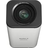
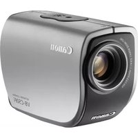
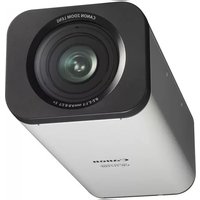
- INTRODUCTION
- DISCLAIMER
- NOTES
- NOTES ON NETWORK SECURITY
- COPYRIGHT
- NOTES ON PRIVACY AND PUBLICITY RIGHTS REGARDING THE USE OF VIDEO/AUDIO
- LEGAL NOTICE
- TRADEMARK NOTICE
- WARNING
- NOTES ON THE INCLUDED SOFTWARE RM-LITE (DISCLAIMER)
- NOTES ON LICENSE AGREEMENT FOR INCLUDED SOFTWARE
- ONLY FOR EUROPEAN UNION AND EEA (NORWAY, ICELAND AND LIECHTENSTEIN)
- OPEN SOURCE SOFTWARE
- SOFTWARE UNDER GPL AND LGPL
- SECURITY EXPORT CONTROL
- HOW TO READ THIS OPERATION GUIDE
- USER MANUALS
- INSTALLATION GUIDE (INCLUDED)
- OPERATION GUIDE (THIS DOCUMENT)
- CAMERA MANAGEMENT TOOL USER MANUAL
- NETWORK VIDEO RECORDING SOFTWARE RM-LITE ADMINISTRATOR MANUAL
- HOW TO USE THIS OPERATION GUIDE
- SOFTWARE SCREENSHOTS
- ICONS INDICATING PARTICULAR CAMERA MODELS
- SYMBOLS INDICATING SAFETY PRECAUTIONS
- SAFETY PRECAUTIONS
- IMPORTANT WARNINGS
- CAUTION
- FDA REGULATION
- FCC NOTICE
- PRECAUTIONS FOR USE PRECAUTIONS FOR USE OF THE CAMERA ANGLE SETTING TOOL
- PRECAUTIONS FOR USE OF BUILT-IN CAMERA FUNCTIONS AND INCLUDED SOFTWARE
- NOTES ON CLEANING
- CLEANING OF EXTERIOR
- CLEANING OF LENS
- CLEANING OF FRONT COVER, DOME CASE, OR DOME HOUSING
- DISPOSING OF THE CAMERA
- TABLE OF CONTENTS
- CHAPTER 1 BEFORE USE
- FEATURES
- CAMERA SOFTWARE
- OPERATING ENVIRONMENT
- NOTES ON OPERATING ENVIRONMENT
- CHAPTER 2 INITIAL SETTINGS
- PREPARING THE CAMERA FOR USE
- INSTALLING THE NECESSARY SOFTWARE
- MAKING INITIAL CAMERA SETTINGS
- CHAPTER 3 CAMERA ANGLE SETTING TOOL
- CHAPTER 4 SETTING PAGE
- CHAPTER 5 ADMIN TOOLS
- ADMIN TOOLS OVERVIEW
- ACCESSING THE ADMIN TOOLS
- PRIVACY MASK SETTING TOOL
- PANORAMA CREATION TOOL
- VIEW RESTRICTION SETTING TOOL
- PRESET SETTING TOOL
- INTELLIGENT FUNCTION SETTING TOOL
- LOG VIEWER
- RECORDED VIDEO UTILITY
- CHAPTER 6 ADMIN VIEWER/VB VIEWER
- CHAPTER 7 APPENDIX
- CHAPTER
- BEFORE USE
- INSTALLED SOFTWARE
- ADMIN VIEWER/VB VIEWER
- ADMIN TOOLS (SEE CHAPTER 5 "ADMIN TOOLS")
- INCLUDED SOFTWARE
- CAMERA MANAGEMENT TOOL (P. 28)
- ADMIN TOOLS CERTIFICATE
- CAMERA ANGLE SETTING TOOL
- NET FRAMEWORK 3.5 SP1/.NET FRAMEWORK
- RM-LITE (P. 17)
- PROXY AUTHENTICATION ADMIN VIEWER/ADMIN TOOLS
- ADDITIONAL LICENSE (SOLD SEPARATELY)
- CANON H.264 ADDITIONAL USER LICENSE AUL-VB (SOLD SEPARATELY)
- NETWORK VIDEO RECORDING SOFTWARE (SOLD SEPARATELY)
- RM-64/RM-25/RM
- NOTE
- RM-V
- RM-LITE-V
- RM-LITE (PLEASE REFER TO THE "ADMINISTRATOR MANUAL")
- IMPORTANT
- NOTES ON USE WHEN THE [WINDOWS FIREWALL] FUNCTION IS ENABLED
- NOTES ON USE WITH INTERNET EXPLORER 9 OR GREATER AND WINDOWS SERVER 2008/WINDOWS SERVER
- REGISTERING THE IP ADDRESS OF THE CAMERA AS A TRUSTED SITE
- CLICK [TRUSTED SITES] > [SITES]
- ENTER THE IP ADDRESS OF THE CAMERA UNDER [ADD THIS WEB SITE TO THE ZONE], THEN CLICK [ADD]
- NOTES ON USE WITH WINDOWS SERVER 2008/WINDOWS SERVER
- REGISTERING "ABOUT:INTERNET" AND THE CAMERA HOST NAME
- WEB BROWSER SECURITY SETTINGS WHEN USING SSL CONNECTION
- THE [SOUND] DIALOG BOX APPEARS
- ENABLING THE SOUND FUNCTION TO USE AUDIO
- OPEN [CONTROL PANEL] AND CLICK [HARDWARE]
- CLICK [SOUND]
- WHEN THE [AUDIO SERVICE NOT RUNNING] MESSAGE APPEARS, CLICK [YES]
- INITIAL SETTINGS
- PERFORMING INITIAL SETTINGS FOR THE CAMERA
- CHECKING IMAGES
- INSTALLING THE CAMERA
- SETTING THE CAMERA ANGLE H630 H730 M620 M
- CONFIGURING THE CAMERA FROM THE SETTING PAGE
- USING ADMIN TOOLS
- USING ADMIN VIEWER/VB VIEWER
- OPERATING
- WHEN THE INSTALLATION COMPLETE SCREEN APPEARS, CLICK [EXIT] OR [REBOOT]
- LAUNCH THE CAMERA MANAGEMENT TOOL
- SEARCHING FOR CAMERAS AND SETTING UP NETWORKS
- [IPV4 ADDRESS]
- [SUBNET MASK]
- [ENTER A DEFAULT GATEWAY ADDRESS] CHECKBOX
- [IPV4 DEFAULT GATEWAY ADDRESS]
- [AUTOIP]
- [IPV4 ADDRESS (AUTOIP)]
- CLICK [OK]
- SET THE PASSWORD, DATE AND TIME, CAMERA NAME AND VIDEO
- PASSWORD SETTING
- DATE AND TIME SETTINGS
- CAMERA NAME SETTING
- VIDEO SETTINGS
- REGISTERING CAMERA'S IP ADDRESS TO TRUSTED SITES
- ACCESS THE TOP PAGE OF THE CAMERA TO CHECK VIDEO
- ACCESS THE TOP PAGE FROM CAMERA MANAGEMENT TOOL
- TOP PAGE
- USER AUTHENTICATION
- CHECKING CAMERA VIDEO
- VIEWING VIDEO WITH VB VIEWER
- VIEWING VIDEO WITH ADMIN VIEWER
- CAMERA ANGLE SETTING TOOL H630 H730 M620 M
- SETTING THE CAMERA ANGLE
- LAUNCHING THE CAMERA ANGLE SETTING TOOL
- CONNECTING TO THE CAMERA
- [HOST NAME]
- [ADMINISTRATOR USER NAME]
- [ADMINISTRATOR PASSWORD]
- [ENABLE SSL COMMUNICATIONS] CHECKBOX
- [PORT]
- CLICK [YES] AT THE FOLLOWING MESSAGE
- CONNECTING WITH A CAMERA LIST
- LOADING A CAMERA SPECIFICATION FILE
- CLICK [SELECT CAMERA] FROM THE [FILE] MENU
- CLICK [LOAD CAMERA SPECIFICATION FILE]
- SELECT THE CAMERA SPECIFICATION FILE AND CLICK [OPEN]
- CONNECTING TO THE NEXT CAMERA ON THE LIST
- DISCONNECTING FROM THE CAMERA, SHUTTING DOWN
- SET USING THE OPERATION BUTTONS AND SLIDERS
- CLICK THE IMAGE TO SET CAMERA ANGLE
- CHANGING THE CAMERA ZOOM RATIO
- SETTING FOCUS AND EXPOSURE COMPENSATION
- SETTING THE FOCUS
- SUBJECTS DIFFICULT TO FOCUS ON
- SETTING THE EXPOSURE
- CREATING A CAMERA SPECIFICATION FILE
- CAMERA SPECIFICATION FILE CONTENT
- ENTERING IN A TEXT EDITOR
- SETTING PAGE
- SETTING MENU
- NOTES ON USE WITH INTERNET EXPLORER
- ACCESSING THE SETTING MENU
- ITEMS COMMON TO ALL SETTING PAGES
- APPLYING NEW SETTINGS
- SETTING CHANGES REQUIRING REBOOTING
- RETURNING TO THE SETTING MENU
- [NETWORK]
- SETTING ADMINISTRATOR PASSWORD, LAN, IP ADDRESS, DNS, ETC
- [IPV6]
- [AUTO (RA)]
- [AUTO (DHCPV6)]
- [IPV6 ADDRESS (MANUAL)]
- [PREFIX LENGTH]
- [IPV6 DEFAULT GATEWAY ADDRESS]
- [IPV6 ADDRESS (AUTO)]
- [NAME SERVER ADDRESS 1], [NAME SERVER ADDRESS 2]
- [AUTO-SETTING OF NAME SERVER ADDRESS]
- [NAME SERVER ADDRESS (DHCP)]
- [NAME SERVER ADDRESS (DHCPV6)]
- [HOST NAME REGISTRATION WITH DDNS]
- [SEARCH DOMAIN]
- [SEARCH DOMAIN LIST]
- MDNS
- [USE MDNS]
- SNMP
- [USE SNMP V1 AND V2C]
- [USE SNMP V3]
- [ADMINISTRATOR CONTACT INFORMATION]
- [ADMINISTRATION FUNCTION NAME]
- [INSTALLATION LOCATION]
- SNMP V1 AND V2C SERVER
- [COMMUNITY NAME]
- SNMP V3 SERVER
- [USER NAME]
- [SECURITY LEVEL]
- [AUTHENTICATION ALGORITHM]
- [AUTHENTICATION PASSWORD]
- [ENCRYPTION ALGORITHM]
- [ENCRYPTION PASSWORD]
- [DATE AND TIME] SETTING DATE AND TIME
- [DATE], [TIME]
- [SETTING METHOD]
- [AUTO-SETTING OF NTP SERVER]
- [DISABLE]
- [USE DHCP]
- [USE DHCPV6]
- [USE DHCP/DHCPV6]
- [TIME ZONE]
- [DAYLIGHT SAVING TIME]
- [CAMERA] SETTING INITIAL CAMERA SETTINGS AND EXTERNAL DEVICE NAME
- CAMERA NAME
- CAMERA CONTROL
- DAY/NIGHT
- INSTALLATION CONDITIONS
- CAMERA POSITION CONTROL
- EXTERNAL DEVICE NAME
- [CAMERA NAME]
- INITIAL CAMERA SETTINGS
- [AE MODE], [SLOW SHUTTER], [SHUTTER SPEED]
- [AE MODE]
- [SLOW SHUTTER]
- [SHUTTER SPEED]
- [EXPOSURE COMPENSATION]
- [METERING MODE]
- [AVERAGE]
- [SPOT]
- [FOCUS MODE] H43 M
- [SMART SHADE CONTROL]
- [WHITE BALANCE]
- [NOISE REDUCTION]
- [SHARPNESS]
- [COLOR SATURATION]
- (10)[HAZE COMPENSATION]
- (11)[DAY/NIGHT]
- NOTE H43 M
- [DIGITAL ZOOM]
- H43 M
- [IMAGE STABILIZER]
- [AGC LIMIT]
- [SMART SHADE CONTROL STRENGTH (AUTO)]
- [HAZE COMPENSATION STRENGTH (AUTO)]
- [PAN/TILT SPEED CONTROL] H43 M
- [SWITCHING BRIGHTNESS]
- [RESPONSE (SEC.)]
- [DOME] H43 M
- [LED SETTING] H43 H730 M42 M
- [IMAGE FLIP]
- [RESTRICTED TO PRESETS] H43 M
- [CAMERA POSITION WITHOUT CONTROL]
- EXTERNAL INPUT DEVICE 1, 2 / EXTERNAL OUTPUT DEVICE
- [DEVICE NAME] FOR EXTERNAL INPUT DEVICE/EXTERNAL OUTPUT DEVICE
- [VIDEO] SETTING VIDEO SIZE, QUALITY AND FRAME RATE
- ALL VIDEOS
- [VIDEO SIZE]
- [BIT RATE CONTROL]
- [TARGET BIT RATE (KBPS)]
- [VIDEO QUALITY]
- [FRAME RATE (FPS)]
- [I FRAME INTERVAL (SEC)]
- [H.264(2)]
- [DATE DISPLAY]
- [POSITION OF DATE DISPLAY]
- [FORMAT OF DATE DISPLAY]
- [TIME DISPLAY]
- [POSITION OF TIME DISPLAY]
- [TEXT DISPLAY]
- [POSITION OF TEXT DISPLAY]
- [TEXT STRING DISPLAY]
- [COLOR OF TEXT]
- (10)[BACKGROUND COLOR]
- (11)[COLOR DEPTH OF TEXT AND BACKGROUND]
- [RTP]
- SETTING RTP SERVER, AUDIO MULTICAST AND RTP STREAMING
- RTP STREAMING 1 TO
- [AUDIO TRANSMISSION]
- [UPLOAD]
- SETTING HTTP/FTP UPLOAD AND E-MAIL NOTIFICATION
- HTTP UPLOAD
- FTP UPLOAD
- E-MAIL NOTIFICATION
- [SERVER] SETTING THE VIDEO SERVER, AUDIO SERVER, HTTP SERVER, FTP SERVER AND WS-SECURITY
- [ECHO CANCELLER]
- [AUDIO INPUT]
- HTTP SERVER
- [AUTHENTICATION METHOD]
- [HTTP PORT]
- [HTTPS PORT]
- FTP SERVER
- [USE FTP SERVER]
- WS-SECURITY
- [CHECK TIME ON AUTHENTICATION]
- [EVENT]
- SETTING VIDEO RECORD, VOLUME DETECTION, EXTERNAL DEVICE OUTPUT/INPUT, AUDIO PLAYBACK AND TIMER
- VIDEO RECORD SETTING
- [VIDEO RECORD ACTION]
- VOLUME DETECTION
- [VOLUME DETECTION EVENT]
- [DETECTION CRITERIA]
- [REFERENCE VOLUME LEVEL]
- [CURRENT VOLUME LEVEL]
- [DETECT CRITERIA DURATION (SEC)]
- [ON EVENT OPERATION]
- [OFF EVENT OPERATION]
- [ONGOING ON EVENT OPERATION]
- [PRESET] H43 M
- (10)[VIDEO RECORD]
- (11)[E-MAIL NOTIFICATION]
- (12)[EXTERNAL DEVICE OUTPUT FOR ON EVENT]
- (13)[EXTERNAL DEVICE OUTPUT FOR OFF EVENT]
- [OPERATION MODE]
- [ACTIVE OUTPUT FORMAT]
- [PULSE OUTPUT TIME (SEC)]
- NORMALLY OPEN
- [EXTERNAL DEVICE INPUT EVENT]
- [ACTIVE EVENT OPERATION]
- [INACTIVE EVENT OPERATION]
- [ONGOING ACTIVE EVENT OPERATION]
- [VIDEO RECORD]
- [E-MAIL NOTIFICATION]
- [EXTERNAL DEVICE OUTPUT FOR ACTIVE EVENT]
- (10)[EXTERNAL DEVICE OUTPUT FOR INACTIVE EVENT]
- (11)[AUDIO PLAYBACK AT ACTIVE EVENT]
- (12)[AUDIO PLAYBACK AT INACTIVE EVENT]
- (13)[SOUND CLIP]
- (14)[VOLUME]
- (15)[DAY/NIGHT MODE SWITCHING]
- [TIMER EVENT]
- [START TIME]
- [END TIME]
- [REPEAT INTERVAL]
- [EXTERNAL DEVICE OUTPUT]
- [DAY/NIGHT MODE SWITCHING]
- [BROWSE FILE]
- [SOUND CLIP NAME]
- [ACCESS CONTROL] SETTING USER ACCESS PRIVILEGES
- ADMINISTRATOR PASSWORD
- AUTHORIZED USER ACCOUNT
- USER AUTHORITY
- IPV4 HOST ACCESS RESTRICTIONS
- [APPLY HOST ACCESS RESTRICTIONS]
- [DEFAULT POLICY]
- [PREFIX / PREFIX LENGTH]
- [IPSEC] SETTING IPSEC
- IPSEC
- [IPSEC]
- AUTO KEY EXCHANGE SETTINGS
- [IPSEC SA ENCRYPTION ALGORITHM]
- [IPSEC SA AUTHENTICATION ALGORITHM]
- [IPSEC SA VALIDITY PERIOD (MIN)]
- [ISAKMP SA ENCRYPTION ALGORITHM]
- [ISAKMP SA AUTHENTICATION ALGORITHM]
- [DH GROUP]
- [ISAKMP SA VALIDITY PERIOD (MIN)]
- IPSEC SET (AUTO KEY EXCHANGE)
- [IPSEC SET]
- [IPSEC MODE]
- [SECURITY PROTOCOL]
- [SECURITY GATEWAY IPV4 ADDRESS], [SECURITY GATEWAY IPV6 ADDRESS]
- [DESTINATION SUBNET MASK LENGTH] (IPV4), [DESTINATION PREFIX LENGTH] (IPV6)
- [IKE PRE-SHARED KEY]
- IPSEC SET (MANUAL)
- [DESTINATION IPV4 ADDRESS], [DESTINATION IPV6 ADDRESS] ENTER THE IP ADDRESS OF THE CONNECTION DESTINATION
- [SOURCE IPV4 ADDRESS], [SOURCE IPV6 ADDRESS] ENTER THE IP ADDRESS OF THE SOURCE
- IF [SECURITY PROTOCOL] IS SET TO [ESP] OR [ESP AND AH] IN (5), (8) [SA ESP ENCRYPTION ALGORITHM] TO (15) [SA ESP SPI (INBOUND)] MUST BE SET
- [SA ESP ENCRYPTION ALGORITHM]
- [SA ESP AUTHENTICATION ALGORITHM]
- (10)[SA ESP ENCRYPTION KEY (OUTBOUND)]
- (11)[SA ESP AUTHENTICATION KEY (OUTBOUND)]
- (12)[SA ESP SPI (OUTBOUND)]
- (13)[SA ESP ENCRYPTION KEY (INBOUND)]
- (14)[SA ESP AUTHENTICATION KEY (INBOUND)]
- (15)[SA ESP SPI (INBOUND)]
- [SSL/TLS] SETTING HTTP COMMUNICATION ENCRYPTION
- CERTIFICATES
- CERTIFICATE MANAGEMENT
- [DISPLAY SERVER CERTIFICATE DETAILS]
- [DISPLAY SELF CA CERTIFICATE]
- [BACKUP]
- [RESTORE]
- ENCRYPTED COMMUNICATIONS
- [HTTPS CONNECTION POLICY]
- [802.1X] NETWORK PORT AUTHENTICATION SETTINGS
- X AUTHENTICATION
- AUTHENTICATION METHOD
- CERTIFICATE INFORMATION
- [802.1X AUTHENTICATION]
- [AUTHENTICATION STATUS]
- [PASSWORD]
- [CA CERTIFICATE STATUS]
- [CLIENT CERTIFICATE STATUS]
- [CLIENT PRIVATE KEY STATUS]
- [INSTALL CA CERTIFICATE]
- [INSTALL CLIENT CERTIFICATE]
- [INSTALL CLIENT PRIVATE KEY]
- [CLIENT PRIVATE KEY PASSWORD]
- [DELETE CERTIFICATE]
- [MEMORY CARD] MEMORY CARD OPERATIONS AND SETTINGS
- MEMORY CARD OPERATIONS (UNMOUNT STATUS)
- [MOUNT/UNMOUNT]
- [OPERATION SETTINGS]
- [VIDEO FORMAT]
- [PRE-EVENT BUFFER (NUMBER OF FRAMES)] / [PRE-EVENT BUFFER (SEC)]
- [POST-EVENT BUFFER (NUMBER OF FRAMES)] / [POST-EVENT BUFFER (SEC)]
- [OVERWRITE VIDEOS]
- [FORMAT]
- [OPERATION SETTINGS], [VIDEO FORMAT], [PRE-EVENT BUFFER], [POST-EVENT BUFFER], [OVERWRITE VIDEOS]
- [DELETE VIDEOS]
- [RECREATE VIDEO MANAGEMENT INFORMATION]
- [MEMORY CARD RECOGNITION]
- [MEMORY CARD OPERATION STATUS]
- [VIDEO MANAGEMENT INFORMATION STATUS]
- [VIDEO SAVING]
- [MEMORY CARD CAPACITY (KB)]
- [USED CAPACITY (KB)]
- [REBOOT ITEM] SETTING ITEMS REQUIRING REBOOTING
- [LAN]
- [IPV4]
- [INSTALLATION CONDITIONS]
- [HTTP SERVER]
- [MAINTENANCE]
- VIEWING CURRENT SETTINGS, EVENT LOGS AND PERFORMING MAINTENANCE
- [NOTIFICATION LEVEL]
- [COPY E-MAIL SETTINGS]
- [MAIL SERVER NAME]
- [MAIL SERVER PORT]
- [SENDER (FROM)]
- [RECIPIENT (TO)]
- [AUTHENTICATION]
- [SUBJECT]
- (10)[LOG NOTIFICATION TEST]
- ADMIN TOOLS
- ADMIN TOOLS (P. 94)
- PRIVACY MASK SETTING TOOL (P. 95)
- PANORAMA CREATION TOOL (P. 99)
- VIEW RESTRICTION SETTING TOOL (P. 102)
- PRESET SETTING TOOL (P. 106)
- LOG VIEWER(P. 125)
- INTELLIGENT FUNCTION SETTING TOOL (P. 113)
- RECORDED VIDEO UTILITY (P. 128)
- LAUNCHING THE ADMIN TOOLS
- DISPLAY SCREEN OF PRIVACY MASK SETTING TOOL
- VIDEO DISPLAY AREA
- [SWITCH MOUSE OPERATION] BUTTON H43 M
- [SWITCH SCREEN SIZE] BUTTON
- [BLC] (BACK LIGHT COMPENSATION) BUTTON
- [OBTAIN/RELEASE CAMERA CONTROL] BUTTON
- SETTING THE PRIVACY MASK AREA
- H630 H730 M620 M
- PRIVACY MASK AREA
- VIEW RESTRICTION AREA H43 M
- MAXIMUM WIDE-ANGLE AREA H43 M
- CHANGING/DELETING A PRIVACY MASK AREA
- HOW TO CHANGE
- SELECT THE PRIVACY MASK AREA YOU WANT TO CHANGE
- CHANGE THE POSITION AND SIZE OF THE PRIVACY MASK AREA
- ENTERING VALUES
- CLICK [QUICK CHANGE] OR [SAVE SETTINGS] TO SAVE THE PRIVACY MASK AREA
- HOW TO DELETE
- CAPTURING A PANORAMA IMAGE
- CLICK [START PANORAMA CREATION]
- SAVING/DELETING A PANORAMA IMAGE ON THE CAMERA
- HOW TO SAVE
- SAVING A PANORAMA IMAGE AS IMAGE FILES/ OPENING FROM IMAGE FILES
- HOW TO OPEN FROM IMAGE FILES
- [APPLY VIEW RESTRICTION SETTING]
- DISPLAY SCREENS OF VIEW RESTRICTION SETTING TOOL
- (11)[DISPLAY IN PANORAMA SCREEN]
- (13)[SAVE SETTINGS]
- SETTING VIEW RESTRICTIONS
- USE THE PREVIEW FRAME ON THE PANORAMA IMAGE TO SET VIEW RESTRICTIONS
- SETTING BY LOADING POSITION INFORMATION FROM IMAGE IN VIDEO DISPLAY AREA
- DISPLAY SCREENS OF PRESET SETTING TOOL
- [PRESET] TAB DISPLAY SCREEN
- [SWITCH MOUSE OPERATION] BUTTON
- [CONTROL FOR ADMIN] BUTTON
- [PANORAMA SCREEN] H43 M
- [PRESET] TAB, [PRESET TOUR] TAB
- [HOME POSITION/PRESET] SELECTION BOX
- [QUICK REGISTRATION]
- (10)[PRESET NAME]
- (11)[DETAILED SETTINGS] H43 M
- (11)-1 [SHOW IN VIEWERS] CHECKBOX H43 M
- (11)-2 CAMERA PARAMETER H43 M
- CAMERA ANGLE
- [BLC] (BACK LIGHT COMPENSATION)
- [ SMART SHADE CONTROL]
- [HAZE COMPENSATION]
- [FOCUS MODE]
- [R GAIN], [B GAIN]
- (12)[GET CAMERA INFO] H43 M
- (13)[FULL IMAGE] H630 H730 M620 M
- (14)[UPDATE IMAGE] H630 H730 M620 M
- (15)[SHOW IN VIEWERS] CHECKBOX
- (16)CAMERA PARAMETERS H630 H730 M620 M
- (17)[GET DIGITAL PTZ INFO] H630 H730 M620 M
- (18)[PREVIEW SETTINGS]
- (19)[CLEAR SETTINGS]
- (21)[SAVE SETTINGS]
- SETTING THE PRESET
- SETTING FROM CAMERA ANGLE IN THE VIDEO DISPLAY AREA
- SELECT THE PRESET YOU WANT TO SET FROM THE [HOME POSITION/PRESET] SELECTION BOX, AND THEN FILL THE [PRESET NAME] FIELD
- SPECIFYING DETAILED SETTINGS
- PRESET TOUR
- [PRESET TOUR] TAB DISPLAY SCREEN
- SETTING THE PRESET TOUR
- IMPORTANT H43 M
- MOVING OBJECT DETECTION
- ABANDONED OBJECT DETECTION
- REMOVED OBJECT DETECTION
- CAMERA TAMPERING DETECTION
- PASSING DETECTION
- NOTES ON USE OF THIS CAMERA
- [BLC] BUTTON
- [EVENT DISPLAY] BUTTON
- [DISPLAY OPTIONS]
- [SELECTED DETECTION SETTINGS ONLY]
- [ALL DETECTION SETTINGS]
- [DETECTION SETTINGS OF THE SAME TYPE]
- [DO NOT DISPLAY]
- [RESTART INTELLIGENT FUNCTION]
- (10)[DETECTION SETTINGS]
- (11)[LOCK CAMERA POSITION] CHECKBOX H43 M
- (12)CAMERA POSITION SELECTION BOX H43 M
- (13)[DETECTION SETTING LIST]
- (14)[ADD]
- (15)[DELETE]
- (16)[DETECTION SETTING NUMBER], [DETECTION TYPE]
- (17)[ENABLE THESE DETECTION SETTINGS] CHECKBOX
- (18)[DETECTION CRITERIA] TAB, [EVENT] TAB
- [ EVENT ]
- (20)[SAVE SETTINGS]
- FLOW OF INTELLIGENT FUNCTION SETTING
- CAMERA POSITION SETTINGS
- REGISTER THE CAMERA ANGLE AS A PRESET USING THE PRESET SETTING TOOL
- LAUNCH THE INTELLIGENT FUNCTION SETTING TOOL
- CLICK [YES]
- SELECT A PRESET
- INTELLIGENT FUNCTION SETTINGS
- ADD DETECTION SETTINGS
- [DETECTION SETTING NUMBER]
- [DETECTION TYPE]
- ENABLE DETECTION SETTINGS
- SET DETECTION CRITERIA ([DETECTION CRITERIA] TAB P. 119)
- SET OPERATIONS TO BE PERFORMED WHEN A CHANGE IN A SUBJECT IS DETECTED ([EVENT] TAB P. 120)
- SAVE THE DETECTION SETTINGS IN THE CAMERA
- CHECK THE DETECTION RESULT
- NOTES ON INTELLIGENT FUNCTION SETTINGS AND OPERATION
- DIFFICULT-TO-DETECT SUBJECTS
- SETTING INTELLIGENT FUNCTION DETECTION SETTINGS
- SETTING DETECTION CRITERIA ([DETECTION CRITERIA] TAB)
- [DETECTION CRITERIA] TAB
- [DETECTION SETTINGS NAME]
- [AREA SHAPE]
- [QUICK SETTING]
- [CLEAR]
- [DISPLAY COLOR]
- [OBJECT SIZE (%)] [CHANGE RATIO (%)] [DURATION (SEC)]
- [CLEAR DETECTION LINE]
- [PASSING DIRECTION]
- [DECISION POINT]
- SETTING EVENT OPERATIONS ([EVENT] TAB)
- SETTING DETECTION AREAS
- SETTING A DETECTION AREA USING [QUICK SETTING]
- SETTING THE DETECTION LINE
- SETTING DETECTION CRITERIA PER DETECTION TYPE
- DETECT CRITERIA FOR [MOVING OBJECT DETECTION]
- DETECT CRITERIA FOR [ABANDONED OBJECT DETECTION]
- [OBJECT SIZE (%)]
- [DURATION (SEC)]
- DETECT CRITERIA FOR [REMOVED OBJECT DETECTION]
- DETECT CRITERIA FOR [CAMERA TAMPERING DETECTION]
- DETECT CRITERIA FOR [PASSING DETECTION]
- SETTING BY RIGHT-CLICK MENU
- REDUCING EFFECTS OF LIGHTING CHANGE
- DISPLAYING EVENT STATUS
- DISPLAY SCREENS OF LOG VIEWER
- (13)[DATE & TIME]
- (14)[APPLY FILTER]
- (15)[SEARCH FOR]
- (16)[MATCH CASE] CHECKBOX
- (17)[PREVIOUS]/[NEXT]
- (18)[SEARCH]
- DOWNLOADING LOG FILES
- HOW TO VIEW LOGS
- C O D E
- DATE & TIME
- MESSAGE
- SAVING A LOG TO A FILE/OPENING A SAVED LOG
- HOW TO VIEW
- COPYING/SEARCHING LOGS
- HOW TO COPY
- HOW TO SEARCH
- SHOWING ALL LOGS
- SHOWING FILTERED LOGS
- [LOG TYPE]
- SPECIFY TYPE
- SPECIFY CODE
- [DATE & TIME]
- DISPLAY SCREENS OF RECORDED VIDEO UTILITY
- CONFIRMING RECORDED VIDEO
- [RECORDING TYPE]
- [VIDEO IN CAMERA]
- [DOWNLOAD STATUS]
- REFRESHING VIDEO LIST
- SELECTING VIDEOS
- NARROWING DOWN THE NUMBER OF VIDEOS
- DOWNLOADING VIDEO
- EXPORTING TO VIDEO FILES THAT CAN BE PLAYED BACK
- PLAYING BACK VIDEOS
- FOR JPEG
- [RECORDING DATE & TIME]
- [PLAYBACK FRAME NO.]
- [PLAYBACK INTERVAL]
- [SAVE PLAYBACK FRAME AS]
- FOR H
- [PLAYBACK FILE NO.]
- [NUMBER OF DOWNLOADED VIDEO FILES]
- [PLAYBACK WITH EXTERNAL PLAYER]
- [OPEN VIDEO FOLDER]
- DELETING VIDEOS
- DISPLAYING MEMORY CARD INFORMATION
- CONTROL FOR ADMIN
- USING CONTROL FOR ADMIN
- OPENING/CLOSING CONTROL ITEMS
- OPERATING THE CONTROL ITEMS
- [FOCUS]
- [EXPOSURE]
- OVERVIEW OF VIEWER
- MAJOR DIFFERENCES BETWEEN THE ADMIN VIEWER AND THE VB VIEWER
- USER AUTHORITIES AND CAMERA CONTROL PRIVILEGES
- [ADMINISTRATOR]
- [AUTHORIZED USER]
- [GUEST USER]
- LAUNCHING THE VIEWER
- SHUTTING DOWN THE VIEWER
- CONNECTING FROM ADMIN TOOLS
- HOW TO OPERATE THE VIEWER
- DISPLAY SCREENS OF ADMIN VIEWER
- OBTAINING CAMERA CONTROL PRIVILEGES
- HOW TO OPERATE
- CAMERA CONTROL PRIVILEGE STATUS INDICATOR
- CONTROL PRIVILEGES NOT ASSIGNED
- WAITING FOR CONTROL PRIVILEGES
- CONTROL PRIVILEGES ASSIGNED (RESTRICTED TIME COUNTING DOWN)
- CONTROL PRIVILEGES ASSIGNED
- CONTROLLING THE CAMERA
- CHANGING THE CAMERA ANGLE
- USE THE PAN AND TILT SLIDERS
- CLICK ON THE VIDEO
- CHANGE THE CAMERA ANGLE IN THE PANORAMA DISPLAY AREA H43 M
- MOVE BY CLICKING
- MOVE BY DRAGGING
- USE AREA ZOOM/DRAG TO MOVE
- USE AREA ZOOM TO ZOOM IN AND OUT
- USE DRAG TO MOVE TO CHANGE THE CAMERA ANGLE
- CHANGING THE CAMERA ZOOM RATIO 43 M
- CHANGE THE ZOOM RATIO IN THE PANORAMA DISPLAY AREA H43 M
- USING THE PRESET/HOME POSITION
- COMPENSATING BACKLIGHT
- MAGNIFYING PART OF THE IMAGE (VIEWER PTZ)
- VIEWER PTZ
- OPENING THE VIEWER PTZ PANEL
- ADJUSTING THE PREVIEW FRAME SIZE
- MOVING THE PREVIEW FRAME
- MOVE USING SLIDERS H630 H730 M620 M
- EXITING VIEWER PTZ
- CROPPING AND DISPLAYING PART OF AN IMAGE (DIGITAL PTZ) H630 H730 M620 M
- DIGITAL PTZ
- DIFFERENCES BETWEEN VIEWER PTZ AND DIGITAL PTZ
- OPENING THE DIGITAL PTZ PANEL
- SPECIFYING A CROPPING RANGE
- CHANGING THE SIZE
- CHANGING THE POSITION
- SPECIFYING A RANGE WITH THE SLIDERS
- USING A PRESET OR THE HOME POSITION
- EXITING DIGITAL PTZ
- SETTING VIDEO AND AUDIO
- CHANGING THE VIDEO SIZE
- CHANGING THE DISPLAY SCREEN SIZE
- DISPLAYING IN FULL SCREEN MODE
- GETTING A SNAPSHOT
- RECONNECT
- RECEIVING AUDIO
- CHECKING INFORMATION
- PERFORMING OPERATIONS AND SETTINGS IN THE ADMIN VIEWER
- TRANSMITTING AUDIO
- OPENING/CLOSING AND MOVING CONTROL ITEMS
- PERFORMING OPERATIONS AND SETTINGS
- [PAN/TILT] BUTTON
- [PAN/TILT SPEED] BUTTON
- [CONTROL SPEED BY ZOOM POSITION] CHECKBOX
- [ZOOM] BUTTON
- [ZOOM SPEED] BUTTON
- SETTING THE SMART SHADE CONTROL
- ADJUSTING THE SMART SHADE CONTROL
- SETTING THE HAZE COMPENSATION
- HAZE COMPENSATION STRENGTH
- EXPOSURE MODE
- [APERTURE]
- [GAIN]
- SETTING WHITE BALANCE
- [AUTO]
- [LIGHT SOURCE]
- [MANUAL]
- SETTING THE DAY/NIGHT MODE
- [DAY MODE]
- [NIGHT MODE]
- [DAY/NIGHT MODE FOCUS SETTINGS]
- [USE ONE-SHOT AF]
- [MOVE TO REGISTERED FOCUS POSITION]
- [COMPENSATE FOR LIGHT SOURCE]
- [NONE] H43 M
- REGISTERING THE FOCUS POSITIONS
- SELECTING THE EXTERNAL DEVICE OUTPUT
- REGISTERING CUSTOM SETTINGS
- H43 M42 [PAN/TILT/ZOOM]
- CUSTOM SETTING BUTTON
- [REGISTER CUSTOM SETTINGS]
- [REGISTER TO]
- [INCLUDE CURRENT PTZ POSITION] CHECKBOX
- [REGISTER]
- [AUTO CONTROL SETTINGS]
- [VERIFY REGISTERED CONTENTS OF CUSTOM SETTINGS]
- SETTING AUTOMATIC CONTROL
- [AUTO CONTROL]
- [IN DAY MODE], [IN NIGHT MODE]
- [TIMER 1] TO [TIMER 4]
- ADJUSTING IMAGE QUALITY
- ENABLING VIDEO RECEPTION
- [MAX. FRAME RATE (JPEG)]
- [ENABLE H.264 RECEPTION] CHECKBOX
- [EXTERNAL DEVICE INPUT]
- [INTELLIGENT FUNCTION (IMAGE DETECTION)]
- [INTELLIGENT FUNCTION (VOLUME DETECTION)]
- RECORDING TO AN MEMORY CARD MANUALLY
- RECORDING VIDEOS MANUALLY
- CONFIRMING MANUALLY RECORDED VIDEO
- APPENDIX
- MEMORY CARD ACCESS
- ACCESS TO THE MEMORY CARD
- FTP SOFTWARE SETTINGS
- DIRECTORY STRUCTURE FOR DATA DOWNLOADED WITH RECORDED VIDEO UTILITY
- FILE NAME FORMAT FOR DATA DOWNLOADED WITH RECORDED VIDEO UTILITY
- MODIFIERS
- AVAILABLE MODIFIERS
- TROUBLESHOOTING
- LIST OF LOG MESSAGES
- LOG MESSAGES ON THE CAMERA
- APPLICATION (CAMERA) MESSAGES
- APPLICATION (UPLOADER) MESSAGES
- APPLICATION (AUDIO SERVER) MESSAGES
- APPLICATION (VIDEO-RELATED) MESSAGES
- APPLICATION (MEMORY CARD) MESSAGES
- HTTP SERVER MESSAGES
- SYSTEM MESSAGES
- CAMERA MESSAGES
- RTP-RELATED MESSAGES
- LIST OF VIEWER MESSAGES
- MESSAGES DISPLAYED IN THE INFORMATION FIELD
- INFORMATION MESSAGES
- RESTORING THE INITIAL SETTING FROM THE MAINTENANCE PAGE IN THE WEB BROWSER
- LAUNCH THE WEB BROWSER AND DISPLAY THE SETTINGS MENU
- ON THE SETTING MENU PAGE, CLICK [MAINTENANCE]
- CLICK [EXEC] UNDER [RESTORE DEFAULT SETTINGS]
- RESTORING FACTORY DEFAULT SETTINGS WITH THE RESET SWITCH ON THE CAMERA
- FOR VB-H630VE/VB-H630D/VB-M620VE/VB-M620D, REMOVE THE DOME CASE
- TURN OFF THE CAMERA
- TURN ON THE POWER WHILE PUSHING THE RESET SWITCH, AND KEEP PUSHING THE RESET SWITCH FOR 5 SECONDS OR MORE
- FOR VB-H630VE/VB-H630D/VB-M620VE/VB-M620D, ATTACH THE DOME CASE
- LIST OF FACTORY DEFAULT SETTINGS
- INDEX
- NUMERICS
- A
- B
- C
- D
- E
- F
- G
- H
- J
- L
- M
- N
- P
- R
- T
- U
- V
- W
- Z
Brand : CANON
Model : VB-M720F
Category : Surveillance Camera