
D9 - Dive computer SUUNTO - Free user manual and instructions
Find the device manual for free D9 SUUNTO in PDF.
| Product type | Dive computer |
| Brand | SUUNTO |
| Model | D9 |
| Dimensions (watch) | Diameter 50.0 mm, thickness 17.6 mm |
| Weight (watch) | 110 g |
| Dimensions (transmitter) | Diameter 40 mm, length 80 mm |
| Weight (transmitter) | 118 g |
| Power supply (watch) | Lithium battery 3 V CR2450 |
| Power supply (transmitter) | Lithium battery 1/2AA |
| Battery life (watch) | Approximately 1 to 2 years depending on use |
| Diving modes | Air, Nitrox (EAN) and Gauge |
| Main functions | Digital compass, wireless pressure transmission, multi-gas management (up to 3), RGBM algorithm, safety and deep stops, dive memory (36 h), PC interface |
| Maximum depth | 100 m (compliant with EN 13319) |
| Depth accuracy | ±1% of full scale (0-80 m at 20 °C) |
| Temperature display | Range -20 to +50 °C, resolution 1 °C |
| Care and cleaning | Rinse with fresh water after each dive, brush water contacts with a soft brush. Avoid prolonged exposure to sun. Store dry at room temperature. |
| Maintenance | Overhaul by an authorized dealer every 2 years or after 200 dives (whichever comes first). Battery replacement by a professional. |
| Safety | Audible and visual warnings for rapid ascent, mandatory decompression stops, exceeding safety curve, decompression error. Do not use for professional diving. Always check settings before diving. |
| Spare parts and repairability | Watch battery (CR2450) and transmitter battery (1/2AA) replaceable. O-rings available. Repair only by an authorized SUUNTO service center. |
| General information | 2-year warranty. Made in Finland. Compliant with EN 13319, EN 250 and CE standards. |
Frequently Asked Questions - D9 SUUNTO
User questions about D9 SUUNTO
0 question about this device. Answer the ones you know or ask your own.
Ask a new question about this device
Download the instructions for your Dive computer in PDF format for free! Find your manual D9 - SUUNTO and take your electronic device back in hand. On this page are published all the documents necessary for the use of your device. D9 by SUUNTO.
USER MANUAL D9 SUUNTO
Throughout this manual, special references are made when deemed important. Three classifications are used to separate these references by their order of importance.
| WARNING | is used in connection with a procedure or situation that may result in serious injury or death. |
| CAUTION | is used in connection with a procedure or situation that will result in damage to the product. |
| NOTE | is used to emphasize important information. |
COPYRIGHT, TRADEMARK AND PATENT NOTICE
This instruction manual is copyrighted and all rights are reserved. It may not, in whole or in part, be copied, photocopied, reproduced, translated, or reduced to any media without prior written consent from SUUNTO.
SUUNTO, D9, Consumed Bottom Time (CBT), Oxygen Limit Fraction (OLF), SUUNTO Reduced Gradient Bubble Model (RGBM), Continuous Decompression and their logos are all registered or unregistered trademarks of SUUNTO. All rights are reserved.
This product is protected by the following patents and patent applications: US 5,845,235. Other patents have been applied for.
CE
The CE mark is used to mark conformity with the European Union EMC directive 89/336/EEC and Personal Protective Equipment directive 89/686/EEC. The SUUNTO drive instruments fulfill all the required EU directives.
FIOH, Laajaniityntie 1, FIN-01620 Vantaa, Finland, notified body no.0430, has EC type-examined this type of personal protective equipment.
EN 250 Respiratory equipment - Open circuit self-contained compressed air diving apparatus - Requirements, testing, marking.
The cylinder pressure gauge and the parts of this product used in measuring the cylinder pressure meet the requirements set in the section of the European Standard EN 250 that concern cylinder pressure measurements. The instruments must be serviced by an authorized dealer every second year or after 200 dives (whichever comes first).
EN 13319
EN 13319 "Diving accessories - Depth gauges and combined depth and time measuring devices - Functional and safety requirements, test methods" is a European diving depth gauge standard. The D9 is designed to comply with this standard.
ISO 9001
SUUNTO Oy's Quality Assurance System is certified by Det Norske Veritas to be according to the ISO 9001 in all SUUNTO Oy's operations (Quality Certificate No. 96-HEL-AQ-220).
SUUNTO Oy does not assume any responsibility for losses or claims by third parties, which may arise through the use of this device.
Due to continuous product development, the D9 is subject to change without notice.
WARNING!
READ THIS MANUAL! Carefully read this instruction manual in its entirety paying close attention to all warnings listed below, including section 1.1. "Safety Precautions". Make sure that you fully understand the use, displays and limitations of the dive computer because any confusion resulting from neglecting to follow this instruction manual or from improper use of this device may cause a diver to commit errors that may lead to serious injury or death.
WARNING!
This product contains a Lithium cell battery. To reduce risk of fire or burns, do not disassemble, crush, puncture, short external contacts, or dispose of in fire or water. Replace only with manufacturer specified batteries. Recycle or dispose of used batteries properly.
WARNING!
NOT FOR PROFESSIONAL USE! Suunto dive computers are intended for recreational use only. The demands of commercial or professional diving may expose the diver to depths and exposures that tend to increase the risk of decompression illness (DCI). Therefore, Suunto strongly recommends that the device be not used for commercial or professional diving activity.
WARNING!
ONLY DIVERS TRAINED IN THE PROPER USE OF SCUBA DIVING EQUIPMENT SHOULD USE A DIVE COMPUTER! No dive computer can replace the need for proper dive training. Insufficient or improper training may cause diver to commit errors that may lead to serious injury or death.
WARNING!
THERE IS ALWAYS A RISK OF DECOMPRESSION ILLNESS (DCI) FOR ANY DIVE PROFILE EVEN IF YOU FOLLOW THE DIVE PLAN PRESCRIBED BY DIVE TABLES OR A DIVE COMPUTER. NO PROCEDURE, DIVE COMPUTER OR DIVE TABLE WILL PREVENT THE POSSIBILITY OF DCI OR OXYGEN TOXICITY! An individual's physiological make up can vary from day to day. The dive computer cannot account for these variations. You are strongly advised to remain well within the exposure limits provided by the instrument to minimize the risk of DCI. As an added measure of safety, you should consult a physician regarding your fitness before diving.
WARNING!
SUUNTO STRONGLY RECOMMENDS THAT SPORT DIVERS LIMIT THEIR MAXIMUM DEPTH TO 40 M [130 FT] OR TO THE DEPTH CALCULATED BY THE COMPUTER BASED ON THE SELECTED O_2% AND A MAXIMUM PO_2 OF 1.4 BAR!
WARNING!
DIVES WITH REQUIRED DECOMPRESSION STOPS ARE NOT RECOMMENDED. YOU SHOULD ASCEND AND BEGIN DECOMPRESSION IMMEDIATELY WHEN THE DIVE COMPUTER SHOWS YOU THAT A DECOMPRESSION STOP IS REQUIRED! Note the blinking ASC TIME symbol and the upward pointing arrow.
WARNING!
USE BACK-UP INSTRUMENTS! Make sure that you use back-up instrumentation including a depth gauge, submersible pressure gauge, timer or watch, and have access to decompression tables whenever diving with the dive computer.
WARNING!
PERFORM PRECHECKS! Always activate and check the device before diving in order to ensure that all Liquid Crystal Display (LCD) segments are completely displayed, that the device has not run out of battery power, and that the oxygen, altitude, personal, safety/deepstop and RGBM adjustments are correct.
WARNING!
YOU ARE ADVISED TO AVOID FLYING ANY TIME THE COMPUTER COUNTS DOWN THE NO-FLYING TIME. ALWAYS ACTIVATE THE COMPUTER TO CHECK THE REMAINING NO-FLY TIME PRIOR TO FLYING! Flying or traveling to a higher altitude within no-fly time can greatly increase the risk of DCI. Review the recommendations given by Diver's Alert Network (DAN) in chapter 6.5.4 "Flying After Diving".
WARNING!
THE DIVE COMPUTER SHOULD NEVER BE TRADED OR SHARED BETWEEN USERS WHILE IT IS IN OPERATION! Its information will not apply to someone who has not been wearing it throughout a dive or sequence of repetitive dives. Its dive profiles must match that of the user. If it is left on the surface during any dive, it will give inaccurate information for subsequent dives. No dive computer can take into account dives made without the computer. Thus any diving activity up to four days prior to initial use of the computer may cause misleading information and must be avoided.
WARNING!
DO NOT EXPOSE THE D9'S OPTIONAL PRESSURE TRANSMITTER TO ANY GAS MIX CONTAINING MORE THAN 40% OXYGEN! Enriched air with greater oxygen content presents a risk of fire or explosion and serious injury or death.
WARNING!
DO NOT DIVE WITH A CYLINDER OF ENRICHED AIR IF YOU HAVE NOT PERSONALLY VERIFIED ITS CONTENTS AND ENTERED THE ANALYZED VALUE INTO YOUR DIVE COMPUTER! Failure to verify cylinder contents and enter the appropriate O_2 into your dive computer will result in incorrect dive planning information.
WARNING!
THE DIVE COMPUTER WILL NOT ACCEPT FRACTIONAL PERCENTAGE VALUES OF OXYGEN CONCENTRATION. DO NOT ROUND UP FRACTIONAL PERCENTAGES! For example, 31.8% oxygen should be entered as 31% . Rounding up will cause nitrogen percentages to be understated and will affect decompression calculations. If there is a desire to adjust the computer to provide more conservative calculations, use the personal adjustment feature to affect decompression calculations or reduce the PO_2 setting to affect oxygen exposure.
WARNING!
SET THE CORRECT ALTITUDE ADJUSTMENT MODE! When diving at altitudes greater than 300m [1000 ft] the Altitude Adjustment feature must be correctly selected in order for the computer to calculate the decompression status. The dive computer is not intended for use at altitudes greater than 3000m [10000 ft]. Failure to select the correct Altitude Adjustment setting or diving above the maximum altitude limit will result in erroneous dive and planning data.
WARNING!
SET THE CORRECT PERSONAL ADJUSTMENT MODE! Whenever it is believed that factors that tend to increase the possibility of DCI exist, it is recommended that you use this option to make the calculations more conservative. Failure to select the correct Personal Adjustment setting will result in erroneous dive and planning data.
NOTE!
It is not possible to change between Air, Nitrox and Gauge modes before the instrument has counted down the no-flying time.
There is one exception to this: You can change from Air to Nitrox mode even during the no-flying time. When planning both air and nitrox dives during the same dive series, you should set the instrument in Nitrox mode and modify the gas mix accordingly.
In Gauge mode, the no-flying time is always 48 hours.
TABLE OF CONTENTS
WARNING! 4
1. INTRODUCTION 14
1.1. SAFETY PRECAUTIONS 16
1.1.1. EMERGENCY ASCENTS 16
1.1.2. DIVE COMPUTER LIMITATIONS 17
1.1.3.NITROX 17
1.1.4. FREEDIVING 18
2. GETTING ACQUAINTED 19
2.1 DISPLAY AND BUTTONS 19
2.2.WATER CONTACTS 21
2.3. OPERATING MODES 22
2.4. WIRELESS PRESSURE TRANSMISSION 23
2.5. PC-INTERFACE 24
3. TIME MODE 24
3.1. TIME DISPLAY 24
3.2. STOPWATCH (TIMER) 25
3.3. TIME MODE SETTINGS 26
3.3.1.DAILYALARM 26
3.3.2. TIME 27
3.3.3.DUAL TIME 27
3.3.4. DATE 27
3.3.5. UNITS 28
3.3.6.BACKLIGHT 28
3.3.7.TONES 29
- COMPASS MODE 29
4.1 ACCESSING THE COMPASS 29
4.2.COMPASS DISPLAY 29
4.3. COMPASS SETTINGS 31
4.3.1. DECLINATION 31
4.3.2.CALIBRATE 31
- BEFORE DIVING 34
5.1. ACTIVATION AND PRECHECKS 34
5.1.1. DIVE MODE ACTIVATION 34
5.1.2. BATTERY POWER INDICATION 36
5.1.3. DIVING AT ALTITUDE 37
5.1.4. PERSONAL ADJUSTMENTS 38
5.1.5.SAFETY STOPS 41
5.1.6.DEEP STOPS 43
5.2.DIVE MODE SETTINGS 44
5.2.1. DEPTH ALARM 44
5.2.2.DIVE TIME ALARM 45
5.2.3.NITROX SETTINGS 45
5.2.4. PERSONAL/ALTITUDE SETTINGS 46
5.2.5.SAMPLING RATE 46
5.2.6.SAFETY STOPS/DEEPSTOPS 47
5.2.7 RGBM SETTINGS 47
5.2.8.TANK PRESSURE 47
Congratulations on your purchase of the SUUNTO D9 dive computer. The D9 builds on the Suunto tradition of delivering feature-rich dive computers and provides many new and enhanced features that cannot be found in other dive computers, such as digital compass, gas switching and optional wireless air-integration. Push button controls access a wide selection of choices. The display is optimized for the dive mode chosen. This dive computer is a compact and sophisticated multipurpose dive instrument, designed to give you years of trouble-free service.
Choice of Operating Modes and Set-up Options
User options for the D9 are selected using the push buttons.
Pre Dive configuration and setup options include:
Choice of operating mode - Air / Nitrox / Gauge
Wireless Air Integration on/off
- Compass declination setting and calibration
Audible alarm setting on/off
Tank pressure alarm setting
Choice of unit - Metric / Imperial
Maximum depth alarm
- Dive time alarm
- Backlight settings
Clock, calendar, daily alarm, dual time
- Mix Oxygen fraction % (Nitrox mode only)
Maximum PO_2 (Nitrox mode only)
Altitude and personal adjustments
RGBM adjustment
- Safety/Deep Stop adjustment
Sample rate setting 1, 2, 10, 20, 30 or 60 seconds for dive profile
The Suunto RGBM/Deep Stop Algorithm
The Suunto Reduced Gradient Bubble Model (RGBM) utilized in the D9 predicts both dissolved and free gas in blood and tissues of divers. It is a significant advance on the classic Haldane models, which do not predict free gas. The advantage of Suunto RGBM is additional safety through its ability to adapt to a variety of situations and dive profiles.
The Suunto D9 allows the user to choose between a traditional Recommended Safety Stop and Deep Stops. Deep Stops are decompression stops that occur deeper than traditional stops, with the purpose of minimizing microbubble formation.
In order to optimize how to respond to different added risk situations an additional category of stop, referred to as a Mandatory Safety Stop, has been introduced. The combination of stop types will depend on the user settings and the specific dive situation.
To get the most from the safety benefits be sure to read the summary of the Reduced Gradient Bubble Model in chapter 10.2.
1.1. SAFETY PRECAUTIONS
Do not attempt to use the dive computer without reading this instruction manual in its entirety, including all the warnings. Make sure that you fully understand the use, displays and limitations of the instrument. If you have any questions about the manual or the dive computer, contact your SUUNTO dealer before diving with the dive computer.
Always remember that YOU ARE RESPONSIBLE FOR YOUR OWN SAFETY!
When used properly, the dive computer is an outstanding tool for assisting properly trained, certified divers in planning and executing sport dives. It is NOT A SUBSTITUTE FOR CERTIFIED SCUBA INSTRUCTION, including training in the principles of decompression.
Diving with enriched air mixtures (nitrox) exposes the user to risks different from those associated with diving with standard air. These risks are not obvious and require training to understand and avoid. Risks include possible serious injury or death.
Do not attempt to dive with any gas mix other than standard air without first receiving certified training in this specialty
1.1.1. EMERGENCY ASCENTS
In the unlikely event that the dive computer malfunctions during a dive, follow the emergency procedures provided by your certified dive training agency or, alternatively,
STEP 1: Assess the situation calmly and then move promptly to less than 18 m [60 ft].
STEP 2: At 18m [60 ft], slow down your ascent rate to 10m / min [33 ft/min] and move to a depth between 3 and 6 meters [10 to 20 ft].
STEP 3: Stay there as long as you assess your air supply will safely allow. After reaching the surface stay out of the water for at least 24 hours.
1.1.2. DIVE COMPUTER LIMITATIONS
While the dive computer is based on current decompression research and technology, you must realize that the computer cannot monitor the actual physiological functions of an individual diver. All decompression schedules currently known to the authors, including the U.S. Navy Tables, are based on theoretical mathematical models, which are intended to serve as a guide to reduce the probability of decompression illness.
1.1.3. NITROX
Diving with nitrox provides the diver with an opportunity to increase bottom times or reduce the risk of decompression illness by reducing the nitrogen content in the breathing gas mix.
However, when the gas mix is altered, the oxygen content of the mix is generally increased. This increase exposes the diver to an oxygen toxicity risk not usually considered in recreational diving. In order to manage this risk, the dive computer tracks the time and intensity of the oxygen exposure and provides the diver with informati
on to adjust the dive plan in order to maintain oxygen exposure within reasonably safe limits.
In addition to the physiological effects of enriched air on the body there are operational considerations to be addressed when handling altered breathing mixes. Elevated concentrations of oxygen present a fire or explosion hazard. Consult with the manufacturer of your equipment in regards to its compatibility with nitrox.
1.1.4. FREEDIVING
Freediving, and particularly freediving in combination with scuba diving, may have risks that have not been researched and are not commonly known.
Any person who engages in any form of breathhold diving is in danger of shallow-water blackout (SWB) i.e. the sudden loss of consciousness caused by oxygen starvation.
Any breathhold diving results in some nitrogen build-up in the blood and other fast tissues. Due to the short time spent at depth this build-up is generally not significant. Therefore, provided the effort involved in freediving has not been severe, there is little risk in diving after breathhold diving. However, the converse is more unknown and may increase significantly the risk of DCI. Therefore, FREEDIVING AFTER SCUBA DIVING IS NOT RECOMMENDED. You should avoid freediving and not exceed five meters [16 ft] for at least two hours after scuba diving.
Suunto also recommends you to be trained in freediving technique and physiology before conducting breathhold dives. No dive computer can replace the need for proper
dive training. Insufficient or improper training may cause a diver to commit errors that may lead to serious injury or death.
2. GETTING ACQUAINTED
For best use of the D9 take some time and make it YOUR computer.
Set the correct time and date. Read this manual. Set dive alarms and make all the other settings listed in the introduction in this manual. Calibrate and test the compass function. If the D9 is to be used with the optional wireless pressure transmitter install it and enable the pressure transmission in the D9's settings. Try the pressure transmission.
All this so you know your computer and have it set up as you want it before getting into the water.
2.1. DISPLAY AND BUTTONS
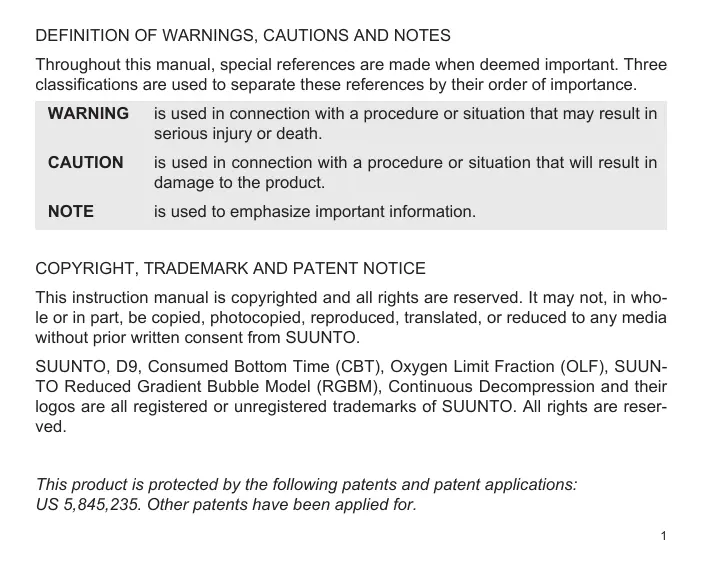
The Suunto D9 has easy-to-use push buttons and an advisory display, which guides the user. It is operated with four push buttons as follows (see Fig. 2.1.).
Mode (M) Button
Short push:
- To change from main mode to another main mode
- To exit from a sub mode to a main mode
To activate the electroluminescent backlight in the Diving mode
Long continuous push (>2 sec.):
To activate the electroluminescent backlight in the other modes
Select (S) Button
Short push:
To select a sub mode
To accept the settings in the Setting Mode
To select the active segment in the Setting Mode
- To switch page the Logbook Mode
To lock a bearing in Compass mode
To make special bookmark in the profile memory during a dive.
Long continuous push (>2 sec.):
To activate the Compass in the Watch and Dove mode.
Up (UP) Button
Short push:
- To toggle between date, second or dual time display in the Watch mode.
To change submode
To increase the value in the Setting Mode
To change dive in the Logbook Mode - To toggle between Dive time, Compass heading, Temperature, PO2, OLF%, and dive number in Dive and Compass modes
Long continuous push (>2 sec.):
To enable gas switching in Nitrox mode.
Down (DOWN) Button
Short push:
- To toggle between date, second or dual time display in the Watch mode
To change submode
To decrease the value in the Setting Mode
To change dive in the Logbook Mode - To toggle between the Max depth, Watch time, Tank pressure, and O2% in the Diving and Compass modes.
Long continuous push (>2 sec.):
To enter Settings mode
- To toggle between Ceiling and Remaining Air Time display
2.2.WATER CONTACTS
The water contacts control the automatic activation of the Dove Mode.
The water and data transfer contact is located on the right side of the case (Fig 2.2). When submerged the water contact is connected to casing (which is the other pole of the water contact) by the conductivity of the water. The "AC" symbol (Active Contacts, Fig. 2.3.) will appear on display. The AC text will be shown until the water contact deactivates.
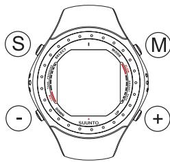
Fig. 2.1. The push buttons of the Suunto D9
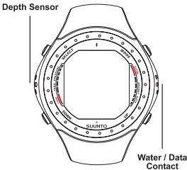
Fig 2.2. Depth sensor and water/data transfer contacts.
Contamination or dirt on the water contact may prevent this automatic operation. It is, therefore, important that the water contact is kept clean. The contact can be cleaned with fresh water and a soft brush (e.g. tooth brush).
NOTE: Water or moisture build-up around the water contact may cause the contact to activate automatically. This can happen, e.g., when washing your hands or sweating. If the water contact activates in the Time Mode, an AC symbol will appear on display (Fig. 2.3.), and it will be shown until the water contact deactivates. To save the battery power, you should deactivate the water contact by cleaning it and/or drying it with a soft towel.
2.3. OPERATING MODES
The Suunto D9 provides three main operating modes, time mode (TIME), dive mode (DIVE) and memory mode (MEM). In addition a compass mode can be activated from the TIME and DIVE modes.
The TIME mode is the default display of the instrument (Fig. 2.4.) This mode displays time, date, dual time and stopwatch.
The DIVE mode can be set to AIR, EAN or GAUGE or submodes depending on the user's diving preferences, or to OFF, which deactivates the DIVE mode.
The MEM mode provides submodes providing dive planning data (MEMplan), dive history data (MEMhis), and a dive log-book (MEMlog).
The compass submode can be called from the TIME or DIVE modes.
To toggle between the main modes press the MODE button. To select a submode in DIVE and MEM mode, press the up/ down buttons.
If a button is not pressed within 5 minutes, the dive computer beeps and returns to the time mode automatically.
2.4. WIRELESS PRESSURE TRANSMISSION
The D9 can be used together with an optional wireless cylinder pressure transmitter that can easily be attached to the high-pressure port of the regulator (Fig. 2.5). By using the transmitter the diver can benefit from cylinder pressure and remaining air time data.
In order to use the transmitter the wireless integration needs to be enabled in the D9's settings. To enable or disable the wireless integration refer to chapter 5.2.8 Tank pressure settings.
Fig.2.3. Active water contacts are indicated by the text AC
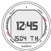
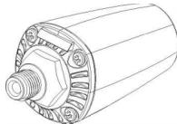
Fig. 2.4. Time mode. Pressing MODE button switches main mode.
Fig. 2.5. D9's optional wireless pressure transmitter
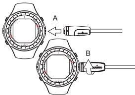
Fig. 2.6. Connecting D9's PC-interface cable. First insert the connector (A), then turn clockwise (B).
2.5. PC-INTERFACE
The Suunto D9 includes a PC-interface cable and the Suunto Dive Manager 2.0 software for analyzing and logging your dives.
The PC interface cable is connected to the right side of the Suunto D9 (fig. 2.6), and to the USB port of your PC. For instructions on how to install and use the Dove Manager Software refer to chapter 8.1 Suunto Dove Manager.
3. TIME MODE
3.1. TIME DISPLAY
The TIME mode is the default display of the instrument (Fig. 3.1) This mode displays time, date, dual time and stopwatch.
Either the date (a), the seconds of the current time (b), dual time (c) or the stopwatch (d) are shown on the bottom line of the timekeeping display. Press the up or down button to select the desired display option. The selected option will be displayed as default the next time the TIME mode is accessed.
NOTE! The seconds display is reverted to date display after 5min in order to save battery power.
The display is illuminated by holding down the M (Mode) button for more than two seconds.
When diving, the dive entry time and date is registered in the Logbook Memory. Remember always to check before diving that the time and date are correctly set, especially when traveling to different time zones.
To set the time and date, refer to chapter 3.3 "Time mode Settings".
3.2. STOPWATCH (TIMER)
The Stopwatch function is entered by pressing the UP or DOWN buttons when in TIME mode until the stopwatch display appears. (Fig. 3.1 d).
The stopwatch of the D9 lets you measure elapsed and split times. The range of the stopwatch is 99 hours, 59 minutes, 59.9 seconds (Fig. 3.2).
The stopwatch is started by pressing the DOWN button and stopped by pressing the UP button. The stopwatch is reset by pressing the UP button for >2s .
There is also a separate stopwatch (dive timer) that can be used when diving in the Gauge mode (see chapter 6.3.).
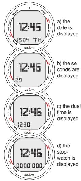
Fig. 3.1. The time keeping display
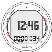
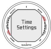
Fig. 3.2. The Stopwatch displays hours, minutes, seconds and tenths of seconds.
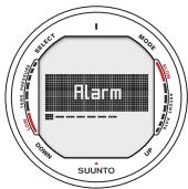
Fig. 3.3. Entering Time Settings
Fig. 3.4. Entering Daily Alarm Settings
3.3. TIME MODE SETTINGS
To enter the time mode settings press the DOWN button for >2s when in TIME mode. The display will briefly display "Time Settings" (Fig 3.3), and then display the first available setting. The settings available in TIME mode are:
- Daily alarm (Fig 3.4, 3.5)
- Time (Fig 3.6, 3.7)
- Dual time (Fig 3.8, 3.9)
- Date (Fig 3.10, 3.11)
- Units (Fig 3.12, 3.13)
- Backlight (Fig 3.14, 3.15)
- Tones (Fig 3.16, 3.17)
To toggle between available settings use the UP/DOWN buttons. Press SELECT to enter/review selected settings. Press SELECT to move between values, and UP/DOWN to change the settings. Exit by pressing the MODE button.
3.3.1. DAILY ALARM
You can set one daily alarm in the dive computer. When the daily alarm activates, the time display blinks and the alarm sounds for 24 seconds. The alarm is given at the preset time each day. Press any button to stop the audible alarm, after it has activated.
The daily alarm settings include:
- activate/deactivate daily alarm [on/off]
set the desired alarm hour [hh]
set the desired alarm minute [mm]
3.3.2. TIME
In Time/Date setting mode you are able to:
set the desired hour [hh]
set the desired minute [mm]
set the desired seconds [ss]
select 12/24h display [12/24]
3.3.3. DUAL TIME
In Dual Time setting mode you are able to:
set the desired hour [hh]
set the desired minute [mm]
3.3.4. DATE
In the Date setting mode you are able to:
set the year [yy]
set the month [mm]
set the day [dd]
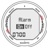
Fig. 3.5. Adjusting Daily Alarm
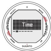
Fig. 3.6. Entering Time Settings
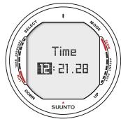
Fig. 3.7. Adjusting Time
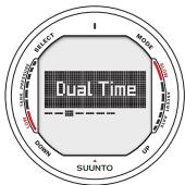
Fig. 3.8. Entering Dual Time Settings
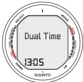
Fig. 3.9. Adjusting Dual Time
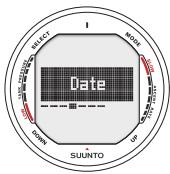
Fig. 3.10 Entering Date Settings
NOTE!
The day of the week is automatically calculated in accordance with the date.
The date can be set within the range of Jan 1, 2000 to Dec. 31, 2089.
3.3.5. UNITS
In Units setting mode you can:
- switch between metric/imperial units [metr./imp]
3.3.6.BACKLIGHT
In the Backlight Setting mode the backlight can be turned on/off and the on time can be set to be 5, 10, 20, 30 or 60seconds (Fig. 3.15.).
After entering this mode you are able to:
- switch the backlight off, or set the backlight time in seconds [off/backlight time]
NOTE! When the backlight turned OFF, it does not illuminate when an alarm is given.
3.3.7. TONES
The tones setting allows you to activate or deactivate the audible alarm. After entering this mode you are able to:
- activate/deactivate the audible alarm [on/off]
4.COMPASS MODE
The Suunto D9 is the first dive computer in the world to include a digital compass, which can be used both while diving as on the surface.
4.1. ACCESSING THE COMPASS
The compass function can be called from both the TIME and DIVE modes. To access the compass hold down the S (Select) button for >2s
The compass display will automatically return to the TIME or DIVE mode after 60s after the last button-press, in order to save battery power.
4.2. COMPASS DISPLAY
The Suunto D9 displays the compass as a graphical representation of a compass rose. The rose displays the cardinal
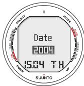
Fig. 3.11 Adjusting Date
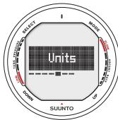
Fig. 3.12. Entering Unit Settings
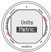
Fig. 3.13. Adjusting Units
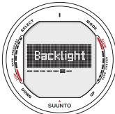
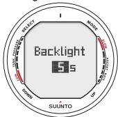
Fig. 3.14. Entering Backlight Settings
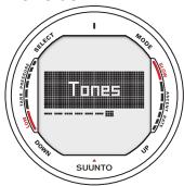
Fig. 3.15. Setting Backlight Time. Press up/down to change backlight on/off and to set time value.
Fig. 3.16. Entering Tone Settings
and half cardinal points. The current bearing is also displayed numerically. A bearing can be locked, and directional arrows point towards the locked bearing. Locking a bearing helps you e.g. follow a preferred course. Locked bearings are also stored in memory for later analysis. The locked bearing is also available the next time the compass is activated.
NOTE ! The magnetic sensor of the compass functions for 30s after the last button-press. After this the display will return to the mode it was called from (TIME or DIVE).
LOCKING A BEARING
To lock a bearing move your D9 horizontally until the intended bearing is displayed. Press SELECT to lock the bearing. The directional arrows above the compass rose will guide you towards the locked bearing as described below.
The Suunto D9 will also provide help for navigating square and triangle patterns, as well as navigating a return heading. This is indicated by a graphical symbol in the center of the compass display:
You are traveling towards the locked bearing
You are at a 90 (or 270) degree angle to the locked bearing

You are 180 degrees to the locked bearing

You are 120 (or 240) degrees to the locked bearing
4.3. COMPASS SETTINGS
To enter compass settings hold down the DOWN button for > 2s when in compass mode. Use UP/DOWN buttons to toggle between available settings, and press SELECT (S) to review/ change settings. Exit by pressing the MODE button.
4.3.1. DECLINATION
You can compensate for the difference between true north and magnetic north by adjusting the compass declination. The declination can be found, for example, from sea charts or topographic maps of your local area.
4.3.2.CALIBRATE
Because of changes in the surrounding magnetic field the D9 electronic compass occasionally needs to be re-calibrated. During the calibration process the compass adjusts itself to the surrounding magnetic field. As a basic rule, you should calibrate the compass when it does not seem to operate properly, or after replacing the D9 battery.
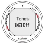
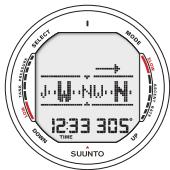
Fig. 3.17. Setting Tones
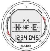
Fig. 4.1. Compass Display (from TIME mode). Current heading is North West, 305 degrees. Locked bearing is on the right side.
Fig.4.2. Pressing Select (S) locks the current bearing, 45 degrees North East 31
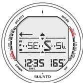
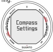
Fig. 4.3. Triangle indicates that you are 120 degrees to the right from the locked bearing.
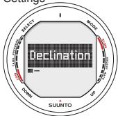
Fig. 4.4. Entering Compass Settings
Fig. 4.5. Entering Declination Settings
Strong electromagnetic fields, such as powerlines, loudspeakers and magnets can affect the compass calibration. It is therefore advisable to calibrate the compass if the D9 has been exposed to these fields.
NOTE! It is recommended to calibrate the compass before using it at a new location.
NOTE! Remember to hold the Suunto D9 level during the calibration
To calibrate the compass:
- Enter Calibration mode (Fig 4.7)
- The display will briefly say "Rotate 360" (Fig. 4.8a)
- Hold the Suunto D9 level and slowly rotate the device in a full circle. The animated circle on the display represents the progress of the calibration (Fig 4.8b)
- If the calibration succeeds the "Passed" message is displayed (Fig 4.8.c) and the compass is calibrated and ready for use. If the calibration fails, a "Try again" message is given (Fig 4.8d).
If the calibration fails several times in a row, it may be possible that you are in an area with sources of magnetism, such as large metal objects, powerlines or electric appliance. Move to another location and try to calibrate the compass again.
If the calibration continues to fail, contact an authorized Suun-to service center.
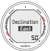
Fig. 4.6. Setting Declination
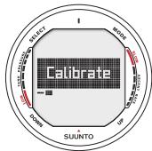
Fig. 4.7. Entering Compass Calibration
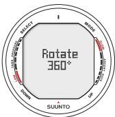
Fig. 4.8. Compass Calibration
a) Hold the Suunto D9 level, and slowly rotate 360 degrees
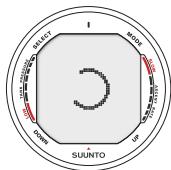
b) Graph indicates progress during rotation
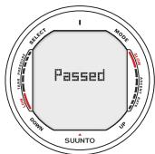
c) Compass properly calibrated and ready for use
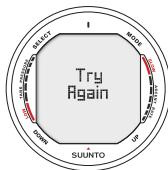
d) Calibration failed, try again.
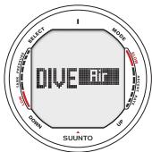
Fig. 5.1 Dove Modes
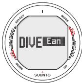
a) Air mode
b) Nitrox Mode
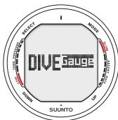
c) Gauge Mode
5. BEFORE DIVING
5.1. ACTIVATION AND PRECHECKS
The Suunto D9 has three diving modes: Air mode (Fig 5.1a) for diving with standard air only, Nitrox mode (Fig 5.1b) for diving with oxygen enriched mixtures and Gauge mode (Fig 5.1c) for use as bottomtimer and for freediving. The Off mode (Fig 5.1d) disables the dive mode, and allows the watch mode to be used underwater. The chosen dive mode is displayed when the DIVE mode is accessed.
5.1.1. DIVE MODE ACTIVATION
The dive computer will activate if submerged deeper than 0.5 m (1.5 ft). However, it is necessary to activate the Dive Mode before diving to check the cylinder pressure, altitude and personal adjustment settings, battery condition, oxygen settings etc. Press the Mode button to switch to the default DIVE mode. To change the DIVE mode press Up or Down button. The chosen dive mode is activated after a few seconds, or by pressing Select.
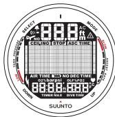
After activation all display elements will turn on showing mostly figure 8's and graphical elements, and the backlight and the buzzer are activated (Fig. 5.2.). After this the selected altitude
and personal settings are displayed (Fig. 5.3) A few seconds later the battery power indicator is shown (Fig. 5.4.)
At this time, perform your prechecks making sure that:
the instrument operates in the correct mode and provides a complete display (Air/Nitrox/Gauge mode)
the battery level is ok
- the altitude, personal adjustment, safety/deep stops and RGBM settings are correct
the instrument displays correct units of measurement (Metric/Imperial)
the instrument displays correct temperature and depth (0.0 m [0 ft])
the buzzer beeps
If the optional wireless pressure transmitter is used (see chapter 2.4. Wireless pressure transmission) ensure that:
- the pressure transmitter has been properly attached and that the cylinder valve is open
- the transmitter and the wrist unit have been properly paired on a suitable code
- the pressure transmitter is working (lightning symbol blinks, cylinder pressure is displayed), and that there is no low battery warning displayed
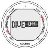
d) Off Mode, Diving Mode disabled
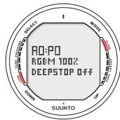
Fig. 5.2. Startup. All segments shown.
Fig. 5.3. Altitude and personal settings.
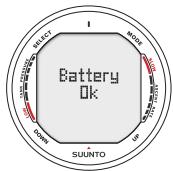
Fig. 5.4 Battery check:
a) Battery ok
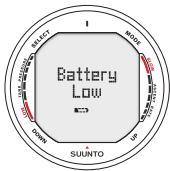
b) Battery Low
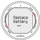
c) Battery should immediately be replaced
- you have enough air for your planned dive. You should also check the pressure reading against your back-up pressure gauge.
And if set to Nitrox mode (refer to chapter 6.2 Diving in Nitrox mode), make sure that:
- the correct number of mixes are set and that the oxygen percentages are adjusted according to the measured Nitrox blends in your cylinders
the oxygen partial pressure limits are set correctly.
The dive computer is now ready for diving (Fig. 5.5).
5.1.2. BATTERY POWER INDICATION
Temperature or an internal oxidation of the battery affects the battery voltage. If the instrument is stored for a long period, the low battery warning may be displayed even though the battery has enough capacity. The low battery warning may also be displayed at low temperatures, even though the battery has enough capacity in warmer conditions. In these cases repeat the battery check procedure.
After the battery check the Low Battery Warning is indicated by the battery symbol (Fig. 5.6.).
If the battery symbol is displayed in the Surface mode or if the
display is faded or weak, the battery may be too low to operate the dive computer and battery replacement is recommended.
NOTE! For safety reasons the backlight cannot be activated when the low battery warning is indicated by the battery symbol.
The optional wireless pressure transmitter sends out a lowbat (LOBT) warning when its battery voltage is getting low. This is shown intermittently instead of the pressure reading (see chapter 5.3, Fig 5.30). When you get this warning the pressure transmitter battery needs to be replaced.
5.1.3. DIVING AT ALTITUDE
The dive computer can be adjusted both for diving at altitude and also to increase the conservatism of the mathematical nitrogen model.
When programming the instrument for the correct altitude, you need to select the correct Altitude Mode according to Table 5.1. The dive computer will adjust its mathematical model according to the entered altitude mode, giving shorter nodecompression times at higher altitudes (see Section 10.2, Table 10.1. and 10.2.).
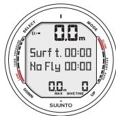
Fig 5.5. Surface mode. Depth and dive time are zero.
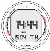
Fig. 5.6. Low Battery Warning. Battery symbol indicates that the battery is low and battery replacement is recommended.
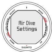
Fig. 5.7. Entering Air
Dive Settings
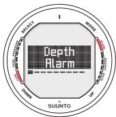
Fig. 5.8. Entering Depth Alarm settings
TABLE 5.1. ALTITUDE ADJUSTMENT RANGES
| Altitude Mode | Altitude Range |
| A0 | 0-300m [0-1000ft] |
| A1 | 300-1500m [1000-5000ft] |
| A2 | 1500-3000m [5000-10000ft] |
Section 5.2.4. "Altitude Adjustment and Personal Adjustment Setting" describes how the Altitude Mode is adjusted.
Traveling to a higher elevation can temporarily cause a change in the equilibrium of dissolved nitrogen in the body. It is recommended that you acclimate to the new altitude by waiting at least three hours before making a dive.
5.1.4. PERSONAL ADJUSTMENTS
There are adverse personal factors for DCI which divers can predict in advance and input into the decompression model. Factors that may affect susceptibility to decompression illness vary between divers and also for the same diver from one day to another. The three-step Personal Adjustment Mode is available, if a more conservative dive plan is desired. For very experienced divers, a two step adjustment for RGBM effect on repetitive dives is available.
The personal factors which tend to increase the possibility of DCI include, but are not limited to:
- cold exposure - water temperature less than 20^ [68 F]
- the diver is below average physical fitness level
diver fatigue
diver dehydration - previous history of DCI
- stress
-obesity
Section 5.2.4. "Altitude Adjustment and Personal Adjustment Setting" describes how the Personal Mode is adjusted.
This feature should be used to adjust the computer to be more conservative, according to personal preference, by entering the suitable Personal Adjustment Mode with the help of Table 5.2. In ideal conditions, retain the default setting, P0. If conditions are more difficult or other mentioned factors which tend to increase the possibility of DCI exist, select P1 or even the most conservative P2. As a result the dive computer adjusts its mathematical model according to the entered Personal Adjustment Mode, giving shorter no-decompression times (see Section 10.2, Table 10.1. and 10.2.).
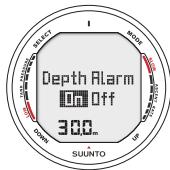
Fig. 5.9. Setting Maximum Depth Alarm. Press the UP/DOWN buttons to change alarm on/off and to set maximum depth value.
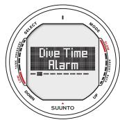
Fig. 5.10. Entering Dive Time Alarm settings
TABLE 5.2. PERSONAL ADJUSTMENT RANGES
| Personal Mode | Condition |
| P0 | Ideal conditions |
| P1 | Some mentioned factors or conditions exist |
| P2 | Several mentioned factors or conditions exist |
The D9 also allows experienced divers who are willing to accept a greater level of risk to adjust the RGBM model. The default setting is 100% which gives full RGBM effect. Suunto strongly advises to use full RGBM effect. Statistically very experienced divers have less incidents with DCI. The reason for this is unknown, but it is possible that some level of physiological and or psychological accommodation can take place when you are very experienced as a diver. Thus for certain divers and diving conditions you may want to set attenuated (50%) RGBM mode. See Table 5.3.
TABLE 5.3 RGBM MODEL SETTINGS.
| RGBM setting | Desired tables | Effect |
| 100% | Standard Suunto RGBM model (Default) | Full RGBM effects |
| 50% | Attenuated RGBM model | Smaller RGBM effects, higher risk! |
5.1.5. SAFETY STOPS
Safety stops are widely considered "good diving practice" for recreational diving and are an integral part of most dive tables. Reasons to perform a safety stop include a reduction in sub clinical DCI, microbubble reduction, ascent control, and orientation before surfacing.
The D9 displays two different types of safety stops: Recommended Safety Stop and Mandatory Safety Stop.
Recommended Safety Stop
With every dive over 10 meters there is a three minute countdown for the recommended safety stop, to be taken in the 3 - 6 meter [10 ft - 20 ft] range. This is shown with the STOP sign and a three-minute countdown in the center window instead of the no-decompression time (Fig. 6.7.).
The Recommended Safety Stop, as the name implies, is recommended. If it is ignored, there is no penalty applied to the following surface intervals and dives.
Mandatory Safety Stop
When the ascent rate exceeds 12 meters/min [40 ft] momentarily or 10 meters/min [33ft] continuously the micro-bubble build-up is predicted to be more than allowed for in the de
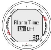
Fig. 5.11. Setting Dove Time Alarm. Press up/down buttons to change alarm on/off and to set dive time value. Press Select to accept/ move to next setting.
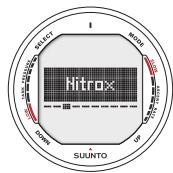
Fig. 5.12. Entering Nitrox settings
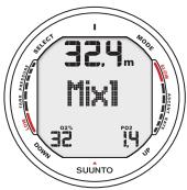
Fig. 5.13. Setting primary gas mix (MIX1). Oxygen percentage is 32% , oxygen partial pressure limit is 1.4 bar. The equivalent maximum depth is displayed as 32.4 m [106 ft]. Press scroll buttons to change oxygen percentage and to set oxygen partial setting value. Accept settings by pressing SELECT.
compression model. The Suunto RGBM calculation model responds to this by adding a Mandatory Safety Stop to the drive. The time of this Mandatory Safety Stop will depend on the severity of the ascent rate excess.
The STOP sign will appear in the display and when you reach the depth zone between 6 m to 3 m [20 ft to 10] also the CEILING label, ceiling depth and the calculated Safety Stop time appear in the display. You should wait until the Mandatory Safety Stop warning disappears (Fig. 6.8.). The total length of the Mandatory Safety Stop time depends on the seriousness of the ascent rate violation.
You must not ascend shallower than 3m [10 ft] with the Mandatory Safety Stop warning on. If you ascend above the Mandatory Safety Stop ceiling, a downward pointing arrow will appear and a continuous beeping starts (Fig. 6.13.). You should immediately descend to, or below, the Mandatory Safety Stop ceiling depth. If you correct this situation at any time during that dive, there are no affects on the decompression calculations for future dives.
If you continue to violate the Mandatory Safety Stop, the tissue calculation model is affected and the dive computer shortens the available no-decompression time for your next dive.
In this situation, it is recommended to prolong your surface interval time before your next dive.
5.1.6. DEEP STOPS
The Suunto D9 allows the user to choose a Deep Stop algorithm instead of the traditional recommended safety stop. Deep Stops are decompression stops that occur deeper than traditional stops, with the purpose of minimizing microbubble formation and excitation.
The Suunto RGBM model calculates deep stops iteratively, placing the first stop about halfway between the maximum depth and the ceiling depth. After the first deep stop is completed, another deep stop will be prompted halfway to the ceiling, and so on until the ceiling depth is reached.
The deep stop length can be set to 1 or 2 minutes.
Enabling the Deep Stops disables the Recommended Safety Stops, but Mandatory Safety Stops due to e.g. continuous ascent rate violations are still prompted.
Fig. 5.14. Setting additional gas mixes (MIX2, MIX3).
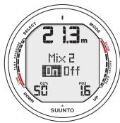
a) MIX 2 is turned on. Oxygen percentage is 50% oxygen partial pressure limit is 1.6 bar. Maximum Operational Depth is 21.3m Press scroll buttons to enable/ disable MIX2. Press SE-LECT to accept settings.
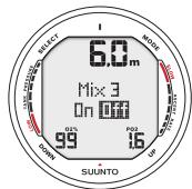
b) Mix 3 is set off. Oxygen percentage is 99% oxygen partial pressure limit is 1.6. Maximum Operational Depth is 6m
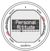
Fig. 5.15. Entering Personal and Altitude settings.
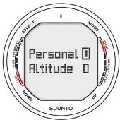
Fig. 5.16. Setting Personal and Altitude adjustment. Press scroll buttons to change personal mode. Use SELECT to accept.
5.2. DIVE MODE SETTINGS
This D9 has several User Definable Functions and depth and time related alarms that you can set according to your personal preference. The dive mode settings are dependent on the DIVE sub-mode chosen (Air, EAN, Gauge), so that e.g. nitrox settings are only available in the DIVEean sub-mode.
To enter dive mode settings (Fig. 5.7) press the DOWN button for >2s when in DIVE mode. Then use the UP/DOWN buttons to toggle settings. Press SELECT to review/change settings. Use SELECT to move between values and UP/DOWN to alter the value. Exit using MODE.
NOTE! The settings cannot be activated until 5 minutes has elapsed after the dive.
5.2.1. DEPTH ALARM
You can set one depth alarm in the dive computer (Fig 5.8). The depth alarm is set to 40m [131 ft] at the factory, but you are able to adjust it according your personal preference or switch it off. The depth range can be set from 3.0m to 100m [9 ft to 328 ft] (Fig. 5.9.).
5.2.2.DIVE TIME ALARM
The instrument has one Dove Time Alarm Setting, which can be used for several purposes to add to your diving safety (Fig 5.10). The alarm can be set, for example, to your planned bottom time. The Dove Time alarm can be set on or off and the time from 1 to 999 minutes (Fig.5.11).
5.2.3. NITROX SETTINGS
If set to the Nitrox mode, the correct oxygen percentage of the gas in your cylinder (and additional gases) must always be entered into the computer to ensure correct nitrogen and oxygen calculations. Also, in Nitrox mode, the oxygen partial pressure limit must be set. When in the Nitrox Setting mode the equivalent allowed maximum depth based on the chosen setting will also be displayed. Settings for additional mixes (MIX2, MIX3) are made similarly but with the selection of "ON" or "OFF" for these.
In order to minimize the risk of error during the dive it is highly recommended that the mixes are set with proper order. This means that as the mix number rises so does oxygen content and this is the order they are usually used during the dive. Before a dive set "on" only the mixes you actually have available and remember to check the set values so they are correct.
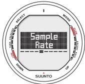
Fig. 5.17 Entering Sample Rate settings
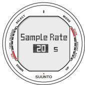
Fig. 5.18 Setting Sample Rate. Press scroll buttons to change sample rate.
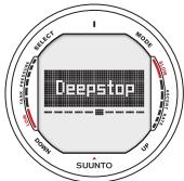
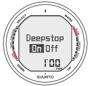
Fig. 5.19. Entering Deepstop settings
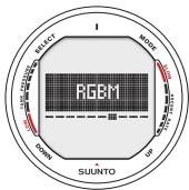
Fig. 5.20 Setting Safety/ Deep stops. Press up/down buttons to change settings.
Fig. 5.21 Entering RGBM adjustment.
The default oxygen percentage (O_2%) setting is 21% (air) and oxygen partial pressure (PO_2) setting 1.4 bar. After entering values for MIX1 you can enable/disable and set additional gas mixes MIX2 and MIX3 (Fig. 5.12-5.14).
NOTE! If only MIX 1 is enabled (MIX2/3 set OFF), MIX1 will revert to default settings (21% O_2 and PO_2 1.4 bar) after approximately 2 hours. If either MIX2 or MIX3 are set ON, settings for all mixes are stored until changed,
5.2.4. PERSONAL/ALTITUDE SETTINGS
The current Altitude and Personal Adjustment modes are displayed in the startup screen when entering the diving mode. If the mode does not match the altitude or personal conditions (see sections 5.1.3 and 5.1.4), it is imperative that you enter the correct selection before diving. Use the Altitude Adjustment to select the correct altitude mode. Use the Personal Adjustment to add an extra level of conservatism.
5.2.5. SAMPLING RATE
The sampling rate controls how often the depth, time tank pressure and water temperature is stored in memory. You can set dive profile sample rate to 1, 10, 20, 30 or 60 seconds. The factory default setting is 20 seconds.
5.2.6. SAFETY STOPS/DEEPSTOPS
The deepstop setting allows the user to choose between traditional safety stops or deep stops. If Deepstops are set to OFF, traditional safety stop calculation is used. If set to ON, iterative Deepstops will be prompted instead. The length of the individual deepstops can be set to 1 or 2 minutes.
5.2.7. RGBM SETTINGS
For certain divers and diving conditions you may want to set attenuated RGBM mode. The selection is displayed during the dive mode startup. The options are full RGBM effects (100%), and attenuated RGBM (50%).
5.2.8. TANK PRESSURE
The wireless transmission can be set "ON" or "OFF" depending on if the optional wireless pressure transmitter is used or not. No cylinder pressure related data is shown or data reception made when this selection is "off".
You can set the secondary cylinder pressure alarm point. The 50 bar alarm is fixed and cannot be changed. The 35 bar secondary alarm pressure can be set in the range 10 -200bar.
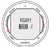
Fig. 5.22 Setting RGBM adjustment. Press up/down to change setting.
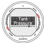
Fig. 5.23 Entering Tank pressure settings
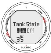
Fig. 5.24 Wireless intergartion disabled (off), press up/down to activate. Tank pressure alarm is currently set to 35bar pressure.
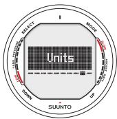
Fig. 5.25. Entering Unit settings
5.2.9. UNITS
You can choose between metric (meters/celcius/bar) and imperial (feet/farenheit/psi) units. (Fig. 5.26.).
5.2.10. HP CODE
The HP Code setting allows the user to verify the selected code and to erase the stored code and enable re-pairing if needed.
5.3. WIRELESS TRANSMISSION SETUP
5.3.1. INSTALLING THE WIRELESS TRANSMITTER
Upon purchasing the D9, Suunto strongly recommends you have your dealer attach the transmitter to the first stage of your regulator.
If you decide to attach it yourself, follow the steps outlined below:
- Remove the high pressure (HP) port plug on the first stage of your regulator using an appropriate tool.
- Thread the high pressure transmitter of the D9 into the HP port of your regulator with your fingers. DO NOT OVERTIGHTEN! Maximum torque 6 Nm (4.4
ftlbs or 53 inlbs). Sealing is based on a static o-ring, not force!
- Attach the regulator to the scuba cylinder. Slowly open the valve. Check for leaks by submerging the regulator first stage in water. If leaks are detected, check the condition of the o-ring and sealing surfaces.
5.3.2. PAIRING AND CODE SELECTION
In order to receive wireless data the transmitter and the D9 wrist unit need to be paired. During the pairing procedure the transmitter and wrist unit select a common transmission code.
The transmitter turns on when the pressure exceeds 15bar [218 psi] and it then starts sending pressure data together with a code number. During the pairing procedure the D9 stores the above mentioned code number and starts displaying pressure values that are received with that code. This coding procedure inhibits data mix up from other divers also using the D9's transmitter.
When there is no stored code the D9 will display "cd:--" and receive with lowered sensitivity from a very short distance only (Fig. 5.30 a). By taking the D9 close to the transmitter it will
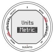
Fig. 5.26 Setting Metric/ Imperial units.
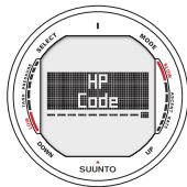
Fig. 5.27. Entering HP Code settings
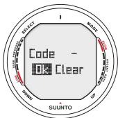
Fig. 5.28 No code stored, unit ready for pairing with transmitter
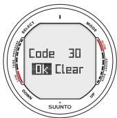
Fig. 5.29 Unit is paired on channel 32. Select Clear to erase code, OK to accept.
store the received code and start receiving with full sensitivity and display data received with this code only. The code is held stored for approximately 2 hours, or until the cylinder pressure goes below 10 bar [145 psi]. The set code can also be manually erased by the user.
To pair the transmitter and the wrist unit:
- Make sure that the transmitter is properly attached to the regulators HP port and that the regulator is properly attached to the cylinder.
- Ensure that the D9 is turned on, an that the wireless integration is enabled in the D9's settings (HP set on, see chapter 5.2.8). The D9 should display "cd:--" in the lower left corner of the alternative display.
- Slowly open the cylinder valve fully and pressurize the regulator. The transmitter will start transmitting when the pressure exceeds 15bar [218 psi].
- Take the D9 wrist unit close to the transmitter. The D9 will now shortly display the selected code number and then start displaying the transmitted cylinder pressure. A lightning symbol will be displayed every time the D9 receives a valid signal.
WARNING: In case there are several divers using D9s with wireless transmission always ensure that all divers are on different codes before starting the dive.
The user can manually change the transmitters code by reducing the pressure to less than 10 bar [145 psi] and then immediately (within 10-12s) increasing the pressure above 15 bar [220 psi]. The transmitter will now select a new code. The wrist unit must be in cd:-- mode to pair on the new code. This procedure can be used e.g. if your dive buddy has the same code and you need to change the code.
NOTE: In order to save battery energy the transmitter shuts off if the pressure remains unchanged for more than 5 minutes and it will continue transmitting with the saved code when any pressure change is measured.
5.3.3. TRANSMISSION DATA
After the pairing procedure the D9 will receive cylinder pressure data from the transmitter. The pressure is displayed in either bars or psi depending on the unit selection. Any time the D9 receives an appropriate signal it flashes the lightning figure in the display's lower left corner. A pressure reading of over 360 bar [5220 psi] will display as "---" (Fig. 5.30 b).
If the D9 is unable to receive a valid signal for more than one minute it will start displaying "FAIL" intermittently with the latest valid pressure reading (Fig. 5.30 c).
In case the transmitter battery is running low, a low battery warning "LOBT" will be transmitted and displayed intermittently with the pressure reading on the D9 (Fig. 5.30 d).
If the dive is started without that the D9 and the transmitter have been properly paired, the D9 will indicate that no cylinder data is available by displaying "OFF" (Fig. 5.30e).
TABLE 5.3. PRESSURE TRANSMISSION RELATED DISPLAYS
| Display | Indication | Figure 5.30 |
| Cd:-- | Set Code. No code stored, wrist unit ready for pairing with transmitter. | a |
| ---- | Pressure reading over 360 bar [5220 psi] | b |
| FAIL | Indicates pressure reading has not been updated in more than 1 minute. Transmitter is out of range, in power saving mode or on another channel. Activate the transmitter by breathing off the regulator, and recode the wrist unit if necessary. | c |
| LOBT | Indicates pressure transmitter battery voltage is low. Change the transmitter battery! | d |
| OFF | Pairing has not been conducted before start of dive. No cylinder data available. | e |
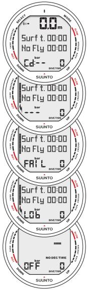
Fig 5.30. Pressure transmission related displays
a) Set code
b) Overpressure
c) Fail
d) Low battery
e) Off
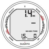
Fig. 6.1. Dove has just begun and available no-decompression time is over 99min
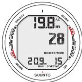
Fig. 6.2. Diving display. Present depth is 19.8m [66 ft] and no-decompression stop time limit is 28 minutes. Maximum depth during this dive was 20.9m [70 ft], elapsed dive time is 15 minutes.
6. DIVING WITH THE SUUNTO D9
This section contains instructions on how to operate the dive computer and interpret its displays. You will find that this dive computer is easy to use and read. Each display shows only the data relevant to that specific diving situation.
6.1. DIVING IN AIR MODE [DIVEAIR]
The D9 has three diving modes: Air mode (DIVEair) for diving with standard air only, Nitrox mode (DIVEean) for diving with oxygen enriched mixtures and Gauge mode (DIVEgauge) for use as bottomtimer and for freediving. The chosen dive mode is displayed when the DIVE mode is accessed.
NOTE! The dive computer will remain in the Surface mode at depths less than 1.2m [4 feet]. At depths greater than 1.2m the instrument will go into the Diving mode (Fig. 6.1.).
6.1.1. BASIC DIVE DATA
All information on the display is labeled (Fig. 6.2.). During a no-decompression stop dive, the following information will be displayed:
- your present depth in meters [ft]
-
the available no-decompression time in minutes as NO DEC TIME
-
the ascent rate by a bar graph on the right side
- the Diver Attention Symbol if surface interval should be prolonged (see Table 6.1.)
Alternative displays by pressing the UP/DOWN buttons:
- the elapsed dive time in minutes, shown as DIVE TIME
- the water in temperature in ^ C [°F]
- the maximum depth during this dive in meters [ft], indicated as MAX
- the current time, shown as TIME
In addition with the optional wireless transmission enabled:
- the Remaining Air-time in the left center window inci-cated as AIR TIME
- the cylinder pressure in bar [or psi] displayed in the lower left corner
- the cylinder pressure graphically on the left side
6.1.2. BOOKMARK
It is possible to make special marks in the profile memory during a dive. These Bookmarks will be displayed when scrolling the profile memory on the computer display. The Bookmarks will also be shown as annotations in the PC-software, Suun
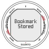
Fig. 6.3. Bookmark activation. An annotation, Bookmark, is placed in the profile memory during a dive by pressing SELECT button.
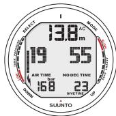
Fig. 6.4 Diving Display. Current tank pressure is 168bar and remaining air time is 19min.
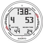
Fig. 6.5. Cylinder pressure warnings. Pressure has dropped below 50 bar [725 psi]. Pressure display is blinking and there is an audible alarm.
to Dive Manager. The bookmark logs the depth, time and water temperature as well as compass heading and tank pressure when available. To make a bookmark in the profile memory during a dive press the SELECT button. A brief confirmation will be given (Fig. 6.3.).
6.1.3. TANK PRESSURE DATA
When using the optional wireless pressure transmitter the pressure of your scuba cylinder in bars [psi] will be shown digitally in the lower left corner of the alternative display (Fig. 6.4). Anytime you enter into a dive, the remaining air time calculation begins. After 30 - 60 seconds (sometimes more, depending on your air consumption), the first estimation of remaining air time will be shown in the left center window of the display. The calculation is always based on the actual pressure drop in your cylinder and will automatically adapt to your cylinder size and current air consumption.
The change in your air consumption will be based on constant one second interval pressure measurements over 30 - 60 second periods. An increase in air consumption will influence the remaining air time rapidly, while a drop in air consumption will increase the air time slowly. Thus a too optimistic air time estimation, caused by a temporary drop in air consumption, is avoided.
The remaining air time calculation includes a 35 bar [500 psi] safety reserve. This means that when the instrument shows the air time to be zero, there is still about 35 bar [500 psi] pressure left in your cylinder depending on your air consumption rate. With a high consumption rate the limit will be close to 50 bar [725 psi] and with a low rate close to 35 bar [500 psi].
NOTE! Filling your BC will affect the air time calculation, due to the temporary increase in air consumption.
NOTE! A change of temperature will affect the cylinder pressure and consequently the air time calculation.
Low Air PressureWarnings
The dive computer will warn you with three audible double beeps and a blinking pressure display when the cylinder pressure reaches 50 bar [725 psi] (Fig. 6.5.). Three double beeps are also heard when the cylinder pressure goes down to the user selected alarm pressure and when the remaining air time reaches zero.
6.1.4. ASCENT RATE INDICATOR
The ascent rate is shown graphically along the right side of the display as follows:

Fig. 6.6. Ascent Rate Indicator. Audible alarm, activated backlight and a blinking full ascent rate bar graph indicate that ascent rate is more than 10m / min [33 ft/min]. This is a caution to slow down! STOP sign means that you are advised to make a Mandatory Safety Stop when you reach a depth of 6m [20 ft].
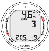
Fig 6.7 Recommended Safety Stop. You are advised to make a Recommended Safety stop for 3 minutes.
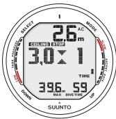
Fig. 6.8. A Mandatory Safety Stop. You are advised to make a one minute Mandatory Safety Stop in the depth zone between 6m and 3m [20 ft and 10 ft].
When the maximum allowed ascent rate is exceeded, the fifth SLOW warning segment and the STOP sign appear and the depth reading starts to blink, indicating that the maximum ascent rate has been exceeded continuously or that the current ascent rate is significantly above the allowed rate (Fig. 6.6).
WARNING!
DO NOT EXCEED THE MAXIMUM ASCENT RATE! Rapid ascents increase the risk of injury. You should always make the Mandatory and Recommended Safety Stops after you have exceeded the maximum recommended ascent rate. If this Mandatory Safety Stop is not completed the decompression model will penalize your next dive(s).
6.1.5. SAFETY STOPS AND DEEP STOPS
If Deep Stops are not used a 3 minute Recommended Safety Stop is prompted after every dive to over 10m depth (Fig. 6.7). Continuous ascent rate violations will result in Mandatory Safety Stops (fig. 6.8). When enabled, Deepstops are calculated. The lenght of the recommended Deep Stop is indicated in seconds (Fig. 6.9).
6.1.6. DECOMPRESSION DIVES
When your NO DEC TIME becomes zero, your dive becomes a decompression stop dive, i.e. you must perform one or several decompression stops on your way to the surface. The NO DEC TIME on your display will be replaced by an ASC TIME and a CEILING notation will appear. An upward pointing arrow will also prompt you state your ascent (Fig. 6.10.).
If you exceed the no-decompression limits on a dive, the dive computer will provide decompression information required for ascent. After this, the instrument will continue to provide subsequent interval and repetitive dive information.
Rather than requiring you to make stops at fixed depths, the dive computer lets you to decompress within a range of depths (Continuous Decompression).
The ascent time (ASC TIME) is the minimum amount of time needed to reach the surface in a decompression dive. It includes:
the time needed to ascend to the ceiling at an ascent rate of 10m / min [33 ft/min]
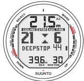
Fig. 6.9 Deepstop. You are advised to make a deepstop at 21m . The second indicator shows that you have 44 seconds left of your deepstop.
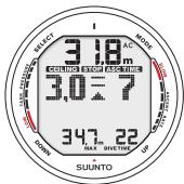
Fig. 6.10. Decompression on dive without deepstops, below floor. Upward pointing arrow, blinking ASC TIME label and an audible alarm tell you to ascend. Minimum total ascent time including safety stop is 7 minutes. Ceiling is at 3 m [10 ft].
plus
- the time needed at the ceiling. The ceiling is the shallowest depth to which you should ascend
plus
the time needed at the Mandatory Safety Stop (if any)
- the time needed to reach the surface after the ceiling and safety stops have been completed.
WARNING!
YOUR ACTUAL ASCENT TIME MAY BE LONGER THAN DISPLAYED BY THE INSTRUMENT! The ascent time will increase if you:
- remain at depth
- ascend slower than 10m / min [33 ft/min] or
- make your decompression stop deeper than at the ceiling.
These factors will also increase the amount of air required to reach the surface.
CEILING, CEILING ZONE, FLOOR AND DECOMPRESSION RANGE
When in decompression, it is important that you understand the meaning of ceiling, floor, and decompression range (Fig. 6.14.):
- The ceiling is the shallowest depth to which you should ascend when in decompression. At this depth, or below, you must perform all stops.
- The ceiling zone is the optimum decompression stop zone. It is the zone between the minimum ceiling and 1.8m [6 ft] below the minimum ceiling.
- The floor is the deepest depth at which the decompression stop time will not increase. Decompression will start when you pass this depth during your ascent.
- The decompression range is the depth range between the ceiling and floor. Within this range, decompression takes place. However, it is important to remember that the decompression will be very slow at, or close to, the floor.
The depth of the ceiling and floor will depend on your dive profile. The ceiling depth will be fairly shallow when you enter the decompression mode, but if you remain at depth, it will
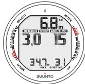
Fig. 6.11. Decompression dive, above floor. Upward pointing arrow has disappeared and ASC TI-ME label has stopped blinking, which means that you are in the decompression range.
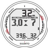
Fig. 6.12. Decompression dive, at ceiling zone. Two arrows point at each other ("hour glass"). You are in the optimum ceiling zone at 3.2m [11 ft] and your minimum ascent time is 7 minutes...
move downward and the ascent time will increase. Likewise, the floor and ceiling may change upwards while you are de-compressing.
When conditions are rough, it may be difficult to maintain a constant depth near the surface. In this case it will be more manageable to maintain an additional distance below the ceiling, to make sure that the waves do not lift you above the ceiling. Suunto recommends that decompression takes place deeper than 4m [13 ft], even if the indicated ceiling is shallower.
NOTE! It will take more time and more air to decompress below the ceiling than at the ceiling.
WARNING!
NEVER ASCEND ABOVE THE CEILING! You must not ascend above the ceiling during your decompression. In order to avoid doing so by accident, you should stay somewhat below the ceiling.
DISPLAY BELOW THE FLOOR
The blinking ASC TIME and an upward pointing arrow indicate that you are below the floor (Fig. 6.10.). You should start your ascent immediately. The ceiling depth is shown on the left side and the minimum total ascent time on the right side of the center window.
DISPLAY ABOVE THE FLOOR
When you ascend above the floor, the ASC TIME display stops blinking and the upward pointing arrow disappears (Fig. 6.11.). Decompression will now begin, but is very slow. You should therefore continue your ascent.
DISPLAY AT THE CEILING ZONE
When you reach the ceiling zone, the display will show you two arrows pointing at each other (the "hour glass" icon, Fig 6.12.). Do not ascend above this zone.
During the decompression stop, ASC TIME will count down towards zero. When the ceiling moves upwards, you can ascend to the new ceiling. You may surface only after the ASC TIME and CEILING labels have disappeared, which means that the decompression stop and any Mandatory Safety Stop has been completed. You are advised, however, to stay until the STOP sign has also gone. This indicates that the three minute Recommended Safety Stop has also been completed.
DISPLAY ABOVE THE CEILING
If you ascend above the ceiling during a decompression stop, a downward pointing arrow will appear and a continuous beeping starts (Fig. 6.13.). In addition, an error warning Er reminds you that you have only three minutes to correct the
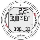
Fig. 6.13. Decompression on dive, above ceiling. Note downward pointing arrow, Er warning and an audible alarm. You should immediately (within 3 minutes) descend to or below ceiling.
situation. You must immediately descend to or below the ceiling.
If you continue to violate the decompression, the dive computer goes into a permanent Error Mode. In this mode the instrument can only be used as a depth gauge and timer. You must not dive again for at least 48 hours (see also section 6.7. "Error Conditions").
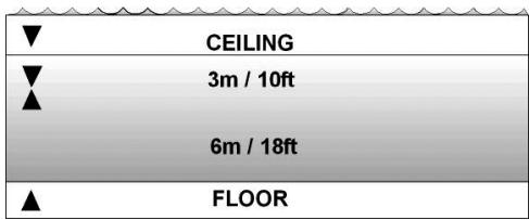
Fig. 6.14. Ceiling and Floor Zones. The Recommended and Manadulatory Safety Stop zone lies between 6m and 3m [20 ft and 10ft].
6.2. DIVING IN NITROX MODE [DIVEEAN]
6.2.1. BEFORE DIVING IN NITROX MODE
If set to the Nitrox mode (DIVEean), the correct oxygen percentage of the gas in your cylinder must always be entered into the computer to ensure correct nitrogen and oxygen calculations. The dive computer adjusts its mathematical nitrogen and oxygen calculation models. The dive computer will not accept fractional percentage values of oxygen concentration. Do not round up fractional percentages. For example, 31.8% oxygen should be entered as 31% . Rounding up will cause nitrogen percentages to be understated and will affect decompression calculations. If there is a desire to adjust the computer to provide more conservative calculations, use the personal adjustment feature to affect decompression calculations or reduce the PO_2 setting to affect oxygen exposure according to the entered O_2% and PO_2 values. Calculations based on Nitrox use result in longer no-decompression times and shallower maximum depths than diving with air.
As a safety precaution the oxygen calculations in the computer are made with an oxygen percentage of 1% + setO_2% .
When the dive computer is set in Nitrox mode also the Dive Planning mode calculates with the O_2% and PO_2 values that
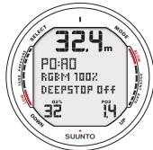
Fig. 6.15. Nitrox Dove Mode Activation. Maximum Operational Depth based on set O2% (32%) and PO2 (1.4 bar) is 32.4m].
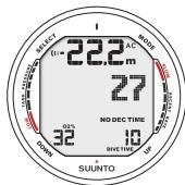
Fig. 6.16. Diving in Nitrox mode. Set 02% is 32% .
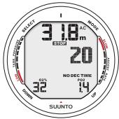
Fig. 6.17. PO2 Display, Oxygen Partial Pressure is 1.4 bar
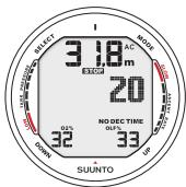
Fig. 6.18.OLF Display. Oxygen Limit Fraction (OLF) has reached 33% limit.
are currently in the computer.
To set the Nitrox mixes refer to chapter 5.2.3 Nitrox settings.
DEFAULT NITROX SETTINGS
In Nitrox mode the D9 allows the user to set 1-3 nitrox mixes containing 21 - 99% oxygen.
In the Nitrox mode, the default setting for MIX1 is standard air (21% O_2) . It remains in this setting until the O_2% is adjusted to any other percentage of oxygen (22% - 100%). The default setting for maximum oxygen partial pressure is 1.4 bar, however you are able to set it in the range of 0.5 - 1.6 bar.
MIX2 and MIX3 are by default set to OFF. To set MIX2 and MIX 3 refer to chapter 6.2.4 Gas change and multiple breathing mixes. Oxygen percentages and maximum oxygen partial pressures for MIX2 and MIX3 are stored permanently.
NOTE! If MIX2 and MIX3 are set OFF, the computer will retain the manually entered values for the oxygen percentage and maximum oxygen partial pressure for MIX1 for about two hours, after which it will revert to the default settings. MIX2 and/or MIX2 are set ON the computer will retain the settings until changed.
6.2.2. OXYGEN DISPLAYS
If set to Nitrox mode the D9 will additionally show on the alternative display:
the oxygen percentage, labeled with O_2%
the set oxygen partial pressure limit, labeled with PO_2
the current oxygen toxicity exposure, labeled OLF
6.2.3. OXYGEN LIMIT FRACTION (OLF)
In addition to tracking the diver's exposure to nitrogen, the instrument tracks the exposure to oxygen, if set to Nitrox mode. These calculations are treated as entirely separate functions.
The dive computer calculates separately for Central Nervous System oxygen toxicity (CNS) and Pulmonary Oxygen toxicity, the latter measured by the addition of Oxygen Toxicity Units (OTU). Both fractions are scaled so that the maximum tolerated exposure for each is expressed as 100% .
The Oxygen Limit Fraction (OLF) displays only the value of the higher of the two calculations. The oxygen toxicity calculations are based on the factors listed in section 10.3. "Oxygen Exposure".
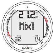
Fig. 6.19 Changing gas mix. Current gas mix is MIX1 (32%). Scroll though enabled mixes by pressing UP or DOWN button. Select new mix by pressing SELECT button.
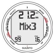
Fig. 6.20 Changing gas mix. Maximum Operating Depth exceeded, gas can not be selected. PO2 value is blinking.
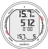
Fig. 6.21. Diving in Gauge mode. Current dive time is 5 minutes 12 seconds.
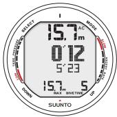
Fig. 6.22. Dove Timer has been reset. Last leg was 5min 23s. You are 12s into current leg.
The D9 has as a special feature the possibility to set two additional nitrox mixes to be used during the dive. This feature can be activated by setting the MIX2 and/or MIX3 "ON" and entering other parameters in the same way as on the primary gas. Mix 2 and 3 settings are held until you change them (they will not return to default settings automatically). Cylinder pressure data is available for one wireless transmitter only. A dive is always started with MIX1, during the dive the D9 lets you change to any enabled mix, which is within the set maximum oxygen partial pressure. Tissue calculation during dive is based on the mix you have selected.
The D9 allows gas change to enabled gas mixes during the dive. Gas change is made by the following procedure:
- Press the UP button until the D9 starts to show "MIX 1in the middle display (Fig. 6.19).
- Scroll between enabled mixes with UP and DOWN buttons
- Mix number, 02% and PO2 for the mixes are shown when scrolling. If set PO2 limit is exceeded it will be shown with the PO2 value blinking. The D9 does not
allow change to a gas which set PO2 is exceeded. In such a case the mix is shown but cannot be selected (Fig. 6.20)
- Select mix by pressing SELECT.
- If no button is pressed in 15 seconds the D9 will go back to dive display without changing gas mix. Upon ascent the D9 prompts you to change gas when the PO2 level you have set for next mix is allowing a gas change. The prompt is an audible three beeps and the current mix 0% starts to blink.
NOTE: The D9 will not let you switch to gases which maximum PO2 levels are exceeded.
6.3. DIVING IN GAUGE MODE [DIVEGAUGE]
If set to Gauge mode, the dive computer can be used as a bottom timer or as an freediving instrument.
In the Gauge mode the total Dive Time is always displayed in minutes in the lower right corner. In addition a Dive Timer in the center window displays time in minutes and seconds (Fig. 6.21). The center window Dive Timer is activated at the start of the dive and it can be reset during the dive and used as a stopwatch by pressing the SELECT button (Fig. 6.22).
![SUUNTO D9 - DIVING IN GAUGE MODE [DIVEGAUGE] - 1](/content/2025/01/149200/images/177ca910be7cdbbe29c07286f8f9287d6a58a0b4aa0ad05aacc09440e13f8c63.jpg)
Fig. 6.23. Activating the compass from dive mode.
![SUUNTO D9 - DIVING IN GAUGE MODE [DIVEGAUGE] - 2](/content/2025/01/149200/images/af8b07522592be52b6a3cd37bbfea891a692574d49bebbca0462d1825c02db8f.jpg)
Fig. 6.24. Surface display. It is 6minutes since you have surfaced from a 32 minute dive, which maximum depth was 18.0m [60 ft]. The present depth is 0.0m [0 ft]. Airplane symbol and No-Fly value indicates that you should not fly for 11hrs 54minutes. Diver Attention Symbol indicates that you should prolong your surface interval time because of excess micro-bubbles.
When the SELECT button is pressed during the dive:
- A special mark, bookmark is written in the profile memory.
- The Dove Timer shown in the center window is stopped, reset and started again
- The previously timed interval (leg) is displayed
Tank pressure (if enabled) and ascent rate indicator are also displayed during the dive.
NOTE! The Gauge mode provides no decompression information.
NOTE! There is no ascent rate monitoring in the Gauge mode
NOTE! If you dive with the Gauge mode, it is not possible to change between the modes before the no fly time has counted down.
6.4. USING THE COMPASS IN DIVE MODE
The compass function can be accessed also from the DIVE mode (Fig. 6.23). To access the compass from either mode hold down the S (Select) button for >2s . The compass display will be as described in chapter 4.2. with the additions that:
- the current depth is displayed
- all diving related alternative display data is available
- the ascent rate bar-graph is displayed
- the tank pressure bar-graph is displayed (if wireless transmission enabled)
In order to save battery power the compass display will automatically return to the DIVE mode after 60s has elapsed since the last button press.
6.5. AT THE SURFACE
6.5.1. SURFACE INTERVAL
An ascent to any depth shallower than 1.2m [4 ft] will cause the DIVING display to be replaced by the SURFACE display, giving the following information (Fig. 6.24.):
present depth in meters [ft]
- no-flying warning indicated by an airplane icon (Table 6.1)
- Diver attention symbol indicates surface interval time should be prolonged (Table 6.1)
STOP label for 5 min, if the Mandatory Safety Stop was violated
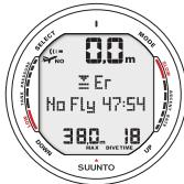
Fig. 6.25. Surface Mode after a violated decompression dive. Er symbol indicates that you have violated the ceiling for more than three minutes. You must not dive again for at least 48 hours.
- Er, if the decompression ceiling was violated (= Error Mode) (Table 6.1) Or in the alternative displays:
maximum depth of last dive in meters [ft]
- dive time of last dive in minutes, shown as DIVE TIME
- the current time, shown as TIME
- the current temperature with ^ C for Centigrade [or ^ F for Fahrenheit]
- Cylinder pressure in bars [psi] (if enabled)
If set to Nitrox mode, the following information will also be shown:
- the oxygen percentage labeled O_2%
- the oxygen partial pressure labeled PO2
- the current oxygen toxicity exposure labeled OLF
6.5.2. DIVE NUMBERING
Several repetitive dives are considered to belong to the same repetitive dive series when the dive computer has not counted the no-flying time to zero. Within each series, the dives are given individual numbers. The first dive of the series will be numbered as DIVE 1, the second as DIVE 2, the third as DIVE 3, etc.
If you start a new dive with less than 5 minutes of surface interval time, the dive computer interprets this as a continuation of the previous dive and the dives are considered to be the same. The diving display will return, the dive number will remain un
changed, and the dive time will begin where it left off. After 5 minutes on the surface, subsequent dives are, by definition, repetitive. The dive counter displayed in the Planning Mode will increment to the next higher number if another dive is made.
TABLE 6.1. WARNING SYMBOLS
| Symbol on display | Indication |
| Δ | Diver Attention Symbol |
| Er | Violated Decompression Ceiling |
| NO | Do Not Fly Symbol |
6.5.3. REPETITIVE DIVE PLANNING
The Suunto D9 includes a dive planner that allows you to review the no-decompression limits on a subsequent dive taking the residual nitrogen loading of previous dives in consideration. The Dive Planning mode is explained in chapter 7.1.
6.5.4. FLYING AFTER DIVING
The no-flying time is shown in the center window next to the airplane image. Flying or travelling to a higher altitude should be avoided at any time the computer counts down the no-flying time.
The no-flying time is always at least 12 hours or equivalent to the so-called desaturation time (if longer than 12 hours). For desaturation times lower than 1h 10min no no-fly time is given.
In the permanent Error mode and Gauge mode the no-flying time is 48 hours.
Divers Alert Network (DAN) recommends the following on no-flying times:
- A minimum surface interval of 12 hours would be required in order to be reasonably assured a diver will remain symptom free upon ascent to altitude in a commercial jetliner (altitude up to 2400 m 8000ft ).
- Divers who plan to make daily, multiple dives for several days, or make dives that require decompression stops, should take special precautions and wait for an extended interval beyond 12 hours before flight. Further, the Undersea and Hyperbaric Medical Society (UHMS) suggests divers using standard air cylinders and exhibiting no symptoms of decompression illness wait 24 hours after their last dive to fly in an aircraft with cabin pressure up to 2400m [8000 ft]. The only two exceptions to this recommendation are:
-
If a diver had less than 2 hours total accumulated dive time in the last 48 hours, then a 12 hour surface interval before flying is recommended.
-
Following any dive that required a decompression stop, flying should be delayed for at least 24 hours, and if possible, for 48 hours.
- Suunto recommends that flying is avoided until all the DAN and UHMS guidelines and the dive computer wait to fly conditions are satisfied.
6.6. AUDIBLE AND VISUAL ALARMS
The dive computer features audible and visual alarms to advise when important limits are approached or to acknowledge preset alarms.
A short single beep occurs, when:
- the dive computer is activated.
- when the dive computer automatically returns to the TIME mode.
Three beeps with a three second interval occur, when:
- the cylinder pressure reaches 50 bar [725 psi]. The cylinder pressure display will start to blink (Fig. 6.5).
- the cylinder pressure reaches the selected alarm pressure.
- the calculated remaining air time reaches zero.
Three beeps with a three second interval and activated backlight, when:
- the no-decompression dive turns into a decompression stop dive. An arrow pointing upwards and the blinking ascent warning ASC TIME will appear (Fig 6.10.).
Continuous beeps and activated backlight when:
- the maximum allowed ascent rate, 10m / min [33 ft/min], is exceeded. Ascent rate bar graph blinks and STOP warning appears (Fig. 6.6.).
- the decompression ceiling depth is exceeded. An error warning Er and a downward pointing arrow appear. You should immediately descend to, or below, the ceiling. The instrument will otherwise enter a permanent Error Mode within three minutes, indicated by a permanent Er (Fig. 6.13.).
You are able to preset alarms before the actual dive. The user programmable alarms can be set for maximum depth, dive time and time. The alarms activate when:
-
The preset maximum depth is reached
-
continuous beep series for 24 seconds
-
the maximum depth blinks as long as the present depth value exceeds the adjusted value.
-
The preset dive time is reached
-
continuous beep series for 24 seconds or until any button is pressed.
-
the dive time blinks for one minute
-
The preset alarm time is reached
-
the current time is shown.
- continuous beep series for 24 seconds or until any button is pressed.
- the current time blinks for one minute
OXYGEN ALARMS IN NITROX MODE
Continuous beeps for 3 minutes activated backlight, when:
- the set oxygen partial pressure limit is exceeded. The alternative display is replaced with a current blinking PO_2 value. You should immediately ascend above the PO_2 depth limit (Fig. 6.17-6.18.).
- the OLF value reaches 80% . The OLF value will start to blink.
- the OLF value reaches 100% . The OLF value will blink.
NOTE! When the backlight is turned OFF, it does not illuminate when an alarm is activated.
WARNING!
WHEN THE OXYGEN LIMIT FRACTION INDICATES THAT THE MAXIMUM LIMIT IS REACHED, YOU MUST IMMEDIATELY ASCEND UNTIL THE WARNING STOPS BLINKING! Failure to take action to reduce oxygen exposure after the warning is given can rapidly increase the risk of oxygen toxicity and the risk of injury or death.
6.7. ERROR CONDITIONS
The dive computer has warning indicators that alert the user to react to certain situations that would significantly increase the risk of DCI. If you do not respond to its warnings, the dive computer will enter an Error Mode, indicating that the risk of DCI has greatly increased. If you understand and operate the dive computer sensibly, it is very unlikely you will ever put the instrument into the Error Mode.
OMITTED DECOMPRESSION
The Error Mode results from omitted decompression, i.e. when you stay above the ceiling for more than three minutes. During this three-minute period the Er warning is shown and the audible alarm beeps. After this, the dive computer will enter a permanent Error Mode. The instrument will continue to function normally if you descend below the ceiling within this three-minute period.
Once in the permanent Error Mode only the ER warning is shown in the center window. The dive computer will not show times for ascent or stops. However, all the other displays will function as before to provide information for ascent. You should immediately ascend to a depth of 3 to 6m [10 to 20 ft] and remain at this depth until air supply limitations require you to surface.
After surfacing, you should not dive for a minimum of 48 hours. During the permanent Error Mode, the Er text will be displayed in the center window and the Planning Mode will be disabled.
7. MEMORY MODE
The memory options include a dive planner (MEMplan), dive logbook (MEMlog) and diving history (MEMhis) (fig 7.1)
The dive entry time and date is registered in the Logbook memory. Always check before diving that the time and date are correctly set, especially after traveling between different time zones.
The memory modes are accessing by pressing the MODE button until the default MEM mode is displayed. The MEM submode can be changed by pressing UP/DOWN buttons.
7.1. DIVE PLANNING MODE [MEMplan]
The Dove planning mode displays no-decompression times for a new dive taking into account the effects of previous dives.
When entering the MEMplan mode the display will first briefly show the remaining desaturation time (Fig 7.2) before going into plan mode (Fig 7.3).
By pressing the UP/DOWN buttons you can scroll the nodecompression limits in 3 m [10 ft] increments ending at 45 m [150 ft]. No-decompression limits longer than 99min are displayed as “—”.
![SUUNTO D9 - DIVE PLANNING MODE [MEMplan] - 1](/content/2025/01/149200/images/f65504ee12649b3989cc5895ab3a5f95a355e70d9ed1f791bbe80b482284e82d.jpg)
Fig. 7.1. Memory options. [MEM].
a) Planning mode
![SUUNTO D9 - DIVE PLANNING MODE [MEMplan] - 2](/content/2025/01/149200/images/baef53c6f10ec8bac99c58d1caecdda4906522bce58e3c0b678cf9276e5b4012.jpg)
b) Logbook mode
![SUUNTO D9 - DIVE PLANNING MODE [MEMplan] - 3](/content/2025/01/149200/images/cbeb0b1617373f9dc3986ccbe2d50987d313f04ed2c187a0ad53d047b225ddbe.jpg)
c) History mode
![SUUNTO D9 - DIVE PLANNING MODE [MEMplan] - 4](/content/2025/01/149200/images/2f2a099bdf5b1796c5797351660c059d8882b63bd157c9bbe95373ca06244613.jpg)
Fig. 7.2. Entering Dove Planning Mode. Desaturation time is displayed
![SUUNTO D9 - DIVE PLANNING MODE [MEMplan] - 5](/content/2025/01/149200/images/8a6d628026a6dd448d4c55f77737109f7206af075cfd27725a36c33de2cf4f5a.jpg)
Fig. 7.3. Dove Planning Mode. For a 9m dive the available no-decompression time is 67 minutes.
The Planning mode accounts for the following information from previous dives:
- any calculated residual nitrogen
all dive history for the past four days
The no-decompression times given for different depths will therefore be shorter than before your first "fresh" dive.
You can exit the planning mode by pressing the MODE button.
NOTE! The Planning mode is disabled in Gauge mode and in Error mode (see section 6.7. "Error Conditions"). The planning mode calculates no dec times for MIX1 only. If additional mixes are enabled in the Nitrox mode they do not affect the calculations in PLAN mode.
Higher Altitude and conservative Personal Adjustment Modes will shorten the no-decompression time limits. These limits at different Altitude and Personal Adjustment Mode selections are shown in Table 10.1 and 10.2 in section 10.2. "Suunto Reduced Gradient Bubble Model".
DIVE NUMBERING SHOWN DURING DIVE PLANNING
Dives belong to the same repetitive dive series if the instrument was still counting down the no-fly time at the beginning of the dive.
The surface interval must be at least 5 minutes for a dive to be considered a repetitive dive. Otherwise, it is considered a continuation of the same dive. The dive number will not change and the dive time will continue where it left off (see also section 6.5.2. "Dive Numbering").
7.2. DIVE LOGBOOK [MEMlog]
This instrument has a very sophisticated high capacity Logbook and Profile Memory. The data is recorded to the profile memory based on the selected sampling rate. Dives shorter than the recording interval are not registered (see chapter 5.2.5 Setting Sample Rate).
For each dive there are three pages of logbook dive information. Use the SELECT button to scroll the display between Logbook pages I, II, and III. The data of the most recent dive is shown first.
The END OF LOGS text is displayed between the oldest and most recent dive. (Fig. 7.7.)
![SUUNTO D9 - DIVE LOGBOOK [MEMlog] - 1](/content/2025/01/149200/images/863d870562b70e297a5586c7e0dbf45eb3d78af6e741d7ead01bc6cb2c45643c.jpg)
Fig. 7.4 Logbook, page I. Scroll different pages of specific dive.
![SUUNTO D9 - DIVE LOGBOOK [MEMlog] - 2](/content/2025/01/149200/images/e72a6aaaeee0a530f16bb5c0f16fe8ce9389e9005f125e1b7d36f88caf58cde7.jpg)
Fig. 7.5. Logbook, page II. Main dive related data.
![SUUNTO D9 - DIVE LOGBOOK [MEMlog] - 3](/content/2025/01/149200/images/3103218ec6b11e3f5c1d841282aa49d4545d7c10e08fa30ad6ea9cc547f943ba.jpg)
Fig. 7.6. Logbook, page III. Dive profile. Press Up to scroll.
![SUUNTO D9 - DIVE LOGBOOK [MEMlog] - 4](/content/2025/01/149200/images/8cf353f2592354959d03bc571945f3682e88f2168ee849d2ad2582cb18e4a6d8.jpg)
Fig. 7.7. Logbook, end of the memory.
The following information will be shown on three pages:
Page I. main display (Fig. 7.4.)
maximum depth (NOTE! Depending on the sampling rate, the reading may differ from the maximum depth reading of the Dove History up to 0.3 m [1 ft].)
- date of dive
type of dive (Air, EAN, Gauge)
- dive start time
- dive number
- oxygen percentage for mix1
- total dive time
Page II (Fig. 7.5.)
maximum depth
surface time before previous dive
- warnings
- used tank pressure (if enabled)
Page III (Fig. 7.6.)
depth/time profile of the dive
real time water temperature
real time tank pressure (if enabled)
The memory will retain approximately the last 36 hours of dive time. After that, when new dives are added, the oldest dives are deleted. The contents of the memory will remain when the battery is changed (assuming that the replacement has been done according to the instructions).
NOTE! Several repetitive dives are considered to belong to the same repetitive dive series if the no-flying time has not ended. See "Dive Numbering" in section 6.5.2. for further information.
The Dive History is a summary of all the dives recorded by the dive computer. The following information will be shown on the display (Fig. 7.8):
the maximum depth ever reached
the total accumulated dive time in hours
the total number of dives.
The Dove History Memory can hold a maximum of 999 dives and 999 diving hours. When these maximum values are reached, the counters will start again from zero.
NOTE! The maximum depth can be reset to 0.0m [0 ft] using the PC-Interface unit and the Suunto Dive Manager software.
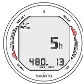
Fig. 7.8. Dive History information. Total number of dives, dive hours and maximum depth.
8. ADDITIONAL FEATURES
The instrument can be connected to an IBM compatible personal computer (PC), using the PC-Interface and software. With the PC-Interface unit, dive data from the dive computer can be downloaded to a PC. The PC software can be used for educational and demonstration purposes, for planning dives, and for keeping a complete record of your dive history with the instrument. Additional Logbook data can also be added. Paper copies of your dive log and profiles can easily be printed.
The data transfer is carried out using the connector on right side of the unit. The following data is transferred to the PC:
depth profile of the dive
- dive time
- preceding surface interval time
- dive number
- dive start time (year, month, day and time)
- dive computer settings
- oxygen percentage settings and maximum OLF (in Nitrox mode)
- tissue calculation data
real time water temperature
- additional dive information (e.g. SLOW and Mandatory Safety Stop violations, Diver Attention Symbol, Bookmark, Surfaced Mark, Decompression Stop Mark, Ceiling Error Mark,gas change)
- dive computer serial number
personal 30 character information - real time tank pressure consumption (with optional wireless transmitter in use)
surface air consumption.
Using the PC software, you are able to enter setup options such as:
input a personal, 30 character field into the D9 (i.e. your name)
reset the Dove History's max depth to zero
It is also possible to manually add comments, multimedia and other personal information to the PC based dive data files.
8.1. SUUNTO DIVE MANAGER
SYSTEM REQUIREMENTS
Minimum CPU speed 500 Mhz
64 MB of RAM (recommended 128 MB)
40 MB of available hard-disk space
Microsoft Windows 98/2000/ME/XP
Minimum resolution: 800 × 600 (recommended 1024 × 768 )
USB port
INSTALLATION
To install Suunto Dove Manager:
- Insert the Suunto Dive Manager CD-ROM into the drive.
- Wait for the installation to begin and follow the installation instructions.
NOTE: If the installation does not start automatically, click Start -> Run and type D:\setup.exe.
8.2.SUUNTOSPORTS.COM
SuuntoSports.com is an international free web community where you can refine and share the data that you have measured with your personal Suunto instrument and analyzed with the sport-specific PC interface. SuuntoSports.com offers you a number of features that help you to get the most out of your sport and your Suunto D9.
If you already own a personal Suunto sports instrument you can access all sport-specific functions through registration. If you do not yet have an instrument you may either log in as a guest or register yourself. As a guest you can view and read, but registration gives you the right to use other functions and participate to discussions.
SYSTEM REQUIREMENTS
SuuntoSports.com has the following system requirements:
-
Internet Connection
Modem: recommended 56k or faster -
Browser: IE 4.0 or better, Netscape 4.7x or newer
Resolution: minimum 800 × 600 , best viewed with 1024 × 768
SUUNTOSPORTS.COM SECTIONS
SuuntoSports.com includes three sections with several functions. The following paragraphs describe only the basic functions of SuuntoSports.com. You can find detailed descriptions of all the site functions and activities and step-by-step instructions for using them from the site Help. The Help is available on each page and its icon is located on the right side of the bar dividing the screen. The Help is frequently updated as the site develops.
SuuntoSports.com offers several possibilities for searching the information on site. In addition to the free search, you can search, for example, for groups, users, resorts, logs and sports.
The information published on the SuuntoSports.com contains internal links so that you do not always have to search for the information from the very beginning. For example, if you view a description of a resort, you can follow the links and view the resort information sender's personal information, logs related to the resort and charts created from the logs, if the sender has agreed to this information being made public.
My Suunto
The My Suunto section of the site is meant for your personal information. You can store information about yourself, your wristop computer, your sporting and training activities, etc. When you upload your personal logs to SuuntoSports.com they are displayed
in your personal information. Here you can also manage them and decide if they can be presented to all other community users or just to limited groups.
When you have uploaded logs to SuuntoSports.com, you can create charts from the dive related data in the logs. You can also publish your logs and compare them with other users' logs.
The My Suunto section also contains a personal calendar that you can use to mark personal events and other useful information.
Communities
In the Communities section, SuuntoSports.com users can form or search groups and manage their own groups. For example, you can create a group for all your diving friends, and share information about each other's trips, give advice and discuss where and when you could go diving together. Groups can be either open or closed—closed groups mean that you have to apply for a membership and be accepted, before you can participate in group activities.
All groups have a home page that displays information about group events and includes news, noticeboard and other information. Group members can also use group-specific bulletin boards, chat rooms and group calendars, and add links and create group activities.
Sport Forums
SuuntoSports.com has its own forum for each Suunto sport. The basic features and functions are the same for all sport forums—sport-specific news, bulletin boards and
chat rooms. Users can also suggest links to sports-related sites and tips regarding the sport and equipment to be published on the site, or publish their own travel reports.
Sport forums include presentations of the resorts that are related to the sport. Users can rank the resorts with comments and the results are published next to the resort information. A ranking list can also be created for other things—for example, where are the best diving sites, what group has most members, who has uploaded most logs, and so on.
GETTING STARTED
To join the SuuntoSports.com community, connect to the Internet, open your web browser and go to www.suuntosports.com. When the opening page appears, click the Register icon and register yourself and your Suunto sports instrument. You can change and update your personal and equipment profiles in My Suunto section afterwards.
After the registration you will automatically enter the SuuntoSports.com home page that introduces the site structure and functional principles.
Note!
SuuntoSports.com is continuously developed further and its content is subject to change.
9. CARE AND MAINTENANCE
This SUUNTO D9 dive computer is a sophisticated precision instrument. Though designed to withstand the rigors of scuba diving you must treat it with proper care and caution as any other precision instrument.
9.1. IMPORTANT INFORMATION
WATER CONTACTS AND PUSH BUTTONS
Contamination or dirt on the water contacts/connector or push buttons may prevent the automatic activation of the Dive Mode and cause problems during the data transfer. Therefore, it is important that the water contacts and push buttons are kept clean. If the water contacts of the instrument are active (AC-text remains on display) or the Dive Mode activates on its own, the reason for this is probably contamination or invisible marine growth that may create an unwanted electric current between the contacts. It is important that the dive computer is carefully washed in fresh water after the day's diving is completed. The contacts can be cleaned with fresh water and, if necessary, a mild detergent and a soft brush.
9.2. CARE OF YOUR DIVE COMPUTER
- NEVER try to open the case of the dive computer.
Service your dive computer every two years or after 200 dives (whichever comes first) by an authorized dealer or distributor. This service will include a general operational check, replacement of the battery, and water resistance
check. The service requires special tools and training. Therefore, it is advisable to contact an authorized SUUNTO dealer or distributor for biennial service. Do not attempt to do any service that you are not sure about how to do.
- Should moisture appear inside the case or battery compartment have the instrument checked immediately by your SUUNTO dealer or distributor.
- Should you detect scratches, cracks or other such flaws on the display that may impair its durability, have it replaced immediately by your SUUNTO dealer or distributor.
- Check strap and the buckle for flaws. If needed, have them replaced by your SUUNTO dealer or distributor.
- Wash and rinse the unit in fresh water after every use.
- Protect the unit from shock, extreme heat, direct sunlight, and chemical attack. The dive computer cannot withstand the impact of heavy objects like scuba cylinders, nor chemicals like gasoline, cleaning solvents, aerosol sprays, adhesive agents, paint, acetone, alcohol etc. Chemical reactions with such agents will damage seals, case and finish.
- Store your dive computer in a dry place when you are not using it.
- The dive computer will display a battery symbol as a warning when the power gets too low. When this happens, the instrument should not be used until the battery has been replaced (see also section 5.1. "Activation and Prechecks").
- Do not fasten the strap of your dive computer too tightly. You should be able to insert your finger between the strap and your wrist.
9.3. MAINTENANCE
If left without care for an extended period, a thin film (often invisible to the eye) will cover the unit. Much like the buildup on the glass of an aquarium, this film is the result of organic contaminants found in both salt and fresh water. Suntan oil, silicone spray and grease will speed up this process. As a result of this buildup, moisture will be trapped next to the water contact and will not allow your Suunto D9 to operate properly.
The water contact can be cleaned with a small brush (e.g. toothbrush).
IMPORTANT: The Suunto D9 should be soaked, then thoroughly rinsed with fresh water and then dried with a soft towel after each dive. Make sure that all salt crystals and sand particles have been flushed out. Check the mineral crystal for possible moisture or water. DO NOT use the D9 if you detect any moisture or water inside.
CAUTION!
- Do not use compressed air to blow water off the unit.
- Do not use solvents or other cleaning fluids that might cause damage.
- Do not test or use the dive computer in pressurized air.
9.4. WATER RESISTANCE INSPECTION
Water resistance of the unit must be checked after replacement of the battery or after other service operations. The check requires special equipment and training.
You must frequently check the display for any sign of leaks. If you find moisture inside your dive computer, there is a leak. A leak must be corrected without delay, as mois-
ture will seriously damage the unit, even beyond repair. SUUNTO does not take any responsibility for damage caused by moisture in the dive computer, if the instructions of this manual are not carefully followed.
In case of a leak, immediately take the dive computer to an authorized SUUNTO dealer or distributor.
9.5. BATTERY REPLACEMENT
9.5.1. COMPUTER BATTERY REPLACEMENT
NOTE! It is advisable to contact an authorized Suunto dealer for battery replacement. It is imperative that the change is made in a proper manner to avoid any leakage of water into the battery compartment or computer.
CAUTION! Defects caused by improper battery installation are not covered by the warranty.
CAUTION! When the battery is changed all nitrogen and oxygen uptake data is lost. Therefore, the no-flying time shown by the computer should have reached zero or you must wait for 48 hours or preferably even 100 hours between dives before you may dive again.
All history and profile data, as well as the altitude, personal and alarm settings, will remain in the dive computer memory after the battery change. However, the clock time and time alarm setting is lost. In the NITROX Mode the Nitrox settings are also reverted back to default settings (MIX1 21% O_2 , 1.4 bar PO_2 , MIX2/MIX3 off).
9.5.2. WIRELESS TRANSMITTER BATTERY REPLACEMENT
NOTE! It is advisable to contact an authorized Suunto dealer for transmitter battery replacement. It is imperative that the change is made in a proper manner to avoid any leakage of water into the transmitter.
CAUTION! Defects caused by improper battery installation are not covered by the warranty.
BATTERY KIT
The transmitter battery kit includes a 3.0 V CR 1/2 AA lithium cell battery and a lubricated O-ring. When handling the battery do not make contact with both of the poles at the same time. Do not touch the metal surfaces of the battery with your bare fingers.
TOOLS REQUIRED
A Phillips head screwdriver
- Soft cloth for cleaning.
TRANSMITTER BATTERY REPLACEMENT
To change the transmitter battery, follow the procedure below:
- Remove the transmitter from the regulator HP port
- Unscrew and remove the four Phillips screws on the back of the transmitter
- Pull off the transmitter cover
-
Carefully remove the o-ring. Be careful not to damage the sealing surfaces.
-
Carefully remove the battery. Do not touch the electrical contacts or the circuit board
Check for any traces of flooding, or for any other damage. In case of a leak or any other damage, bring the transmitter to an authorized SUUNTO dealer or distributor for check and repair.
- Check the condition of the O-ring; a defective O-ring may indicate sealing or other problems. Dispose the old O-ring, even if it seems to be in good condition.
- Check that the o-ring groove and the sealing surface of the cover the are clean. Clean with soft cloth if necessary.
- Gently insert the new battery in the battery compartment. Check the polarity of the battery: the "+" mark should point toward the top of the compartment and the "-" mark towards the bottom.
NOTE! It is imperative to wait at least 30 seconds before re-installing the transmitter battery.
When the battery is re-installed the transmitter sends an overpressure ("---") signal on code 12 for 10 seconds, after which it goes to normal operation, and shuts down after 5min.
-
Check that the new lubricated O-ring is in good condition. Put it in the right position in the o-ring groove. Be very careful not to get any dirt on the o-ring or its sealing surfaces.
-
Carefully put the transmitter cover into place. Note that the cover will only fit in one position. Match the three slots on the inside of the cover with the three ledges below the battery.
- Screw the four screws back into place.
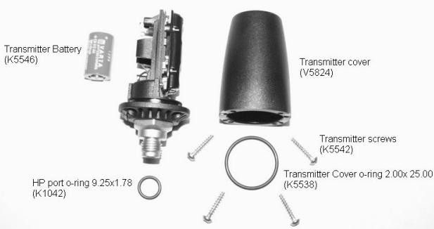
Fig. 9.1 Wireless transmitter parts. The code stands for spare part order number.
10. TECHNICAL DATA
10.1. TECHNICAL SPECIFICATION
Dimensions and weight:
D9:
- Diameter: 50.0 mm 1.97in .
Thickness: 17.6 mm [0.67 in].
Weight: 110g [3.88 oz].
Transmitter:
Max.diameter:40mm[1.57in].
Length: 80mm [3.15 in].
Weight: 118g [4.16 oz].
- Rated working pressure: 300 bar [4000 psi], maximum allowed pressure 360 bar [5000 psi].
Display resolution: 1 bar [1 psi].
Depth Gauge:
- Temperature compensated pressure sensor.
Salt water calibrated, in fresh water the readings are about 3% smaller (calibrated complying with EN 13319).
Maximum depth of operation: 100 m [328 ft] (complying with EN 13319).
Accuracy: ± 1% of full scale or better from 0 to 80m [262 ft] at 20^ [68°F] (complying with EN 13319).
- Depth display range: 0 ... 200 m [656 ft].
- Resolution: 0.1 m from 0 to 100 m [1 ft from 0 to 328 ft].
Temperature display:
- Resolution: 1^ [1.5°F].
Display range: -20 ... +50°C [-9 ... +122°F].
Accuracy: ± 2^ [± 3.6^ ] within 20 minutes of temperature change.
Calendar Clock:
Accuracy: ± 25 s/month (at 20^ [68°F]).
12/24 h display.
Other displays:
- Dive time: 0 to 999 min, counting starts and stops at 1.2m [4 ft] depth.
Surface time: 0 to 99 h 59 min. - Dive counter: 0 to 99 for repetitive dives.
- No-decompression time: 0 to 99 min (- - after 99).
- Ascent time: 0 to 99 min (- - after 99).
Ceiling depths: 3.0 to 100m [10 to 328 ft].
Air time: 0 to 99 min (- - after 99).
Displays only in Nitrox mode:
Oxygen%: 21 - 99.
- Oxygen partial pressure display: 0.5 - 1.6 bar depending on the limit setting.
Oxygen Limit Fraction: 1 - 200% with 1% resolution
Logbook/Dive Profile Memory:
Recording interval: 20 seconds adjustable (1-10-20-30-60s), records the maximum depth, minimum temperature and minimum tank pressure of each interval.
- Memory capacity: approximately 36 hours of diving with 20 seconds recording interval.
- Depth accuracy: 0.3 m [1 ft].
Operating Conditions
Normal altitude range: 0 to 3000 m [10000 ft] above sea level.
- Operating temperature: 0^ to 40^ [32°F to 104°F].
- Storage temperature: -20^ to +50^ [-4^ to +122^] .
It is recommended that the instrument be stored in a dry place at room temperature.
NOTE! Do not leave the dive computer in direct sunlight!
Tissue Calculation Model
- Suunto Deepstop RGBM algorithm (developed by SUUNTO and Bruce R. Wienke, BS, MS and PhD).
- 9 tissue compartments.
-
Tissue compartment halftimes: 2.5, 5, 10, 20, 40, 80, 120, 240 and 480 minutes (on gassing). The off gassing halftimes are slowed down.
-
Reduced gradient (variable) "M" values based on diving habit and dive violations. The "M" values are tracked up to 100 hours after a dive.
- The EAN and oxygen exposure calculations are based on recommendations by R.W. Hamilton, PhD and currently accepted exposure time limit tables and principles.
Battery
D9:
One 3 V lithium battery: CR 2450
- Battery storage time (shelf life): Up to three years.
- Replacement: Every two years or more often depending on dive activity.
- Life expectancy at 20^ [68°F]:
- 0 dives/y -> 2 years
- 100 dives/y -> 1,5 years
- 300 dives/y ->1 year
The following conditions have an affect on the expected battery lifetime:
The length of the dives.
- The condition in which the unit is operated and stored (e.g. temperature/cold conditions). Below 10^ [50°F] the expected battery lifetime is about 50-75% of that at 20^ [68°F].
The use of the backlight and audible alarms.
Use of the compass
- The quality of the battery (some lithium batteries may exhaust unexpectedly,
which cannot be tested in advance).
- The time the dive computer has been stored until it gets to the customer. The battery is installed into the unit at the factory.
Transmitter:
- One 3V lithium battery: 1/2AA (K5546) and O-ring 2,00 mm x 25,00 mm (K5538).
- Battery storage time (shelf life): Up to three years.
- Replacement: Every two years or more often depending on dive activity.
- Life expectancy at 20^ [68°F]:
- 0 dives/y ->3 years
- 100 dives/y ->2 years
- 400 dives/y -> 1 year
The following conditions have an affect on the expected battery lifetime:
The length of the dives.
- The condition in which the unit is operated and stored (e.g. temperature/cold conditions). Below 10^ [50°F] the expected battery lifetime is about 50-75% of that at 20^ [68°F].
- The use of the backlight and audible alarms.
- The quality of the battery (some lithium batteries may exhaust unexpectedly, which cannot be tested in advance).
- The time the dive computer has been stored until it gets to the customer. The battery is installed into the unit at the factory.
NOTE! Low temperature or an internal oxidation of the battery may cause the battery warning even though the battery has enough capacity. In this case, the warning usually disappears when the Dive Mode is activated again.
10.2. SUUNTO REDUCED GRADIENT BUBBLE MODEL (RGBM)
The Suunto Reduced Gradient Bubble Model (RGBM) is a modern algorithm for predicting both dissolved and free gas in the tissues and blood of divers. It was developed in a co-operation between Suunto and Bruce R. Wienke BSc, MSc. PhD. It is based on both laboratory experiments and diving data, including data from DAN.
It is a significant advance on the classical Haldane models, which do not predict free gas (microbubbles). The advantage of Suunto RGBM is additional safety through its ability to adapt to a wide variety of situations. Suunto RGBM addresses a number of diving circumstances outside the range of just dissolved gas models by:
Monitoring continuous multiday diving
- Computing closely spaced repetitive diving
- Reacting to a dive deeper than the previous dive
- Adapting for rapid ascents which produce high micro-bubble (silent-bubble) build-up
- Incorporating consistency with real physical laws for gas kinetics.
Suunto RGBM Adaptive decompression
The SUUNTO RGBM algorithm adapts its predictions of both the effects of microbubble build-up and adverse dive profiles in the current dive series. It will also change
these calculations according to the personal adjustment you select.
The pattern and speed of decompression at the surface is adjusted according to micro-bubble influence.
Also on repetitive dives adjustment may be applied to the maximum allowable nitrogen overpressure in each theoretical tissue group.
Depending on circumstances Suunto RGBM will adapt the decompression obligations by doing any or all of the following:
- Reducing no-decompression stop dive times
- Adding Mandatory Safety Stops
- Increasing decompression stop times
- Advising an extended surface interval (Diver Attention symbol).
Diver Attention Symbol - Advice to Extend Surface Interval.
Some patterns of diving cumulatively add a higher risk of DCI, e.g. dives with short surface intervals, repetitive dives deeper than earlier ones, multiple ascents, substantial multiday diving. When this is detected in addition to adapting the decompression algorithm the Suunto RGBM model will in some circumstances also advise, with the Diver Attention Symbol (review chapter 5.2) that the diver extend the surface interval.
NO-DECOMPRESSION LIMITS
The no-decompression limits displayed by the dive computer for the first dive to a single depth (see Table 10.1. and Table 10.2.), are slightly more conservative than those permitted by the U.S. Navy tables.
TABLE 10.1. NO-DECOMPRESSION TIME LIMITS (MIN) FOR VARIOUS DEPTHS (M) FOR THE FIRST DIVE OF A SERIES
| Depth [m] | Personal Mode / Altitude Mode | ||||||||
| P0/A0 | P0/A1 | P0/A2 | P1/A0 | P1/A1 | P1/A2 | P2/A0 | P2/A1 | P2/A2 | |
| 9 | -- | 163 | 130 | 163 | 130 | 96 | 130 | 96 | 75 |
| 12 | 124 | 89 | 67 | 89 | 67 | 54 | 67 | 54 | 45 |
| 15 | 72 | 57 | 43 | 57 | 43 | 35 | 43 | 35 | 29 |
| 18 | 52 | 39 | 30 | 39 | 30 | 25 | 30 | 25 | 21 |
| 21 | 37 | 29 | 23 | 29 | 23 | 20 | 23 | 20 | 15 |
| 24 | 29 | 24 | 19 | 24 | 19 | 16 | 19 | 16 | 12 |
| 27 | 23 | 18 | 15 | 18 | 15 | 12 | 15 | 12 | 9 |
| 30 | 18 | 14 | 12 | 14 | 12 | 9 | 12 | 9 | 7 |
| 33 | 13 | 11 | 9 | 11 | 9 | 8 | 9 | 8 | 6 |
| 36 | 11 | 9 | 8 | 9 | 8 | 6 | 8 | 6 | 5 |
| 39 | 9 | 8 | 6 | 7 | 6 | 5 | 6 | 5 | 4 |
| 42 | 7 | 6 | 5 | 6 | 5 | 4 | 5 | 4 | 4 |
| 45 | 6 | 5 | 5 | 5 | 5 | 4 | 5 | 4 | 3 |
TABLE 10.2. NO-DECOMPRESSION TIME LIMITS (MIN) FOR VARIOUS DEPTHS [FT] FOR THE FIRST DIVE OF A SERIES
| Depth [ft] | Personal Mode / Altitude Mode | ||||||||
| P0/A0 | P0/A1 | P0/A2 | P1/A0 | P1/A1 | P1/A2 | P2/A0 | P2/A1 | P2/A2 | |
| 30 | -- | 160 | 127 | 160 | 127 | 92 | 127 | 92 | 73 |
| 40 | 120 | 86 | 65 | 86 | 65 | 52 | 65 | 52 | 43 |
| 50 | 69 | 56 | 41 | 56 | 41 | 34 | 41 | 34 | 28 |
| 60 | 50 | 38 | 29 | 38 | 29 | 25 | 29 | 25 | 20 |
| 70 | 36 | 29 | 22 | 29 | 22 | 20 | 22 | 20 | 15 |
| 80 | 28 | 23 | 19 | 23 | 19 | 15 | 19 | 15 | 11 |
| 90 | 22 | 18 | 15 | 18 | 15 | 11 | 15 | 11 | 9 |
| 100 | 17 | 14 | 11 | 14 | 11 | 9 | 11 | 9 | 7 |
| 110 | 13 | 11 | 9 | 11 | 9 | 7 | 9 | 7 | 6 |
| 120 | 10 | 9 | 8 | 9 | 8 | 6 | 8 | 6 | 5 |
| 130 | 9 | 7 | 6 | 7 | 6 | 5 | 6 | 5 | 4 |
| 140 | 7 | 6 | 5 | 6 | 5 | 4 | 5 | 4 | 4 |
| 150 | 6 | 5 | 4 | 5 | 4 | 4 | 4 | 4 | 3 |
ALTITUDE DIVING
The atmospheric pressure is lower at high altitudes than at sea level. After traveling to a higher altitude, the diver will have additional nitrogen in his body, compared to the equilibrium situation at the original altitude. This "additional" nitrogen is released gradually in time and equilibrium is reached. It is recommended that you acclimate to the new altitude by waiting at least three hours before making a dive.
Before high altitude diving, the instrument must be set to the Altitude Adjustment mode to adjust the calculations for the new altitude. The maximum partial pressures of nitrogen allowed by the mathematical model of the dive computer are reduced according to the lower ambient pressure.
As a result, the allowed no-decompression stop limits are considerably reduced.
SURFACE INTERVALS
The dive computer requires a minimum surface interval of 5 minutes between dives. If a surface interval is shorter than 5 minutes, the next dive is treated as a continuation of the previous dive.
10.3. OXYGEN EXPOSURE
The oxygen exposure calculations are based on currently accepted exposure time limit tables and principles. In addition to this the dive computer uses several methods to conservatively estimate the oxygen exposure. These include for example:
-
the displayed oxygen exposure calculations are upped to the next higher percentage value
-
for recreational scuba diving, the recommended upper limit of 1.4 bar PO_2 is used as a default
- the CNS% limits up to 1.6 bar are based on 1991 NOAA Diving Manual limits
- the OTU monitoring is based on the long-term daily tolerance level and the recovery rate is reduced
Oxygen related information displayed by the dive computer is also designed to ensure all warnings and displays in the appropriate phases of a dive. E.g. the following information will be shown before and during a dive, when the computer is set in Nitrox mode:
- the selected O_2% on the alternative display
- OLF% alternative display for either CNS% or OTU% (whichever larger)
audible alarms are given and the OLF value starts to blink when the 80% and 100% limits are exceeded
audible alarms are given and the actual PO_2 value blinks when it exceeds the preset limit - in dive planning the maximum depth according to the O_2% and maximum PO_2 selected.
11. WARRANTY
NOTE! The warranty arrangements are different in different countries. The dive computer packaging contains information regarding the warranty benefits and requirements applicable to your purchase.
This Suunto dive computer is warranted against defects in workmanship and materials for a period of two years after purchase to the original owner subject to and in accordance with the terms and conditions set forth below:
The dive computer should be serviced or repaired only by an authorized Suunto dealer or distributor.
This warranty does not cover damage to the product resulting from improper usage, improper maintenance, neglect of care, alteration or unauthorized repair. This warranty will automatically become void if proper preventive maintenance procedures have not been followed as outlined in the use and care instructions for this product.
If a claim under this or any other warranty appears to be necessary, return the product, freight prepaid, to your Suunto dealer or distributor or qualified repair facility. Include your name and address, proof of purchase and/or service registration card, as required in your country. The claim will be honored and the product repaired or replaced at no charge and returned in what your Suunto dealer or distributor determines a reasonable amount of time, provided all necessary parts are in stock. All repairs made, not covered under the terms of this warranty, will be made at the owner's expense. This warranty is non-transferable from the original owner.
All implied warranties, including but not limited to the implied warranties of merchantability and fitness for a particular purpose, are limited from date of purchase and in scope to the warranties expressed herein. Suunto shall not be liable for loss of use of the product or other incidental or consequential costs, expenses or damage incurred by the purchase. All warranties not stated herein are expressly disclaimed.
Some states do not allow the exclusion or limitation of implied warranties of consequential damages, so the above exclusions or limitations may not apply to you. This warranty gives you specific legal rights, and you may also have other rights that vary from state to state.
This warranty does not cover any representation or warranty made by dealers or representatives beyond the provisions of this warranty. No dealer or representation is authorized to make any modifications to this warranty or to make any additional warranty.
Battery replacement is not covered by this warranty.
This Instruction Manual should be kept with your dive computer.
12. GLOSSARY
| Air Time | The amount of dive time remaining, based on a calculation of cylinder pressure and ambient pressure and present air consumption. |
| Altitude dive | A dive made at an elevation greater than 300 m [1000 ft] above sea level. |
| Ascent rate | The speed at which the diver ascends toward the surface. |
| ASC RATE | Abbreviation for ascent rate. |
| Ascent time | The minimum amount of time needed to reach the surface on a decompression stop dive. |
| ASC TIME | Abbreviation for ascent time. |
| Ceiling | On a decompression stop dive the shallowest depth to which a diver may ascend based on computer nitrogen load. |
| Ceiling Zone | On a decompression stop dive the zone between the ceiling and the ceiling plus 1.8 m [6 ft]. This depth range is displayed with the two arrows pointing toward each other (the "hour glass" icon). |
| CNS | Abbreviation for Central Nervous System toxicity. |
Central Nervous System Toxicity
Toxicity caused by oxygen. Can cause a variety of neurological symptoms. The most important of which is an epileptic-like convulsion which can cause a diver to drown.
CNS%
Central Nervous System toxicity limit fraction. Also note Oxygen Limit Fraction
Compartment
See "Tissue group".
DAN
Divers Alert Network.
DCI
Abbreviation for decompression illness.
Decompression
Time spent at a decompression stop or range before surfacing, to allow absorbed nitrogen to escape naturally from tissues.
Decompression range
On a decompression stop dive the depth range, between the floor and ceiling, within which a diver must stop for some time during ascent.
Decompression illness
Any of a variety of maladies resulting either directly or indirectly from the formation of nitrogen bubbles in tissues or body fluids, as a result of inadequately controlled decompression. Commonly called "bends" or "DCI".
| Dive series | A group of repetitive dives between which the dive computer indicates some nitrogen loading is present. When nitrogen loading reaches zero the dive computer deactivates. |
| Dive time | Elapsed time between leaving the surface to descend, and returning to the surface at the end of a dive. |
| ΔP | Delta P, describing the Cylinder Pressure drop during the dive; difference in cylinder pressure between beginning and end of dive. |
| EAD | Abbreviation for equivalent air depth. |
| EAN | Abbreviation for enriched air nitrox. |
| Enriched Air Nitrox | Also called Nitrox or Enriched Air = EANx. Air that has some oxygen added. Standard mixes are EAN32 (NOAA Nitrox I = NN I) and EAN36 (NOAA Nitrox II = NN II). |
| Equivalent Air Depth | Nitrogen partial pressure equivalent table. |
| Floor | The deepest depth during a decompression stop dive at which decompression takes place. |
| Half-time | After a change in ambient pressure, the amount of time required for the partial pressure of nitrogen in a theoretical compartment to go half-way from its previous value to saturation at the new ambient pressure. |
HP Abbreviation for high pressure (= cylinder pressure).
Multi-level dive A single or repetitive dive that includes time spent at various depths and whose no-decompression limits are therefore not determined solely by the maximum depth attained.
NITROX In sports diving refers to any mix with a higher fraction of oxygen than standard air.
NOAA United States National Oceanic and Atmospheric Administration.
No-decompression time The maximum amount of time a diver may remain at a particular depth without having to make decompression stops during the subsequent ascent.
No-decompression dive Any dive which permits a direct, uninterrupted ascent to the surface at any time.
NO DEC TIME Abbreviation for no-decompression time limit.
OEA = EAN = EANx Abbreviation for Oxygen Enriched Air Nitrox.
OLF Abbreviation for Oxygen Limit Fraction.
OTU Abbreviation for Oxygen Tolerance Unit.
Oxygen Tolerance Unit Is used to measure the Whole-Body-Toxicity.
Oxygen Limit Fraction A term used by SUUNTO for the values displayed in the
| Oxygen Toxicity bargraph. The value is either the CNS% or the OTU%. | |
| O2% | Oxygen percentage or oxygen fraction in the breathing gas. Standard air has 21% oxygen. |
| Oxygen partial pressure | Limits the maximum depth to which the used Nitrox mixture can safely be used. The maximum partial pressure limit for enriched air diving is 1.4 bar. The contingency partial pressure limit is 1.6 bar. Dives beyond this limit have the risk for immediate oxygen toxicity. |
| PO2 | Abbreviation for oxygen partial pressure. |
| RGBM | Abbreviation for Reduced Gradient Bubble Model. |
| Reduced Gradient Bubble | Model Modern algorithm for tracking both dissolved and free gas in divers. |
| Repetitive dive | Any dive whose decompression time limits are affected by residual nitrogen absorbed during previous dives. |
| Residual nitrogen | The amount of excess nitrogen remaining in a diver after one or more dives. |
| SURF TIME | Abbreviation for surface interval time. |
| Surface interval time | Elapsed time between surfacing from a dive and beginning a descent for the subsequent repetitive dive. |
Tissue group
Whole-Body Toxicity
Theoretical concept used to model bodily tissues for the construction of decompression tables or calculations.
Another form of oxygen toxicity, which is caused by prolonged exposure to high oxygen partial pressures. The most common symptoms are irritation in the lungs, a burning sensation in the chest, coughing and reduction of the vital capacity. Also called Pulmonary Oxygen Toxicity. See also OTU.
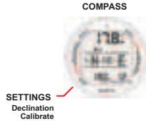
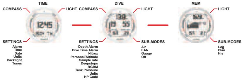
| Model of Computer: | Serial number: |
| Date of purchase | |
| Place of purchase/Store name | |
| Store City | Store Country |
| Store stamp with date of purchase | |
| Name | |
| Address | |
| City | Country |
| Telephone | |
| Signature | |
SUUNTO
TWO YEAR WARRANTY
This product is warranted to be free of defects in material and/or workmanship to the original owner for the above noted period (does not include battery life). Keep a copy of the original purchase receipt and make sure to get this warranty card stamped at the place of purchase. The warranty originates from the date of purchase.
All warranties are limited and are subject to the restrictions given in the instruction manual. This warranty does not cover the damage to the product resulting from improper usage, improper maintenance, neglect of care, alteration, improper battery replacement or unauthorized repair.
www.suunto.com
Made in Finland
- COPYRIGHT, TRADEMARK AND PATENT NOTICE
- CE
- EN 13319
- ISO 9001
- WARNING!
- NOTE!
- TABLE OF CONTENTS
- INTRODUCTION 14
- GETTING ACQUAINTED 19
- TIME MODE 24
- Choice of Operating Modes and Set-up Options
- The Suunto RGBM/Deep Stop Algorithm
- SAFETY PRECAUTIONS
- EMERGENCY ASCENTS
- DIVE COMPUTER LIMITATIONS
- NITROX
- FREEDIVING
- GETTING ACQUAINTED
- DISPLAY AND BUTTONS
- Mode (M) Button
- Select (S) Button
- Up (UP) Button
- Down (DOWN) Button
- 2.2.WATER CONTACTS
- OPERATING MODES
- WIRELESS PRESSURE TRANSMISSION
- PC-INTERFACE
- TIME MODE
- TIME DISPLAY
- STOPWATCH (TIMER)
- TIME MODE SETTINGS
- DAILY ALARM
- TIME
- DUAL TIME
- DATE
- UNITS
- 3.3.6.BACKLIGHT
- TONES
- 4.COMPASS MODE
- ACCESSING THE COMPASS
- COMPASS DISPLAY
- LOCKING A BEARING
- COMPASS SETTINGS
- DECLINATION
- 4.3.2.CALIBRATE
- BEFORE DIVING
- ACTIVATION AND PRECHECKS
- DIVE MODE ACTIVATION
- BATTERY POWER INDICATION
- DIVING AT ALTITUDE
- PERSONAL ADJUSTMENTS
- SAFETY STOPS
- Recommended Safety Stop
- Mandatory Safety Stop
- DEEP STOPS
- DIVE MODE SETTINGS
- DEPTH ALARM
- 5.2.2.DIVE TIME ALARM
- NITROX SETTINGS
- PERSONAL/ALTITUDE SETTINGS
- SAMPLING RATE
- SAFETY STOPS/DEEPSTOPS
- RGBM SETTINGS
- TANK PRESSURE
- UNITS
- HP CODE
- WIRELESS TRANSMISSION SETUP
- INSTALLING THE WIRELESS TRANSMITTER
- PAIRING AND CODE SELECTION
- TRANSMISSION DATA
- DIVING WITH THE SUUNTO D9
- DIVING IN AIR MODE [DIVEAIR]
- BASIC DIVE DATA
- BOOKMARK
- TANK PRESSURE DATA
- ASCENT RATE INDICATOR
- SAFETY STOPS AND DEEP STOPS
- DECOMPRESSION DIVES
- plus
- CEILING, CEILING ZONE, FLOOR AND DECOMPRESSION RANGE
- DISPLAY BELOW THE FLOOR
- DISPLAY ABOVE THE FLOOR
- DISPLAY AT THE CEILING ZONE
- DISPLAY ABOVE THE CEILING
- DIVING IN NITROX MODE [DIVEEAN]
- BEFORE DIVING IN NITROX MODE
- DEFAULT NITROX SETTINGS
- OXYGEN DISPLAYS
- OXYGEN LIMIT FRACTION (OLF)
- DIVING IN GAUGE MODE [DIVEGAUGE]
- USING THE COMPASS IN DIVE MODE
- AT THE SURFACE
- SURFACE INTERVAL
- DIVE NUMBERING
- REPETITIVE DIVE PLANNING
- FLYING AFTER DIVING
- AUDIBLE AND VISUAL ALARMS
- A short single beep occurs, when:
- Three beeps with a three second interval occur, when:
- Three beeps with a three second interval and activated backlight, when:
- Continuous beeps and activated backlight when:
- OXYGEN ALARMS IN NITROX MODE
- Continuous beeps for 3 minutes activated backlight, when:
- ERROR CONDITIONS
- OMITTED DECOMPRESSION
- MEMORY MODE
- DIVE PLANNING MODE [MEMplan]
- DIVE NUMBERING SHOWN DURING DIVE PLANNING
- DIVE LOGBOOK [MEMlog]
- Page I. main display (Fig. 7.4.)
- Page II (Fig. 7.5.)
- Page III (Fig. 7.6.)
- ADDITIONAL FEATURES
- SUUNTO DIVE MANAGER
- SYSTEM REQUIREMENTS
- INSTALLATION
- 8.2.SUUNTOSPORTS.COM
- SUUNTOSPORTS.COM SECTIONS
- My Suunto
- Communities
- Sport Forums
- GETTING STARTED
- CARE AND MAINTENANCE
- IMPORTANT INFORMATION
- CARE OF YOUR DIVE COMPUTER
- MAINTENANCE
- CAUTION!
- WATER RESISTANCE INSPECTION
- BATTERY REPLACEMENT
- COMPUTER BATTERY REPLACEMENT
- WIRELESS TRANSMITTER BATTERY REPLACEMENT
- BATTERY KIT
- TOOLS REQUIRED
- TRANSMITTER BATTERY REPLACEMENT
- TECHNICAL DATA
- TECHNICAL SPECIFICATION
- Dimensions and weight:
- D9:
- Transmitter:
- Depth Gauge:
- Battery
- SUUNTO REDUCED GRADIENT BUBBLE MODEL (RGBM)
- NO-DECOMPRESSION LIMITS
- ALTITUDE DIVING
- SURFACE INTERVALS
- OXYGEN EXPOSURE
- WARRANTY
- GLOSSARY
- SUUNTO
- TWO YEAR WARRANTY
Brand : SUUNTO
Model : D9
Category : Dive computer